US9752291B2 - Upright protector - Google Patents

Upright protector Download PDF

Info

Publication number
US9752291B2
US9752291B2 US14/157,121 US201414157121A US9752291B2 US 9752291 B2 US9752291 B2 US 9752291B2 US 201414157121 A US201414157121 A US 201414157121A US 9752291 B2 US9752291 B2 US 9752291B2
Authority
US
United States
Prior art keywords
protector
shim
protector body
upright
impact force
Prior art date
Legal status (The legal status is an assumption and is not a legal conclusion. Google has not performed a legal analysis and makes no representation as to the accuracy of the status listed.)
Active, expires
Application number
US14/157,121
Other versions
US20140196997A1 (en
Inventor
Robert J. Michael
James A. Courtwright
Current Assignee (The listed assignees may be inaccurate. Google has not performed a legal analysis and makes no representation or warranty as to the accuracy of the list.)
RIDG-U-RAK Inc
Original Assignee
RIDG-U-RAK Inc
Priority date (The priority date is an assumption and is not a legal conclusion. Google has not performed a legal analysis and makes no representation as to the accuracy of the date listed.)
Filing date
Publication date
Application filed by RIDG-U-RAK Inc filed Critical RIDG-U-RAK Inc
Priority to US14/157,121 priority Critical patent/US9752291B2/en
Assigned to RIDG-U-RAK, INC. reassignment RIDG-U-RAK, INC. ASSIGNMENT OF ASSIGNORS INTEREST (SEE DOCUMENT FOR DETAILS). Assignors: COURTWRIGHT, JAMES A.
Assigned to RIDG-U-RAK, INC. reassignment RIDG-U-RAK, INC. ASSIGNMENT OF ASSIGNORS INTEREST (SEE DOCUMENT FOR DETAILS). Assignors: MICHAEL, ROBERT J.
Publication of US20140196997A1 publication Critical patent/US20140196997A1/en
Application granted granted Critical
Publication of US9752291B2 publication Critical patent/US9752291B2/en
Active legal-status Critical Current
Adjusted expiration legal-status Critical

Links

Images

Classifications

    • EFIXED CONSTRUCTIONS
    • E01CONSTRUCTION OF ROADS, RAILWAYS, OR BRIDGES
    • E01FADDITIONAL WORK, SUCH AS EQUIPPING ROADS OR THE CONSTRUCTION OF PLATFORMS, HELICOPTER LANDING STAGES, SIGNS, SNOW FENCES, OR THE LIKE
    • E01F15/00Safety arrangements for slowing, redirecting or stopping errant vehicles, e.g. guard posts or bollards; Arrangements for reducing damage to roadside structures due to vehicular impact
    • E01F15/14Safety arrangements for slowing, redirecting or stopping errant vehicles, e.g. guard posts or bollards; Arrangements for reducing damage to roadside structures due to vehicular impact specially adapted for local protection, e.g. for bridge piers, for traffic islands
    • E01F15/141Safety arrangements for slowing, redirecting or stopping errant vehicles, e.g. guard posts or bollards; Arrangements for reducing damage to roadside structures due to vehicular impact specially adapted for local protection, e.g. for bridge piers, for traffic islands for column or post protection
    • BPERFORMING OPERATIONS; TRANSPORTING
    • B65CONVEYING; PACKING; STORING; HANDLING THIN OR FILAMENTARY MATERIAL
    • B65GTRANSPORT OR STORAGE DEVICES, e.g. CONVEYORS FOR LOADING OR TIPPING, SHOP CONVEYOR SYSTEMS OR PNEUMATIC TUBE CONVEYORS
    • B65G2207/00Indexing codes relating to constructional details, configuration and additional features of a handling device, e.g. Conveyors
    • B65G2207/40Safety features of loads, equipment or persons

Definitions

  • Uprights sometimes called “structures” or “columns,” are found on rack systems for storing goods in locations having confined spaces, scaffolding systems surrounding buildings, pipes within plumbing systems, and lumber, etc. Frequently these uprights take on strong impact forces due to various kinds of machinery or other heavy loads accidentally bumping into them, as can be typical in a warehouse or industrial environment. Such impacts can over time lead to permanent wear or otherwise be detrimental to the upright. Thus, it would be desirable to have an apparatus designed to diminish energy of such impact forces.
  • a protector of the invention allows for the engagement and protection for a segment of an upright from an impact force by an external object and for absorbing and damping the resulting impact force while traveling through the protector.
  • the protector comprises a protector body and a shim.
  • the protector body allows engagement and positioning of the protector on at least a segment of the upright.
  • the protector body is also at least partially constructed of an energy absorbing and damping material and comprises an outer surface and an inner surface.
  • the outer surface is positionable to receive the impact force from the external object, when positioned on the upright.
  • the inner surface of the protector body is positionable to abut the upright, when the protector is in engagement with the upright.
  • the shim is at least partially embedded in the protector body and provides increased structural support for the protector body.
  • the shim has a stiffness that is different than the stiffness of the protector body.
  • the protector can comprise a column spacer molded into the inner surface of the protector body.
  • the column spacer can be in a position such that it does not pass beyond the shim to the outer surface of the protector body and can comprise a waffle-shaped pattern.
  • the column spacer can be made to partially buckle after the outer surface has received the impact force.
  • the protector can comprise a plurality of column spacers molded into the inner surface of the protector body. Each of the plurality of column spacers can be made to partially buckle after the outer surface has received the impact force.
  • the protector can also comprise a plurality of tabs joined to the protector body.
  • the plurality of tabs assists the protector in engagement with the upright.
  • the protector can also comprise a second shim that is partially embedded in the protector body, a high-visibility plate that is releasably joinable to the outer surface of the protector body, or both.
  • the protector can comprise a joining mechanism used for permanently mounting the protector to the upright.
  • the energy absorbing and damping material can also be at least partially elastomeric material and the protector body can have a continuous volume of the energy absorbing and damping material between the inner surface and the outer surface.
  • the protector body can also comprise an internal core for causing spring-like damping within the protector body, if the protector body doesn't have a continuous volume of the energy absorbing and damping material.
  • the internal core can even be filled with damping material.
  • the protector body can also be partially fabricated through an injection molding process or extrusion process.
  • the outer surface of the protector body can comprise a plurality of contours.
  • the inner surface of the protector body can comprise a series of mounting devices that are used for assisting the protector in engaging with the upright.
  • the inner surface of the protector body can also create an opening that enables the protector to engage with a non-traditional upright.
  • the stiffness of the shim can be greater than the stiffness of the protector body.
  • the shim can also be constructed of rigid material, which includes, but is not limited to metallic material or plastic material.
  • the shim can comprise an upset that at least partially secures the shim within the protector body.
  • the shim can also be approximately equidistant from the outer surface of the protector body.
  • the shim can also be approximately equidistant from the inner surface of the protector body.
  • the damping of the impact force in the protector body can be caused by friction between the shim and the protector body or through hysteresis, or both.
  • the shim can also partially deflect the impact force from reaching the inner surface of the protector body.
  • the invention further contemplates a protector for engaging and protecting a segment of an upright from an impact force by an external object and for absorbing and damping the resulting impact force while it is traveling through the protector.
  • the protector cam comprise a protector body, a shim, and a column spacer.
  • the protector body can allow engagement and positioning of the protector on at least a segment of the upright.
  • the protector body is also at least partially constructed of an energy absorbing and damping material and comprises an outer surface and an inner surface.
  • the outer surface is normally positionable to receive the impact force from the external object, when positioned on the upright.
  • the inner surface of the protector body is positionable to abut the upright, when the protector is in engagement with the upright.
  • the shim is at least partially embedded in the protector body and provides increased structural support for the protector body.
  • the shim has a stiffness that is different than the stiffness of the protector body.
  • the column spacer is molded into the inner surface of the protector body and partially buckles after the outer surface has received
  • the protector can also comprise a plurality of tabs joined to the protector body.
  • the plurality of tabs assists the protector in engagement with the upright.
  • the protector can also comprise a second shim that is partially embedded in the protector body, a high-visibility plate that is releasably joinable to the outer surface of the protector body, or both.
  • the protector can comprise a joining mechanism used for permanently mounting the protector to the upright.
  • the column spacer does not pass beyond the shim to the outer surface of the protector body.
  • the column spacer can also comprise a waffle-shaped pattern.
  • the energy absorbing and damping material can also be at least partially elastomeric material and the protector body can have a continuous volume of the energy absorbing and damping material between the inner surface and the outer surface.
  • the protector body can also comprise an internal core for causing spring-like damping within the protector body, if the protector body doesn't have a continuous volume of the energy absorbing and damping material.
  • the internal core can even be filled with damping material. It is contemplated the protector body can also be partially fabricated through an injection molding process or extrusion process.
  • the outer surface of the protector body can comprise a plurality of contours.
  • the inner surface of the protector body can comprise a series of mounting devices that are used for assisting the protector in engaging with the upright.
  • the inner surface of the protector body can also create an opening that enables the protector to engage with a non-traditional upright.
  • the stiffness of the shim can be greater than the stiffness of the protector body.
  • the shim can also be constructed of rigid material, which includes, but is not limited to metallic material or plastic material.
  • the shim can comprise an upset that at least partially secures the shim within the protector body.
  • the shim can also be approximately equidistant from the outer surface of the protector body.
  • the shim can also be approximately equidistant from the inner surface of the protector body.
  • the damping of the impact force in the protector body can be caused by friction between the shim and the protector body or through hysteresis, or both.
  • the shim can also partially deflect the impact force from reaching the inner surface of the protector body.
  • the invention further contemplates a protector for engaging and protecting a segment of an upright from an impact force by an external object and for absorbing and damping the resulting impact force while it is traveling through the protector.
  • the protector can comprise a protector body and a shim.
  • the protector body can also allow engagement and positioning of the protector on at least a segment of the upright.
  • the protector body can also at least partially constructed of an energy absorbing and damping material, substantially and resiliently deforms when receiving the impact force from the external object, the protector body an outer surface and an inner surface.
  • the outer surface can be positionable to receive the impact force from the external object, when positioned on the upright.
  • the inner surface of the protector body can be positionable to abut the upright, when the protector is in engagement with the upright.
  • the shim can be at least partially embedded in the protector body to provide increased structural support for the protector body.
  • the shim can be positioned to at least partially deflect the impact force while traveling through the protector body.
  • the shim can also be made of a rigid material and can have a stiffness that is different than the stiffness of the protector body.
  • the protector can comprise a column spacer molded into the inner surface of the protector body.
  • the column spacer can be positioned so that it does not pass beyond the shim to the outer surface of the protector body and comprises a waffle-shaped pattern.
  • the column spacer can be made to partially buckle after the outer surface has received the impact force.
  • the protector can comprise a plurality of column spacers molded into the inner surface of the protector body. Each of the plurality of column spacers can be made to partially buckle after the outer surface has received the impact force.
  • the protector can also comprise a plurality of tabs joined to the protector body. In such contemplated embodiments, the plurality of tabs assists the protector in engagement with the upright.
  • the protector can comprise a second shim that is partially embedded in the protector body, a high-visibility plate that is releasably joinable to the outer surface of the protector body, or both.
  • the protector can comprise a joining mechanism used for permanently mounting the protector to the upright.
  • the energy absorbing and damping material can also be at least partially elastomeric material and the protector body can have a continuous volume of the energy absorbing and damping material between the inner surface and the outer surface.
  • the protector body can also comprise an internal core for causing spring-like damping within the protector body, if the protector body doesn't have a continuous volume of the energy absorbing and damping material.
  • the internal core can also be filled with damping material.
  • the protector body can also be partially fabricated through an injection molding process or extrusion process.
  • the outer surface of the protector body can comprise a plurality of contours.
  • the inner surface of the protector body can comprise a series of mounting devices that are used for assisting the protector in engaging with the upright.
  • the inner surface of the protector body can also create an opening that enables the protector to engage with a non-traditional upright.
  • the stiffness of the shim is greater than the stiffness of the protector body.
  • the shim can be constructed of metallic material or plastic material. In some embodiments, the shim is approximately equidistant from the outer surface of the protector body. In other instances, the shim is equidistant from the inner surface of the protector body.
  • the shim can comprise an upset that at least partially secures the shim within the protector body. The damping of the impact force in the protector body can be caused by friction between the shim and the protector body or through hysteresis, or both.
  • the invention also contemplates a protector for engaging and protecting a segment of an upright from an impact force by an external object and for absorbing and damping the resulting impact force while it is traveling through the protector.
  • the protector can comprise a protector body, a shim, a column spacer, and a plurality of tabs.
  • the protector body can allow engagement and positioning of the protector on at least a segment of the upright.
  • the protector body can also at least partially constructed of an energy absorbing and damping elastomeric material, substantially and resiliently deforms when receiving the impact force from the external object, and comprises an outer surface and an inner surface.
  • the outer surface can be positionable to receive the impact force from the external object, when positioned on the upright.
  • the inner surface of the protector body would then be positionable to abut the upright, when the protector is in engagement with the upright. It is contemplated the inner surface can also create an opening with a substantially square-shaped cross section and plurality of corners.
  • the shim is at least partially embedded in the protector body to provide increased structural support for the protector body.
  • the shim can at least partially deflect the impact force while it travels through the protector body as well as transfers the remaining impact force to each the corners of the opening.
  • the shim is approximately equidistant from the inner surface of the protector body.
  • the shim can also be made of a rigid material and have a stiffness that is greater than the stiffness of the protector body.
  • the column spacer can be molded into the inner surface of the protector body.
  • the column spacer can be detached from the shim and not pass beyond it to the outer surface of the protector body.
  • the column spacer can also comprise a waffle-shaped pattern and be made to partially buckle after the outer surface has received the impact force.
  • the plurality of tabs that are each joined to the protector body and assists the protector in engagement with the upright.
  • the protector can also comprise a second shim that is partially embedded in the protector body, a high-visibility plate that is releasably joinable to the outer surface of the protector body, or both.
  • the protector can comprise a joining mechanism used for permanently mounting the protector to the upright.
  • the protector body can have a continuous volume of the energy absorbing and damping material between the inner surface and the outer surface.
  • the protector body can also comprise an internal core for causing spring-like damping within the protector body, if the protector body doesn't have a continuous volume of the energy absorbing and damping material.
  • the internal core can even be filled with damping material.
  • the protector body can also be partially fabricated through an injection molding process or extrusion process.
  • the outer surface of the protector body can comprise a plurality of contours. It is contemplated the inner surface of the protector body can comprise a series of mounting devices that are used for assisting the protector in engaging with the upright.
  • the shim can be constructed of metallic material or plastic material.
  • the shim can comprise an upset that at least partially secures the shim within the protector body.
  • the damping of the impact force in the protector body can be caused by friction between the shim and the protector body or through hysteresis, or both.
  • FIG. 1 shows a perspective view of a protector
  • FIG. 2 shows a top view of the protector of FIG. 1 ;
  • FIG. 3 shows a side view of the protector of FIG. 1 ;
  • FIG. 4 shows a cross sectional view of the protector of FIG. 1 ;
  • FIG. 5 shows a rear-perspective view of the protector of FIG. 1 ;
  • FIG. 6 shows a rear-perspective view of the protector of FIG. 1 , exposing the back wall of the protector;
  • FIG. 7 shows a perspective view of the protector of FIG. 1 , as engaged with an upright;
  • FIG. 8 shows a top view of FIG. 7 ;
  • FIG. 9 shows a plurality of protectors of FIG. 1 , stacked on top of each other and each engaged with an upright;
  • FIG. 10 shows a perspective view of the protector of FIG. 1 , exposing a shim embedded within the protector;
  • FIG. 11 shows a perspective view of the shim of FIG. 10 ;
  • FIG. 12 shows a side view of the shim of FIG. 10 ;
  • FIG. 13 shows a front view of the shim of FIG. 10 ;
  • FIG. 14 shows a cross sectional view of the protector of FIG. 1 , disclosing the energy of the impact force being transferred within the protector;
  • FIG. 15 shows the stresses on the upright after the protector has received an impact force
  • FIG. 16 shows a cross sectional view of another embodiment of the protector
  • FIG. 17 shows a cross sectional view of another embodiment of the protector
  • FIG. 18 shows a cross sectional view of another embodiment of the protector
  • FIG. 19 shows a cross sectional view of another embodiment of the protector.
  • FIG. 20 shows a cross sectional view of another embodiment of the protector
  • FIG. 21 shows a cross sectional view of the protector of FIG. 1 , comprising a plurality of shims;
  • FIG. 22 shows a cross sectional view of the protector of FIG. 1 , comprising another embodiment of the shim;
  • FIG. 23 shows a cross sectional view of the protector of FIG. 1 , comprising another embodiment of the shim;
  • FIG. 24 shows a cross sectional view of another embodiment of the protector, comprising an internal core
  • FIG. 25 shows a cross sectional view of another embodiment of the protector of FIG. 24 , comprising another embodiment of the internal core;
  • FIG. 26 shows a cross sectional view of another embodiment of the protector of FIG. 24 , comprising another embodiment of the internal core;
  • FIG. 27 shows a cross sectional view of another embodiment of the protector of FIG. 24 , comprising a plurality of internal cores;
  • FIG. 28 shows a cross sectional view of the protector of FIG. 24 , comprising damping material in the internal core
  • FIG. 29 shows a perspective view of the protector of FIG. 1 , comprising a smooth outer surface
  • FIG. 30 shows a perspective view of the protector of FIG. 1 , comprising another embodiment of the contours on the outer surface;
  • FIG. 31 shows a perspective view of the protector of FIG. 1 , incorporating a high-visibility plate
  • FIG. 32 shows a perspective view of the high-visibility plate of FIG. 31 ;
  • FIG. 33 shows a rear-perspective view of another embodiment of the protector
  • FIG. 34 shows a rear-perspective view of the protector of FIG. 33 , exposing the back wall of the protector;
  • FIG. 35 shows a cross sectional view of the protector of FIG. 33 ;
  • FIG. 36 shows a cross sectional view of the protector of FIG. 33 , comprising another embodiment of the shim
  • FIG. 37 shows a cross sectional view of another embodiment of the protector
  • FIG. 38 shows a cross sectional view of another embodiment of the protector
  • FIG. 39 shows a cross sectional view of another embodiment of the protector.
  • FIG. 40 shows a cross sectional view of another embodiment of the protector
  • FIG. 41 shows a cross sectional view of the protector of FIG. 33 , comprising a plurality of shims
  • FIG. 42 shows a top view of another embodiment of the protector
  • FIG. 43 shows a cross sectional view of the protector of FIG. 42 ;
  • FIG. 44 shows a rear-perspective view of the protector of FIG. 42 , exposing the back wall of the protector;
  • FIG. 45 shows a cross sectional view of another embodiment of the protector.
  • FIG. 46 shows a rear-perspective view of the protector of FIG. 45 , exposing the back wall of the protector;
  • FIG. 47 shows a cross sectional view of another embodiment of the protector.
  • FIG. 48 shows a top view of another embodiment of the protector, which engages with a non-traditional upright.
  • FIG. 49 shows a top view of another embodiment of the protector, which engages with a different embodiment of the non-traditional upright.
  • FIGS. 1 through 6 depict a protector 10 for engaging and protecting a segment of the upright from an impact force by an external object.
  • the protector 10 is used for absorbing energy and dissipating additional energy through damping to significantly reduce the resulting impact force while the force travels through the protector 10 . After initial impact, the protector will absorb the energy and the damping effects will dissipate the energy from the impact force such that at least partially, if not all of, this energy diminishes before reaching the upright.
  • the protector 10 has a protector body 11 that allows engagement and positioning of the protector 10 on the segment of the upright.
  • the protector body 11 is at least partially constructed from some type of energy absorbing and damping material, which is substantially and resiliently deformable upon receiving an impact from an external object (not shown).
  • elastomeric material is used to construct the protector body 11 because elastomeric material has an elastic component for absorbing shock (or isolating vibration), which in effect causes substantial and resilient deformation of the protector body 11 and allows the protector 10 to store and release potential energy.
  • Elastomeric material also has a hysteretic damping component for dissipating energy.
  • the protector body 11 is also typically fabricated through an injection molding process. However, it will be understood that the protector body 11 does not necessarily need to be constructed from elastomeric material, so long as the protector body 11 has a sufficient energy absorbing component and damping component. It will also be understood that the protector body 11 can be fabricated using several anticipated manufacturing methods, such as an extrusion process or molding process.
  • the protector 10 is designed to protect a segment of the upright 14 from both frontal and side impact forces from an external object (not shown). As shown in FIGS. 7 and 8 , the upright 14 is vertical. However, it will be understood that the protector 10 may protect uprights that are positioned to be substantially horizontal, diagonal, or otherwise oriented.
  • the protector body 11 has an outer surface 16 and an inner surface 18 with a continuous volume of elastomeric material between both surfaces and a shim 28 embedded within it, discussed in detail below.
  • the outer surface 16 is intended to be positionable to receive the impact force from the external object, when positioned on the upright 14 .
  • the inner surface 18 is intended to be positionable to abut the upright 14 , when the protector 10 is in engagement with a segment of the upright 14 .
  • the inner surface 18 has a substantially square-shaped cross section, with a back wall 20 and two identical side walls 22 . At the intersection of the back wall 20 and each side wall 22 is a corner 12 .
  • the design of the inner surface 18 accommodates traditional uprights comprising substantially square-shaped cross sections having sides 29 that are approximately two to three inches lengthwise. However, it should be understood that the inner surface 18 can be made to mount on non-traditional uprights 14 comprising cross sections of varying shape.
  • Each side wall 22 comprises a shallow channel 25 running the length of the protector 10 . These channels 25 facilitate the protector 10 being engaged with uprights 14 having flanges, or the like, running lengthwise along the upright 14 .
  • each side wall 22 also comprises a peripherally spanning tab 26 , directed toward the center at the opening 24 , joined to it during construction and through the molding process.
  • the tabs 26 are used to engage the back side of the upright 14 and secure engagement of the protector 10 with the upright 14 .
  • Each tab 26 is semi-flexible, enabling the protector 10 to quickly engage and disengage with the upright 14 .
  • FIG. 9 it is possible for multiple protectors 10 to engage and disengage with the upright 14 by stacking on top of each other, so long as the upright 14 has enough length.
  • a three-sided shim 28 is embedded within the protector 10 by being over molded into the protector 10 during construction.
  • the shim 14 has a stiffness that is different than the stiffness of the protector body 11 , so the shim 14 can provide structural support for the protector body 11 .
  • the shim 28 is made of a rigid material that is substantially stiffer than the elastomeric material constructing the protector 10 .
  • the shim 28 is made of a metal or hard plastic, however, it will be understood that any rigid material substantially stiffer than the elastomeric material constructing the protector 10 can also be used.
  • the shim 28 is embedded within the protector 10 at a position that is directly between the outer surface 16 and inner surface 18 except for the encapsulating segments of the protector body 11 both above and below the shim 28 .
  • the elastomer material molds through the shim 28 via a series of holes 30 located on all three sides, permanently securing the shim 28 in position within the protector 10 .
  • the series of holes 30 run along each of the sides of the shim 28 ; however, it will be understood that the pattern and number of holes 30 may vary from what is disclosed.
  • the series of holes 30 has a dual row pattern, which comprises two parallel series having three holes on the front of the shim 28 and one series having two holes on each of the sides of the shim 28 .
  • hole 30 patterns, sizes, shapes, and numbers may work equally as well when implemented to securely embed the shim 28 within the protector 10 during construction. It will also be understood that the shim 28 may be bonded to the elastomer material with chemical adhesive or be left unbonded within the protector 10 , so long as the shim 28 is secure when embedded within the protector 10 .
  • the shim 28 will also partially deflect as well as transfer any remaining energy from the impact force 27 to each corner 12 of the opening 24 . Remaining non-deflected energy from the impact force 27 will also be further absorbed through damping caused by the interaction between the shim 28 and the elastomeric material constructing the protector 10 , especially at the portions of the shim 28 parallel to the side walls 22 .
  • the shim 28 is considered to be at least partially and approximately equidistant from the inner surface 18 , causing it to have a c-channel shape that has a substantially square-shaped cross section and similar to the substantially square-shape of the inner surface 18 .
  • the peak-buildup location 19 could be elsewhere when other embodiments of the protector 10 have engaged with the upright 14 .
  • a column spacer 32 is molded into the unitary structure of the protector 10 at both ends, substantially creating the back wall 20 of the inner surface 18 .
  • the column spacer 32 is positioned between the shim 28 and the inner surface 18 , but does not actually pass beyond the shim 28 .
  • the column spacer 32 comprises a waffle-shaped pattern, causing the back wall 20 to have less points of contact with the upright 14 than the side walls 22 , when the protector is in engagement with the upright 14 .
  • the waffle-shaped pattern enables the back wall 20 to partially buckle and deform before the energy of the impact force travels into the upright 14 .
  • Partial buckling occurs when the waffle-shaped pattern of the column spacer 32 bends and gives way upon the outer surface 16 receiving the impact force.
  • the column spacer 32 helps to further absorb energy from the impact force before the energy enters the upright 14 .
  • the waffle-shaped pattern also reduces the stiffness of the back wall 20 of the inner surface 18 .
  • the column spacer 32 remains detached from the shim 28 , further facilitating both friction and hysteretic damping between the shim 28 , the column spacer 32 , and the column spacer 32 .
  • Friction damping occurs when portions of the shim 28 rub against the protector body 12 . Any residual energy from the impact force passing beyond the shim 28 should sufficiently be absorbed from such damping effects, further ensuring the energy from the impact force will not create damage to the upright 14 . It will be understood that in certain circumstances adhesives or other joining mechanisms may be used to join the column spacer 32 to the shim 28 , when desired.
  • the protector 10 has a plurality of series of shallow contours 34 spanning the outer surface 16 of the protector 10 . These contours 34 facilitate the substantial and resilient deformation of the protector 10 by disturbing the smooth outer surface 16 , making it less likely the protector 10 will directly receive an impact at once.
  • the design of these contours 34 is convenient to place a portion of reflective tape, or the like, within each, so the protector 10 becomes more visible to onlookers and makes intentional avoidance of the upright 14 easier.
  • FIG. 16 another embodiment of the protector 10 a incorporates a shim 28 a having a greater thickness than the shim of the embodiment discussed above.
  • the shim 28 a is made of rigid material that has a substantially greater stiffness than the stiffness of the elastomeric material constructing the protector body 11 a , so as to greatly increase the structural support for the protector body 11 a .
  • the shim 28 a causes the protector body 11 a to be far stiffer than the protector disclosed in other embodiments.
  • the shim 28 a is made of a metal material or hard plastic material; however, it will be understood that any rigid material having a substantially greater stiffness than the stiffness of the elastomeric material constructing the protector body 11 a can be used.
  • FIG. 17 another embodiment of the protector 10 b incorporates a series of mounting devices 36 b , located on both side walls 22 b of the inner surface 18 b . These mounting devices 36 b ensure the protector 10 b remains stationary when the protector 10 b is in engagement with the upright 14 b .
  • the mounting devices 36 b interlock with holes, or the like, located along the upright 14 b.
  • another embodiment of the protector 10 c is adapted to incorporate a joining mechanism 38 c that runs through the periphery of both the protector 10 c and the upright 14 c .
  • the joining mechanism 38 c permanently mounts the protector 10 c to the upright 14 c through holes, or the like, aligned on both sides of the upright 14 c .
  • the joining mechanism 38 c also allows the protector 10 c to engage with the upright 14 c at some distance above the surface in which the upright 14 c is erected. Engaging the protector 10 c with the upright some distance above the surface makes it easier for the protector 10 c to protect the upright 14 c at locations that are more vulnerable to specific types of impacts from the surrounding environment.
  • the joining mechanism 38 c is displayed as a nut and bolt combination; however, it is understood that the joining mechanism 38 c can be any mechanism able to permanently mount the protector 10 c to the upright 14 c.
  • another embodiment of the protector 10 d incorporates a shim 28 d embedded within the protector body 11 d at a position considerably closer to the inner surface 18 d than the outer surface 16 d . Embedding the shim 28 d closer to the inner surface 18 d allows the shim 28 d to receive and deflect energy from an impact force when it is closer to the inner surface 18 d than the outer surface 16 d.
  • another embodiment of the protector 10 e incorporates a shim 28 e embedded within the protector body 11 e at a position considerably closer to the outer surface 16 g than the inner surface 18 e . Embedding the shim 28 e closer to the outer surface 16 e allows the shim 28 e to receive and deflect energy from an impact force when it is closer to the outer surface 16 e than the inner surface 18 e.
  • another embodiment of the protector 10 f incorporates both a shim 28 f and a second shim 40 f embedded within the protector body 11 f .
  • the shim 28 f is positioned closer to the inner surface 18 f
  • the second shim 40 f is positioned closer to the outer surface 16 f .
  • Embedding both the shim 28 f and second shim 40 f within the protector body 11 f causes energy from an impact force to be deflected more than once before that energy has an opportunity to travel through to the inner surface 18 f .
  • a plurality of deflections make it more probable that minimal energy from an impact force received on the outer surface 16 f will travel through to the inner surface 18 f and into the upright 14 f.
  • FIG. 22 another embodiment of the protector 10 g incorporates a shim 28 g comprising an upset 44 g positioned on both of its sides.
  • Each upset 44 g helps to secure the shim 28 g after being embedded in the protector body 11 g , by locking the shim 28 g in place.
  • These upsets also alleviate any need for the addition of adhesives, joining mechanisms, or the like, and allowing the shim 28 g to remain completely secured while still being detached from the column spacer 32 g.
  • another embodiment of the protector 10 h incorporates a three-sided shim 28 h having a portion of two sides of the shim 28 h forming part of the inner surface 18 h causing a portion of the shim 28 h to abut the upright 14 h when the protector 10 h is in engagement with the upright 14 h .
  • Embodying the shim 28 h in this manner keeps it from walking after the protector 10 h has received an impact from an external object.
  • This embodiment of the shim 28 h also ensures the shim 28 h will resist bending after the protector 10 h has received an impact from an external object.
  • the shim will also provide an additional amount of rigidity to the elastomeric material which will result in better retention and fit to the column.
  • FIG. 24 another embodiment of the protector 10 i has an internal core 42 i centrally located within the protector body 11 i .
  • the internal core 42 i creates a spring-like damping effect within the protector body 11 i after receiving an impact. Upon receiving an impact, the protector body 11 i will compress around the internal core 42 i and decompress immediately thereafter, which further facilitates absorption of the energy from the impact force.
  • the shim 28 i is embedded within the protector body 11 i at a position directly between the outer surface 16 i and the internal core 42 i .
  • another embodiment of the protector 10 j has a centrally located internal core 42 j that has a cross section with a rectangular shape. As shown in FIG.
  • another embodiment of the protector 10 k has a centrally located internal core 42 k that has a five-sided pentagonal shape.
  • another embodiment of the protector 10 l has a plurality of centrally located internal cores 42 l .
  • each of the internal cores 42 l creates their own spring-like damping effect within the protector body 11 l .
  • another embodiment of the protector 10 m has a centrally located internal core 42 m filled with damping material 46 m .
  • the internal core 42 m creates a spring-like damping effect within the protector body 11 m that further facilitates absorption of the energy from an impact.
  • the protector body 11 m Upon receiving an impact, the protector body 11 m will compress around the internal core 42 m , the damping material 46 m will then absorb portions of the energy from the impact force just before the internal core 42 m decompresses immediately thereafter.
  • the protector 10 n has an outer surface 16 n that is smooth and with no impressed contours.
  • the protector 10 o has an outer surface 16 o comprising a plurality of individual series of shallow contours 34 o impressed to the outer surface 16 o . These contours 34 o help facilitate energy absorption within the protector 10 o by breaking up surface smoothness of the outer surface 16 o such that the protector 10 o does not receive an entire impact at once.
  • another embodiment of the protector 10 p incorporates a high-visibility plate 48 p releasably joined to its outer surface 16 p .
  • the high-visibility plate 48 p is brightly colored and makes the protector 10 p more visible to onlookers, making avoidance of the upright is easier when the high-visibility plate 48 p releasably joined to the outer surface 16 p . Since the high-visibility plate 48 p can be made from polymer plastic material, it can also provide additional stiffness and support for the protector body 11 p , if needed.
  • the high-visibility plate 48 p replaces reflective tape that could be better suited for other embodiments of the protector 10 p.
  • another embodiment of the protector 10 q incorporates an embodiment of the column spacer 32 q molded into the unitary structure of body 12 q at both the ends, substantially creating the back wall 20 q of the inner surface 18 q .
  • Gaps in the structure of protector body 11 q create the column spacer 32 q by running lengthwise on both of its sides.
  • the column spacer 32 q is positioned between the shim 28 q and the inner surface 18 q , but does not actually pass beyond the shim 28 q .
  • the column spacer 32 q reduces the stiffness of the protector 10 q centrally around the upright 14 q , allowing for more deformation adjacent to the upright 14 q .
  • the column spacer 32 q remains detached from the shim 28 q , further facilitating both friction and hysteretic damping between the shim 28 q , the column spacer 32 q , and the column spacer 32 q .
  • Friction damping occurs when portions of the shim 28 q rub against the protector body 12 q . Any residual energy from the impact force passing beyond the shim 28 q should sufficiently be absorbed from such damping effects, further ensuring the energy from the impact force will not create damage to the upright 14 q . It will be understood that in certain circumstances adhesives or other joining mechanisms may be used to join the column spacer 32 q to the shim 28 q , when desired.
  • the shim 28 q of this embodiment is considered to be at least partially and approximately equidistant from the outer surface 18 q , causing it to have a cross section that is substantially rounded and similar to the rounded shape of the outer surface 18 q . Being approximately equidistant from the outer surface 18 q ensures protection on the sides of the upright 14 q from receiving an impact force. It should be understood that certain portions of the shim 28 q will still be considered approximately equidistant even if those portions do not completely follow the shape of the outer surface 18 q.
  • FIG. 36 another embodiment of the protector 10 r incorporates a shim 28 r comprising a cross section that is approximately equidistant from the outer surface 16 r and having a greater thickness than the shim of the embodiment disclosed in FIGS. 33 through 35 , discussed above.
  • the shim 28 r is made of rigid material that has a substantially greater stiffness than the stiffness of the elastomeric material constructing the protector body 11 r , so as to greatly increase the structural support for the protector body 11 r .
  • the shim 28 r causes the protector body 11 r to be far stiffer than the protector disclosed in other embodiments.
  • the shim 28 r is made of a metal material or hard plastic material; however, it will be understood that any rigid material that having a substantially greater stiffness than the stiffness of the elastomeric material constructing the protector body 11 r can be appropriately implemented.
  • the column spacer 32 r is molded into the unitary structure of body 12 r at both the ends, substantially creating the back wall 20 r of the inner surface 18 r . Gaps in the structure of protector body 11 r create the column spacer 32 r by running lengthwise on both of its sides. The column spacer 32 r is positioned between the shim 28 r and the inner surface 18 r , but does not actually pass through the shim 28 r.
  • FIG. 37 another embodiment of the protector 10 s incorporates a series of mounting devices 36 s , located on both side walls 22 s of the inner surface 18 s . These mounting devices 36 s ensure the protector 10 s remains stationary while in engagement with the upright 14 s . The mounting devices 36 s interlock with holes, or the like, located along the upright 14 s .
  • This embodiment of the protector 10 s also incorporates a shim 28 s that is approximately equidistant from the outer surface 16 s and a column spacer 32 s created by running lengthwise on both of its sides, discussed above.
  • another embodiment of the protector 10 t is adapted to incorporate a joining mechanism 38 t that runs through the periphery of both the protector 10 t and the upright 14 t .
  • the joining mechanism 38 t permanently mounts the protector 10 t to the upright 14 t through a hole, or the like, on both sides of the upright 14 t , further discussed in a previous embodiment above.
  • This embodiment of the protector 10 t also incorporates a shim 28 t that is approximately equidistant from the outer surface 16 t and a column spacer 32 t created by running lengthwise on both of its sides, discussed above.
  • another embodiment of the protector 10 u incorporates a shim 28 u embedded within the protector body 11 u at a position considerably closer to the inner surface 18 u than the outer surface 16 u . Embedding the shim 28 u closer to the inner surface 18 u allows the shim 28 u to receive and deflect energy from an impact force when it is closer to the inner surface 18 u than the outer surface 16 u .
  • This embodiment of the protector 10 u incorporates a shim 28 u having a cross section approximately equidistant from the outer surface 16 u and a column spacer 32 u that is created by gaps running lengthwise down both of its sides, discussed above.
  • another embodiment of the protector 10 v incorporates a shim 28 v embedded within the protector body 11 v at a position considerably closer to the outer surface 16 v than the inner surface 18 v . Embedding the shim 28 v closer to the outer surface 16 v allows the shim 28 v to receive and deflect energy from an impact force when it is closer to the outer surface 16 v than the inner surface 18 v .
  • This embodiment of the protector 10 v also incorporates a shim 28 v having a cross section approximately equidistant from the outer surface 16 v and a column spacer 32 v that is created by gaps running lengthwise down both of its sides, discussed above.
  • another embodiment of the protector 10 w incorporates both a shim 28 w and a second shim 40 w embedded within the protector body 11 w .
  • the shim 28 w is positioned closer to the inner surface 18 w
  • the second shim 40 w is positioned closer to the outer surface 16 w .
  • Embedding both the shim 28 w and second shim 40 w within the protector body 11 w causes energy from an impact force to be deflected more than once before that energy has an opportunity to travel through to the inner surface 18 w .
  • the shim 28 w and second shim 40 w both have a cross section approximately equidistant from the outer surface 16 w and the column spacer 32 w is created by gaps running lengthwise down both of its sides, discussed above.
  • the protector 10 x does not comprise tabs at the entrance to the opening 24 x , created by the inner surface 18 x on the protector body 11 x . Without tabs, the protector 10 x can quickly and easily be in engagement and disengagement with the upright, making the protector 10 x useful for temporary purposes.
  • the protector body 11 x in this embodiment also does not comprise a column spacer, making the protector 10 x less equipped to absorb energy from an impact centrally around an upright, which can be advantageous for some applications.
  • a shim 28 x is embedded within the protector body 11 x at a position between the outer surface 16 x and inner surface 18 x .
  • the shim 28 x has a cross section that is rounded into a shape for deflecting frontal impacts received by the outer surface 16 x . After a frontal impact has occurred, the shim 28 x will partially deflect as well as transfer any remaining energy from the impact force (not shown). Remaining non-deflected energy from the impact force will also further be absorbed through damping caused by the interaction between the shim 28 x and the elastomeric material constructing the protector body 11 x.
  • the protector 10 y has a protector body 11 y comprising a plurality of centrally positioned column spacers 32 y molded to the top and bottom of the protector body fly, forming the back wall 20 y of the inner surface 18 y .
  • the protector body 11 y comprises a plurality of centrally positioned column spacers 32 y molded to the top and bottom of the protector body fly, forming the back wall 20 y of the inner surface 18 y .
  • four column spacers 32 y are shown, but it should be understood that more or less column spacers 32 y could be incorporated into the protector body 11 y .
  • the position of each of these column spacers 32 y is between the shim 28 y and the inner surface 18 y , none of which pass beyond the shim 28 y .
  • Gaps in the structure of the protector 12 y create each of these column spacers 32 y by running lengthwise between each of the column spacers 32 y.
  • the column spacers 32 y when an impact force is received by the protector 10 y , the column spacers 32 y partially buckle and deform before the energy of the impact force travels into the upright 14 y . Partial buckling occurs when the column spacers 32 y bend and give way upon the outer surface 16 y receiving the impact force. In effect, the column spacers 32 y help to further absorb energy from the impact force before the impact energy encounters the upright 14 y.
  • the protector 10 z does not comprise tabs at the entrance to the opening 24 z , created by the inner surface 18 z on the protector body 11 z . Without tabs, the protector 10 z can quickly and easily be in engagement and disengagement with the upright, making the protector 10 z useful for temporary purposes.
  • the protector 10 z also comprises a plurality of centrally positioned column spacers 32 z molded in conjunction with each other on the top and bottom of the protector body 11 y , as discussed in the previous embodiment above.
  • another embodiment of the protector 10 aa comprises an inner surface 18 aa with a circular cross section.
  • the inner surface 18 aa creates an opening 24 aa that facilitates engaging the protector 10 aa to a non-traditional upright 14 aa that comprises a circular cross section.
  • another embodiment of the protector 10 bb has an inner surface 18 bb with an octagonal cross section.
  • the inner surface 18 bb creates an opening 24 bb that facilitates engaging the protector 10 bb to a non-traditional upright 14 bb that comprises an octagonal cross section.
  • the inner surface of an embodiment of the protector may have shapes allowing this surface to facilitate abutting that embodiment of the protector against various non-traditional uprights that comprises cross sections of various widths and shapes.

Abstract

A protector allows for the engagement and protection of a segment of an upright from an impact force by an external object and for absorbing and damping the resulting impact force. The protector comprises a protector body and a shim. The protector body allows engagement and positioning of the protector on at least a segment of the upright. The protector body is also partially constructed of an energy absorbing and damping material and having an outer surface and an inner surface. The outer surface is positionable to receive the impact force from the external object. The inner surface is positionable to abut the upright, when the protector is in engagement with the upright. The shim is least partially embedded in the protector body and provides increased structural support for the protector body. The shim also has a stiffness different than the stiffness of the protector body.

Description

BACKGROUND
Uprights, sometimes called “structures” or “columns,” are found on rack systems for storing goods in locations having confined spaces, scaffolding systems surrounding buildings, pipes within plumbing systems, and lumber, etc. Frequently these uprights take on strong impact forces due to various kinds of machinery or other heavy loads accidentally bumping into them, as can be typical in a warehouse or industrial environment. Such impacts can over time lead to permanent wear or otherwise be detrimental to the upright. Thus, it would be desirable to have an apparatus designed to diminish energy of such impact forces.
SUMMARY
A protector of the invention allows for the engagement and protection for a segment of an upright from an impact force by an external object and for absorbing and damping the resulting impact force while traveling through the protector. The protector comprises a protector body and a shim. The protector body allows engagement and positioning of the protector on at least a segment of the upright. The protector body is also at least partially constructed of an energy absorbing and damping material and comprises an outer surface and an inner surface. The outer surface is positionable to receive the impact force from the external object, when positioned on the upright. The inner surface of the protector body is positionable to abut the upright, when the protector is in engagement with the upright. The shim is at least partially embedded in the protector body and provides increased structural support for the protector body. The shim has a stiffness that is different than the stiffness of the protector body.
The protector can comprise a column spacer molded into the inner surface of the protector body. The column spacer can be in a position such that it does not pass beyond the shim to the outer surface of the protector body and can comprise a waffle-shaped pattern. The column spacer can be made to partially buckle after the outer surface has received the impact force. In other instances, the protector can comprise a plurality of column spacers molded into the inner surface of the protector body. Each of the plurality of column spacers can be made to partially buckle after the outer surface has received the impact force.
The protector can also comprise a plurality of tabs joined to the protector body. The plurality of tabs assists the protector in engagement with the upright. The protector can also comprise a second shim that is partially embedded in the protector body, a high-visibility plate that is releasably joinable to the outer surface of the protector body, or both. The protector can comprise a joining mechanism used for permanently mounting the protector to the upright.
The energy absorbing and damping material can also be at least partially elastomeric material and the protector body can have a continuous volume of the energy absorbing and damping material between the inner surface and the outer surface. However, in some embodiments the protector body can also comprise an internal core for causing spring-like damping within the protector body, if the protector body doesn't have a continuous volume of the energy absorbing and damping material. In some contemplated embodiments, the internal core can even be filled with damping material. The protector body can also be partially fabricated through an injection molding process or extrusion process. The outer surface of the protector body can comprise a plurality of contours. The inner surface of the protector body can comprise a series of mounting devices that are used for assisting the protector in engaging with the upright. The inner surface of the protector body can also create an opening that enables the protector to engage with a non-traditional upright.
The stiffness of the shim can be greater than the stiffness of the protector body. The shim can also be constructed of rigid material, which includes, but is not limited to metallic material or plastic material. The shim can comprise an upset that at least partially secures the shim within the protector body. The shim can also be approximately equidistant from the outer surface of the protector body. The shim can also be approximately equidistant from the inner surface of the protector body. The damping of the impact force in the protector body can be caused by friction between the shim and the protector body or through hysteresis, or both. The shim can also partially deflect the impact force from reaching the inner surface of the protector body.
The invention further contemplates a protector for engaging and protecting a segment of an upright from an impact force by an external object and for absorbing and damping the resulting impact force while it is traveling through the protector. The protector cam comprise a protector body, a shim, and a column spacer. The protector body can allow engagement and positioning of the protector on at least a segment of the upright. The protector body is also at least partially constructed of an energy absorbing and damping material and comprises an outer surface and an inner surface. The outer surface is normally positionable to receive the impact force from the external object, when positioned on the upright. The inner surface of the protector body is positionable to abut the upright, when the protector is in engagement with the upright. The shim is at least partially embedded in the protector body and provides increased structural support for the protector body. The shim has a stiffness that is different than the stiffness of the protector body. The column spacer is molded into the inner surface of the protector body and partially buckles after the outer surface has received the impact force.
The protector can also comprise a plurality of tabs joined to the protector body. The plurality of tabs assists the protector in engagement with the upright. The protector can also comprise a second shim that is partially embedded in the protector body, a high-visibility plate that is releasably joinable to the outer surface of the protector body, or both. The protector can comprise a joining mechanism used for permanently mounting the protector to the upright.
In some embodiments, the column spacer does not pass beyond the shim to the outer surface of the protector body. The column spacer can also comprise a waffle-shaped pattern. The energy absorbing and damping material can also be at least partially elastomeric material and the protector body can have a continuous volume of the energy absorbing and damping material between the inner surface and the outer surface. However, the protector body can also comprise an internal core for causing spring-like damping within the protector body, if the protector body doesn't have a continuous volume of the energy absorbing and damping material. In some contemplated embodiments, the internal core can even be filled with damping material. It is contemplated the protector body can also be partially fabricated through an injection molding process or extrusion process. In some embodiments, the outer surface of the protector body can comprise a plurality of contours. The inner surface of the protector body can comprise a series of mounting devices that are used for assisting the protector in engaging with the upright. The inner surface of the protector body can also create an opening that enables the protector to engage with a non-traditional upright.
In some embodiments, the stiffness of the shim can be greater than the stiffness of the protector body. The shim can also be constructed of rigid material, which includes, but is not limited to metallic material or plastic material. The shim can comprise an upset that at least partially secures the shim within the protector body. The shim can also be approximately equidistant from the outer surface of the protector body. The shim can also be approximately equidistant from the inner surface of the protector body. The damping of the impact force in the protector body can be caused by friction between the shim and the protector body or through hysteresis, or both. The shim can also partially deflect the impact force from reaching the inner surface of the protector body.
The invention further contemplates a protector for engaging and protecting a segment of an upright from an impact force by an external object and for absorbing and damping the resulting impact force while it is traveling through the protector. The protector can comprise a protector body and a shim. The protector body can also allow engagement and positioning of the protector on at least a segment of the upright. The protector body can also at least partially constructed of an energy absorbing and damping material, substantially and resiliently deforms when receiving the impact force from the external object, the protector body an outer surface and an inner surface. The outer surface can be positionable to receive the impact force from the external object, when positioned on the upright. The inner surface of the protector body can be positionable to abut the upright, when the protector is in engagement with the upright. The shim can be at least partially embedded in the protector body to provide increased structural support for the protector body. The shim can be positioned to at least partially deflect the impact force while traveling through the protector body. The shim can also be made of a rigid material and can have a stiffness that is different than the stiffness of the protector body.
The protector can comprise a column spacer molded into the inner surface of the protector body. The column spacer can be positioned so that it does not pass beyond the shim to the outer surface of the protector body and comprises a waffle-shaped pattern. The column spacer can be made to partially buckle after the outer surface has received the impact force. In some contemplated embodiments, the protector can comprise a plurality of column spacers molded into the inner surface of the protector body. Each of the plurality of column spacers can be made to partially buckle after the outer surface has received the impact force.
The protector can also comprise a plurality of tabs joined to the protector body. In such contemplated embodiments, the plurality of tabs assists the protector in engagement with the upright. The protector can comprise a second shim that is partially embedded in the protector body, a high-visibility plate that is releasably joinable to the outer surface of the protector body, or both. The protector can comprise a joining mechanism used for permanently mounting the protector to the upright.
The energy absorbing and damping material can also be at least partially elastomeric material and the protector body can have a continuous volume of the energy absorbing and damping material between the inner surface and the outer surface. However, the protector body can also comprise an internal core for causing spring-like damping within the protector body, if the protector body doesn't have a continuous volume of the energy absorbing and damping material. The internal core can also be filled with damping material. The protector body can also be partially fabricated through an injection molding process or extrusion process. The outer surface of the protector body can comprise a plurality of contours. The inner surface of the protector body can comprise a series of mounting devices that are used for assisting the protector in engaging with the upright. The inner surface of the protector body can also create an opening that enables the protector to engage with a non-traditional upright.
In some embodiments, the stiffness of the shim is greater than the stiffness of the protector body. The shim can be constructed of metallic material or plastic material. In some embodiments, the shim is approximately equidistant from the outer surface of the protector body. In other instances, the shim is equidistant from the inner surface of the protector body. The shim can comprise an upset that at least partially secures the shim within the protector body. The damping of the impact force in the protector body can be caused by friction between the shim and the protector body or through hysteresis, or both.
The invention also contemplates a protector for engaging and protecting a segment of an upright from an impact force by an external object and for absorbing and damping the resulting impact force while it is traveling through the protector. The protector can comprise a protector body, a shim, a column spacer, and a plurality of tabs. The protector body can allow engagement and positioning of the protector on at least a segment of the upright. In such embodiments, the protector body can also at least partially constructed of an energy absorbing and damping elastomeric material, substantially and resiliently deforms when receiving the impact force from the external object, and comprises an outer surface and an inner surface. The outer surface can be positionable to receive the impact force from the external object, when positioned on the upright. The inner surface of the protector body would then be positionable to abut the upright, when the protector is in engagement with the upright. It is contemplated the inner surface can also create an opening with a substantially square-shaped cross section and plurality of corners.
The shim is at least partially embedded in the protector body to provide increased structural support for the protector body. The shim can at least partially deflect the impact force while it travels through the protector body as well as transfers the remaining impact force to each the corners of the opening. The shim is approximately equidistant from the inner surface of the protector body. The shim can also be made of a rigid material and have a stiffness that is greater than the stiffness of the protector body.
The column spacer can be molded into the inner surface of the protector body. The column spacer can be detached from the shim and not pass beyond it to the outer surface of the protector body. The column spacer can also comprise a waffle-shaped pattern and be made to partially buckle after the outer surface has received the impact force. The plurality of tabs that are each joined to the protector body and assists the protector in engagement with the upright.
It is contemplated the protector can also comprise a second shim that is partially embedded in the protector body, a high-visibility plate that is releasably joinable to the outer surface of the protector body, or both. The protector can comprise a joining mechanism used for permanently mounting the protector to the upright.
The protector body can have a continuous volume of the energy absorbing and damping material between the inner surface and the outer surface. However, the protector body can also comprise an internal core for causing spring-like damping within the protector body, if the protector body doesn't have a continuous volume of the energy absorbing and damping material. In some embodiments, the internal core can even be filled with damping material. The protector body can also be partially fabricated through an injection molding process or extrusion process. The outer surface of the protector body can comprise a plurality of contours. It is contemplated the inner surface of the protector body can comprise a series of mounting devices that are used for assisting the protector in engaging with the upright.
The shim can be constructed of metallic material or plastic material. The shim can comprise an upset that at least partially secures the shim within the protector body. The damping of the impact force in the protector body can be caused by friction between the shim and the protector body or through hysteresis, or both.
BRIEF DESCRIPTION OF DRAWINGS
For a more complete understanding and appreciation of this invention, and its many advantages, reference will be made to the following detailed description taken in conjunction with the accompanying drawings.
FIG. 1 shows a perspective view of a protector;
FIG. 2 shows a top view of the protector of FIG. 1;
FIG. 3 shows a side view of the protector of FIG. 1;
FIG. 4 shows a cross sectional view of the protector of FIG. 1;
FIG. 5 shows a rear-perspective view of the protector of FIG. 1;
FIG. 6 shows a rear-perspective view of the protector of FIG. 1, exposing the back wall of the protector;
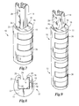
FIG. 7 shows a perspective view of the protector of FIG. 1, as engaged with an upright;
FIG. 8 shows a top view of FIG. 7;
FIG. 9 shows a plurality of protectors of FIG. 1, stacked on top of each other and each engaged with an upright;
FIG. 10 shows a perspective view of the protector of FIG. 1, exposing a shim embedded within the protector;
FIG. 11 shows a perspective view of the shim of FIG. 10;
FIG. 12 shows a side view of the shim of FIG. 10;
FIG. 13 shows a front view of the shim of FIG. 10;
FIG. 14 shows a cross sectional view of the protector of FIG. 1, disclosing the energy of the impact force being transferred within the protector;
FIG. 15 shows the stresses on the upright after the protector has received an impact force;
FIG. 16 shows a cross sectional view of another embodiment of the protector;
FIG. 17 shows a cross sectional view of another embodiment of the protector;
FIG. 18 shows a cross sectional view of another embodiment of the protector;
FIG. 19 shows a cross sectional view of another embodiment of the protector;
FIG. 20 shows a cross sectional view of another embodiment of the protector;
FIG. 21 shows a cross sectional view of the protector of FIG. 1, comprising a plurality of shims;
FIG. 22 shows a cross sectional view of the protector of FIG. 1, comprising another embodiment of the shim;
FIG. 23 shows a cross sectional view of the protector of FIG. 1, comprising another embodiment of the shim;
FIG. 24 shows a cross sectional view of another embodiment of the protector, comprising an internal core;
FIG. 25 shows a cross sectional view of another embodiment of the protector of FIG. 24, comprising another embodiment of the internal core;
FIG. 26 shows a cross sectional view of another embodiment of the protector of FIG. 24, comprising another embodiment of the internal core;
FIG. 27 shows a cross sectional view of another embodiment of the protector of FIG. 24, comprising a plurality of internal cores;
FIG. 28 shows a cross sectional view of the protector of FIG. 24, comprising damping material in the internal core;
FIG. 29 shows a perspective view of the protector of FIG. 1, comprising a smooth outer surface;
FIG. 30 shows a perspective view of the protector of FIG. 1, comprising another embodiment of the contours on the outer surface;
FIG. 31 shows a perspective view of the protector of FIG. 1, incorporating a high-visibility plate;
FIG. 32 shows a perspective view of the high-visibility plate of FIG. 31;
FIG. 33 shows a rear-perspective view of another embodiment of the protector;
FIG. 34 shows a rear-perspective view of the protector of FIG. 33, exposing the back wall of the protector;
FIG. 35 shows a cross sectional view of the protector of FIG. 33;
FIG. 36 shows a cross sectional view of the protector of FIG. 33, comprising another embodiment of the shim;
FIG. 37 shows a cross sectional view of another embodiment of the protector;
FIG. 38 shows a cross sectional view of another embodiment of the protector;
FIG. 39 shows a cross sectional view of another embodiment of the protector;
FIG. 40 shows a cross sectional view of another embodiment of the protector;
FIG. 41 shows a cross sectional view of the protector of FIG. 33, comprising a plurality of shims;
FIG. 42 shows a top view of another embodiment of the protector;
FIG. 43 shows a cross sectional view of the protector of FIG. 42;
FIG. 44 shows a rear-perspective view of the protector of FIG. 42, exposing the back wall of the protector;
FIG. 45 shows a cross sectional view of another embodiment of the protector;
FIG. 46 shows a rear-perspective view of the protector of FIG. 45, exposing the back wall of the protector;
FIG. 47 shows a cross sectional view of another embodiment of the protector;
FIG. 48 shows a top view of another embodiment of the protector, which engages with a non-traditional upright; and
FIG. 49 shows a top view of another embodiment of the protector, which engages with a different embodiment of the non-traditional upright.
DETAILED DESCRIPTION
Referring to the drawings, some of the reference numerals are used to designate the same or corresponding parts through several of the embodiments and figures shown and described. Corresponding parts are denoted in different embodiments with the addition of lowercase letters. Variations of corresponding parts in form or function that are depicted in the figures are described. It will be understood that variations in the embodiments can generally be interchanged without deviating from the invention.
FIGS. 1 through 6 depict a protector 10 for engaging and protecting a segment of the upright from an impact force by an external object. The protector 10 is used for absorbing energy and dissipating additional energy through damping to significantly reduce the resulting impact force while the force travels through the protector 10. After initial impact, the protector will absorb the energy and the damping effects will dissipate the energy from the impact force such that at least partially, if not all of, this energy diminishes before reaching the upright.
The protector 10 has a protector body 11 that allows engagement and positioning of the protector 10 on the segment of the upright. The protector body 11 is at least partially constructed from some type of energy absorbing and damping material, which is substantially and resiliently deformable upon receiving an impact from an external object (not shown). In this embodiment, elastomeric material is used to construct the protector body 11 because elastomeric material has an elastic component for absorbing shock (or isolating vibration), which in effect causes substantial and resilient deformation of the protector body 11 and allows the protector 10 to store and release potential energy. Elastomeric material also has a hysteretic damping component for dissipating energy.
The protector body 11 is also typically fabricated through an injection molding process. However, it will be understood that the protector body 11 does not necessarily need to be constructed from elastomeric material, so long as the protector body 11 has a sufficient energy absorbing component and damping component. It will also be understood that the protector body 11 can be fabricated using several anticipated manufacturing methods, such as an extrusion process or molding process.
The protector 10 is designed to protect a segment of the upright 14 from both frontal and side impact forces from an external object (not shown). As shown in FIGS. 7 and 8, the upright 14 is vertical. However, it will be understood that the protector 10 may protect uprights that are positioned to be substantially horizontal, diagonal, or otherwise oriented.
Referring back to FIGS. 1 through 6, the protector body 11 has an outer surface 16 and an inner surface 18 with a continuous volume of elastomeric material between both surfaces and a shim 28 embedded within it, discussed in detail below. The outer surface 16 is intended to be positionable to receive the impact force from the external object, when positioned on the upright 14. The inner surface 18 is intended to be positionable to abut the upright 14, when the protector 10 is in engagement with a segment of the upright 14. The inner surface 18 has a substantially square-shaped cross section, with a back wall 20 and two identical side walls 22. At the intersection of the back wall 20 and each side wall 22 is a corner 12. The design of the inner surface 18 accommodates traditional uprights comprising substantially square-shaped cross sections having sides 29 that are approximately two to three inches lengthwise. However, it should be understood that the inner surface 18 can be made to mount on non-traditional uprights 14 comprising cross sections of varying shape. Each side wall 22 comprises a shallow channel 25 running the length of the protector 10. These channels 25 facilitate the protector 10 being engaged with uprights 14 having flanges, or the like, running lengthwise along the upright 14.
At a position near the entrance to the opening 24, each side wall 22 also comprises a peripherally spanning tab 26, directed toward the center at the opening 24, joined to it during construction and through the molding process. As better understood with reference to FIG. 8, the tabs 26 are used to engage the back side of the upright 14 and secure engagement of the protector 10 with the upright 14. Each tab 26 is semi-flexible, enabling the protector 10 to quickly engage and disengage with the upright 14. As shown in FIG. 9, it is possible for multiple protectors 10 to engage and disengage with the upright 14 by stacking on top of each other, so long as the upright 14 has enough length.
As shown in FIGS. 11 through 13, a three-sided shim 28 is embedded within the protector 10 by being over molded into the protector 10 during construction. The shim 14 has a stiffness that is different than the stiffness of the protector body 11, so the shim 14 can provide structural support for the protector body 11. In this embodiment, the shim 28 is made of a rigid material that is substantially stiffer than the elastomeric material constructing the protector 10. Typically the shim 28 is made of a metal or hard plastic, however, it will be understood that any rigid material substantially stiffer than the elastomeric material constructing the protector 10 can also be used.
The shim 28 is embedded within the protector 10 at a position that is directly between the outer surface 16 and inner surface 18 except for the encapsulating segments of the protector body 11 both above and below the shim 28. The elastomer material molds through the shim 28 via a series of holes 30 located on all three sides, permanently securing the shim 28 in position within the protector 10. As shown, the series of holes 30 run along each of the sides of the shim 28; however, it will be understood that the pattern and number of holes 30 may vary from what is disclosed. In this embodiment, the series of holes 30 has a dual row pattern, which comprises two parallel series having three holes on the front of the shim 28 and one series having two holes on each of the sides of the shim 28. However, other hole 30 patterns, sizes, shapes, and numbers may work equally as well when implemented to securely embed the shim 28 within the protector 10 during construction. It will also be understood that the shim 28 may be bonded to the elastomer material with chemical adhesive or be left unbonded within the protector 10, so long as the shim 28 is secure when embedded within the protector 10.
As can be seen in FIG. 14, after an impact has occurred, the shim 28 will also partially deflect as well as transfer any remaining energy from the impact force 27 to each corner 12 of the opening 24. Remaining non-deflected energy from the impact force 27 will also be further absorbed through damping caused by the interaction between the shim 28 and the elastomeric material constructing the protector 10, especially at the portions of the shim 28 parallel to the side walls 22. In this embodiment, the shim 28 is considered to be at least partially and approximately equidistant from the inner surface 18, causing it to have a c-channel shape that has a substantially square-shaped cross section and similar to the substantially square-shape of the inner surface 18. Being approximately equidistant from the inner surface 18 ensures protection on the sides of the upright 14 from receiving an impact. It should be understood that certain portions of the shim 28 q will still be considered approximately equidistant even if those portions do not completely follow the substantially-square shape of the inner surface 18 q.
As shown in FIG. 15, upon transferring the impact force to each corner 12, minimal amounts of energy from this impact force will pass beyond the shim 28, go through to the inner surface 18, and cause stress to the upright 14. As the energy from the impact force enters the upright 14, through an entrance area 15 on the upright 14, the impact force spreads out and to the back edges of the upright 14. Ultimately, the energy spreads into a peak-buildup location 19, where the most stress on the upright 14 occurs, and dissipates. Overall, since most energy of the impact force is absorbed while being transferred throughout the protector 10, the stress on the upright 14 is minimal when entering the upright 14 at the entrance location 15. Therefore, only a minor amount of energy enters and spreads throughout the upright 14, typically only causing the upright 14 to minimally bend and flex after an impact. It should be understood that the peak-buildup location 19 could be elsewhere when other embodiments of the protector 10 have engaged with the upright 14.
Referring back to FIGS. 4 through 6, a column spacer 32 is molded into the unitary structure of the protector 10 at both ends, substantially creating the back wall 20 of the inner surface 18. In this embodiment, the column spacer 32 is positioned between the shim 28 and the inner surface 18, but does not actually pass beyond the shim 28. In this embodiment, the column spacer 32 comprises a waffle-shaped pattern, causing the back wall 20 to have less points of contact with the upright 14 than the side walls 22, when the protector is in engagement with the upright 14. Essentially, when an impact force is received by the protector 10, the waffle-shaped pattern enables the back wall 20 to partially buckle and deform before the energy of the impact force travels into the upright 14. Partial buckling occurs when the waffle-shaped pattern of the column spacer 32 bends and gives way upon the outer surface 16 receiving the impact force. In effect, the column spacer 32 helps to further absorb energy from the impact force before the energy enters the upright 14. The waffle-shaped pattern also reduces the stiffness of the back wall 20 of the inner surface 18. There are also a series of miniature interconnectors 35 crossing the gaps at various locations; these interconnectors ensure the column spacer 32 returns to its appropriate shape after the protector 10 receives an impact.
The column spacer 32 remains detached from the shim 28, further facilitating both friction and hysteretic damping between the shim 28, the column spacer 32, and the column spacer 32. Friction damping occurs when portions of the shim 28 rub against the protector body 12. Any residual energy from the impact force passing beyond the shim 28 should sufficiently be absorbed from such damping effects, further ensuring the energy from the impact force will not create damage to the upright 14. It will be understood that in certain circumstances adhesives or other joining mechanisms may be used to join the column spacer 32 to the shim 28, when desired.
The protector 10 has a plurality of series of shallow contours 34 spanning the outer surface 16 of the protector 10. These contours 34 facilitate the substantial and resilient deformation of the protector 10 by disturbing the smooth outer surface 16, making it less likely the protector 10 will directly receive an impact at once. The design of these contours 34 is convenient to place a portion of reflective tape, or the like, within each, so the protector 10 becomes more visible to onlookers and makes intentional avoidance of the upright 14 easier.
As shown in FIG. 16, another embodiment of the protector 10 a incorporates a shim 28 a having a greater thickness than the shim of the embodiment discussed above. The shim 28 a is made of rigid material that has a substantially greater stiffness than the stiffness of the elastomeric material constructing the protector body 11 a, so as to greatly increase the structural support for the protector body 11 a. Here, the shim 28 a causes the protector body 11 a to be far stiffer than the protector disclosed in other embodiments. Typically the shim 28 a is made of a metal material or hard plastic material; however, it will be understood that any rigid material having a substantially greater stiffness than the stiffness of the elastomeric material constructing the protector body 11 a can be used.
As shown in FIG. 17, another embodiment of the protector 10 b incorporates a series of mounting devices 36 b, located on both side walls 22 b of the inner surface 18 b. These mounting devices 36 b ensure the protector 10 b remains stationary when the protector 10 b is in engagement with the upright 14 b. The mounting devices 36 b interlock with holes, or the like, located along the upright 14 b.
As shown in FIG. 18, another embodiment of the protector 10 c is adapted to incorporate a joining mechanism 38 c that runs through the periphery of both the protector 10 c and the upright 14 c. The joining mechanism 38 c permanently mounts the protector 10 c to the upright 14 c through holes, or the like, aligned on both sides of the upright 14 c. The joining mechanism 38 c also allows the protector 10 c to engage with the upright 14 c at some distance above the surface in which the upright 14 c is erected. Engaging the protector 10 c with the upright some distance above the surface makes it easier for the protector 10 c to protect the upright 14 c at locations that are more vulnerable to specific types of impacts from the surrounding environment. Furthermore, the joining mechanism 38 c is displayed as a nut and bolt combination; however, it is understood that the joining mechanism 38 c can be any mechanism able to permanently mount the protector 10 c to the upright 14 c.
As shown in FIG. 19, another embodiment of the protector 10 d incorporates a shim 28 d embedded within the protector body 11 d at a position considerably closer to the inner surface 18 d than the outer surface 16 d. Embedding the shim 28 d closer to the inner surface 18 d allows the shim 28 d to receive and deflect energy from an impact force when it is closer to the inner surface 18 d than the outer surface 16 d.
As shown in FIG. 20, another embodiment of the protector 10 e incorporates a shim 28 e embedded within the protector body 11 e at a position considerably closer to the outer surface 16 g than the inner surface 18 e. Embedding the shim 28 e closer to the outer surface 16 e allows the shim 28 e to receive and deflect energy from an impact force when it is closer to the outer surface 16 e than the inner surface 18 e.
As shown in FIG. 21, another embodiment of the protector 10 f incorporates both a shim 28 f and a second shim 40 f embedded within the protector body 11 f. The shim 28 f is positioned closer to the inner surface 18 f, and the second shim 40 f is positioned closer to the outer surface 16 f. Embedding both the shim 28 f and second shim 40 f within the protector body 11 f causes energy from an impact force to be deflected more than once before that energy has an opportunity to travel through to the inner surface 18 f. A plurality of deflections make it more probable that minimal energy from an impact force received on the outer surface 16 f will travel through to the inner surface 18 f and into the upright 14 f.
As shown in FIG. 22, another embodiment of the protector 10 g incorporates a shim 28 g comprising an upset 44 g positioned on both of its sides. Each upset 44 g helps to secure the shim 28 g after being embedded in the protector body 11 g, by locking the shim 28 g in place. These upsets also alleviate any need for the addition of adhesives, joining mechanisms, or the like, and allowing the shim 28 g to remain completely secured while still being detached from the column spacer 32 g.
As shown in FIG. 23, another embodiment of the protector 10 h incorporates a three-sided shim 28 h having a portion of two sides of the shim 28 h forming part of the inner surface 18 h causing a portion of the shim 28 h to abut the upright 14 h when the protector 10 h is in engagement with the upright 14 h. Embodying the shim 28 h in this manner keeps it from walking after the protector 10 h has received an impact from an external object. This embodiment of the shim 28 h also ensures the shim 28 h will resist bending after the protector 10 h has received an impact from an external object. The shim will also provide an additional amount of rigidity to the elastomeric material which will result in better retention and fit to the column.
As shown in FIG. 24, another embodiment of the protector 10 i has an internal core 42 i centrally located within the protector body 11 i. The internal core 42 i creates a spring-like damping effect within the protector body 11 i after receiving an impact. Upon receiving an impact, the protector body 11 i will compress around the internal core 42 i and decompress immediately thereafter, which further facilitates absorption of the energy from the impact force. The shim 28 i is embedded within the protector body 11 i at a position directly between the outer surface 16 i and the internal core 42 i. As shown in FIG. 25, another embodiment of the protector 10 j has a centrally located internal core 42 j that has a cross section with a rectangular shape. As shown in FIG. 26, another embodiment of the protector 10 k has a centrally located internal core 42 k that has a five-sided pentagonal shape. As shown in FIG. 27, another embodiment of the protector 10 l has a plurality of centrally located internal cores 42 l. In this embodiment, each of the internal cores 42 l creates their own spring-like damping effect within the protector body 11 l. As shown in FIG. 28, another embodiment of the protector 10 m has a centrally located internal core 42 m filled with damping material 46 m. The internal core 42 m creates a spring-like damping effect within the protector body 11 m that further facilitates absorption of the energy from an impact. Upon receiving an impact, the protector body 11 m will compress around the internal core 42 m, the damping material 46 m will then absorb portions of the energy from the impact force just before the internal core 42 m decompresses immediately thereafter.
As shown in FIG. 29, another embodiment of the protector 10 n has an outer surface 16 n that is smooth and with no impressed contours. As shown in FIG. 30, the protector 10 o has an outer surface 16 o comprising a plurality of individual series of shallow contours 34 o impressed to the outer surface 16 o. These contours 34 o help facilitate energy absorption within the protector 10 o by breaking up surface smoothness of the outer surface 16 o such that the protector 10 o does not receive an entire impact at once.
As shown in FIGS. 31 and 32, another embodiment of the protector 10 p incorporates a high-visibility plate 48 p releasably joined to its outer surface 16 p. The high-visibility plate 48 p is brightly colored and makes the protector 10 p more visible to onlookers, making avoidance of the upright is easier when the high-visibility plate 48 p releasably joined to the outer surface 16 p. Since the high-visibility plate 48 p can be made from polymer plastic material, it can also provide additional stiffness and support for the protector body 11 p, if needed. The high-visibility plate 48 p replaces reflective tape that could be better suited for other embodiments of the protector 10 p.
As shown in FIGS. 33 and 34, another embodiment of the protector 10 q incorporates an embodiment of the column spacer 32 q molded into the unitary structure of body 12 q at both the ends, substantially creating the back wall 20 q of the inner surface 18 q. Gaps in the structure of protector body 11 q create the column spacer 32 q by running lengthwise on both of its sides. The column spacer 32 q is positioned between the shim 28 q and the inner surface 18 q, but does not actually pass beyond the shim 28 q. There are also a series of miniature interconnectors 35 q crossing the gaps at various locations; these interconnectors ensure the column spacer 32 q returns to its appropriate shape after protector 10 q receives an impact.
The column spacer 32 q reduces the stiffness of the protector 10 q centrally around the upright 14 q, allowing for more deformation adjacent to the upright 14 q. The column spacer 32 q remains detached from the shim 28 q, further facilitating both friction and hysteretic damping between the shim 28 q, the column spacer 32 q, and the column spacer 32 q. Friction damping occurs when portions of the shim 28 q rub against the protector body 12 q. Any residual energy from the impact force passing beyond the shim 28 q should sufficiently be absorbed from such damping effects, further ensuring the energy from the impact force will not create damage to the upright 14 q. It will be understood that in certain circumstances adhesives or other joining mechanisms may be used to join the column spacer 32 q to the shim 28 q, when desired.
As shown in FIG. 35, the shim 28 q of this embodiment is considered to be at least partially and approximately equidistant from the outer surface 18 q, causing it to have a cross section that is substantially rounded and similar to the rounded shape of the outer surface 18 q. Being approximately equidistant from the outer surface 18 q ensures protection on the sides of the upright 14 q from receiving an impact force. It should be understood that certain portions of the shim 28 q will still be considered approximately equidistant even if those portions do not completely follow the shape of the outer surface 18 q.
As shown in FIG. 36, another embodiment of the protector 10 r incorporates a shim 28 r comprising a cross section that is approximately equidistant from the outer surface 16 r and having a greater thickness than the shim of the embodiment disclosed in FIGS. 33 through 35, discussed above. The shim 28 r is made of rigid material that has a substantially greater stiffness than the stiffness of the elastomeric material constructing the protector body 11 r, so as to greatly increase the structural support for the protector body 11 r. Here, the shim 28 r causes the protector body 11 r to be far stiffer than the protector disclosed in other embodiments. Typically the shim 28 r is made of a metal material or hard plastic material; however, it will be understood that any rigid material that having a substantially greater stiffness than the stiffness of the elastomeric material constructing the protector body 11 r can be appropriately implemented.
The column spacer 32 r is molded into the unitary structure of body 12 r at both the ends, substantially creating the back wall 20 r of the inner surface 18 r. Gaps in the structure of protector body 11 r create the column spacer 32 r by running lengthwise on both of its sides. The column spacer 32 r is positioned between the shim 28 r and the inner surface 18 r, but does not actually pass through the shim 28 r.
As shown in FIG. 37, another embodiment of the protector 10 s incorporates a series of mounting devices 36 s, located on both side walls 22 s of the inner surface 18 s. These mounting devices 36 s ensure the protector 10 s remains stationary while in engagement with the upright 14 s. The mounting devices 36 s interlock with holes, or the like, located along the upright 14 s. This embodiment of the protector 10 s also incorporates a shim 28 s that is approximately equidistant from the outer surface 16 s and a column spacer 32 s created by running lengthwise on both of its sides, discussed above.
As shown in FIG. 38, another embodiment of the protector 10 t is adapted to incorporate a joining mechanism 38 t that runs through the periphery of both the protector 10 t and the upright 14 t. The joining mechanism 38 t permanently mounts the protector 10 t to the upright 14 t through a hole, or the like, on both sides of the upright 14 t, further discussed in a previous embodiment above. This embodiment of the protector 10 t also incorporates a shim 28 t that is approximately equidistant from the outer surface 16 t and a column spacer 32 t created by running lengthwise on both of its sides, discussed above.
As shown in FIG. 39, another embodiment of the protector 10 u incorporates a shim 28 u embedded within the protector body 11 u at a position considerably closer to the inner surface 18 u than the outer surface 16 u. Embedding the shim 28 u closer to the inner surface 18 u allows the shim 28 u to receive and deflect energy from an impact force when it is closer to the inner surface 18 u than the outer surface 16 u. This embodiment of the protector 10 u incorporates a shim 28 u having a cross section approximately equidistant from the outer surface 16 u and a column spacer 32 u that is created by gaps running lengthwise down both of its sides, discussed above.
As shown in FIG. 40, another embodiment of the protector 10 v incorporates a shim 28 v embedded within the protector body 11 v at a position considerably closer to the outer surface 16 v than the inner surface 18 v. Embedding the shim 28 v closer to the outer surface 16 v allows the shim 28 v to receive and deflect energy from an impact force when it is closer to the outer surface 16 v than the inner surface 18 v. This embodiment of the protector 10 v also incorporates a shim 28 v having a cross section approximately equidistant from the outer surface 16 v and a column spacer 32 v that is created by gaps running lengthwise down both of its sides, discussed above.
As shown in FIG. 41, another embodiment of the protector 10 w incorporates both a shim 28 w and a second shim 40 w embedded within the protector body 11 w. The shim 28 w is positioned closer to the inner surface 18 w, and the second shim 40 w is positioned closer to the outer surface 16 w. Embedding both the shim 28 w and second shim 40 w within the protector body 11 w causes energy from an impact force to be deflected more than once before that energy has an opportunity to travel through to the inner surface 18 w. A plurality of deflections make it more likely that minimal energy from an impact force received on the outer surface 16 w will travel through to the inner surface 18 w and into the upright 14 w. In this embodiment of the protector 10 w, the shim 28 w and second shim 40 w both have a cross section approximately equidistant from the outer surface 16 w and the column spacer 32 w is created by gaps running lengthwise down both of its sides, discussed above.
As shown in FIGS. 42 through 44, the protector 10 x does not comprise tabs at the entrance to the opening 24 x, created by the inner surface 18 x on the protector body 11 x. Without tabs, the protector 10 x can quickly and easily be in engagement and disengagement with the upright, making the protector 10 x useful for temporary purposes. The protector body 11 x in this embodiment also does not comprise a column spacer, making the protector 10 x less equipped to absorb energy from an impact centrally around an upright, which can be advantageous for some applications.
A shim 28 x is embedded within the protector body 11 x at a position between the outer surface 16 x and inner surface 18 x. In this embodiment, the shim 28 x has a cross section that is rounded into a shape for deflecting frontal impacts received by the outer surface 16 x. After a frontal impact has occurred, the shim 28 x will partially deflect as well as transfer any remaining energy from the impact force (not shown). Remaining non-deflected energy from the impact force will also further be absorbed through damping caused by the interaction between the shim 28 x and the elastomeric material constructing the protector body 11 x.
As shown in FIGS. 45 and 46, the protector 10 y has a protector body 11 y comprising a plurality of centrally positioned column spacers 32 y molded to the top and bottom of the protector body fly, forming the back wall 20 y of the inner surface 18 y. In this embodiment, four column spacers 32 y are shown, but it should be understood that more or less column spacers 32 y could be incorporated into the protector body 11 y. The position of each of these column spacers 32 y is between the shim 28 y and the inner surface 18 y, none of which pass beyond the shim 28 y. Gaps in the structure of the protector 12 y create each of these column spacers 32 y by running lengthwise between each of the column spacers 32 y.
Essentially, when an impact force is received by the protector 10 y, the column spacers 32 y partially buckle and deform before the energy of the impact force travels into the upright 14 y. Partial buckling occurs when the column spacers 32 y bend and give way upon the outer surface 16 y receiving the impact force. In effect, the column spacers 32 y help to further absorb energy from the impact force before the impact energy encounters the upright 14 y.
These column spacers 32 y remain detached from the shim 28 y, further facilitating both friction and hysteretic damping between the shim 28 y and the column spacers 32 y. Any residual impact energy from the impact force passing beyond the shim 28 y should sufficiently be absorbed from such damping effects, further ensuring the energy from the impact force will not create damage to the upright 14 y. It will be understood that in certain circumstances adhesives or other joining mechanisms may be used to join the column spacers 32 y to the shim 28 y, when desired.
As shown in FIG. 47, the protector 10 z does not comprise tabs at the entrance to the opening 24 z, created by the inner surface 18 z on the protector body 11 z. Without tabs, the protector 10 z can quickly and easily be in engagement and disengagement with the upright, making the protector 10 z useful for temporary purposes. The protector 10 z also comprises a plurality of centrally positioned column spacers 32 z molded in conjunction with each other on the top and bottom of the protector body 11 y, as discussed in the previous embodiment above.
As shown in FIG. 48, another embodiment of the protector 10 aa comprises an inner surface 18 aa with a circular cross section. The inner surface 18 aa creates an opening 24 aa that facilitates engaging the protector 10 aa to a non-traditional upright 14 aa that comprises a circular cross section. As shown in FIG. 49, another embodiment of the protector 10 bb has an inner surface 18 bb with an octagonal cross section. The inner surface 18 bb creates an opening 24 bb that facilitates engaging the protector 10 bb to a non-traditional upright 14 bb that comprises an octagonal cross section. It will be understood that the inner surface of an embodiment of the protector may have shapes allowing this surface to facilitate abutting that embodiment of the protector against various non-traditional uprights that comprises cross sections of various widths and shapes.
This invention has been described with reference to several preferred embodiments. Many modifications and alterations will occur to others upon reading and understanding the preceding specification. It is intended that the invention be construed as including all such alterations and modifications in so far as they come within the scope of the appended claims or the equivalents of these claims.

Claims (88)

The invention claimed is:
1. A protector for engaging and protecting a segment of an upright from an impact force by an external object and for absorbing and damping the resulting impact force traveling through said protector, said protector comprising:
a protector body, said protector body being at least partially constructed of an energy absorbing and damping material, said protector body comprising an outer surface and an inner surface, said protector body allowing engagement and positioning of said protector on at least a segment of the upright;
said outer surface of said protector body being positionable to receive the impact force from the external object when positioned on the upright;
said inner surface of said protector body being positionable to abut the upright when said protector is in engagement with the upright;
a shim, said shim being at least partially embedded in said protector body, said shim having a stiffness that is different than the stiffness of said protector body, said shim providing increased structural support for said protector body; and
at least one column spacer molded into said inner surface of said protector body, each said at least one column spacer partially buckling when said outer surface of said protector body has received the impact force from the external object, and each said at least one column spacer does not pass beyond said shim to said outer surface of said protector body.
2. The protector of claim 1 in which each said at least one column spacer comprises a waffle-shaped pattern.
3. The protector of claim 1 wherein said at least one column spacer comprises a plurality of column spacers molded into the inner surface of said protector body, said plurality of column spacers partially buckling when said outer surface of said protector body has received the impact force from the external object.
4. The protector of claim 1 further comprising a plurality of tabs joined to said protector body, said plurality of tabs assists said protector in engagement with the upright.
5. The protector of claim 1 further comprising a second shim partially embedded in said protector body.
6. The protector of claim 1 further comprising a high-visibility plate releasably joinable to said outer surface of said protector body.
7. The protector of claim 1 further comprising a joining mechanism for permanently mounting the protector to the upright.
8. The protector of claim 1 wherein the stiffness of said shim is greater than the stiffness of said protector body.
9. The protector of claim 1 wherein said energy absorbing and damping material is at least partially elastomeric material.
10. The protector of claim 1 wherein said protector body has a continuous volume of energy absorbing and damping material between said inner surface and said outer surface.
11. The protector of claim 1 wherein said outer surface of said protector body comprising a plurality of contours.
12. The protector of claim 1 wherein said shim is constructed of rigid material.
13. The protector of claim 1 wherein said shim is constructed of either metallic material or plastic material.
14. The protector of claim 1 wherein said shim is approximately equidistant from said outer surface of said protector body.
15. The protector of claim 1 wherein said shim is approximately equidistant from said inner surface of said protector body.
16. The protector of claim 1 wherein said shim comprising an upset at least partially securing said shim in said protector body.
17. The protector of claim 1 in which said shim has a series of holes in a dual row pattern.
18. The protector of claim 1 wherein said protector body comprising an internal core.
19. The protector of claim 1 wherein:
said protector body comprising an internal core; and
said internal core is filled with damping material.
20. The protector of claim 1 wherein the damping of the impact force in said protector body is caused by friction between said shim and said protector body.
21. The protector of claim 1 wherein the damping of the impact force in said protector body is caused through hysteresis.
22. The protector of claim 1 wherein said shim partially deflecting the impact force from reaching said inner surface of said protector body.
23. The protector of claim 1 wherein said protector is partially fabricated through an injection molding process or extrusion process.
24. The protector of claim 1 wherein said inner surface of said protector body comprising a series of mounting devices assisting said protector in engaging with the upright.
25. The protector of claim 1 wherein said inner surface of said protector body creates an opening that has a cross-section that is substantially one of square, circular, or octagonal.
26. A protector for engaging and protecting a segment of an upright from an impact force by an external object and for absorbing and damping the resulting impact force traveling through said protector, said protector comprising:
a protector body, said protector body being at least partially constructed of an energy absorbing and damping material, said protector body comprising an outer surface and an inner surface, said protector body allowing engagement and positioning of said protector on at least a segment of the upright;
said outer surface of said protector body being positionable to receive the impact force from the external object when positioned on the upright;
said inner surface of said protector body being positionable to abut the upright when said protector is in engagement with the upright;
a shim, said shim being at least partially embedded in said protector body, said shim having a stiffness that is different than the stiffness of said protector body, said shim providing increased structural support for said protector body; and
a column spacer molded into said inner surface of said protector body, said column spacer does not pass beyond said shim to said outer surface of said protector body, and said column spacer partially buckling when said outer surface has received the impact force.
27. The protector of claim 26 further comprising a plurality of tabs joined to said protector body, said plurality of tabs assists said protector in engagement with the upright.
28. The protector of claim 26 further comprising a second shim partially embedded in said protector body.
29. The protector of claim 26 further comprising a high-visibility plate releasably joinable to said outer surface of said protector body.
30. The protector of claim 26 further comprising a joining mechanism for permanently mounting the protector to the upright.
31. The protector of claim 26 wherein the stiffness of said shim is greater than the stiffness of said protector body.
32. The protector of claim 26 in which said column spacer comprises a waffle-shaped pattern.
33. The protector of claim 26 wherein said outer surface of said protector body comprising a plurality of contours.
34. The protector of claim 26 wherein said energy absorbing and damping material is at least partially elastomeric material.
35. The protector of claim 26 wherein said protector body has a continuous volume of energy absorbing and damping material between said inner surface and said outer surface.
36. The protector of claim 26 wherein said shim is constructed of rigid material.
37. The protector of claim 26 wherein said shim is constructed of either metallic material or plastic material.
38. The protector of claim 26 wherein said shim is approximately equidistant from said outer surface of said protector body.
39. The protector of claim 26 wherein said shim is approximately equidistant from said inner surface of said protector body.
40. The protector of claim 26 wherein said shim comprising an upset at least partially securing said shim in said protector.
41. The protector of claim 26 in which said shim has a series of holes in a dual row pattern.
42. The protector of claim 26 wherein said protector body comprising an internal core.
43. The protector of claim 26 wherein:
said protector comprising an internal core; and
said internal core is filled with damping material.
44. The protector of claim 26 wherein the damping of the impact force in said protector body is caused by friction between said shim and said protector body.
45. The protector of claim 26 wherein the damping of the impact force in said protector is caused through hysteresis.
46. The protector of claim 26 wherein said shim partially deflecting the impact force from reaching said inner surface of said protector body.
47. The protector of claim 26 wherein said protector is partially fabricated through an injection molding process or extrusion process.
48. The protector of claim 26 wherein said inner surface of said protector body comprising a series of mounting devices assisting said protector in engaging with the upright.
49. The protector of claim 26 said inner surface of said protector body creates an opening that has a cross-section that is substantially one of square, circular, or octagonal.
50. A protector for engaging and protecting a segment of an upright from an impact force by an external object and for absorbing and damping the resulting impact force traveling through said protector, said protector comprising:
a protector body, said protector body being at least partially constructed of an energy absorbing and damping material that substantially and resiliently deforms when receiving the impact force from the external object, said protector body comprising an outer surface and an inner surface, said protector body allowing engagement and positioning of said protector on at least a segment of the upright;
said outer surface of said protector body being positionable to receive the impact force from the external object when positioned on the upright;
said inner surface of said protector body being positionable to abut the upright when said protector is in engagement with the upright;
a shim, said shim being at least partially embedded in said protector body, said shim being made of a rigid material and having a stiffness that is different than the stiffness of said protector body, said shim providing increased structural support for said protector body; said shim at least partially deflecting the impact force while traveling through said protector body; and
at least one column spacer molded into said inner surface of said protector body, each said at least one column spacer does not pass beyond said shim to said outer surface of said protector body.
51. The protector of claim 50 in which each said at least one column spacer comprises a waffle-shaped pattern.
52. The protector of claim 50 wherein said at least one column spacer comprises a plurality of column spacers molded into the inner surface of said protector body, said plurality of column spacers partially buckling when said outer surface of said protector body has received the impact force.
53. The protector of claim 50 further comprising a plurality of tabs joined to said protector body, said plurality of tabs assists said protector in engagement with the upright.
54. The protector of claim 50 further comprising a second shim partially embedded in said protector body.
55. The protector of claim 50 further comprising a high-visibility plate releasably joinable to said outer surface of said protector body.
56. The protector of claim 50 further comprising a joining mechanism for permanently mounting said protector to the upright.
57. The protector of claim 50 wherein the stiffness of said shim is greater than the stiffness of said protector body.
58. The protector of claim 50 wherein said outer surface of said protector body comprising a plurality of contours.
59. The protector of claim 50 wherein said energy absorbing and damping material is at least partially elastomeric material.
60. The protector of claim 50 wherein said protector body has a continuous volume of energy absorbing and damping material between said inner surface and said outer surface.
61. The protector of claim 50 wherein said shim is constructed of either metallic material or plastic material.
62. The protector of claim 50 wherein said shim is approximately equidistant from said outer surface of said protector body.
63. The protector of claim 50 wherein said shim is approximately equidistant from said inner surface of said protector body.
64. The protector of claim 50 wherein said shim comprising an upset at least partially securing said shim in said protector body.
65. The protector of claim 50 in which said shim has a series of holes in a dual row pattern.
66. The protector of claim 50 wherein said protector comprising an internal core.
67. The protector of claim 50 wherein:
said protector comprising an internal core; and
said internal core is filled with damping material.
68. The protector of claim 50 wherein the damping of the impact force in said protector body is caused by friction between said shim and said protector body.
69. The protector of claim 50 wherein said damping of the impact force in said protector body is caused through hysteresis.
70. The protector of claim 50 wherein said shim partially deflecting the impact force from reaching said inner surface of said protector body.
71. The protector of claim 50 wherein said protector is partially fabricated through an injection molding process or extrusion process.
72. The protector of claim 50 wherein said inner surface of said protector body comprising a series of mounting devices assisting said protector in engaging with the upright.
73. The protector of claim 50 wherein said inner surface of said protector body creates an opening that has a cross-section that is substantially one of square, circular, or octagonal.
74. A protector for engaging and protecting a segment of an upright from an impact force by an external object and for absorbing and damping the resulting impact force traveling through said protector, said protector comprising:
a protector body, said protector body being at least partially constructed of an elastomeric material that substantially and resiliently deforms when receiving the impact force from the external object, said protector body comprising an outer surface and an inner surface, said protector body allowing engagement and positioning of said protector on at least a segment of the upright;
said outer surface of said protector body being positionable to receive the impact force from the external object when positioned on the upright;
said inner surface of said protector body being positionable to abut the upright when said protector is in engagement with the upright, said inner surface creating an opening with a substantially square-shaped cross section and plurality of corners;
a shim, said shim being at least partially embedded in said protector body, said shim being made of a rigid material and having a stiffness that is greater than the stiffness of said protector body, said shim providing increased structural support for said protector body, said shim is approximately equidistant from said opening of said inner surface of said protector body, said shim at least partially deflecting the impact force while traveling through said protector body and transferring the remaining impact force to each of said corners of said opening;
a column spacer molded into one side of said inner surface, said column spacer does not pass beyond said shim to said outer surface, said column spacer is detached from said shim, said column spacer comprising a waffle-shaped pattern, said column spacer partially buckling when said outer surface receives the impact force; and
a plurality of tabs joined to said protector body, said plurality of tabs assists said protector in engagement with the upright.
75. The protector of claim 74 further comprising a second shim partially embedded in said protector body.
76. The protector of claim 74 further comprising a high-visibility plate releasably joinable to said outer surface of said protector body.
77. The protector of claim 74 further comprising a joining mechanism for permanently mounting the protector to the upright.
78. The protector of claim 74 wherein said outer surface of said protector body comprising a plurality of contours.
79. The protector of claim 74 wherein said protector body has a continuous volume of elastomeric material between said inner surface and said outer surface.
80. The protector of claim 74 wherein said shim is constructed of either metallic material or plastic material.
81. The protector of claim 74 wherein said shim comprising an upset at least partially securing said shim embedded in said protector body.
82. The protector of claim 74 in which said shim has a series of holes in a dual row pattern.
83. The protector of claim 74 wherein said protector comprising an internal core.
84. The protector of claim 74 wherein:
said protector comprising an internal core; and
said internal core is filled with damping material.
85. The protector of claim 74 said protector is partially fabricated through an injection molding process or extrusion process.
86. The protector of claim 74 wherein said inner surface of said protector body comprising a series of mounting devices assisting said protector in engaging with the upright.
87. The protector of claim 74 wherein the damping of the impact force in said protector body is caused by friction between said shim and said protector body.
88. The protector of claim 74 wherein said damping of the impact force in said protector body is caused through hysteresis.
US14/157,121 2013-01-16 2014-01-16 Upright protector Active 2034-12-12 US9752291B2 (en)

Priority Applications (1)

Application Number Priority Date Filing Date Title
US14/157,121 US9752291B2 (en) 2013-01-16 2014-01-16 Upright protector

Applications Claiming Priority (2)

Application Number Priority Date Filing Date Title
US201361753114P 2013-01-16 2013-01-16
US14/157,121 US9752291B2 (en) 2013-01-16 2014-01-16 Upright protector

Publications (2)

Publication Number Publication Date
US20140196997A1 US20140196997A1 (en) 2014-07-17
US9752291B2 true US9752291B2 (en) 2017-09-05

Family

ID=51164332

Family Applications (1)

Application Number Title Priority Date Filing Date
US14/157,121 Active 2034-12-12 US9752291B2 (en) 2013-01-16 2014-01-16 Upright protector

Country Status (1)

Country Link
US (1) US9752291B2 (en)

Cited By (12)

* Cited by examiner, † Cited by third party
Publication number Priority date Publication date Assignee Title
US20180213935A1 (en) * 2015-07-22 2018-08-02 Innovation Central Pty Ltd Impact protection device clip
US10759641B1 (en) * 2017-01-12 2020-09-01 ReEnvision Products, LLC Protective lift pad for materials handling vehicle
USD911884S1 (en) * 2019-02-13 2021-03-02 Rodney Lee Loschiavo Marine fender
USD922917S1 (en) * 2019-02-13 2021-06-22 Rodney Lee Loschiavo Marine fender
US11046267B2 (en) 2018-03-23 2021-06-29 JPAV Corporation Secondary bumper assemblies for vehicles
US11070037B2 (en) * 2018-10-12 2021-07-20 International Business Machines Corporation Multi-directional impact protection with magnitude and direction indicator
USD931938S1 (en) 2018-12-31 2021-09-28 Retail Design Services, LLC Sign edge bumper
US11145226B2 (en) 2018-06-04 2021-10-12 Retail Design Services, LLC Sign edge bumper assembly
US11168509B2 (en) * 2018-04-11 2021-11-09 Ehmke Manufacturing Company, Inc. Doorframe protection device
US20220033182A1 (en) * 2020-07-31 2022-02-03 Mccue Corporation Pallet Shelf
USD950772S1 (en) * 2019-08-21 2022-05-03 Taco Metals, Llc Extruded vinyl rub rail
USD1022248S1 (en) * 2022-04-12 2024-04-09 Taco Metals Llc Extruded vinyl rub rail

Families Citing this family (7)

* Cited by examiner, † Cited by third party
Publication number Priority date Publication date Assignee Title
US9414677B2 (en) * 2013-01-16 2016-08-16 Southwest Agri-Plastics, Inc. Impact barrier for a storage rack
AU2014320099B2 (en) * 2013-09-16 2018-07-05 A-Fax Limited Structure protector
BE1021279B1 (en) * 2013-09-18 2015-10-13 Boplan Bvba RACK PROTECTION
WO2015139023A1 (en) * 2014-03-14 2015-09-17 Mccue Corporation Protective barrier
US20180116401A1 (en) * 2016-10-31 2018-05-03 Jin Ok Kim Rack post protection apparatus
FR3086960B1 (en) * 2018-10-08 2021-05-14 Soc De Distribution Dequipements Et Fournitures Industrielles PROTECTIVE ELEMENT FOR A SHELF UPRIGHT, ESPECIALLY PALLETIZER.
US20230151689A1 (en) * 2021-11-17 2023-05-18 Mccue Corporation Goalpost mounting assembly

Citations (65)

* Cited by examiner, † Cited by third party
Publication number Priority date Publication date Assignee Title
US179690A (en) * 1876-07-11 Improvement in piano-leg protectors
US1620933A (en) 1926-03-01 1927-03-15 Joseph T Wilcox Casing protector
US1679117A (en) 1927-02-26 1928-07-31 Clayton D Dye Furniture fender
US3303937A (en) 1964-09-09 1967-02-14 Interlake Steel Corp Pallet rack
US3372552A (en) 1967-02-23 1968-03-12 Orval E. Liddell Wooden fender pile protecting apparatus
US3472489A (en) 1968-06-05 1969-10-14 Henry Baylin Baluster jackets
US3559356A (en) 1968-04-19 1971-02-02 Specialties Const Resilient corner bead
US3626487A (en) 1970-03-03 1971-12-07 Edward A Seiz Fire and vermin resistant storage structure having fail-safe features
US3681885A (en) 1970-06-22 1972-08-08 Franklin Goggins Wall cover assemblies
US3712003A (en) 1970-06-01 1973-01-23 Specialties Const Wall and corner guard assembly
US3717968A (en) 1970-07-16 1973-02-27 Specialties Const Surface-mounted wall guards
US4012878A (en) 1976-04-14 1977-03-22 Astro Plastics, Inc. Unitary wall member guard
US4555870A (en) 1983-08-22 1985-12-03 Magna International, Inc. Door edge guard trim
US4585131A (en) 1983-12-19 1986-04-29 Amstore Corporation Variable decor merchandising system
US4703531A (en) * 1986-09-29 1987-11-03 B. J. Mountain, Inc. Padded rail cap
US4768320A (en) 1986-10-10 1988-09-06 Weller Rick W Door frame guard
US4898285A (en) 1988-12-02 1990-02-06 Field Frank P Merchandise rack covering system
US4946727A (en) 1989-03-08 1990-08-07 Gerald Kessler Dual durometer rub rail
US5096753A (en) 1990-02-12 1992-03-17 Mccue Corporation Protective strip assembly
US5186455A (en) * 1992-01-27 1993-02-16 Rosetta James A Protective collar for golf tees
US5203130A (en) 1991-11-26 1993-04-20 Freelove James W Door frame shield
US5369925A (en) 1993-06-01 1994-12-06 Hardy Manufacturing, Inc. Post protector
US5411234A (en) 1992-03-24 1995-05-02 Croon & Lucke Maschinenfabrik Gmbh Stand for the storage of two-dimensional workpieces
US5603140A (en) 1996-01-05 1997-02-18 Pryce; Stephen Furniture protecting device
US5622356A (en) 1995-07-14 1997-04-22 Duggan; James F. Post protector
US5737878A (en) 1996-09-05 1998-04-14 Raulerson; David B. Door frame guard device
US5836134A (en) 1995-02-21 1998-11-17 Boston Metal Products Corp. Protective bumper railing
US5897286A (en) 1997-11-21 1999-04-27 Whittaker; Howard E Forklift pallet stop
US5931434A (en) 1997-10-07 1999-08-03 Rodriguez; Luis Protector for remote control devices
US5934623A (en) 1995-08-24 1999-08-10 Krueger International, Inc. Conductor management system
GB2334736A (en) 1998-02-21 1999-09-01 Darrell Kenneth Purchase :Post-protectors
US6102611A (en) 1997-08-13 2000-08-15 Hero Products, Inc. Apparatus for protecting structural supports
US6332549B1 (en) 2000-09-12 2001-12-25 Macdonald Shawn D. Repair kit for industrial pallet rack frame
US6357187B1 (en) 1998-09-28 2002-03-19 Matthew K. Haldeman Door frame protector
US6374555B1 (en) 1999-06-18 2002-04-23 Jay Gusler Long lasting deck product
GB2374375A (en) 2001-04-09 2002-10-16 Kenneth Bruce Doorway pads
US6526708B1 (en) 2001-08-30 2003-03-04 Briane L. Hartley Door frame guard
US6609620B1 (en) 1999-08-06 2003-08-26 Interlake Material Handling, Inc. Storage rack column protector
USD482128S1 (en) 2003-01-21 2003-11-11 Steel King Industries, Inc. Column protector
US20040088933A1 (en) 2002-11-08 2004-05-13 Mayes Timothy Joe Trim guard
US20040094496A1 (en) 2002-11-18 2004-05-20 Macdonald Shawn D. Reinforcement kit for protecting pallet rack frame
US20040169120A1 (en) 2002-04-19 2004-09-02 Brown William J. Table mounted forearm edge rest
US6826877B1 (en) 2000-08-11 2004-12-07 Jeffrey J. Stradel Door frame guard
GB2407275A (en) 2003-10-23 2005-04-27 Michael Earls Padded horse jump guard
WO2005049949A1 (en) 2003-11-18 2005-06-02 14001 System Quality, S.A. Protective frame cover
US6920990B2 (en) 2003-01-21 2005-07-26 Steel King Industries, Inc. Column protector
WO2005075745A1 (en) 2004-02-05 2005-08-18 Stefano Piovani A safety protection for the supporting posts of road barriers
US7007815B2 (en) 2003-02-04 2006-03-07 Steel King Industries, Inc. Pallet rack with camber beams
US7070021B1 (en) 2003-01-10 2006-07-04 Mckinney Steven L Rack step tool
US7090428B2 (en) 2002-11-28 2006-08-15 Tecus Plasticos, S.L. Protector for safety rails
US7104514B2 (en) 2003-10-27 2006-09-12 Jeff Ciarlo Post protector
US7182993B1 (en) * 2004-08-16 2007-02-27 Hamilton Colleen M Table cushioning assembly
US7261374B2 (en) 2004-08-24 2007-08-28 Denise Potosky Arm support cushion
US20080029676A1 (en) * 2003-11-18 2008-02-07 Paul Stewart Huxtable Resilient Protector to Protect a Structure from an Impact
US7353640B2 (en) 2001-02-27 2008-04-08 Mark Stutler Fresh masonry wall protection device and method for rapidly protecting a newly laid masonry wall
US20080149581A1 (en) 2004-10-13 2008-06-26 Dematic Pty Ltd Upright Protector
WO2009007467A2 (en) 2007-07-10 2009-01-15 Nene Group Plc Pallet racking shield kit
US7490806B2 (en) 2006-03-23 2009-02-17 Equipement Boni Inc. Storage rack column protector
US7753326B2 (en) 2008-02-19 2010-07-13 Motor City Wash Works, Inc. Plastic beam cover
US20100300028A1 (en) 2007-12-18 2010-12-02 Innovation Central Pty Ltd Improved protection barrier and components thereof
US7950706B2 (en) 2008-01-04 2011-05-31 Shaw Mark D Magnetic bumper guard
USD649094S1 (en) 2009-08-26 2011-11-22 Cordes John A Dock fender
US20110284710A1 (en) 2010-05-24 2011-11-24 Boston Retail Products, Inc. Multi-layer impact resistant bumper
US8182895B2 (en) 2008-11-21 2012-05-22 Robert L Myler Padded edge covers
US8267262B2 (en) * 2004-04-20 2012-09-18 Rack Armour Limited Pallet rack impact protector

Patent Citations (67)

* Cited by examiner, † Cited by third party
Publication number Priority date Publication date Assignee Title
US179690A (en) * 1876-07-11 Improvement in piano-leg protectors
US1620933A (en) 1926-03-01 1927-03-15 Joseph T Wilcox Casing protector
US1679117A (en) 1927-02-26 1928-07-31 Clayton D Dye Furniture fender
US3303937A (en) 1964-09-09 1967-02-14 Interlake Steel Corp Pallet rack
US3372552A (en) 1967-02-23 1968-03-12 Orval E. Liddell Wooden fender pile protecting apparatus
US3559356A (en) 1968-04-19 1971-02-02 Specialties Const Resilient corner bead
US3472489A (en) 1968-06-05 1969-10-14 Henry Baylin Baluster jackets
US3626487A (en) 1970-03-03 1971-12-07 Edward A Seiz Fire and vermin resistant storage structure having fail-safe features
US3712003A (en) 1970-06-01 1973-01-23 Specialties Const Wall and corner guard assembly
US3681885A (en) 1970-06-22 1972-08-08 Franklin Goggins Wall cover assemblies
US3717968A (en) 1970-07-16 1973-02-27 Specialties Const Surface-mounted wall guards
US4012878A (en) 1976-04-14 1977-03-22 Astro Plastics, Inc. Unitary wall member guard
US4555870A (en) 1983-08-22 1985-12-03 Magna International, Inc. Door edge guard trim
US4585131A (en) 1983-12-19 1986-04-29 Amstore Corporation Variable decor merchandising system
US4703531A (en) * 1986-09-29 1987-11-03 B. J. Mountain, Inc. Padded rail cap
US4768320A (en) 1986-10-10 1988-09-06 Weller Rick W Door frame guard
US4898285A (en) 1988-12-02 1990-02-06 Field Frank P Merchandise rack covering system
US4946727A (en) 1989-03-08 1990-08-07 Gerald Kessler Dual durometer rub rail
US5096753A (en) 1990-02-12 1992-03-17 Mccue Corporation Protective strip assembly
US5203130A (en) 1991-11-26 1993-04-20 Freelove James W Door frame shield
US5186455A (en) * 1992-01-27 1993-02-16 Rosetta James A Protective collar for golf tees
US5411234A (en) 1992-03-24 1995-05-02 Croon & Lucke Maschinenfabrik Gmbh Stand for the storage of two-dimensional workpieces
US5369925A (en) 1993-06-01 1994-12-06 Hardy Manufacturing, Inc. Post protector
US5836134A (en) 1995-02-21 1998-11-17 Boston Metal Products Corp. Protective bumper railing
US5622356A (en) 1995-07-14 1997-04-22 Duggan; James F. Post protector
US5934623A (en) 1995-08-24 1999-08-10 Krueger International, Inc. Conductor management system
US5603140A (en) 1996-01-05 1997-02-18 Pryce; Stephen Furniture protecting device
US5737878A (en) 1996-09-05 1998-04-14 Raulerson; David B. Door frame guard device
US6244781B1 (en) 1997-08-13 2001-06-12 Hero Products, Inc. Apparatus for protecting structural supports
US6102611A (en) 1997-08-13 2000-08-15 Hero Products, Inc. Apparatus for protecting structural supports
US6494640B2 (en) 1997-08-13 2002-12-17 Hero Products, Inc. Apparatus for protecting structural supports
US5931434A (en) 1997-10-07 1999-08-03 Rodriguez; Luis Protector for remote control devices
US5897286A (en) 1997-11-21 1999-04-27 Whittaker; Howard E Forklift pallet stop
GB2334736A (en) 1998-02-21 1999-09-01 Darrell Kenneth Purchase :Post-protectors
US6357187B1 (en) 1998-09-28 2002-03-19 Matthew K. Haldeman Door frame protector
US6374555B1 (en) 1999-06-18 2002-04-23 Jay Gusler Long lasting deck product
US6609620B1 (en) 1999-08-06 2003-08-26 Interlake Material Handling, Inc. Storage rack column protector
US6826877B1 (en) 2000-08-11 2004-12-07 Jeffrey J. Stradel Door frame guard
US6332549B1 (en) 2000-09-12 2001-12-25 Macdonald Shawn D. Repair kit for industrial pallet rack frame
US7353640B2 (en) 2001-02-27 2008-04-08 Mark Stutler Fresh masonry wall protection device and method for rapidly protecting a newly laid masonry wall
GB2374375A (en) 2001-04-09 2002-10-16 Kenneth Bruce Doorway pads
US6526708B1 (en) 2001-08-30 2003-03-04 Briane L. Hartley Door frame guard
US20040169120A1 (en) 2002-04-19 2004-09-02 Brown William J. Table mounted forearm edge rest
US20040088933A1 (en) 2002-11-08 2004-05-13 Mayes Timothy Joe Trim guard
US20040094496A1 (en) 2002-11-18 2004-05-20 Macdonald Shawn D. Reinforcement kit for protecting pallet rack frame
US7090428B2 (en) 2002-11-28 2006-08-15 Tecus Plasticos, S.L. Protector for safety rails
US7070021B1 (en) 2003-01-10 2006-07-04 Mckinney Steven L Rack step tool
USD482128S1 (en) 2003-01-21 2003-11-11 Steel King Industries, Inc. Column protector
US6920990B2 (en) 2003-01-21 2005-07-26 Steel King Industries, Inc. Column protector
US7007815B2 (en) 2003-02-04 2006-03-07 Steel King Industries, Inc. Pallet rack with camber beams
GB2407275A (en) 2003-10-23 2005-04-27 Michael Earls Padded horse jump guard
US7104514B2 (en) 2003-10-27 2006-09-12 Jeff Ciarlo Post protector
WO2005049949A1 (en) 2003-11-18 2005-06-02 14001 System Quality, S.A. Protective frame cover
US20080029676A1 (en) * 2003-11-18 2008-02-07 Paul Stewart Huxtable Resilient Protector to Protect a Structure from an Impact
WO2005075745A1 (en) 2004-02-05 2005-08-18 Stefano Piovani A safety protection for the supporting posts of road barriers
US8267262B2 (en) * 2004-04-20 2012-09-18 Rack Armour Limited Pallet rack impact protector
US7182993B1 (en) * 2004-08-16 2007-02-27 Hamilton Colleen M Table cushioning assembly
US7261374B2 (en) 2004-08-24 2007-08-28 Denise Potosky Arm support cushion
US20080149581A1 (en) 2004-10-13 2008-06-26 Dematic Pty Ltd Upright Protector
US7490806B2 (en) 2006-03-23 2009-02-17 Equipement Boni Inc. Storage rack column protector
WO2009007467A2 (en) 2007-07-10 2009-01-15 Nene Group Plc Pallet racking shield kit
US20100300028A1 (en) 2007-12-18 2010-12-02 Innovation Central Pty Ltd Improved protection barrier and components thereof
US7950706B2 (en) 2008-01-04 2011-05-31 Shaw Mark D Magnetic bumper guard
US7753326B2 (en) 2008-02-19 2010-07-13 Motor City Wash Works, Inc. Plastic beam cover
US8182895B2 (en) 2008-11-21 2012-05-22 Robert L Myler Padded edge covers
USD649094S1 (en) 2009-08-26 2011-11-22 Cordes John A Dock fender
US20110284710A1 (en) 2010-05-24 2011-11-24 Boston Retail Products, Inc. Multi-layer impact resistant bumper

Cited By (13)

* Cited by examiner, † Cited by third party
Publication number Priority date Publication date Assignee Title
US20180213935A1 (en) * 2015-07-22 2018-08-02 Innovation Central Pty Ltd Impact protection device clip
US10759641B1 (en) * 2017-01-12 2020-09-01 ReEnvision Products, LLC Protective lift pad for materials handling vehicle
US11046267B2 (en) 2018-03-23 2021-06-29 JPAV Corporation Secondary bumper assemblies for vehicles
US11168509B2 (en) * 2018-04-11 2021-11-09 Ehmke Manufacturing Company, Inc. Doorframe protection device
US11145226B2 (en) 2018-06-04 2021-10-12 Retail Design Services, LLC Sign edge bumper assembly
US11070037B2 (en) * 2018-10-12 2021-07-20 International Business Machines Corporation Multi-directional impact protection with magnitude and direction indicator
USD931938S1 (en) 2018-12-31 2021-09-28 Retail Design Services, LLC Sign edge bumper
USD922917S1 (en) * 2019-02-13 2021-06-22 Rodney Lee Loschiavo Marine fender
USD911884S1 (en) * 2019-02-13 2021-03-02 Rodney Lee Loschiavo Marine fender
USD950772S1 (en) * 2019-08-21 2022-05-03 Taco Metals, Llc Extruded vinyl rub rail
US20220033182A1 (en) * 2020-07-31 2022-02-03 Mccue Corporation Pallet Shelf
US11679931B2 (en) * 2020-07-31 2023-06-20 Mccue Corporation Pallet shelf
USD1022248S1 (en) * 2022-04-12 2024-04-09 Taco Metals Llc Extruded vinyl rub rail

Also Published As

Publication number Publication date
US20140196997A1 (en) 2014-07-17

Similar Documents

Publication Publication Date Title
US9752291B2 (en) Upright protector
EP1689659B1 (en) Resilient protector to protect a structure from an impact
JP6123130B2 (en) Adjustable assembly pallet
US20050166487A1 (en) Shock-absorbing tie brace
KR101907104B1 (en) Double seismic hanger system of plumbing
US20120233955A1 (en) Buckling restrained brace
US9414677B2 (en) Impact barrier for a storage rack
CA2942080A1 (en) Protective barrier
JP2007191987A (en) Earthquake resisting brace
AU2008338239B2 (en) Improved protection barrier and components thereof
CN107472637A (en) The damping fixing device that boxboard can be avoided to come off
KR101289555B1 (en) Rack for fulfilling earthquake-proof function
KR20200038751A (en) The hysteretic damper for seismic retrofit
KR101551194B1 (en) DistrIbuting Board For Vibration Isolation Pad Modules
JP2011106144A (en) Rainwater storage and infiltration facility
US10590670B2 (en) Dissipator
AU2004290611B2 (en) Resilient protector to protect a structure from an impact
JP2019112939A (en) Bearing wall
KR101977794B1 (en) loading facilities on reinforcement to earthquake
KR200404829Y1 (en) Package box for pcb board
KR200486760Y1 (en) Connecting apparatus of prefabricated fence
KR101315838B1 (en) Damper for structure
JP5120592B2 (en) Seismic wall structure
CN109235258B (en) Comb-tooth-shaped damping displacement bridge support expansion device
JP6101991B1 (en) Seismic reinforcements and seismic structures for detached houses

Legal Events

Date Code Title Description
AS Assignment

Owner name: RIDG-U-RAK, INC., PENNSYLVANIA

Free format text: ASSIGNMENT OF ASSIGNORS INTEREST;ASSIGNOR:COURTWRIGHT, JAMES A.;REEL/FRAME:031988/0093

Effective date: 20140115

AS Assignment

Owner name: RIDG-U-RAK, INC., PENNSYLVANIA

Free format text: ASSIGNMENT OF ASSIGNORS INTEREST;ASSIGNOR:MICHAEL, ROBERT J.;REEL/FRAME:032179/0220

Effective date: 20140201

STCF Information on status: patent grant

Free format text: PATENTED CASE

MAFP Maintenance fee payment

Free format text: PAYMENT OF MAINTENANCE FEE, 4TH YR, SMALL ENTITY (ORIGINAL EVENT CODE: M2551); ENTITY STATUS OF PATENT OWNER: SMALL ENTITY

Year of fee payment: 4