US9752782B2 - Dual fuel heater with selector valve - Google Patents
Dual fuel heater with selector valve Download PDFInfo
- Publication number
- US9752782B2 US9752782B2 US14/578,088 US201414578088A US9752782B2 US 9752782 B2 US9752782 B2 US 9752782B2 US 201414578088 A US201414578088 A US 201414578088A US 9752782 B2 US9752782 B2 US 9752782B2
- Authority
- US
- United States
- Prior art keywords
- fuel
- valve
- hook
- flow
- pressure regulator
- Prior art date
- Legal status (The legal status is an assumption and is not a legal conclusion. Google has not performed a legal analysis and makes no representation as to the accuracy of the status listed.)
- Active
Links
Images


Classifications
-
- F—MECHANICAL ENGINEERING; LIGHTING; HEATING; WEAPONS; BLASTING
- F24—HEATING; RANGES; VENTILATING
- F24C—DOMESTIC STOVES OR RANGES ; DETAILS OF DOMESTIC STOVES OR RANGES, OF GENERAL APPLICATION
- F24C3/00—Stoves or ranges for gaseous fuels
- F24C3/002—Stoves
-
- F—MECHANICAL ENGINEERING; LIGHTING; HEATING; WEAPONS; BLASTING
- F24—HEATING; RANGES; VENTILATING
- F24C—DOMESTIC STOVES OR RANGES ; DETAILS OF DOMESTIC STOVES OR RANGES, OF GENERAL APPLICATION
- F24C1/00—Stoves or ranges in which the fuel or energy supply is not restricted to solid fuel or to a type covered by a single one of the following groups F24C3/00 - F24C9/00; Stoves or ranges in which the type of fuel or energy supply is not specified
- F24C1/02—Stoves or ranges in which the fuel or energy supply is not restricted to solid fuel or to a type covered by a single one of the following groups F24C3/00 - F24C9/00; Stoves or ranges in which the type of fuel or energy supply is not specified adapted for the use of two or more kinds of fuel or energy supply
- F24C1/04—Stoves or ranges in which the fuel or energy supply is not restricted to solid fuel or to a type covered by a single one of the following groups F24C3/00 - F24C9/00; Stoves or ranges in which the type of fuel or energy supply is not specified adapted for the use of two or more kinds of fuel or energy supply simultaneously
-
- F—MECHANICAL ENGINEERING; LIGHTING; HEATING; WEAPONS; BLASTING
- F24—HEATING; RANGES; VENTILATING
- F24C—DOMESTIC STOVES OR RANGES ; DETAILS OF DOMESTIC STOVES OR RANGES, OF GENERAL APPLICATION
- F24C1/00—Stoves or ranges in which the fuel or energy supply is not restricted to solid fuel or to a type covered by a single one of the following groups F24C3/00 - F24C9/00; Stoves or ranges in which the type of fuel or energy supply is not specified
- F24C1/02—Stoves or ranges in which the fuel or energy supply is not restricted to solid fuel or to a type covered by a single one of the following groups F24C3/00 - F24C9/00; Stoves or ranges in which the type of fuel or energy supply is not specified adapted for the use of two or more kinds of fuel or energy supply
-
- F—MECHANICAL ENGINEERING; LIGHTING; HEATING; WEAPONS; BLASTING
- F16—ENGINEERING ELEMENTS AND UNITS; GENERAL MEASURES FOR PRODUCING AND MAINTAINING EFFECTIVE FUNCTIONING OF MACHINES OR INSTALLATIONS; THERMAL INSULATION IN GENERAL
- F16K—VALVES; TAPS; COCKS; ACTUATING-FLOATS; DEVICES FOR VENTING OR AERATING
- F16K11/00—Multiple-way valves, e.g. mixing valves; Pipe fittings incorporating such valves
- F16K11/10—Multiple-way valves, e.g. mixing valves; Pipe fittings incorporating such valves with two or more closure members not moving as a unit
-
- F—MECHANICAL ENGINEERING; LIGHTING; HEATING; WEAPONS; BLASTING
- F23—COMBUSTION APPARATUS; COMBUSTION PROCESSES
- F23C—METHODS OR APPARATUS FOR COMBUSTION USING FLUID FUEL OR SOLID FUEL SUSPENDED IN A CARRIER GAS OR AIR
- F23C1/00—Combustion apparatus specially adapted for combustion of two or more kinds of fuel simultaneously or alternately, at least one kind of fuel being either a fluid fuel or a solid fuel suspended in a carrier gas or air
- F23C1/08—Combustion apparatus specially adapted for combustion of two or more kinds of fuel simultaneously or alternately, at least one kind of fuel being either a fluid fuel or a solid fuel suspended in a carrier gas or air liquid and gaseous fuel
-
- F—MECHANICAL ENGINEERING; LIGHTING; HEATING; WEAPONS; BLASTING
- F24—HEATING; RANGES; VENTILATING
- F24C—DOMESTIC STOVES OR RANGES ; DETAILS OF DOMESTIC STOVES OR RANGES, OF GENERAL APPLICATION
- F24C3/00—Stoves or ranges for gaseous fuels
-
- G—PHYSICS
- G05—CONTROLLING; REGULATING
- G05D—SYSTEMS FOR CONTROLLING OR REGULATING NON-ELECTRIC VARIABLES
- G05D16/00—Control of fluid pressure
- G05D16/04—Control of fluid pressure without auxiliary power
- G05D16/06—Control of fluid pressure without auxiliary power the sensing element being a flexible membrane, yielding to pressure, e.g. diaphragm, bellows, capsule
- G05D16/063—Control of fluid pressure without auxiliary power the sensing element being a flexible membrane, yielding to pressure, e.g. diaphragm, bellows, capsule the sensing element being a membrane
- G05D16/0644—Control of fluid pressure without auxiliary power the sensing element being a flexible membrane, yielding to pressure, e.g. diaphragm, bellows, capsule the sensing element being a membrane the membrane acting directly on the obturator
- G05D16/0655—Control of fluid pressure without auxiliary power the sensing element being a flexible membrane, yielding to pressure, e.g. diaphragm, bellows, capsule the sensing element being a membrane the membrane acting directly on the obturator using one spring-loaded membrane
- G05D16/0661—Control of fluid pressure without auxiliary power the sensing element being a flexible membrane, yielding to pressure, e.g. diaphragm, bellows, capsule the sensing element being a membrane the membrane acting directly on the obturator using one spring-loaded membrane characterised by the loading mechanisms of the membrane
-
- F23N2037/08—
-
- F—MECHANICAL ENGINEERING; LIGHTING; HEATING; WEAPONS; BLASTING
- F23—COMBUSTION APPARATUS; COMBUSTION PROCESSES
- F23N—REGULATING OR CONTROLLING COMBUSTION
- F23N2237/00—Controlling
- F23N2237/08—Controlling two or more different types of fuel simultaneously
-
- Y—GENERAL TAGGING OF NEW TECHNOLOGICAL DEVELOPMENTS; GENERAL TAGGING OF CROSS-SECTIONAL TECHNOLOGIES SPANNING OVER SEVERAL SECTIONS OF THE IPC; TECHNICAL SUBJECTS COVERED BY FORMER USPC CROSS-REFERENCE ART COLLECTIONS [XRACs] AND DIGESTS
- Y10—TECHNICAL SUBJECTS COVERED BY FORMER USPC
- Y10T—TECHNICAL SUBJECTS COVERED BY FORMER US CLASSIFICATION
- Y10T137/00—Fluid handling
- Y10T137/8593—Systems
- Y10T137/87249—Multiple inlet with multiple outlet
-
- Y—GENERAL TAGGING OF NEW TECHNOLOGICAL DEVELOPMENTS; GENERAL TAGGING OF CROSS-SECTIONAL TECHNOLOGIES SPANNING OVER SEVERAL SECTIONS OF THE IPC; TECHNICAL SUBJECTS COVERED BY FORMER USPC CROSS-REFERENCE ART COLLECTIONS [XRACs] AND DIGESTS
- Y10—TECHNICAL SUBJECTS COVERED BY FORMER USPC
- Y10T—TECHNICAL SUBJECTS COVERED BY FORMER US CLASSIFICATION
- Y10T137/00—Fluid handling
- Y10T137/8593—Systems
- Y10T137/87917—Flow path with serial valves and/or closures
- Y10T137/87981—Common actuator
Definitions
- Certain embodiments disclosed herein relate generally to a heating apparatus for use in a gas appliance particularly adapted for dual fuel use.
- the heating apparatus can be, can be a part of, and can be used in or with many different appliances, including, but not limited to: heaters, boilers, dryers, washing machines, ovens, fireplaces, stoves, water heaters, barbeques, etc.
- appliances such as heaters, boilers, dryers, washing machines, ovens, fireplaces, stoves, and other heat-producing devices utilize pressurized, combustible fuels. Some such devices operate with liquid propane, while others operate with natural gas. However, such devices and certain components thereof have various limitations and disadvantages. Therefore, there exists a constant need for improvement in appliances and components to be used in appliances.
- a heater assembly can be used with one of a first fuel type or a second fuel type different than the first.
- the heater assembly can include at least one pressure regulator, a housing, and an actuation member.
- the housing has a first fuel hook-up for connecting the first fuel type to the heater assembly, a second fuel hook-up for connecting the second fuel type to the heater assembly, and an internal valve.
- the actuation member can control the position of the internal valve based on whether the first or the second fuel hook-up is used or selected.
- a heater assembly can comprise a pressure regulator having a first position and a second position, a housing having first and second fuel hook-ups, and an actuation member.
- the first fuel hook-up can be for connecting a first fuel type to the heater assembly and the second hook-up can be for connecting a second fuel type to the heater assembly.
- the actuation member can have an end located within the second fuel hook-up and a first position and a second position.
- the actuation member can be configured such that connecting a fuel source to the heater assembly at the second fuel hook-up moves the actuation member from the first position to the second position which causes the pressure regulator to move from the first position to the second position.
- the pressure regulator in the second position can be configured to regulate a fuel flow of the second fuel type within a predetermined range.
- the heater assembly can have a pressure regulator where the first position is configured to regulate a fuel flow of the first fuel type within a predetermined range different than the predetermined range for the second fuel type.
- the heater assembly can include a second pressure regulator configured to regulate a fuel flow of the first fuel type within a predetermined range different than the predetermined range for the second fuel type.
- the actuation member can comprise a rod configured for linear advancement from the first position to the second position.
- the rod can extend along a longitudinal axis and have a plurality of longitudinal cross-sections of different shapes.
- a first section of the actuation member can be associated with the pressure regulator in the first position and a second section of the actuation member can be associated with the pressure regulator in the second position, the first section having a longitudinal cross-section of a different shape than the second section.
- the heater assembly can further include additional valves that can also be controlled with the actuation member.
- the heater assembly can also include an additional actuation member.
- a heater assembly can comprise at least one pressure regulator, a housing, and a first actuation member.
- the housing can include a first fuel hook-up for connecting the first fuel type to the heater assembly, a second fuel hook-up for connecting the second fuel type to the heater assembly, a first inlet, a first outlet, a second outlet configured with an open position and a closed position, and a first valve configured to open and close the second outlet.
- the first actuation member can have an end located within the second fuel hook-up and a first position and a second position.
- the first actuation member can be configured such that connecting a fuel source to the heater assembly at the second fuel hook-up moves the actuation member from the first position to the second position which causes the first valve to open the second outlet, the second outlet being in fluid communication with the second fuel hook-up.
- the first actuation member can be further configured such that connecting the fuel source to the heater assembly at the second fuel hook-up moves the first actuation member from the first position to the second position which causes the at least one pressure regulator to move from a first position to a second position, wherein the at least one pressure regulator in the second position is configured to regulate a fuel flow of the second fuel type within a predetermined range.
- FIG. 1 is a perspective cutaway view of a portion of one embodiment of a heater configured to operate using either a first fuel source or a second fuel source.
- FIG. 2 is a perspective cutaway view of the heater of FIG. 1 .
- FIG. 3A is perspective view of one embodiment of a heating source.
- FIG. 3B is a perspective view of the partially disassembled heating source of FIG. 3A .
- FIG. 3C is a front view of the heating source of FIG. 3A .
- FIG. 3D is a cross-section of the heating source taken alone line A-A of FIG. 3C .
- FIG. 4 is a top view of the partially disassembled heating source of FIG. 3B .
- FIG. 4A is a cross-section of a heating source taken along line A-A of FIG. 4 .
- FIGS. 4 A 1 and 4 A 2 show the heating source of FIG. 4A in two different positions.
- FIGS. 4 B 1 and 4 B 2 are cross-sections of the heating source of FIG. 4A taken along line B-B in two different positions.
- FIGS. 5A-C are schematic views of different embodiments of heating sources.
- FIGS. 6A-B are schematic views of different embodiments of heating sources.
- FIG. 7 is a perspective view of another embodiment of a partially disassembled heating source.
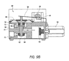
- FIG. 8 is a front view of the heating source of FIG. 7 .
- FIG. 8A is a cross-sectional view of the heating source of FIG. 8 taken along line A-A.
- FIG. 9 is a top view of the partially disassembled heating source of FIG. 7 .
- FIG. 9A is a cross-section of a heating source taken along line A-A of FIG. 9 .
- FIGS. 9 A 1 and 9 A 2 show the heating source of FIG. 9A in two different positions.
- FIGS. 9B and 9C are cross-sections of the heating source of FIG. 9A taken along line C-C in two different positions.
- FIGS. 10, 10A, and 10B illustrate perspective views of different embodiments of heating sources.
- FIGS. 11A and 11B are cross-sections of a heating source in two different positions.
- FIG. 12 is a cross-section of another heating source.
- FIG. 13 is a cross-section of still another heating source.
- FIG. 14 shows a perspective view of another embodiment of a heating source.
- FIG. 15 is a cross-section of the heating source of FIG. 14 .
- FIG. 16 is a cross-section of the heating source of FIG. 14 showing the pressure regulators.
- FIG. 17 is a cross-section of the heating source of FIG. 14 showing two valves.
- FIG. 1 illustrates one embodiment of a heater 100 .
- the heater 100 can be a vent-free infrared heater, a vent-free blue flame heater, or some other variety of heater, such as a direct vent heater. Some embodiments include boilers, stoves, dryers, fireplaces, gas logs, etc. Other configurations are also possible for the heater 100 .
- the heater 100 is configured to be mounted to a wall or a floor or to otherwise rest in a substantially static position. In other embodiments, the heater 100 is configured to move within a limited range. In still other embodiments, the heater 100 is portable.
- the heater 100 can comprise a housing 200 .
- the housing 200 can include metal or some other suitable material for providing structure to the heater 100 without melting or otherwise deforming in a heated environment.
- the housing 200 comprises a window 220 , one or more intake vents 240 and one or more outlet vents 260 . Heated air and/or radiant energy can pass through the window 220 . Air can flow into the heater 100 through the one or more intake vents 240 and heated air can flow out of the heater 100 through the outlet vents 260 .
- the heater 100 includes a regulator 120 .
- the regulator 120 can be coupled with an output line or intake line, conduit, or pipe 122 .
- the intake pipe 122 can be coupled with a heater control valve 130 , which, in some embodiments, includes a knob 132 .
- the heater control valve 130 is coupled to a fuel supply pipe 124 and an oxygen depletion sensor (ODS) pipe 126 , each of which can be coupled with a fluid flow controller 140 .
- the fluid flow controller 140 can be coupled with a first nozzle line 141 , a second nozzle line 142 , a first ODS line 143 , and a second ODS line 144 .
- the first and the second nozzle lines 141 , 142 are coupled with a nozzle 160
- the first and the second ODS lines 143 , 144 are coupled with an ODS 180
- the ODS comprises a thermocouple 182 , which can be coupled with the heater control valve 130
- an igniter line 184 which can be coupled with an igniter switch 186 .
- Each of the pipes 122 , 124 , and 126 and the lines 141 - 144 can define a fluid passageway or flow channel through which a fluid can move or flow.
- the heater 100 comprises a burner 190 .
- the ODS 180 can be mounted to the burner 190 , as shown.
- the nozzle 160 can be positioned to discharge a fluid, which may be a gas, liquid, or combination thereof into the burner 190 .
- a fluid which may be a gas, liquid, or combination thereof into the burner 190 .
- gas or liquid hereafter shall also include the possibility of a combination of a gas and a liquid.
- the term “fluid” is a broad term used in its ordinary sense, and includes materials or substances capable of fluid flow, such as gases, liquids, and combinations thereof.
- either a first or a second fluid is introduced into the heater 100 through the regulator 120 .
- the first or the second fluid proceeds from the regulator 120 through the intake pipe 122 to the heater control valve 130 .
- the heater control valve 130 can permit a portion of the first or the second fluid to flow into the fuel supply pipe 124 and permit another portion of the first or the second fluid to flow into the ODS pipe 126 . From the heater control valve 130 , the first or the second fluid can proceed to the fluid flow controller 140 .
- the fluid flow controller 140 is configured to channel the respective portions of the first fluid from the fuel supply pipe 124 to the first nozzle line 141 and from the ODS pipe 126 to the first ODS line 143 when the fluid flow controller 140 is in a first state, and is configured to channel the respective portions of the second fluid from the fuel supply pipe 124 to the second nozzle line 142 and from the ODS pipe 126 to the second ODS line 144 when the fluid flow controller 140 is in a second state.
- the fluid flow controller 140 when the fluid flow controller 140 is in the first state, a portion of the first fluid proceeds through the first nozzle line 141 , through the nozzle 160 and is delivered to the burner 190 , and a portion of the first fluid proceeds through the first ODS line 143 to the ODS 180 .
- a portion of the second fluid proceeds through the nozzle 160 and another portion proceeds to the ODS 180 .
- other configurations are also possible.
- the heating source 10 can be configured such that the installer of the gas appliance can connect the assembly to one of two fuels, such as either a supply of natural gas (NG) or a supply of propane (LP) and the assembly will desirably operate in the standard mode (with respect to efficiency and flame size and color) for either gas.
- NG natural gas
- LP propane
- a heating source 10 can comprise a fuel selector valve 3 .
- the fuel selector valve 3 can be used for selecting between two different fuels and for setting certain parameters, such as one or more flow paths, and/or a setting on one or more pressure regulators based on the desired and selected fuel.
- the fuel selector valve 3 can have a first mode configured to direct a flow of a first fuel (such as NG) in a first path through the fuel selector valve 3 and a second mode configured to direct a flow of a second fuel (such as LP) in a second path through the fuel selector valve 3 .
- the fuel selector valve 3 can further comprise first and second fuel source connections or hook-ups 12 , 14 .
- the fuel selector valve 3 can connect to one of two different fuel sources, each fuel source having a different type of fuel therein.
- one fuel source can be a cylinder of LP and another fuel source can be a NG fuel line in a house, connected to a city gas line.
- the first and second fuel source connections 12 , 14 can comprise any type of connection such as a threaded connection, a locking connection, an advance and twist type connection, etc.
- FIG. 3A An embodiment of a fuel selector valve 3 is shown in FIG. 3A with a housing 11 and a cover 20 . The cover has been removed in FIG. 3B revealing some of the internal components of the illustrated embodiment.
- a pressure regulator 16 is positioned within the housing such that fluid entering the fuel selector valve 3 via either the first or second fuel source connection 12 , 14 can be directed to the pressure regulator 16 .
- FIG. 3D shows a cross-section of the selector valve 3 showing the flow path between the fuel source connections and the pressure regulator. Fuel from the pressure regulator 16 can then flow to the outlet 18 , as can also be seen with reference to FIG. 3D . The fuel can then flow to various other components, such as a burner.
- the fuel selector valve 3 has two separate pressure regulators such that each fuel source connection directs fuel to a specific pressure regulator which can then travel to the outlet.
- the fuel selector valve 3 can be configured to select one or more flow paths through the fuel selector valve 3 and/or to set a parameter of the fuel selector valve.
- the fuel selector valve 3 can include one or more valves, where the position of the valve can determine one or more flow paths through the fuel selector valve 3 , such as a fluid exit or entry pathway.
- the fuel selector valve 3 can control certain parameters of the pressure regulator 16 .
- the fuel selector valve 3 can include one or more actuation members 22 , 24 .
- the actuation members 22 , 24 can be used for many purposes such as to select one or more flow paths through the fuel selector valve 3 and/or to set a parameter of the fuel selector valve.
- the one or more actuation members can be provided in the fuel selector valve 3 in many ways. As shown, the actuation members are spring loaded rods that can be advanced in a linear motion.
- An actuation member can be one or more of a linkage, a rod, an electric or mechanical button, a pin, a slider, a gear, a cam, etc.
- the actuation member 22 has an end 26 positioned within the first fuel source connection 12 .
- a connector 30 can be attached to the first fuel source connection 12 by advancing the connector into the first fuel source connection 12 . This can force the actuation member end 26 into the housing of the fuel selector valve 3 . This force then counteracts a spring force provided by a spring 32 to open a valve 34 .
- FIG. 4 A 1 shows the open valve 34 with the connector 30 attached to the first fuel source connection 12 .
- the connector 30 can be part of a fuel source to provide fuel to the heater assembly 10 .
- fuel from the fuel source can flow through the connector 30 and into the fuel selector valve 3 .
- fuel can flow into the first fuel source connection 12 , then to the pressure regulator 16 and finally out of the fuel selector valve 3 by way of outlet 18 ( FIG. 3A-3B ).
- the connector 30 can be connected to the second fuel source connection 14 . This can open the valve 36 by pressing on the end 28 of the second actuation member 24 . Fuel can then flow from the fuel source through the connector 30 into the fuel source connection 14 . The fuel can then flow to the pressure regulator 16 and out through outlet 18 .
- valves 34 , 36 can prevent fuel from exiting the fuel selector valve 3 undesirably, as well as preventing other undesirable materials from entering the fuel selector valve 3 .
- the fuel selector valve can utilize a cap or plug to block the unused fuel source connection. This may be in addition to or instead of one or more valves at the fuel source connections.
- the actuation member 24 does not include a valve at the fuel source connection 14 .
- the actuation member 24 can be in a position to control a parameter of the pressure regulator 16 .
- an arm 38 extends between the actuation member 24 and the pressure regulator 16 .
- the actuation member 24 can act on the arm, determining the position of the arm 38 . This position can be seen by comparing the position of the arm 38 in FIGS. 4 A 1 and 4 A 2 , as well as 4 B 1 and 4 B 2 . The position of the arm 38 can then determine the height (H 1 , H 3 ) of the spring 40 within the pressure regulator.
- the height H 1 of the spring when the diaphragm is in a first position shown in FIG. 4 B 1 is greater than the height H 3 of the spring when the spring is in the position shown in FIG. 4 B 2 .
- the arm 38 contacts a cap 41 that is connected to the spring 40 .
- the height of the spring 40 can be a factor in determining the force required to move the diaphragm 42 .
- the spring height can be used to preset the pressure settings of the pressure regulator.
- the spring can be tensioned to regulate the pressure of the incoming fuel depending on whether the first or second fuel source is utilized.
- the actuation member contacts the pressure regulator 16 directly, such as at the cap 41 , without the assistance of an arm or other device to set the regulating pressure of the pressure regulator.
- the pressure regulator 16 can be set to a first position as shown in FIG. 4 B 1 .
- the initial position can allow for flow control of the first fuel at an initial predetermined pressure or pressure range.
- the initial predetermined pressure or pressure range is lower than the second predetermined pressure or pressure range based on the second position as shown in FIG. 4 B 2 .
- the predetermined selected pressure can depend at least in part on the particular fuel used, and may desirably provide for safe and efficient fuel combustion and reduce, mitigate, or minimize undesirable emissions and pollution.
- the first pressure can be set to be within the range of about 3 inches of water column to about 6 inches of water column, including all values and sub-ranges therebetween.
- the threshold or flow-terminating pressure is about 3 inches of water column, about 4 inches of water column, about 5 inches of water column, or about 6 inches of water column.
- the second pressure can be set to be within the range of about 8 inches of water column to about 12 inches of water column, including all values and sub-ranges therebetween. In some embodiments, the second threshold or flow-terminating pressure is about equal to 8 inches of water column, about 9 inches of water column, about 10 inches of water column, about 11 inches of water column, or about 12 inches of water column.
- the first pressure, pressure range and threshold pressure are less than the second pressure, pressure range and threshold pressure. Stated differently, in some embodiments, when natural gas is the first fuel and propane is the second fuel, the second pressure, pressure range and threshold pressure are greater than the first pressure, pressure range and threshold pressure.
- the pressure regulator 16 can function in a similar manner to that discussed in U.S. application Ser. No. 11/443,484, filed May 30, 2006, now U.S. Pat. No. 7,607,426, incorporated herein by reference and made a part of this specification; with particular reference to the discussion on pressure regulators at columns 3-9 and FIGS. 3-7 of the issued patent.
- the pressure settings can be further adjusted by tensioning of a screw or other device 41 that allows for flow control of the fuel at a predetermined pressure or pressure range and selectively maintains an orifice open so that the fuel can flow through spring-loaded valve or valve assembly of the pressure regulator. If the pressure exceeds a threshold pressure, a plunger seat 43 can be pushed towards a seal ring 45 to seal off the orifice, thereby closing the pressure regulator.
- the fuel selector valve 3 can permit the flow of fuel from one or more pressure regulators, through the fuel selector valve 3 and into additional components.
- the additional components can be, for example, the heater control valve 130 , the fluid flow controller 140 , the nozzle 160 , etc.
- the additional components can comprise a control valve which comprises at least one of a manual valve, a thermostat valve, an AC solenoid, a DC solenoid and a flame adjustment motor.
- the additional components may or may not comprise part of the heating source 10 .
- the additional components can be configured to use the fuel, such as for combustion, and/or to direct one or more lines of fuel to other uses or areas of the heater 100 or other appliance.
- the actuation member 24 can have a varying or undulating surface that engages the arm 38 .
- the arm 38 can move with the varying surface thereby changing the position of the arm 38 .
- the arm 38 can be made from a resilient flexible material, such as metal or plastic, but can also be rigid.
- the arm as shown is a flexible material that can be moved and bent between positions with a resiliency to return to an unbent or less bent position.
- the arm can be a linkage, a pinned rotating arm, a member suspended between the actuation member and the pressure regulator, etc.
- the arm 38 can be elongate, have spring qualities, be biased upwards, be a bent metal arm or beam, etc.
- the actuation member 24 can have sections of different heights (H 2 , H 4 ).
- the actuation member 24 can include flat spots or sections with a diameter different than adjacent sections.
- the actuation member includes a flat portion 44 with a transition portion 46 that extends between the initial outer diameter of the cylindrical rod and the flat portion 44 .
- the portion 44 can have smaller diameter than the initial outer diameter of the rod.
- the rod can extend along a longitudinal axis and have a plurality of longitudinal cross-sections of different shapes.
- the actuation member 24 can be a type of cam and can also be shapes, besides cylindrical, and can have a surface that varies to provide different heights to the arm 38 for engaging the arm and setting the pressure at the pressure regulator 16 .
- FIG. 5A a schematic diagram of a heating source with a fuel selector valve 3 is illustrated.
- the illustrated fuel selector valve 3 can be similar to that described above with reference to FIGS. 3A - 4 B 2 .
- a fuel source can be connected to the fuel selector valve 3 via one of the fuel source connections 12 , 14 .
- the act of connecting the fuel source to the fuel selector valve 3 can set the pressure regulator to the desired pressure if it is not already at the desired pressure.
- selecting the proper fuel source connection can determine and sometimes set the pressure at the pressure regulator.
- one fuel source connection may allow fluid to flow through a default or preset path while the other fuel source connection may change the path including changing other characteristics of the system along the path such as the pressure regulator setting.
- both fuel source connections may change the path and/or other characteristics.
- the fuel selector valve 3 can permit the flow of fuel from the pressure regulator 16 through the fuel selector valve 3 and then into additional components.
- the additional components can be, for example, the heater control valve 130 , the fluid flow controller 140 , the nozzle 160 , etc.
- the additional components can comprise a control valve which comprises at least one of a manual valve, a thermostat valve, an AC solenoid, a DC solenoid and a flame adjustment motor.
- the additional components may or may not comprise part of the heating source 10 .
- the additional components can be configured to use the fuel, such as for combustion, and/or to direct one or more lines of fuel to other uses or areas of the heater 100 or other appliance.
- FIGS. 5B and 5C show additional embodiments of heating source where selecting the fuel source connection can set additional parameters.
- the fuel selector valve of FIG. 5B includes a valve 48 .
- the valve 48 has one inlet and two outlets, such that one outlet can be closed while the other is open.
- the valve 48 can have an initial position where one of the outlets is open and a secondary position where the other outlet is open.
- the selection of the fuel source connection can determine whether the valve is in the initial or secondary position. For example, selecting the first fuel source connection 12 can allow fuel flow through the initial configuration of the heating source, while selecting the second fuel source connection 14 can move the pressure regulator 16 and the valve 48 to their secondary configurations.
- the two outlets can both have separate open and closed positions with separate valves located at each outlet.
- the valve 48 can comprise two valves.
- the selection of the fuel source connection can determine which valve is opened. For example, selecting the first fuel source connection 12 can allow fuel flow through the initial configuration of the pressure regulator and can open the first valve at one of the outlets. Selecting the second fuel source connection 14 can move the pressure regulator 16 to its secondary configuration and open the second valve at the other of the outlets.
- FIG. 5C illustrates a fuel selector valve having two valves 48 , 50 .
- selecting the fuel source connection can also determine how the fuel flows through the valves 48 , 50 . For example, one selection can allow the fuel to follow the upward arrows, while the other selection can allow the fuel to follow the downward arrows.
- the fuel selector valve can also direct the fuel out of the fuel selector valve after the pressure regulator 16 , and then receive the fuel again. The fuel can be directed to other components 52 that then direct the fuel, or some of the fuel back to the fuel selector valve.
- the fuel selector valve show in FIG. 5B can also include other components 52 between the pressure regulator 16 and the valve 48 .
- the heating source can include the fuel selector valve and one or more of the other components.
- the other component 52 can preferably be a control valve.
- the control valve can comprise at least one of a manual valve, a thermostat valve, an AC solenoid, a DC solenoid and a flame adjustment motor.
- the control valve 52 can include two solenoids. Each solenoid can control the flow of fuel to one of the valves 48 , 50 .
- the valves can then direct fuel to additional components such as a pilot light or oxygen depletion sensor and to a nozzle.
- each line leaving the valve can be configured to direct a particular type of fuel to a component configured specific to that type of fuel.
- one valve may have two lines with each line connected to a different nozzle.
- the two nozzles can each have a different sized orifice and/or air hole and each can be configured for a particular fuel type.
- FIGS. 6A and 6B additional embodiments of heating sources are shown.
- the heating source of FIG. 6A is very similar to that shown in FIG. 5C .
- the fuel selector valve of FIG. 6A includes two pressure regulators 16 ′.
- the two pressure regulators 16 ′ can be preset to a particular pressure or pressure range. As there is only one line leading to each pressure regulator, the pressure regulators do not need to be changeable between two different pressures as discussed above with reference to FIGS. 5A-5C .
- either one of the fuel source connections 12 , 14 or both can determine and/or change a path through the fuel selector valve.
- each of valves 48 and 50 can comprise one valve or two valves as described above.
- FIG. 6B shows another embodiment where the control valve 52 returns two flows of fuel to the fuel selector valve. One flow of fuel is directed to a valve 48 and one flow passes through the fuel selector valve but does not have separate paths dependent on the fuel type.
- the fuel selector valve may also include valves in or near the fuel source connections 12 , 14 . This can help to control the flow of fuel into the fuel selector valve as has been previously discussed.
- FIGS. 7-9C another embodiment of heating source 10 is shown. It will be understood that parts of this heating source can function in a similar manner to the heating source shown and described with reference to FIGS. 3A - 4 B 2 . Thus, similar reference numbers are used.
- the pressure regulator 16 functions in the same way in both illustrated embodiments.
- the embodiment of FIGS. 7-9C is conceptually similar to the schematic diagram shown and described with reference to FIG. 5C .
- FIG. 7 it can be seen that a control valve 52 having two solenoids 54 , 56 is connected to the side of the fuel selector valve 3 .
- the fuel selector valve also includes two valves 48 , 50 .
- FIGS. 8 and 8A show the fuel selector valve 3 in relation to the control valve 52 .
- a fluid such as fuel, can flow from one of the fuel source connections 12 , 14 flows through the pressure regulator 16 to the control valve 52 .
- the fluid flow will first encounter the first solenoid 54 .
- the first solenoid 54 has a valve 58 that can control flow past the first solenoid 54 . When the valve 58 is open, fluid can flow to both the second solenoid 56 and to the valve 48 .
- the second solenoid 56 also has a valve 60 which can open or close to control fuel flow to the valve 50 .
- the valve 48 directs fuel to a pilot light or oxygen depletion sensor and the valve 50 directs fuel to a nozzle at a burner. Thus, it may be desirable direct fuel to be ignited at the pilot light first, before igniting or directing fuel to the burner.
- the control valve 52 can also control the amount of fuel flowing to burner.
- the control valve can also include a manual valve that allows for manual as well as, or instead of, automatic control by an electric valve, such as the two solenoids shown.
- selecting one of the first and second fuel source connections 12 , 14 can determine the flow path through the heating source.
- the actuation member 24 can move the valves 48 and 50 from an initial position to a secondary position in a manner similar to that described above with reference to the pressure regulator.
- the fuel selector valve 3 can be used for selecting between two different fuels and for setting certain parameters, such as one or more flow paths, and/or a setting on one or more pressure regulators based on the desired and selected fuel.
- the fuel selector valve 3 can have a first mode configured to direct a flow of a first fuel (such as NG) in a first path through the fuel selector valve 3 and a second mode configured to direct a flow of a second fuel (such as LP) in a second path through the fuel selector valve 3 .
- the fuel selector valve 3 can further comprise first and second fuel source connections or hook-ups 12 , 14 .
- the fuel selector valve 3 can connect to one of two different fuel sources, each fuel source having a different type of fuel therein.
- a pressure regulator 16 is positioned within the housing such that fluid entering the fuel selector valve 3 via either the first or second fuel source connection 12 , 14 can be directed to the pressure regulator 16 . Fuel from the pressure regulator 16 can then flow to the control valve 52 as discussed above.
- the fuel selector valve 3 has two separate pressure regulators such that each fuel source connection directs fuel to a specific pressure regulator.
- the fuel selector valve 3 can be configured to select one or more flow paths through the fuel selector valve 3 and/or to set a parameter of the fuel selector valve.
- the fuel selector valve 3 may include two valves 48 , 50 , where the position of the valve can determine a flow path through the fuel selector valve 3 .
- the fuel selector valve 3 can also control certain parameters of the pressure regulator 16 .
- the fuel selector valve 3 can include one or more actuation members 22 , 24 .
- the actuation members 22 , 24 can be used for many purposes such as to select one or more flow paths through the fuel selector valve 3 and/or to set a parameter of the fuel selector valve.
- the actuation members are spring loaded rods that can be advanced in a linear motion.
- the illustrated actuation member 22 has an end 26 positioned within the first fuel source connection 12 .
- a connector 30 can be attached to the first fuel source connection 12 by advancing the connector into the first fuel source connection 12 . This can force the actuation member end 26 into the housing of the fuel selector valve 3 . This force then counteracts a spring force provided by a spring 32 to open a valve 34 .
- FIG. 9 A 1 shows the open valve 34 with the connector 30 attached to the first fuel source connection 12 .
- the connector 30 can be part of a fuel source to provide fuel to the heater assembly 10 .
- fuel from the fuel source can flow into the first fuel source connection 12 , to the pressure regulator 16 , then to the control valve 52 and then to one or both of the valves 48 , 50 before finally leaving the fuel selector valve 3 .
- the connector 30 can be connected to the second fuel source connection 14 as shown in FIG. 9 A 2 . This can open the valve 36 by pressing on the end 28 of the second actuation member 24 . Fuel can then flow from the fuel source through the connector 30 into the fuel selector valve 3 and through the fuel selector valve 3 in the same manner as mentioned above.
- valves 34 , 36 can prevent fuel from exiting the fuel selector valve 3 undesirably, as well as preventing other undesirable materials from entering the fuel selector valve 3 .
- the fuel selector valve can utilize a cap or plug to block the unused fuel source connection. This may be in addition to or instead of one or more valves at the fuel source connections.
- the actuation member 24 does not include a valve at the fuel source connection 14 .
- the actuation member 24 can be in a position to control a parameter of the pressure regulator 16 , such as by an arm 38 that extends between the actuation member 24 and the pressure regulator 16 .
- the actuation member 24 can act on the arm, determining the position of the arm 38 .
- the position of the arm 38 can then determine the height of the spring 40 within the pressure regulator.
- the height of the spring 40 can be a factor in determining the force required to move the diaphragm 42 .
- the spring height can be used to set the pressure of the fluid flowing through the pressure regulator.
- the actuation member 24 can also control one or more valves, including valves 48 , 50 .
- the actuation member 24 can have a varying or undulating surface that engages the arms 38 as shown in FIGS. 9 A 1 - 9 A 2 .
- the arms 38 can move with the varying surface thereby changing the position of the arms 38 .
- the actuation member 24 can include flat spots or sections with a diameter different than adjacent sections. As can be seen, the actuation member includes flat portions 44 with transition portions 46 that extend between the initial outer diameter of the cylindrical rod and the flat portions 44 . Alternatively, the portion 44 can have a smaller diameter than the initial outer diameter of the rod.
- the rod can extend along a longitudinal axis and have a plurality of longitudinal cross-sections of different shapes.
- the actuation member 24 can be a type of cam and can also be shapes, besides cylindrical, and can have a surface that varies to provide different heights to the arms 38 for engaging the arms.
- valve 48 an embodiment of a valve 48 is shown.
- the valve 50 can function in a similar manner to that as will be described with reference to valve 48 .
- the valves can also function in other ways as will be understood by one of skill in the art.
- Valve 48 is shown having a valve body 62 that can control the fluid flow path and whether the flow exits the valve 48 through one of two outlets 70 , 72 .
- the valve body 62 can be seated against one of two different ledges 64 , 66 surrounding an opening to either open or close the pathway 71 , 73 to the respective outlet 70 , 72 .
- Fluid can enter the valve, such as from the control valve 52 as indicated by the dotted line.
- the position of the valve body 62 within the valve 48 can then determine whether the fluid exits via the first outlet 70 or the second outlet 72 .
- the valve body 62 can have a spring 32 to bias the valve body towards a first position as shown in FIG. 9B .
- the outlet 72 In the first position, the outlet 72 is open and outlet 70 is closed, thus fluid will flow through flow path 73 .
- the outlet 72 In the second position shown in FIG. 9C , the outlet 72 is closed and the outlet 70 is open, thus fluid will flow through flow path 71 .
- the valve body 62 can be made of one or more materials.
- the valve body 62 may include a solid core with a rubber or other elastic material to form the valve seat with the respective first or second ledge 64 , 66 .
- the valve body 62 can also engage the arm 38 so that the position of the valve body 62 is controlled by the actuation member 24 .
- the actuation member 24 can contact the valve body directly, without the use of an arm 38 .
- the arm 38 can take any form to allow the actuation member to control the position of the valve body within the valve 48 .
- the valve 48 can also include a diaphragm 68 .
- the diaphragm 68 can be different from the diaphragm 42 in the pressure regulator (FIGS. 4 B 1 and 4 B 2 ) in that the diaphragm 68 is generally not used for pressure regulation.
- the diaphragm 68 can be a sheet of a flexible material anchored at its periphery that is most often round in shape. It can serve as a flexible barrier that allows the valve to be actuated from the outside, while sealing the valve body 62 and keeping the contents, namely the fuel, within the fuel selector valve.
- FIG. 10 illustrates a perspective view of the heating source 10 where both the first valve 48 and the second valve 50 have two outlets and function in similar manners.
- the heating source 10 , valve 48 and valve 50 can all function in the same or a similar manner as that described with respect to FIGS. 7-9C .
- FIGS. 10A and 10B show heating sources where the first valve 48 is different from the second valve 50 .
- the valve 48 can be the same or similar to that described above and the valve 50 can be the same or similar to the valves described in more detail below.
- the heating source can include only one valve.
- the heating source may still include one or more outlets at the area that does not include a valve.
- FIGS. 11A and 11B show an embodiment of a valve 50 in cross-section.
- the illustrated valve 50 could be used in the heating source of FIG. 10A .
- the valve 50 has two channels or flow paths 78 , 80 and a valve body 62 ′ that is positioned to open and close only one of the flow paths 80 .
- the flow path 78 remains open so that when fuel is flowing from the control valve 52 to the valve 50 , it will flow through flow path 78 and it may also flow through flow path 80 .
- FIG. 11A shows the valve 50 with the valve body 62 ′ spaced away from the ledge 66 so that the valve and the flow path 80 are open.
- FIG. 11B shows the valve body 62 ′ seated at the ledge 66 so that the valve and the flow path 80 are closed.
- the flow path 78 remains open in both figures. There is also only one outlet 74 so both flow paths pass through the outlet 74 .
- FIG. 12 shows the valve 50 of FIG. 11A with a nozzle assembly 76 positioned within the outlet 74 .
- the nozzle assembly 76 has a center orifice 82 and an outer orifice 84 .
- the flow path 78 is in fluid communication with the center orifice 82 and the flow path 80 is in fluid communication with the outer orifice 84 .
- the orifices can be single orifices, or a plurality of orifices.
- the nozzle can have a single center orifice 82 and a plurality of orifices that surround the center orifice to make up the outer orifice 84 .
- FIG. 13 illustrates another embodiment of the fuel selector valve which is conceptually similar to the schematic diagram shown and described with reference to FIG. 6B .
- the fuel selector valve can have a valve 48 and then a separate flow path 86 .
- a control valve 52 can return two flows of fuel to the fuel selector valve, one of which to the valve 48 and one to the flow path 86 .
- the fuel in the flow path 86 can flow through the fuel selector valve without being controlled by have a valve 50 or without being directed down separate paths dependent on the fuel type. The fuel is simply directed out of the fuel selector valve.
- FIGS. 14-17 another embodiment of a heating source is shown which is conceptually similar to the schematic diagram shown and described with reference to FIG. 6A .
- both the first actuation member 22 ′ and the second actuation member 24 ′ are used to control valves at the inlets, but also the valves at the outlets of the fuel selector valve.
- the fuel selector valve includes two pressure regulators 16 ′, 16 ′′ as can be seen in FIG. 16 .
- the two pressure regulators 16 ′, 16 ′′ can be preset to a particular pressure or pressure range and each of the fuel source connections 12 , 14 can direct fluid flow to a specific pressure regulator.
- the pressure regulators do not need to be changeable between two different pressures as discussed previously.
- each pressure regulator 16 ′, 16 ′′ can be independently adjusted by tensioning of a screw or other device 41 that allows for flow control of the fuel at a predetermined pressure or pressure range and selectively maintains an orifice open so that the fuel can flow through spring-loaded valve or valve assembly of the pressure regulator. If the pressure exceeds a threshold pressure, a plunger seat 43 can be pushed towards a seal ring 45 to seal off the orifice, thereby closing the pressure regulator.
- valve 48 ′ can comprise two separate valves that are each separately controllable by either the first actuation member 22 ′ or the second actuation member 24 ′.
- the selection of the fuel source connection can determine which valve is opened. For example, selecting the first fuel source connection 12 and advancing the first actuation member 22 ′ can allow fuel flow through a preset pressure regulator 16 ′′ and can move the first valve body 62 ′ to the open position to allow flow through the outlet 70 .
- Selecting the second fuel source connection 14 and advancing the second actuation member 24 ′ can allow fuel flow through a preset pressure regulator 16 ′ and can move the second valve body 62 ′′ to the open position to allow flow through the outlet 72 . It is anticipated that only one of the fuel source connections will be selected, though it is possible that in certain configurations, both fuel source connections could be in use.
- the fuel selector valve may also include valves in or near the fuel source connections 12 , 14 . This can help to control the flow of fuel into the fuel selector valve as has been previously discussed.
- valve 50 ′ can be similar to valve 48 ′ or can have a different configuration.
- the valve 50 ′ may have one or two outlets and it may include a nozzle in the one outlet.
- Each of the fuel selector valves described herein can be used with a pilot light or oxygen depletion sensor, a nozzle, and a burner to form part of a heater or other gas appliance.
- the different configurations of valves and controls such as by the actuation members can allow the fuel selector valve to be used in different types of systems.
- the fuel selector valve can be used in a dual fuel heater system with separate ODS and nozzles for each fuel.
- the fuel selector valve can also be used with nozzles and ODS that are pressure sensitive so that can be only one nozzle, one ODS, or one line leading to the various components from the fuel selector valve.
- a heater assembly can be uses with one of a first fuel type or a second fuel type different than the first.
- the heater assembly can include a pressure regulator having a first position and a second position and a housing having first and second fuel hook-ups.
- the first fuel hook-up can be used for connecting the first fuel type to the heater assembly and the second hook-up can be used for connecting the second fuel type to the heater assembly.
- An actuation member can be positioned such that one end is located within the second fuel hook-up.
- the actuation member can have a first position and a second position, such that connecting a fuel source to the heater assembly at the second fuel hook-up moves the actuation member from the first position to the second position. This can cause the pressure regulator to move from its first position to its second position.
- the pressure regulator in the second position can be configured to regulate a fuel flow of the second fuel type within a predetermined range.
- the heater assembly may also include one or more of a second pressure regulator, a second actuation member, and one or more arms extending between the respective actuation member and pressure regulator.
- the one or more arms can be configured to establish a compressible height of a pressure regulator spring within the pressure regulator.
- a heater assembly can be used with one of a first fuel type or a second fuel type different than the first.
- the heater assembly can include at least one pressure regulator and a housing.
- the housing can comprise a first fuel hook-up for connecting the first fuel type to the heater assembly, and a second fuel hook-up for connecting the second fuel type to the heater assembly.
- the housing can also include a first inlet, a first outlet, a second outlet configured with an open position and a closed position, and a first valve configured to open and close the second outlet.
- a first actuation member having an end located within the second fuel hook-up and having a first position and a second position can be configured such that connecting a fuel source to the heater assembly at the second fuel hook-up moves the actuation member from the first position to the second position which causes the first valve to open the second outlet, the second outlet being in fluid communication with the second fuel hook-up.
- the first actuation member can be further configured such that connecting the fuel source to the heater assembly at the second fuel hook-up moves the first actuation member from the first position to the second position which causes the at least one pressure regulator to move from a first position to a second position, wherein the at least one pressure regulator in the second position is configured to regulate a fuel flow of the second fuel type within a predetermined range.
- the at least one pressure regulator can comprises first and second pressure regulators, the first pressure regulator being in fluid communication with the first fuel hook-up and the second pressure regulator being in fluid communication with the second fuel hook-up.
- first valve can be configured to open and close both the first and second outlets or there can be a second valve configured to open and close the first outlet.
- the housing may include addition, inlets, outlets and valves. Also a second actuation member may be used positioned within the first fuel hook-up.
Abstract
A heater assembly can be used with a gas appliance. The gas appliance can be a dual fuel appliance for use with one of a first fuel type or a second fuel type different than the first. The heater assembly can include at least one pressure regulator, a housing, and an actuation member. The housing has a first fuel hook-up for connecting the first fuel type to the heater assembly, a second fuel hook-up for connecting the second fuel type to the heater assembly, and an internal valve. The actuation member can control the position of the internal valve based on whether the first or the second fuel hook-up is used.
Description
This application is a continuation of U.S. application Ser. No. 13/311,402, filed Dec. 5, 2011, now U.S. Pat. No. 8,915,239 which claims priority to Chinese Patent Appl. No. 201110320667.6, filed Oct. 20, 2011. All of the above applications are hereby incorporated by reference in their entirety into this specification. Any and all applications for which a foreign or domestic priority claim is identified in the Application Data Sheet as filed with the present application, are hereby incorporated by reference under 37 CFR 1.57.
Field of the Invention
Certain embodiments disclosed herein relate generally to a heating apparatus for use in a gas appliance particularly adapted for dual fuel use. The heating apparatus can be, can be a part of, and can be used in or with many different appliances, including, but not limited to: heaters, boilers, dryers, washing machines, ovens, fireplaces, stoves, water heaters, barbeques, etc.
Description of the Related Art
Many varieties of appliances, such as heaters, boilers, dryers, washing machines, ovens, fireplaces, stoves, and other heat-producing devices utilize pressurized, combustible fuels. Some such devices operate with liquid propane, while others operate with natural gas. However, such devices and certain components thereof have various limitations and disadvantages. Therefore, there exists a constant need for improvement in appliances and components to be used in appliances.
A heater assembly can be used with one of a first fuel type or a second fuel type different than the first. The heater assembly can include at least one pressure regulator, a housing, and an actuation member. The housing has a first fuel hook-up for connecting the first fuel type to the heater assembly, a second fuel hook-up for connecting the second fuel type to the heater assembly, and an internal valve. The actuation member can control the position of the internal valve based on whether the first or the second fuel hook-up is used or selected.
A heater assembly according to some embodiments can comprise a pressure regulator having a first position and a second position, a housing having first and second fuel hook-ups, and an actuation member. The first fuel hook-up can be for connecting a first fuel type to the heater assembly and the second hook-up can be for connecting a second fuel type to the heater assembly. The actuation member can have an end located within the second fuel hook-up and a first position and a second position. The actuation member can be configured such that connecting a fuel source to the heater assembly at the second fuel hook-up moves the actuation member from the first position to the second position which causes the pressure regulator to move from the first position to the second position. The pressure regulator in the second position can be configured to regulate a fuel flow of the second fuel type within a predetermined range.
The heater assembly can have a pressure regulator where the first position is configured to regulate a fuel flow of the first fuel type within a predetermined range different than the predetermined range for the second fuel type. Alternatively, the heater assembly can include a second pressure regulator configured to regulate a fuel flow of the first fuel type within a predetermined range different than the predetermined range for the second fuel type.
The actuation member can comprise a rod configured for linear advancement from the first position to the second position. The rod can extend along a longitudinal axis and have a plurality of longitudinal cross-sections of different shapes. A first section of the actuation member can be associated with the pressure regulator in the first position and a second section of the actuation member can be associated with the pressure regulator in the second position, the first section having a longitudinal cross-section of a different shape than the second section.
The heater assembly can further include additional valves that can also be controlled with the actuation member. The heater assembly can also include an additional actuation member.
In some embodiments, a heater assembly can comprise at least one pressure regulator, a housing, and a first actuation member. The housing can include a first fuel hook-up for connecting the first fuel type to the heater assembly, a second fuel hook-up for connecting the second fuel type to the heater assembly, a first inlet, a first outlet, a second outlet configured with an open position and a closed position, and a first valve configured to open and close the second outlet. The first actuation member can have an end located within the second fuel hook-up and a first position and a second position. The first actuation member can be configured such that connecting a fuel source to the heater assembly at the second fuel hook-up moves the actuation member from the first position to the second position which causes the first valve to open the second outlet, the second outlet being in fluid communication with the second fuel hook-up.
The first actuation member can be further configured such that connecting the fuel source to the heater assembly at the second fuel hook-up moves the first actuation member from the first position to the second position which causes the at least one pressure regulator to move from a first position to a second position, wherein the at least one pressure regulator in the second position is configured to regulate a fuel flow of the second fuel type within a predetermined range.
These and other features, aspects and advantages are described below with reference to the drawings, which are intended to illustrate but not to limit the invention. In the drawings, like reference characters denote corresponding features consistently throughout similar embodiments.
FIGS. 4A1 and 4A2 show the heating source of FIG. 4A in two different positions.
FIGS. 4B1 and 4B2 are cross-sections of the heating source of FIG. 4A taken along line B-B in two different positions.
FIGS. 9A1 and 9A2 show the heating source of FIG. 9A in two different positions.
Many varieties of space heaters, fireplaces, stoves, ovens, boilers, fireplace inserts, gas logs, and other heat-producing devices employ combustible fuels, such as liquid propane and natural gas. These devices generally are designed to operate with a single fuel type at a specific pressure. For example, as one having skill in the art would appreciate, some gas heaters that are configured to be installed on a wall or a floor operate with natural gas at a pressure in a range from about 3 inches of water column to about 6 inches of water column, while others operate with liquid propane at a pressure in a range from about 8 inches of water column to about 12 inches of water column.
In many instances, the operability of such devices with only a single fuel source is disadvantageous for distributors, retailers, and/or consumers. For example, retail stores often try to predict the demand for natural gas units versus liquid propane units over a given season, and accordingly stock their shelves and/or warehouses with a percentage of each variety of device. Should such predictions prove incorrect, stores can be left with unsold units when the demand for one type of unit was less than expected, while some potential customers can be left waiting through shipping delays or even be turned away empty-handed when the demand for one type of unit was greater than expected. Either case can result in financial and other costs to the stores. Additionally, some consumers can be disappointed to discover that the styles or models of stoves, fireplaces or other device, with which they wish to improve their homes, are incompatible with the fuel sources with which their homes are serviced.
Certain advantageous embodiments disclosed herein reduce or eliminate these and other problems associated with devices having heating sources that operate with only a single type of fuel source. Furthermore, although certain of the embodiments described hereafter are presented in the context of vent-free heating systems, the apparatus and devices disclosed and enabled herein can benefit a wide variety of other applications and appliances.
The heater 100 can comprise a housing 200. The housing 200 can include metal or some other suitable material for providing structure to the heater 100 without melting or otherwise deforming in a heated environment. In the illustrated embodiment, the housing 200 comprises a window 220, one or more intake vents 240 and one or more outlet vents 260. Heated air and/or radiant energy can pass through the window 220. Air can flow into the heater 100 through the one or more intake vents 240 and heated air can flow out of the heater 100 through the outlet vents 260.
With reference to FIG. 2 , in certain embodiments, the heater 100 includes a regulator 120. The regulator 120 can be coupled with an output line or intake line, conduit, or pipe 122. The intake pipe 122 can be coupled with a heater control valve 130, which, in some embodiments, includes a knob 132. As illustrated, the heater control valve 130 is coupled to a fuel supply pipe 124 and an oxygen depletion sensor (ODS) pipe 126, each of which can be coupled with a fluid flow controller 140. The fluid flow controller 140 can be coupled with a first nozzle line 141, a second nozzle line 142, a first ODS line 143, and a second ODS line 144. In some embodiments, the first and the second nozzle lines 141, 142 are coupled with a nozzle 160, and the first and the second ODS lines 143, 144 are coupled with an ODS 180. In some embodiments, the ODS comprises a thermocouple 182, which can be coupled with the heater control valve 130, and an igniter line 184, which can be coupled with an igniter switch 186. Each of the pipes 122, 124, and 126 and the lines 141-144 can define a fluid passageway or flow channel through which a fluid can move or flow.
In some embodiments, including the illustrated embodiment, the heater 100 comprises a burner 190. The ODS 180 can be mounted to the burner 190, as shown. The nozzle 160 can be positioned to discharge a fluid, which may be a gas, liquid, or combination thereof into the burner 190. For purposes of brevity, recitation of the term “gas or liquid” hereafter shall also include the possibility of a combination of a gas and a liquid. In addition, as used herein, the term “fluid” is a broad term used in its ordinary sense, and includes materials or substances capable of fluid flow, such as gases, liquids, and combinations thereof.
Where the heater 100 is a dual fuel heater, either a first or a second fluid is introduced into the heater 100 through the regulator 120. Still referring to FIG. 2 , the first or the second fluid proceeds from the regulator 120 through the intake pipe 122 to the heater control valve 130. The heater control valve 130 can permit a portion of the first or the second fluid to flow into the fuel supply pipe 124 and permit another portion of the first or the second fluid to flow into the ODS pipe 126. From the heater control valve 130, the first or the second fluid can proceed to the fluid flow controller 140. In many embodiments, the fluid flow controller 140 is configured to channel the respective portions of the first fluid from the fuel supply pipe 124 to the first nozzle line 141 and from the ODS pipe 126 to the first ODS line 143 when the fluid flow controller 140 is in a first state, and is configured to channel the respective portions of the second fluid from the fuel supply pipe 124 to the second nozzle line 142 and from the ODS pipe 126 to the second ODS line 144 when the fluid flow controller 140 is in a second state.
In certain embodiments, when the fluid flow controller 140 is in the first state, a portion of the first fluid proceeds through the first nozzle line 141, through the nozzle 160 and is delivered to the burner 190, and a portion of the first fluid proceeds through the first ODS line 143 to the ODS 180. Similarly, when the fluid flow controller 140 is in the second state, a portion of the second fluid proceeds through the nozzle 160 and another portion proceeds to the ODS 180. As discussed in more detail below, other configurations are also possible.
A heating assembly or heating source 10 that can be used with the heater 100, or other gas appliances, will now be described. The heating source 10 can be configured such that the installer of the gas appliance can connect the assembly to one of two fuels, such as either a supply of natural gas (NG) or a supply of propane (LP) and the assembly will desirably operate in the standard mode (with respect to efficiency and flame size and color) for either gas.
Looking at FIGS. 3A -4B2, a heating source 10 can comprise a fuel selector valve 3. The fuel selector valve 3 can be used for selecting between two different fuels and for setting certain parameters, such as one or more flow paths, and/or a setting on one or more pressure regulators based on the desired and selected fuel. The fuel selector valve 3 can have a first mode configured to direct a flow of a first fuel (such as NG) in a first path through the fuel selector valve 3 and a second mode configured to direct a flow of a second fuel (such as LP) in a second path through the fuel selector valve 3.
The fuel selector valve 3 can further comprise first and second fuel source connections or hook- ups 12, 14. The fuel selector valve 3 can connect to one of two different fuel sources, each fuel source having a different type of fuel therein. For example, one fuel source can be a cylinder of LP and another fuel source can be a NG fuel line in a house, connected to a city gas line. The first and second fuel source connections 12, 14 can comprise any type of connection such as a threaded connection, a locking connection, an advance and twist type connection, etc.
An embodiment of a fuel selector valve 3 is shown in FIG. 3A with a housing 11 and a cover 20. The cover has been removed in FIG. 3B revealing some of the internal components of the illustrated embodiment. A pressure regulator 16 is positioned within the housing such that fluid entering the fuel selector valve 3 via either the first or second fuel source connection 12, 14 can be directed to the pressure regulator 16. FIG. 3D shows a cross-section of the selector valve 3 showing the flow path between the fuel source connections and the pressure regulator. Fuel from the pressure regulator 16 can then flow to the outlet 18, as can also be seen with reference to FIG. 3D . The fuel can then flow to various other components, such as a burner. In some embodiments, the fuel selector valve 3 has two separate pressure regulators such that each fuel source connection directs fuel to a specific pressure regulator which can then travel to the outlet.
The fuel selector valve 3 can be configured to select one or more flow paths through the fuel selector valve 3 and/or to set a parameter of the fuel selector valve. For example, the fuel selector valve 3 can include one or more valves, where the position of the valve can determine one or more flow paths through the fuel selector valve 3, such as a fluid exit or entry pathway. As another example, the fuel selector valve 3 can control certain parameters of the pressure regulator 16.
With reference to FIGS. 4 -4A2, it can be seen that the fuel selector valve 3 can include one or more actuation members 22, 24. The actuation members 22, 24 can be used for many purposes such as to select one or more flow paths through the fuel selector valve 3 and/or to set a parameter of the fuel selector valve. The one or more actuation members can be provided in the fuel selector valve 3 in many ways. As shown, the actuation members are spring loaded rods that can be advanced in a linear motion. An actuation member can be one or more of a linkage, a rod, an electric or mechanical button, a pin, a slider, a gear, a cam, etc.
As shown, the actuation member 22 has an end 26 positioned within the first fuel source connection 12. A connector 30 can be attached to the first fuel source connection 12 by advancing the connector into the first fuel source connection 12. This can force the actuation member end 26 into the housing of the fuel selector valve 3. This force then counteracts a spring force provided by a spring 32 to open a valve 34.
FIG. 4A1 shows the open valve 34 with the connector 30 attached to the first fuel source connection 12. The connector 30 can be part of a fuel source to provide fuel to the heater assembly 10. With the valve 34 in the open position, fuel from the fuel source can flow through the connector 30 and into the fuel selector valve 3. In particular, as shown, fuel can flow into the first fuel source connection 12, then to the pressure regulator 16 and finally out of the fuel selector valve 3 by way of outlet 18 (FIG. 3A-3B ).
Alternatively, the connector 30 can be connected to the second fuel source connection 14. This can open the valve 36 by pressing on the end 28 of the second actuation member 24. Fuel can then flow from the fuel source through the connector 30 into the fuel source connection 14. The fuel can then flow to the pressure regulator 16 and out through outlet 18.
The presence of two valves 34, 36, one at each fuel source connection 12, 14, can prevent fuel from exiting the fuel selector valve 3 undesirably, as well as preventing other undesirable materials from entering the fuel selector valve 3. In some embodiments, the fuel selector valve can utilize a cap or plug to block the unused fuel source connection. This may be in addition to or instead of one or more valves at the fuel source connections. For example, in some embodiments the actuation member 24 does not include a valve at the fuel source connection 14.
In addition to or instead of providing a valve 36 at the inlet or fuel source connection 14, the actuation member 24 can be in a position to control a parameter of the pressure regulator 16. Referring back to FIGS. 3B and 4 , it can be seen that an arm 38 extends between the actuation member 24 and the pressure regulator 16. The actuation member 24 can act on the arm, determining the position of the arm 38. This position can be seen by comparing the position of the arm 38 in FIGS. 4A1 and 4A2, as well as 4B1 and 4B2. The position of the arm 38 can then determine the height (H1, H3) of the spring 40 within the pressure regulator. That is, though the length of the spring is constant, the height H1 of the spring when the diaphragm is in a first position shown in FIG. 4B1 is greater than the height H3 of the spring when the spring is in the position shown in FIG. 4B2. As shown, the arm 38 contacts a cap 41 that is connected to the spring 40. The height of the spring 40 can be a factor in determining the force required to move the diaphragm 42. The spring height can be used to preset the pressure settings of the pressure regulator. Thus, the spring can be tensioned to regulate the pressure of the incoming fuel depending on whether the first or second fuel source is utilized.
In another embodiment, the actuation member contacts the pressure regulator 16 directly, such as at the cap 41, without the assistance of an arm or other device to set the regulating pressure of the pressure regulator.
The pressure regulator 16 can be set to a first position as shown in FIG. 4B1. The initial position can allow for flow control of the first fuel at an initial predetermined pressure or pressure range. The initial predetermined pressure or pressure range is lower than the second predetermined pressure or pressure range based on the second position as shown in FIG. 4B2. For example, the predetermined selected pressure can depend at least in part on the particular fuel used, and may desirably provide for safe and efficient fuel combustion and reduce, mitigate, or minimize undesirable emissions and pollution. In some embodiments, the first pressure can be set to be within the range of about 3 inches of water column to about 6 inches of water column, including all values and sub-ranges therebetween. In some embodiments, the threshold or flow-terminating pressure is about 3 inches of water column, about 4 inches of water column, about 5 inches of water column, or about 6 inches of water column.
In some embodiments, the second pressure can be set to be within the range of about 8 inches of water column to about 12 inches of water column, including all values and sub-ranges therebetween. In some embodiments, the second threshold or flow-terminating pressure is about equal to 8 inches of water column, about 9 inches of water column, about 10 inches of water column, about 11 inches of water column, or about 12 inches of water column.
When natural gas is the first fuel and propane is the second fuel, the first pressure, pressure range and threshold pressure are less than the second pressure, pressure range and threshold pressure. Stated differently, in some embodiments, when natural gas is the first fuel and propane is the second fuel, the second pressure, pressure range and threshold pressure are greater than the first pressure, pressure range and threshold pressure.
The pressure regulator 16 can function in a similar manner to that discussed in U.S. application Ser. No. 11/443,484, filed May 30, 2006, now U.S. Pat. No. 7,607,426, incorporated herein by reference and made a part of this specification; with particular reference to the discussion on pressure regulators at columns 3-9 and FIGS. 3-7 of the issued patent.
The pressure settings can be further adjusted by tensioning of a screw or other device 41 that allows for flow control of the fuel at a predetermined pressure or pressure range and selectively maintains an orifice open so that the fuel can flow through spring-loaded valve or valve assembly of the pressure regulator. If the pressure exceeds a threshold pressure, a plunger seat 43 can be pushed towards a seal ring 45 to seal off the orifice, thereby closing the pressure regulator.
The fuel selector valve 3 can permit the flow of fuel from one or more pressure regulators, through the fuel selector valve 3 and into additional components. The additional components can be, for example, the heater control valve 130, the fluid flow controller 140, the nozzle 160, etc. In some embodiments, the additional components can comprise a control valve which comprises at least one of a manual valve, a thermostat valve, an AC solenoid, a DC solenoid and a flame adjustment motor. In various embodiments, the additional components may or may not comprise part of the heating source 10. The additional components can be configured to use the fuel, such as for combustion, and/or to direct one or more lines of fuel to other uses or areas of the heater 100 or other appliance.
Returning now to FIGS. 4A1-4B2, the functioning of the arm 38 and the actuation member 24 will be described in more detail. The actuation member 24 can have a varying or undulating surface that engages the arm 38. The arm 38 can move with the varying surface thereby changing the position of the arm 38. The arm 38 can be made from a resilient flexible material, such as metal or plastic, but can also be rigid. The arm as shown is a flexible material that can be moved and bent between positions with a resiliency to return to an unbent or less bent position. In other embodiments, the arm can be a linkage, a pinned rotating arm, a member suspended between the actuation member and the pressure regulator, etc. The arm 38 can be elongate, have spring qualities, be biased upwards, be a bent metal arm or beam, etc.
The actuation member 24 can have sections of different heights (H2, H4). For example, the actuation member 24 can include flat spots or sections with a diameter different than adjacent sections. As can be seen, the actuation member includes a flat portion 44 with a transition portion 46 that extends between the initial outer diameter of the cylindrical rod and the flat portion 44. Alternatively, the portion 44 can have smaller diameter than the initial outer diameter of the rod. The rod can extend along a longitudinal axis and have a plurality of longitudinal cross-sections of different shapes. The actuation member 24 can be a type of cam and can also be shapes, besides cylindrical, and can have a surface that varies to provide different heights to the arm 38 for engaging the arm and setting the pressure at the pressure regulator 16.
Looking now to FIG. 5A , a schematic diagram of a heating source with a fuel selector valve 3 is illustrated. The illustrated fuel selector valve 3 can be similar to that described above with reference to FIGS. 3A -4B2. A fuel source can be connected to the fuel selector valve 3 via one of the fuel source connections 12, 14. The act of connecting the fuel source to the fuel selector valve 3 can set the pressure regulator to the desired pressure if it is not already at the desired pressure. Thus, selecting the proper fuel source connection can determine and sometimes set the pressure at the pressure regulator. It will be understood that one fuel source connection may allow fluid to flow through a default or preset path while the other fuel source connection may change the path including changing other characteristics of the system along the path such as the pressure regulator setting. In some embodiments, both fuel source connections may change the path and/or other characteristics.
The fuel selector valve 3 can permit the flow of fuel from the pressure regulator 16 through the fuel selector valve 3 and then into additional components. The additional components can be, for example, the heater control valve 130, the fluid flow controller 140, the nozzle 160, etc. In some embodiments, the additional components can comprise a control valve which comprises at least one of a manual valve, a thermostat valve, an AC solenoid, a DC solenoid and a flame adjustment motor. In various embodiments, the additional components may or may not comprise part of the heating source 10. The additional components can be configured to use the fuel, such as for combustion, and/or to direct one or more lines of fuel to other uses or areas of the heater 100 or other appliance.
In other embodiments, the two outlets can both have separate open and closed positions with separate valves located at each outlet. Thus, the valve 48 can comprise two valves. The selection of the fuel source connection can determine which valve is opened. For example, selecting the first fuel source connection 12 can allow fuel flow through the initial configuration of the pressure regulator and can open the first valve at one of the outlets. Selecting the second fuel source connection 14 can move the pressure regulator 16 to its secondary configuration and open the second valve at the other of the outlets.
The other component 52 can preferably be a control valve. In some embodiments, the control valve can comprise at least one of a manual valve, a thermostat valve, an AC solenoid, a DC solenoid and a flame adjustment motor. For example the control valve 52 can include two solenoids. Each solenoid can control the flow of fuel to one of the valves 48, 50. The valves can then direct fuel to additional components such as a pilot light or oxygen depletion sensor and to a nozzle. In some embodiments, each line leaving the valve can be configured to direct a particular type of fuel to a component configured specific to that type of fuel. For example, one valve may have two lines with each line connected to a different nozzle. The two nozzles can each have a different sized orifice and/or air hole and each can be configured for a particular fuel type.
Turning now to FIGS. 6A and 6B , additional embodiments of heating sources are shown. The heating source of FIG. 6A is very similar to that shown in FIG. 5C . One difference is that the fuel selector valve of FIG. 6A includes two pressure regulators 16′. The two pressure regulators 16′ can be preset to a particular pressure or pressure range. As there is only one line leading to each pressure regulator, the pressure regulators do not need to be changeable between two different pressures as discussed above with reference to FIGS. 5A-5C . In addition, similar to FIGS. 5B and 5C , either one of the fuel source connections 12, 14 or both can determine and/or change a path through the fuel selector valve. For example, each of valves 48 and 50 can comprise one valve or two valves as described above.
In each of the embodiments shown in FIGS. 5A-6B , the fuel selector valve may also include valves in or near the fuel source connections 12, 14. This can help to control the flow of fuel into the fuel selector valve as has been previously discussed.
Turning now to FIGS. 7-9C , another embodiment of heating source 10 is shown. It will be understood that parts of this heating source can function in a similar manner to the heating source shown and described with reference to FIGS. 3A -4B2. Thus, similar reference numbers are used. For example, the pressure regulator 16 functions in the same way in both illustrated embodiments. In addition, the embodiment of FIGS. 7-9C is conceptually similar to the schematic diagram shown and described with reference to FIG. 5C .
Looking to FIG. 7 , it can be seen that a control valve 52 having two solenoids 54, 56 is connected to the side of the fuel selector valve 3. The fuel selector valve also includes two valves 48, 50. FIGS. 8 and 8A show the fuel selector valve 3 in relation to the control valve 52. A fluid, such as fuel, can flow from one of the fuel source connections 12, 14 flows through the pressure regulator 16 to the control valve 52. The fluid flow will first encounter the first solenoid 54. The first solenoid 54 has a valve 58 that can control flow past the first solenoid 54. When the valve 58 is open, fluid can flow to both the second solenoid 56 and to the valve 48. The second solenoid 56 also has a valve 60 which can open or close to control fuel flow to the valve 50. In some embodiments, the valve 48 directs fuel to a pilot light or oxygen depletion sensor and the valve 50 directs fuel to a nozzle at a burner. Thus, it may be desirable direct fuel to be ignited at the pilot light first, before igniting or directing fuel to the burner. The control valve 52 can also control the amount of fuel flowing to burner. In some embodiments, the control valve can also include a manual valve that allows for manual as well as, or instead of, automatic control by an electric valve, such as the two solenoids shown.
As discussed, selecting one of the first and second fuel source connections 12, 14 can determine the flow path through the heating source. In particular, the actuation member 24 can move the valves 48 and 50 from an initial position to a secondary position in a manner similar to that described above with reference to the pressure regulator.
The fuel selector valve 3 can be used for selecting between two different fuels and for setting certain parameters, such as one or more flow paths, and/or a setting on one or more pressure regulators based on the desired and selected fuel. The fuel selector valve 3 can have a first mode configured to direct a flow of a first fuel (such as NG) in a first path through the fuel selector valve 3 and a second mode configured to direct a flow of a second fuel (such as LP) in a second path through the fuel selector valve 3.
The fuel selector valve 3 can further comprise first and second fuel source connections or hook- ups 12, 14. The fuel selector valve 3 can connect to one of two different fuel sources, each fuel source having a different type of fuel therein.
A pressure regulator 16 is positioned within the housing such that fluid entering the fuel selector valve 3 via either the first or second fuel source connection 12, 14 can be directed to the pressure regulator 16. Fuel from the pressure regulator 16 can then flow to the control valve 52 as discussed above. In some embodiments, the fuel selector valve 3 has two separate pressure regulators such that each fuel source connection directs fuel to a specific pressure regulator.
The fuel selector valve 3 can be configured to select one or more flow paths through the fuel selector valve 3 and/or to set a parameter of the fuel selector valve. For example, the fuel selector valve 3 may include two valves 48, 50, where the position of the valve can determine a flow path through the fuel selector valve 3. The fuel selector valve 3 can also control certain parameters of the pressure regulator 16.
With reference to FIGS. 9 -9A2, it can be seen that the fuel selector valve 3 can include one or more actuation members 22, 24. The actuation members 22, 24 can be used for many purposes such as to select one or more flow paths through the fuel selector valve 3 and/or to set a parameter of the fuel selector valve. As shown, the actuation members are spring loaded rods that can be advanced in a linear motion.
The illustrated actuation member 22 has an end 26 positioned within the first fuel source connection 12. A connector 30 can be attached to the first fuel source connection 12 by advancing the connector into the first fuel source connection 12. This can force the actuation member end 26 into the housing of the fuel selector valve 3. This force then counteracts a spring force provided by a spring 32 to open a valve 34.
FIG. 9A1 shows the open valve 34 with the connector 30 attached to the first fuel source connection 12. The connector 30 can be part of a fuel source to provide fuel to the heater assembly 10. With the valve 34 in the open position, fuel from the fuel source can flow into the first fuel source connection 12, to the pressure regulator 16, then to the control valve 52 and then to one or both of the valves 48, 50 before finally leaving the fuel selector valve 3.
Alternatively, the connector 30 can be connected to the second fuel source connection 14 as shown in FIG. 9A2. This can open the valve 36 by pressing on the end 28 of the second actuation member 24. Fuel can then flow from the fuel source through the connector 30 into the fuel selector valve 3 and through the fuel selector valve 3 in the same manner as mentioned above.
The presence of two valves 34, 36, one at each fuel source connection 12, 14, can prevent fuel from exiting the fuel selector valve 3 undesirably, as well as preventing other undesirable materials from entering the fuel selector valve 3. In some embodiments, the fuel selector valve can utilize a cap or plug to block the unused fuel source connection. This may be in addition to or instead of one or more valves at the fuel source connections. For example, in some embodiments the actuation member 24 does not include a valve at the fuel source connection 14.
In addition to, or instead of, providing a valve 36 at the inlet or fuel source connection 14, the actuation member 24 can be in a position to control a parameter of the pressure regulator 16, such as by an arm 38 that extends between the actuation member 24 and the pressure regulator 16. The actuation member 24 can act on the arm, determining the position of the arm 38. The position of the arm 38 can then determine the height of the spring 40 within the pressure regulator. The height of the spring 40 can be a factor in determining the force required to move the diaphragm 42. The spring height can be used to set the pressure of the fluid flowing through the pressure regulator.
In addition to controlling the pressure regulator, the actuation member 24 can also control one or more valves, including valves 48, 50. The actuation member 24 can have a varying or undulating surface that engages the arms 38 as shown in FIGS. 9A1-9A2. The arms 38 can move with the varying surface thereby changing the position of the arms 38.
The actuation member 24 can include flat spots or sections with a diameter different than adjacent sections. As can be seen, the actuation member includes flat portions 44 with transition portions 46 that extend between the initial outer diameter of the cylindrical rod and the flat portions 44. Alternatively, the portion 44 can have a smaller diameter than the initial outer diameter of the rod. The rod can extend along a longitudinal axis and have a plurality of longitudinal cross-sections of different shapes. The actuation member 24 can be a type of cam and can also be shapes, besides cylindrical, and can have a surface that varies to provide different heights to the arms 38 for engaging the arms.
Looking now to FIGS. 9B and 9C , an embodiment of a valve 48 is shown. The valve 50 can function in a similar manner to that as will be described with reference to valve 48. The valves can also function in other ways as will be understood by one of skill in the art.
The valve body 62 can have a spring 32 to bias the valve body towards a first position as shown in FIG. 9B . In the first position, the outlet 72 is open and outlet 70 is closed, thus fluid will flow through flow path 73. In the second position shown in FIG. 9C , the outlet 72 is closed and the outlet 70 is open, thus fluid will flow through flow path 71. The valve body 62 can be made of one or more materials. The valve body 62 may include a solid core with a rubber or other elastic material to form the valve seat with the respective first or second ledge 64, 66.
The valve body 62 can also engage the arm 38 so that the position of the valve body 62 is controlled by the actuation member 24. As mentioned with respect to the pressure regulator, in some embodiments, the actuation member 24 can contact the valve body directly, without the use of an arm 38. Also, the arm 38 can take any form to allow the actuation member to control the position of the valve body within the valve 48.
The valve 48 can also include a diaphragm 68. The diaphragm 68 can be different from the diaphragm 42 in the pressure regulator (FIGS. 4B1 and 4B2) in that the diaphragm 68 is generally not used for pressure regulation. The diaphragm 68 can be a sheet of a flexible material anchored at its periphery that is most often round in shape. It can serve as a flexible barrier that allows the valve to be actuated from the outside, while sealing the valve body 62 and keeping the contents, namely the fuel, within the fuel selector valve.
Turning now to FIGS. 14-17 , another embodiment of a heating source is shown which is conceptually similar to the schematic diagram shown and described with reference to FIG. 6A . As can best be seen in FIG. 15 , both the first actuation member 22′ and the second actuation member 24′ are used to control valves at the inlets, but also the valves at the outlets of the fuel selector valve. In addition, the fuel selector valve includes two pressure regulators 16′, 16″ as can be seen in FIG. 16 . The two pressure regulators 16′, 16″ can be preset to a particular pressure or pressure range and each of the fuel source connections 12, 14 can direct fluid flow to a specific pressure regulator. Thus, the pressure regulators do not need to be changeable between two different pressures as discussed previously.
The pressure settings of each pressure regulator 16′, 16″ can be independently adjusted by tensioning of a screw or other device 41 that allows for flow control of the fuel at a predetermined pressure or pressure range and selectively maintains an orifice open so that the fuel can flow through spring-loaded valve or valve assembly of the pressure regulator. If the pressure exceeds a threshold pressure, a plunger seat 43 can be pushed towards a seal ring 45 to seal off the orifice, thereby closing the pressure regulator.
Turning now to FIG. 17 , one example of a valve 48′ is shown. The valve 48′ can comprise two separate valves that are each separately controllable by either the first actuation member 22′ or the second actuation member 24′. The selection of the fuel source connection can determine which valve is opened. For example, selecting the first fuel source connection 12 and advancing the first actuation member 22′ can allow fuel flow through a preset pressure regulator 16″ and can move the first valve body 62′ to the open position to allow flow through the outlet 70. Selecting the second fuel source connection 14 and advancing the second actuation member 24′ can allow fuel flow through a preset pressure regulator 16′ and can move the second valve body 62″ to the open position to allow flow through the outlet 72. It is anticipated that only one of the fuel source connections will be selected, though it is possible that in certain configurations, both fuel source connections could be in use.
The fuel selector valve may also include valves in or near the fuel source connections 12, 14. This can help to control the flow of fuel into the fuel selector valve as has been previously discussed.
As before, it will be understood that the valve 50′ can be similar to valve 48′ or can have a different configuration. For example, the valve 50′ may have one or two outlets and it may include a nozzle in the one outlet.
Each of the fuel selector valves described herein can be used with a pilot light or oxygen depletion sensor, a nozzle, and a burner to form part of a heater or other gas appliance. The different configurations of valves and controls such as by the actuation members can allow the fuel selector valve to be used in different types of systems. For example, the fuel selector valve can be used in a dual fuel heater system with separate ODS and nozzles for each fuel. The fuel selector valve can also be used with nozzles and ODS that are pressure sensitive so that can be only one nozzle, one ODS, or one line leading to the various components from the fuel selector valve.
According to some embodiments, a heater assembly can be uses with one of a first fuel type or a second fuel type different than the first. The heater assembly can include a pressure regulator having a first position and a second position and a housing having first and second fuel hook-ups. The first fuel hook-up can be used for connecting the first fuel type to the heater assembly and the second hook-up can be used for connecting the second fuel type to the heater assembly. An actuation member can be positioned such that one end is located within the second fuel hook-up. The actuation member can have a first position and a second position, such that connecting a fuel source to the heater assembly at the second fuel hook-up moves the actuation member from the first position to the second position. This can cause the pressure regulator to move from its first position to its second position. As has been discussed, the pressure regulator in the second position can be configured to regulate a fuel flow of the second fuel type within a predetermined range.
The heater assembly may also include one or more of a second pressure regulator, a second actuation member, and one or more arms extending between the respective actuation member and pressure regulator. The one or more arms can be configured to establish a compressible height of a pressure regulator spring within the pressure regulator.
A heater assembly can be used with one of a first fuel type or a second fuel type different than the first. The heater assembly can include at least one pressure regulator and a housing. The housing can comprise a first fuel hook-up for connecting the first fuel type to the heater assembly, and a second fuel hook-up for connecting the second fuel type to the heater assembly. The housing can also include a first inlet, a first outlet, a second outlet configured with an open position and a closed position, and a first valve configured to open and close the second outlet. A first actuation member having an end located within the second fuel hook-up and having a first position and a second position can be configured such that connecting a fuel source to the heater assembly at the second fuel hook-up moves the actuation member from the first position to the second position which causes the first valve to open the second outlet, the second outlet being in fluid communication with the second fuel hook-up.
The first actuation member can be further configured such that connecting the fuel source to the heater assembly at the second fuel hook-up moves the first actuation member from the first position to the second position which causes the at least one pressure regulator to move from a first position to a second position, wherein the at least one pressure regulator in the second position is configured to regulate a fuel flow of the second fuel type within a predetermined range.
The at least one pressure regulator can comprises first and second pressure regulators, the first pressure regulator being in fluid communication with the first fuel hook-up and the second pressure regulator being in fluid communication with the second fuel hook-up.
Similarly, the first valve can be configured to open and close both the first and second outlets or there can be a second valve configured to open and close the first outlet. The housing may include addition, inlets, outlets and valves. Also a second actuation member may be used positioned within the first fuel hook-up.
Although this invention has been disclosed in the context of certain preferred embodiments and examples, it will be understood by those skilled in the art that the present invention extends beyond the specifically disclosed embodiments to other alternative embodiments and/or uses of the invention and obvious modifications and equivalents thereof. In addition, while a number of variations of the invention have been shown and described in detail, other modifications, which are within the scope of this invention, will be readily apparent to those of skill in the art based upon this disclosure. It is also contemplated that various combinations or sub-combinations of the specific features and aspects of the embodiments may be made and still fall within the scope of the invention. Accordingly, it should be understood that various features and aspects of the disclosed embodiments can be combined with or substituted for one another in order to form varying modes of the disclosed invention. Thus, it is intended that the scope of the present invention herein disclosed should not be limited by the particular disclosed embodiments described above, but should be determined only by a fair reading of the claims that follow.
Similarly, this method of disclosure, is not to be interpreted as reflecting an intention that any claim require more features than are expressly recited in that claim. Rather, as the following claims reflect, inventive aspects lie in a combination of fewer than all features of any single foregoing disclosed embodiment. Thus, the claims following the Detailed Description are hereby expressly incorporated into this Detailed Description, with each claim standing on its own as a separate embodiment.
Claims (6)
1. A heater assembly for use with one of a first fuel type or a second fuel type different than the first, the heater assembly comprising:
a housing having first and second fuel hook-ups, the first fuel hook-up for connecting the first fuel type to the heater assembly and the second hook-up for connecting the second fuel type to the heater assembly;
a first hook-up valve positioned within the first fuel hook-up in a closed position to prevent fuel flow through the first fuel hook-up, the first hook-up valve configured to open when a fuel source connector of the first fuel type is coupled to the first fuel hook-up;
a second hook-up valve positioned within the second fuel hook-up in a closed position to prevent fuel flow through the second fuel hook-up, the second hook-up valve configured to open when a fuel source connector of the second fuel type is coupled to the second fuel hook-up;
a first pressure regulator downstream of and in fluid communication with the first fuel hook-up, the first pressure regulator configured to regulate a fuel flow therethrough within a first predetermined range;
a second pressure regulator downstream of and in fluid communication with the second fuel hook-up, the second pressure regulator configured to regulate a fuel flow therethrough within a second predetermined range different from the first predetermined range;
a control valve comprising first and second solenoid valves; and
first and second selectable valves within the housing;
wherein the first and second solenoid valves are positioned in a flowpath downstream of the first and second pressure regulators, the first selectable valve being downstream of the first solenoid valve and the second selectable valve being downstream of both the first and second solenoid valves.
2. The heater assembly of claim 1 , further comprising a nozzle, wherein the second selectable valve directs fluid flow to the nozzle.
3. The heater assembly of claim 2 , further comprising an oxygen depletion sensor (ODS), wherein the first selectable valve directs fluid flow to the ODS.
4. The heater assembly of claim 3 , further comprising a burner, wherein the nozzle directs fuel to the burner for combustion.
5. The heater assembly of claim 1 , wherein the first and second hook-up valves each comprise a spring configured such that advancing the respective fuel source connector of the first fuel type or the second fuel type into the respective first or second fuel hook-up compresses the spring and forces the respective first or second hook-up valve open.
6. The heater assembly of claim 1 , wherein the housing further defining a first outlet, wherein fluid flowing from the first and second pressure regulators flows out of the housing through the first outlet, the first outlet being the only outlet that receives flow directly from the first and second pressure regulators.
Priority Applications (1)
| Application Number | Priority Date | Filing Date | Title |
|---|---|---|---|
| US14/578,088 US9752782B2 (en) | 2011-10-20 | 2014-12-19 | Dual fuel heater with selector valve |
Applications Claiming Priority (5)
| Application Number | Priority Date | Filing Date | Title |
|---|---|---|---|
| CN201110320667 | 2011-10-20 | ||
| CN2011103206676A CN102506198B (en) | 2011-10-20 | 2011-10-20 | Dual-gas-source gas self-adaptive main control valve |
| CN201110320667.6 | 2011-10-20 | ||
| US13/311,402 US8915239B2 (en) | 2011-10-20 | 2011-12-05 | Dual fuel heater with selector valve |
| US14/578,088 US9752782B2 (en) | 2011-10-20 | 2014-12-19 | Dual fuel heater with selector valve |
Related Parent Applications (1)
| Application Number | Title | Priority Date | Filing Date |
|---|---|---|---|
| US13/311,402 Continuation US8915239B2 (en) | 2011-04-08 | 2011-12-05 | Dual fuel heater with selector valve |
Publications (2)
| Publication Number | Publication Date |
|---|---|
| US20150241068A1 US20150241068A1 (en) | 2015-08-27 |
| US9752782B2 true US9752782B2 (en) | 2017-09-05 |
Family
ID=46218312
Family Applications (2)
| Application Number | Title | Priority Date | Filing Date |
|---|---|---|---|
| US13/311,402 Expired - Fee Related US8915239B2 (en) | 2011-04-08 | 2011-12-05 | Dual fuel heater with selector valve |
| US14/578,088 Active US9752782B2 (en) | 2011-10-20 | 2014-12-19 | Dual fuel heater with selector valve |
Family Applications Before (1)
| Application Number | Title | Priority Date | Filing Date |
|---|---|---|---|
| US13/311,402 Expired - Fee Related US8915239B2 (en) | 2011-04-08 | 2011-12-05 | Dual fuel heater with selector valve |
Country Status (4)
| Country | Link |
|---|---|
| US (2) | US8915239B2 (en) |
| EP (1) | EP2776758A1 (en) |
| CN (1) | CN102506198B (en) |
| WO (1) | WO2013058829A1 (en) |
Cited By (2)
| Publication number | Priority date | Publication date | Assignee | Title |
|---|---|---|---|---|
| US10240789B2 (en) * | 2014-05-16 | 2019-03-26 | David Deng | Dual fuel heating assembly with reset switch |
| US10429074B2 (en) | 2014-05-16 | 2019-10-01 | David Deng | Dual fuel heating assembly with selector switch |
Families Citing this family (21)
| Publication number | Priority date | Publication date | Assignee | Title |
|---|---|---|---|---|
| US10073071B2 (en) | 2010-06-07 | 2018-09-11 | David Deng | Heating system |
| US9200802B2 (en) | 2011-04-08 | 2015-12-01 | David Deng | Dual fuel heater with selector valve |
| CN106555889B (en) * | 2015-09-28 | 2019-07-02 | 普鲁卡姆电器(上海)有限公司 | A kind of dual gas supply BBQ oven with dual gas supply gas kind selector valve |
| US10222057B2 (en) | 2011-04-08 | 2019-03-05 | David Deng | Dual fuel heater with selector valve |
| US9523497B2 (en) | 2012-07-04 | 2016-12-20 | David Deng | Dual fuel heater with selector valve |
| US9739389B2 (en) | 2011-04-08 | 2017-08-22 | David Deng | Heating system |
| US9170016B2 (en) | 2012-08-22 | 2015-10-27 | David Deng | Dual fuel heater with selector valve |
| US9175848B2 (en) | 2011-12-05 | 2015-11-03 | David Deng | Dual fuel heater with selector valve |
| CN102506198B (en) | 2011-10-20 | 2013-05-22 | 南京普鲁卡姆电器有限公司 | Dual-gas-source gas self-adaptive main control valve |
| US9188334B2 (en) * | 2011-10-25 | 2015-11-17 | Sure Heat Manufacturing, Inc. | Dual fuel heater |
| CN102715204A (en) * | 2012-07-04 | 2012-10-10 | 普鲁卡姆电器(上海)有限公司 | Barbecue (BBQ) oven for double air sources |
| EP2888532A4 (en) * | 2012-08-22 | 2016-06-08 | David Deng | Dual fuel heater assembly with selector valve |
| DE102012110103A1 (en) * | 2012-10-23 | 2014-04-24 | Spheros Gmbh | Liquid fuel heater |
| US9752779B2 (en) | 2013-03-02 | 2017-09-05 | David Deng | Heating assembly |
| US9441833B2 (en) | 2013-03-02 | 2016-09-13 | David Deng | Heating assembly |
| CN103244728B (en) * | 2013-04-19 | 2015-07-08 | 普鲁卡姆电器(上海)有限公司 | Gas valve and double-gas-source gas system |
| US9435273B2 (en) | 2013-11-01 | 2016-09-06 | Champion Engine Technology, LLC | Dual fuel selector switch |
| CN103791121B (en) * | 2014-01-24 | 2016-08-31 | 普鲁卡姆电器(上海)有限公司 | A kind of multifunctional control valve |
| CN104832924B (en) * | 2014-02-10 | 2017-07-07 | 株式会社Kovea | Possesses the burner in fuel adjusting portion |
| US20150338091A1 (en) * | 2014-05-22 | 2015-11-26 | David Deng | Heating assembly |
| WO2020023758A1 (en) | 2018-07-25 | 2020-01-30 | Hayward Industries, Inc. | Compact universal gas pool heater and associated methods |
Citations (412)
| Publication number | Priority date | Publication date | Assignee | Title |
|---|---|---|---|---|
| DE113680C (en) | ||||
| US188740A (en) | 1877-03-27 | Improvement in gas-regulators | ||
| US743714A (en) | 1903-07-23 | 1903-11-10 | George A Fox | Valve for vapor-stoves. |
| US1051072A (en) | 1912-05-01 | 1913-01-21 | Porte Mckeen Bradley | Heater. |
| GB191219845A (en) | 1912-03-28 | 1913-02-27 | Ehrich & Graetz Ag | Improvements in Regulating Nozzles for Gas-burners. |
| US1216529A (en) | 1914-08-18 | 1917-02-20 | Lewis T Wilcox | Gas-burner. |
| US1574234A (en) | 1925-02-27 | 1926-02-23 | Arthur B Cumner | Means for draining motor-vehicle crank cases and the like |
| US1589386A (en) | 1922-04-10 | 1926-06-22 | Philip S Harper | Gas burner |
| US1639115A (en) | 1924-07-10 | 1927-08-16 | Gas Res Co | Stove |
| US1639780A (en) | 1926-02-25 | 1927-08-23 | Mulholland John | Incandescent gas fire |
| US1697865A (en) | 1927-10-29 | 1929-01-08 | A W Cash Valve Mfg Corp | Regulating valve for pressure control of hot-water heating systems |
| US1729819A (en) | 1924-06-04 | 1929-10-01 | Campbell Engineering Company | Pressure regulation |
| US1755639A (en) | 1928-08-02 | 1930-04-22 | David B Fawcett | Pressure-regulating valve |
| US1860942A (en) | 1930-03-18 | 1932-05-31 | Albert W Morse | Combination gas and oil burner |
| US1867110A (en) | 1930-06-23 | 1932-07-12 | Joseph A Signore | Stove |
| US1961086A (en) | 1930-08-04 | 1934-05-29 | Silent Glow Oil Burner Corp | Burner |
| US2054588A (en) | 1933-06-22 | 1936-09-15 | Thomas J Stephens | Apparatus for burning liquid fuels |
| US2088685A (en) | 1935-03-04 | 1937-08-03 | Birch William Thomas | Water pressure and relief valve |
| US2095064A (en) | 1936-04-25 | 1937-10-05 | Philip S Harper | Gas valve |
| US2108299A (en) | 1936-03-13 | 1938-02-15 | Milwaukee Gas Specialty Co | Gas cock |
| US2120864A (en) | 1935-08-07 | 1938-06-14 | Kagi Emil | Gas-air mixing valve for burners |
| US2160264A (en) | 1935-12-21 | 1939-05-30 | Autogas Corp | Heater |
| US2161523A (en) | 1938-02-03 | 1939-06-06 | American Stove Co | Gas cock or valve |
| US2231460A (en) | 1938-08-06 | 1941-02-11 | Elgin Softener Corp | Multiport valve |
| DE720854C (en) | 1938-03-13 | 1942-05-18 | Eisenwerk G Meurer Ag | Device for setting a number of different usage temperatures for gas-heated baking and roasting ovens |
| US2319676A (en) | 1940-05-09 | 1943-05-18 | Milwaukee Gas Specialty Co | Safety shutoff system |
| US2354286A (en) | 1942-09-14 | 1944-07-25 | Phillips Petroleum Co | Automatic change-over device |
| US2380956A (en) | 1941-06-04 | 1945-08-07 | Bastian Biessing Company | Throwover regulator |
| US2397670A (en) | 1941-12-01 | 1946-04-02 | Phillips Petroleum Co | Change-over valve for gas dispensing systems |
| US2422368A (en) | 1943-06-05 | 1947-06-17 | Gen Controls Co | Electromagnetic reset valve |
| US2443892A (en) | 1945-09-21 | 1948-06-22 | Robertshaw Fulton Controls Co | Safety control and ignition apparatus for gaseous fuel burners |
| US2464697A (en) | 1948-02-13 | 1949-03-15 | Gilbert & Barker Mfg Co | Dual oil burner with common air and oil control |
| US2518894A (en) | 1945-06-14 | 1950-08-15 | Union Carbide & Carbon Corp | Automatic changeover mechanism |
| US2556337A (en) | 1946-01-12 | 1951-06-12 | Gen Controls Co | Reset valve |
| US2560245A (en) | 1946-11-15 | 1951-07-10 | Garrett Corp | Two-port cooler |
| US2578042A (en) | 1948-11-26 | 1951-12-11 | Phillips Petroleum Co | Automatic change-over and indicator valve |
| US2588485A (en) | 1949-03-07 | 1952-03-11 | Lucas Ltd Joseph | Liquid fuel burner nozzle |
| US2630821A (en) | 1949-04-27 | 1953-03-10 | Weatherhead Co | Automatic changeover valve and signal |
| US2641273A (en) | 1947-10-18 | 1953-06-09 | C O Two Fire Equipment Co | Changeover valve |
| US2661157A (en) | 1950-11-15 | 1953-12-01 | Norman Products Company | Apparatus for the selective burning of different type gaseous fuels embodying a common burner element |
| US2678066A (en) | 1951-05-15 | 1954-05-11 | J C Carter Company | Fluid flow control device |
| US2685294A (en) | 1949-04-11 | 1954-08-03 | Gold Harold | Wide range flow rate metering valve |
| US2687140A (en) | 1950-10-28 | 1954-08-24 | Weatherhead Co | Change-over regulator |
| US2693812A (en) | 1949-10-31 | 1954-11-09 | James S Jones | Fuel gas tank switch-over device |
| US2716470A (en) | 1951-01-24 | 1955-08-30 | Nevin S Focht | Shock absorbers |
| US2750997A (en) | 1952-10-17 | 1956-06-19 | Surface Combustion Corp | Dual fuel apparatus for heaters |
| US2817362A (en) | 1954-02-01 | 1957-12-24 | Bendix Aviat Corp | Modulating high pressure air valve |
| US2829674A (en) | 1954-06-11 | 1958-04-08 | August L Segelhorst | Automatic fluid control means |
| US2844166A (en) | 1954-11-03 | 1958-07-22 | Deere Mfg Co | Hydraulic detent for valve |
| US2853098A (en) | 1956-02-20 | 1958-09-23 | Roland W Fritzsche | Self compensating flow regulator |
| US2899980A (en) | 1959-08-18 | Modulating valve | ||
| US2905361A (en) | 1956-01-03 | 1959-09-22 | Firestone Tire & Rubber Co | Device and method for measuring and dispensing fluids |
| US2907348A (en) | 1954-02-26 | 1959-10-06 | gerteis | |
| US2966920A (en) | 1959-02-13 | 1961-01-03 | Phillips Petroleum Co | Automatic change-over valve |
| US2969924A (en) | 1958-04-04 | 1961-01-31 | Orenda Engines Ltd | Fuel nozzles for large flow range |
| US3001541A (en) | 1957-03-18 | 1961-09-26 | Weatherhead Co | Automatic regulator assembly |
| US3032096A (en) | 1953-05-01 | 1962-05-01 | Minor W Stoul | Combustion apparatus |
| US3054529A (en) | 1960-04-22 | 1962-09-18 | Bastian Blessing Co | Gas dispensing system |
| US3067773A (en) | 1959-05-29 | 1962-12-11 | Marquardt Corp | Fluid flow controller |
| US3083721A (en) | 1959-05-25 | 1963-04-02 | American Radiator & Standard | Constant mass flow regulator |
| US3100504A (en) | 1961-09-28 | 1963-08-13 | Jelrus Technical Products Corp | Valved apparatus of the fluid-pressure responsive type |
| US3115330A (en) | 1960-05-23 | 1963-12-24 | Otis Eng Co | Pressure controlled pilot valve operating device |
| US3120243A (en) | 1962-02-05 | 1964-02-04 | Fawick Corp | Flow regulating valve with extended movement |
| US3139879A (en) | 1961-12-06 | 1964-07-07 | Hupp Corp | Gas burning heaters |
| US3207169A (en) | 1962-11-23 | 1965-09-21 | Weatherhead Co | Snap action indicator for changeover valves |
| US3244193A (en) | 1964-02-24 | 1966-04-05 | Gen Gas Light Co | Multiple valve units |
| US3282323A (en) | 1965-04-14 | 1966-11-01 | Gen Electric | Viscosity responsive devices |
| US3331392A (en) | 1964-10-15 | 1967-07-18 | Andrew D Davidson | Clear plastic fuel manifold |
| US3357443A (en) | 1965-03-15 | 1967-12-12 | Grove Valve & Regulator Co | Fluid pressure regulator |
| US3386656A (en) | 1967-03-06 | 1968-06-04 | Harper Wyman Co | Two burner oven systems and controls |
| GB1136468A (en) | 1966-07-22 | 1968-12-11 | Controls Co Of America | Improvements in or relating to gas pressure regulators |
| US3417779A (en) | 1967-01-09 | 1968-12-24 | Perkin Elmer Corp | Selectable concentration gas mixing apparatus |
| US3430655A (en) | 1967-04-11 | 1969-03-04 | Forney Eng Co | Monoblock valve |
| US3504663A (en) | 1965-10-21 | 1970-04-07 | Smithkline Corp | Air flow control |
| DE1650303A1 (en) | 1967-10-21 | 1970-09-10 | Bosch Gmbh Robert | Pressure control valve |
| US3550613A (en) | 1968-06-13 | 1970-12-29 | Theodore C Barber | Automatic fluid flow control apparatus |
| US3552430A (en) * | 1969-05-07 | 1971-01-05 | Emerson Electric Co | Stepped opening diaphragm gas valve |
| DE1959677B1 (en) | 1969-11-28 | 1971-05-06 | Wiest Fa Richard | NOZZLE FOR ALL GAS BURNERS |
| US3577877A (en) | 1969-03-03 | 1971-05-11 | Lucas Industries Ltd | Fuel control systems for dual fuel gas turbine engines |
| US3578243A (en) | 1969-06-13 | 1971-05-11 | Emerson Electric Co | Stepped-flow gas valve |
| US3578015A (en) | 1965-07-01 | 1971-05-11 | Teknova As | Automatic change-over regulator for bottled gas systems with two gas containers |
| US3590806A (en) | 1969-08-21 | 1971-07-06 | Bernzomatic Corp | Portable l. p. gas space heater |
| US3630652A (en) | 1968-08-22 | 1971-12-28 | Borg Warner | Liquid fuel burner system and fuel control |
| US3633606A (en) | 1969-08-07 | 1972-01-11 | Air Reduction | Automatic changeover valve |
| US3654948A (en) | 1970-11-02 | 1972-04-11 | Honeywell Inc | Balanced pressure regulator |
| US3693655A (en) * | 1969-12-23 | 1972-09-26 | Tico Ab | Device for connection of hydraulic apparatuses |
| FR2151367A5 (en) | 1971-08-23 | 1973-04-13 | Asw Apparatenfabriek Nv | |
| US3734132A (en) | 1971-06-25 | 1973-05-22 | Hoerbiger Ventilwerke Ag | Shuttle valve |
| US3747629A (en) | 1972-06-28 | 1973-07-24 | Essex International Inc | Convertible fluid pressure regulator |
| US3768514A (en) | 1972-06-23 | 1973-10-30 | Gsw Appliances Ltd | Valve structure |
| US3800830A (en) | 1973-01-11 | 1974-04-02 | B Etter | Metering valve |
| US3802454A (en) | 1970-11-14 | 1974-04-09 | Philips Corp | Device for supplying fuel to the atomisers of a combustion engine |
| US3804109A (en) | 1972-12-01 | 1974-04-16 | Chrysler Corp | Vacuum bias switch |
| US3814573A (en) | 1971-12-27 | 1974-06-04 | Int Magna Corp | Radiant heater burner construction |
| US3814570A (en) | 1972-05-31 | 1974-06-04 | M Pillard | Apparatus for automatic correction of the positioning control of a burner |
| US3825027A (en) | 1973-06-11 | 1974-07-23 | J Henderson | Automatic multiple fuel tank control valve |
| US3829279A (en) | 1973-08-20 | 1974-08-13 | Modine Mfg Co | Dual fuel burner apparatus |
| US3843310A (en) | 1972-09-06 | 1974-10-22 | G Massi | Combustion control device |
| GB1381887A (en) | 1971-01-19 | 1975-01-29 | Messer Griesheim Gmbh | Pipe connections for fuel torches |
| US3884413A (en) | 1974-03-14 | 1975-05-20 | Harper Wyman Co | Oven control |
| GB1424711A (en) | 1972-02-04 | 1976-02-11 | Robertshaw Controls Co | Gaseous flow control devices for burners |
| US3939871A (en) | 1975-01-28 | 1976-02-24 | Rockwell International Corporation | Burner block assembly |
| US3977423A (en) | 1975-03-14 | 1976-08-31 | Phillips Petroleum Company | Valve control apparatus and method |
| US4005724A (en) | 1975-04-04 | 1977-02-01 | The Weatherhead Company | Tilt responsive valve |
| US4005726A (en) | 1975-06-24 | 1977-02-01 | Fowler Herbert H | Thermomagnetic valve |
| USD243694S (en) | 1975-07-16 | 1977-03-15 | Bruest Industries, Inc. | Portable catalytic heater |
| US4021190A (en) | 1975-08-20 | 1977-05-03 | Rockwell International Corporation | Burner block valve assembly |
| US4067354A (en) | 1976-07-19 | 1978-01-10 | Textron Inc. | Gas pressure regulator having high and low pressure shutoff means |
| US4067358A (en) | 1975-07-18 | 1978-01-10 | Halliburton Company | Indexing automatic fill-up float valve |
| US4081235A (en) | 1976-06-23 | 1978-03-28 | International Telephone And Telegraph Corporation | Valve interlock |
| US4101257A (en) | 1977-06-16 | 1978-07-18 | Combustion Unlimited Incorporated | Pilot gas conservation system for flare stacks |
| US4146056A (en) | 1976-11-11 | 1979-03-27 | Bascom Frank Buchanan | Steam and fuel oil control and purge valve |
| US4157238A (en) | 1975-12-16 | 1979-06-05 | Berkum Robert A Van | Control system for combustion apparatus and method |
| US4171712A (en) | 1977-10-17 | 1979-10-23 | Paccar Inc. | Fuel tank venting valve |
| US4181154A (en) | 1978-02-27 | 1980-01-01 | Ara Services, Inc. | Deflector valve for fluids |
| US4251025A (en) | 1979-07-12 | 1981-02-17 | Honeywell Inc. | Furnace control using induced draft blower and exhaust stack flow rate sensing |
| US4253493A (en) | 1977-06-18 | 1981-03-03 | English Francis G S | Actuators |
| US4290450A (en) | 1979-03-28 | 1981-09-22 | Eaton Corporation | Fluid mixing valve |
| US4301825A (en) | 1978-12-08 | 1981-11-24 | Ford Motor Company | Fuel flow control valve assembly |
| JPS5765469A (en) | 1980-10-04 | 1982-04-21 | Kitamura Gokin Seisakusho:Kk | Branch water and hot water supply apparatus which can automatically regulate hydraulic pressure uniformly |
| US4348172A (en) | 1980-07-28 | 1982-09-07 | Miller Harry C | Portable propane gas hand torch |
| US4355659A (en) | 1981-01-08 | 1982-10-26 | The Hilliard Corp. | Rotary plug valve |
| US4359284A (en) | 1981-03-17 | 1982-11-16 | Honeywell Inc. | Method and apparatus for determining the Wobbe index of gaseous fuels |
| US4386625A (en) | 1981-05-07 | 1983-06-07 | Ex-Cell-O Corporation | Fuel transfer valve |
| JPS58219320A (en) | 1982-06-14 | 1983-12-20 | Matsushita Electric Ind Co Ltd | Combustion gas feeder |
| JPS599425A (en) | 1982-07-07 | 1984-01-18 | Matsushita Electric Ind Co Ltd | Feeding apparatus for combustion gas |
| US4453568A (en) | 1982-06-21 | 1984-06-12 | Otis Engineering Corporation | Gas control system |
| US4454892A (en) | 1982-09-13 | 1984-06-19 | Combustion Engineering, Inc. | Atomizing oil valve improvement |
| US4465456A (en) | 1981-08-24 | 1984-08-14 | Foster-Miller Inc. | Variable firing rate burner |
| US4474166A (en) | 1982-06-21 | 1984-10-02 | Koehring Company | Wick heaters |
| US4515554A (en) | 1983-01-05 | 1985-05-07 | S.A.R.L Centre D'etude Et De Realisation D'equipment Et De Materiel C.E.R.E.M. | Ignition and fuel supply system for a gas-fueled heat-radiator |
| DE3345561A1 (en) | 1983-12-16 | 1985-07-11 | Gräber, Peter, 7541 Straubenhardt | GAS PRESSURE REGULATOR-SAFETY SOLENOID VALVE COMBINATION |
| US4538644A (en) | 1983-06-09 | 1985-09-03 | Applied Power Inc. | Pressure regulator |
| US4566488A (en) | 1980-10-28 | 1986-01-28 | Grove Valve And Regulator Company | Multi-stage pressure reducing system |
| US4610425A (en) | 1984-05-24 | 1986-09-09 | Robertshaw Controls Company | Fuel control valve construction, parts therefor and methods of making the same |
| US4625762A (en) | 1985-11-08 | 1986-12-02 | Weatherford U.S., Inc. | Auto-fill flow valve |
| US4653530A (en) | 1984-05-24 | 1987-03-31 | Robertshaw Controls Company | Fuel control value construction, parts therefor and methods of making the same |
| US4660595A (en) | 1984-08-31 | 1987-04-28 | Hermann Hemscheidt Maschinenfabrik Gmbh & Co. | Pressure-limiting valve |
| US4683864A (en) | 1985-04-11 | 1987-08-04 | Whitehead Engineered Products, Inc. | Fuel routing systems for fuel-injected engines |
| US4705330A (en) | 1983-05-06 | 1987-11-10 | Spectus Limited | Fluid injectors |
| US4718448A (en) | 1986-03-24 | 1988-01-12 | Emerson Electric Co. | Gas valve |
| US4718846A (en) | 1984-04-14 | 1988-01-12 | Rinnai Corporation | Combustion safety device for a gas heater |
| DE3700233A1 (en) | 1987-01-07 | 1988-07-21 | Buderus Ag | Nozzle in atmospheric gas burners |
| US4768947A (en) | 1986-10-16 | 1988-09-06 | Rinnai Corporation | Burner apparatus |
| US4768543A (en) | 1986-07-04 | 1988-09-06 | Dragerwerk Aktiengesellschaft | Valve for a gas vessel |
| US4782814A (en) | 1984-02-01 | 1988-11-08 | The Coleman Company, Inc. | Burner for radiant heater |
| US4787414A (en) | 1986-12-05 | 1988-11-29 | Robertshaw Controls Company | Fuel control valve construction, parts therefor and methods of making the same |
| US4796652A (en) | 1986-07-25 | 1989-01-10 | Index-Werke Komm.-Ges. Hahn & Tessky | Pressure regulator for hydraulically controlled machine tools |
| GB2210155A (en) | 1987-12-15 | 1989-06-01 | Johnson Service Co | Valve assembly for burner control |
| US4848133A (en) | 1987-12-14 | 1989-07-18 | United Technologies Corporation | Valving apparatus |
| US4874006A (en) | 1989-01-26 | 1989-10-17 | Kohler Co. | Diverter valve and vacuum breaker usable therewith |
| US4895184A (en) | 1987-12-21 | 1990-01-23 | Abbey Harold | Fluid servo system for fuel injection and other applications |
| US4930538A (en) | 1989-01-17 | 1990-06-05 | Memron, Inc. | Compact manifold valve |
| US4944324A (en) | 1988-08-31 | 1990-07-31 | Iwatani Sangyo Kabushiki Kaisha | Fuel gas supply equipment with abnormal offensive odor suppressing filter |
| US4958771A (en) | 1989-06-21 | 1990-09-25 | General Motors Corporation | Injection nozzle |
| US4965707A (en) | 1989-02-10 | 1990-10-23 | Basic Engineering Ltd. | Apparatus for simulating flames |
| US5025990A (en) | 1989-10-12 | 1991-06-25 | Universal Enterprises, Inc. | Adjustable gas nozzle |
| US5027854A (en) | 1987-07-15 | 1991-07-02 | Robertshaw Controls Company | Fuel control device, fuel control system using the device and method of making the device |
| US5040567A (en) | 1987-11-17 | 1991-08-20 | Burkert Gmbh & Company Werk Ingelfingen | Multi-way valve |
| GB2241180A (en) | 1990-02-22 | 1991-08-28 | Rolls Royce Plc | Automatic retractable fluid delivery valve |
| US5044390A (en) | 1986-12-05 | 1991-09-03 | Robertshaw Controls Company | Cam operated fuel valve |
| US5048563A (en) | 1990-03-14 | 1991-09-17 | Itt Corporation | Steam and fuel oil supply and purge valve with cooling steam feature |
| JPH03230015A (en) | 1990-01-31 | 1991-10-14 | Matsushita Electric Ind Co Ltd | Gas controller |
| US5063956A (en) | 1990-10-31 | 1991-11-12 | Union Carbide Industrial Gases Technology Corporation | Fluid delivery pressure control system |
| US5090451A (en) | 1990-03-14 | 1992-02-25 | Itt Corporation | Combination steam and fuel oil supply and purge valve with recirculation feature |
| US5090899A (en) | 1988-11-11 | 1992-02-25 | Samsung Electronics Co., Ltd. | All-primary type gas burner |
| US5097818A (en) | 1989-07-20 | 1992-03-24 | Samsung Electronics, Co., Ltd. | Structure of gas governor |
| EP0509626A1 (en) | 1991-04-16 | 1992-10-21 | HALLBERG, John E. | Fluid mixing apparatus with progressive valve means |
| US5172728A (en) | 1990-11-08 | 1992-12-22 | T.H.I. System Corporation | Three-way-valve |
| US5189991A (en) | 1990-12-28 | 1993-03-02 | J. Ebers Pacher | Solenoid distributing valve for volume flow control |
| US5239979A (en) | 1992-11-23 | 1993-08-31 | Maurice Paul E | Radiant heater |
| US5245997A (en) | 1991-12-05 | 1993-09-21 | Respirator Research, Inc. | Valve cartridge assembly for a pressure regulator of supplied air breathing apparatus |
| JPH05256422A (en) | 1992-03-12 | 1993-10-05 | Sanyo Electric Co Ltd | Gas combustion device |
| US5251823A (en) | 1992-08-10 | 1993-10-12 | Combustion Tec, Inc. | Adjustable atomizing orifice liquid fuel burner |
| US5278936A (en) | 1991-12-23 | 1994-01-11 | Steve Shao | Thermostatically controlled portable electric space heater with automatic temperature setback for energy saving |
| CN2167287Y (en) | 1993-05-17 | 1994-06-01 | 盛经纬 | Burner for multi-gas source universal gas range |
| US5326029A (en) | 1993-08-05 | 1994-07-05 | Robertshaw Controls Company | Control system, control device therefor and methods of making the same |
| US5353766A (en) | 1993-09-08 | 1994-10-11 | Cummins Engine Company, Inc. | Distributor for a high pressure fuel system |
| US5379794A (en) | 1994-01-25 | 1995-01-10 | Emerson Electric Co. | Gas control valve having polymeric material body combined with thermally responsive gas shutoff valve having metallic body |
| US5413141A (en) | 1994-01-07 | 1995-05-09 | Honeywell Inc. | Two-stage gas valve with natural/LP gas conversion capability |
| US5452709A (en) | 1994-08-18 | 1995-09-26 | G.I.W. Management, L.L.C. | Tiered-logs gas-burning heaters or fireplace insert |
| CN2209297Y (en) | 1994-12-13 | 1995-10-04 | 中山市华帝燃具有限公司 | Gas water heater |
| US5458294A (en) | 1994-04-04 | 1995-10-17 | G & L Development, Inc. | Control system for controlling gas fuel flow |
| US5470018A (en) | 1993-08-24 | 1995-11-28 | Desa International, Inc. | Thermostatically controlled gas heater |
| US5494072A (en) | 1994-03-08 | 1996-02-27 | Schinowsky; Helmer | Value device assembly as a connection unit for differential pressure transducers |
| US5513798A (en) | 1993-08-08 | 1996-05-07 | Tavor; Elhanan | Atomizer |
| US5520206A (en) | 1994-06-30 | 1996-05-28 | Deville; Wayne E. | Exhaust reduction system for control valves |
| US5542609A (en) | 1994-07-06 | 1996-08-06 | The Babcock & Wilcox Company | Extended wear life low pressure drop right angle single exit orifice dual-fluid atomizer with replaceable wear materials |
| US5544538A (en) | 1993-06-04 | 1996-08-13 | Nippondenso Co., Ltd. | Hydraulic controller for automatic transmission having automatic manual control and automatic failsafe operation |
| GB2298039A (en) | 1995-02-15 | 1996-08-21 | Baxi Heating Ltd | Safety device for heating appliance |
| US5567141A (en) | 1994-12-30 | 1996-10-22 | Combustion Tec, Inc. | Oxy-liquid fuel combustion process and apparatus |
| US5584680A (en) | 1994-07-28 | 1996-12-17 | The Majestic Products Company | Unvented gas log set |
| US5591024A (en) | 1993-08-10 | 1997-01-07 | Appalachian Stove & Fabricators, Inc. | Assembly for controlling the flow of gas for gas fired artificial logs |
| US5603211A (en) | 1993-07-30 | 1997-02-18 | United Technologies Corporation | Outer shear layer swirl mixer for a combustor |
| US5630408A (en) | 1993-05-28 | 1997-05-20 | Ranco Incorporated Of Delaware | Gas/air ratio control apparatus for a temperature control loop for gas appliances |
| DE19543018A1 (en) | 1995-11-18 | 1997-05-22 | Stiebel Eltron Gmbh & Co Kg | Regulator for gas burner and its nozzle |
| US5634491A (en) | 1995-10-23 | 1997-06-03 | Benedict; Charles | Flow control valve assembly |
| US5642580A (en) | 1996-05-17 | 1997-07-01 | Dimplex North America Limited | Flame simulating assembley |
| US5645043A (en) | 1995-01-25 | 1997-07-08 | The Coleman Company, Inc. | Radiant heater |
| US5653257A (en) | 1996-03-11 | 1997-08-05 | Dresser Industries | Flow control limiter |
| US5674065A (en) | 1996-01-22 | 1997-10-07 | Op S.R.L. | Apparatus for controlling the supply of gas to and heat from unvented gas heating appliances |
| JPH09329254A (en) | 1996-06-06 | 1997-12-22 | Ranco Japan Ltd | Solenoid valve |
| US5706859A (en) | 1993-06-17 | 1998-01-13 | Robovalve Ab | Diaphragm valve |
| USD391345S (en) | 1995-02-28 | 1998-02-24 | Valor Limited | Gas fired heater |
| JPH10141656A (en) | 1996-11-06 | 1998-05-29 | Paloma Ind Ltd | Hot-water supplier |
| US5782626A (en) | 1995-10-21 | 1998-07-21 | Asea Brown Boveri Ag | Airblast atomizer nozzle |
| US5785075A (en) | 1996-05-28 | 1998-07-28 | Unisia Jecs Corporation | Fluid-flow control valve |
| US5787874A (en) | 1995-01-06 | 1998-08-04 | Cramer Gmbh | Gas-fired ceramic-cooktop burner |
| US5787928A (en) | 1994-07-12 | 1998-08-04 | Ransburg Corporation | Valve structure |
| US5795145A (en) | 1997-05-22 | 1998-08-18 | Desa International | Method and apparatus for controlling gas flow to ceramic plaque burners of differing sizes |
| US5807098A (en) | 1996-04-26 | 1998-09-15 | Desa International, Inc. | Gas heater with alarm system |
| US5814121A (en) | 1996-02-08 | 1998-09-29 | The Boc Group, Inc. | Oxygen-gas fuel burner and glass forehearth containing the oxygen-gas fuel burner |
| US5838243A (en) | 1997-04-10 | 1998-11-17 | Gallo; Eugene | Combination carbon monoxide sensor and combustion heating device shut-off system |
| US5865618A (en) | 1997-12-10 | 1999-02-02 | Hiebert; Jacob F. | Self-regulating forced air heater |
| US5906197A (en) | 1996-11-18 | 1999-05-25 | Superior Fireplace Company | Gas fireplace |
| JPH11192166A (en) | 1997-12-26 | 1999-07-21 | Harman Co Ltd | Gas appliance |
| US5931661A (en) | 1998-02-26 | 1999-08-03 | Hearth Technologies Inc. | Adjustable air/gas shutter valve |
| US5941699A (en) | 1997-05-08 | 1999-08-24 | Mr. Heater, Inc. | Shutoff system for gas fired appliances |
| US5944257A (en) | 1996-11-15 | 1999-08-31 | Honeywell Inc. | Bulb-operated modulating gas valve with minimum bypass |
| US5966937A (en) | 1997-10-09 | 1999-10-19 | United Technologies Corporation | Radial inlet swirler with twisted vanes for fuel injector |
| US5971746A (en) | 1998-09-02 | 1999-10-26 | Arkla | Dual pressure gas supply controller system for gas-burning apparatus |
| US5975112A (en) | 1996-05-10 | 1999-11-02 | Tadahiro Ohmi | Fluid control device |
| JPH11311150A (en) | 1998-03-11 | 1999-11-09 | Hoerbiger Ventilwerke Ag | Gas valve |
| US5988204A (en) | 1998-01-26 | 1999-11-23 | Emerson Electric Co. | Adjustable fluid flow regulator |
| US5988214A (en) | 1997-04-03 | 1999-11-23 | Smc Corporation | Pressure-regulating valve mounted in base-mounted transfer valve |
| US5987889A (en) | 1997-10-09 | 1999-11-23 | United Technologies Corporation | Fuel injector for producing outer shear layer flame for combustion |
| JPH11344216A (en) | 1998-06-02 | 1999-12-14 | Paloma Ind Ltd | Combustion equipment |
| US6000427A (en) | 1998-10-19 | 1999-12-14 | Hutton; Peter B. | Manifold for use with dual pressure sensor units |
| US6026849A (en) | 1998-06-01 | 2000-02-22 | Thordarson; Petur | High pressure regulated flow controller |
| US6035893A (en) | 1996-06-25 | 2000-03-14 | Tadahiro Ohmi | Shutoff-opening devices and fluid control apparatus comprising such devices |
| US6045058A (en) | 1997-07-17 | 2000-04-04 | Abb Research Ltd. | Pressure atomizer nozzle |
| US6050081A (en) | 1997-02-12 | 2000-04-18 | Jansens Aircraft Systems Controls | Air purging fuel valve for turbine engine |
| US6076517A (en) | 1996-09-16 | 2000-06-20 | Schott Glas | Arrangement for adjusting the gas supply and the control of an operating pressure to a gas cooking apparatus having a gas-radiation burner mounted below a cooking surface |
| JP2000234738A (en) | 1999-02-10 | 2000-08-29 | Osaka Gas Co Ltd | Gas cooking stove |
| US6135063A (en) | 1999-03-11 | 2000-10-24 | Welden; David P. | Dual regulator direct-fired steam generator |
| US6162048A (en) | 1999-06-04 | 2000-12-19 | Robert Howard Griffioen | Dual orifice pilot assembly |
| CN2421550Y (en) | 2000-01-28 | 2001-02-28 | 南京斯奥欣电气具有限公司 | Anoxycausis protector |
| CN2430629Y (en) | 2000-06-09 | 2001-05-16 | 赖美芳 | Igniting and gas regulator for oil and gas burning change over switch and common range |
| US6244524B1 (en) | 1997-12-05 | 2001-06-12 | Saint-Gobain Glass France | Fuel injection burner |
| US6244223B1 (en) | 2000-09-25 | 2001-06-12 | Rheem Manufacturing Company | Power burner type fuel-fired water heater with quick change manifold assembly |
| US6247486B1 (en) | 1995-09-28 | 2001-06-19 | Robert Bosch Gmbh | Liquid filter with built-in pressure regulator |
| US6340298B1 (en) | 1999-12-06 | 2002-01-22 | Mr. Heater Corporation | Gas-fired portable unvented infrared heater for recreational and commercial use |
| US6347644B1 (en) | 2000-03-03 | 2002-02-19 | Chemical Engineering Corporation | Bypass valve for water treatment system |
| US6354072B1 (en) | 1999-12-10 | 2002-03-12 | General Electric Company | Methods and apparatus for decreasing combustor emissions |
| US6354078B1 (en) | 1996-02-22 | 2002-03-12 | Volvo Personvagnar Ab | Device and method for reducing emissions in catalytic converter exhaust systems |
| US20020058266A1 (en) | 1997-08-28 | 2002-05-16 | Medical Research Council | EF-Tu protein encoded on the plastid DNA of the malaria parasite and protein synthesis inhibitors effective as anti-malarial compounds |
| US6402052B1 (en) | 2001-08-24 | 2002-06-11 | General Motors Corporation | Pressure sensitive windshield washer nozzle |
| US6431957B1 (en) | 2000-01-25 | 2002-08-13 | Parker-Hannifin Corporation | Directional flow control valve with recirculation for chemical-mechanical polishing slurries |
| WO2002077545A1 (en) | 2001-03-27 | 2002-10-03 | Sumitomo Heavy Industries, Ltd. | High and low pressure gas selector valve of refrigerator |
| US20020155011A1 (en) | 2001-03-01 | 2002-10-24 | Rolf Hartnagel | Metering pump device |
| US20020160326A1 (en) | 2001-04-26 | 2002-10-31 | David Deng | Gas pilot system and method having improved oxygen level detection capability and gas fueled device including the same |
| US20020160325A1 (en) | 2001-04-26 | 2002-10-31 | David Deng | Gas pilot system and method having improved oxygen level detection capability and gas fueled device including the same |
| US20030010952A1 (en) | 2001-07-16 | 2003-01-16 | Hermes Morete | Gas valve |
| JP2003056845A (en) | 2001-08-08 | 2003-02-26 | Paloma Ind Ltd | Gas combustion appliance |
| JP2003074837A (en) | 2001-08-29 | 2003-03-12 | Paloma Ind Ltd | Gas combustion instrument |
| JP2003074838A (en) | 2001-09-05 | 2003-03-12 | Paloma Ind Ltd | Combustion control device |
| JP2003099131A (en) | 2001-09-26 | 2003-04-04 | Kanematsu Nnk Corp | Pressure reducing device and compressed gas supplying device |
| US6543235B1 (en) | 2001-08-08 | 2003-04-08 | Cfd Research Corporation | Single-circuit fuel injector for gas turbine combustors |
| EP1326050A1 (en) | 2002-01-08 | 2003-07-09 | Compagnie des Gaz de Pétrole Primagaz, Société Anonyme | Gas device with sliding nozzle |
| US20030150496A1 (en) | 2002-01-11 | 2003-08-14 | Guy Rousselin | Closing device for use in a valve device for a pressurised gas cylinder |
| US6607854B1 (en) | 2000-11-13 | 2003-08-19 | Honeywell International Inc. | Three-wheel air turbocompressor for PEM fuel cell systems |
| US6634351B2 (en) | 2001-06-15 | 2003-10-21 | Fagor, S. Coop. | Thermostatic gas valve with standing pilot flow |
| US20030213523A1 (en) | 2002-05-17 | 2003-11-20 | Robert Neff | Directly operated pneumatic valve having an air assist return |
| US20030217555A1 (en) | 2002-05-21 | 2003-11-27 | Gerhold Bruce W. | Dual fuel power generation system |
| US6672326B2 (en) | 1999-12-02 | 2004-01-06 | Sit La Precisa S.P.A. | Valve unit for controlling the delivery of a combustible gas |
| US20040011411A1 (en) | 2000-10-11 | 2004-01-22 | Petur Thordarson | Variable pressure regulated flow controllers |
| US20040025949A1 (en) | 1998-04-01 | 2004-02-12 | Wladyslaw Wygnaski | Electromagnetic actuator and integrated actuator and fluid flow control valve |
| US6705342B2 (en) | 2003-05-16 | 2004-03-16 | Emerson Electric Co. | Modulating gas valve with natural/LP gas conversion capability |
| US6786194B2 (en) | 2002-10-31 | 2004-09-07 | Hewlett-Packard Development Company, L.P. | Variable fuel delivery system and method |
| US20040226600A1 (en) | 2001-04-18 | 2004-11-18 | Edward Starer | Gas control assembly for controlling the supply of gas to unvented gas appliances |
| US20040238047A1 (en) | 2001-09-20 | 2004-12-02 | Kazuhiko Kuraguchi | Compressed air retrieval device of compressor |
| US20040238030A1 (en) | 2003-05-30 | 2004-12-02 | Dewey Robert Gordon | Fuel control mechanism and associated method of use |
| US6832625B2 (en) | 2002-04-11 | 2004-12-21 | Michael Brent Ford | Electrically operable valve assembly having an integral pressure regulator |
| JP2004360713A (en) | 2003-06-02 | 2004-12-24 | Shinwa Sangyo Co Ltd | Gas cock |
| US6845966B1 (en) | 2003-12-17 | 2005-01-25 | Albizuri Inigo | Gas valve with linear regulation for gas burners |
| US20050028781A1 (en) | 2003-08-04 | 2005-02-10 | Yoshikazu Yamada | Fuel supply control system for engine |
| US20050036770A1 (en) | 2002-10-02 | 2005-02-17 | Rinnai Corporation | Hybrid hot air heater |
| US6884065B2 (en) | 1999-12-06 | 2005-04-26 | Mr. Heater, Inc. | Gas fired portable unvented infrared heater |
| US6901962B2 (en) | 1999-08-09 | 2005-06-07 | Allied Healthcare Products, Inc. | Surge prevention device |
| US6904873B1 (en) | 2004-01-20 | 2005-06-14 | Rheem Manufacturing Company | Dual fuel boiler |
| US6910496B2 (en) | 2002-04-15 | 2005-06-28 | Honeywell International, Inc. | Gas conversion assembly |
| US20050167530A1 (en) | 2004-01-30 | 2005-08-04 | Ward Kenneth R. | Mechanically sealed adjustable gas nozzle |
| US6941962B2 (en) | 2003-05-30 | 2005-09-13 | Robertshaw Controls Company | Convertible control device capable of regulating fluid pressure for multiple fluid types and associated method of use |
| US20050202361A1 (en) | 2005-02-10 | 2005-09-15 | Iniqo Albizuri | Multi-gas cooker, with a rotary valve provided with interchangeable regulating means |
| US20050208443A1 (en) | 2004-03-17 | 2005-09-22 | Bachinski Thomas J | Heating appliance control system |
| US7013886B2 (en) | 2003-12-26 | 2006-03-21 | David Deng | Plastic shell heater |
| US20060065315A1 (en) | 2004-09-29 | 2006-03-30 | Neff Robert H | Directly operated pneumatic valve having a differential assist return |
| US20060096644A1 (en) | 2004-04-30 | 2006-05-11 | Vanderbilt University | High bandwidth rotary servo valves |
| US7044729B2 (en) | 2004-01-30 | 2006-05-16 | Fagor, S. Coop. | Gas burner control for a bake oven |
| US7048538B2 (en) | 2004-03-03 | 2006-05-23 | Albizuri Inigo | Gas distribution assembly with rotary taps for a cooking appliance |
| US20060154194A1 (en) | 2005-01-11 | 2006-07-13 | Bill Panther | Adjustable air shutter for a gas burner |
| US20060201496A1 (en) | 2005-02-22 | 2006-09-14 | Evo, Inc. | Cooking apparatus for use with a plurality of fuels |
| US20060236986A1 (en) | 2005-04-21 | 2006-10-26 | Walbro Engine Management, L.L.C. | Fuel control device for a combustion engine |
| US7143783B2 (en) | 2004-08-13 | 2006-12-05 | Siegfried Emke | Fuel tank cap safety valve with splash control and overpressure release |
| CN1873268A (en) | 2006-06-23 | 2006-12-06 | 南京普鲁卡姆电器有限公司 | Valve for switching double gas supplies in use for fuel gas heating apparatus |
| CN2844777Y (en) | 2005-08-25 | 2006-12-06 | 成都前锋电子电器集团股份有限公司 | Low-water-pressure starting water-vapor gear of gas water heater and gas water heater |
| US7146997B2 (en) | 2004-03-29 | 2006-12-12 | Siemens Vdo Automotive Corporation | Regulator with flow diffuser |
| US7156370B2 (en) | 2005-02-10 | 2007-01-02 | Albizuri Inigo | Rotary valve in a multi-gas cooker |
| US7174913B2 (en) | 2004-06-02 | 2007-02-13 | Albizuri Inigo | Gas tap for a cooking appliance, with a cover for the rotary shaft |
| US20070044856A1 (en) | 2005-08-31 | 2007-03-01 | Specialty Plastics Applications, Llc | Diverter valve for water systems |
| US7201186B2 (en) | 2004-10-08 | 2007-04-10 | Coprecitec, S.L. | Electronic valve for flow regulation on a cooking burner |
| US7225830B1 (en) | 2005-02-09 | 2007-06-05 | Kershaw Charles H | Fluid control valve |
| US7228872B2 (en) | 2005-01-18 | 2007-06-12 | Mills Douglas W | Nitrous oxide and fuel control valve for nitrous oxide injection system |
| US20070154856A1 (en) | 2006-01-03 | 2007-07-05 | Raymond Hallit | Dual fuel boiler with backflow-preventing valve arrangement |
| US7251940B2 (en) | 2004-04-30 | 2007-08-07 | United Technologies Corporation | Air assist fuel injector for a combustor |
| US20070210069A1 (en) | 2006-03-03 | 2007-09-13 | Coprecitec, S.L. | Gas cooker appliance with an orientable control panel |
| US20070215225A1 (en) | 2006-02-27 | 2007-09-20 | Isphording Germany Gmbh | Valve arrangement for a gas installation |
| US20070215223A1 (en) | 2004-10-15 | 2007-09-20 | Gt Development Corporation | Selector valve |
| WO2007109664A2 (en) | 2006-03-22 | 2007-09-27 | Honeywell International Inc. | Modulating gas valves and systems |
| CN200979025Y (en) | 2006-12-05 | 2007-11-21 | 南京普鲁卡姆电器有限公司 | Gas warmer and double-control valve for gas fireplace |
| US20070266765A1 (en) * | 2006-05-17 | 2007-11-22 | David Deng | Oxygen depletion sensor |
| US7299799B2 (en) | 2004-05-20 | 2007-11-27 | Inigo Albizuri | Gas manifold assembly with a mounting device in a cooking appliance |
| US20070277803A1 (en) | 2006-05-17 | 2007-12-06 | David Deng | Heater |
| US20070277812A1 (en) | 2006-05-17 | 2007-12-06 | David Deng | Pressure regulator |
| US20070277813A1 (en) | 2006-05-17 | 2007-12-06 | David Deng | Nozzle |
| CN201013968Y (en) | 2006-10-16 | 2008-01-30 | 彭江 | Wing-air linkage controlling valve |
| WO2008012849A1 (en) | 2006-07-28 | 2008-01-31 | Sit La Precisa S.P.A. | A device for controlling the delivery of a combustible gas to a burner apparatus |
| US20080041470A1 (en) | 2004-07-01 | 2008-02-21 | Golan Iian Z | Selector fuel valve |
| US7334772B2 (en) | 2005-01-18 | 2008-02-26 | La Spirotechnique Industrielle Et Commerciale | Pressurized breathable gas pressure regulator |
| CN201028619Y (en) | 2007-03-19 | 2008-02-27 | 南京普鲁卡姆电器有限公司 | Safe double-air supply gas combustion warmer |
| CN101140033A (en) | 2007-09-07 | 2008-03-12 | 潘吉君 | Low pressure combustible gas double drives valve |
| US7367352B2 (en) | 2005-02-22 | 2008-05-06 | Voss Automotive Gmbh | Multiway valve arrangement |
| US20080121116A1 (en) | 2006-11-24 | 2008-05-29 | Inigo Albizuri | Gas cooking appliance with a concealable control panel |
| US7386981B2 (en) | 2004-03-31 | 2008-06-17 | Honeywell International Inc. | Method and apparatus generating multiple pressure signals in a fuel system |
| WO2008071970A1 (en) | 2006-12-14 | 2008-06-19 | Microgen Engine Corporation Holding B.V. | A heating system |
| US20080149872A1 (en) | 2006-12-22 | 2008-06-26 | David Deng | Valve assemblies for heating devices |
| US20080153044A1 (en) | 2006-12-22 | 2008-06-26 | David Deng | Control valves for heaters and fireplace devices |
| US20080153045A1 (en) | 2006-12-22 | 2008-06-26 | David Deng | Control valves for heaters and fireplace devices |
| US20080168980A1 (en) | 2003-03-06 | 2008-07-17 | Hni Technologies Inc. | Backlighting system for a fireplace |
| EP1970625A2 (en) | 2007-03-14 | 2008-09-17 | Continental Appliances, Inc. | Fuel selection valve assemblies |
| US20080227045A1 (en) | 2007-03-15 | 2008-09-18 | David Deng | Fuel selectable heating devices |
| US20080236689A1 (en) | 2007-03-26 | 2008-10-02 | Coprecitec, S.L. | Gas Valve Assembly for a Barbecue |
| US20080236688A1 (en) | 2007-03-26 | 2008-10-02 | Coprecitec, S.L. | Gas Valve Assembly for a Barbecue |
| US7458386B2 (en) | 2006-12-30 | 2008-12-02 | Ningbo Wanan Co., Ltd. | Manual gas valve with natural/LP gas conversion capability |
| CN201166154Y (en) | 2008-02-26 | 2008-12-17 | 南京普鲁卡姆电器有限公司 | Double-air source cock valve |
| US20080314090A1 (en) | 2007-06-21 | 2008-12-25 | Coprecitec, S.L. | Control device for a washing machine |
| US7487888B1 (en) | 2005-07-15 | 2009-02-10 | Pierre Jr Lloyd A | Fluid dispensing apparatus |
| CN101363549A (en) | 2008-10-09 | 2009-02-11 | 南京斯奥欣电气具有限公司 | Double-source gas combined valve |
| US20090039072A1 (en) | 2007-08-06 | 2009-02-12 | Gonzalo Fernandez Llona | System for determining the nominal voltage of a power supply |
| US7490869B2 (en) | 2005-07-20 | 2009-02-17 | Coprecitec, S.L. | Coupling for an outlet conduit of a washing tank of a washing machine |
| CN201212569Y (en) | 2008-07-02 | 2009-03-25 | 南京普鲁卡姆电器有限公司 | Double service regulator for gas appliance |
| CN201228788Y (en) | 2008-07-09 | 2009-04-29 | 中山市祥丰瓦斯器材制品有限公司 | Gas pressure regulator valve |
| US7528608B2 (en) | 2006-04-07 | 2009-05-05 | Coprecitec, S.L. | Sensor device for a household appliance |
| US7533656B2 (en) | 2006-12-06 | 2009-05-19 | Delphi Technologies, Inc. | Exhaust valve arrangement and a fuel system incorporating an exhaust valve arrangement |
| CN201241969Y (en) | 2008-08-05 | 2009-05-20 | 谢启标 | Gas valve for two air sources |
| US20090140193A1 (en) | 2006-08-07 | 2009-06-04 | Coprecitec, S.L. | Device for distributing gas to a cooking appliance |
| US20090159068A1 (en) | 2007-12-24 | 2009-06-25 | Coprecitec, S.L. | Fuel-fired barbecue |
| US7591257B2 (en) | 2006-09-07 | 2009-09-22 | Generac Power Systems, Inc. | Fuel selection device |
| US7600529B2 (en) | 2005-12-02 | 2009-10-13 | Coprecitec, S.L. | Dual gas pressure regulator for a household appliance |
| US7607325B2 (en) | 2004-10-14 | 2009-10-27 | Coprecitec, S.L. | Hydraulic distributor for a washing machine |
| US20090280448A1 (en) | 2008-05-12 | 2009-11-12 | Coprecitec, S.L. | Multiple gas pilot burner |
| US7617841B2 (en) | 2003-06-04 | 2009-11-17 | Eaton Fluid Power Gmbh | Pressure-dependent check valve and hydraulic system equipped therewith |
| US7634993B2 (en) | 2007-01-05 | 2009-12-22 | Coprecitec, S.L. | Gas manifold for a cooking range with an emergency tap |
| US7637476B2 (en) | 2004-12-29 | 2009-12-29 | Coprecitec, S.L. | Control system for a gas cooking device |
| US20100035195A1 (en) | 2008-08-06 | 2010-02-11 | Coprecitec, S.L. | Ignition switch assembly for a gas valve |
| US20100035196A1 (en) | 2006-12-22 | 2010-02-11 | David Deng | Pilot assemblies for heating devices |
| JP2010071477A (en) | 2008-09-16 | 2010-04-02 | Shintoku Corp | Nozzle body for mixed combustion of different type of gas and gas burner device |
| US20100086884A1 (en) | 2008-10-02 | 2010-04-08 | Coprecitec, S.L. | Control system for the ignition of a gas burner |
| US20100086885A1 (en) | 2008-10-02 | 2010-04-08 | Felix Querejeta Andueza | Control system for the ignition of a gas burner |
| US20100095945A1 (en) | 2007-03-09 | 2010-04-22 | Steve Manning | Dual fuel vent free gas heater |
| CN101699109A (en) | 2009-10-29 | 2010-04-28 | 南京普鲁卡姆电器有限公司 | Double-air source selection valve |
| US20100102257A1 (en) | 2008-10-24 | 2010-04-29 | Achor Kyle D | Vapor vent control apparatus, system and outboard marine engine therewith |
| CN101701635A (en) | 2009-11-27 | 2010-05-05 | 南京普鲁卡姆电器有限公司 | Double gas source selection valve with stopping function |
| US20100132626A1 (en) | 2004-06-12 | 2010-06-03 | Gea Farm Technologies, Inc. | Automatic dairy animal milker unit backflusher and teat dip applicator system and method |
| US20100154777A1 (en) | 2008-12-19 | 2010-06-24 | Coprecitec, S.L. | Regulation valve |
| US20100163125A1 (en) | 2007-05-25 | 2010-07-01 | Surpass Industry Co., Ltd. | Fluid apparatus unit structure |
| US7758323B2 (en) | 2005-09-23 | 2010-07-20 | Bsh Bosch Und Siemens Hausgeraete Gmbh | Drain pump for home appliances |
| US20100255433A1 (en) | 2008-10-02 | 2010-10-07 | Coprecitec, S.L. | Control systems for the ignition of a gas burner |
| CN201606540U (en) | 2009-12-04 | 2010-10-13 | 中山市祥丰瓦斯器材制品有限公司 | Fuel gas safety valve with automatic temperature control |
| CN101865312A (en) | 2010-06-13 | 2010-10-20 | 普鲁卡姆电器(上海)有限公司 | Double gas source high-flow pressure reducing valve |
| CN201621334U (en) | 2010-01-22 | 2010-11-03 | 普鲁卡姆电器(上海)有限公司 | Full automatic gas system with double gas sources |
| US20100275953A1 (en) | 2009-05-04 | 2010-11-04 | Coprecitec, S.L. | Washing Household Appliance and control method thereof |
| CN101881481A (en) | 2010-06-10 | 2010-11-10 | 普鲁卡姆电器(上海)有限公司 | Dual-gas source combustion device |
| CN201651456U (en) | 2009-12-01 | 2010-11-24 | 陈文周 | Dual differential pressure gas valve |
| US20100310997A1 (en) | 2009-06-04 | 2010-12-09 | Coprecitec, S.L. | Domestic gas appliance with flame control |
| US20100319789A1 (en) | 2009-06-22 | 2010-12-23 | Eaton Corporation | Small engine emissions control valve |
| US20100326430A1 (en) | 2009-06-29 | 2010-12-30 | David Deng | Dual fuel heating system and air shutter |
| US7861706B2 (en) | 2005-08-03 | 2011-01-04 | Coprecitec, S.L. | Gas manifold for a cooking range, with a pipe closure |
| CN101943476A (en) | 2010-09-08 | 2011-01-12 | 中山华帝燃具股份有限公司 | Automatic temp. -regulating pressure-stabilizing water-gas linkage valve for gas water heater |
| CN201739559U (en) | 2010-01-22 | 2011-02-09 | 普鲁卡姆电器(上海)有限公司 | Double gas source fuel gas control device capable of selecting gas outlet automatically |
| CN201779762U (en) | 2010-09-16 | 2011-03-30 | 南京普鲁卡姆电器有限公司 | Double-gas source ceramic plate gas heater |
| US7942164B2 (en) | 2008-03-18 | 2011-05-17 | Chi-Chen Hsiao | Dual-purpose gas stove switch |
| US20110143294A1 (en) | 2009-12-14 | 2011-06-16 | David Deng | Dual fuel heating source with nozzle |
| US20110168284A1 (en) | 2010-01-14 | 2011-07-14 | Invensys Controls Australia Pty Ltd. | System and Method to Reduce Standby Energy Loss in a Gas Burning Appliance and Components for Use Therewith |
| US20110193000A1 (en) | 2010-02-10 | 2011-08-11 | Smc Corporation | Decompression switching valve |
| US20110198841A1 (en) * | 2007-08-10 | 2011-08-18 | Hiroyuki Kitagawa | Pipe coupling apparatus |
| CN201982726U (en) | 2011-02-23 | 2011-09-21 | 南京普鲁卡姆电器有限公司 | Self-plugging multi-air source reducing valve |
| US20110226355A1 (en) | 2010-03-22 | 2011-09-22 | Sit La Precisa S.P.A. Con Socio Unico | Device for controlling the supply of a combustible gas to a burner apparatus |
| US8057219B1 (en) | 2007-03-09 | 2011-11-15 | Coprecitec, S.L. | Dual fuel vent free gas heater |
| US20110284791A1 (en) | 2010-05-24 | 2011-11-24 | Ernesto Vasquez | Spring seat for use with actuators |
| US20120006091A1 (en) | 2010-06-07 | 2012-01-12 | David Deng | Heating system |
| US20120006426A1 (en) | 2009-01-05 | 2012-01-12 | Boris Gorelic | High Range Flow Valve |
| US20120012009A1 (en) | 2009-04-09 | 2012-01-19 | Koninklijke Philips Electronics N.V. | Percolation machine for producing beverages |
| US8123150B2 (en) | 2010-03-30 | 2012-02-28 | General Electric Company | Variable area fuel nozzle |
| US20120067341A1 (en) | 2007-03-09 | 2012-03-22 | Coprecitec, S.L. | Dual Fuel Heater |
| US20120118238A1 (en) | 2004-06-12 | 2012-05-17 | Gea Farm Technologies, Inc. | Automatic dairy animal milker unit backflusher and teat dip applicator system and method |
| CN102494164A (en) | 2011-12-02 | 2012-06-13 | 南京普鲁卡姆电器有限公司 | Gas adaptive integration valve with double air sources |
| CN102506198A (en) | 2011-10-20 | 2012-06-20 | 南京普鲁卡姆电器有限公司 | Dual-gas-source gas self-adaptive main control valve |
| US20120160186A1 (en) | 2010-12-27 | 2012-06-28 | Sit La Precisa S.P.A. Con Socio Unico | Device for controlling the supply of fuel gas to a burner , in particular for water heater appliances |
| US20120187318A1 (en) | 2011-01-26 | 2012-07-26 | Yu-Li Chen | Gas valve with improving safety structure |
| CN202360799U (en) | 2011-10-20 | 2012-08-01 | 南京普鲁卡姆电器有限公司 | Double-gas source fuel gas control system |
| CN102661409A (en) | 2012-05-10 | 2012-09-12 | 南京普鲁卡姆电器有限公司 | Dual-air source integrated valve and air-outlet pressure adaptive regulation method |
| CN202708189U (en) | 2012-07-02 | 2013-01-30 | 普鲁卡姆电器(上海)有限公司 | Dual-source gas valve |
| CN202708209U (en) | 2012-07-02 | 2013-01-30 | 普鲁卡姆电器(上海)有限公司 | Double gas supply gas valve |
| CN202884174U (en) | 2012-10-19 | 2013-04-17 | 普鲁卡姆电器(上海)有限公司 | Self-adaption double-air-source valve |
| CN202884327U (en) | 2012-07-04 | 2013-04-17 | 普鲁卡姆电器(上海)有限公司 | Safe gas inlet device and double-gas-source barbecue BBQ oven and fuel gas control system thereof |
| CN202884149U (en) | 2012-08-22 | 2013-04-17 | 普鲁卡姆电器(上海)有限公司 | Self-adaption type gas reducing valve and gas valve |
| CN202955780U (en) | 2012-09-13 | 2013-05-29 | 普鲁卡姆电器(上海)有限公司 | Self-adaptation type multiple gas source gas control system and heating device |
| CN202955313U (en) | 2012-10-19 | 2013-05-29 | 普鲁卡姆电器(上海)有限公司 | Double gas source gas valve with adjustable air door |
| US8464754B2 (en) | 2008-06-02 | 2013-06-18 | Eaton Corporation | Valve manifold |
| US8622069B2 (en) | 2007-02-28 | 2014-01-07 | Südmo Holding GmbH | Valve device in a unit for conducting a product, unit of this type and method for operating the same |
| US20140186783A1 (en) | 2011-04-08 | 2014-07-03 | Continental Appliances, Inc. D.B.A. Procom | Dual fuel heater with selector valve |
-
2011
- 2011-10-20 CN CN2011103206676A patent/CN102506198B/en not_active Expired - Fee Related
- 2011-12-05 US US13/311,402 patent/US8915239B2/en not_active Expired - Fee Related
-
2012
- 2012-04-25 EP EP12721065.6A patent/EP2776758A1/en not_active Withdrawn
- 2012-04-25 WO PCT/US2012/034983 patent/WO2013058829A1/en active Application Filing
-
2014
- 2014-12-19 US US14/578,088 patent/US9752782B2/en active Active
Patent Citations (452)
| Publication number | Priority date | Publication date | Assignee | Title |
|---|---|---|---|---|
| US188740A (en) | 1877-03-27 | Improvement in gas-regulators | ||
| DE113680C (en) | ||||
| US2899980A (en) | 1959-08-18 | Modulating valve | ||
| US743714A (en) | 1903-07-23 | 1903-11-10 | George A Fox | Valve for vapor-stoves. |
| GB191219845A (en) | 1912-03-28 | 1913-02-27 | Ehrich & Graetz Ag | Improvements in Regulating Nozzles for Gas-burners. |
| US1051072A (en) | 1912-05-01 | 1913-01-21 | Porte Mckeen Bradley | Heater. |
| US1216529A (en) | 1914-08-18 | 1917-02-20 | Lewis T Wilcox | Gas-burner. |
| US1589386A (en) | 1922-04-10 | 1926-06-22 | Philip S Harper | Gas burner |
| US1729819A (en) | 1924-06-04 | 1929-10-01 | Campbell Engineering Company | Pressure regulation |
| US1639115A (en) | 1924-07-10 | 1927-08-16 | Gas Res Co | Stove |
| US1574234A (en) | 1925-02-27 | 1926-02-23 | Arthur B Cumner | Means for draining motor-vehicle crank cases and the like |
| US1639780A (en) | 1926-02-25 | 1927-08-23 | Mulholland John | Incandescent gas fire |
| US1697865A (en) | 1927-10-29 | 1929-01-08 | A W Cash Valve Mfg Corp | Regulating valve for pressure control of hot-water heating systems |
| US1755639A (en) | 1928-08-02 | 1930-04-22 | David B Fawcett | Pressure-regulating valve |
| US1860942A (en) | 1930-03-18 | 1932-05-31 | Albert W Morse | Combination gas and oil burner |
| US1867110A (en) | 1930-06-23 | 1932-07-12 | Joseph A Signore | Stove |
| US1961086A (en) | 1930-08-04 | 1934-05-29 | Silent Glow Oil Burner Corp | Burner |
| US2054588A (en) | 1933-06-22 | 1936-09-15 | Thomas J Stephens | Apparatus for burning liquid fuels |
| US2088685A (en) | 1935-03-04 | 1937-08-03 | Birch William Thomas | Water pressure and relief valve |
| US2120864A (en) | 1935-08-07 | 1938-06-14 | Kagi Emil | Gas-air mixing valve for burners |
| US2160264A (en) | 1935-12-21 | 1939-05-30 | Autogas Corp | Heater |
| US2108299A (en) | 1936-03-13 | 1938-02-15 | Milwaukee Gas Specialty Co | Gas cock |
| US2095064A (en) | 1936-04-25 | 1937-10-05 | Philip S Harper | Gas valve |
| US2161523A (en) | 1938-02-03 | 1939-06-06 | American Stove Co | Gas cock or valve |
| DE720854C (en) | 1938-03-13 | 1942-05-18 | Eisenwerk G Meurer Ag | Device for setting a number of different usage temperatures for gas-heated baking and roasting ovens |
| US2231460A (en) | 1938-08-06 | 1941-02-11 | Elgin Softener Corp | Multiport valve |
| US2319676A (en) | 1940-05-09 | 1943-05-18 | Milwaukee Gas Specialty Co | Safety shutoff system |
| US2380956A (en) | 1941-06-04 | 1945-08-07 | Bastian Biessing Company | Throwover regulator |
| US2397670A (en) | 1941-12-01 | 1946-04-02 | Phillips Petroleum Co | Change-over valve for gas dispensing systems |
| US2354286A (en) | 1942-09-14 | 1944-07-25 | Phillips Petroleum Co | Automatic change-over device |
| US2422368A (en) | 1943-06-05 | 1947-06-17 | Gen Controls Co | Electromagnetic reset valve |
| US2518894A (en) | 1945-06-14 | 1950-08-15 | Union Carbide & Carbon Corp | Automatic changeover mechanism |
| US2443892A (en) | 1945-09-21 | 1948-06-22 | Robertshaw Fulton Controls Co | Safety control and ignition apparatus for gaseous fuel burners |
| US2556337A (en) | 1946-01-12 | 1951-06-12 | Gen Controls Co | Reset valve |
| US2560245A (en) | 1946-11-15 | 1951-07-10 | Garrett Corp | Two-port cooler |
| US2641273A (en) | 1947-10-18 | 1953-06-09 | C O Two Fire Equipment Co | Changeover valve |
| US2464697A (en) | 1948-02-13 | 1949-03-15 | Gilbert & Barker Mfg Co | Dual oil burner with common air and oil control |
| US2578042A (en) | 1948-11-26 | 1951-12-11 | Phillips Petroleum Co | Automatic change-over and indicator valve |
| US2588485A (en) | 1949-03-07 | 1952-03-11 | Lucas Ltd Joseph | Liquid fuel burner nozzle |
| US2685294A (en) | 1949-04-11 | 1954-08-03 | Gold Harold | Wide range flow rate metering valve |
| US2630821A (en) | 1949-04-27 | 1953-03-10 | Weatherhead Co | Automatic changeover valve and signal |
| US2693812A (en) | 1949-10-31 | 1954-11-09 | James S Jones | Fuel gas tank switch-over device |
| US2687140A (en) | 1950-10-28 | 1954-08-24 | Weatherhead Co | Change-over regulator |
| US2661157A (en) | 1950-11-15 | 1953-12-01 | Norman Products Company | Apparatus for the selective burning of different type gaseous fuels embodying a common burner element |
| US2716470A (en) | 1951-01-24 | 1955-08-30 | Nevin S Focht | Shock absorbers |
| US2678066A (en) | 1951-05-15 | 1954-05-11 | J C Carter Company | Fluid flow control device |
| US2750997A (en) | 1952-10-17 | 1956-06-19 | Surface Combustion Corp | Dual fuel apparatus for heaters |
| US3032096A (en) | 1953-05-01 | 1962-05-01 | Minor W Stoul | Combustion apparatus |
| US2817362A (en) | 1954-02-01 | 1957-12-24 | Bendix Aviat Corp | Modulating high pressure air valve |
| US2907348A (en) | 1954-02-26 | 1959-10-06 | gerteis | |
| US2829674A (en) | 1954-06-11 | 1958-04-08 | August L Segelhorst | Automatic fluid control means |
| US2844166A (en) | 1954-11-03 | 1958-07-22 | Deere Mfg Co | Hydraulic detent for valve |
| US2905361A (en) | 1956-01-03 | 1959-09-22 | Firestone Tire & Rubber Co | Device and method for measuring and dispensing fluids |
| US2853098A (en) | 1956-02-20 | 1958-09-23 | Roland W Fritzsche | Self compensating flow regulator |
| US3001541A (en) | 1957-03-18 | 1961-09-26 | Weatherhead Co | Automatic regulator assembly |
| US2969924A (en) | 1958-04-04 | 1961-01-31 | Orenda Engines Ltd | Fuel nozzles for large flow range |
| US2966920A (en) | 1959-02-13 | 1961-01-03 | Phillips Petroleum Co | Automatic change-over valve |
| US3083721A (en) | 1959-05-25 | 1963-04-02 | American Radiator & Standard | Constant mass flow regulator |
| US3067773A (en) | 1959-05-29 | 1962-12-11 | Marquardt Corp | Fluid flow controller |
| US3054529A (en) | 1960-04-22 | 1962-09-18 | Bastian Blessing Co | Gas dispensing system |
| US3115330A (en) | 1960-05-23 | 1963-12-24 | Otis Eng Co | Pressure controlled pilot valve operating device |
| US3100504A (en) | 1961-09-28 | 1963-08-13 | Jelrus Technical Products Corp | Valved apparatus of the fluid-pressure responsive type |
| US3139879A (en) | 1961-12-06 | 1964-07-07 | Hupp Corp | Gas burning heaters |
| US3120243A (en) | 1962-02-05 | 1964-02-04 | Fawick Corp | Flow regulating valve with extended movement |
| US3207169A (en) | 1962-11-23 | 1965-09-21 | Weatherhead Co | Snap action indicator for changeover valves |
| US3244193A (en) | 1964-02-24 | 1966-04-05 | Gen Gas Light Co | Multiple valve units |
| US3331392A (en) | 1964-10-15 | 1967-07-18 | Andrew D Davidson | Clear plastic fuel manifold |
| US3357443A (en) | 1965-03-15 | 1967-12-12 | Grove Valve & Regulator Co | Fluid pressure regulator |
| US3282323A (en) | 1965-04-14 | 1966-11-01 | Gen Electric | Viscosity responsive devices |
| US3578015A (en) | 1965-07-01 | 1971-05-11 | Teknova As | Automatic change-over regulator for bottled gas systems with two gas containers |
| US3504663A (en) | 1965-10-21 | 1970-04-07 | Smithkline Corp | Air flow control |
| GB1136468A (en) | 1966-07-22 | 1968-12-11 | Controls Co Of America | Improvements in or relating to gas pressure regulators |
| US3417779A (en) | 1967-01-09 | 1968-12-24 | Perkin Elmer Corp | Selectable concentration gas mixing apparatus |
| US3386656A (en) | 1967-03-06 | 1968-06-04 | Harper Wyman Co | Two burner oven systems and controls |
| US3430655A (en) | 1967-04-11 | 1969-03-04 | Forney Eng Co | Monoblock valve |
| DE1650303A1 (en) | 1967-10-21 | 1970-09-10 | Bosch Gmbh Robert | Pressure control valve |
| US3550613A (en) | 1968-06-13 | 1970-12-29 | Theodore C Barber | Automatic fluid flow control apparatus |
| US3630652A (en) | 1968-08-22 | 1971-12-28 | Borg Warner | Liquid fuel burner system and fuel control |
| US3577877A (en) | 1969-03-03 | 1971-05-11 | Lucas Industries Ltd | Fuel control systems for dual fuel gas turbine engines |
| US3552430A (en) * | 1969-05-07 | 1971-01-05 | Emerson Electric Co | Stepped opening diaphragm gas valve |
| US3578243A (en) | 1969-06-13 | 1971-05-11 | Emerson Electric Co | Stepped-flow gas valve |
| US3633606A (en) | 1969-08-07 | 1972-01-11 | Air Reduction | Automatic changeover valve |
| US3590806A (en) | 1969-08-21 | 1971-07-06 | Bernzomatic Corp | Portable l. p. gas space heater |
| DE1959677B1 (en) | 1969-11-28 | 1971-05-06 | Wiest Fa Richard | NOZZLE FOR ALL GAS BURNERS |
| US3693655A (en) * | 1969-12-23 | 1972-09-26 | Tico Ab | Device for connection of hydraulic apparatuses |
| US3654948A (en) | 1970-11-02 | 1972-04-11 | Honeywell Inc | Balanced pressure regulator |
| US3802454A (en) | 1970-11-14 | 1974-04-09 | Philips Corp | Device for supplying fuel to the atomisers of a combustion engine |
| GB1381887A (en) | 1971-01-19 | 1975-01-29 | Messer Griesheim Gmbh | Pipe connections for fuel torches |
| US3734132A (en) | 1971-06-25 | 1973-05-22 | Hoerbiger Ventilwerke Ag | Shuttle valve |
| FR2151367A5 (en) | 1971-08-23 | 1973-04-13 | Asw Apparatenfabriek Nv | |
| US3814573A (en) | 1971-12-27 | 1974-06-04 | Int Magna Corp | Radiant heater burner construction |
| GB1424711A (en) | 1972-02-04 | 1976-02-11 | Robertshaw Controls Co | Gaseous flow control devices for burners |
| US3814570A (en) | 1972-05-31 | 1974-06-04 | M Pillard | Apparatus for automatic correction of the positioning control of a burner |
| US3768514A (en) | 1972-06-23 | 1973-10-30 | Gsw Appliances Ltd | Valve structure |
| US3747629A (en) | 1972-06-28 | 1973-07-24 | Essex International Inc | Convertible fluid pressure regulator |
| US3843310A (en) | 1972-09-06 | 1974-10-22 | G Massi | Combustion control device |
| US3804109A (en) | 1972-12-01 | 1974-04-16 | Chrysler Corp | Vacuum bias switch |
| US3800830A (en) | 1973-01-11 | 1974-04-02 | B Etter | Metering valve |
| US3825027A (en) | 1973-06-11 | 1974-07-23 | J Henderson | Automatic multiple fuel tank control valve |
| US3829279A (en) | 1973-08-20 | 1974-08-13 | Modine Mfg Co | Dual fuel burner apparatus |
| US3884413A (en) | 1974-03-14 | 1975-05-20 | Harper Wyman Co | Oven control |
| US3939871A (en) | 1975-01-28 | 1976-02-24 | Rockwell International Corporation | Burner block assembly |
| US3977423A (en) | 1975-03-14 | 1976-08-31 | Phillips Petroleum Company | Valve control apparatus and method |
| US4005724A (en) | 1975-04-04 | 1977-02-01 | The Weatherhead Company | Tilt responsive valve |
| US4005726A (en) | 1975-06-24 | 1977-02-01 | Fowler Herbert H | Thermomagnetic valve |
| USD243694S (en) | 1975-07-16 | 1977-03-15 | Bruest Industries, Inc. | Portable catalytic heater |
| US4067358A (en) | 1975-07-18 | 1978-01-10 | Halliburton Company | Indexing automatic fill-up float valve |
| US4021190A (en) | 1975-08-20 | 1977-05-03 | Rockwell International Corporation | Burner block valve assembly |
| US4157238A (en) | 1975-12-16 | 1979-06-05 | Berkum Robert A Van | Control system for combustion apparatus and method |
| US4081235A (en) | 1976-06-23 | 1978-03-28 | International Telephone And Telegraph Corporation | Valve interlock |
| US4067354A (en) | 1976-07-19 | 1978-01-10 | Textron Inc. | Gas pressure regulator having high and low pressure shutoff means |
| US4146056A (en) | 1976-11-11 | 1979-03-27 | Bascom Frank Buchanan | Steam and fuel oil control and purge valve |
| US4101257A (en) | 1977-06-16 | 1978-07-18 | Combustion Unlimited Incorporated | Pilot gas conservation system for flare stacks |
| US4253493A (en) | 1977-06-18 | 1981-03-03 | English Francis G S | Actuators |
| US4171712A (en) | 1977-10-17 | 1979-10-23 | Paccar Inc. | Fuel tank venting valve |
| US4181154A (en) | 1978-02-27 | 1980-01-01 | Ara Services, Inc. | Deflector valve for fluids |
| US4301825A (en) | 1978-12-08 | 1981-11-24 | Ford Motor Company | Fuel flow control valve assembly |
| US4290450A (en) | 1979-03-28 | 1981-09-22 | Eaton Corporation | Fluid mixing valve |
| US4251025A (en) | 1979-07-12 | 1981-02-17 | Honeywell Inc. | Furnace control using induced draft blower and exhaust stack flow rate sensing |
| US4348172A (en) | 1980-07-28 | 1982-09-07 | Miller Harry C | Portable propane gas hand torch |
| JPS5765469A (en) | 1980-10-04 | 1982-04-21 | Kitamura Gokin Seisakusho:Kk | Branch water and hot water supply apparatus which can automatically regulate hydraulic pressure uniformly |
| US4566488A (en) | 1980-10-28 | 1986-01-28 | Grove Valve And Regulator Company | Multi-stage pressure reducing system |
| US4355659A (en) | 1981-01-08 | 1982-10-26 | The Hilliard Corp. | Rotary plug valve |
| US4359284A (en) | 1981-03-17 | 1982-11-16 | Honeywell Inc. | Method and apparatus for determining the Wobbe index of gaseous fuels |
| US4386625A (en) | 1981-05-07 | 1983-06-07 | Ex-Cell-O Corporation | Fuel transfer valve |
| US4465456A (en) | 1981-08-24 | 1984-08-14 | Foster-Miller Inc. | Variable firing rate burner |
| JPS58219320A (en) | 1982-06-14 | 1983-12-20 | Matsushita Electric Ind Co Ltd | Combustion gas feeder |
| US4474166A (en) | 1982-06-21 | 1984-10-02 | Koehring Company | Wick heaters |
| US4453568A (en) | 1982-06-21 | 1984-06-12 | Otis Engineering Corporation | Gas control system |
| JPS599425A (en) | 1982-07-07 | 1984-01-18 | Matsushita Electric Ind Co Ltd | Feeding apparatus for combustion gas |
| US4454892A (en) | 1982-09-13 | 1984-06-19 | Combustion Engineering, Inc. | Atomizing oil valve improvement |
| US4515554A (en) | 1983-01-05 | 1985-05-07 | S.A.R.L Centre D'etude Et De Realisation D'equipment Et De Materiel C.E.R.E.M. | Ignition and fuel supply system for a gas-fueled heat-radiator |
| US4705330A (en) | 1983-05-06 | 1987-11-10 | Spectus Limited | Fluid injectors |
| US4538644A (en) | 1983-06-09 | 1985-09-03 | Applied Power Inc. | Pressure regulator |
| DE3345561A1 (en) | 1983-12-16 | 1985-07-11 | Gräber, Peter, 7541 Straubenhardt | GAS PRESSURE REGULATOR-SAFETY SOLENOID VALVE COMBINATION |
| US4782814A (en) | 1984-02-01 | 1988-11-08 | The Coleman Company, Inc. | Burner for radiant heater |
| US4718846A (en) | 1984-04-14 | 1988-01-12 | Rinnai Corporation | Combustion safety device for a gas heater |
| US4610425A (en) | 1984-05-24 | 1986-09-09 | Robertshaw Controls Company | Fuel control valve construction, parts therefor and methods of making the same |
| US4653530A (en) | 1984-05-24 | 1987-03-31 | Robertshaw Controls Company | Fuel control value construction, parts therefor and methods of making the same |
| US4660595A (en) | 1984-08-31 | 1987-04-28 | Hermann Hemscheidt Maschinenfabrik Gmbh & Co. | Pressure-limiting valve |
| US4683864A (en) | 1985-04-11 | 1987-08-04 | Whitehead Engineered Products, Inc. | Fuel routing systems for fuel-injected engines |
| US4625762A (en) | 1985-11-08 | 1986-12-02 | Weatherford U.S., Inc. | Auto-fill flow valve |
| US4718448A (en) | 1986-03-24 | 1988-01-12 | Emerson Electric Co. | Gas valve |
| US4768543A (en) | 1986-07-04 | 1988-09-06 | Dragerwerk Aktiengesellschaft | Valve for a gas vessel |
| US4796652A (en) | 1986-07-25 | 1989-01-10 | Index-Werke Komm.-Ges. Hahn & Tessky | Pressure regulator for hydraulically controlled machine tools |
| US4768947A (en) | 1986-10-16 | 1988-09-06 | Rinnai Corporation | Burner apparatus |
| US5044390A (en) | 1986-12-05 | 1991-09-03 | Robertshaw Controls Company | Cam operated fuel valve |
| US4787414A (en) | 1986-12-05 | 1988-11-29 | Robertshaw Controls Company | Fuel control valve construction, parts therefor and methods of making the same |
| DE3700233A1 (en) | 1987-01-07 | 1988-07-21 | Buderus Ag | Nozzle in atmospheric gas burners |
| US5027854A (en) | 1987-07-15 | 1991-07-02 | Robertshaw Controls Company | Fuel control device, fuel control system using the device and method of making the device |
| US5040567A (en) | 1987-11-17 | 1991-08-20 | Burkert Gmbh & Company Werk Ingelfingen | Multi-way valve |
| US4848133A (en) | 1987-12-14 | 1989-07-18 | United Technologies Corporation | Valving apparatus |
| US4850530A (en) | 1987-12-15 | 1989-07-25 | Johnson Service Company | Gas valve using modular construction |
| GB2210155A (en) | 1987-12-15 | 1989-06-01 | Johnson Service Co | Valve assembly for burner control |
| US4895184A (en) | 1987-12-21 | 1990-01-23 | Abbey Harold | Fluid servo system for fuel injection and other applications |
| US4944324A (en) | 1988-08-31 | 1990-07-31 | Iwatani Sangyo Kabushiki Kaisha | Fuel gas supply equipment with abnormal offensive odor suppressing filter |
| US5090899A (en) | 1988-11-11 | 1992-02-25 | Samsung Electronics Co., Ltd. | All-primary type gas burner |
| US4930538A (en) | 1989-01-17 | 1990-06-05 | Memron, Inc. | Compact manifold valve |
| US4874006A (en) | 1989-01-26 | 1989-10-17 | Kohler Co. | Diverter valve and vacuum breaker usable therewith |
| US4965707A (en) | 1989-02-10 | 1990-10-23 | Basic Engineering Ltd. | Apparatus for simulating flames |
| US4958771A (en) | 1989-06-21 | 1990-09-25 | General Motors Corporation | Injection nozzle |
| US5097818A (en) | 1989-07-20 | 1992-03-24 | Samsung Electronics, Co., Ltd. | Structure of gas governor |
| US5025990A (en) | 1989-10-12 | 1991-06-25 | Universal Enterprises, Inc. | Adjustable gas nozzle |
| JPH03230015A (en) | 1990-01-31 | 1991-10-14 | Matsushita Electric Ind Co Ltd | Gas controller |
| GB2241180A (en) | 1990-02-22 | 1991-08-28 | Rolls Royce Plc | Automatic retractable fluid delivery valve |
| US5090451A (en) | 1990-03-14 | 1992-02-25 | Itt Corporation | Combination steam and fuel oil supply and purge valve with recirculation feature |
| US5048563A (en) | 1990-03-14 | 1991-09-17 | Itt Corporation | Steam and fuel oil supply and purge valve with cooling steam feature |
| US5063956A (en) | 1990-10-31 | 1991-11-12 | Union Carbide Industrial Gases Technology Corporation | Fluid delivery pressure control system |
| US5172728A (en) | 1990-11-08 | 1992-12-22 | T.H.I. System Corporation | Three-way-valve |
| US5189991A (en) | 1990-12-28 | 1993-03-02 | J. Ebers Pacher | Solenoid distributing valve for volume flow control |
| EP0509626A1 (en) | 1991-04-16 | 1992-10-21 | HALLBERG, John E. | Fluid mixing apparatus with progressive valve means |
| US5245997A (en) | 1991-12-05 | 1993-09-21 | Respirator Research, Inc. | Valve cartridge assembly for a pressure regulator of supplied air breathing apparatus |
| US5278936A (en) | 1991-12-23 | 1994-01-11 | Steve Shao | Thermostatically controlled portable electric space heater with automatic temperature setback for energy saving |
| JPH05256422A (en) | 1992-03-12 | 1993-10-05 | Sanyo Electric Co Ltd | Gas combustion device |
| US5251823A (en) | 1992-08-10 | 1993-10-12 | Combustion Tec, Inc. | Adjustable atomizing orifice liquid fuel burner |
| US5239979A (en) | 1992-11-23 | 1993-08-31 | Maurice Paul E | Radiant heater |
| CN2167287Y (en) | 1993-05-17 | 1994-06-01 | 盛经纬 | Burner for multi-gas source universal gas range |
| US5630408A (en) | 1993-05-28 | 1997-05-20 | Ranco Incorporated Of Delaware | Gas/air ratio control apparatus for a temperature control loop for gas appliances |
| US5544538A (en) | 1993-06-04 | 1996-08-13 | Nippondenso Co., Ltd. | Hydraulic controller for automatic transmission having automatic manual control and automatic failsafe operation |
| US5706859A (en) | 1993-06-17 | 1998-01-13 | Robovalve Ab | Diaphragm valve |
| US5603211A (en) | 1993-07-30 | 1997-02-18 | United Technologies Corporation | Outer shear layer swirl mixer for a combustor |
| US5326029A (en) | 1993-08-05 | 1994-07-05 | Robertshaw Controls Company | Control system, control device therefor and methods of making the same |
| US5513798A (en) | 1993-08-08 | 1996-05-07 | Tavor; Elhanan | Atomizer |
| US5591024A (en) | 1993-08-10 | 1997-01-07 | Appalachian Stove & Fabricators, Inc. | Assembly for controlling the flow of gas for gas fired artificial logs |
| US5470018A (en) | 1993-08-24 | 1995-11-28 | Desa International, Inc. | Thermostatically controlled gas heater |
| US5353766A (en) | 1993-09-08 | 1994-10-11 | Cummins Engine Company, Inc. | Distributor for a high pressure fuel system |
| US5413141A (en) | 1994-01-07 | 1995-05-09 | Honeywell Inc. | Two-stage gas valve with natural/LP gas conversion capability |
| US5379794A (en) | 1994-01-25 | 1995-01-10 | Emerson Electric Co. | Gas control valve having polymeric material body combined with thermally responsive gas shutoff valve having metallic body |
| US5494072A (en) | 1994-03-08 | 1996-02-27 | Schinowsky; Helmer | Value device assembly as a connection unit for differential pressure transducers |
| US5458294A (en) | 1994-04-04 | 1995-10-17 | G & L Development, Inc. | Control system for controlling gas fuel flow |
| US5520206A (en) | 1994-06-30 | 1996-05-28 | Deville; Wayne E. | Exhaust reduction system for control valves |
| US5542609A (en) | 1994-07-06 | 1996-08-06 | The Babcock & Wilcox Company | Extended wear life low pressure drop right angle single exit orifice dual-fluid atomizer with replaceable wear materials |
| US5787928A (en) | 1994-07-12 | 1998-08-04 | Ransburg Corporation | Valve structure |
| US5584680A (en) | 1994-07-28 | 1996-12-17 | The Majestic Products Company | Unvented gas log set |
| US5452709A (en) | 1994-08-18 | 1995-09-26 | G.I.W. Management, L.L.C. | Tiered-logs gas-burning heaters or fireplace insert |
| CN2209297Y (en) | 1994-12-13 | 1995-10-04 | 中山市华帝燃具有限公司 | Gas water heater |
| US5567141A (en) | 1994-12-30 | 1996-10-22 | Combustion Tec, Inc. | Oxy-liquid fuel combustion process and apparatus |
| US5787874A (en) | 1995-01-06 | 1998-08-04 | Cramer Gmbh | Gas-fired ceramic-cooktop burner |
| US5645043A (en) | 1995-01-25 | 1997-07-08 | The Coleman Company, Inc. | Radiant heater |
| GB2298039A (en) | 1995-02-15 | 1996-08-21 | Baxi Heating Ltd | Safety device for heating appliance |
| USD391345S (en) | 1995-02-28 | 1998-02-24 | Valor Limited | Gas fired heater |
| US6247486B1 (en) | 1995-09-28 | 2001-06-19 | Robert Bosch Gmbh | Liquid filter with built-in pressure regulator |
| US5782626A (en) | 1995-10-21 | 1998-07-21 | Asea Brown Boveri Ag | Airblast atomizer nozzle |
| US5634491A (en) | 1995-10-23 | 1997-06-03 | Benedict; Charles | Flow control valve assembly |
| DE19543018A1 (en) | 1995-11-18 | 1997-05-22 | Stiebel Eltron Gmbh & Co Kg | Regulator for gas burner and its nozzle |
| US5674065A (en) | 1996-01-22 | 1997-10-07 | Op S.R.L. | Apparatus for controlling the supply of gas to and heat from unvented gas heating appliances |
| US5814121A (en) | 1996-02-08 | 1998-09-29 | The Boc Group, Inc. | Oxygen-gas fuel burner and glass forehearth containing the oxygen-gas fuel burner |
| US6354078B1 (en) | 1996-02-22 | 2002-03-12 | Volvo Personvagnar Ab | Device and method for reducing emissions in catalytic converter exhaust systems |
| US5653257A (en) | 1996-03-11 | 1997-08-05 | Dresser Industries | Flow control limiter |
| US5807098A (en) | 1996-04-26 | 1998-09-15 | Desa International, Inc. | Gas heater with alarm system |
| US5975112A (en) | 1996-05-10 | 1999-11-02 | Tadahiro Ohmi | Fluid control device |
| US6257270B1 (en) | 1996-05-10 | 2001-07-10 | Tadahiro Ohmi | Fluid control device |
| US5642580A (en) | 1996-05-17 | 1997-07-01 | Dimplex North America Limited | Flame simulating assembley |
| US5785075A (en) | 1996-05-28 | 1998-07-28 | Unisia Jecs Corporation | Fluid-flow control valve |
| JPH09329254A (en) | 1996-06-06 | 1997-12-22 | Ranco Japan Ltd | Solenoid valve |
| US6035893A (en) | 1996-06-25 | 2000-03-14 | Tadahiro Ohmi | Shutoff-opening devices and fluid control apparatus comprising such devices |
| US6076517A (en) | 1996-09-16 | 2000-06-20 | Schott Glas | Arrangement for adjusting the gas supply and the control of an operating pressure to a gas cooking apparatus having a gas-radiation burner mounted below a cooking surface |
| JPH10141656A (en) | 1996-11-06 | 1998-05-29 | Paloma Ind Ltd | Hot-water supplier |
| US5944257A (en) | 1996-11-15 | 1999-08-31 | Honeywell Inc. | Bulb-operated modulating gas valve with minimum bypass |
| US5906197A (en) | 1996-11-18 | 1999-05-25 | Superior Fireplace Company | Gas fireplace |
| US6050081A (en) | 1997-02-12 | 2000-04-18 | Jansens Aircraft Systems Controls | Air purging fuel valve for turbine engine |
| US5988214A (en) | 1997-04-03 | 1999-11-23 | Smc Corporation | Pressure-regulating valve mounted in base-mounted transfer valve |
| US5838243A (en) | 1997-04-10 | 1998-11-17 | Gallo; Eugene | Combination carbon monoxide sensor and combustion heating device shut-off system |
| US5941699A (en) | 1997-05-08 | 1999-08-24 | Mr. Heater, Inc. | Shutoff system for gas fired appliances |
| US5795145A (en) | 1997-05-22 | 1998-08-18 | Desa International | Method and apparatus for controlling gas flow to ceramic plaque burners of differing sizes |
| US5915952A (en) | 1997-05-22 | 1999-06-29 | Desa International | Method and apparatus for controlling gas flow to ceramic plaque burners of differing sizes |
| US6045058A (en) | 1997-07-17 | 2000-04-04 | Abb Research Ltd. | Pressure atomizer nozzle |
| US20020058266A1 (en) | 1997-08-28 | 2002-05-16 | Medical Research Council | EF-Tu protein encoded on the plastid DNA of the malaria parasite and protein synthesis inhibitors effective as anti-malarial compounds |
| US5987889A (en) | 1997-10-09 | 1999-11-23 | United Technologies Corporation | Fuel injector for producing outer shear layer flame for combustion |
| US5966937A (en) | 1997-10-09 | 1999-10-19 | United Technologies Corporation | Radial inlet swirler with twisted vanes for fuel injector |
| US6244524B1 (en) | 1997-12-05 | 2001-06-12 | Saint-Gobain Glass France | Fuel injection burner |
| US5865618A (en) | 1997-12-10 | 1999-02-02 | Hiebert; Jacob F. | Self-regulating forced air heater |
| JPH11192166A (en) | 1997-12-26 | 1999-07-21 | Harman Co Ltd | Gas appliance |
| US5988204A (en) | 1998-01-26 | 1999-11-23 | Emerson Electric Co. | Adjustable fluid flow regulator |
| US5931661A (en) | 1998-02-26 | 1999-08-03 | Hearth Technologies Inc. | Adjustable air/gas shutter valve |
| JPH11311150A (en) | 1998-03-11 | 1999-11-09 | Hoerbiger Ventilwerke Ag | Gas valve |
| US20040025949A1 (en) | 1998-04-01 | 2004-02-12 | Wladyslaw Wygnaski | Electromagnetic actuator and integrated actuator and fluid flow control valve |
| US6026849A (en) | 1998-06-01 | 2000-02-22 | Thordarson; Petur | High pressure regulated flow controller |
| JPH11344216A (en) | 1998-06-02 | 1999-12-14 | Paloma Ind Ltd | Combustion equipment |
| US5971746A (en) | 1998-09-02 | 1999-10-26 | Arkla | Dual pressure gas supply controller system for gas-burning apparatus |
| US6000427A (en) | 1998-10-19 | 1999-12-14 | Hutton; Peter B. | Manifold for use with dual pressure sensor units |
| JP2000234738A (en) | 1999-02-10 | 2000-08-29 | Osaka Gas Co Ltd | Gas cooking stove |
| US6135063A (en) | 1999-03-11 | 2000-10-24 | Welden; David P. | Dual regulator direct-fired steam generator |
| US6162048A (en) | 1999-06-04 | 2000-12-19 | Robert Howard Griffioen | Dual orifice pilot assembly |
| US6901962B2 (en) | 1999-08-09 | 2005-06-07 | Allied Healthcare Products, Inc. | Surge prevention device |
| US6672326B2 (en) | 1999-12-02 | 2004-01-06 | Sit La Precisa S.P.A. | Valve unit for controlling the delivery of a combustible gas |
| US6340298B1 (en) | 1999-12-06 | 2002-01-22 | Mr. Heater Corporation | Gas-fired portable unvented infrared heater for recreational and commercial use |
| US6884065B2 (en) | 1999-12-06 | 2005-04-26 | Mr. Heater, Inc. | Gas fired portable unvented infrared heater |
| US6354072B1 (en) | 1999-12-10 | 2002-03-12 | General Electric Company | Methods and apparatus for decreasing combustor emissions |
| US6431957B1 (en) | 2000-01-25 | 2002-08-13 | Parker-Hannifin Corporation | Directional flow control valve with recirculation for chemical-mechanical polishing slurries |
| CN2421550Y (en) | 2000-01-28 | 2001-02-28 | 南京斯奥欣电气具有限公司 | Anoxycausis protector |
| US6347644B1 (en) | 2000-03-03 | 2002-02-19 | Chemical Engineering Corporation | Bypass valve for water treatment system |
| CN2430629Y (en) | 2000-06-09 | 2001-05-16 | 赖美芳 | Igniting and gas regulator for oil and gas burning change over switch and common range |
| US6244223B1 (en) | 2000-09-25 | 2001-06-12 | Rheem Manufacturing Company | Power burner type fuel-fired water heater with quick change manifold assembly |
| US20040011411A1 (en) | 2000-10-11 | 2004-01-22 | Petur Thordarson | Variable pressure regulated flow controllers |
| US6832628B2 (en) | 2000-10-11 | 2004-12-21 | Flowmatrix, Inc. | Variable pressure regulated flow controllers |
| US6607854B1 (en) | 2000-11-13 | 2003-08-19 | Honeywell International Inc. | Three-wheel air turbocompressor for PEM fuel cell systems |
| US20020155011A1 (en) | 2001-03-01 | 2002-10-24 | Rolf Hartnagel | Metering pump device |
| WO2002077545A1 (en) | 2001-03-27 | 2002-10-03 | Sumitomo Heavy Industries, Ltd. | High and low pressure gas selector valve of refrigerator |
| US20040040315A1 (en) | 2001-03-27 | 2004-03-04 | Tomohiro Koyama | High and low pressure gas selector valve of refrigerator |
| US20040226600A1 (en) | 2001-04-18 | 2004-11-18 | Edward Starer | Gas control assembly for controlling the supply of gas to unvented gas appliances |
| US20020160325A1 (en) | 2001-04-26 | 2002-10-31 | David Deng | Gas pilot system and method having improved oxygen level detection capability and gas fueled device including the same |
| US20020160326A1 (en) | 2001-04-26 | 2002-10-31 | David Deng | Gas pilot system and method having improved oxygen level detection capability and gas fueled device including the same |
| US6634351B2 (en) | 2001-06-15 | 2003-10-21 | Fagor, S. Coop. | Thermostatic gas valve with standing pilot flow |
| US20030010952A1 (en) | 2001-07-16 | 2003-01-16 | Hermes Morete | Gas valve |
| US6543235B1 (en) | 2001-08-08 | 2003-04-08 | Cfd Research Corporation | Single-circuit fuel injector for gas turbine combustors |
| JP2003056845A (en) | 2001-08-08 | 2003-02-26 | Paloma Ind Ltd | Gas combustion appliance |
| US6402052B1 (en) | 2001-08-24 | 2002-06-11 | General Motors Corporation | Pressure sensitive windshield washer nozzle |
| JP2003074837A (en) | 2001-08-29 | 2003-03-12 | Paloma Ind Ltd | Gas combustion instrument |
| JP2003074838A (en) | 2001-09-05 | 2003-03-12 | Paloma Ind Ltd | Combustion control device |
| US20040238047A1 (en) | 2001-09-20 | 2004-12-02 | Kazuhiko Kuraguchi | Compressed air retrieval device of compressor |
| JP2003099131A (en) | 2001-09-26 | 2003-04-04 | Kanematsu Nnk Corp | Pressure reducing device and compressed gas supplying device |
| EP1326050A1 (en) | 2002-01-08 | 2003-07-09 | Compagnie des Gaz de Pétrole Primagaz, Société Anonyme | Gas device with sliding nozzle |
| US20030150496A1 (en) | 2002-01-11 | 2003-08-14 | Guy Rousselin | Closing device for use in a valve device for a pressurised gas cylinder |
| US6832625B2 (en) | 2002-04-11 | 2004-12-21 | Michael Brent Ford | Electrically operable valve assembly having an integral pressure regulator |
| US6910496B2 (en) | 2002-04-15 | 2005-06-28 | Honeywell International, Inc. | Gas conversion assembly |
| US20030213523A1 (en) | 2002-05-17 | 2003-11-20 | Robert Neff | Directly operated pneumatic valve having an air assist return |
| US20030217555A1 (en) | 2002-05-21 | 2003-11-27 | Gerhold Bruce W. | Dual fuel power generation system |
| US20050036770A1 (en) | 2002-10-02 | 2005-02-17 | Rinnai Corporation | Hybrid hot air heater |
| US6786194B2 (en) | 2002-10-31 | 2004-09-07 | Hewlett-Packard Development Company, L.P. | Variable fuel delivery system and method |
| US20080168980A1 (en) | 2003-03-06 | 2008-07-17 | Hni Technologies Inc. | Backlighting system for a fireplace |
| US6705342B2 (en) | 2003-05-16 | 2004-03-16 | Emerson Electric Co. | Modulating gas valve with natural/LP gas conversion capability |
| US6938634B2 (en) | 2003-05-30 | 2005-09-06 | Robertshaw Controls Company | Fuel control mechanism and associated method of use |
| US6941962B2 (en) | 2003-05-30 | 2005-09-13 | Robertshaw Controls Company | Convertible control device capable of regulating fluid pressure for multiple fluid types and associated method of use |
| US20040238030A1 (en) | 2003-05-30 | 2004-12-02 | Dewey Robert Gordon | Fuel control mechanism and associated method of use |
| JP2004360713A (en) | 2003-06-02 | 2004-12-24 | Shinwa Sangyo Co Ltd | Gas cock |
| US7617841B2 (en) | 2003-06-04 | 2009-11-17 | Eaton Fluid Power Gmbh | Pressure-dependent check valve and hydraulic system equipped therewith |
| US20050028781A1 (en) | 2003-08-04 | 2005-02-10 | Yoshikazu Yamada | Fuel supply control system for engine |
| US6845966B1 (en) | 2003-12-17 | 2005-01-25 | Albizuri Inigo | Gas valve with linear regulation for gas burners |
| US7013886B2 (en) | 2003-12-26 | 2006-03-21 | David Deng | Plastic shell heater |
| US6904873B1 (en) | 2004-01-20 | 2005-06-14 | Rheem Manufacturing Company | Dual fuel boiler |
| US20050167530A1 (en) | 2004-01-30 | 2005-08-04 | Ward Kenneth R. | Mechanically sealed adjustable gas nozzle |
| US7044729B2 (en) | 2004-01-30 | 2006-05-16 | Fagor, S. Coop. | Gas burner control for a bake oven |
| US7048538B2 (en) | 2004-03-03 | 2006-05-23 | Albizuri Inigo | Gas distribution assembly with rotary taps for a cooking appliance |
| US20050208443A1 (en) | 2004-03-17 | 2005-09-22 | Bachinski Thomas J | Heating appliance control system |
| US7146997B2 (en) | 2004-03-29 | 2006-12-12 | Siemens Vdo Automotive Corporation | Regulator with flow diffuser |
| US7386981B2 (en) | 2004-03-31 | 2008-06-17 | Honeywell International Inc. | Method and apparatus generating multiple pressure signals in a fuel system |
| US20060096644A1 (en) | 2004-04-30 | 2006-05-11 | Vanderbilt University | High bandwidth rotary servo valves |
| US7251940B2 (en) | 2004-04-30 | 2007-08-07 | United Technologies Corporation | Air assist fuel injector for a combustor |
| US7299799B2 (en) | 2004-05-20 | 2007-11-27 | Inigo Albizuri | Gas manifold assembly with a mounting device in a cooking appliance |
| US7174913B2 (en) | 2004-06-02 | 2007-02-13 | Albizuri Inigo | Gas tap for a cooking appliance, with a cover for the rotary shaft |
| US20120118238A1 (en) | 2004-06-12 | 2012-05-17 | Gea Farm Technologies, Inc. | Automatic dairy animal milker unit backflusher and teat dip applicator system and method |
| US20100132626A1 (en) | 2004-06-12 | 2010-06-03 | Gea Farm Technologies, Inc. | Automatic dairy animal milker unit backflusher and teat dip applicator system and method |
| US7559339B2 (en) | 2004-07-01 | 2009-07-14 | Golan Iian Z | Selector fuel valve |
| US20080041470A1 (en) | 2004-07-01 | 2008-02-21 | Golan Iian Z | Selector fuel valve |
| US7143783B2 (en) | 2004-08-13 | 2006-12-05 | Siegfried Emke | Fuel tank cap safety valve with splash control and overpressure release |
| US20060065315A1 (en) | 2004-09-29 | 2006-03-30 | Neff Robert H | Directly operated pneumatic valve having a differential assist return |
| US7201186B2 (en) | 2004-10-08 | 2007-04-10 | Coprecitec, S.L. | Electronic valve for flow regulation on a cooking burner |
| US7607325B2 (en) | 2004-10-14 | 2009-10-27 | Coprecitec, S.L. | Hydraulic distributor for a washing machine |
| US20070215223A1 (en) | 2004-10-15 | 2007-09-20 | Gt Development Corporation | Selector valve |
| US7637476B2 (en) | 2004-12-29 | 2009-12-29 | Coprecitec, S.L. | Control system for a gas cooking device |
| US20060154194A1 (en) | 2005-01-11 | 2006-07-13 | Bill Panther | Adjustable air shutter for a gas burner |
| US7228872B2 (en) | 2005-01-18 | 2007-06-12 | Mills Douglas W | Nitrous oxide and fuel control valve for nitrous oxide injection system |
| US7334772B2 (en) | 2005-01-18 | 2008-02-26 | La Spirotechnique Industrielle Et Commerciale | Pressurized breathable gas pressure regulator |
| US7225830B1 (en) | 2005-02-09 | 2007-06-05 | Kershaw Charles H | Fluid control valve |
| US20050202361A1 (en) | 2005-02-10 | 2005-09-15 | Iniqo Albizuri | Multi-gas cooker, with a rotary valve provided with interchangeable regulating means |
| US7641470B2 (en) | 2005-02-10 | 2010-01-05 | Coprecitec, S.L. | Multi-gas cooker, with a rotary valve provided with interchangeable regulating means |
| US20100089385A1 (en) | 2005-02-10 | 2010-04-15 | Coprecitec, S.L. | Rotary Valve Arranged in Multi-Gas Cooker |
| US20100089386A1 (en) | 2005-02-10 | 2010-04-15 | Coprecitec, S.L. | Multi-gas cooker, with a rotary valve provided with interchangeable regulating means |
| US7156370B2 (en) | 2005-02-10 | 2007-01-02 | Albizuri Inigo | Rotary valve in a multi-gas cooker |
| US7651330B2 (en) | 2005-02-10 | 2010-01-26 | Coprecitec, S.L. | Rotary valve arranged in a multi-gas cooker |
| US20060201496A1 (en) | 2005-02-22 | 2006-09-14 | Evo, Inc. | Cooking apparatus for use with a plurality of fuels |
| US7367352B2 (en) | 2005-02-22 | 2008-05-06 | Voss Automotive Gmbh | Multiway valve arrangement |
| US20060236986A1 (en) | 2005-04-21 | 2006-10-26 | Walbro Engine Management, L.L.C. | Fuel control device for a combustion engine |
| US7487888B1 (en) | 2005-07-15 | 2009-02-10 | Pierre Jr Lloyd A | Fluid dispensing apparatus |
| US7490869B2 (en) | 2005-07-20 | 2009-02-17 | Coprecitec, S.L. | Coupling for an outlet conduit of a washing tank of a washing machine |
| US7861706B2 (en) | 2005-08-03 | 2011-01-04 | Coprecitec, S.L. | Gas manifold for a cooking range, with a pipe closure |
| CN2844777Y (en) | 2005-08-25 | 2006-12-06 | 成都前锋电子电器集团股份有限公司 | Low-water-pressure starting water-vapor gear of gas water heater and gas water heater |
| US20070044856A1 (en) | 2005-08-31 | 2007-03-01 | Specialty Plastics Applications, Llc | Diverter valve for water systems |
| US7758323B2 (en) | 2005-09-23 | 2010-07-20 | Bsh Bosch Und Siemens Hausgeraete Gmbh | Drain pump for home appliances |
| US7600529B2 (en) | 2005-12-02 | 2009-10-13 | Coprecitec, S.L. | Dual gas pressure regulator for a household appliance |
| US20070154856A1 (en) | 2006-01-03 | 2007-07-05 | Raymond Hallit | Dual fuel boiler with backflow-preventing valve arrangement |
| US20070215225A1 (en) | 2006-02-27 | 2007-09-20 | Isphording Germany Gmbh | Valve arrangement for a gas installation |
| US20070210069A1 (en) | 2006-03-03 | 2007-09-13 | Coprecitec, S.L. | Gas cooker appliance with an orientable control panel |
| WO2007109664A2 (en) | 2006-03-22 | 2007-09-27 | Honeywell International Inc. | Modulating gas valves and systems |
| US7528608B2 (en) | 2006-04-07 | 2009-05-05 | Coprecitec, S.L. | Sensor device for a household appliance |
| US7607426B2 (en) | 2006-05-17 | 2009-10-27 | David Deng | Dual fuel heater |
| US20110081620A1 (en) | 2006-05-17 | 2011-04-07 | Continental Appliances, Inc. D.B.A. Procom | Oxygen depletion sensor |
| US20070277813A1 (en) | 2006-05-17 | 2007-12-06 | David Deng | Nozzle |
| US20090139304A1 (en) | 2006-05-17 | 2009-06-04 | David Deng | Oxygen depletion sensor |
| US20100170503A1 (en) | 2006-05-17 | 2010-07-08 | David Deng | Heater configured to operate with a first or second fuel |
| US7434447B2 (en) | 2006-05-17 | 2008-10-14 | David Deng | Oxygen depletion sensor |
| US20070266765A1 (en) * | 2006-05-17 | 2007-11-22 | David Deng | Oxygen depletion sensor |
| US8281781B2 (en) | 2006-05-17 | 2012-10-09 | Continental Appliances, Inc. | Dual fuel heater |
| US7730765B2 (en) | 2006-05-17 | 2010-06-08 | David Deng | Oxygen depletion sensor |
| US20070277803A1 (en) | 2006-05-17 | 2007-12-06 | David Deng | Heater |
| US8235708B2 (en) | 2006-05-17 | 2012-08-07 | Continental Appliances, Inc. | Heater configured to operate with a first or second fuel |
| US20120132189A1 (en) | 2006-05-17 | 2012-05-31 | David Deng | Dual fuel heater |
| US20070277812A1 (en) | 2006-05-17 | 2007-12-06 | David Deng | Pressure regulator |
| US20120080024A1 (en) | 2006-05-17 | 2012-04-05 | David Deng | Heater configured to operate with a first or second fuel |
| US7967007B2 (en) | 2006-05-17 | 2011-06-28 | David Deng | Heater configured to operate with a first or second fuel |
| US20100037884A1 (en) | 2006-05-17 | 2010-02-18 | David Deng | Dual fuel heater |
| CN1873268A (en) | 2006-06-23 | 2006-12-06 | 南京普鲁卡姆电器有限公司 | Valve for switching double gas supplies in use for fuel gas heating apparatus |
| WO2008012849A1 (en) | 2006-07-28 | 2008-01-31 | Sit La Precisa S.P.A. | A device for controlling the delivery of a combustible gas to a burner apparatus |
| US20090140193A1 (en) | 2006-08-07 | 2009-06-04 | Coprecitec, S.L. | Device for distributing gas to a cooking appliance |
| US7591257B2 (en) | 2006-09-07 | 2009-09-22 | Generac Power Systems, Inc. | Fuel selection device |
| CN201013968Y (en) | 2006-10-16 | 2008-01-30 | 彭江 | Wing-air linkage controlling valve |
| US20080121116A1 (en) | 2006-11-24 | 2008-05-29 | Inigo Albizuri | Gas cooking appliance with a concealable control panel |
| CN200979025Y (en) | 2006-12-05 | 2007-11-21 | 南京普鲁卡姆电器有限公司 | Gas warmer and double-control valve for gas fireplace |
| US7533656B2 (en) | 2006-12-06 | 2009-05-19 | Delphi Technologies, Inc. | Exhaust valve arrangement and a fuel system incorporating an exhaust valve arrangement |
| WO2008071970A1 (en) | 2006-12-14 | 2008-06-19 | Microgen Engine Corporation Holding B.V. | A heating system |
| EP1939526A2 (en) | 2006-12-22 | 2008-07-02 | David Deng | Control valves for heaters and fireplace devices |
| US20080153045A1 (en) | 2006-12-22 | 2008-06-26 | David Deng | Control valves for heaters and fireplace devices |
| US8297968B2 (en) | 2006-12-22 | 2012-10-30 | Continental Appliances, Inc. | Pilot assemblies for heating devices |
| US20080149872A1 (en) | 2006-12-22 | 2008-06-26 | David Deng | Valve assemblies for heating devices |
| US7654820B2 (en) | 2006-12-22 | 2010-02-02 | David Deng | Control valves for heaters and fireplace devices |
| US8011920B2 (en) | 2006-12-22 | 2011-09-06 | David Deng | Valve assemblies for heating devices |
| US20100035196A1 (en) | 2006-12-22 | 2010-02-11 | David Deng | Pilot assemblies for heating devices |
| US20080153044A1 (en) | 2006-12-22 | 2008-06-26 | David Deng | Control valves for heaters and fireplace devices |
| US7458386B2 (en) | 2006-12-30 | 2008-12-02 | Ningbo Wanan Co., Ltd. | Manual gas valve with natural/LP gas conversion capability |
| US7634993B2 (en) | 2007-01-05 | 2009-12-22 | Coprecitec, S.L. | Gas manifold for a cooking range with an emergency tap |
| US8622069B2 (en) | 2007-02-28 | 2014-01-07 | Südmo Holding GmbH | Valve device in a unit for conducting a product, unit of this type and method for operating the same |
| US20100095945A1 (en) | 2007-03-09 | 2010-04-22 | Steve Manning | Dual fuel vent free gas heater |
| US8057219B1 (en) | 2007-03-09 | 2011-11-15 | Coprecitec, S.L. | Dual fuel vent free gas heater |
| US7766006B1 (en) | 2007-03-09 | 2010-08-03 | Coprecitec, S.L. | Dual fuel vent free gas heater |
| US20120067341A1 (en) | 2007-03-09 | 2012-03-22 | Coprecitec, S.L. | Dual Fuel Heater |
| EP1970625A2 (en) | 2007-03-14 | 2008-09-17 | Continental Appliances, Inc. | Fuel selection valve assemblies |
| US8241034B2 (en) | 2007-03-14 | 2012-08-14 | Continental Appliances Inc. | Fuel selection valve assemblies |
| US20080223465A1 (en) | 2007-03-14 | 2008-09-18 | David Deng | Fuel selection valve assemblies |
| US8152515B2 (en) | 2007-03-15 | 2012-04-10 | Continental Appliances Inc | Fuel selectable heating devices |
| US20080227045A1 (en) | 2007-03-15 | 2008-09-18 | David Deng | Fuel selectable heating devices |
| CN201028619Y (en) | 2007-03-19 | 2008-02-27 | 南京普鲁卡姆电器有限公司 | Safe double-air supply gas combustion warmer |
| US20080236689A1 (en) | 2007-03-26 | 2008-10-02 | Coprecitec, S.L. | Gas Valve Assembly for a Barbecue |
| US20080236688A1 (en) | 2007-03-26 | 2008-10-02 | Coprecitec, S.L. | Gas Valve Assembly for a Barbecue |
| US20100163125A1 (en) | 2007-05-25 | 2010-07-01 | Surpass Industry Co., Ltd. | Fluid apparatus unit structure |
| US20080314090A1 (en) | 2007-06-21 | 2008-12-25 | Coprecitec, S.L. | Control device for a washing machine |
| US20090039072A1 (en) | 2007-08-06 | 2009-02-12 | Gonzalo Fernandez Llona | System for determining the nominal voltage of a power supply |
| US20110198841A1 (en) * | 2007-08-10 | 2011-08-18 | Hiroyuki Kitagawa | Pipe coupling apparatus |
| CN101140033A (en) | 2007-09-07 | 2008-03-12 | 潘吉君 | Low pressure combustible gas double drives valve |
| US20090159068A1 (en) | 2007-12-24 | 2009-06-25 | Coprecitec, S.L. | Fuel-fired barbecue |
| CN201166154Y (en) | 2008-02-26 | 2008-12-17 | 南京普鲁卡姆电器有限公司 | Double-air source cock valve |
| US7942164B2 (en) | 2008-03-18 | 2011-05-17 | Chi-Chen Hsiao | Dual-purpose gas stove switch |
| US20090280448A1 (en) | 2008-05-12 | 2009-11-12 | Coprecitec, S.L. | Multiple gas pilot burner |
| US8464754B2 (en) | 2008-06-02 | 2013-06-18 | Eaton Corporation | Valve manifold |
| CN201212569Y (en) | 2008-07-02 | 2009-03-25 | 南京普鲁卡姆电器有限公司 | Double service regulator for gas appliance |
| CN201228788Y (en) | 2008-07-09 | 2009-04-29 | 中山市祥丰瓦斯器材制品有限公司 | Gas pressure regulator valve |
| CN201241969Y (en) | 2008-08-05 | 2009-05-20 | 谢启标 | Gas valve for two air sources |
| US20100035195A1 (en) | 2008-08-06 | 2010-02-11 | Coprecitec, S.L. | Ignition switch assembly for a gas valve |
| JP2010071477A (en) | 2008-09-16 | 2010-04-02 | Shintoku Corp | Nozzle body for mixed combustion of different type of gas and gas burner device |
| US20100086885A1 (en) | 2008-10-02 | 2010-04-08 | Felix Querejeta Andueza | Control system for the ignition of a gas burner |
| US20100086884A1 (en) | 2008-10-02 | 2010-04-08 | Coprecitec, S.L. | Control system for the ignition of a gas burner |
| US20100255433A1 (en) | 2008-10-02 | 2010-10-07 | Coprecitec, S.L. | Control systems for the ignition of a gas burner |
| CN101363549A (en) | 2008-10-09 | 2009-02-11 | 南京斯奥欣电气具有限公司 | Double-source gas combined valve |
| US20100102257A1 (en) | 2008-10-24 | 2010-04-29 | Achor Kyle D | Vapor vent control apparatus, system and outboard marine engine therewith |
| US20100154777A1 (en) | 2008-12-19 | 2010-06-24 | Coprecitec, S.L. | Regulation valve |
| US20120006426A1 (en) | 2009-01-05 | 2012-01-12 | Boris Gorelic | High Range Flow Valve |
| US20120012009A1 (en) | 2009-04-09 | 2012-01-19 | Koninklijke Philips Electronics N.V. | Percolation machine for producing beverages |
| US20100275953A1 (en) | 2009-05-04 | 2010-11-04 | Coprecitec, S.L. | Washing Household Appliance and control method thereof |
| US20100310997A1 (en) | 2009-06-04 | 2010-12-09 | Coprecitec, S.L. | Domestic gas appliance with flame control |
| US20100319789A1 (en) | 2009-06-22 | 2010-12-23 | Eaton Corporation | Small engine emissions control valve |
| US20100330518A1 (en) | 2009-06-29 | 2010-12-30 | David Deng | Heat engine with nozzle |
| US20100330519A1 (en) | 2009-06-29 | 2010-12-30 | David Deng | Dual fuel heating source |
| US20100326430A1 (en) | 2009-06-29 | 2010-12-30 | David Deng | Dual fuel heating system and air shutter |
| US8757139B2 (en) | 2009-06-29 | 2014-06-24 | David Deng | Dual fuel heating system and air shutter |
| US20100330513A1 (en) | 2009-06-29 | 2010-12-30 | David Deng | Dual fuel heating source |
| CN101699109A (en) | 2009-10-29 | 2010-04-28 | 南京普鲁卡姆电器有限公司 | Double-air source selection valve |
| CN101701635A (en) | 2009-11-27 | 2010-05-05 | 南京普鲁卡姆电器有限公司 | Double gas source selection valve with stopping function |
| CN201651456U (en) | 2009-12-01 | 2010-11-24 | 陈文周 | Dual differential pressure gas valve |
| CN201606540U (en) | 2009-12-04 | 2010-10-13 | 中山市祥丰瓦斯器材制品有限公司 | Fuel gas safety valve with automatic temperature control |
| US20110143294A1 (en) | 2009-12-14 | 2011-06-16 | David Deng | Dual fuel heating source with nozzle |
| US20110168284A1 (en) | 2010-01-14 | 2011-07-14 | Invensys Controls Australia Pty Ltd. | System and Method to Reduce Standby Energy Loss in a Gas Burning Appliance and Components for Use Therewith |
| CN201621334U (en) | 2010-01-22 | 2010-11-03 | 普鲁卡姆电器(上海)有限公司 | Full automatic gas system with double gas sources |
| CN201739559U (en) | 2010-01-22 | 2011-02-09 | 普鲁卡姆电器(上海)有限公司 | Double gas source fuel gas control device capable of selecting gas outlet automatically |
| US20110193000A1 (en) | 2010-02-10 | 2011-08-11 | Smc Corporation | Decompression switching valve |
| US20110226355A1 (en) | 2010-03-22 | 2011-09-22 | Sit La Precisa S.P.A. Con Socio Unico | Device for controlling the supply of a combustible gas to a burner apparatus |
| US8479759B2 (en) | 2010-03-22 | 2013-07-09 | Sit La Precisa S.P.A. Con Socio Unico | Device for controlling the supply of a combustible gas to a burner apparatus |
| US8123150B2 (en) | 2010-03-30 | 2012-02-28 | General Electric Company | Variable area fuel nozzle |
| US20110284791A1 (en) | 2010-05-24 | 2011-11-24 | Ernesto Vasquez | Spring seat for use with actuators |
| US20120012097A1 (en) | 2010-06-07 | 2012-01-19 | David Deng | Heating system |
| US20120012103A1 (en) | 2010-06-07 | 2012-01-19 | David Deng | Heating system |
| US20120012099A1 (en) | 2010-06-07 | 2012-01-19 | David Deng | Heating system |
| US20120006091A1 (en) | 2010-06-07 | 2012-01-12 | David Deng | Heating system |
| CN101881481A (en) | 2010-06-10 | 2010-11-10 | 普鲁卡姆电器(上海)有限公司 | Dual-gas source combustion device |
| CN101865312A (en) | 2010-06-13 | 2010-10-20 | 普鲁卡姆电器(上海)有限公司 | Double gas source high-flow pressure reducing valve |
| CN101943476A (en) | 2010-09-08 | 2011-01-12 | 中山华帝燃具股份有限公司 | Automatic temp. -regulating pressure-stabilizing water-gas linkage valve for gas water heater |
| CN201779762U (en) | 2010-09-16 | 2011-03-30 | 南京普鲁卡姆电器有限公司 | Double-gas source ceramic plate gas heater |
| US20120160186A1 (en) | 2010-12-27 | 2012-06-28 | Sit La Precisa S.P.A. Con Socio Unico | Device for controlling the supply of fuel gas to a burner , in particular for water heater appliances |
| US20120187318A1 (en) | 2011-01-26 | 2012-07-26 | Yu-Li Chen | Gas valve with improving safety structure |
| CN201982726U (en) | 2011-02-23 | 2011-09-21 | 南京普鲁卡姆电器有限公司 | Self-plugging multi-air source reducing valve |
| US20140186783A1 (en) | 2011-04-08 | 2014-07-03 | Continental Appliances, Inc. D.B.A. Procom | Dual fuel heater with selector valve |
| CN102506198A (en) | 2011-10-20 | 2012-06-20 | 南京普鲁卡姆电器有限公司 | Dual-gas-source gas self-adaptive main control valve |
| CN202360799U (en) | 2011-10-20 | 2012-08-01 | 南京普鲁卡姆电器有限公司 | Double-gas source fuel gas control system |
| US20130098349A1 (en) | 2011-10-20 | 2013-04-25 | David Deng | Dual fuel heater with selector valve |
| CN102494164A (en) | 2011-12-02 | 2012-06-13 | 南京普鲁卡姆电器有限公司 | Gas adaptive integration valve with double air sources |
| CN102661409A (en) | 2012-05-10 | 2012-09-12 | 南京普鲁卡姆电器有限公司 | Dual-air source integrated valve and air-outlet pressure adaptive regulation method |
| CN202708189U (en) | 2012-07-02 | 2013-01-30 | 普鲁卡姆电器(上海)有限公司 | Dual-source gas valve |
| CN202708209U (en) | 2012-07-02 | 2013-01-30 | 普鲁卡姆电器(上海)有限公司 | Double gas supply gas valve |
| CN202884327U (en) | 2012-07-04 | 2013-04-17 | 普鲁卡姆电器(上海)有限公司 | Safe gas inlet device and double-gas-source barbecue BBQ oven and fuel gas control system thereof |
| CN202884149U (en) | 2012-08-22 | 2013-04-17 | 普鲁卡姆电器(上海)有限公司 | Self-adaption type gas reducing valve and gas valve |
| CN202955780U (en) | 2012-09-13 | 2013-05-29 | 普鲁卡姆电器(上海)有限公司 | Self-adaptation type multiple gas source gas control system and heating device |
| CN202955313U (en) | 2012-10-19 | 2013-05-29 | 普鲁卡姆电器(上海)有限公司 | Double gas source gas valve with adjustable air door |
| CN202884174U (en) | 2012-10-19 | 2013-04-17 | 普鲁卡姆电器(上海)有限公司 | Self-adaption double-air-source valve |
Non-Patent Citations (59)
| Title |
|---|
| Consumer Guide to Vent-Free Gas Supplemental Heating Products, est. 2007. |
| Country Flame Technologies Inglenook Fireplace Gas Log Set Model INGLS 24-N or INGLS 24-P Natural Gas or Propane Conversion Kit, Installation, Operation, and Maintenance Manual, 2004. |
| Desa Heating Products, Technical Service Training Manual, 2004. |
| Extended European Search Report in International Application No. PCT/US2013/048769, dated Apr. 22, 2016. |
| Flagro F-400T Dual Fuel Construction Heater, Operating Instructions Manual. |
| Gas Hearth Systems Reference Manual, Chapter 18: Millivolt Gas Control Valves, Jun. 2006. |
| Heat and Glo, Escape Series Gas Fireplaces, Mar. 2005. |
| Heat and Glo, Escape-42DV Owner's Manual, Rev. i, Dec. 2006. |
| Heat Wagon S1505 Construction Heater, Installation and Maintenance Manual, Jul. 29, 2002. |
| Installation Instructions and Owner's Manuals for Empire Unvented Gas Fireplace Model VFHS-20, Jun. 2002. |
| Installation Instructions and Owner's Manuals for Empire Unvented Gas Fireplace Model VFHS-20, Jun. 2005. |
| Installation Instructions and Owner's Manuals for Empire Unvented Gas Fireplace Model VFHS-20, Nov. 2003. |
| Installation Instructions and Owner's Manuals for Empire Unvented Gas Fireplace Model VFHS-20, Sep. 2003. |
| Installation Instructions and Owner's Manuals for Empire Unvented Gas Fireplace Model VFHS-20, Sep. 2004. |
| Installation Instructions and Owner's Manuals for Empire Unvented Gas Fireplace Model VFHS-32, Aug. 2002. |
| Installation Instructions and Owner's Manuals for Empire Unvented Gas Fireplace Model VFHS-33, Apr. 2001. |
| Installation Instructions and Owner's Manuals for Empire Unvented Gas Fireplace Model VFHS-36, Mar. 2001. |
| Installation Instructions and Owner's Manuals for Empire Unvented Gas Fireplace Models VFHD-32 and VFHS-36, Apr. 2003. |
| Installation Instructions and Owner's Manuals for Empire Unvented Gas Fireplace Models VFHD-32 and VFHS-36, Feb. 2004. |
| Installation Instructions and Owner's Manuals for Empire Unvented Gas Fireplace Models VFHD-32 and VFHS-36, Jun. 2005. |
| Installation Instructions and Owner's Manuals for Empire Unvented Gas Fireplace Models VFHD-32 and VFHS-36, Sep. 2003. |
| Installation Instructions and Owner's Manuals for Empire Unvented Gas Fireplace Models VFHD-32 and VFHS-36, Sep. 2004. |
| Installation Instructions and Owner's Manuals for Empire Unvented Gas Fireplace Models VFP32FP and VFP36FP, Mar. 2006. |
| Installation Instructions and Owner's Manuals for Empire Unvented Gas Fireplace Models VFP32FP and VFP36FP, May 2006. |
| International Search Report and Written Opinion dated Nov. 5, 2013 in the related PCT Application No. PCT/US13/48769. |
| International Search Report and Written Opinion for International Application No. PCT/US2011/039521, Notification dated Mar. 18, 2013. |
| International Search Report and Written Opinion for International Application No. PCT/US2011/039524, Notification dated Mar. 13, 2013. |
| International Search Report and Written Opinion for International Application No. PCT/US2011/039525, Notification dated Apr. 5, 2013. |
| International Search Report and Written Opinion for International Application No. PCT/US2011/039526, Notification dated Mar. 28, 2013. |
| International Search Report and Written Opinion for International Application No. PCT/US2012/021455, Notification dated Oct. 8, 2013. |
| International Search Report and Written Opinion for International Application No. PCT/US2012/034983, Notification mailed Jul. 24, 2012. |
| International Search Report and Written Opinion for International Application No. PCT/US2013/040202, Notification dated Sep. 6, 2013. |
| International Search Report and Written Opinion for International Application No. PCT/US2013/056007, Notification dated Feb. 3, 2014. |
| International Search Report and Written Opinion for International Application No. PCT/US2013/056024, Notification mailed Jan. 9, 2014. |
| Invitation to Pay Additional Fees and, Where Applicable, Protest Fee for PCT Application No. PCT/US2012/032176 filed Apr. 4, 2012. |
| Jotul GF 3 BVAllagash B-Vent Gas Heater, Installation and Operating Instructions, Dec. 2000. |
| Napoleon, Park Avenue Installation and Operation Instructions, Jul. 20, 2006. |
| Napoleon, The Madison Installation and Operation Instructions, May 24, 2005. |
| Procom Heating, Inc. v. GHP Group, Inc. (W.D. KY, Case No. 1:13-cv-00163-GNS-HBB): Claims Construction Memorandum Opinion and Order, Jul. 8, 2015. |
| Procom Heating, Inc. v. GHP Group, Inc. (W.D. KY, Case No. 1:13-cv-00163-GNS-HBB): GHP's 2nd Amended Initial Invalidity Contentions, Claims Chart-Exhibit A, Sep. 4, 2015. |
| Procom Heating, Inc. v. GHP Group, Inc. (W.D. KY, Case No. 1:13-cv-00163-GNS-HBB): GHP's 2nd Amended Initial Invalidity Contentions, Claims Chart—Exhibit A, Sep. 4, 2015. |
| Procom Heating, Inc. v. GHP Group, Inc. (W.D. KY, Case No. 1:13-cv-00163-GNS-HBB): GHP's 2nd Amended Initial Invalidity Contentions, Claims Chart-Exhibit B, Sep. 4, 2015. |
| Procom Heating, Inc. v. GHP Group, Inc. (W.D. KY, Case No. 1:13-cv-00163-GNS-HBB): GHP's 2nd Amended Initial Invalidity Contentions, Claims Chart—Exhibit B, Sep. 4, 2015. |
| Procom Heating, Inc. v. GHP Group, Inc. (W.D. KY, Case No. 1:13-cv-00163-GNS-HBB): GHP's 2nd Amended Initial Invalidity Contentions, Claims Chart-Exhibit C, Sep. 4, 2015. |
| Procom Heating, Inc. v. GHP Group, Inc. (W.D. KY, Case No. 1:13-cv-00163-GNS-HBB): GHP's 2nd Amended Initial Invalidity Contentions, Claims Chart—Exhibit C, Sep. 4, 2015. |
| Procom Heating, Inc. v. GHP Group, Inc. (W.D. KY, Case No. 1:13-cv-00163-GNS-HBB): GHP's 2nd Amended Initial Invalidity Contentions, Claims Chart-Exhibit D, Sep. 4, 2015. |
| Procom Heating, Inc. v. GHP Group, Inc. (W.D. KY, Case No. 1:13-cv-00163-GNS-HBB): GHP's 2nd Amended Initial Invalidity Contentions, Claims Chart—Exhibit D, Sep. 4, 2015. |
| Procom Heating, Inc. v. GHP Group, Inc. (W.D. KY, Case No. 1:13-cv-00163-GNS-HBB): GHP's 2nd Amended Initial Invalidity Contentions, Claims Chart-Exhibit E, Sep. 4, 2015. |
| Procom Heating, Inc. v. GHP Group, Inc. (W.D. KY, Case No. 1:13-cv-00163-GNS-HBB): GHP's 2nd Amended Initial Invalidity Contentions, Claims Chart—Exhibit E, Sep. 4, 2015. |
| Procom Heating, Inc. v. GHP Group, Inc. (W.D. KY, Case No. 1:13-cv-00163-GNS-HBB): GHP's 2nd Amended Initial Invalidity Contentions, Claims Chart-Exhibit F, Sep. 4, 2015. |
| Procom Heating, Inc. v. GHP Group, Inc. (W.D. KY, Case No. 1:13-cv-00163-GNS-HBB): GHP's 2nd Amended Initial Invalidity Contentions, Claims Chart—Exhibit F, Sep. 4, 2015. |
| Procom Heating, Inc. v. GHP Group, Inc. (W.D. KY, Case No. 1:13-cv-00163-GNS-HBB): GHP's 2nd Amended Initial Invalidity Contentions, Claims Chart-Exhibit G, Sep. 4, 2015. |
| Procom Heating, Inc. v. GHP Group, Inc. (W.D. KY, Case No. 1:13-cv-00163-GNS-HBB): GHP's 2nd Amended Initial Invalidity Contentions, Claims Chart—Exhibit G, Sep. 4, 2015. |
| Procom Heating, Inc. v. GHP Group, Inc. (W.D. KY, Case No. 1:13-cv-00163-GNS-HBB): GHP's 2nd Amended Initial Invalidity Contentions, Sep. 4, 2015. |
| Procom Heating, Inc. v. GHP Group, Inc. (W.D. KY, Case No. 1:13-cv-00163-GNS-HBB): GHP's Answer to the First Amended Complaint, Aug. 27, 2014. |
| Procom Heating, Inc. v. GHP Group, Inc. (W.D. KY, Case No. 1:13-cv-00163-GNS-HBB): GHP's Initial Invalidity Contentions, Mar. 31, 2014. |
| Procom Heating, Inc. v. GHP Group, Inc. (W.D. KY, Case No. 1:13-cv-00163-GNS-HBB): Procom Heating's First Amended Complaint, Aug. 13, 2014. |
| Vanguard Unvented (Vent-Free) Propane/LP Gas Log Heater Manual, Feb. 2004. |
| White Mountain Hearth, The Vail Vent-Free Gas Fireplace, Installation Instructions and Owner's Manual, Mar. 2006. |
Cited By (2)
| Publication number | Priority date | Publication date | Assignee | Title |
|---|---|---|---|---|
| US10240789B2 (en) * | 2014-05-16 | 2019-03-26 | David Deng | Dual fuel heating assembly with reset switch |
| US10429074B2 (en) | 2014-05-16 | 2019-10-01 | David Deng | Dual fuel heating assembly with selector switch |
Also Published As
| Publication number | Publication date |
|---|---|
| US20130098349A1 (en) | 2013-04-25 |
| CN102506198A (en) | 2012-06-20 |
| EP2776758A1 (en) | 2014-09-17 |
| US8915239B2 (en) | 2014-12-23 |
| CN102506198B (en) | 2013-05-22 |
| WO2013058829A1 (en) | 2013-04-25 |
| US20150241068A1 (en) | 2015-08-27 |
Similar Documents
| Publication | Publication Date | Title |
|---|---|---|
| US9752782B2 (en) | Dual fuel heater with selector valve | |
| US9523497B2 (en) | Dual fuel heater with selector valve | |
| US9200802B2 (en) | Dual fuel heater with selector valve | |
| US9170016B2 (en) | Dual fuel heater with selector valve | |
| US20160161146A1 (en) | Dual fuel heater with selector valve | |
| US8752541B2 (en) | Heating system | |
| US9022064B2 (en) | Dual fuel control device with auxiliary backline pressure regulator | |
| US8985094B2 (en) | Heating system | |
| US20170089570A1 (en) | Heating assembly | |
| US9739389B2 (en) | Heating system | |
| US9091431B2 (en) | Dual fuel valve with air shutter adjustment | |
| US9222670B2 (en) | Heating system with pressure regulator | |
| US9175848B2 (en) | Dual fuel heater with selector valve | |
| US10222057B2 (en) | Dual fuel heater with selector valve | |
| US10429074B2 (en) | Dual fuel heating assembly with selector switch | |
| US20190137097A1 (en) | Dual fuel selectable apparatus | |
| EP2888532A1 (en) | Dual fuel heater assembly with selector valve | |
| US20150233883A1 (en) | Heating system | |
| WO2014042837A1 (en) | Dual fuel heating apparatus |
Legal Events
| Date | Code | Title | Description |
|---|---|---|---|
| STCF | Information on status: patent grant |
Free format text: PATENTED CASE |
|
| FEPP | Fee payment procedure |
Free format text: ENTITY STATUS SET TO SMALL (ORIGINAL EVENT CODE: SMAL); ENTITY STATUS OF PATENT OWNER: SMALL ENTITY |
|
| MAFP | Maintenance fee payment |
Free format text: PAYMENT OF MAINTENANCE FEE, 4TH YR, SMALL ENTITY (ORIGINAL EVENT CODE: M2551); ENTITY STATUS OF PATENT OWNER: SMALL ENTITY Year of fee payment: 4 |