US9775548B2 - Heart rate sensor with high-aspect-ratio photodetector element - Google Patents
Heart rate sensor with high-aspect-ratio photodetector element Download PDFInfo
- Publication number
- US9775548B2 US9775548B2 US15/192,447 US201615192447A US9775548B2 US 9775548 B2 US9775548 B2 US 9775548B2 US 201615192447 A US201615192447 A US 201615192447A US 9775548 B2 US9775548 B2 US 9775548B2
- Authority
- US
- United States
- Prior art keywords
- har
- photodetector
- light source
- light
- photosensitive area
- Prior art date
- Legal status (The legal status is an assumption and is not a legal conclusion. Google has not performed a legal analysis and makes no representation as to the accuracy of the status listed.)
- Active
Links
- 238000005259 measurement Methods 0.000 claims description 20
- 239000000758 substrate Substances 0.000 claims description 19
- 230000003287 optical effect Effects 0.000 claims description 15
- 238000009532 heart rate measurement Methods 0.000 claims description 12
- 239000008280 blood Substances 0.000 abstract description 11
- 210000004369 blood Anatomy 0.000 abstract description 11
- 238000006213 oxygenation reaction Methods 0.000 abstract description 5
- 238000010586 diagram Methods 0.000 description 12
- 230000006870 function Effects 0.000 description 8
- 238000000034 method Methods 0.000 description 8
- 238000004088 simulation Methods 0.000 description 7
- 238000001228 spectrum Methods 0.000 description 6
- 230000008901 benefit Effects 0.000 description 4
- 239000000463 material Substances 0.000 description 4
- 238000012806 monitoring device Methods 0.000 description 4
- 210000004204 blood vessel Anatomy 0.000 description 3
- 230000000694 effects Effects 0.000 description 3
- 230000009969 flowable effect Effects 0.000 description 3
- 230000006872 improvement Effects 0.000 description 3
- 238000002329 infrared spectrum Methods 0.000 description 3
- 230000000873 masking effect Effects 0.000 description 3
- 238000003491 array Methods 0.000 description 2
- 238000013461 design Methods 0.000 description 2
- 238000009826 distribution Methods 0.000 description 2
- 238000005286 illumination Methods 0.000 description 2
- 239000004065 semiconductor Substances 0.000 description 2
- 210000000707 wrist Anatomy 0.000 description 2
- 239000004593 Epoxy Substances 0.000 description 1
- NIXOWILDQLNWCW-UHFFFAOYSA-N acrylic acid group Chemical group C(C=C)(=O)O NIXOWILDQLNWCW-UHFFFAOYSA-N 0.000 description 1
- 239000000853 adhesive Substances 0.000 description 1
- 230000001070 adhesive effect Effects 0.000 description 1
- 238000013459 approach Methods 0.000 description 1
- 125000004122 cyclic group Chemical group 0.000 description 1
- 238000009792 diffusion process Methods 0.000 description 1
- 238000011156 evaluation Methods 0.000 description 1
- 239000000945 filler Substances 0.000 description 1
- 210000000245 forearm Anatomy 0.000 description 1
- 210000004209 hair Anatomy 0.000 description 1
- 230000003760 hair shine Effects 0.000 description 1
- 230000010247 heart contraction Effects 0.000 description 1
- 238000004519 manufacturing process Methods 0.000 description 1
- 230000007246 mechanism Effects 0.000 description 1
- 238000012986 modification Methods 0.000 description 1
- 230000004048 modification Effects 0.000 description 1
- 229920001451 polypropylene glycol Polymers 0.000 description 1
- 229920001296 polysiloxane Polymers 0.000 description 1
- 238000005086 pumping Methods 0.000 description 1
- 230000033764 rhythmic process Effects 0.000 description 1
- 230000035945 sensitivity Effects 0.000 description 1
- 238000004513 sizing Methods 0.000 description 1
- 239000012780 transparent material Substances 0.000 description 1
- 238000001429 visible spectrum Methods 0.000 description 1
Images


Classifications
-
- A—HUMAN NECESSITIES
- A61—MEDICAL OR VETERINARY SCIENCE; HYGIENE
- A61B—DIAGNOSIS; SURGERY; IDENTIFICATION
- A61B5/00—Measuring for diagnostic purposes; Identification of persons
- A61B5/02—Detecting, measuring or recording pulse, heart rate, blood pressure or blood flow; Combined pulse/heart-rate/blood pressure determination; Evaluating a cardiovascular condition not otherwise provided for, e.g. using combinations of techniques provided for in this group with electrocardiography or electroauscultation; Heart catheters for measuring blood pressure
- A61B5/024—Detecting, measuring or recording pulse rate or heart rate
- A61B5/0245—Detecting, measuring or recording pulse rate or heart rate by using sensing means generating electric signals, i.e. ECG signals
-
- A—HUMAN NECESSITIES
- A61—MEDICAL OR VETERINARY SCIENCE; HYGIENE
- A61B—DIAGNOSIS; SURGERY; IDENTIFICATION
- A61B5/00—Measuring for diagnostic purposes; Identification of persons
- A61B5/145—Measuring characteristics of blood in vivo, e.g. gas concentration, pH value; Measuring characteristics of body fluids or tissues, e.g. interstitial fluid, cerebral tissue
- A61B5/1455—Measuring characteristics of blood in vivo, e.g. gas concentration, pH value; Measuring characteristics of body fluids or tissues, e.g. interstitial fluid, cerebral tissue using optical sensors, e.g. spectral photometrical oximeters
- A61B5/14551—Measuring characteristics of blood in vivo, e.g. gas concentration, pH value; Measuring characteristics of body fluids or tissues, e.g. interstitial fluid, cerebral tissue using optical sensors, e.g. spectral photometrical oximeters for measuring blood gases
- A61B5/14552—Details of sensors specially adapted therefor
-
- A—HUMAN NECESSITIES
- A61—MEDICAL OR VETERINARY SCIENCE; HYGIENE
- A61B—DIAGNOSIS; SURGERY; IDENTIFICATION
- A61B5/00—Measuring for diagnostic purposes; Identification of persons
- A61B5/02—Detecting, measuring or recording pulse, heart rate, blood pressure or blood flow; Combined pulse/heart-rate/blood pressure determination; Evaluating a cardiovascular condition not otherwise provided for, e.g. using combinations of techniques provided for in this group with electrocardiography or electroauscultation; Heart catheters for measuring blood pressure
- A61B5/024—Detecting, measuring or recording pulse rate or heart rate
- A61B5/02416—Detecting, measuring or recording pulse rate or heart rate using photoplethysmograph signals, e.g. generated by infrared radiation
- A61B5/02427—Details of sensor
-
- A—HUMAN NECESSITIES
- A61—MEDICAL OR VETERINARY SCIENCE; HYGIENE
- A61B—DIAGNOSIS; SURGERY; IDENTIFICATION
- A61B5/00—Measuring for diagnostic purposes; Identification of persons
- A61B5/02—Detecting, measuring or recording pulse, heart rate, blood pressure or blood flow; Combined pulse/heart-rate/blood pressure determination; Evaluating a cardiovascular condition not otherwise provided for, e.g. using combinations of techniques provided for in this group with electrocardiography or electroauscultation; Heart catheters for measuring blood pressure
- A61B5/024—Detecting, measuring or recording pulse rate or heart rate
- A61B5/02438—Detecting, measuring or recording pulse rate or heart rate with portable devices, e.g. worn by the patient
-
- A—HUMAN NECESSITIES
- A61—MEDICAL OR VETERINARY SCIENCE; HYGIENE
- A61B—DIAGNOSIS; SURGERY; IDENTIFICATION
- A61B5/00—Measuring for diagnostic purposes; Identification of persons
- A61B5/68—Arrangements of detecting, measuring or recording means, e.g. sensors, in relation to patient
- A61B5/6801—Arrangements of detecting, measuring or recording means, e.g. sensors, in relation to patient specially adapted to be attached to or worn on the body surface
- A61B5/6802—Sensor mounted on worn items
- A61B5/681—Wristwatch-type devices
-
- A—HUMAN NECESSITIES
- A61—MEDICAL OR VETERINARY SCIENCE; HYGIENE
- A61B—DIAGNOSIS; SURGERY; IDENTIFICATION
- A61B5/00—Measuring for diagnostic purposes; Identification of persons
- A61B5/72—Signal processing specially adapted for physiological signals or for diagnostic purposes
- A61B5/7271—Specific aspects of physiological measurement analysis
- A61B5/7278—Artificial waveform generation or derivation, e.g. synthesising signals from measured signals
-
- A—HUMAN NECESSITIES
- A61—MEDICAL OR VETERINARY SCIENCE; HYGIENE
- A61B—DIAGNOSIS; SURGERY; IDENTIFICATION
- A61B2562/00—Details of sensors; Constructional details of sensor housings or probes; Accessories for sensors
- A61B2562/02—Details of sensors specially adapted for in-vivo measurements
- A61B2562/0233—Special features of optical sensors or probes classified in A61B5/00
-
- A—HUMAN NECESSITIES
- A61—MEDICAL OR VETERINARY SCIENCE; HYGIENE
- A61B—DIAGNOSIS; SURGERY; IDENTIFICATION
- A61B2562/00—Details of sensors; Constructional details of sensor housings or probes; Accessories for sensors
- A61B2562/04—Arrangements of multiple sensors of the same type
-
- A—HUMAN NECESSITIES
- A61—MEDICAL OR VETERINARY SCIENCE; HYGIENE
- A61B—DIAGNOSIS; SURGERY; IDENTIFICATION
- A61B2562/00—Details of sensors; Constructional details of sensor housings or probes; Accessories for sensors
- A61B2562/04—Arrangements of multiple sensors of the same type
- A61B2562/046—Arrangements of multiple sensors of the same type in a matrix array
Definitions
- Heart rate may be measured using any of a variety of different sensors, including, for example, electrode-based sensors, such as EKG sensors, and optical sensors, such as photoplethysmographic (PPG) sensors.
- PPG sensors typically include a light source and a photodetector that are placed adjacent to a person's skin. The light source and photodetector are typically arranged so that light from the light source cannot reach the photodetector directly. However, when the PPG sensor is placed adjacent to a person's skin, light from the light source may diffuse into the person's flesh and then be emitted back out of the person's flesh such that the photodetector can detect it.
- the amount of such light that is emitted from the person's flesh may vary as a function of heart rate, since the amount of blood present in the flesh varies as a function of heart rate and the amount of light that is emitted from the person's flesh, in turn, varies as a function of the amount of blood present.
- wearable fitness monitoring devices some of which, such as the Charge HRTM and the SurgeTM, incorporate PPG sensors that include two high-brightness, green light-emitting diodes (LEDs) that are spaced approximately 8 mm apart, as well as a 2 mm square photodetector element located midway between the LEDs.
- PPG sensors that include two high-brightness, green light-emitting diodes (LEDs) that are spaced approximately 8 mm apart, as well as a 2 mm square photodetector element located midway between the LEDs.
- LEDs green light-emitting diodes
- the Basis PeakTM incorporates two green LEDs with a square photodetector element located midway between them, as does the Motorola Moto 360TM.
- FIG. 1 depicts a simplified representation of a prior-art wristband-type wearable fitness monitor 100 that incorporates a PPG sensor.
- the wearable fitness monitor 100 in this example, includes a housing 104 with two straps 102 attached; the straps 102 may be used to fasten the housing 104 to a person's forearm, in much the same manner as a watch (indeed, many such devices may incorporate timekeeping functionality as well).
- the PPG sensor in this example, includes two light sources 108 , with a photodetector element 112 interposed midway between them on a back face 128 of the housing 104 ; the photodetector element 112 in this example has a photosensitive area with a square aspect ratio.
- the wearable fitness monitor 100 When the wearable fitness monitor 100 is worn by a person in a manner similar to a wristwatch, the back face 128 may be pressed against the person's skin, allowing the light sources 108 to illuminate the person's skin. The photodetector element 112 may then measure the amount of that light that is then emanated back out of the person's skin. Control logic (not pictured) within the housing 104 may then calculate the person's heart rate based on fluctuations in the amount of light measured by the photodetector element 112 .
- an apparatus having a light source and one or more discrete photodetector elements may be provided.
- Each photodetector element may have a first edge having a first length and may also have a first width in a direction perpendicular to the first edge.
- the apparatus may also include control logic, which may be communicatively connected with the light source and each photodetector element and configured to cause the light source to emit light, obtain one or more measured light intensity measurements from the one or more photodetector elements, and determine a heart rate measurement based, at least in part, on the one or more light intensity measurements.
- the ratio of the first length to the first width of each photodetector may be substantially between 2:1 to 5:1.
- the first edge of each photodetector element may be perpendicular or transverse to an axis radiating out from a center of the light source.
- the light source may include a plurality of light-emitting devices.
- the plurality of light-emitting devices may include at least two light-emitting devices that predominantly emit light of different wavelengths.
- each photodetector element in the pattern may be equidistant from the center of the light source and/or evenly spaced within the pattern.
- the ratio of the first length to the first width of each photodetector element may be substantially between 2:1 to 3.5:1. In some other implementations of the apparatus, the ratio of the first length to the first width of each photodetector element may be substantially between 3.5:1 to 5:1.
- each photodetector element may have a first length between 1 mm and 5 mm and a first width between 0.5 mm and 2 mm, with the ratio of the first length to the first width substantially between 2:1 to 5:1, and each such photodetector element may be positioned such that an edge of the photodetector element closest to the light source is between 1 mm and 4 mm from the light source.
- the apparatus may also include a housing having a back face that includes one or more transparent window regions through which light may enter the apparatus.
- each photodetector element is positioned such that that photodetector element is overlapped by a corresponding one of the one or more transparent window regions, and the housing may be configured such that the back face is adjacent to the skin of a person wearing the apparatus when the apparatus is worn by that person.
- the back face may include a thin window, and the window regions may be sub-regions of the window that are defined by the photodetector elements.
- each photodetector element may be offset from the corresponding transparent window region by a corresponding gap in a direction normal to the photodetector element, and the gap may be free of optical light guides.
- each photodetector element may, in addition to the first edge, have an arcuate second edge opposite the first edge.
- the arcuate second edge may have a maximum distance from the first edge, when measured along a direction perpendicular to the first edge, that is equal to the first width.
- an apparatus may be provided that includes a first light source and a second light source, as well as a photodetector element interposed between the first light source and the second light source.
- the apparatus may also include control logic that is communicatively connected with the first and second light sources and the photodetector element and that is configured to cause the first light source and the second light source to emit light, obtain measured light intensity measurements from the photodetector element, and determine a heart rate measurement based, at least in part, on the light intensity measurements.
- the photodetector element may be rectangular in shape, have a first edge with a first length, and have a second edge, perpendicular to the first edge, with a second length.
- the ratio of the first length to the second length may be substantially between 2:1 to 5:1.
- the first edge of each photodetector element may be perpendicular or transverse to an axis spanning between a center of the first light source and a center of the second light source.
- the apparatus may include a housing having a back face that includes a transparent window region that overlaps the photodetector element and two further window regions that are each associated with a different one of the first light source and the second light source and that allow light from the associated light source to pass through the back face.
- the first light source and the second light source may be the only light sources in the apparatus configured to emit light through the back face, and the housing may be configured such that the back face is adjacent to the skin of a person wearing the apparatus when the apparatus is worn by that person.
- the photodetector element may be equidistant from the first light source and the second light source.
- an apparatus may be provided that includes a light source and one or more photodetectors, each photodetector having a photosensitive area.
- at least 90% of the photosensitive area of the photodetector is defined by a first dimension along a first axis and a second dimension along a second axis perpendicular to the first axis.
- the apparatus may also, in such implementations, include control logic that is communicatively connected with the light source and each photodetector and that is configured to cause the light source to emit light, obtain one or more measured light intensity measurements from the one or more photodetectors, and determine a heart rate measurement based, at least in part, on the one or more light intensity measurements.
- the ratio of the first dimension to the second dimension may be substantially between 2:1 to 5:1.
- the light source may include a plurality of light-emitting devices.
- the plurality of light-emitting devices may include at least two light-emitting devices that predominantly emit light of different wavelengths.
- there may be a plurality of photodetector elements arranged in a pattern, and the plurality of light-emitting devices may be collocated at a center point of the pattern of photodetector elements.
- each photodetector element in the pattern may be equidistant from the center of the light source and/or evenly spaced within the pattern.
- the ratio of the first length to the first width of each photodetector element may be substantially between 2:1 to 3.5:1. In some other implementations of the apparatus, the ratio of the first length to the first width of each photodetector element may be substantially between 3.5:1 to 5:1.
- each photodetector element may have a first length between 1 mm and 5 mm and a first width between 0.5 mm and 2 mm, with the ratio of the first length to the first width substantially between 2:1 to 5:1, and each such photodetector element may be positioned such that an edge of the photodetector element closest to the light source is between 1 mm and 4 mm from the light source.
- the apparatus may also include a housing having a back face that includes one or more transparent window regions through which light may enter the apparatus.
- each photodetector element is positioned such that that photodetector element is overlapped by a corresponding one of the one or more transparent window regions, and the housing may be configured such that the back face is adjacent to the skin of a person wearing the apparatus when the apparatus is worn by that person.
- the back face may include a thin window, and the window regions may be sub-regions of the window that are defined by the photodetector elements.
- each photodetector element may be offset from the corresponding transparent window region by a corresponding gap in a direction normal to the photodetector element, and the gap may be free of optical light guides.
- an apparatus may be provided that includes a light source and at least one photodetector element.
- the apparatus may also include control logic that is communicatively connected with the light source and the photodetector element and that is configured to cause the light source to emit light, obtain at least one measured light intensity measurement from the at least one photodetector element, and determine a heart rate measurement based, at least in part, on the at least one light intensity measurement.
- the at least one photodetector element may subtend an angle at the center of the light source of substantially at least: 2 ⁇ arctan
- r i is a measurement of a distance from the center of the light source to the photodetector element, at least 80% of the photodetector element covers an annular region centered on the center of the light source and defined by r i and r o , and r o is greater than r i by not more than 2 millimeters.
- the angle at the center of the light source subtended by the at least one photodetector element may be substantially at most: 2 ⁇ arctan
- an apparatus may be provided that includes a light source configured to emit light predominantly having wavelengths in the 500 nm to 600 nm range, as well as a photodetector element having a central opening.
- the apparatus may also include control logic that is communicatively connected with the light source and the photodetector element and that is configured to cause the light source to emit light, obtain measured light intensity measurements from the photodetector element, and determine a heart rate measurement based, at least in part, on the light intensity measurements.
- the light source may be positioned so as to emit light through the central opening of the photodetector element, and the photodetector element may have a) an exterior periphery defined by a first boundary and b) a second boundary defining the central opening.
- the first boundary and the second boundary may form an annulus
- the first boundary may be radially offset from the second boundary by a first distance
- the ratio of the circumference of the second boundary to the first distance may be between 9.5:1 to 11.5:1.
- the first boundary and the second boundary may form an annulus
- the first boundary may have a diameter of between 3 to 5.5 mm
- the second boundary may have a diameter of between 1 to 2.5 mm.
- the second boundary may be a regular polygon of N sides each having a second length
- the first boundary may be offset from that side of the second boundary by a first distance along a reference axis that originates at a center of the light source and passes through the midpoint of that side of the second boundary.
- the ratio of the second length to the first distance for each of the N sides may be between 2:1 to 5:1.
- FIG. 1 depicts a simplified representation of a prior-art wristband-type wearable fitness monitor that incorporates a PPG sensor.
- FIG. 2 depicts a simplified representation of a wristband-type wearable fitness monitor that incorporates a PPG sensor that uses a non-square photodetector element, in accordance with an example implementation.
- FIG. 3 is a theoretical plot of emitted light intensity and detected light intensity for an example PPG sensor that is used to obtain heart rate information from a person's flesh, in accordance with an example implementation.
- FIG. 4 depicts a grey-scale plot of measured AC power intensity for light emanated from a rectangular region measuring approximately 4.5 mm wide by 5 mm tall on a person's arm near the wrist, in accordance with an example implementation.
- FIG. 5 depicts the same light intensity image map of FIG. 4 , but with the outline of a high-aspect-ratio photodetector element added to the Figure, in accordance with an example implementation.
- FIG. 6 depicts a simulation of the AC intensity or power of light that is emanated within a 16 mm by 16 mm region of skin as a result of light that is shined into the skin at the center of the region, in accordance with an example implementation.
- FIG. 7 depicts a plot of measurable AC light power as a function of photodetector footprint aspect ratio with regard to the simulation shown in FIG. 6 , in accordance with an example implementation.
- FIG. 8 depicts a plot of measurable AC light power as a function of photodetector footprint aspect ratio with regard to the simulation shown in FIG. 6 , but with the edge of the photodetector closest to the center of the light source offset from the light source center by 2.6 mm instead of 1.65 mm, in accordance with an example implementation.
- FIG. 9 depicts a diagram of a high-aspect-ratio (“HAR”) photodetector element that is rectilinear, in accordance with an example implementation.
- HAR high-aspect-ratio
- FIG. 10 depicts a diagram of a HAR photodetector element that is generally rectangular, but that possesses some non-rectangular aspects, in accordance with an example implementation.
- FIG. 11 depicts a diagram of a HAR photodetector element that is similar to the HAR photodetector element of FIG. 10 , but with a rectangular cutout along the first edge, in accordance with an example implementation.
- FIG. 12 depicts a diagram of a HAR photodetector element that is similar to the HAR photodetector element of FIG. 9 , but one where the active area is generally rectangular yet has a “peninsula” that protrudes out from the rectangular area, in accordance with an example implementation.
- FIG. 13 depicts a diagram of a HAR photodetector element that is arcuate in shape, in accordance with an example implementation.
- FIGS. 14 through 17 depict several examples of implementations with multiple HAR photodetectors, in accordance with several example implementations.
- FIG. 18 depicts an example of a PPG sensor photodetector layout as shown in FIG. 15 but with multiple light-emitting devices used in the light source, in accordance with an example implementation.
- FIG. 19 shows an example light source and a surrounding annular region, in accordance with an example implementation.
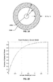
- FIG. 20 depicts a plot of the fraction of the light intensity that is emanated outside of an arbitrary inner radius r i that would fall within the bounds of an annular region with an inner radius r i and an annular width as indicated along the x-axis, in accordance with an example implementation.
- FIG. 21 depicts a light source, HAR photodetector, and various reference annotations.
- FIGS. 22 through 24 depict cross-sections of simplified representations of various PPG sensors, in accordance with various example implementations.
- FIG. 25 depicts an example of an annular photodetector element with a light source in the middle, in accordance with an example implementation.
- FIG. 26 depicts an example of a polygonal photodetector element with a light source in the middle, in accordance with an example implementation.
- FIG. 27 depicts a high-level block diagram of a PPG sensor, in accordance with an example implementation.
- the present disclosure relates to PPG sensors and, more particularly, to PPG sensors designed for use with wearable biometric monitoring devices (also referred to herein as “biometric tracking devices,” “biometric tracking modules,” “wearable fitness monitors,” or the like).
- biometric tracking devices also referred to herein as “biometric tracking devices,” “biometric tracking modules,” “wearable fitness monitors,” or the like.
- biometric tracking devices also referred to herein as “biometric tracking devices,” “biometric tracking modules,” “wearable fitness monitors,” or the like.
- biometric tracking devices also referred to herein as “biometric tracking devices,” “biometric tracking modules,” “wearable fitness monitors,” or the like.
- FIG. 2 depicts a simplified representation of a wristband-type wearable fitness monitor 200 that incorporates a PPG sensor that uses a non-square photodetector element in accordance with an example implementation of the concepts arrived at by the present inventors and discussed below.
- the wearable fitness monitor 200 shares many components in common with the prior art wearable fitness monitor 100 , including the control logic, the housing 104 and the straps 102 , the back face 128 , and the two light sources 108 .
- the wearable fitness monitor 200 features a photodetector element 212 which has a non-square active area in place of the photodetector element 112 .
- PPG sensors operate by shining light into a person's skin. This light diffuses through the person's flesh and a portion of this light is then emitted back out of the person's skin in close proximity to where the light was introduced into the flesh; the amount of light that is emitted back out of the person's flesh attenuates with increasing distance from the light source. This effect can be seen when one holds a bright penlight or other concentrated light source against one's skin; the flesh surrounding the area where the light source contacts the skin will glow red or orange from the diffused light. While imperceptible to the human eye, the amount of this light that is emanated from the person's skin will fluctuate in sync with the person's heart rate.
- the person's blood vessels expand and contract in synch with the heart as the pumping of the heart exerts pressure on the person's blood which, in turn, results in cyclic pressure increases in the person's blood vessels.
- a blood vessel expands, it allows more blood to flow into the vessel, which results in the amount of blood present in a given region of the person's flesh fluctuating in rhythm with the person's heart rate. This, in turn, results in fluctuations in the amount of light from the light source that is emanated back out of the flesh.
- the heart rate may then be determined by measuring the amount of light that emanates back out of the person's flesh via the above-described diffusion mechanism.
- Such measured light may have two components—a component that remains constant, i.e., the light that generally emanates from the skin regardless of heart rate, and a component that fluctuates with heart rate.
- the light that remains constant may be referred to herein as “DC,” as it may be thought of as analogous in some respects to direct current since it remains relative constant over time.
- the light that fluctuates may be referred to herein as “AC,” as it may be thought of as analogous to alternating current since it fluctuates relatively regularly over time.
- a typical heart rate might range from 50 beats per minute (BPM) to 200 bpm, and the AC component of light may have a frequency that maps to the heart rate frequency.
- AC optical power or, more generally, simply as “light intensity”
- light intensity may be much smaller in magnitude than the DC component, as a large amount of the light that is diffused into the person's skin and then emanated out will still emanate regardless of the changes in the amount of blood present due to the heart beating.
- the AC component is of principle interest since it is what is indicative of heart rate.
- FIG. 3 is a theoretical plot of emitted light intensity and detected light intensity for an example PPG sensor that is used to obtain heart rate information from a person's flesh, in accordance with an example implementation. It is to be understood that FIG. 3 is not to scale and does not depict actual data; it is merely intended to assist the reader in understanding the difference between the AC and DC components of a detected light signal.
- the horizontal axis indicates time, and the vertical axis indicates light intensity.
- light is emitted into the person's flesh at a constant value 350 in this example.
- Light emanating from the person's skin is then measured by a photodetector element; this measured light intensity is depicted as data trace 348 .
- the data trace 348 may be split into a DC component 346 , which does not fluctuate with time, and an AC component 344 , which does fluctuate with time.
- a conventional PPG sensor may include a square photodetector element that is located near a light source (or, in many cases, near two or more light sources).
- the present inventors determined that such an arrangement was inefficient in terms of signal collection as a function of potential power consumption.
- photodetectors are typically composed of a single photosensitive lateral area, e.g., the area of the photodetector that is parallel to the photodetector die top surface, that provides an output signal that indicates the total amount of light that is incident on the photosensitive cell at any given moment in time.
- the amount of power that such a photodetector consumes is directly tied to the size of the photosensitive area of the photodetector.
- the present inventors determined that, for a square photodetector element, a large percentage of the photodetector element may be located in positions where a much lower amount of AC light is emanated in comparison to locations where other portions of the photodetector element are located. This effect is discussed in more detail with respect to some of the Figures, as set forth below.
- FIG. 4 depicts a grey-scale plot of measured AC power intensity for light emanated from a rectangular region measuring approximately 4.5 mm wide by 5 mm tall on a person's arm near the wrist, in accordance with an example implementation.
- FIG. 4 was a 1.9 mm diameter green-wavelength LED, although the illumination beam that it produced was concentrated in an area smaller than that.
- FIG. 4 is based on actual image data taken with a human subject; as such, it includes various imperfections, such as hairs, that result in asymmetries in the light intensity detected.
- the light source that was used in this example emitted light that was predominantly in the 515 nm to 545 nm range, i.e., primarily green light.
- the rectangular region has been divided into twelve rectangular bins; the number in each bin indicates the fraction of the overall AC light intensity (also referred to as the “power fraction”) within the total bin area that is attributable to that particular bin.
- the bin in the lower left corner sees 20% of the total AC light intensity or power that is emitted from the totality of the twelve bins, whereas the bin immediately to the right of that bin only sees 9% of the total AC light intensity or power within that region.
- FIG. 4 also depicts the footprint 442 of a typical, square photodetector element at a spacing of approximately 2.5 mm from the light source center.
- the terms “photodetector element,” “active area,” “active region,” “photosensitive area,” and “footprint” (with respect to a photodetector) all refer to the same portion of a photodetector, namely, the area of the photodetector that can actually detect light that is incident on the photodetector. It is to be understood that photodetectors may also include other components that are outside of the active area, such as interconnects, circuits, application-specific integrated circuits (ASICs), etc. that interact with the photodetector element in order to provide power or produce signal output.
- ASICs application-specific integrated circuits
- a photodetector with a 2 mm by 2 mm square photodetector element having a 1 mm by 2 mm ASIC located adjacent to one edge of the photodetector element might have an overall size of 3 mm by 2 mm, which would be rectangular, but the photodetector element of that photodetector would not be rectangular since the ASIC is not part of the photodetector element.
- reference herein to a “square” photodetector refers to a photodetector that has a square photodetector element, regardless of the aspect ratio that the entire photodetector has.
- rectangular or non-square photodetector is to be understood as referring to a photodetector with a rectangular or non-square, respectively, photodetector element, regardless of whether the photodetector overall has a square shape.
- the square photodetector element Due to the aspect ratio and positioning of the square photodetector element, more than half of the active area is only able to measure light from the rightmost six bins, which represent only 14% of the available AC power in the overall bin area.
- the square photodetector element will not even collect all of the available light from those rightmost six bins since it only fully overlaps one of those rightmost six bins—only part of the light emanated from the remaining five bins of the rightmost six bins will be collectable by the square photodetector element. As shown, the square photodetector element may only be able to measure about 20% of the available light intensity that is emitted across all twelve bins.
- the square photodetector element may collect roughly 50% of the AC optical power available in the 12 bins.
- the present inventors have determined that a significant performance increase may be realized by deviating from the typical square (or nearly-square) aspect ratios that are used in photodetector elements of conventional PPG sensors. More specifically, the present inventors have determined that using a high-aspect-ratio photodetector element may provide a significant improvement in the amount of AC light measurable by a photodetector without incurring a significant power consumption penalty as compared with square photodetectors of the same active area.
- the term “high-aspect-ratio” (or “HAR”) photodetector refers to non-square photodetectors where at least 90% of the photodetector element active area, which may be referred to herein as the “active area of interest,” has a maximum first dimension along a first axis that is at least twice as large as a maximum second dimension of the photodetector element along a second axis that is perpendicular or orthogonal to the first axis; the second axis is parallel to a ray emanating from the center of a light source used with the photodetector to form a PPG sensor, and the first axis is perpendicular to that ray.
- the maximum first dimension may be thought of as the distance between two lines that are both parallel to the ray emanating from the center of the light source and that pass through the opposing ends of the active area of interest that are furthest from the ray in directions perpendicular to the ray.
- the maximum second dimension correspondingly, may be thought of as the distance between two lines that are both perpendicular to the ray emanating from the center of the light source and that pass through the opposing ends of the active area of interest that are furthest from and closest to the center of the light source.
- the “maximum first dimension” may also be referred to herein and in the claims as the “height” or “length” of a HAR photodetector, and the “maximum second dimension” may also be referred to herein and in the claims as the “base” or “width” of a HAR photodetector.
- FIG. 5 depicts the same light intensity image map of FIG. 4 , but with the outline of a high-aspect-ratio photodetector element added to the Figure, in accordance with an example implementation.
- the HAR photodetector element outline that is shown has a height-to-width aspect ratio of approximately 2.8 to 1, and completely overlaps with the leftmost six bins, which represent nearly 85% of the available AC power in the overall bin area.
- the HAR photodetector element shown in FIG. 5 is able to collect nearly four times as much light as the square photodetector element shown in FIG. 4 .
- the HAR photodetector is able to offer such improved light collection capabilities while still having substantially the same active area as the square photodetector of FIG. 4 .
- a square photodetector element may have an active area of approximately 7 mm 2 and a HAR photodetector element may have an active area of approximately 7 mm 2 .
- the power consumed by both the square photodetector and the HAR photodetector will be approximately equal since they have the same active area.
- the HAR photodetector in the example simulation shown in FIG. 5 offers a 300% improvement in collected AC power as compared with a traditional square photodetector implementation as set forth in FIG. 4 , while requiring effectively no additional power in order to attain such an improvement.
- FIG. 6 depicts a simulation of the AC intensity or power of light that is emanated within a 16 mm by 16 mm region of skin as a result of light that is shined into the skin at the center of the region, in accordance with an example implementation.
- the HAR photodetector footprint 654 overlaps with higher-density stippling/light intensity regions than is the case with the square photodetector footprint 652 .
- FIG. 7 depicts a plot of measurable AC light power as a function of photodetector footprint aspect ratio with regard to the simulation shown in FIG. 6 , in accordance with an example implementation.
- the vertical axis represents the AC light power that is measurable by the photodetector
- the horizontal axis represents the aspect ratio of the photodetector; the vertical axis has been normalized such that a 1:1 aspect ratio photodetector provides a measurable AC light power value of 1.
- a HAR photodetector such as a photodetector with an aspect ratio of 2:1 or 3:1
- the amount of AC light that is measurable by the HAR photodetector may be increased by up to 20% as compared with the square photodetector.
- a HAR photodetector with an aspect ratio of between 3:1 and 4:1 provides the highest performance in this respect.
- the term “between,” with reference to a range is used to indicate a range that is inclusive of the upper and lower limits of the range.
- aspect ratios of 3:1 and 4:1 would be included in the range of “between 3:1 and 4:1.”
- This convention is used throughout this paper and in the claims. The same observation may be made with respect to the use of “to” to describe an implied range, e.g., “a ratio of 3:1 to 4:1” would mean “between 3:1 to 4:1” and 3:1 and 4:1 would be included in this range.
- FIG. 8 depicts a plot of measurable AC light power as a function of photodetector footprint aspect ratio with regard to the simulation shown in FIG. 6 , but with the edge of the photodetector closest to the center of the light source offset from the light source center by 2.6 mm instead of 1.65 mm, in accordance with an example implementation.
- the vertical axis represents the AC light power that is measurable by the photodetector, and the horizontal axis represents the aspect ratio of the photodetector; the vertical axis has been normalized such that a 1:1 aspect ratio photodetector provides a measurable AC light power value of 1.
- a PPG sensor may utilize one or more HAR photodetector elements having aspect ratios of between 2:1 and 5:1.
- a PPG sensor may utilize one or more HAR photodetector elements having ratios of between 2:1 and 7:2, and in some other implementations, a PPG sensor may utilize one or more HAR photodetector elements having ratios of between 7:2 to 5:1.
- HAR photodetector elements may have proportions that fall substantially between the aspect ratios discussed herein, both prior to and after this point, e.g., HAR photodetector elements may also have dimensions within ⁇ 0.1 mm of dimensions that would satisfy such aspect ratios or have aspect ratios within ⁇ 10% of such aspect ratios, e.g., for a 2:1 to 5:1 aspect ratio range, HAR photodetector elements having aspect ratios of 1.8:1 or 5.5:1 may be considered as having aspect ratios substantially between aspect ratios between 2:1 and 5:1.
- HAR photodetectors may have increased effectiveness when arranged and sized according to one or more guiding principles, as discussed in more detail below.
- At least 90% of the active or photosensitive area of a HAR photodetector may have a maximum first dimension along a first axis that is at least twice as large as a maximum second dimension of the active or photosensitive area along a second axis that is perpendicular or orthogonal to the first axis; the second axis is parallel to a ray emanating from the center of a light source used with the photodetector to form a PPG sensor, and the first axis is perpendicular to that ray.
- FIG. 9 depicts a diagram of a HAR photodetector element 912 that is rectilinear, in accordance with an example implementation.
- the active area of the HAR photodetector element 912 is rectangular and has a first dimension 986 along an axis that is perpendicular to a ray 956 emanating from the center of a light source 908 , and a second dimension 988 along an axis that is parallel to the ray 956 ; the first dimension 986 and the second dimension 988 are thus orthogonal to one another.
- the HAR photodetector element 912 in this case, has a form factor where the active area as a whole has a first dimension 986 that is three times larger than the second dimension 988 , i.e., 100% of the active or photosensitive area of the HAR photodetector element 912 has a maximum first dimension that is at least twice (in this case, thrice) as large as the maximum second dimension.
- the HAR photodetector element 912 is a rectangular element, which is the most efficient shape in terms of manufacturing yield, as such photodetector elements may be made by simply dicing a semiconductor wafer with the requisite semiconductor elements for the photodetector elements in a rectangular grid, much in the same manner that square photodetector elements are manufactured (just with a different dicing spacing).
- HAR photodetectors may also take on HAR shapes other than simple rectangles. Several examples of such alternative photodetector elements are discussed in more detail below.
- FIG. 10 depicts a diagram of a HAR photodetector element 1012 that is generally rectangular, but that possesses some non-rectangular aspects, in accordance with an example implementation.
- the HAR photodetector element 1012 may have a first edge that is closest to the light source 1008 , and an arcuate second edge that is opposite the first edge. If one considers the entire active area of the HAR photodetector element 1012 , it is apparent that the HAR photodetector element 1012 has an active area with a maximum first dimension 1090 and a maximum second dimension 1092 , which is the same as with the HAR photodetector element 912 . Thus, the depicted HAR photodetector element 1012 would also be considered to have an aspect ratio of 3:1.
- FIG. 11 depicts a diagram of a HAR photodetector element 1112 that is similar to the HAR photodetector element of FIG. 10 , but with a rectangular cutout along the first edge, in accordance with an example implementation. While the active area of such a photodetector element differs from the photodetector elements of FIGS. 9 and 10 , the HAR photodetector element 1112 active area still has a maximum first dimension 1190 that is three times larger than a maximum second dimension 1192 of the active area.
- FIG. 12 depicts a diagram of a HAR photodetector element 1212 that is similar to the HAR photodetector element of FIG. 9 , but one where the active area is generally rectangular yet has a “peninsula” that protrudes out from the rectangular area, in accordance with an example implementation.
- the maximum first dimension 1290 and the maximum second dimension 1292 ′ would technically be the same, which would result in an aspect ratio of 1:1.
- the active area of the peninsula is omitted, the remaining 90% of the active area of the photodetector element 1212 , e.g., active area of interest 1294 , indicated by diagonal cross-hatching, has a maximum first dimension 1290 that is three times larger than the maximum second dimension 1292 . Accordingly, such a photodetector element 1212 may be considered to be a HAR photodetector element under the conditions described herein.
- FIG. 13 depicts a diagram of a HAR photodetector element 1312 that is arcuate in shape, in accordance with an example implementation.
- the HAR photodetector element 1312 has an active area with a maximum first dimension that is also three times larger than the maximum second dimension.
- photodetector elements shown in FIGS. 9 through 13 may be classified as HAR photodetector elements since at least 90% of the active or photosensitive area of each of these photodetector elements has a maximum first dimension along a first axis, where the first axis is perpendicular to a ray emanating from the center of the light source of a PPG sensor, that is at least twice as large as a maximum second dimension of the active or photosensitive area along a second axis that is perpendicular or orthogonal to the first axis.
- photodetector elements that may be considered to be HAR photodetector elements, commensurate with the above discussion.
- multiple light-emitting devices may, for example, be spaced apart from one another, as shown in FIGS. 1 and 2 , or may be closely grouped. In some implementations, all such light sources may be the same type of light source. In some other implementations, however, different types of light sources may be used for some or all of the light sources. For example, it may be desirable to utilize an LED that predominantly emits light in the green light spectrum for the purposes of detecting heart rate since the fluctuations in the light that is emitted back out of the person's skin may be more pronounced in the green light spectrum. At the same time, photoplethysmographic techniques may also be used to measure other physiological parameters besides heart rate, such as blood oxygenation levels.
- each light-emitting device may be used to supply light for a different type of photoplethysmographic measurement.
- these light-emitting devices or light sources may be distributed across the PPG sensor face—for example, the light source 108 on the left side of FIG. 2 may be a green-wavelength LED, and the light source 108 on the right side of FIG. 2 may be a red- or infrared-wavelength LED.
- light emitting devices may be closely clustered together, e.g., within a millimeter or two or less of each other; in such implementations, the clustered light-emitting devices may be viewed as a single light source with a center point that is, for example, associated with the centroid of the light intensity distribution of the cluster of light-emitting devices when all of the light-emitting devices in the cluster are emitting light simultaneously or that is associated with the averaged location of all of the light-emitting devices in the cluster.
- the center of the light source is to be understood as corresponding to a point generally associated with the centroid of the light intensity distribution of that light-emitting device, e.g., typically the center of the LED.
- the term “light-emitting device,” as used herein refers to a single, discrete light-emitting device, such as a single LED or a laser diode
- the term “light source,” as used herein refers to one or more light-emitting devices that are generally treated as a unit, e.g., that are close enough together that an observer would not be able to discern a gap between the light-emitting devices in a group of light-emitting devices when the light-emitting devices in the group are all emitting light simultaneously and the observer is approximately two to three feet from the light-emitting devices (this assumes that the light-emitting devices are emitting light in a spectrum visible to the observer; for light-
- Conventional PPG sensors featuring square photodetector elements may utilize two light sources that bracket the photodetector element so that the fall-off in illumination intensity that is evident in FIG. 4 may be mitigated—in such an arrangement, the light intensity along the left edge of the depicted area of FIG. 4 may be mirrored along the right edge of the depicted area, resulting in a valley of lower-intensity light near the middle of the square photodetector, but with both the left and right edges of the square photodetector seeing increased light intensity. This, however, requires that two LEDs be powered, instead of one, effectively doubling the power consumption attributable to the light sources.
- the present inventors have determined that utilizing a HAR photodetector element, in some cases, can present a much more power-efficient technique for achieving increased sensor performance than the conventional approach of including multiple light sources, as a HAR photodetector element and single light source may achieve performance that is comparable or superior to the performance of a square photodetector with multiple light sources—thus avoiding the use of the extra light source (and avoiding the extra power consumption it would incur).
- the present inventors have also determined that further increases in PPG sensor performance may be attained, in some cases, by arranging multiple HAR photodetectors in an array or pattern about a light source. Since the same light source may provide light to multiple HAR photodetectors, there is little or no additional power consumption attributable to the light source in such implementations as compared with implementations having only one photodetector element.
- the use of such HAR photodetector elements may also increase the signal to ambient noise ratio of the PPG sensor.
- FIGS. 14 through 16 depict several examples of implementations with multiple HAR photodetectors, in accordance with several example implementations.
- two HAR photodetector elements 1412 are shown with a light source 1408 interposed midway between them.
- three HAR photodetector elements 1512 are shown in a circular array centered on a light source 1508 .
- four HAR photodetector elements 1612 are arranged in a circular array about a light source 1608 . It is not necessary for the HAR photodetector elements in such patterns or arrays to be equidistantly-spaced, as is shown in the implementations of FIGS. 14, 15, and 16 .
- a three-element array may be formed by removing one of the photodetector elements 1612 from the array shown in FIG. 16 . It is also not necessary for the photodetector elements within such a pattern or array to all be the same size and shape.
- the upper and lower photodetector elements 1612 in FIG. 16 might have aspect ratios of 5:1, and the left and right HAR photodetector elements 1612 in FIG. 16 might have aspect ratios of 3:1 (which is the actual aspect ratio depicted).
- FIG. 17 depicts another example arrangement of photodetector elements. In FIG.
- the upper and lower HAR photodetector elements 1612 may have aspect ratios of 2:1, and the left and right HAR photodetector elements 1612 may have aspect ratios of 3:1; in some such implementations, the shorter photodetector elements, e.g., the 2:1 aspect ratio photodetector elements 1712 in the depicted example, may be positioned with the midpoints of their shorter edges generally located along a line spanning between the short edges of the longer photodetector elements, e.g., the 3:1 aspect ratio photodetector elements 1712 in the depicted example. In some PPG implementations involving multiple HAR photodetector elements, the HAR photodetector elements may occupy more than 50% of an annular region about the light source that has an annular width of 1 mm.
- FIG. 18 depicts an example of a PPG sensor photodetector layout as shown in FIG. 15 but with multiple light-emitting devices used in the light source, in accordance with an example implementation.
- a PPG sensor may utilize one or more light sources, each of which may include one or more light-emitting devices.
- the light source 1808 includes two light-emitting devices 1810 , which may, for example, be surface-mount LEDs, one emitting primarily green-wavelength light and the other emitting primarily red-wavelength light.
- the two light-emitting devices 1810 may define a center point 1866 located midway between them, and may, in combination, be viewed as forming a light source 1808 .
- the light-emitting devices 1810 may be operated independently and may not be powered on simultaneously during actual use.
- the array of photodetector elements 1812 may not appear to be centered on the center of either light-emitting device 1810 when that light-emitting device 1810 is on, but the array of photodetector elements 1812 may, nonetheless, be considered to be centered on the light source 1808 .
- HAR photodetector elements in at least some implementations, may be sized such that their width or the second maximum dimension of at least 90% of the active area of the HAR photodetector element is between approximately 0.5 mm and 1 mm; there may be some deviation from this range in some of these implementations, such as HAR photodetector elements where this dimension ranges between 0.45 mm and 1.1 mm.
- the light intensity for light emanating from a person's skin from a PPG light source falls off in an axially symmetric manner with increasing distance from the center of the light source (this assumes a single light source PPG sensor). Accordingly, the light source may be surrounded by a plurality of concentric, annular regions that each correspond with a different average light intensity.
- the present inventors analyzed the characteristics of such annular regions and determined that, regardless of the inner radius of a particular annular region, approximately 80% of the available power or intensity of the emanated light available outside of the inner radius of the annular region occurs within 1 mm of the inner radius.
- any particular annular region with an annular width of approximately 1 mm will see approximately 80% of the light intensity/power that is available outside of the inner radius of that annular region.
- the “annular width” (w) of an annular region is equal to the outer radius (r o ) of the annular region minus the inner radius (r i ) of the annular region.
- FIG. 19 shows a light source 1908 and a surrounding annular region 1958 , in accordance with an example implementation; the inner radius r i , the outer radius r o , and the annular width of the annular region 1958 are indicated.
- FIG. 20 depicts a plot of the fraction of the light intensity that is emanated outside of an arbitrary inner radius r i that would fall within the bounds of an annular region with an inner radius r i and an annular width as indicated along the x-axis, in accordance with an example implementation. As can be seen, approximately 80% of the available light intensity falls outside the inner radius r i and within 1 mm of the inner radius r i .
- the present inventors determined that, given the high concentration of emanated light intensity within this 1 mm zone, sizing HAR photodetectors so as to have approximately a 1 mm width or less or such that the second dimension referenced above is approximately 1 mm or less may, in some implementations, offer enhanced performance in a PPG sensor.
- HAR photodetector elements may be sized and arranged to satisfy certain geometric constraints.
- the size of the HAR photodetector element may be constrained by certain geometric relationships, as described further below with respect to FIG. 21 .
- FIG. 21 depicts a light source, HAR photodetector, and various reference annotations.
- a HAR photodetector element 2112 is shown positioned at a distance r i from a light source 2108 .
- An annular region 2158 having an inner radius of r i and an outer radius of r o may be centered on the light source 2108 .
- the difference between r i and r o for the annular region 2158 in such implementations may be less than or equal to 2 mm.
- the HAR photodetector element 2112 may subtend an angle ⁇ at the light source center, as shown.
- the HAR photodetector may be sized such that a) there is at least 80% overlap between the annular region 2158 and the HAR photodetector element 2112 (the overlap is indicated in FIG. 21 by diagonal cross-hatching; approximately 86% of the HAR photodetector 2112 in this example overlaps with the annular region 2158 ) and b) the angle ⁇ is at least:
- the HAR photodetector 2112 may be further sized such that the angle ⁇ is not more than:
- FIGS. 22 through 24 depict cross-sections of simplified representations of various PPG sensors, in accordance with various example implementations. Similar components in each of FIGS. 22 through 24 are indicated by numeric indicators having the last two digits in common, and may only be described once with respect to FIG. 22 ; this description is also applicable, however, to the corresponding elements in FIGS. 23 and 24 .
- a substrate 2272 supports two HAR photodetector elements 2212 that are positioned on either side of a light source 2208 .
- a window 2278 is offset from the substrate 2272 .
- the window 2278 in this implementation, is made from a translucent or transparent material, such as transparent acrylic, with an in-mold label 2276 embedded within it.
- the in-mold label 2276 may be black or otherwise rendered opaque to light to prevent light from entering or exiting the PPG sensor through the window 2278 except through window regions 2226 .
- other masking techniques such as a painted or silk-screened mask applied to the window 2278 , may be used.
- the in-mold label 2276 or the masking may prevent stray light from other sources, e.g., ambient light, from reaching the HAR photodetector elements 2212 and affecting the heart rate signal obtained by the PPG sensor.
- the window 2278 may be held against a person's skin, e.g., by being held in place with a strap, when heart rate measurements are obtained to allow light from the light source 2208 to shine through its associated window region 2226 and into the person's skin, where the light then diffuses into the surrounding flesh and is then emitted back out of the person's skin and into the HAR photodetector elements 2212 through the respective window regions 2226 associated with the HAR photodetector elements 2212 .
- the light source 2208 may be separated from the HAR photodetector elements 2212 within the PPG sensor by walls 2274 , which may extend to the window 2278 or may stop short of the window 2278 .
- an adhesive gap filler e.g., black silicone, may be used to bridge any gap remaining between the walls 2274 and the window 2278 .
- a gap 2280 may exist between the window 2278 and the HAR photodetector elements 2212 in some implementations, although in other implementations, this gap may be eliminated and the HAR photodetector element 2212 may be butted up against the window 2278 .
- the walls 2274 may prevent light from the light source 2208 from reaching the HAR photodetector elements 2212 by following paths completely within the housing of the PPG sensor. As can be seen, the window regions 2226 through which the light reaches the HAR photodetector elements 2212 each overlap their respective HAR photodetector elements 2212 .
- the window regions 2226 are mutually coextensive with their respective HAR photodetector elements 2212 , although in other implementations, the window regions 2226 may be smaller or larger than their respective HAR photodetector elements 2212 , e.g., to accommodate assembly tolerance mismatch.
- FIG. 23 depicts a PPG sensor implementation that is similar to the PPG sensor of FIG. 22 except that the window 2378 does not include any masking, for example, in the form of an in-mold label, such as in-mold label 2276 .
- the walls 2374 also extend closer to the window 2378 .
- the window 2378 is optically transparent across the entire depicted span.
- FIG. 24 depicts a PPG sensor implementation that is similar to the PPG sensor implementation of FIGS. 22 and 23 , except that the contiguous windows 2278 and 2328 have been replaced with discrete windows 2478 .
- each window 2478 may have its own window region 2426 that overlaps with a different one of the light source 2408 or the HAR photodetector elements 2412 .
- the windows 2478 may be glued or otherwise held in place within a frame that may supply the walls 2474 .
- the windows 2478 may be formed by filling the recesses formed by the walls 2474 and other surrounding structure with a clear, flowable material, such as epoxy, and then allowing the flowable material to cure and harden.
- the gap 2480 may not exist since the flowable material may encapsulate the HAR photodetector elements 2412 .
- the window regions 2226 , 2326 , or 2426 overlap with the HAR photodetector elements such that light that enters the PPG sensor via the window regions generally takes a direct route to the HAR photodetector element, as compared with a route that involves forcing the light to travel in a direction parallel to the window, as may be done with various types of optical light guides.
- optical light guide refers to particular types of optical structures that redirect or transport the light that enters through a surface within a first region of the surface such that a majority of that light is transported in a direction generally transverse to the surface to an area overlapped by a second region of the surface that is offset from the first region along the surface.
- Optical light guides are not to be confused with other optical structures, such as microlens arrays or lenses that may be placed over a HAR photodetector element to improve collection efficiency, optical windows that may slightly refract light that passes through the windows but that do not transport or redirect light in a significant manner in directions transverse to the surface, optical filters that may simply filter light of certain wavelengths, etc.
- optical light guides there is no need for optical light guides since the HAR photodetector elements are generally overlapped by the window regions.
- the above concepts have been discussed primarily with respect to light sources that emit green light, e.g., wavelengths in the range of 500 nm to 550 nm, although it is contemplated that the photodetector element concepts discussed herein may see similar performance with light sources that emit light predominantly in the 500 nm to 600 nm range, which includes yellow light as well as some light orange light.
- Light sources emitting light in the green spectrum are particularly well-suited for photoplethysmographic techniques for measuring heart rate.
- other photoplethysmographic techniques such as techniques for measuring blood oxygenation levels, may be most effective using light of dramatically different wavelengths, such as in the red wavelengths, e.g., 660 nm, or in the infrared spectrum.
- the aspect ratios and dimensional values discussed herein are tailored based on the green/yellow light spectrum and are not tailored for use in other spectrums, such as the red or infrared spectra.
- the light source(s) and photodetector element(s) of such implementations may be arranged such that the photodetector element(s) are positioned with the edge closest to the light source located between 1 mm to 4 mm from the center or edge of the light source.
- implementations discussed herein may be used in products that achieve closer or farther spacing from the light source center, such as spacing closer than 1 mm or farther than 4 mm.
- the HAR photodetector elements that may be used in a PPG may be positioned with the edge closest to the light source of the PPG sensor offset from the center of the light source by between 1 mm and 4 mm and may be sized such that they have a maximum first dimension substantially between 1 mm and 5 mm and a maximum second dimension substantially between 0.05 mm and 2 mm, while being consistent with the aspect ratio of the maximum first dimension to the maximum second dimension being substantially between 2:1 to 5:1.
- the photodetector element may be positioned with its closest edge further than 4 mm from the center of the light source, doing so may prove counterproductive, as a higher-intensity light source may be needed to ensure that sufficient light is diffused across the increased distance in order to obtain a sufficiently strong signal at the photodetector. As a higher-intensity light source will generally consume additional power, such a compromise may be undesirable in a wearable fitness monitor context.
- performance increases over square-photodetector-based PPGs for heart rate measurement may be realized through the use of non-HAR and non-square photodetector elements that generally encircle the light source and that have a central opening in the middle for the light source to shine through.
- photodetector elements may have an exterior periphery that is defined by a first boundary, and a second boundary, within the first boundary, that defines the central opening.
- FIGS. 25 and 26 depict two example implementations of such PPG sensors.
- FIG. 25 depicts an example of an annular photodetector element 2512 with a light source 2508 in the middle, in accordance with an example implementation.
- the annular photodetector element 2512 may have an exterior periphery defined by a first boundary 2532 and a central opening defined by a second boundary 2534 ; the first boundary 2532 and the second boundary 2534 may be offset from one another by a first distance 2584 along a radius of the annular area.
- the light source 2508 may be a green wavelength light source that predominantly emits light between 500 nm and 550 nm or between 500 nm and 600 nm in wavelength.
- Such a photodetector element 2512 may be sized such that the ratio of the circumference of the second boundary 2534 to the first distance 2584 is between 9.5:1 and 11.5:1.
- the annular photodetector element 2512 may be sized such that the first boundary has a diameter of between 3 mm to 5.5 mm and the second boundary has a diameter of between 1 mm to 2.5 mm.
- FIG. 26 depicts an example of a polygonal photodetector element 2612 with a light source 2608 in the middle, in accordance with an example implementation.
- the polygonal photodetector element 2612 may have an exterior periphery defined by a first boundary 2632 and a central opening defined by a second boundary 2634 .
- the first boundary 2632 and the second boundary 2634 are both polygonal in nature, e.g., a six-sided polygon.
- first boundary 2632 and the second boundary 2634 may be offset from one another by a first distance 2684 along an axis perpendicular to the edges.
- first distance 2684 along an axis perpendicular to the edges.
- each side of the polygon forming the second boundary 2634 may have a second length 2682 , and the ratio of the second length 2682 to the first distance 2684 may be between 2:1 to 5:1.
- control logic refers to hardware and/or software that may be used to provide certain functionality, such as controlling when the light source(s) of a PPG is on or off, controlling the intensity with which the light source(s) is illuminated, collecting data from one or more photodetectors, and analyzing at least the data collected from the one or more photodetectors in order to determine a measurement of a person's heart rate.
- Control logic may include, for example, one or more processors and a memory that stores computer-executable instructions for controlling the one or more processors to provide such functionality.
- the control logic may also include various circuit elements that may provide aspects of such functionality without need for computer-executable instructions stored in memory.
- the control logic may be provided, at least in part, by an application-specific integrated circuit (ASIC).
- ASIC application-specific integrated circuit
- FIG. 27 depicts a high-level block diagram of a PPG sensor, in accordance with an example implementation.
- control logic 2706 is shown, which includes a processor 2768 and a memory 2770 , which are operatively coupled with one another.
- the control logic is operatively coupled with a light source 2708 and a photodetector element 2712 .
- the control logic 2706 may thus cause the light source 2708 to emit light at desired times, and may receive a signal indicative of an amount of detected light from the photodetector element 2712 .
- any of the implementations discussed above with respect to a single photodetector element spaced apart from a light source may also be implemented using a plurality of photodetector elements arranged about the light source, as discussed with respect to various other implementations discussed herein.
- the present invention is neither limited to any single aspect nor implementation, nor to any combinations and/or permutations of such aspects and/or implementations. Moreover, each of the aspects of the present invention, and/or implementations thereof, may be employed alone or in combination with one or more of the other aspects and/or implementations thereof. For the sake of brevity, many of those permutations and combinations will not be discussed and/or illustrated separately herein.
Abstract
Blood oxygenation sensors including high-aspect-ratio photodetector elements are discussed herein. Such high-aspect-ratio photodetector elements may provide improved signal-strength-to-power-consumption performance for blood oxygenation sensors incorporating such photodetector elements as compared with blood oxygenation sensors incorporating, for example, square photodetector elements.
Description
This application is a continuation of, and claims priority to, U.S. patent application Ser. No. 14/724,750, filed May 28, 2015, titled “HEART RATE SENSOR WITH HIGH-ASPECT-RATIO PHOTODETECTOR ELEMENT,” which is hereby incorporated herein by reference in its entirety.
Heart rate may be measured using any of a variety of different sensors, including, for example, electrode-based sensors, such as EKG sensors, and optical sensors, such as photoplethysmographic (PPG) sensors. PPG sensors typically include a light source and a photodetector that are placed adjacent to a person's skin. The light source and photodetector are typically arranged so that light from the light source cannot reach the photodetector directly. However, when the PPG sensor is placed adjacent to a person's skin, light from the light source may diffuse into the person's flesh and then be emitted back out of the person's flesh such that the photodetector can detect it. The amount of such light that is emitted from the person's flesh may vary as a function of heart rate, since the amount of blood present in the flesh varies as a function of heart rate and the amount of light that is emitted from the person's flesh, in turn, varies as a function of the amount of blood present.
The assignee of this application, Fitbit, Inc., makes wearable fitness monitoring devices, some of which, such as the Charge HR™ and the Surge™, incorporate PPG sensors that include two high-brightness, green light-emitting diodes (LEDs) that are spaced approximately 8 mm apart, as well as a 2 mm square photodetector element located midway between the LEDs. Various other companies that make wearable fitness monitoring devices utilize a similar architecture. For example, the Basis Peak™ incorporates two green LEDs with a square photodetector element located midway between them, as does the Motorola Moto 360™.
Details of one or more implementations of the subject matter described in this specification are set forth in the accompanying drawings and the description below. Other features, aspects, and advantages will become apparent from the description, the drawings, and the claims. Note that the relative dimensions of the following figures may not be drawn to scale unless specifically indicated as being scaled drawings.
In some implementations, an apparatus having a light source and one or more discrete photodetector elements may be provided. Each photodetector element may have a first edge having a first length and may also have a first width in a direction perpendicular to the first edge. The apparatus may also include control logic, which may be communicatively connected with the light source and each photodetector element and configured to cause the light source to emit light, obtain one or more measured light intensity measurements from the one or more photodetector elements, and determine a heart rate measurement based, at least in part, on the one or more light intensity measurements. In such implementations, the ratio of the first length to the first width of each photodetector may be substantially between 2:1 to 5:1.
In some such implementations, the first edge of each photodetector element may be perpendicular or transverse to an axis radiating out from a center of the light source.
In some implementations of the apparatus, the light source may include a plurality of light-emitting devices.
In some such implementations, the plurality of light-emitting devices may include at least two light-emitting devices that predominantly emit light of different wavelengths. In some further or alternative such implementations, there may be a plurality of photodetector elements arranged in a pattern, and the plurality of light-emitting devices may be collocated at a center point of the pattern of photodetector elements. In some such implementations, each photodetector element in the pattern may be equidistant from the center of the light source and/or evenly spaced within the pattern.
In some implementations of the apparatus, the ratio of the first length to the first width of each photodetector element may be substantially between 2:1 to 3.5:1. In some other implementations of the apparatus, the ratio of the first length to the first width of each photodetector element may be substantially between 3.5:1 to 5:1.
In some implementations of the apparatus, each photodetector element may have a first length between 1 mm and 5 mm and a first width between 0.5 mm and 2 mm, with the ratio of the first length to the first width substantially between 2:1 to 5:1, and each such photodetector element may be positioned such that an edge of the photodetector element closest to the light source is between 1 mm and 4 mm from the light source.
In some implementations of the apparatus, there may be a pattern of photodetector elements that includes three or four photodetector elements that are equidistantly spaced about the light source.
In some implementations of the apparatus, the apparatus may also include a housing having a back face that includes one or more transparent window regions through which light may enter the apparatus. In such implementations, each photodetector element is positioned such that that photodetector element is overlapped by a corresponding one of the one or more transparent window regions, and the housing may be configured such that the back face is adjacent to the skin of a person wearing the apparatus when the apparatus is worn by that person.
In some such implementations of the apparatus, the back face may include a thin window, and the window regions may be sub-regions of the window that are defined by the photodetector elements. In some other or additional such implementations, each photodetector element may be offset from the corresponding transparent window region by a corresponding gap in a direction normal to the photodetector element, and the gap may be free of optical light guides.
In some implementations of the apparatus, each photodetector element may, in addition to the first edge, have an arcuate second edge opposite the first edge. The arcuate second edge may have a maximum distance from the first edge, when measured along a direction perpendicular to the first edge, that is equal to the first width.
In some implementations, an apparatus may be provided that includes a first light source and a second light source, as well as a photodetector element interposed between the first light source and the second light source. The apparatus may also include control logic that is communicatively connected with the first and second light sources and the photodetector element and that is configured to cause the first light source and the second light source to emit light, obtain measured light intensity measurements from the photodetector element, and determine a heart rate measurement based, at least in part, on the light intensity measurements. In such implementations, the photodetector element may be rectangular in shape, have a first edge with a first length, and have a second edge, perpendicular to the first edge, with a second length. Furthermore, in such implementations, the ratio of the first length to the second length may be substantially between 2:1 to 5:1.
In some such implementations, the first edge of each photodetector element may be perpendicular or transverse to an axis spanning between a center of the first light source and a center of the second light source.
In some other or additional such implementations, the apparatus may include a housing having a back face that includes a transparent window region that overlaps the photodetector element and two further window regions that are each associated with a different one of the first light source and the second light source and that allow light from the associated light source to pass through the back face. In such implementations, the first light source and the second light source may be the only light sources in the apparatus configured to emit light through the back face, and the housing may be configured such that the back face is adjacent to the skin of a person wearing the apparatus when the apparatus is worn by that person.
In some implementations of the apparatus, the photodetector element may be equidistant from the first light source and the second light source.
In some implementations, an apparatus may be provided that includes a light source and one or more photodetectors, each photodetector having a photosensitive area. In such implementations, at least 90% of the photosensitive area of the photodetector is defined by a first dimension along a first axis and a second dimension along a second axis perpendicular to the first axis. The apparatus may also, in such implementations, include control logic that is communicatively connected with the light source and each photodetector and that is configured to cause the light source to emit light, obtain one or more measured light intensity measurements from the one or more photodetectors, and determine a heart rate measurement based, at least in part, on the one or more light intensity measurements. In such implementations, the ratio of the first dimension to the second dimension may be substantially between 2:1 to 5:1.
In some implementations of the apparatus, the light source may include a plurality of light-emitting devices. In some such implementations, the plurality of light-emitting devices may include at least two light-emitting devices that predominantly emit light of different wavelengths. In some further or alternative such implementations, there may be a plurality of photodetector elements arranged in a pattern, and the plurality of light-emitting devices may be collocated at a center point of the pattern of photodetector elements. In some such implementations, each photodetector element in the pattern may be equidistant from the center of the light source and/or evenly spaced within the pattern.
In some implementations of the apparatus, the ratio of the first length to the first width of each photodetector element may be substantially between 2:1 to 3.5:1. In some other implementations of the apparatus, the ratio of the first length to the first width of each photodetector element may be substantially between 3.5:1 to 5:1.
In some implementations of the apparatus, each photodetector element may have a first length between 1 mm and 5 mm and a first width between 0.5 mm and 2 mm, with the ratio of the first length to the first width substantially between 2:1 to 5:1, and each such photodetector element may be positioned such that an edge of the photodetector element closest to the light source is between 1 mm and 4 mm from the light source.
In some implementations of the apparatus, there may be a pattern of photodetector elements that includes three or four photodetector elements that are equidistantly spaced about the light source.
In some implementations of the apparatus, the apparatus may also include a housing having a back face that includes one or more transparent window regions through which light may enter the apparatus. In such implementations, each photodetector element is positioned such that that photodetector element is overlapped by a corresponding one of the one or more transparent window regions, and the housing may be configured such that the back face is adjacent to the skin of a person wearing the apparatus when the apparatus is worn by that person.
In some such implementations of the apparatus, the back face may include a thin window, and the window regions may be sub-regions of the window that are defined by the photodetector elements. In some other or additional such implementations, each photodetector element may be offset from the corresponding transparent window region by a corresponding gap in a direction normal to the photodetector element, and the gap may be free of optical light guides.
In some implementations, an apparatus may be provided that includes a light source and at least one photodetector element. The apparatus may also include control logic that is communicatively connected with the light source and the photodetector element and that is configured to cause the light source to emit light, obtain at least one measured light intensity measurement from the at least one photodetector element, and determine a heart rate measurement based, at least in part, on the at least one light intensity measurement. In such implementations, the at least one photodetector element may subtend an angle at the center of the light source of substantially at least: 2·arctan
radians, where ri is a measurement of a distance from the center of the light source to the photodetector element, at least 80% of the photodetector element covers an annular region centered on the center of the light source and defined by ri and ro, and ro is greater than ri by not more than 2 millimeters.
In some such implementations, the angle at the center of the light source subtended by the at least one photodetector element may be substantially at most: 2·arctan
radians.
In some implementations, an apparatus may be provided that includes a light source configured to emit light predominantly having wavelengths in the 500 nm to 600 nm range, as well as a photodetector element having a central opening. The apparatus may also include control logic that is communicatively connected with the light source and the photodetector element and that is configured to cause the light source to emit light, obtain measured light intensity measurements from the photodetector element, and determine a heart rate measurement based, at least in part, on the light intensity measurements. In such implementations, the light source may be positioned so as to emit light through the central opening of the photodetector element, and the photodetector element may have a) an exterior periphery defined by a first boundary and b) a second boundary defining the central opening.
In some such implementations, the first boundary and the second boundary may form an annulus, the first boundary may be radially offset from the second boundary by a first distance, and the ratio of the circumference of the second boundary to the first distance may be between 9.5:1 to 11.5:1.
In some other or additional such implementations, the first boundary and the second boundary may form an annulus, the first boundary may have a diameter of between 3 to 5.5 mm, and the second boundary may have a diameter of between 1 to 2.5 mm.
In some implementations of the apparatus, the second boundary may be a regular polygon of N sides each having a second length, and for each of the N sides of the second boundary, the first boundary may be offset from that side of the second boundary by a first distance along a reference axis that originates at a center of the light source and passes through the midpoint of that side of the second boundary. In such implementations, the ratio of the second length to the first distance for each of the N sides may be between 2:1 to 5:1.
These and other implementations are described in further detail with reference to the Figures and the detailed description below.
The various implementations disclosed herein are illustrated by way of example, and not by way of limitation, in the figures of the accompanying drawings, in which like reference numerals refer to similar elements.
The present disclosure relates to PPG sensors and, more particularly, to PPG sensors designed for use with wearable biometric monitoring devices (also referred to herein as “biometric tracking devices,” “biometric tracking modules,” “wearable fitness monitors,” or the like). The present inventors have determined that the use of non-square photodetector elements in PPG sensors may provide a significant performance increase as compared with traditional PPG designs, which typically utilize square photodetector elements. The present inventors have also determined that such a performance increase may be obtained, if desired, while still maintaining essentially the same power consumption as a square photodetector element in a traditional PPG design.
As discussed above, PPG sensors operate by shining light into a person's skin. This light diffuses through the person's flesh and a portion of this light is then emitted back out of the person's skin in close proximity to where the light was introduced into the flesh; the amount of light that is emitted back out of the person's flesh attenuates with increasing distance from the light source. This effect can be seen when one holds a bright penlight or other concentrated light source against one's skin; the flesh surrounding the area where the light source contacts the skin will glow red or orange from the diffused light. While imperceptible to the human eye, the amount of this light that is emanated from the person's skin will fluctuate in sync with the person's heart rate. As a person's heart beats, the person's blood vessels expand and contract in synch with the heart as the pumping of the heart exerts pressure on the person's blood which, in turn, results in cyclic pressure increases in the person's blood vessels. When a blood vessel expands, it allows more blood to flow into the vessel, which results in the amount of blood present in a given region of the person's flesh fluctuating in rhythm with the person's heart rate. This, in turn, results in fluctuations in the amount of light from the light source that is emanated back out of the flesh. The heart rate may then be determined by measuring the amount of light that emanates back out of the person's flesh via the above-described diffusion mechanism. Such measured light may have two components—a component that remains constant, i.e., the light that generally emanates from the skin regardless of heart rate, and a component that fluctuates with heart rate. The light that remains constant may be referred to herein as “DC,” as it may be thought of as analogous in some respects to direct current since it remains relative constant over time. The light that fluctuates may be referred to herein as “AC,” as it may be thought of as analogous to alternating current since it fluctuates relatively regularly over time. A typical heart rate might range from 50 beats per minute (BPM) to 200 bpm, and the AC component of light may have a frequency that maps to the heart rate frequency.
Generally speaking, the AC component of the detected light, which may be referred to herein as “AC optical power” or, more generally, simply as “light intensity,” may be much smaller in magnitude than the DC component, as a large amount of the light that is diffused into the person's skin and then emanated out will still emanate regardless of the changes in the amount of blood present due to the heart beating. However, the AC component is of principle interest since it is what is indicative of heart rate.
As noted above, a conventional PPG sensor may include a square photodetector element that is located near a light source (or, in many cases, near two or more light sources). The present inventors determined that such an arrangement was inefficient in terms of signal collection as a function of potential power consumption. For example, photodetectors are typically composed of a single photosensitive lateral area, e.g., the area of the photodetector that is parallel to the photodetector die top surface, that provides an output signal that indicates the total amount of light that is incident on the photosensitive cell at any given moment in time. The amount of power that such a photodetector consumes is directly tied to the size of the photosensitive area of the photodetector. The present inventors determined that, for a square photodetector element, a large percentage of the photodetector element may be located in positions where a much lower amount of AC light is emanated in comparison to locations where other portions of the photodetector element are located. This effect is discussed in more detail with respect to some of the Figures, as set forth below.
The rectangular region has been divided into twelve rectangular bins; the number in each bin indicates the fraction of the overall AC light intensity (also referred to as the “power fraction”) within the total bin area that is attributable to that particular bin. Thus, the bin in the lower left corner sees 20% of the total AC light intensity or power that is emitted from the totality of the twelve bins, whereas the bin immediately to the right of that bin only sees 9% of the total AC light intensity or power within that region.
Due to the aspect ratio and positioning of the square photodetector element, more than half of the active area is only able to measure light from the rightmost six bins, which represent only 14% of the available AC power in the overall bin area. The square photodetector element will not even collect all of the available light from those rightmost six bins since it only fully overlaps one of those rightmost six bins—only part of the light emanated from the remaining five bins of the rightmost six bins will be collectable by the square photodetector element. As shown, the square photodetector element may only be able to measure about 20% of the available light intensity that is emitted across all twelve bins.
Even if the square photodetector element is shifted to the left so that the edge closest to the light source is located at approximately 1.85 mm from the light source center, approximately 40% of the square photodetector element will still only be able to measure light from the rightmost six bins. In this case, the square photodetector element may collect roughly 50% of the AC optical power available in the 12 bins.
The present inventors have determined that a significant performance increase may be realized by deviating from the typical square (or nearly-square) aspect ratios that are used in photodetector elements of conventional PPG sensors. More specifically, the present inventors have determined that using a high-aspect-ratio photodetector element may provide a significant improvement in the amount of AC light measurable by a photodetector without incurring a significant power consumption penalty as compared with square photodetectors of the same active area. As used herein, the term “high-aspect-ratio” (or “HAR”) photodetector refers to non-square photodetectors where at least 90% of the photodetector element active area, which may be referred to herein as the “active area of interest,” has a maximum first dimension along a first axis that is at least twice as large as a maximum second dimension of the photodetector element along a second axis that is perpendicular or orthogonal to the first axis; the second axis is parallel to a ray emanating from the center of a light source used with the photodetector to form a PPG sensor, and the first axis is perpendicular to that ray. The maximum first dimension may be thought of as the distance between two lines that are both parallel to the ray emanating from the center of the light source and that pass through the opposing ends of the active area of interest that are furthest from the ray in directions perpendicular to the ray. The maximum second dimension, correspondingly, may be thought of as the distance between two lines that are both perpendicular to the ray emanating from the center of the light source and that pass through the opposing ends of the active area of interest that are furthest from and closest to the center of the light source. The “maximum first dimension” may also be referred to herein and in the claims as the “height” or “length” of a HAR photodetector, and the “maximum second dimension” may also be referred to herein and in the claims as the “base” or “width” of a HAR photodetector.
It is to be understood that while the examples discussed herein feature HAR photodetector elements with long axes that are perpendicular to rays extending out from a PPG sensor light source, similar performance benefits may be realized by utilizing similarly-sized photodetector elements that are not strictly perpendicular, e.g., ±10° from perpendicular. More generally, the concepts discussed herein may be practiced using HAR photodetector elements that are arranged with the long axis of such HAR photodetector elements being transverse to rays radiating outwards from the center of the light source.
In view of the above, in some implementations, a PPG sensor may utilize one or more HAR photodetector elements having aspect ratios of between 2:1 and 5:1. In some implementations, a PPG sensor may utilize one or more HAR photodetector elements having ratios of between 2:1 and 7:2, and in some other implementations, a PPG sensor may utilize one or more HAR photodetector elements having ratios of between 7:2 to 5:1. It is to be understood that HAR photodetector elements may have proportions that fall substantially between the aspect ratios discussed herein, both prior to and after this point, e.g., HAR photodetector elements may also have dimensions within ±0.1 mm of dimensions that would satisfy such aspect ratios or have aspect ratios within ±10% of such aspect ratios, e.g., for a 2:1 to 5:1 aspect ratio range, HAR photodetector elements having aspect ratios of 1.8:1 or 5.5:1 may be considered as having aspect ratios substantially between aspect ratios between 2:1 and 5:1.
HAR photodetectors may have increased effectiveness when arranged and sized according to one or more guiding principles, as discussed in more detail below.
As mentioned earlier, at least 90% of the active or photosensitive area of a HAR photodetector may have a maximum first dimension along a first axis that is at least twice as large as a maximum second dimension of the active or photosensitive area along a second axis that is perpendicular or orthogonal to the first axis; the second axis is parallel to a ray emanating from the center of a light source used with the photodetector to form a PPG sensor, and the first axis is perpendicular to that ray. This concept is discussed in more detail below, with reference to several Figures.
In this particular example, the HAR photodetector element 912 is a rectangular element, which is the most efficient shape in terms of manufacturing yield, as such photodetector elements may be made by simply dicing a semiconductor wafer with the requisite semiconductor elements for the photodetector elements in a rectangular grid, much in the same manner that square photodetector elements are manufactured (just with a different dicing spacing).
HAR photodetectors, as described herein, may also take on HAR shapes other than simple rectangles. Several examples of such alternative photodetector elements are discussed in more detail below.
To be clear, all of the examples of photodetector elements shown in FIGS. 9 through 13 may be classified as HAR photodetector elements since at least 90% of the active or photosensitive area of each of these photodetector elements has a maximum first dimension along a first axis, where the first axis is perpendicular to a ray emanating from the center of the light source of a PPG sensor, that is at least twice as large as a maximum second dimension of the active or photosensitive area along a second axis that is perpendicular or orthogonal to the first axis. There are, of course, other shapes and examples of photodetector elements that may be considered to be HAR photodetector elements, commensurate with the above discussion.
Generally speaking, while only one light source and one photodetector element are needed in order to construct a PPG sensor, including multiple light sources or light-emitting devices and/or multiple photodetector elements may offer increased sensitivity, but at the expense of increased power consumption.
If multiple light-emitting devices are used, they may, for example, be spaced apart from one another, as shown in FIGS. 1 and 2 , or may be closely grouped. In some implementations, all such light sources may be the same type of light source. In some other implementations, however, different types of light sources may be used for some or all of the light sources. For example, it may be desirable to utilize an LED that predominantly emits light in the green light spectrum for the purposes of detecting heart rate since the fluctuations in the light that is emitted back out of the person's skin may be more pronounced in the green light spectrum. At the same time, photoplethysmographic techniques may also be used to measure other physiological parameters besides heart rate, such as blood oxygenation levels. It may, in such situations, be desirable to utilize an LED that predominantly emits light in the red or infrared spectrum for such purposes. Thus, it may be desirable to include separate light-emitting devices that are each able to emit different wavelengths of light; each light-emitting device may be used to supply light for a different type of photoplethysmographic measurement. In some implementations, these light-emitting devices or light sources may be distributed across the PPG sensor face—for example, the light source 108 on the left side of FIG. 2 may be a green-wavelength LED, and the light source 108 on the right side of FIG. 2 may be a red- or infrared-wavelength LED. In some other implementations, light emitting devices may be closely clustered together, e.g., within a millimeter or two or less of each other; in such implementations, the clustered light-emitting devices may be viewed as a single light source with a center point that is, for example, associated with the centroid of the light intensity distribution of the cluster of light-emitting devices when all of the light-emitting devices in the cluster are emitting light simultaneously or that is associated with the averaged location of all of the light-emitting devices in the cluster. For light sources with single light-emitting devices, the center of the light source is to be understood as corresponding to a point generally associated with the centroid of the light intensity distribution of that light-emitting device, e.g., typically the center of the LED. It is to be understood that the term “light-emitting device,” as used herein, refers to a single, discrete light-emitting device, such as a single LED or a laser diode, and that the term “light source,” as used herein, refers to one or more light-emitting devices that are generally treated as a unit, e.g., that are close enough together that an observer would not be able to discern a gap between the light-emitting devices in a group of light-emitting devices when the light-emitting devices in the group are all emitting light simultaneously and the observer is approximately two to three feet from the light-emitting devices (this assumes that the light-emitting devices are emitting light in a spectrum visible to the observer; for light-emitting devices that emit light in a non-visible spectrum, e.g., infrared, such an evaluation may be based on whether gaps between such light-emitting devices would be visible at a distance of two to three feet if such light-emitting devices instead emitted visible light).
Conventional PPG sensors featuring square photodetector elements, such as the example shown in FIG. 1 , may utilize two light sources that bracket the photodetector element so that the fall-off in illumination intensity that is evident in FIG. 4 may be mitigated—in such an arrangement, the light intensity along the left edge of the depicted area of FIG. 4 may be mirrored along the right edge of the depicted area, resulting in a valley of lower-intensity light near the middle of the square photodetector, but with both the left and right edges of the square photodetector seeing increased light intensity. This, however, requires that two LEDs be powered, instead of one, effectively doubling the power consumption attributable to the light sources.
The present inventors have determined that utilizing a HAR photodetector element, in some cases, can present a much more power-efficient technique for achieving increased sensor performance than the conventional approach of including multiple light sources, as a HAR photodetector element and single light source may achieve performance that is comparable or superior to the performance of a square photodetector with multiple light sources—thus avoiding the use of the extra light source (and avoiding the extra power consumption it would incur).
The present inventors have also determined that further increases in PPG sensor performance may be attained, in some cases, by arranging multiple HAR photodetectors in an array or pattern about a light source. Since the same light source may provide light to multiple HAR photodetectors, there is little or no additional power consumption attributable to the light source in such implementations as compared with implementations having only one photodetector element. The use of such HAR photodetector elements may also increase the signal to ambient noise ratio of the PPG sensor.
The present inventors have further determined that HAR photodetector elements, in at least some implementations, may be sized such that their width or the second maximum dimension of at least 90% of the active area of the HAR photodetector element is between approximately 0.5 mm and 1 mm; there may be some deviation from this range in some of these implementations, such as HAR photodetector elements where this dimension ranges between 0.45 mm and 1.1 mm.
Generally speaking, the light intensity for light emanating from a person's skin from a PPG light source falls off in an axially symmetric manner with increasing distance from the center of the light source (this assumes a single light source PPG sensor). Accordingly, the light source may be surrounded by a plurality of concentric, annular regions that each correspond with a different average light intensity. The present inventors analyzed the characteristics of such annular regions and determined that, regardless of the inner radius of a particular annular region, approximately 80% of the available power or intensity of the emanated light available outside of the inner radius of the annular region occurs within 1 mm of the inner radius. Thus, any particular annular region with an annular width of approximately 1 mm will see approximately 80% of the light intensity/power that is available outside of the inner radius of that annular region. For clarity, the “annular width” (w) of an annular region is equal to the outer radius (ro) of the annular region minus the inner radius (ri) of the annular region. This is illustrated in FIG. 19 , which shows a light source 1908 and a surrounding annular region 1958, in accordance with an example implementation; the inner radius ri, the outer radius ro, and the annular width of the annular region 1958 are indicated. FIG. 20 depicts a plot of the fraction of the light intensity that is emanated outside of an arbitrary inner radius ri that would fall within the bounds of an annular region with an inner radius ri and an annular width as indicated along the x-axis, in accordance with an example implementation. As can be seen, approximately 80% of the available light intensity falls outside the inner radius ri and within 1 mm of the inner radius ri.
The present inventors determined that, given the high concentration of emanated light intensity within this 1 mm zone, sizing HAR photodetectors so as to have approximately a 1 mm width or less or such that the second dimension referenced above is approximately 1 mm or less may, in some implementations, offer enhanced performance in a PPG sensor.
In some implementations, HAR photodetector elements may be sized and arranged to satisfy certain geometric constraints. For example, in some implementations, the size of the HAR photodetector element may be constrained by certain geometric relationships, as described further below with respect to FIG. 21 . FIG. 21 depicts a light source, HAR photodetector, and various reference annotations. In FIG. 21 , a HAR photodetector element 2112 is shown positioned at a distance ri from a light source 2108. An annular region 2158 having an inner radius of ri and an outer radius of ro may be centered on the light source 2108. Generally speaking, the difference between ri and ro for the annular region 2158 in such implementations may be less than or equal to 2 mm. In addition to the relationship between ri and ro set forth above, the HAR photodetector element 2112 may subtend an angle θ at the light source center, as shown. In such circumstances, the HAR photodetector may be sized such that a) there is at least 80% overlap between the annular region 2158 and the HAR photodetector element 2112 (the overlap is indicated in FIG. 21 by diagonal cross-hatching; approximately 86% of the HAR photodetector 2112 in this example overlaps with the annular region 2158) and b) the angle θ is at least:
In some further implementations, the
In FIG. 22 , a substrate 2272 supports two HAR photodetector elements 2212 that are positioned on either side of a light source 2208. A window 2278 is offset from the substrate 2272. The window 2278, in this implementation, is made from a translucent or transparent material, such as transparent acrylic, with an in-mold label 2276 embedded within it. The in-mold label 2276 may be black or otherwise rendered opaque to light to prevent light from entering or exiting the PPG sensor through the window 2278 except through window regions 2226. In other implementations, other masking techniques, such as a painted or silk-screened mask applied to the window 2278, may be used. Regardless of which technique is used, the in-mold label 2276 or the masking may prevent stray light from other sources, e.g., ambient light, from reaching the HAR photodetector elements 2212 and affecting the heart rate signal obtained by the PPG sensor. The window 2278 may be held against a person's skin, e.g., by being held in place with a strap, when heart rate measurements are obtained to allow light from the light source 2208 to shine through its associated window region 2226 and into the person's skin, where the light then diffuses into the surrounding flesh and is then emitted back out of the person's skin and into the HAR photodetector elements 2212 through the respective window regions 2226 associated with the HAR photodetector elements 2212.
In order to reduce the chance that light from the light source 2208 will reach either of the HAR photodetector elements 2212 without first being diffused through the person's skin, the light source 2208 may be separated from the HAR photodetector elements 2212 within the PPG sensor by walls 2274, which may extend to the window 2278 or may stop short of the window 2278. In some implementations, an adhesive gap filler, e.g., black silicone, may be used to bridge any gap remaining between the walls 2274 and the window 2278. A gap 2280 may exist between the window 2278 and the HAR photodetector elements 2212 in some implementations, although in other implementations, this gap may be eliminated and the HAR photodetector element 2212 may be butted up against the window 2278. The walls 2274 may prevent light from the light source 2208 from reaching the HAR photodetector elements 2212 by following paths completely within the housing of the PPG sensor. As can be seen, the window regions 2226 through which the light reaches the HAR photodetector elements 2212 each overlap their respective HAR photodetector elements 2212. In the depicted example, the window regions 2226 are mutually coextensive with their respective HAR photodetector elements 2212, although in other implementations, the window regions 2226 may be smaller or larger than their respective HAR photodetector elements 2212, e.g., to accommodate assembly tolerance mismatch.
Regardless of the particular manner in which the window regions 2226, 2326, or 2426 are provided, the window regions overlap with the HAR photodetector elements such that light that enters the PPG sensor via the window regions generally takes a direct route to the HAR photodetector element, as compared with a route that involves forcing the light to travel in a direction parallel to the window, as may be done with various types of optical light guides. The phrase “optical light guide,” as used herein with respect to PPG sensors, refers to particular types of optical structures that redirect or transport the light that enters through a surface within a first region of the surface such that a majority of that light is transported in a direction generally transverse to the surface to an area overlapped by a second region of the surface that is offset from the first region along the surface. Optical light guides, as the term is used herein, are not to be confused with other optical structures, such as microlens arrays or lenses that may be placed over a HAR photodetector element to improve collection efficiency, optical windows that may slightly refract light that passes through the windows but that do not transport or redirect light in a significant manner in directions transverse to the surface, optical filters that may simply filter light of certain wavelengths, etc. In some implementations of the PPG sensors discussed herein, there is no need for optical light guides since the HAR photodetector elements are generally overlapped by the window regions.
The above concepts have been discussed primarily with respect to light sources that emit green light, e.g., wavelengths in the range of 500 nm to 550 nm, although it is contemplated that the photodetector element concepts discussed herein may see similar performance with light sources that emit light predominantly in the 500 nm to 600 nm range, which includes yellow light as well as some light orange light. Light sources emitting light in the green spectrum are particularly well-suited for photoplethysmographic techniques for measuring heart rate. In contrast, other photoplethysmographic techniques, such as techniques for measuring blood oxygenation levels, may be most effective using light of dramatically different wavelengths, such as in the red wavelengths, e.g., 660 nm, or in the infrared spectrum. The aspect ratios and dimensional values discussed herein are tailored based on the green/yellow light spectrum and are not tailored for use in other spectrums, such as the red or infrared spectra.
While the concepts discussed herein are thought to be applicable to a variety of different sizes of photodetectors, the concepts are particularly applicable to PPG implementations for wearable fitness monitoring devices. Generally speaking, such devices, which are often designed to be worn as bracelets or wristbands, have a small housing that has a limited area that is in contact with a persons' skin. As a result, there are practical upper limits in such implementations on how the light source(s) and photodetector element(s) of a PPG sensor may be arranged and sized. Typically speaking, the light source(s) and photodetector element(s) of such implementations may be arranged such that the photodetector element(s) are positioned with the edge closest to the light source located between 1 mm to 4 mm from the center or edge of the light source. However, it is to be understood that implementations discussed herein may be used in products that achieve closer or farther spacing from the light source center, such as spacing closer than 1 mm or farther than 4 mm.
In some implementations, the HAR photodetector elements that may be used in a PPG may be positioned with the edge closest to the light source of the PPG sensor offset from the center of the light source by between 1 mm and 4 mm and may be sized such that they have a maximum first dimension substantially between 1 mm and 5 mm and a maximum second dimension substantially between 0.05 mm and 2 mm, while being consistent with the aspect ratio of the maximum first dimension to the maximum second dimension being substantially between 2:1 to 5:1.
While the photodetector element may be positioned with its closest edge further than 4 mm from the center of the light source, doing so may prove counterproductive, as a higher-intensity light source may be needed to ensure that sufficient light is diffused across the increased distance in order to obtain a sufficiently strong signal at the photodetector. As a higher-intensity light source will generally consume additional power, such a compromise may be undesirable in a wearable fitness monitor context.
In addition to the HAR photodetectors discussed herein, performance increases over square-photodetector-based PPGs for heart rate measurement may be realized through the use of non-HAR and non-square photodetector elements that generally encircle the light source and that have a central opening in the middle for the light source to shine through. Generally speaking, such photodetector elements may have an exterior periphery that is defined by a first boundary, and a second boundary, within the first boundary, that defines the central opening. FIGS. 25 and 26 depict two example implementations of such PPG sensors.
It is to be understood that reference herein to “control logic” refers to hardware and/or software that may be used to provide certain functionality, such as controlling when the light source(s) of a PPG is on or off, controlling the intensity with which the light source(s) is illuminated, collecting data from one or more photodetectors, and analyzing at least the data collected from the one or more photodetectors in order to determine a measurement of a person's heart rate. Control logic may include, for example, one or more processors and a memory that stores computer-executable instructions for controlling the one or more processors to provide such functionality. The control logic may also include various circuit elements that may provide aspects of such functionality without need for computer-executable instructions stored in memory. In some implementations, the control logic may be provided, at least in part, by an application-specific integrated circuit (ASIC).
There are many inventions described and illustrated herein. While certain implementations, features, attributes and advantages of the inventions have been described and illustrated, it should be understood that many others, as well as different and/or similar implementations, features, attributes and advantages of the present inventions, are apparent from the description and illustrations. As such, the above implementations of the inventions are merely exemplary. They are not intended to be exhaustive or to limit the inventions to the precise forms, techniques, materials and/or configurations disclosed. Many modifications and variations are possible in light of this disclosure. It is to be understood that other implementations may be utilized and operational changes may be made without departing from the scope of the present inventions. As such, the scope of the inventions is not limited solely to the description above because the description of the above implementations has been presented for the purposes of illustration and description.
In particular, it is to be understood that any of the implementations discussed above with respect to a single photodetector element spaced apart from a light source may also be implemented using a plurality of photodetector elements arranged about the light source, as discussed with respect to various other implementations discussed herein.
Furthermore, it is to be understood that the use of the term “substantially” herein, unless otherwise defined with respect to a specific context, with respect to a numeric quantity or otherwise quantifiable relationship, e.g., perpendicularity or parallelism, is to be understood as indicating that quantity ±10%. Thus, for example, lines that are substantially perpendicular to one another may be at angles between 81° and 99° to one another. In a further example, dimensions that are substantially between 1 mm and 3 mm, for example, may range from 0.9 mm to 3.3 mm. In another example, an angle that is substantially in the range of 1 to 1.1 radians may be between 0.9 radians and 1.21 radians.
Importantly, the present invention is neither limited to any single aspect nor implementation, nor to any combinations and/or permutations of such aspects and/or implementations. Moreover, each of the aspects of the present invention, and/or implementations thereof, may be employed alone or in combination with one or more of the other aspects and/or implementations thereof. For the sake of brevity, many of those permutations and combinations will not be discussed and/or illustrated separately herein.
Claims (30)
1. An apparatus comprising:
a light source;
one or more discrete, high-aspect-ratio (HAR) photodetectors, each HAR photodetector having a die with a photosensitive area and configured to provide an output signal that indicates the total amount of light that is incident on the photosensitive area of the die of the HAR photodetector, the photosensitive area of each HAR photodetector having:
a first edge having a first length, and
a first width in a direction perpendicular to the first edge; and
control logic, the control logic communicatively connected with the light source and each HAR photodetector and configured to:
cause the light source to emit light,
obtain one or more measured light intensity measurements from the one or more HAR photodetectors based on the output signal from each HAR photodetector, and
determine a heart rate measurement based, at least in part, on the one or more light intensity measurements,
wherein:
the ratio of the first length to the first width of each photodetector element is substantially between 3:1 to 5:1,
the light source is mounted on a surface of a substrate, and
each photosensitive area faces away from the surface of the substrate on which the light source is mounted.
2. The apparatus of claim 1 , wherein:
the first edge of the photosensitive area of each HAR photodetector, when viewed from a direction perpendicular to the substrate, is perpendicular to, and intersects with, a corresponding axis radiating out from a center of the light source and parallel to the substrate, and
the one or more HAR photodetectors and the light source are supported by the substrate.
3. The apparatus of claim 1 , wherein:
the first edge of the photosensitive area of each HAR photodetector, when viewed from a direction perpendicular to the substrate, is transverse to, and intersects with, a corresponding axis radiating out from a center of the light source and parallel to the substrate, and
the one or more HAR photodetectors and the light source are supported by the substrate.
4. The apparatus of claim 1 , wherein:
the light source includes a plurality of light-emitting devices.
5. The apparatus of claim 4 , wherein:
the plurality of light-emitting devices includes at least two light-emitting devices that predominantly emit light of different wavelengths from one another.
6. The apparatus of claim 4 , wherein:
there are a plurality of HAR photodetectors arranged in a pattern, and
the plurality of light-emitting devices is collocated at a center point of the pattern of HAR photodetectors.
7. The apparatus of claim 1 , wherein the ratio of the first length to the first width of the photosensitive area of each HAR photodetector is substantially between 3:1 to 3.5:1.
8. The apparatus of claim 1 , wherein the ratio of the first length to the first width of the photosensitive area of each photodetector is substantially between 3.5:1 to 5:1.
9. The apparatus of claim 1 , wherein the photosensitive area of each HAR photodetector:
has a first length between 1 mm and 5 mm and a first width between 0.5 mm and 2 mm, with the ratio of the first length to the first width substantially between 3:1 to 5:1, and
is positioned such that an edge of that HAR photodetector closest to the light source is between 1 mm and 4 mm from the light source.
10. The apparatus of claim 6 , wherein the pattern of HAR photodetectors includes three photodetector elements that are equidistantly spaced about the light source.
11. The apparatus of claim 1 , further comprising:
a housing having a back face that includes one or more transparent window regions through which light may enter the apparatus, wherein:
each HAR photodetector is positioned such that the photosensitive area of that HAR photodetector is overlapped by a corresponding one of the one or more transparent window regions, and
the housing is configured such that the back face is adjacent to the skin of a person wearing the apparatus when the apparatus is worn by that person.
12. The apparatus of claim 11 , wherein:
the back face includes a thin window, and
the window regions are sub-regions of the window that are defined by the HAR photodetectors.
13. The apparatus of claim 11 , wherein:
the photosensitive area of each HAR photodetector is offset from the corresponding transparent window region by a corresponding gap in a direction normal to the photosensitive area of that HAR photodetector, and
the gap is free of optical light guides.
14. The apparatus of claim 1 , wherein the photosensitive area of each HAR photodetector has, in addition to the first edge, an arcuate second edge opposite the first edge, wherein:
the arcuate second edge is arcuate in a plane parallel to the photosensitive area of that HAR photodetector, and
the arcuate second edge has a maximum distance from the first edge, when measured along a direction perpendicular to the first edge, that is equal to the first width.
15. An apparatus comprising:
a first light source mounted on a surface of a substrate;
a second light source supported by the substrate;
a HAR photodetector interposed between the first light source and the second light source, having a die with a photosensitive area, and configured to provide an output signal that indicates the total amount of light that is incident on the photosensitive area of the die of the HAR photodetector; and
control logic, the control logic communicatively connected with the first light source, the second light source, and the HAR photodetector and configured to:
cause the first light source and the second light source to emit light,
obtain measured light intensity measurements from the HAR photodetector based on the output signal, and
determine a heart rate measurement based, at least in part, on the light intensity measurements,
wherein:
the photosensitive area faces away from the surface of the substrate on which the first light source is mounted,
the photosensitive area of the HAR photodetector is rectangular in shape, has a first edge with a first length, and has a second edge, perpendicular to the first edge, with a second length, and
the ratio of the first length to the second length is substantially between 3:1 to 5:1.
16. The apparatus of claim 15 , wherein:
the first edge of the photosensitive area of the HAR photodetector element, when viewed from a direction perpendicular to the substrate, is perpendicular to, and intersects with, a corresponding axis passing through a center of the first light source and a center of the second light source, and
the HAR photodetector, the first light source, and the second light source are all supported by the substrate.
17. The apparatus of claim 15 , wherein:
the first edge of the photosensitive area of the HAR photodetector, when viewed from a direction perpendicular to the substrate, is transverse to, and intersects with, a corresponding axis passing through a center of the first light source and a center of the second light source, and
the HAR photodetector, the first light source, and the second light source are all supported by the substrate.
18. The apparatus of claim 15 , further comprising
a housing having a back face that includes a transparent window region that overlaps the photosensitive area of the HAR photodetector and two further window regions that are each associated with a different one of the first light source and the second light source and that allow light from the associated light source to pass through the back face, wherein:
the first light source and the second light source are the only light sources in the apparatus configured to emit light through the back face, and
the housing is configured such that the back face is adjacent to the skin of a person wearing the apparatus when the apparatus is worn by that person.
19. The apparatus of claim 15 , wherein the HAR photodetector is equidistant from the first light source and the second light source.
20. An apparatus comprising:
a light source mounted on a surface of a substrate;
one or more high-aspect-ratio (HAR) photodetectors, each HAR photodetector having a die with a total photosensitive area, wherein:
at least 90% of the total photosensitive area is defined by a first dimension along a first axis and a second dimension along a second axis perpendicular to the first axis, and
each HAR photodetector is configured to provide an output signal that indicates the total amount of light that is incident on the total photosensitive area of the HAR photodetector; and
control logic, the control logic communicatively connected with the light source and each HAR photodetector and configured to:
cause the light source to emit light,
obtain one or more measured light intensity measurements from the one or more HAR photodetectors based on the output signal from each HAR photodetector, and
determine a heart rate measurement based, at least in part, on the one or more light intensity measurements, wherein, for each HAR photodetector:
the ratio of the first dimension to the second dimension is substantially between 3:1 to 5:1, and
the total photosensitive area faces away from the surface of the substrate on which the light source is mounted.
21. The apparatus of claim 20 , wherein:
the light source includes a plurality of light-emitting devices, and
the plurality of light-emitting devices includes at least two light-emitting devices that predominantly emit light of different wavelengths from one another.
22. The apparatus of claim 20 , wherein:
the one or more HAR photodetectors includes a plurality of HAR photodetectors arranged in a pattern, and
the light source is located at a center point of the pattern of HAR photodetectors.
23. The apparatus of claim 20 , wherein the ratio of the first dimension to the second dimension of each HAR photodetector is substantially between 3:1 to 3.5:1.
24. The apparatus of claim 20 , wherein the ratio of the first dimension to the second dimension of the photosensitive area of each HAR photodetector is substantially between 3.5:1 to 5:1.
25. The apparatus of claim 20 , wherein:
the one or more HAR photodetectors includes a plurality of HAR photodetectors arranged in a pattern, and
the center of the total photosensitive area of each HAR photodetector in the pattern is equidistant from the center of the light source.
26. The apparatus of claim 25 , wherein:
the first dimension associated with the photosensitive area of each HAR photodetector is between 3 mm and 5 mm and the second dimension associated with the photosensitive area of each HAR photodetector is between 1 mm and 2 mm, consistent with the ratio of the first dimension to the second dimension being between 3:1 to 5:1, and
each HAR photodetector is positioned such that an edge of the total photosensitive area for that HAR photodetector that is closest to the light source is between 1 mm and 4 mm from the center of the light source.
27. The apparatus of claim 26 , wherein the pattern of HAR photodetectors includes four HAR photodetectors that are equidistantly spaced about the light source.
28. The apparatus of claim 20 , further comprising:
a housing having a back face that includes one or more thin, transparent window regions, wherein:
each HAR photodetector is positioned such that the total photosensitive area of that HAR photodetector is overlapped by a corresponding one of the transparent window regions, and
the housing is configured such that the back face is adjacent to the skin of a person wearing the apparatus when the apparatus is worn by that person.
29. The apparatus of claim 28 , wherein:
the back face includes a thin window, and
the window regions are sub-regions of the window that are defined by the total photosensitive areas of the one or more HAR photodetectors.
30. The apparatus of claim 28 , wherein:
the total photosensitive area of each HAR photodetector is offset from the corresponding transparent window region by a corresponding gap in a direction normal to the total photosensitive area of that HAR photodetector, and
the gap is free of optical light guides.
Priority Applications (1)
| Application Number | Priority Date | Filing Date | Title |
|---|---|---|---|
| US15/192,447 US9775548B2 (en) | 2015-05-28 | 2016-06-24 | Heart rate sensor with high-aspect-ratio photodetector element |
Applications Claiming Priority (2)
| Application Number | Priority Date | Filing Date | Title |
|---|---|---|---|
| US14/724,750 US9392946B1 (en) | 2015-05-28 | 2015-05-28 | Heart rate sensor with high-aspect-ratio photodetector element |
| US15/192,447 US9775548B2 (en) | 2015-05-28 | 2016-06-24 | Heart rate sensor with high-aspect-ratio photodetector element |
Related Parent Applications (1)
| Application Number | Title | Priority Date | Filing Date |
|---|---|---|---|
| US14/724,750 Continuation US9392946B1 (en) | 2015-05-28 | 2015-05-28 | Heart rate sensor with high-aspect-ratio photodetector element |
Publications (2)
| Publication Number | Publication Date |
|---|---|
| US20160345881A1 US20160345881A1 (en) | 2016-12-01 |
| US9775548B2 true US9775548B2 (en) | 2017-10-03 |
Family
ID=55919731
Family Applications (2)
| Application Number | Title | Priority Date | Filing Date |
|---|---|---|---|
| US14/724,750 Active US9392946B1 (en) | 2015-05-28 | 2015-05-28 | Heart rate sensor with high-aspect-ratio photodetector element |
| US15/192,447 Active US9775548B2 (en) | 2015-05-28 | 2016-06-24 | Heart rate sensor with high-aspect-ratio photodetector element |
Family Applications Before (1)
| Application Number | Title | Priority Date | Filing Date |
|---|---|---|---|
| US14/724,750 Active US9392946B1 (en) | 2015-05-28 | 2015-05-28 | Heart rate sensor with high-aspect-ratio photodetector element |
Country Status (4)
| Country | Link |
|---|---|
| US (2) | US9392946B1 (en) |
| EP (1) | EP3097848B1 (en) |
| CN (1) | CN106175740A (en) |
| MY (1) | MY183004A (en) |
Cited By (16)
| Publication number | Priority date | Publication date | Assignee | Title |
|---|---|---|---|---|
| US10178973B2 (en) | 2012-06-22 | 2019-01-15 | Fitbit, Inc. | Wearable heart rate monitor |
| US10433739B2 (en) | 2016-04-29 | 2019-10-08 | Fitbit, Inc. | Multi-channel photoplethysmography sensor |
| US10512407B2 (en) | 2013-06-24 | 2019-12-24 | Fitbit, Inc. | Heart rate data collection |
| US10568525B1 (en) | 2015-12-14 | 2020-02-25 | Fitbit, Inc. | Multi-wavelength pulse oximetry |
| US20210100514A1 (en) * | 2012-10-07 | 2021-04-08 | Rds Sas | Health monitoring systems and methods |
| US11051706B1 (en) | 2017-04-07 | 2021-07-06 | Fitbit, Inc. | Multiple source-detector pair photoplethysmography (PPG) sensor |
| US11096601B2 (en) | 2012-06-22 | 2021-08-24 | Fitbit, Inc. | Optical device for determining pulse rate |
| US11206989B2 (en) | 2015-12-10 | 2021-12-28 | Fitbit, Inc. | Light field management in an optical biological parameter sensor |
| US11259712B2 (en) * | 2018-11-13 | 2022-03-01 | International Business Machines Corporation | Wearable reflectance-mode PPG sensor network having improved detected signal strength |
| US11259707B2 (en) | 2013-01-15 | 2022-03-01 | Fitbit, Inc. | Methods, systems and devices for measuring heart rate |
| US11281262B2 (en) | 2014-02-11 | 2022-03-22 | Apple Inc. | Detecting a gesture made by a person wearing a wearable electronic device |
| US11426103B2 (en) | 2008-07-03 | 2022-08-30 | Masimo Corporation | Multi-stream data collection system for noninvasive measurement of blood constituents |
| US11432766B2 (en) | 2017-09-05 | 2022-09-06 | Apple Inc. | Wearable electronic device with electrodes for sensing biological parameters |
| US11638532B2 (en) | 2008-07-03 | 2023-05-02 | Masimo Corporation | User-worn device for noninvasively measuring a physiological parameter of a user |
| US11883195B2 (en) | 2010-09-30 | 2024-01-30 | Fitbit, Inc. | Multimode sensor devices |
| US11903700B2 (en) | 2019-08-28 | 2024-02-20 | Rds | Vital signs monitoring systems and methods |
Families Citing this family (29)
| Publication number | Priority date | Publication date | Assignee | Title |
|---|---|---|---|---|
| US9044149B2 (en) | 2012-06-22 | 2015-06-02 | Fitbit, Inc. | Heart rate data collection |
| USD850626S1 (en) | 2013-03-15 | 2019-06-04 | Rhythm Diagnostic Systems, Inc. | Health monitoring apparatuses |
| US10244949B2 (en) | 2012-10-07 | 2019-04-02 | Rhythm Diagnostic Systems, Inc. | Health monitoring systems and methods |
| US10610159B2 (en) | 2012-10-07 | 2020-04-07 | Rhythm Diagnostic Systems, Inc. | Health monitoring systems and methods |
| PL3122173T3 (en) | 2014-03-26 | 2021-08-30 | Scr Engineers Ltd | Livestock location system |
| US10165954B2 (en) * | 2014-07-31 | 2019-01-01 | Salutron Inc. | Integrated sensor modules |
| US10986817B2 (en) | 2014-09-05 | 2021-04-27 | Intervet Inc. | Method and system for tracking health in animal populations |
| US11071279B2 (en) | 2014-09-05 | 2021-07-27 | Intervet Inc. | Method and system for tracking health in animal populations |
| US9392946B1 (en) | 2015-05-28 | 2016-07-19 | Fitbit, Inc. | Heart rate sensor with high-aspect-ratio photodetector element |
| CN107095644B (en) * | 2016-02-19 | 2020-05-19 | 光宝光电(常州)有限公司 | Optical sensor module and wearing device with same |
| US20170281027A1 (en) * | 2016-04-05 | 2017-10-05 | Silicon Laboratories Inc. | Optical Arrangement For Power-Efficient, Low Noise Photoplethysmographic Sensor Module |
| US11559216B1 (en) * | 2016-08-12 | 2023-01-24 | Apple Inc. | Integrated photodiode |
| WO2018061003A1 (en) | 2016-09-28 | 2018-04-05 | Scr Engineers Ltd | Holder for a smart monitoring tag for cows |
| US10237388B2 (en) * | 2016-12-12 | 2019-03-19 | Adidas Ag | Wireless data communication and power transmission athletic apparel module |
| USD850316S1 (en) * | 2017-05-22 | 2019-06-04 | Precision Dynamics Corporation | VIR band |
| EP3459447A3 (en) * | 2017-09-26 | 2019-07-10 | Apple Inc. | Optical sensor subsystem adjacent a cover of an electronic device housing |
| CN114947741A (en) * | 2017-09-26 | 2022-08-30 | 苹果公司 | Concentric structure for optical sensing |
| KR102418120B1 (en) | 2017-11-01 | 2022-07-07 | 삼성전자 주식회사 | Electronic device comprising a plurality of light emitting unit and a plurality of light receiving unit |
| GB2572626B (en) * | 2018-04-05 | 2021-04-07 | Life Meter Srl | Pulse oximetry device, system and method |
| CA3098122A1 (en) | 2018-04-22 | 2019-10-31 | Vence, Corp. | Livestock management system and method |
| US10153317B1 (en) | 2018-04-26 | 2018-12-11 | Alentic Microscience Inc. | Image sensors comprising a chamber to confine a sample at a sensor surface of successive light sensitive subareas and non-light sensitive areas |
| CN108784656B (en) * | 2018-06-19 | 2021-11-12 | 深圳市元征科技股份有限公司 | Wearing identification method and device of wearable equipment and wearable equipment |
| GB2592784B (en) | 2018-10-10 | 2022-12-14 | Scr Eng Ltd | Livestock dry off method and device |
| US20220015673A1 (en) * | 2018-12-17 | 2022-01-20 | Ams Ag | Integrated optical biosensors including molded beam shaping elements |
| WO2020180668A1 (en) | 2019-03-01 | 2020-09-10 | Valencell, Inc. | Optical sensor modules with selective optical pathways |
| WO2021067400A1 (en) * | 2019-09-30 | 2021-04-08 | The Regents Of The University Of California | Organic multi-channel optoelectronic sensors for wearable health monitoring |
| USD990062S1 (en) | 2020-06-18 | 2023-06-20 | S.C.R. (Engineers) Limited | Animal ear tag |
| USD990063S1 (en) | 2020-06-18 | 2023-06-20 | S.C.R. (Engineers) Limited | Animal ear tag |
| IL275518B (en) | 2020-06-18 | 2021-10-31 | Scr Eng Ltd | An animal tag |
Citations (128)
| Publication number | Priority date | Publication date | Assignee | Title |
|---|---|---|---|---|
| US4367752A (en) | 1980-04-30 | 1983-01-11 | Biotechnology, Inc. | Apparatus for testing physical condition of a subject |
| US4771792A (en) | 1985-02-19 | 1988-09-20 | Seale Joseph B | Non-invasive determination of mechanical characteristics in the body |
| US4781195A (en) | 1987-12-02 | 1988-11-01 | The Boc Group, Inc. | Blood monitoring apparatus and methods with amplifier input dark current correction |
| US5036856A (en) | 1990-07-19 | 1991-08-06 | Thornton William E | Cardiovascular monitoring system |
| US5101831A (en) | 1989-07-07 | 1992-04-07 | Matsushita Electric Works, Ltd. | System for discriminating sleep state |
| US5318597A (en) | 1993-03-15 | 1994-06-07 | Cardiac Pacemakers, Inc. | Rate adaptive cardiac rhythm management device control algorithm using trans-thoracic ventilation |
| US5738104A (en) | 1995-11-08 | 1998-04-14 | Salutron, Inc. | EKG based heart rate monitor |
| US5954644A (en) | 1997-03-24 | 1999-09-21 | Ohmeda Inc. | Method for ambient light subtraction in a photoplethysmographic measurement instrument |
| US6076015A (en) | 1998-02-27 | 2000-06-13 | Cardiac Pacemakers, Inc. | Rate adaptive cardiac rhythm management device using transthoracic impedance |
| US6099478A (en) | 1997-03-18 | 2000-08-08 | Seiko Epson Corporation | Pulse counter and pulse display method |
| US6131076A (en) | 1997-07-25 | 2000-10-10 | Arch Development Corporation | Self tuning system for industrial surveillance |
| US6241684B1 (en) | 1996-04-08 | 2001-06-05 | Seiko Epson Corporation | Exercise workout support device |
| US6289230B1 (en) | 1998-07-07 | 2001-09-11 | Lightouch Medical, Inc. | Tissue modulation process for quantitative noninvasive in vivo spectroscopic analysis of tissues |
| US20010044588A1 (en) | 1996-02-22 | 2001-11-22 | Mault James R. | Monitoring system |
| US6402690B1 (en) | 1999-04-23 | 2002-06-11 | Massachusetts Institute Of Technology | Isolating ring sensor design |
| US6418394B1 (en) | 1997-05-21 | 2002-07-09 | Polar Electro Oy | Measuring device and method of controlling same |
| EP1297784A1 (en) | 2001-09-28 | 2003-04-02 | C.S.E.M. Centre Suisse D'electronique Et De Microtechnique Sa | Method and device for pulse rate detection |
| US20030107487A1 (en) | 2001-12-10 | 2003-06-12 | Ronen Korman | Method and device for measuring physiological parameters at the wrist |
| US6583369B2 (en) | 2001-04-10 | 2003-06-24 | Sunbeam Products, Inc. | Scale with a transiently visible display |
| US6585622B1 (en) | 1999-12-03 | 2003-07-01 | Nike, Inc. | Interactive use an athletic performance monitoring and reward method, system, and computer program product |
| US20030163710A1 (en) | 2001-01-10 | 2003-08-28 | Ortiz Luis Melisendro | Random biometric authentication utilizing unique biometric signatures |
| US6731967B1 (en) | 2001-07-16 | 2004-05-04 | Pacesetter, Inc. | Methods and devices for vascular plethysmography via modulation of source intensity |
| US20040171969A1 (en) | 1997-10-24 | 2004-09-02 | Creative Sports Technologies, Inc. | Head gear including a data augmentation unit for detecting head motion and providing feedback relating to the head motion |
| US20040236227A1 (en) | 2003-05-21 | 2004-11-25 | Asulab S.A. | Portable instrument for measuring a physiological quantity, including a device for illuminating the surface of an organic tissue |
| US20050020927A1 (en) | 2003-06-04 | 2005-01-27 | Eta Sa Manufacture Horlogere Suisse | Portable instrument provided with an optical device for measuring a physiological quantity and means for transmitting and/or receiving data |
| US20050054940A1 (en) | 2003-04-23 | 2005-03-10 | Almen Adam J. | Apparatus and method for monitoring heart rate variability |
| US6882955B1 (en) | 1997-10-02 | 2005-04-19 | Fitsense Technology, Inc. | Monitoring activity of a user in locomotion on foot |
| EP1586353A1 (en) | 2004-04-15 | 2005-10-19 | CSEM Centre Suisse d'Electronique et de Microtechnique S.A. - Recherche et Développement | Method and device for measuring efficacy of a sportive activity |
| US6959259B2 (en) | 1996-12-12 | 2005-10-25 | Phatrat Technology, Inc. | System and methods for determining performance data |
| US20050245793A1 (en) | 2004-04-14 | 2005-11-03 | Hilton Theodore C | Personal wellness monitor system and process |
| US6997882B1 (en) | 2001-12-21 | 2006-02-14 | Barron Associates, Inc. | 6-DOF subject-monitoring device and method |
| US20060052727A1 (en) | 2004-09-09 | 2006-03-09 | Laurence Palestrant | Activity monitoring device and weight management method utilizing same |
| US7020508B2 (en) | 2002-08-22 | 2006-03-28 | Bodymedia, Inc. | Apparatus for detecting human physiological and contextual information |
| US20060195020A1 (en) | 2003-08-01 | 2006-08-31 | Martin James S | Methods, systems, and apparatus for measuring a pulse rate |
| EP1721237A1 (en) | 2004-02-27 | 2006-11-15 | Simon Richard Daniel | Wearable modular interface strap |
| US7153262B2 (en) | 1999-10-18 | 2006-12-26 | Bodymedia, Inc. | Wearable human physiological data sensors and reporting system therefor |
| US7171331B2 (en) | 2001-12-17 | 2007-01-30 | Phatrat Technology, Llc | Shoes employing monitoring devices, and associated methods |
| US20070213020A1 (en) | 2006-03-08 | 2007-09-13 | Em Microelectronic-Marin S.A. | Signal conditioning circuit between an optical device and a processing unit |
| US7285090B2 (en) | 2000-06-16 | 2007-10-23 | Bodymedia, Inc. | Apparatus for detecting, receiving, deriving and displaying human physiological and contextual information |
| US20070265533A1 (en) | 2006-05-12 | 2007-11-15 | Bao Tran | Cuffless blood pressure monitoring appliance |
| US7334472B2 (en) | 2004-07-24 | 2008-02-26 | Samsung Electronics Co., Ltd. | Apparatus and method for measuring quantity of physical exercise using acceleration sensor |
| US20080097221A1 (en) | 2004-02-17 | 2008-04-24 | Joseph Florian | Optical in-vivo monitoring systems |
| US20080214360A1 (en) | 2006-03-03 | 2008-09-04 | Garmin Ltd. | Method and apparatus for estimating a motion parameter |
| US20090012433A1 (en) | 2007-06-18 | 2009-01-08 | Fernstrom John D | Method, apparatus and system for food intake and physical activity assessment |
| US20090132197A1 (en) | 2007-11-09 | 2009-05-21 | Google Inc. | Activating Applications Based on Accelerometer Data |
| US20090163783A1 (en) | 2007-12-21 | 2009-06-25 | Nellcor Puritan Bennett Llc | Medical sensor and technique for using the same |
| US7579946B2 (en) | 2006-04-20 | 2009-08-25 | Nike, Inc. | Footwear products including data transmission capabilities |
| US20090292332A1 (en) | 2005-12-22 | 2009-11-26 | Dan Li | Method and apparatus for morphology-based arrhythmia classification using cardiac and other physiological signals |
| US20090318779A1 (en) | 2006-05-24 | 2009-12-24 | Bao Tran | Mesh network stroke monitoring appliance |
| CN101615098A (en) | 2009-07-31 | 2009-12-30 | 深圳市易优特科技有限公司 | A kind of anti-optical road of infrared touch panel and anti-light method |
| US20100026995A1 (en) * | 2008-08-04 | 2010-02-04 | Masimo Laboratories, Inc. | Multi-stream sensor for noninvasive measurement of blood constituents |
| US20100063365A1 (en) | 2005-04-14 | 2010-03-11 | Hidalgo Limited | Apparatus and System for Monitoring |
| US20100079291A1 (en) | 2008-09-26 | 2010-04-01 | Muve, Inc. | Personalized Activity Monitor and Weight Management System |
| US20100106044A1 (en) | 2008-10-27 | 2010-04-29 | Michael Linderman | EMG measured during controlled hand movement for biometric analysis, medical diagnosis and related analysis |
| US7720306B2 (en) | 2005-08-29 | 2010-05-18 | Photomed Technologies, Inc. | Systems and methods for displaying changes in biological responses to therapy |
| CN101742981A (en) | 2007-02-16 | 2010-06-16 | 希盟(中国)科技有限公司 | Wearable mini-size intelligent healthcare system |
| US20100152600A1 (en) | 2008-04-03 | 2010-06-17 | Kai Sensors, Inc. | Non-contact physiologic motion sensors and methods for use |
| US20100204550A1 (en) | 2009-02-06 | 2010-08-12 | Biancamed Limited | Apparatus, system and method for chronic disease monitoring |
| US20100274100A1 (en) | 2004-06-18 | 2010-10-28 | Andrew Behar | Systems and methods for monitoring subjects in potential physiological distress |
| US20100298653A1 (en) | 2009-05-20 | 2010-11-25 | Triage Wireless, Inc. | Method for measuring patient motion, activity level, and posture along with ptt-based blood pressure |
| US20100298661A1 (en) | 2009-05-20 | 2010-11-25 | Triage Wireless, Inc. | Method for generating alarms/alerts based on a patient's posture and vital signs |
| US20100331145A1 (en) | 2009-04-26 | 2010-12-30 | Nike, Inc. | Athletic Watch |
| US20100331657A1 (en) | 2008-02-21 | 2010-12-30 | Dexcom, Inc. | Systems and methods for processing, transmitting and displaying sensor data |
| US20110066010A1 (en) | 2009-09-15 | 2011-03-17 | Jim Moon | Body-worn vital sign monitor |
| US7909768B1 (en) | 2004-07-19 | 2011-03-22 | Pacesetter, Inc. | Reducing data acquisition, power and processing for hemodynamic signal sampling |
| US20110112442A1 (en) | 2007-05-02 | 2011-05-12 | Earlysense Ltd. | Monitoring, Predicting and Treating Clinical Episodes |
| US20110118621A1 (en) | 2009-11-13 | 2011-05-19 | Chu Tun-Hsiao | Muscular energy state analysis system and method for swing motion and computer program product thereof |
| US7993276B2 (en) | 2004-10-15 | 2011-08-09 | Pulse Tracer, Inc. | Motion cancellation of optical input signals for physiological pulse measurement |
| US8040758B1 (en) | 2007-05-01 | 2011-10-18 | Physi-Cal Enterprises Lp | Golf watch having heart rate monitoring for improved golf game |
| US20110276304A1 (en) | 2009-01-21 | 2011-11-10 | Koninklijke Philips Electronics N.V. | Determining energy expenditure of a user |
| US8073707B2 (en) | 2000-06-16 | 2011-12-06 | Bodymedia, Inc. | System for detecting, monitoring, and reporting an individual's physiological or contextual status |
| US8109858B2 (en) | 2004-07-28 | 2012-02-07 | William G Redmann | Device and method for exercise prescription, detection of successful performance, and provision of reward therefore |
| US8140143B2 (en) | 2009-04-16 | 2012-03-20 | Massachusetts Institute Of Technology | Washable wearable biosensor |
| CN102389313A (en) | 2011-08-17 | 2012-03-28 | 天津大学 | Device and method for measuring square wave modulated photoelectric volume pulse wave |
| US20120084054A1 (en) | 2010-09-30 | 2012-04-05 | Shelten Gee Jao Yuen | Portable monitoring devices and methods of operating same |
| US8152745B2 (en) | 2008-02-25 | 2012-04-10 | Shriners Hospitals For Children | Activity monitoring |
| US8172761B1 (en) | 2004-09-28 | 2012-05-08 | Impact Sports Technologies, Inc. | Monitoring device with an accelerometer, method and system |
| US20120123232A1 (en) | 2008-12-16 | 2012-05-17 | Kayvan Najarian | Method and apparatus for determining heart rate variability using wavelet transformation |
| US20120143067A1 (en) | 2010-12-01 | 2012-06-07 | Nellcor Puritan Bennett Ireland | Systems and methods for determining when to measure a physiological parameter |
| US8199126B1 (en) | 2011-07-18 | 2012-06-12 | Google Inc. | Use of potential-touch detection to improve responsiveness of devices |
| US20120150074A1 (en) | 2010-12-08 | 2012-06-14 | EZ as a Drink Productions, Inc. | Physical activity monitoring system |
| US8211503B2 (en) | 2009-03-25 | 2012-07-03 | Shenzhen Futaihong Precision Industry Co., Ltd. | Method for making device housing |
| US20120172733A1 (en) | 2009-08-27 | 2012-07-05 | Jawon Medical Co., Ltd | Apparatus and method of measuring blood pressure of examinee while detecting body activity of examinee |
| US20120232432A1 (en) | 2008-08-29 | 2012-09-13 | Philippe Kahn | Sensor Fusion for Activity Identification |
| US20120245439A1 (en) | 2008-11-20 | 2012-09-27 | David Andre | Method and apparatus for determining critical care parameters |
| US20120253486A1 (en) | 2011-03-30 | 2012-10-04 | Polar Electro Oy | Method for Calibrating Exercise Apparatus |
| US20120255875A1 (en) | 2011-04-08 | 2012-10-11 | Dexcom, Inc. | Systems and methods for processing and transmitting sensor data |
| US20120274508A1 (en) | 2009-04-26 | 2012-11-01 | Nike, Inc. | Athletic Watch |
| US20120316471A1 (en) | 2011-06-10 | 2012-12-13 | Aliphcom | Power management in a data-capable strapband |
| US20130009779A1 (en) | 2010-03-19 | 2013-01-10 | Werner Wittling | Method for determining the activity of the parasympathetic nervous system and/or the sympathetic nervous system of the autonomic nervous system of a living being |
| US8386042B2 (en) | 2009-11-03 | 2013-02-26 | Medtronic Minimed, Inc. | Omnidirectional accelerometer device and medical device incorporating same |
| US20130053661A1 (en) | 2011-08-31 | 2013-02-28 | Motorola Mobility, Inc. | System for enabling reliable skin contract of an electrical wearable device |
| US8398546B2 (en) | 2000-06-16 | 2013-03-19 | Bodymedia, Inc. | System for monitoring and managing body weight and other physiological conditions including iterative and personalized planning, intervention and reporting capability |
| US20130077826A1 (en) | 2003-04-11 | 2013-03-28 | David J. Cowperthwaite | Method and apparatus for three-dimensional tracking of infra-red beacons |
| US20130079607A1 (en) * | 2010-01-25 | 2013-03-28 | Oregon Health & Science University | Fiberoptic probe for measuring tissue oxygenation and method for using same |
| US20130106684A1 (en) | 2010-11-01 | 2013-05-02 | Nike, Inc. | Wearable Device Assembly Having Athletic Functionality |
| CN103093420A (en) | 2011-11-02 | 2013-05-08 | 原相科技股份有限公司 | Image system and interference elimination method thereof |
| US8446275B2 (en) | 2011-06-10 | 2013-05-21 | Aliphcom | General health and wellness management method and apparatus for a wellness application using data from a data-capable band |
| US8444578B2 (en) | 2005-12-02 | 2013-05-21 | Medtronic, Inc. | Wearable ambulatory data recorder |
| US8475367B1 (en) | 2011-01-09 | 2013-07-02 | Fitbit, Inc. | Biometric monitoring device having a body weight sensor, and methods of operating same |
| US20130173171A1 (en) | 2011-06-10 | 2013-07-04 | Aliphcom | Data-capable strapband |
| US20130191034A1 (en) | 2012-01-19 | 2013-07-25 | Nike, Inc. | Energy expenditure |
| US20130211265A1 (en) | 2010-10-18 | 2013-08-15 | 3M Innovative Properties Company | Multifunctional medical device for telemedicine applications |
| US20130218053A1 (en) | 2010-07-09 | 2013-08-22 | The Regents Of The University Of California | System comprised of sensors, communications, processing and inference on servers and other devices |
| US20140039284A1 (en) * | 2011-02-23 | 2014-02-06 | National University Corporation Shizouka University | Optical Measuring Device |
| US20140073486A1 (en) | 2012-09-04 | 2014-03-13 | Bobo Analytics, Inc. | Systems, devices and methods for continuous heart rate monitoring and interpretation |
| US20140074431A1 (en) | 2012-09-10 | 2014-03-13 | Apple Inc. | Wrist Pedometer Step Detection |
| US20140099614A1 (en) | 2012-10-08 | 2014-04-10 | Lark Technologies, Inc. | Method for delivering behavior change directives to a user |
| US20140107493A1 (en) | 2012-06-22 | 2014-04-17 | Fitbit, Inc. | Portable Biometric Monitoring Devices and Methods of Operating Same |
| US20140135631A1 (en) | 2012-06-22 | 2014-05-15 | Fitbit, Inc. | Biometric monitoring device with heart rate measurement activated by a single user-gesture |
| US20140135612A1 (en) | 2010-09-30 | 2014-05-15 | Fitbit, Inc. | Portable Monitoring Devices For Processing Applications and Processing Analysis of Physiological Conditions of a User associated with the Portable Monitoring Device |
| US20140142403A1 (en) | 2012-06-22 | 2014-05-22 | Fitbit, Inc. | Biometric monitoring device with heart rate measurement activated by a single user-gesture |
| US8742325B1 (en) * | 2013-07-31 | 2014-06-03 | Google Inc. | Photodetector array on curved substrate |
| WO2014091424A2 (en) | 2012-12-14 | 2014-06-19 | Koninklijke Philips N.V. | Device for measuring a physiological parameter of a user |
| US20140241626A1 (en) | 2013-02-28 | 2014-08-28 | Korea University Research And Business Foundation | Method and apparatus for analyzing video based on spatiotemporal patterns |
| US20140276119A1 (en) | 2012-06-22 | 2014-09-18 | Fitbit, Inc. | Wearable heart rate monitor |
| US20140278139A1 (en) | 2010-09-30 | 2014-09-18 | Fitbit, Inc. | Multimode sensor devices |
| US20140275852A1 (en) | 2012-06-22 | 2014-09-18 | Fitbit, Inc. | Wearable heart rate monitor |
| US20140275821A1 (en) | 2013-03-14 | 2014-09-18 | Christopher V. Beckman | Specialized Sensors and Techniques for Monitoring Personal Activity |
| US20140288435A1 (en) | 2012-06-22 | 2014-09-25 | Fitbit, Inc. | Heart rate data collection |
| US8909543B2 (en) | 2006-09-26 | 2014-12-09 | Fitbit, Inc. | Methods for detecting and recording physical activity of person |
| US20140378844A1 (en) | 2014-04-07 | 2014-12-25 | Physical Enterprises, Inc. | Systems and Methods for Optical Sensor Arrangements |
| US8936552B2 (en) | 2008-05-14 | 2015-01-20 | Heartmiles, Llc | Physical activity monitor and data collection unit |
| US8961413B2 (en) | 2000-06-16 | 2015-02-24 | Bodymedia, Inc. | Wireless communications device and personal monitor |
| US9031812B2 (en) | 2014-02-27 | 2015-05-12 | Fitbit, Inc. | Notifications on a user device based on activity detected by an activity monitoring device |
| US20150230743A1 (en) * | 2014-02-17 | 2015-08-20 | Covidien Lp | Sensor configurations for anatomical variations |
| US20150366469A1 (en) | 2012-12-13 | 2015-12-24 | Cnv Systems Ltd. | System for measurement of cardiovascular health |
| US9392946B1 (en) | 2015-05-28 | 2016-07-19 | Fitbit, Inc. | Heart rate sensor with high-aspect-ratio photodetector element |
Family Cites Families (5)
| Publication number | Priority date | Publication date | Assignee | Title |
|---|---|---|---|---|
| US9011344B1 (en) * | 2004-09-28 | 2015-04-21 | Impact Sports Technologies, Inc. | Infant monitor |
| JP2010169410A (en) * | 2009-01-20 | 2010-08-05 | Seiko Epson Corp | Optical characteristic measuring device and optical characteristic measurement system |
| US9955900B2 (en) * | 2012-10-31 | 2018-05-01 | Quaerimus, Inc. | System and method for continuous monitoring of a human foot |
| US9433386B2 (en) * | 2013-07-09 | 2016-09-06 | Xerox Corporation | Method and apparatus for monitoring a subject for atrial fibrillation |
| JP6229338B2 (en) * | 2013-07-12 | 2017-11-15 | セイコーエプソン株式会社 | Photodetection unit and biological information detection apparatus |
-
2015
- 2015-05-28 US US14/724,750 patent/US9392946B1/en active Active
-
2016
- 2016-05-06 EP EP16168661.3A patent/EP3097848B1/en active Active
- 2016-05-25 MY MYPI2016000981A patent/MY183004A/en unknown
- 2016-05-30 CN CN201610377864.4A patent/CN106175740A/en active Pending
- 2016-06-24 US US15/192,447 patent/US9775548B2/en active Active
Patent Citations (193)
| Publication number | Priority date | Publication date | Assignee | Title |
|---|---|---|---|---|
| US4367752A (en) | 1980-04-30 | 1983-01-11 | Biotechnology, Inc. | Apparatus for testing physical condition of a subject |
| US4771792A (en) | 1985-02-19 | 1988-09-20 | Seale Joseph B | Non-invasive determination of mechanical characteristics in the body |
| US4781195A (en) | 1987-12-02 | 1988-11-01 | The Boc Group, Inc. | Blood monitoring apparatus and methods with amplifier input dark current correction |
| US5101831A (en) | 1989-07-07 | 1992-04-07 | Matsushita Electric Works, Ltd. | System for discriminating sleep state |
| US5036856A (en) | 1990-07-19 | 1991-08-06 | Thornton William E | Cardiovascular monitoring system |
| US5318597A (en) | 1993-03-15 | 1994-06-07 | Cardiac Pacemakers, Inc. | Rate adaptive cardiac rhythm management device control algorithm using trans-thoracic ventilation |
| US5738104A (en) | 1995-11-08 | 1998-04-14 | Salutron, Inc. | EKG based heart rate monitor |
| US20010044588A1 (en) | 1996-02-22 | 2001-11-22 | Mault James R. | Monitoring system |
| US6241684B1 (en) | 1996-04-08 | 2001-06-05 | Seiko Epson Corporation | Exercise workout support device |
| US6959259B2 (en) | 1996-12-12 | 2005-10-25 | Phatrat Technology, Inc. | System and methods for determining performance data |
| US6099478A (en) | 1997-03-18 | 2000-08-08 | Seiko Epson Corporation | Pulse counter and pulse display method |
| US5954644A (en) | 1997-03-24 | 1999-09-21 | Ohmeda Inc. | Method for ambient light subtraction in a photoplethysmographic measurement instrument |
| US6418394B1 (en) | 1997-05-21 | 2002-07-09 | Polar Electro Oy | Measuring device and method of controlling same |
| US6131076A (en) | 1997-07-25 | 2000-10-10 | Arch Development Corporation | Self tuning system for industrial surveillance |
| US6882955B1 (en) | 1997-10-02 | 2005-04-19 | Fitsense Technology, Inc. | Monitoring activity of a user in locomotion on foot |
| US20040171969A1 (en) | 1997-10-24 | 2004-09-02 | Creative Sports Technologies, Inc. | Head gear including a data augmentation unit for detecting head motion and providing feedback relating to the head motion |
| US6076015A (en) | 1998-02-27 | 2000-06-13 | Cardiac Pacemakers, Inc. | Rate adaptive cardiac rhythm management device using transthoracic impedance |
| US6289230B1 (en) | 1998-07-07 | 2001-09-11 | Lightouch Medical, Inc. | Tissue modulation process for quantitative noninvasive in vivo spectroscopic analysis of tissues |
| US6402690B1 (en) | 1999-04-23 | 2002-06-11 | Massachusetts Institute Of Technology | Isolating ring sensor design |
| US7153262B2 (en) | 1999-10-18 | 2006-12-26 | Bodymedia, Inc. | Wearable human physiological data sensors and reporting system therefor |
| US6585622B1 (en) | 1999-12-03 | 2003-07-01 | Nike, Inc. | Interactive use an athletic performance monitoring and reward method, system, and computer program product |
| US8073707B2 (en) | 2000-06-16 | 2011-12-06 | Bodymedia, Inc. | System for detecting, monitoring, and reporting an individual's physiological or contextual status |
| US8398546B2 (en) | 2000-06-16 | 2013-03-19 | Bodymedia, Inc. | System for monitoring and managing body weight and other physiological conditions including iterative and personalized planning, intervention and reporting capability |
| US8961413B2 (en) | 2000-06-16 | 2015-02-24 | Bodymedia, Inc. | Wireless communications device and personal monitor |
| US7285090B2 (en) | 2000-06-16 | 2007-10-23 | Bodymedia, Inc. | Apparatus for detecting, receiving, deriving and displaying human physiological and contextual information |
| US20030163710A1 (en) | 2001-01-10 | 2003-08-28 | Ortiz Luis Melisendro | Random biometric authentication utilizing unique biometric signatures |
| US6583369B2 (en) | 2001-04-10 | 2003-06-24 | Sunbeam Products, Inc. | Scale with a transiently visible display |
| US6731967B1 (en) | 2001-07-16 | 2004-05-04 | Pacesetter, Inc. | Methods and devices for vascular plethysmography via modulation of source intensity |
| EP1297784A1 (en) | 2001-09-28 | 2003-04-02 | C.S.E.M. Centre Suisse D'electronique Et De Microtechnique Sa | Method and device for pulse rate detection |
| CN1623175A (en) | 2001-12-10 | 2005-06-01 | 梅迪克4奥尔股份公司 | Method and device for measuring physiological parameters at the wrist |
| US20030107487A1 (en) | 2001-12-10 | 2003-06-12 | Ronen Korman | Method and device for measuring physiological parameters at the wrist |
| US7171331B2 (en) | 2001-12-17 | 2007-01-30 | Phatrat Technology, Llc | Shoes employing monitoring devices, and associated methods |
| US6997882B1 (en) | 2001-12-21 | 2006-02-14 | Barron Associates, Inc. | 6-DOF subject-monitoring device and method |
| US7020508B2 (en) | 2002-08-22 | 2006-03-28 | Bodymedia, Inc. | Apparatus for detecting human physiological and contextual information |
| US8641612B2 (en) | 2002-10-09 | 2014-02-04 | Bodymedia, Inc. | Method and apparatus for detecting and predicting caloric intake of an individual utilizing physiological and contextual parameters |
| US8157731B2 (en) | 2002-10-09 | 2012-04-17 | Bodymedia, Inc. | Method and apparatus for auto journaling of continuous or discrete body states utilizing physiological and/or contextual parameters |
| US20130077826A1 (en) | 2003-04-11 | 2013-03-28 | David J. Cowperthwaite | Method and apparatus for three-dimensional tracking of infra-red beacons |
| US20050054940A1 (en) | 2003-04-23 | 2005-03-10 | Almen Adam J. | Apparatus and method for monitoring heart rate variability |
| US20040236227A1 (en) | 2003-05-21 | 2004-11-25 | Asulab S.A. | Portable instrument for measuring a physiological quantity, including a device for illuminating the surface of an organic tissue |
| US20050020927A1 (en) | 2003-06-04 | 2005-01-27 | Eta Sa Manufacture Horlogere Suisse | Portable instrument provided with an optical device for measuring a physiological quantity and means for transmitting and/or receiving data |
| US20060195020A1 (en) | 2003-08-01 | 2006-08-31 | Martin James S | Methods, systems, and apparatus for measuring a pulse rate |
| US20080097221A1 (en) | 2004-02-17 | 2008-04-24 | Joseph Florian | Optical in-vivo monitoring systems |
| EP1721237A1 (en) | 2004-02-27 | 2006-11-15 | Simon Richard Daniel | Wearable modular interface strap |
| US20050245793A1 (en) | 2004-04-14 | 2005-11-03 | Hilton Theodore C | Personal wellness monitor system and process |
| EP1586353A1 (en) | 2004-04-15 | 2005-10-19 | CSEM Centre Suisse d'Electronique et de Microtechnique S.A. - Recherche et Développement | Method and device for measuring efficacy of a sportive activity |
| US20100274100A1 (en) | 2004-06-18 | 2010-10-28 | Andrew Behar | Systems and methods for monitoring subjects in potential physiological distress |
| US7909768B1 (en) | 2004-07-19 | 2011-03-22 | Pacesetter, Inc. | Reducing data acquisition, power and processing for hemodynamic signal sampling |
| US7334472B2 (en) | 2004-07-24 | 2008-02-26 | Samsung Electronics Co., Ltd. | Apparatus and method for measuring quantity of physical exercise using acceleration sensor |
| US8109858B2 (en) | 2004-07-28 | 2012-02-07 | William G Redmann | Device and method for exercise prescription, detection of successful performance, and provision of reward therefore |
| US20060052727A1 (en) | 2004-09-09 | 2006-03-09 | Laurence Palestrant | Activity monitoring device and weight management method utilizing same |
| US8579827B1 (en) | 2004-09-28 | 2013-11-12 | Impact Sports Technologies, Inc. | Monitoring device with an accelerometer, method and system |
| US8172761B1 (en) | 2004-09-28 | 2012-05-08 | Impact Sports Technologies, Inc. | Monitoring device with an accelerometer, method and system |
| US7993276B2 (en) | 2004-10-15 | 2011-08-09 | Pulse Tracer, Inc. | Motion cancellation of optical input signals for physiological pulse measurement |
| US20100063365A1 (en) | 2005-04-14 | 2010-03-11 | Hidalgo Limited | Apparatus and System for Monitoring |
| US7720306B2 (en) | 2005-08-29 | 2010-05-18 | Photomed Technologies, Inc. | Systems and methods for displaying changes in biological responses to therapy |
| US8444578B2 (en) | 2005-12-02 | 2013-05-21 | Medtronic, Inc. | Wearable ambulatory data recorder |
| US20090292332A1 (en) | 2005-12-22 | 2009-11-26 | Dan Li | Method and apparatus for morphology-based arrhythmia classification using cardiac and other physiological signals |
| US20080214360A1 (en) | 2006-03-03 | 2008-09-04 | Garmin Ltd. | Method and apparatus for estimating a motion parameter |
| US20070213020A1 (en) | 2006-03-08 | 2007-09-13 | Em Microelectronic-Marin S.A. | Signal conditioning circuit between an optical device and a processing unit |
| US7579946B2 (en) | 2006-04-20 | 2009-08-25 | Nike, Inc. | Footwear products including data transmission capabilities |
| US20070265533A1 (en) | 2006-05-12 | 2007-11-15 | Bao Tran | Cuffless blood pressure monitoring appliance |
| US7539532B2 (en) | 2006-05-12 | 2009-05-26 | Bao Tran | Cuffless blood pressure monitoring appliance |
| US20090318779A1 (en) | 2006-05-24 | 2009-12-24 | Bao Tran | Mesh network stroke monitoring appliance |
| US8909543B2 (en) | 2006-09-26 | 2014-12-09 | Fitbit, Inc. | Methods for detecting and recording physical activity of person |
| US9089760B2 (en) | 2006-09-26 | 2015-07-28 | Fitbit, Inc. | System and method for activating a device based on a record of physical activity |
| CN101742981A (en) | 2007-02-16 | 2010-06-16 | 希盟(中国)科技有限公司 | Wearable mini-size intelligent healthcare system |
| US8040758B1 (en) | 2007-05-01 | 2011-10-18 | Physi-Cal Enterprises Lp | Golf watch having heart rate monitoring for improved golf game |
| US20110112442A1 (en) | 2007-05-02 | 2011-05-12 | Earlysense Ltd. | Monitoring, Predicting and Treating Clinical Episodes |
| US20090012433A1 (en) | 2007-06-18 | 2009-01-08 | Fernstrom John D | Method, apparatus and system for food intake and physical activity assessment |
| US20090132197A1 (en) | 2007-11-09 | 2009-05-21 | Google Inc. | Activating Applications Based on Accelerometer Data |
| US8346328B2 (en) | 2007-12-21 | 2013-01-01 | Covidien Lp | Medical sensor and technique for using the same |
| US20090163783A1 (en) | 2007-12-21 | 2009-06-25 | Nellcor Puritan Bennett Llc | Medical sensor and technique for using the same |
| US20110009727A1 (en) | 2008-02-21 | 2011-01-13 | Dexcom, Inc. | Systems and methods for processing, transmitting and displaying sensor data |
| US20100331657A1 (en) | 2008-02-21 | 2010-12-30 | Dexcom, Inc. | Systems and methods for processing, transmitting and displaying sensor data |
| US8152745B2 (en) | 2008-02-25 | 2012-04-10 | Shriners Hospitals For Children | Activity monitoring |
| US20100292568A1 (en) | 2008-04-03 | 2010-11-18 | Kai Medical, Inc. | Systems and methods for measurement of depth of breath and paradoxical breathing |
| US20100249633A1 (en) | 2008-04-03 | 2010-09-30 | Kai Medical, Inc. | Systems and methods for determining regularity of respiration |
| US20100152600A1 (en) | 2008-04-03 | 2010-06-17 | Kai Sensors, Inc. | Non-contact physiologic motion sensors and methods for use |
| US8936552B2 (en) | 2008-05-14 | 2015-01-20 | Heartmiles, Llc | Physical activity monitor and data collection unit |
| US20100026995A1 (en) * | 2008-08-04 | 2010-02-04 | Masimo Laboratories, Inc. | Multi-stream sensor for noninvasive measurement of blood constituents |
| US20120232432A1 (en) | 2008-08-29 | 2012-09-13 | Philippe Kahn | Sensor Fusion for Activity Identification |
| US20100079291A1 (en) | 2008-09-26 | 2010-04-01 | Muve, Inc. | Personalized Activity Monitor and Weight Management System |
| US20100106044A1 (en) | 2008-10-27 | 2010-04-29 | Michael Linderman | EMG measured during controlled hand movement for biometric analysis, medical diagnosis and related analysis |
| US20120245439A1 (en) | 2008-11-20 | 2012-09-27 | David Andre | Method and apparatus for determining critical care parameters |
| US20120123232A1 (en) | 2008-12-16 | 2012-05-17 | Kayvan Najarian | Method and apparatus for determining heart rate variability using wavelet transformation |
| US20110276304A1 (en) | 2009-01-21 | 2011-11-10 | Koninklijke Philips Electronics N.V. | Determining energy expenditure of a user |
| US20100204550A1 (en) | 2009-02-06 | 2010-08-12 | Biancamed Limited | Apparatus, system and method for chronic disease monitoring |
| US8211503B2 (en) | 2009-03-25 | 2012-07-03 | Shenzhen Futaihong Precision Industry Co., Ltd. | Method for making device housing |
| US8140143B2 (en) | 2009-04-16 | 2012-03-20 | Massachusetts Institute Of Technology | Washable wearable biosensor |
| US20120274508A1 (en) | 2009-04-26 | 2012-11-01 | Nike, Inc. | Athletic Watch |
| US20110032105A1 (en) | 2009-04-26 | 2011-02-10 | Nike, Inc. | GPS Features and Functionality in an Athletic Watch System |
| US20100331145A1 (en) | 2009-04-26 | 2010-12-30 | Nike, Inc. | Athletic Watch |
| US20100298653A1 (en) | 2009-05-20 | 2010-11-25 | Triage Wireless, Inc. | Method for measuring patient motion, activity level, and posture along with ptt-based blood pressure |
| US20100298651A1 (en) | 2009-05-20 | 2010-11-25 | Triage Wireless, Inc. | Cable system for generating signals for detecting motion and measuring vital signs |
| US20100298650A1 (en) | 2009-05-20 | 2010-11-25 | Triage Wireless, Inc. | Vital sign monitoring system featuring 3 accelerometers |
| US20100298661A1 (en) | 2009-05-20 | 2010-11-25 | Triage Wireless, Inc. | Method for generating alarms/alerts based on a patient's posture and vital signs |
| CN101615098A (en) | 2009-07-31 | 2009-12-30 | 深圳市易优特科技有限公司 | A kind of anti-optical road of infrared touch panel and anti-light method |
| US20120172733A1 (en) | 2009-08-27 | 2012-07-05 | Jawon Medical Co., Ltd | Apparatus and method of measuring blood pressure of examinee while detecting body activity of examinee |
| US20110066010A1 (en) | 2009-09-15 | 2011-03-17 | Jim Moon | Body-worn vital sign monitor |
| US8792981B2 (en) | 2009-11-03 | 2014-07-29 | Medtronic Minimed, Inc. | Omnidirectional accelerometer device and medical device incorporating same |
| US8386042B2 (en) | 2009-11-03 | 2013-02-26 | Medtronic Minimed, Inc. | Omnidirectional accelerometer device and medical device incorporating same |
| US20110118621A1 (en) | 2009-11-13 | 2011-05-19 | Chu Tun-Hsiao | Muscular energy state analysis system and method for swing motion and computer program product thereof |
| US20130079607A1 (en) * | 2010-01-25 | 2013-03-28 | Oregon Health & Science University | Fiberoptic probe for measuring tissue oxygenation and method for using same |
| US20130009779A1 (en) | 2010-03-19 | 2013-01-10 | Werner Wittling | Method for determining the activity of the parasympathetic nervous system and/or the sympathetic nervous system of the autonomic nervous system of a living being |
| US20130218053A1 (en) | 2010-07-09 | 2013-08-22 | The Regents Of The University Of California | System comprised of sensors, communications, processing and inference on servers and other devices |
| US20130151196A1 (en) | 2010-09-30 | 2013-06-13 | Fitbit, Inc. | Portable Monitoring Devices and Methods of Operating Same |
| US20140135612A1 (en) | 2010-09-30 | 2014-05-15 | Fitbit, Inc. | Portable Monitoring Devices For Processing Applications and Processing Analysis of Physiological Conditions of a User associated with the Portable Monitoring Device |
| US8868377B2 (en) | 2010-09-30 | 2014-10-21 | Fitbit, Inc. | Portable monitoring devices and methods of operating same |
| US20120084054A1 (en) | 2010-09-30 | 2012-04-05 | Shelten Gee Jao Yuen | Portable monitoring devices and methods of operating same |
| US20120083705A1 (en) | 2010-09-30 | 2012-04-05 | Shelten Gee Jao Yuen | Activity Monitoring Systems and Methods of Operating Same |
| US20130073255A1 (en) | 2010-09-30 | 2013-03-21 | Fitbit, Inc. | Portable Monitoring Devices and Methods of Operating Same |
| US20130073254A1 (en) | 2010-09-30 | 2013-03-21 | Fitbit, Inc. | Portable monitoring devices and methods of operating same |
| US20130080113A1 (en) | 2010-09-30 | 2013-03-28 | Shelten Gee Jao Yuen | Portable Monitoring Devices and Methods of Operating Same |
| US20120084053A1 (en) | 2010-09-30 | 2012-04-05 | Shelten Gee Jao Yuen | Portable monitoring devices and methods of operating same |
| US20140303523A1 (en) | 2010-09-30 | 2014-10-09 | Fitbit, Inc. | Multimode sensor devices |
| US20140278139A1 (en) | 2010-09-30 | 2014-09-18 | Fitbit, Inc. | Multimode sensor devices |
| US20120083715A1 (en) | 2010-09-30 | 2012-04-05 | Shelten Gee Jao Yuen | Portable Monitoring Devices and Methods of Operating Same |
| US20140378872A1 (en) | 2010-09-30 | 2014-12-25 | Fitbit, Inc. | Multimode sensor devices |
| US20120083716A1 (en) | 2010-09-30 | 2012-04-05 | Shelten Gee Jao Yuen | Portable Monitoring Devices and Methods of Operating Same |
| US20160034634A9 (en) | 2010-09-30 | 2016-02-04 | Fitbit, Inc. | Multimode sensor devices |
| US20130158369A1 (en) | 2010-09-30 | 2013-06-20 | Fitbit, Inc. | Activity Monitoring Systems and Methods of Operating Same |
| US20120083714A1 (en) | 2010-09-30 | 2012-04-05 | Shelten Gee Jao Yuen | Activity Monitoring Systems and Methods of Operating Same |
| US20120226472A1 (en) | 2010-09-30 | 2012-09-06 | Shelten Gee Jao Yuen | Portable Monitoring Devices and Methods of Operating Same |
| US20120226471A1 (en) | 2010-09-30 | 2012-09-06 | Shelten Gee Jao Yuen | Portable Monitoring Devices and Methods of Operating Same |
| US20130211265A1 (en) | 2010-10-18 | 2013-08-15 | 3M Innovative Properties Company | Multifunctional medical device for telemedicine applications |
| US20130106684A1 (en) | 2010-11-01 | 2013-05-02 | Nike, Inc. | Wearable Device Assembly Having Athletic Functionality |
| US20120143067A1 (en) | 2010-12-01 | 2012-06-07 | Nellcor Puritan Bennett Ireland | Systems and methods for determining when to measure a physiological parameter |
| US20120150074A1 (en) | 2010-12-08 | 2012-06-14 | EZ as a Drink Productions, Inc. | Physical activity monitoring system |
| US8475367B1 (en) | 2011-01-09 | 2013-07-02 | Fitbit, Inc. | Biometric monitoring device having a body weight sensor, and methods of operating same |
| US20140039284A1 (en) * | 2011-02-23 | 2014-02-06 | National University Corporation Shizouka University | Optical Measuring Device |
| US20120253486A1 (en) | 2011-03-30 | 2012-10-04 | Polar Electro Oy | Method for Calibrating Exercise Apparatus |
| US20120255875A1 (en) | 2011-04-08 | 2012-10-11 | Dexcom, Inc. | Systems and methods for processing and transmitting sensor data |
| US20130173171A1 (en) | 2011-06-10 | 2013-07-04 | Aliphcom | Data-capable strapband |
| US8446275B2 (en) | 2011-06-10 | 2013-05-21 | Aliphcom | General health and wellness management method and apparatus for a wellness application using data from a data-capable band |
| US20120316471A1 (en) | 2011-06-10 | 2012-12-13 | Aliphcom | Power management in a data-capable strapband |
| US8199126B1 (en) | 2011-07-18 | 2012-06-12 | Google Inc. | Use of potential-touch detection to improve responsiveness of devices |
| CN102389313A (en) | 2011-08-17 | 2012-03-28 | 天津大学 | Device and method for measuring square wave modulated photoelectric volume pulse wave |
| US20130053661A1 (en) | 2011-08-31 | 2013-02-28 | Motorola Mobility, Inc. | System for enabling reliable skin contract of an electrical wearable device |
| CN103093420A (en) | 2011-11-02 | 2013-05-08 | 原相科技股份有限公司 | Image system and interference elimination method thereof |
| US20130191034A1 (en) | 2012-01-19 | 2013-07-25 | Nike, Inc. | Energy expenditure |
| US20140288435A1 (en) | 2012-06-22 | 2014-09-25 | Fitbit, Inc. | Heart rate data collection |
| US9113794B2 (en) | 2012-06-22 | 2015-08-25 | Fitbit, Inc. | Wearable heart rate monitor |
| US20140275852A1 (en) | 2012-06-22 | 2014-09-18 | Fitbit, Inc. | Wearable heart rate monitor |
| US20160302706A1 (en) | 2012-06-22 | 2016-10-20 | Fitbit, Inc. | Physiological data collection |
| US20140275854A1 (en) | 2012-06-22 | 2014-09-18 | Fitbit, Inc. | Wearable heart rate monitor |
| US9456787B2 (en) | 2012-06-22 | 2016-10-04 | Fitbit, Inc. | Wearable heart rate monitor |
| US20140288438A1 (en) | 2012-06-22 | 2014-09-25 | Fitbit, Inc. | Wearable heart rate monitor |
| US20140288436A1 (en) | 2012-06-22 | 2014-09-25 | Fitbit, Inc. | Wearable heart rate monitor |
| US20140288391A1 (en) | 2012-06-22 | 2014-09-25 | Fitbit, Inc. | Wearable heart rate monitor |
| US20140288390A1 (en) | 2012-06-22 | 2014-09-25 | Fitbit, Inc. | Wearable heart rate monitor |
| US20140288392A1 (en) | 2012-06-22 | 2014-09-25 | Fitbit, Inc. | Wearable heart rate monitor |
| US9402552B2 (en) | 2012-06-22 | 2016-08-02 | Fitbit, Inc. | Heart rate data collection |
| US20160183818A1 (en) | 2012-06-22 | 2016-06-30 | Fitbit, Inc. | Heart rate data collection |
| US20140142403A1 (en) | 2012-06-22 | 2014-05-22 | Fitbit, Inc. | Biometric monitoring device with heart rate measurement activated by a single user-gesture |
| US9307917B2 (en) | 2012-06-22 | 2016-04-12 | Fitbit, Inc. | Wearable heart rate monitor |
| US9282902B2 (en) | 2012-06-22 | 2016-03-15 | Fitbit, Inc. | Heart rate data collection |
| US20140135631A1 (en) | 2012-06-22 | 2014-05-15 | Fitbit, Inc. | Biometric monitoring device with heart rate measurement activated by a single user-gesture |
| US20140378787A1 (en) | 2012-06-22 | 2014-12-25 | Fitbit, Inc. | Biometric monitoring device with heart rate measurement activated by a single user-gesture |
| US8920332B2 (en) | 2012-06-22 | 2014-12-30 | Fitbit, Inc. | Wearable heart rate monitor |
| US20140107493A1 (en) | 2012-06-22 | 2014-04-17 | Fitbit, Inc. | Portable Biometric Monitoring Devices and Methods of Operating Same |
| US20150025394A1 (en) | 2012-06-22 | 2015-01-22 | Fitbit, Inc. | Wearable heart rate monitor |
| US20150025393A1 (en) | 2012-06-22 | 2015-01-22 | Fitbit, Inc. | Wearable heart rate monitor |
| US8945017B2 (en) | 2012-06-22 | 2015-02-03 | Fitbit, Inc. | Wearable heart rate monitor |
| US8948832B2 (en) | 2012-06-22 | 2015-02-03 | Fitbit, Inc. | Wearable heart rate monitor |
| US8954135B2 (en) | 2012-06-22 | 2015-02-10 | Fitbit, Inc. | Portable biometric monitoring devices and methods of operating same |
| US8956303B2 (en) | 2012-06-22 | 2015-02-17 | Fitbit, Inc. | Wearable heart rate monitor |
| US9237855B2 (en) | 2012-06-22 | 2016-01-19 | Fitbit, Inc. | Wearable heart rate monitor |
| US8998815B2 (en) | 2012-06-22 | 2015-04-07 | Fitbit, Inc. | Wearable heart rate monitor |
| US9005129B2 (en) | 2012-06-22 | 2015-04-14 | Fitbit, Inc. | Wearable heart rate monitor |
| US9113795B2 (en) | 2012-06-22 | 2015-08-25 | Fitbit, Inc. | Wearable heart rate monitor |
| US9042971B2 (en) | 2012-06-22 | 2015-05-26 | Fitbit, Inc. | Biometric monitoring device with heart rate measurement activated by a single user-gesture |
| US9044150B2 (en) | 2012-06-22 | 2015-06-02 | Fitbit, Inc. | Biometric monitoring device with heart rate measurement activated by a single user-gesture |
| US9044149B2 (en) | 2012-06-22 | 2015-06-02 | Fitbit, Inc. | Heart rate data collection |
| US9049998B2 (en) | 2012-06-22 | 2015-06-09 | Fitbit, Inc. | Biometric monitoring device with heart rate measurement activated by a single user-gesture |
| US20150196256A1 (en) | 2012-06-22 | 2015-07-16 | Fitbit, Inc. | Wearable heart rate monitor |
| US20150201853A1 (en) | 2012-06-22 | 2015-07-23 | Fitbit, Inc. | Wearable heart rate monitor |
| US20150201854A1 (en) | 2012-06-22 | 2015-07-23 | Fitbit, Inc. | Wearable heart rate monitor |
| US20140276119A1 (en) | 2012-06-22 | 2014-09-18 | Fitbit, Inc. | Wearable heart rate monitor |
| US20150223708A1 (en) | 2012-06-22 | 2015-08-13 | Fitbit, Inc. | Heart rate data collection |
| US20150230761A1 (en) | 2012-06-22 | 2015-08-20 | Fitbit, Inc. | Biometric monitoring device with heart rate measurement activated by a single user-gesture |
| US20140073486A1 (en) | 2012-09-04 | 2014-03-13 | Bobo Analytics, Inc. | Systems, devices and methods for continuous heart rate monitoring and interpretation |
| US20140074431A1 (en) | 2012-09-10 | 2014-03-13 | Apple Inc. | Wrist Pedometer Step Detection |
| US20140099614A1 (en) | 2012-10-08 | 2014-04-10 | Lark Technologies, Inc. | Method for delivering behavior change directives to a user |
| US20150366469A1 (en) | 2012-12-13 | 2015-12-24 | Cnv Systems Ltd. | System for measurement of cardiovascular health |
| WO2014091424A2 (en) | 2012-12-14 | 2014-06-19 | Koninklijke Philips N.V. | Device for measuring a physiological parameter of a user |
| US20140241626A1 (en) | 2013-02-28 | 2014-08-28 | Korea University Research And Business Foundation | Method and apparatus for analyzing video based on spatiotemporal patterns |
| US20140275821A1 (en) | 2013-03-14 | 2014-09-18 | Christopher V. Beckman | Specialized Sensors and Techniques for Monitoring Personal Activity |
| US20140378786A1 (en) | 2013-03-15 | 2014-12-25 | Fitbit, Inc. | Multimode sensor devices |
| US8742325B1 (en) * | 2013-07-31 | 2014-06-03 | Google Inc. | Photodetector array on curved substrate |
| US20150230743A1 (en) * | 2014-02-17 | 2015-08-20 | Covidien Lp | Sensor configurations for anatomical variations |
| US9031812B2 (en) | 2014-02-27 | 2015-05-12 | Fitbit, Inc. | Notifications on a user device based on activity detected by an activity monitoring device |
| US20140378844A1 (en) | 2014-04-07 | 2014-12-25 | Physical Enterprises, Inc. | Systems and Methods for Optical Sensor Arrangements |
| US9392946B1 (en) | 2015-05-28 | 2016-07-19 | Fitbit, Inc. | Heart rate sensor with high-aspect-ratio photodetector element |
Non-Patent Citations (160)
| Title |
|---|
| "Activator is One of the Best Cydia iPhone Hacks | Control your iPhone with Gestures," IPHONE-TIPS-AND-ADVICE.COM, [retrieved on Jul. 9, 2013 at http://www.iphone-tips-and-advice.com/activatior.html], 10 pp. |
| "HEALTH TOUCH™ PLUS User Guide," (2011) Timex Group USA, Inc., 12pp [Exhibit 18]. |
| "New Lifestyles, NL-800 Activity Monitor, User's guide & record book," (2005), New Lifestyles, Inc., 37pp. |
| "Parts of Your Band," (Product Release Date Unknown, downloaded Jul. 22, 2013) Jawbone UP Band, 1 page. |
| "SOLO 915, Heart Rate + Calorie Monitor," (2009) SPORTLINE®, [retrieved on Oct. 15, 2010 at www.sportline.com] 25pp [Exhibit 17]. |
| "StepWatch Step Activity Monitor, U.S. Pat. No. 5,485,402," (2001) StepWatch™, Prosthetics Research Study,7pp. |
| "UP3™, The world's most advanced tracker," (Oct. 14, 2015) Jawbone, 10pp [Exhibit 12]. |
| "UP4™, A fitness tracker so advanced it pays," (Oct. 14, 2015) Jawbone, 12pp [Exhibit 13]. |
| "User's Guide, MIO Drive+ Petite," User's guide and how-to videos available at www.mioglobal.com, 3pp [Exhibit 16]. |
| "Withings pulse, Quick Installation Guide" (Jul. 24th, 2013) Withings Pulse QIG, v 1.3, withings.com/pulse, 16 pages. |
| Chinese First Office Action dated Aug. 3, 2016 issued in Application No. CN 201410243169.X. |
| Chinese First Office Action dated Aug. 7, 2015 issued in Application No. CN 201410243180.6. |
| Chinese First Office Action dated Sep. 2, 2016 issued in Application No. CN 201510745382.5. |
| Chinese First Office Action dated Sep. 26, 2016 issued in Application No. CN 201410243178.9. |
| Chinese First Office Action dated Sep. 27, 2016 issued in Application No. CN 201410018701.8. |
| Chudnow, Alan (Dec. 3, 2012) "Basis Wristband Make Its Debut," The Wired Self, Living in a Wired World, published in Health [retrieved on Jul. 22, 2013 at http://thewiredself.com/health/basis-wrist-band-make-its-debut/], 3pp. |
| Cooper, Daniel (Aug. 16, 2013) Withings Pulse review, http://www.engadget.com/2013/08/16/withings-pulse-revew/, 8 pages. |
| Czarnul, Pawel (Jun. 6-8, 2013) "Design of a Distributed System using Mobile Devices and Workflow Management for Measurement and Control of a Smart Home and Health," Sopot, Poland, IEEE, pp. 184-192, 10pp [Exhibit 19]. |
| DesMarais, Christina (posted on Sep. 3, 2013) "Which New Activity Tracker is Best for You?" Health and Home, Health & Fitness , Guides & Reviews, [Retrieved on Sep. 23, 2013 at http://www.techlicious.com/guide/which-new-activity-tracker-is-right-for-you/] 4 pp. |
| Dunn et al. (2007) "A Novel Ring Shaped Photodiode for Reflectance Pulse Oximetry in Wireless Applications," IEEE Sensors Conference, pp. 596-599. |
| Empson, Rip, (Sep. 22, 2011) "Basis Reveals an Awesome New Affordable Heart and Health Tracker You Can Wear on Your Wrist," [retrieved on Sep. 23, 2013 at http://techcrunch.com/2011/09/22/basis-reveals-an-awesome-new . . . ], 3 pp. |
| European Extended Search Report dated Oct. 25, 2016 issued in Application No. EP 16 16 8661.3. |
| Fitbit User's Manual, Last Updated Oct. 22, 2009, 15 pages. |
| Forerunner® 10 Owner's Manual (Aug. 2012), Garmin Ltd., 10 pp. |
| Forerunner® 110 Owner's Manual, (2010) "GPS-Enabled Sport Watch," Garmin Ltd., 16 pp. |
| Forerunner® 201 personal trainer owner's manual, (Feb. 2006) Garmin Ltd., 48 pp. |
| Forerunner® 205/305 Owner's Manual, GPS-enabled trainer for runners, (2006-2008), Garmin Ltd., 80 pp. |
| Forerunner® 210 Owner's Manual, (2010) "GPS-Enabled Sport Watch," Garmin Ltd., 28 pp. |
| Forerunner® 301 personal trainer owner's manual, (Feb. 2006) Garmin Ltd., 66 pp. |
| Forerunner® 310XT Owner's Manual, Multisport GPS Training Device, (2009-2013), Garmin Ltd., 56 pp. |
| Forerunner® 405 Owner's Manual, (Mar. 2011) "GPS-Enabled Sport Watch With Wireless Sync," Garmin Ltd., 56 pp. |
| Forerunner® 405CX Owner's Manual, "GPS-Enabled Sports Watch With Wireless Sync," (Mar. 2009), Garmin Ltd., 56 pp. |
| Forerunner® 410 Owner's Manual, (Jul. 2012) "GPS-Enabled Sport Watch With Wireless Sync," Garmin Ltd., 52 pp. |
| Forerunner® 50 with ANT+Sport™ wireless technology, Owner's Manual, (Nov. 2007) Garmin Ltd., 44 pp. |
| Forerunner® 910XT Owner's Manual, (Jan. 2013) Garmin Ltd., 56 pp. |
| Garmin Swim™ Owner's Manual (Jun. 2012), 12 pp. |
| Gasparrini et al. (2013) "Evaluation and Possible Improvements of the ANT Protocol for Home Heart Monitoring Applications," IEEE, 978-1-4673-2874-6/13, 7pp [Exhibit 6]. |
| Graser et al. (2007) "Effects of Placement, Attachment, and Weight Classification on Pedometer Accuracy," Journal of Physical Activity and Health, 4(4):359-369, 13pp [Exhibit 33]. |
| Horvath et al. (2007) "The effect of pedometer position and normal gait asymmetry on step count accuracy," Appl. Physiol. Nutr. Metab., 32:409-415, 8pp [Exhibit 32]. |
| Lark/Larkpro, User Manual, (2012) "What's in the box," Lark Technologies, 7 pp. |
| Larklife, User Manual, (2012) Lark Technologies, 7 pp. |
| LIFETRNR, User Manual (2003, specific date unknown), NB new balance®, Implus Footcare, LLC, 3 pages. |
| Litigation Document-"Complainant's Brief in Opposition to Respondents′ Motion for Summary Determination that the Asserted Patents are Directed to Ineligible Subject Matter under 35 U.S.C. § 101," filed Jun. 2, 2016, in United States International Trade Commission, Washington, D.C. (Investigation No. 337-TA-973) [In the Matter of Certain Wearable Activity Tracking Devices, Systems, and Components Thereof]. |
| Litigation Document-"Complainant's Petition for Review of the Initial Determination Granting Summary Determination that the Asserted Patents are Directed to Ineligible Subject Matter under 35 U.S.C. § 101," filed Aug. 1, 2016, in United States International Trade Commission, Washington, D.C. (Investigation No. 337-TA-973) [In the Matter of Certain Wearable Activity Tracking Devices, Systems, and Components Thereof]. |
| Litigation Document-"Complaint for Patent Infringement," filed Oct. 29, 2015, in U.S. District Court of Delaware (Court Docket No. 1:15-cv-00990-RGA) [Re: U.S. Pat. Nos. 8,868,377, 8,920,332, and 9,089,760]. |
| Litigation Document-"Complaint for Patent Infringement," filed Sep. 3, 2015, in U.S. District Court of Delaware (Court Docket No. 1: 15-cv-00775-RGA). |
| Litigation Document-"Declaration of Majid Sarrafzadeh in Support of Complainant's Brief in Opposition to Respondents′ Motion for Summary Determination that the Asserted Patents are Directed to Ineligible Subject Matter under 35 U.S.C. § 101," filed Jun. 2, 2016, in United States International Trade Commission, Washington, D.C. (Investigation No. 37-TA-973) [In the Matter of Certain Wearable Activity Tracking Devices, Systems, and Components Thereof] [Exhibit 7]. |
| Litigation Document-"Grimes Declaration in Support of Complainant's Brief in Opposition to Respondents′ Motion for Summary Determination that the Asserted Patents are Directed to Ineligible Subject Matter under 35 U.S.C. § 101," filed Jun. 2, 2016, in United States International Trade Commission, Washington, D.C. (Investigation No. 37-TA-973) [In the Matter of Certain Wearable Activity Tracking Devices, Systems, and Components Thereof] [Exhibit 28]. |
| Litigation Document-"Kiaei Declaration in Support of Complainant's Supplemental Brief Regarding Construction of "Operating the Heart Rate Monitor in a Worn Detection Mode" under 35 U.S.C. § 112(f)," filed Apr. 29, 2016, in United States International Trade Commission, Washington, D.C. (Investigation No. 37-TA-973) [In the Matter of Certain Wearable Activity Tracking Devices, Systems, and Components Thereof] [Exhibit 8]. |
| Litigation Document-"Memorandum in Support of Respondents′ Motion for Summary Determination that the Asserted Patents are Directed to Ineligible Subject Matter under 35 U.S.C. § 101," filed May 23, 2016, in United States International Trade Commission, Washington, D.C. (Investigation No. 337-TA-973) (44325007v1/014972) [In the Matter of Certain Wearable Activity Tracking Devices, Systems, and Components Thereof]. |
| Litigation Document-"Notice of Commission Determination to Review an Initial Determination Granting Respondents′ Motion for Summary Determination that Certain Asserted Claims are Directed to Ineligible Subject Matter under 35 U.S.C. § 101; and on Review to Remand the Investigation to the Presiding Administrative Law Judge," issued Sep. 7, 2016, in United States International Trade Commission, Washington, D.C. (Investigation No. 337-TA-973) [In the Matter of Certain Wearable Activity Tracking Devices, Systems, and Components Thereof]. |
| Litigation Document-"Order No. 24: Initial Determination Granting Respondents′ Motion for Summary Determination of Invalidity under 35 U.S.C. § 101 with respect to all Three Asserted Patents and Terminating the Investigation in its Entirety," filed Jul. 19, 2016, in United States International Trade Commission, Washington, D.C. (Investigation No. 337-TA-973) [In the Matter of Certain Wearable Activity Tracking Devices, Systems, and Components Thereof]. |
| Litigation Document-"Report on the Filing or Determination of an Action Regarding a Patent or Trademark," filed Oct. 29, 2015, in U.S. District Court of Delaware (Court Docket No. 1:15-cv-00990-RGA) [Re: U.S. Pat. Nos. 8,868,377, 8,920,332, and 9,089,760]. |
| Litigation Document-"Report on the Filing or Determination of an Action Regarding a Patent or Trademark," filed Sep. 3, 2015, in U.S. District Court of Delaware (Court Docket No. 1: 15-cv-00775-RGA). |
| Litigation Document-"Respondents′ Opposition to Complainant's Petition for Review of the Initial Determination Granting Summary Determination that the Asserted Patents are Directed to Ineligible Subject Matter under 35 U.S.C. § 101," filed Aug. 8, 2016, in United States International Trade Commission, Washington, D.C. (Investigation No. 337-TA-973) (4446833v1/014972) [In the Matter of Certain Wearable Activity Tracking Devices, Systems, and Components Thereof]. |
| Litigation Document-"Summary Pursuant to 19 C.F.R. § 210.43(b)(2) of Complainant's Petition for Review of the Initial Determination Granting Summary Determination that the Asserted Patents are Directed to Ineligible Subject Matter under 35 U.S.C. § 101," filed Aug. 1, 2016, in United States International Trade Commission, Washington, D.C. (Investigation No. 337-TA-973) [In the Matter of Certain Wearable Activity Tracking Devices, Systems, and Components Thereof]. |
| Litigation Document—"Complainant's Brief in Opposition to Respondents′ Motion for Summary Determination that the Asserted Patents are Directed to Ineligible Subject Matter under 35 U.S.C. § 101," filed Jun. 2, 2016, in United States International Trade Commission, Washington, D.C. (Investigation No. 337-TA-973) [In the Matter of Certain Wearable Activity Tracking Devices, Systems, and Components Thereof]. |
| Litigation Document—"Complainant's Petition for Review of the Initial Determination Granting Summary Determination that the Asserted Patents are Directed to Ineligible Subject Matter under 35 U.S.C. § 101," filed Aug. 1, 2016, in United States International Trade Commission, Washington, D.C. (Investigation No. 337-TA-973) [In the Matter of Certain Wearable Activity Tracking Devices, Systems, and Components Thereof]. |
| Litigation Document—"Complaint for Patent Infringement," filed Oct. 29, 2015, in U.S. District Court of Delaware (Court Docket No. 1:15-cv-00990-RGA) [Re: U.S. Pat. Nos. 8,868,377, 8,920,332, and 9,089,760]. |
| Litigation Document—"Complaint for Patent Infringement," filed Sep. 3, 2015, in U.S. District Court of Delaware (Court Docket No. 1: 15-cv-00775-RGA). |
| Litigation Document—"Declaration of Majid Sarrafzadeh in Support of Complainant's Brief in Opposition to Respondents′ Motion for Summary Determination that the Asserted Patents are Directed to Ineligible Subject Matter under 35 U.S.C. § 101," filed Jun. 2, 2016, in United States International Trade Commission, Washington, D.C. (Investigation No. 37-TA-973) [In the Matter of Certain Wearable Activity Tracking Devices, Systems, and Components Thereof] [Exhibit 7]. |
| Litigation Document—"Grimes Declaration in Support of Complainant's Brief in Opposition to Respondents′ Motion for Summary Determination that the Asserted Patents are Directed to Ineligible Subject Matter under 35 U.S.C. § 101," filed Jun. 2, 2016, in United States International Trade Commission, Washington, D.C. (Investigation No. 37-TA-973) [In the Matter of Certain Wearable Activity Tracking Devices, Systems, and Components Thereof] [Exhibit 28]. |
| Litigation Document—"Kiaei Declaration in Support of Complainant's Supplemental Brief Regarding Construction of "Operating the Heart Rate Monitor in a Worn Detection Mode" under 35 U.S.C. § 112(f)," filed Apr. 29, 2016, in United States International Trade Commission, Washington, D.C. (Investigation No. 37-TA-973) [In the Matter of Certain Wearable Activity Tracking Devices, Systems, and Components Thereof] [Exhibit 8]. |
| Litigation Document—"Memorandum in Support of Respondents′ Motion for Summary Determination that the Asserted Patents are Directed to Ineligible Subject Matter under 35 U.S.C. § 101," filed May 23, 2016, in United States International Trade Commission, Washington, D.C. (Investigation No. 337-TA-973) (44325007v1/014972) [In the Matter of Certain Wearable Activity Tracking Devices, Systems, and Components Thereof]. |
| Litigation Document—"Notice of Commission Determination to Review an Initial Determination Granting Respondents′ Motion for Summary Determination that Certain Asserted Claims are Directed to Ineligible Subject Matter under 35 U.S.C. § 101; and on Review to Remand the Investigation to the Presiding Administrative Law Judge," issued Sep. 7, 2016, in United States International Trade Commission, Washington, D.C. (Investigation No. 337-TA-973) [In the Matter of Certain Wearable Activity Tracking Devices, Systems, and Components Thereof]. |
| Litigation Document—"Order No. 24: Initial Determination Granting Respondents′ Motion for Summary Determination of Invalidity under 35 U.S.C. § 101 with respect to all Three Asserted Patents and Terminating the Investigation in its Entirety," filed Jul. 19, 2016, in United States International Trade Commission, Washington, D.C. (Investigation No. 337-TA-973) [In the Matter of Certain Wearable Activity Tracking Devices, Systems, and Components Thereof]. |
| Litigation Document—"Report on the Filing or Determination of an Action Regarding a Patent or Trademark," filed Oct. 29, 2015, in U.S. District Court of Delaware (Court Docket No. 1:15-cv-00990-RGA) [Re: U.S. Pat. Nos. 8,868,377, 8,920,332, and 9,089,760]. |
| Litigation Document—"Report on the Filing or Determination of an Action Regarding a Patent or Trademark," filed Sep. 3, 2015, in U.S. District Court of Delaware (Court Docket No. 1: 15-cv-00775-RGA). |
| Litigation Document—"Respondents′ Opposition to Complainant's Petition for Review of the Initial Determination Granting Summary Determination that the Asserted Patents are Directed to Ineligible Subject Matter under 35 U.S.C. § 101," filed Aug. 8, 2016, in United States International Trade Commission, Washington, D.C. (Investigation No. 337-TA-973) (4446833v1/014972) [In the Matter of Certain Wearable Activity Tracking Devices, Systems, and Components Thereof]. |
| Litigation Document—"Summary Pursuant to 19 C.F.R. § 210.43(b)(2) of Complainant's Petition for Review of the Initial Determination Granting Summary Determination that the Asserted Patents are Directed to Ineligible Subject Matter under 35 U.S.C. § 101," filed Aug. 1, 2016, in United States International Trade Commission, Washington, D.C. (Investigation No. 337-TA-973) [In the Matter of Certain Wearable Activity Tracking Devices, Systems, and Components Thereof]. |
| Nike+ FuelBand GPS Manual, User's Guide (Product Release Date Unknown, downloaded Jul. 22, 2013), 26 pages. |
| Nike+SportBand User's Guide, (Product Release Date Unknown, downloaded Jul. 22, 2013), 36 pages. |
| Nike+SportWatch GPS Manual, User's Guide, Powered by TOMTOM, (Product Release Date Unknown, downloaded Jul. 22, 2013), 42 pages. |
| Polar WearLink® + Coded Transmitter 31 Coded Transmitter W.I.N.D. User Manual, POLAR® Listen to Your Body, Manufactured by Polar Electro Oy, 11 pages. |
| Rabinovich, Roberto A., and Louvaris, Zafeiris et al. (Feb. 8, 2013) "Validity of Physical Activity Monitors During Daily Life in Patients With COPD," ERJ Express, European Respiratory Society, 28pp [Exhibit 24]. |
| Rainmaker, (Jul. 25, 2013) "Basis B1 Watch In-Depth Review," [retrieved on Feb. 4, 2014 at http://www.dcrainmaker.com/2013/07/basis-b1-review.html], 56 pp. |
| Rainmaker, (Jun. 25, 2012, updated Feb 16, 2013) "Garmin Swim watch In-Depth Review," [retrieved on Sep. 9, 2013 at http://www.dcrainmaker.com/2012/06/garmin-swim-in-depth-review.html, 38 pp. |
| U.S. Appl. .No. 14/214,655, filed Mar. 14, 2014, Hong et al. |
| U.S. Appl. No. 15/246,387, filed Aug. 24, 2016, Venkatraman et al. |
| U.S. Appl. No. 61/696,525, filed Sep. 4, 2012, William Ahmed et al., entitled "Fitness Monitoring Systems and Methods Based on Continuous Collection of Physiological Data," 47pp [Exhibit 5]. |
| U.S. Appl. No. 61/736,310, filed Dec. 12, 2012, William Ahmed et al., entitled "Fitness Monitoring Systems and Methods Based on Continuous Collection of Physiological Data," 61pp [Exhibit 4]. |
| US Final Office Action, dated Apr. 15, 2015, issued in U.S. Appl. No. 14/295,076. |
| US Final Office Action, dated Apr. 8, 2015, issued in U.S. Appl. No. 14/216,743. |
| US Final Office Action, dated Dec. 19, 2014, issued in U.S. Appl. No. 14/481,762. |
| US Final Office Action, dated Feb. 8, 2016, issued in U.S. Appl. No. 14/216,743. |
| US Final Office Action, dated Jul. 7, 2015, issued in U.S. Appl. No. 14/481,020. |
| US Final Office Action, dated Jun. 29, 2016, issued in U.S. Appl. No. 14/250,256. |
| US Final Office Action, dated May 11, 2015, issued in U.S. Appl. No. 14/507,184. |
| US Final Office Action, dated May 13, 2016, issued in U.S. Appl. No. 14/481,020. |
| US Final Office Action, dated Nov. 21, 2014, issued in U.S. Appl. No. 14/250,256. |
| US Final Office Action, dated Nov. 4, 2015, issued in U.S. Appl. No. 14/673,634. |
| US Final Office Action, dated Nov. 5, 2015, issued in U.S. Appl. No. 14/481,762. |
| US Final Office Action, dated Oct. 19, 2016, issued in U.S. Appl. No. 14/481,762. |
| US Final Office Action, dated Oct. 23, 2015, issued in U.S. Appl. No. 14/250,256. |
| US Notice of Allowance (Corrected Notice of Allowability), dated Dec. 18, 2015, issued in U.S. Appl. No. 14/507,184. |
| US Notice of Allowance (Corrected Notice of Allowability), dated Dec. 31, 2014, issued in U.S. Appl. No. 14/292,669. |
| US Notice of Allowance (Corrected Notice of Allowability), dated Dec. 31, 2014, issued in U.S. Appl. No. 14/295,158. |
| US Notice of Allowance (Corrected Notice of Allowability), dated Jan. 5, 2015, issued in U.S. Appl. No. 14/295,122. |
| US Notice of Allowance (Corrected Notice of Allowability), dated Jul. 16, 2015, issued in U.S. Appl. No. 14/507,173. |
| US Notice of Allowance (Corrected Notice of Allowability), dated Mar. 11, 2015, issued in U.S. Appl. No. 14/295,059. |
| US Notice of Allowance (Corrected Notice of Allowability), dated Mar. 21, 2016, issued in U.S. Appl. No. 14/673,630. |
| US Notice of Allowance (Corrected Notice of Allowability), dated Mar. 5, 2015, issued in U.S. Appl. No. 14/292,673. |
| US Notice of Allowance (Corrected Notice of Allowability), dated May 14, 2015, issued in U.S. Appl. No. 14/154,019. |
| US Notice of Allowance (Corrected Notice of Allowability), dated May 6, 2015, issued in U.S. Appl. No. 14/484,104. |
| US Notice of Allowance (Corrected Notice of Allowability), dated Oct. 14, 2014, issued in U.S. Appl. No. 14/292,669. |
| US Notice of Allowance dated Oct. 14, 2014 issued in U.S. Appl. No. 14/295,144, 5pp [Exhibit 18]. |
| US Notice of Allowance, dated Apr. 14, 2015, issued in U.S. Appl. No. 14/295,161. |
| US Notice of Allowance, dated Apr. 15, 2016, issued in U.S. Appl. No. 14/954,753. |
| US Notice of Allowance, dated Apr. 17, 2015, issued in U.S. Appl. No. 14/507,173. |
| US Notice of Allowance, dated Aug. 11, 2015, issued in U.S. Appl. No. 14/507,184. |
| US Notice of Allowance, dated Dec. 3, 2014, issued in U.S. Appl. No. 14/295,144. |
| US Notice of Allowance, dated Dec. 8, 2014, issued in U.S. Appl. No. 14/292,673. |
| US Notice of Allowance, dated Feb. 6, 2015, issued in U.S. Appl. No. 14/290,884. |
| US Notice of Allowance, dated Jan. 21, 2015, issued in U.S. Appl. No. 14/154,009. |
| US Notice of Allowance, dated Jan. 28, 2015, issued in U.S. Appl. No. 14/295,059. |
| US Notice of Allowance, dated Jul. 27, 2015, issued in U.S. Appl. No. 14/693,710. |
| US Notice of Allowance, dated Jul. 28, 2015, issued in U.S. Appl. No. 14/295,161. |
| US Notice of Allowance, dated Mar. 19, 2015, issued in U.S. Appl. No. 14/484,104. |
| US Notice of Allowance, dated Mar. 20, 2015, issued in U.S. Appl. No. 14/154,019. |
| US Notice of Allowance, dated Mar. 8, 2016, issued in U.S. Appl. No. 14/724,750. |
| US Notice of Allowance, dated May 24, 2016, issued in U.S. Appl. No. 14/295,076. |
| US Notice of Allowance, dated Nov. 19, 2014, issued in U.S. Appl. No. 13/924,784. |
| US Notice of Allowance, dated Nov. 24, 2014, issued in U.S. Appl. No. 14/295,122. |
| US Notice of Allowance, dated Nov. 25, 2015, issued in U.S. Appl. No. 14/673,630. |
| US Notice of Allowance, dated Oct. 14, 2014, issued in U.S. Appl. No. 14/295,144. |
| US Notice of Allowance, dated Sep. 23, 2014, issued in U.S. Appl. No. 14/292,669. |
| US Notice of Allowance, dated Sep. 26, 2014, issued in U.S. Appl. No. 14/295,158. |
| US Office Action, dated Aug. 22, 2014, issued in U.S. Appl. No. 14/250,256. |
| US Office Action, dated Aug. 4, 2014, issued in U.S. Appl. No. 13/924,784. |
| US Office Action, dated Aug. 5, 2014, issued in U.S. Appl. No. 14/292,673. |
| US Office Action, dated Dec. 10, 2014, issued in U.S. Appl. No. 14/484,104. |
| US Office Action, dated Dec. 24, 2014, issued in U.S. Appl. No. 14/295,076. |
| US Office Action, dated Dec. 4, 2014, issued in U.S. Appl. No. 14/216,743. |
| US Office Action, dated Jan. 23, 2015, issued in U.S. Appl. No. 14/507,184. |
| US Office Action, dated Jan. 26, 2015, issued in U.S. Appl. No. 14/295,161. |
| US Office Action, dated Jan. 27, 2015, issued in U.S. Appl. No. 14/507,173. |
| US Office Action, dated Jul. 13, 2016, issued in U.S. Appl. No. 14/673,634. |
| US Office Action, dated Jul. 31, 2014, issued in U.S. Appl. No. 14/295,122. |
| US Office Action, dated Jul. 7, 2015, issued in U.S. Appl. No. 14/481,762. |
| US Office Action, dated Jul. 8, 2015, issued in U.S. Appl. No. 14/250,256. |
| US Office Action, dated Jun. 22, 2015, issued in U.S. Appl. No. 14/693,710. |
| US Office Action, dated Jun. 8, 2015, issued in U.S. Appl. No. 14/673,634. |
| US Office Action, dated Mar. 12, 2015, issued in U.S. Appl. No. 14/481,020. |
| US Office Action, dated Mar. 14, 2014, issued in U.S. Appl. No. 14/154,009. |
| US Office Action, dated Mar. 17, 2016, issued in U.S. Appl. No. 14/250,256. |
| US Office Action, dated May 11, 2015, issued in U.S. Appl. No. 14/673,630. |
| US Office Action, dated May 11, 2016, issued in U.S. Appl. No. 14/481,762. |
| US Office Action, dated May 16, 2016, issued in U.S. Appl. No. 14/216,743. |
| US Office Action, dated Nov. 19, 2015, issued in U.S. Appl. No. 14/724,750. |
| US Office Action, dated Nov. 25, 2014, issued in U.S. Appl. No. 14/154,019. |
| US Office Action, dated Oct. 2, 2015, issued in U.S. Appl. No. 14/216,743. |
| US Office Action, dated Oct. 22, 2014, issued in U.S. Appl. No. 14/290,884. |
| US Office Action, dated Oct. 22, 2015, issued in U.S. Appl. No. 14/295,076. |
| US Office Action, dated Oct. 26, 2016, issued in U.S. Appl. No. 15/195,911. |
| US Office Action, dated Oct. 27, 2015, issued in U.S. Appl. No. 14/481,020. |
| US Office Action, dated Oct. 7, 2014, issued in U.S. Appl. No. 14/481,762. |
| US Office Action, dated Sep. 18, 2014, issued in U.S. Appl. No. 14/295,059. |
| US Office Action, dated Sep. 29, 2014, issued in U.S. Appl. No. 14/154,009. |
| Vyas et al. (2012) "Machine Learning and Sensor Fusion for Estimating Continuous Energy Expenditure," AI Magazine, pp. 55-61, 13pp [Exhibit 42]. |
| Zijlstra, Wiebren, (2004) "Assessment of spatio-temporal parameters during unconstrained walking," Eur J Appl Physiol, 92:39-44. |
Cited By (28)
| Publication number | Priority date | Publication date | Assignee | Title |
|---|---|---|---|---|
| US11426103B2 (en) | 2008-07-03 | 2022-08-30 | Masimo Corporation | Multi-stream data collection system for noninvasive measurement of blood constituents |
| US11647914B2 (en) | 2008-07-03 | 2023-05-16 | Masimo Corporation | User-worn device for noninvasively measuring a physiological parameter of a user |
| US11751773B2 (en) | 2008-07-03 | 2023-09-12 | Masimo Corporation | Emitter arrangement for physiological measurements |
| US11642036B2 (en) | 2008-07-03 | 2023-05-09 | Masimo Corporation | User-worn device for noninvasively measuring a physiological parameter of a user |
| US11484229B2 (en) | 2008-07-03 | 2022-11-01 | Masimo Corporation | User-worn device for noninvasively measuring a physiological parameter of a user |
| US11484230B2 (en) | 2008-07-03 | 2022-11-01 | Masimo Corporation | User-worn device for noninvasively measuring a physiological parameter of a user |
| US11642037B2 (en) | 2008-07-03 | 2023-05-09 | Masimo Corporation | User-worn device for noninvasively measuring a physiological parameter of a user |
| US11638532B2 (en) | 2008-07-03 | 2023-05-02 | Masimo Corporation | User-worn device for noninvasively measuring a physiological parameter of a user |
| US11883195B2 (en) | 2010-09-30 | 2024-01-30 | Fitbit, Inc. | Multimode sensor devices |
| US11096601B2 (en) | 2012-06-22 | 2021-08-24 | Fitbit, Inc. | Optical device for determining pulse rate |
| US10178973B2 (en) | 2012-06-22 | 2019-01-15 | Fitbit, Inc. | Wearable heart rate monitor |
| US11786182B2 (en) | 2012-10-07 | 2023-10-17 | Rds | Health monitoring systems and methods |
| US20210100514A1 (en) * | 2012-10-07 | 2021-04-08 | Rds Sas | Health monitoring systems and methods |
| US11937946B2 (en) | 2012-10-07 | 2024-03-26 | Rds | Wearable cardiac monitor |
| US11259707B2 (en) | 2013-01-15 | 2022-03-01 | Fitbit, Inc. | Methods, systems and devices for measuring heart rate |
| US10512407B2 (en) | 2013-06-24 | 2019-12-24 | Fitbit, Inc. | Heart rate data collection |
| US11281262B2 (en) | 2014-02-11 | 2022-03-22 | Apple Inc. | Detecting a gesture made by a person wearing a wearable electronic device |
| US11206989B2 (en) | 2015-12-10 | 2021-12-28 | Fitbit, Inc. | Light field management in an optical biological parameter sensor |
| US11317816B1 (en) | 2015-12-14 | 2022-05-03 | Fitbit, Inc. | Multi-wavelength pulse oximetry |
| US10568525B1 (en) | 2015-12-14 | 2020-02-25 | Fitbit, Inc. | Multi-wavelength pulse oximetry |
| US11633117B2 (en) | 2016-04-29 | 2023-04-25 | Fitbit, Inc. | Multi-channel photoplethysmography sensor |
| US11666235B2 (en) | 2016-04-29 | 2023-06-06 | Fitbit, Inc. | In-canal heart rate monitoring apparatus |
| US10433739B2 (en) | 2016-04-29 | 2019-10-08 | Fitbit, Inc. | Multi-channel photoplethysmography sensor |
| US11779231B2 (en) | 2017-04-07 | 2023-10-10 | Fitbit, Inc. | Multiple source-detector pair photoplethysmography (PPG) sensor |
| US11051706B1 (en) | 2017-04-07 | 2021-07-06 | Fitbit, Inc. | Multiple source-detector pair photoplethysmography (PPG) sensor |
| US11432766B2 (en) | 2017-09-05 | 2022-09-06 | Apple Inc. | Wearable electronic device with electrodes for sensing biological parameters |
| US11259712B2 (en) * | 2018-11-13 | 2022-03-01 | International Business Machines Corporation | Wearable reflectance-mode PPG sensor network having improved detected signal strength |
| US11903700B2 (en) | 2019-08-28 | 2024-02-20 | Rds | Vital signs monitoring systems and methods |
Also Published As
| Publication number | Publication date |
|---|---|
| MY183004A (en) | 2021-02-05 |
| US20160345881A1 (en) | 2016-12-01 |
| EP3097848B1 (en) | 2023-07-05 |
| EP3097848A1 (en) | 2016-11-30 |
| US9392946B1 (en) | 2016-07-19 |
| CN106175740A (en) | 2016-12-07 |
Similar Documents
| Publication | Publication Date | Title |
|---|---|---|
| US9775548B2 (en) | Heart rate sensor with high-aspect-ratio photodetector element | |
| CN106901703B (en) | Light field management in optical biometric sensors | |
| TWI594445B (en) | Opto-electronic modules including features to help reduce stray light and/or optical cross-talk | |
| US20170311856A1 (en) | Apparatus and Method for Detecting Light Reflected From an Object | |
| TWI623766B (en) | Biometric device and method and wearable carrier | |
| US10690538B2 (en) | Optical sensor module and a wearable device including the same | |
| JP5446915B2 (en) | Biological information detector and biological information measuring device | |
| WO2016103648A1 (en) | Sensor, sensor device, and sensor system | |
| JP5907200B2 (en) | Photodetection unit and biological information detection apparatus | |
| JP6507670B2 (en) | Information acquisition device | |
| KR102209580B1 (en) | Ppg sensor package | |
| EP4331475A1 (en) | Heart rate detection module and electronic device | |
| KR102232467B1 (en) | Ppg sensor package | |
| JP6323088B2 (en) | Photodetection unit and biological information detection apparatus | |
| US20220015673A1 (en) | Integrated optical biosensors including molded beam shaping elements | |
| US20200022598A1 (en) | Biological sensor module and biological information measuring apparatus | |
| US20230270332A1 (en) | Detecting device and measuring apparatus | |
| CN219594569U (en) | Photoplethysmograph sensor and wearable device | |
| CN220212904U (en) | Wearing equipment | |
| US20220170852A1 (en) | Detecting device and measuring device | |
| JP2023125159A (en) | Detecting device and measuring device | |
| KR102605607B1 (en) | Ppg sensor package | |
| JP2018061675A (en) | Detection device and measuring device | |
| JP5880536B2 (en) | Biological information detector and biological information measuring device | |
| KR101678153B1 (en) | Wearable device having sensor for measuring body signal and calculating body signal method thereby |
Legal Events
| Date | Code | Title | Description |
|---|---|---|---|
| AS | Assignment |
Owner name: FITBIT, INC., CALIFORNIA Free format text: ASSIGNMENT OF ASSIGNORS INTEREST;ASSIGNORS:SARANTOS, CHRIS H.;RICHARDS, PETER W.;SIGNING DATES FROM 20150603 TO 20150605;REEL/FRAME:043668/0176 |
|
| STCF | Information on status: patent grant |
Free format text: PATENTED CASE |
|
| MAFP | Maintenance fee payment |
Free format text: PAYMENT OF MAINTENANCE FEE, 4TH YEAR, LARGE ENTITY (ORIGINAL EVENT CODE: M1551); ENTITY STATUS OF PATENT OWNER: LARGE ENTITY Year of fee payment: 4 |