US9775561B2 - System method and device for monitoring physiological parameters of a person - Google Patents
System method and device for monitoring physiological parameters of a person Download PDFInfo
- Publication number
- US9775561B2 US9775561B2 US13/331,544 US201113331544A US9775561B2 US 9775561 B2 US9775561 B2 US 9775561B2 US 201113331544 A US201113331544 A US 201113331544A US 9775561 B2 US9775561 B2 US 9775561B2
- Authority
- US
- United States
- Prior art keywords
- interface
- sensor
- garment
- housing
- monitoring device
- Prior art date
- Legal status (The legal status is an assumption and is not a legal conclusion. Google has not performed a legal analysis and makes no representation as to the accuracy of the status listed.)
- Active, expires
Links
Images


Classifications
-
- A—HUMAN NECESSITIES
- A61—MEDICAL OR VETERINARY SCIENCE; HYGIENE
- A61B—DIAGNOSIS; SURGERY; IDENTIFICATION
- A61B5/00—Measuring for diagnostic purposes; Identification of persons
- A61B5/68—Arrangements of detecting, measuring or recording means, e.g. sensors, in relation to patient
- A61B5/6801—Arrangements of detecting, measuring or recording means, e.g. sensors, in relation to patient specially adapted to be attached to or worn on the body surface
- A61B5/6802—Sensor mounted on worn items
- A61B5/6804—Garments; Clothes
-
- A—HUMAN NECESSITIES
- A61—MEDICAL OR VETERINARY SCIENCE; HYGIENE
- A61B—DIAGNOSIS; SURGERY; IDENTIFICATION
- A61B5/00—Measuring for diagnostic purposes; Identification of persons
- A61B5/0002—Remote monitoring of patients using telemetry, e.g. transmission of vital signals via a communication network
- A61B5/0015—Remote monitoring of patients using telemetry, e.g. transmission of vital signals via a communication network characterised by features of the telemetry system
- A61B5/0024—Remote monitoring of patients using telemetry, e.g. transmission of vital signals via a communication network characterised by features of the telemetry system for multiple sensor units attached to the patient, e.g. using a body or personal area network
-
- A—HUMAN NECESSITIES
- A61—MEDICAL OR VETERINARY SCIENCE; HYGIENE
- A61B—DIAGNOSIS; SURGERY; IDENTIFICATION
- A61B5/00—Measuring for diagnostic purposes; Identification of persons
- A61B5/68—Arrangements of detecting, measuring or recording means, e.g. sensors, in relation to patient
- A61B5/6801—Arrangements of detecting, measuring or recording means, e.g. sensors, in relation to patient specially adapted to be attached to or worn on the body surface
- A61B5/6813—Specially adapted to be attached to a specific body part
- A61B5/6823—Trunk, e.g., chest, back, abdomen, hip
-
- A—HUMAN NECESSITIES
- A61—MEDICAL OR VETERINARY SCIENCE; HYGIENE
- A61B—DIAGNOSIS; SURGERY; IDENTIFICATION
- A61B2562/00—Details of sensors; Constructional details of sensor housings or probes; Accessories for sensors
- A61B2562/16—Details of sensor housings or probes; Details of structural supports for sensors
-
- A—HUMAN NECESSITIES
- A61—MEDICAL OR VETERINARY SCIENCE; HYGIENE
- A61B—DIAGNOSIS; SURGERY; IDENTIFICATION
- A61B2562/00—Details of sensors; Constructional details of sensor housings or probes; Accessories for sensors
- A61B2562/22—Arrangements of medical sensors with cables or leads; Connectors or couplings specifically adapted for medical sensors
- A61B2562/225—Connectors or couplings
- A61B2562/227—Sensors with electrical connectors
-
- A—HUMAN NECESSITIES
- A61—MEDICAL OR VETERINARY SCIENCE; HYGIENE
- A61B—DIAGNOSIS; SURGERY; IDENTIFICATION
- A61B5/00—Measuring for diagnostic purposes; Identification of persons
- A61B5/02—Detecting, measuring or recording pulse, heart rate, blood pressure or blood flow; Combined pulse/heart-rate/blood pressure determination; Evaluating a cardiovascular condition not otherwise provided for, e.g. using combinations of techniques provided for in this group with electrocardiography or electroauscultation; Heart catheters for measuring blood pressure
- A61B5/024—Detecting, measuring or recording pulse rate or heart rate
-
- A61B5/0408—
-
- A—HUMAN NECESSITIES
- A61—MEDICAL OR VETERINARY SCIENCE; HYGIENE
- A61B—DIAGNOSIS; SURGERY; IDENTIFICATION
- A61B5/00—Measuring for diagnostic purposes; Identification of persons
- A61B5/08—Detecting, measuring or recording devices for evaluating the respiratory organs
- A61B5/0816—Measuring devices for examining respiratory frequency
-
- A—HUMAN NECESSITIES
- A61—MEDICAL OR VETERINARY SCIENCE; HYGIENE
- A61B—DIAGNOSIS; SURGERY; IDENTIFICATION
- A61B5/00—Measuring for diagnostic purposes; Identification of persons
- A61B5/103—Detecting, measuring or recording devices for testing the shape, pattern, colour, size or movement of the body or parts thereof, for diagnostic purposes
- A61B5/11—Measuring movement of the entire body or parts thereof, e.g. head or hand tremor, mobility of a limb
- A61B5/1116—Determining posture transitions
-
- A—HUMAN NECESSITIES
- A61—MEDICAL OR VETERINARY SCIENCE; HYGIENE
- A61B—DIAGNOSIS; SURGERY; IDENTIFICATION
- A61B5/00—Measuring for diagnostic purposes; Identification of persons
- A61B5/103—Detecting, measuring or recording devices for testing the shape, pattern, colour, size or movement of the body or parts thereof, for diagnostic purposes
- A61B5/11—Measuring movement of the entire body or parts thereof, e.g. head or hand tremor, mobility of a limb
- A61B5/1118—Determining activity level
-
- A—HUMAN NECESSITIES
- A61—MEDICAL OR VETERINARY SCIENCE; HYGIENE
- A61B—DIAGNOSIS; SURGERY; IDENTIFICATION
- A61B5/00—Measuring for diagnostic purposes; Identification of persons
- A61B5/24—Detecting, measuring or recording bioelectric or biomagnetic signals of the body or parts thereof
- A61B5/25—Bioelectric electrodes therefor
Definitions
- the present invention generally relates to physiological data processing and more particularly, to a system, method and portable device for monitoring physiological parameters of a person in the field.
- a person's physiological parameters are traditionally monitored in clinical setting.
- field based monitoring has advantages of being able to monitor the physiological parameters over an extended period of time (e.g., hours or days versus minutes), in a person's typical environment, and during activities of that person.
- an athlete e.g., a professional, collegiate, or high school football, basketball, or baseball player
- the athlete e.g., a professional, collegiate, or high school football, basketball, or baseball player
- monitoring vital signs over extended time periods provides more useful information to allow an understanding of a person's physiological state.
- biosensor sensor system that includes one or more sensors that are integrated or attached to the garment and wherein the biosensor monitoring device is removably attached to the garment.
- the monitoring device must be easily connected to the garment by the user, but in a secure manner so that it does not inadvertently get dislodged.
- the connections system must satisfy various manufacturability, performance, and usability requirements.
- a device for attaching an electronics portion to a garment comprising:
- FIG. 1 illustrates a monitoring device attached to a garment
- FIG. 2 illustrates a monitoring device
- FIG. 3 illustrates a monitoring device
- FIG. 4 illustrates a monitoring device
- FIG. 5 illustrates a monitoring device
- FIG. 6 illustrates a monitoring device and interface
- FIG. 7 illustrates a monitoring device and interface
- FIG. 8 illustrates a monitoring device and interface
- FIG. 9 illustrates a monitoring device and interface
- FIG. 10 illustrates a monitoring device and interface
- FIG. 11 illustrates a monitoring device and interface
- FIG. 12 illustrates a monitoring device and interface
- FIG. 13 illustrates a monitoring device and interface
- FIG. 14 illustrates a monitoring device and interface
- the present invention provides a system, device and method of connecting a monitoring device of a biosensor system to a garment and where one or more sensors are attached or integrated into the garment.
- Example embodiments of the present invention may be used to connect a monitoring device to sensors that are attached to or integrated into a garment and have that has the functionality of the BioHarness®, which is commercially available and manufactured by Zephyr Technology of Annapolis, Md.
- the monitoring device 10 is attached to the garment 15 (a shirt) in the chest area.
- the monitoring device may be connected to the garment on the upper arm or on the side (under the arm).
- Example embodiments of the monitoring device 10 may measure heart rate, breathing rate, temperature, activity and/or posture.
- the monitoring device 10 may include a battery and have a Bluetooth wireless transceiver (and/or one or more other transceivers such as ZigBee (IEEE 8902.154 under Zigbee), ANT, etc.), a processor, and internal memory. Where multiple transceivers are included, two, three or more transceivers may be operational (and operate) concurrently to allow simultaneous communications with different remote devices.
- the person may wear the device at home and/or work (or in a clinic environment).
- the data from the biomechanical and physiological sensors and in some embodiments environmental sensors that measure ambient temperature, humidity, altitude, etc.
- Processing of collected data may be performed by an algorithm executed on the monitoring device 10 or a computer that receives the data from the collection device.
- FIGS. 2-5 illustrate a monitoring device 100 and interface 200 according to an example embodiment of the present invention.
- the monitoring device 100 comprises a bottom portion 101 a and top portion 101 b that mate together to house an internal portion 103 that comprises a processor, electronics, one or more transceivers, one or more light emitting LEDs (that are arranged to be visible through apertures 104 in the top portion 101 b ).
- the bottom portion 101 a may include leaf springs 345 (or other sensor pads) that conduct data from a plurality of sensors in or attached to the garment to the electronics (e.g., an ADC, DSP, or processor) of the internal portion 103 .
- the interface 200 comprises a receptacle portion 230 that is fixedly attached to mounting member 210 .
- member 210 comprises an elastomeric ring having an aperture 211 therethrough.
- Receptacle portion 230 includes rim 235 that extends around the perimeter of the receptacle portion except for a lip portion 240 .
- receptacle portion 230 includes three sensor pads 245 , which may comprise rivets that extend through the garment. Each sensor pad is electrically connected to one or more sensors attached to or integrated into the garment 15 . In this example, one of the sensor pads connects to a sensor ground, one connects to an ECG sensor, and one sensor pad connects to a breathing rate sensor.
- Member 210 is fixedly attached to the garment 15 such as by being heat bonded or sewn on, although other methods may be used.
- the sensor pads 245 may be connected to sensors in the garment via rivets (or conductors) that extend through the aperture 211 of the member 210 to other locations on the garment (which may be outside the circumference of the ring).
- Bottom portion 101 a includes an indentation 140 and similarly top portion 101 b includes an indentation 150 .
- the indentation in the monitoring device 100 is designed to align with the lip 240 in the receptacle portion 230 of the interface 200 .
- some embodiments of the invention may include a key system.
- the bottom portion 101 a includes a first protrusion 145 a and a second protrusion 145 b that protrude slightly downward and radially outward (further than the rim 110 of bottom portion 101 a ).
- Each protrusion 145 is positioned to protrude into the space adjacent the lip portion 240 and to abut against the rim portion 235 at points A and B.
- the assembled monitoring device 100 is designed to “snap” into the receptacle portion of the interface 200 .
- the protrusions 145 a - b ensure that the monitoring portion 100 is correctly oriented with respect to the interface 200 to ensure that leaf springs 345 of the monitoring device 100 align with and contact the sensor pads 245 (which may comprise rivets that protrude from the garment through member 210 ) of the receptacle portion 230 when inserted.
- the sides of the receptacle portion 230 are slightly concave and terminate in rim 235 .
- the external lower rim edge 120 of the bottom portion 101 a may have a diameter that is greater than (or that extends radially outward further than) the internal edge of the rim 235 of the receptacle portion 230 .
- the receptacle portion 230 may be made of plastic or other deformable material that temporarily deforms outward to allow the external lower rim edge 120 to pass through the opening defined by the rim 235 of the receptacle portion 230 (or vice versa).
- the internal edge of the rim 235 of the receptacle portion 230 pinches the external lower rim edge 120 to (1) prevent the monitoring device from being inadvertently dislodged; and (2) to urge the monitoring device 100 toward the receptacle portion. It is worth noting that the outside of the bottom portion 101 is slightly curved at 120 to more easily urge the rim 235 outward when pressure is applied by the user.
- the user would press the monitoring device 100 into the interface 200 until the external lower rim edge 120 of the bottom portion 101 a passes through the opening defined by the rim 235 of the receptacle portion 230 and “snaps” into place.
- the user inserts a finger or thumb under the edge of the monitoring device 100 at the lip portion 240 (and as permitted due to the indentations 140 and 150 ) and pulls (or leverages) the monitoring device 100 out of the interface 200 .
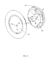
- FIGS. 6-10 depict a monitoring device 100 and interface 200 according to a second example embodiment of the present invention.
- the monitoring device 100 comprises a bottom portion 101 a and top portion 101 b that mate together to house an internal portion 103 that comprises a processor, electronics, one or more transceivers, one or more light emitting LEDs (not shown (that are arranged to be visible through apertures (not shown) in the top portion 101 b ).
- the bottom portion 101 a may include leaf springs 345 that conduct data from a plurality of sensors in or attached to the garment to the electronics (e.g., ADC, DSP, or processor) of the internal portion 103 .
- the interface 200 comprises a receptacle portion 230 that is fixedly attached to member 210 .
- mounting member 210 comprises an elastomeric ring having an aperture therethrough.
- receptacle portion 230 includes three sensor pads 245 (which may comprise rivets that are riveted to the garment and provide a conductive path through the garment).
- Each sensor pad or rivet is electrically connected to one or more sensors attached to or integrated into the garment 15 such as via three respective conductors.
- one of the sensor pads connects to a sensor ground, one connects to an ECG sensor, and one sensor pad connects to a breathing rate sensor.
- Member 210 is fixedly attached to the garment 15 such as by heat bonding or sewn on, although other methods may be used.
- the sensor pads 245 may be connected to sensors in the garment via conductors that extend through the aperture 211 of the member 210 to other locations on the garment (outside the circumference of the ring).
- the receptacle portion 230 includes three inwardly protruding edges 330 and an opening 331 along the perimeter of the receptacle portion 230 .
- the bottom portion 101 a of the monitoring device 100 may include three edge engaging portions 340 that each include an opening 346 and a groove 347 .
- the top portion 101 b of the monitoring portion has a handle 350 to allow the user to urge the monitoring device 100 clockwise or counter-clockwise.
- the user inserts the monitor device 100 into the interface 200 so that the handle 350 enters into the opening 331 along the perimeter of the receptacle portion 230 .
- the three protruding edges 330 of the receptacle portion 230 will be aligned with (in registration with) the three openings 346 of the monitoring device 100 , to thereby allow the bottom portion 101 a of the monitoring device 100 to abut the bottom center of the receptacle portion 230 .
- the user may then rotate the monitoring device 100 approximately thirty degrees clockwise, which causes the three protruding edges 330 to slide into the three grooves 347 of the engaging portions 340 .
- the leaf springs 345 of the monitoring device 100 When fully rotated so that the protruding edges 330 are abutted against the end of the grooves 37 , the leaf springs 345 of the monitoring device 100 will be in contact with the sensor pads 245 of the bottom receptacle portion 230 .
- the grooves 347 may have a slightly narrowing opening so that the monitoring device 100 is held in place with a friction fit.
- the grooves 347 may be spaced away from the back surface of the bottom portion 101 a so that, when the monitoring device 100 is fully inserted, the leaf springs 345 of the monitoring device 100 are urged toward the pads 245 (e.g., rivets) of the receptacle portion 230 .
- edge protrusions 330 may have an indentation (or vertical protrusion)—not shown—that engages a protrusion (or indentation) on the grooves 347 to keep the monitoring device 100 securely attached.
- indentation or vertical protrusion
- FIGS. 11-14 depict a monitoring device 100 and interface 200 according to a third example embodiment of the present invention.
- the monitoring device 100 comprises a bottom portion 101 a and a top portion 101 b that mate together to house an internal portion that comprises a processor, electronics, one or more transceivers, one or more light emitting LEDs (not shown).
- the bottom portion 101 a may include leaf springs 345 (or other sensor pads) that conduct data from a plurality of sensors in or attached to the garment to the electronics (e.g., DSP, ADC ⁇ processor) of the internal portion.
- the electronics e.g., DSP, ADC ⁇ processor
- the device 100 may include a user actuated member 410 which the user may actuate (e.g., press with a finger or thumb) that moves (e.g., toward the center of the device 100 ) to release the monitoring device 100 from the interface 200 to thereby allow removal.
- a user actuated member 410 which the user may actuate (e.g., press with a finger or thumb) that moves (e.g., toward the center of the device 100 ) to release the monitoring device 100 from the interface 200 to thereby allow removal.
- the user actuated member 410 moves laterally when depressed as indicated by the arrow.
- the user actuated member 410 is adjacent to (or connected to) a spring 415 (or other urging member) that urges the user actuated member 410 outward.
- a latching member 420 of the user actuated member 410 moves inward beyond a lip 425 of the interface 200 allowing removal of the monitoring device 100 from the interface 200 .
- the opposite side of the monitoring device 100 includes a protrusion 430 that interfaces with a lip 435 to secure that side of the monitoring device 100 to the interface 200 .
- the remaining aspects of this embodiment are substantially similar to the first embodiment.
- FIG. 15 illustrates an example embodiment of a monitoring device attached to a shirt in which the device/shirt assembly that includes the shirt, a first bonding layer, foam layer, a second bonding layer, a sensor layer (e.g., conductive fabric), a third bonding layer with conductive washers, and a backing layer.
- the device/shirt assembly that includes the shirt, a first bonding layer, foam layer, a second bonding layer, a sensor layer (e.g., conductive fabric), a third bonding layer with conductive washers, and a backing layer.
- the receptacle (and monitoring device) may be formed from nylon or plastic.
- three conductive threads may be attached to the garment or woven therein to connect the three pads 245 of the receptacle to the sensors attached to or integrated into the garment.
- plastic threads may be used to optically conduct the signals to and from the sensors.
Abstract
Provided is a system, method and portable device for monitoring physiological parameters of a person in the field.
Description
This application claims priority to U.S. Provisional Patent Application Ser. No. 61/426,836, filed 23 Dec. 2010, the complete disclosure of which is incorporated herein by reference.
The present invention generally relates to physiological data processing and more particularly, to a system, method and portable device for monitoring physiological parameters of a person in the field.
A person's physiological parameters are traditionally monitored in clinical setting. However, field based monitoring has advantages of being able to monitor the physiological parameters over an extended period of time (e.g., hours or days versus minutes), in a person's typical environment, and during activities of that person. For example, it may be desirable to monitor the vital signals of an athlete (e.g., a professional, collegiate, or high school football, basketball, or baseball player) during a game or during practice for a game and in the athlete's environment (e.g., on the (hot or cold) football field, basketball court, etc.). Similarly, it may be desirable to monitor a patient's vital signs over an extended period of time in the patient's home and/or work place. In addition, monitoring vital signs over extended time periods (in the field) provides more useful information to allow an understanding of a person's physiological state.
It may be desirable for a biosensor sensor system that includes one or more sensors that are integrated or attached to the garment and wherein the biosensor monitoring device is removably attached to the garment.
There are various challenges to removably attaching a monitoring device to a garment. Specifically, the monitoring device must be easily connected to the garment by the user, but in a secure manner so that it does not inadvertently get dislodged. Second, the connections system must satisfy various manufacturability, performance, and usability requirements. Third, it is desirable to reduce or minimize the interference caused by the monitoring device with the user's activities.
These and other advantages may be provided by one or more embodiments of the present invention.
The above objectives and other objectives are obtained by a device for attaching an electronics portion to a garment, comprising:
-
- a housing enclosing at least a portion of the electronics portion;
- an interface configured to be fixedly attached to the garment;
- said housing having a plurality of housing sensor pads;
- said housing configured to be removably attached to said interface; and
- said interface having a plurality of sensor pads positioned to contact the plurality of housing sensor pads when said housing is attached to said interface.
In the following description, for purposes of explanation and not limitation, specific details are set forth, such as particular networks, communication systems, computers, terminals, devices, components, techniques, data and network protocols, software products and systems, operating systems, development interfaces, hardware, etc. in order to provide a thorough understanding of the present invention.
However, it will be apparent to one skilled in the art that the present invention may be practiced in other embodiments that depart from these specific details. Detailed descriptions of well-known networks, communication systems, computers, terminals, devices, components, techniques, data and network protocols, software products and systems, operating systems, development interfaces, and hardware are omitted so as not to obscure the description.
The present invention provides a system, device and method of connecting a monitoring device of a biosensor system to a garment and where one or more sensors are attached or integrated into the garment.
Example embodiments of the present invention may be used to connect a monitoring device to sensors that are attached to or integrated into a garment and have that has the functionality of the BioHarness®, which is commercially available and manufactured by Zephyr Technology of Annapolis, Md. As illustrated in FIG. 1 , the monitoring device 10 is attached to the garment 15 (a shirt) in the chest area. In other embodiments, the monitoring device may be connected to the garment on the upper arm or on the side (under the arm). Example embodiments of the monitoring device 10 may measure heart rate, breathing rate, temperature, activity and/or posture. The monitoring device 10 may include a battery and have a Bluetooth wireless transceiver (and/or one or more other transceivers such as ZigBee (IEEE 8902.154 under Zigbee), ANT, etc.), a processor, and internal memory. Where multiple transceivers are included, two, three or more transceivers may be operational (and operate) concurrently to allow simultaneous communications with different remote devices. The person may wear the device at home and/or work (or in a clinic environment). The data from the biomechanical and physiological sensors (and in some embodiments environmental sensors that measure ambient temperature, humidity, altitude, etc.) is regularly collected and stored in memory. Processing of collected data may be performed by an algorithm executed on the monitoring device 10 or a computer that receives the data from the collection device.
The interface 200 comprises a receptacle portion 230 that is fixedly attached to mounting member 210. In this example, member 210 comprises an elastomeric ring having an aperture 211 therethrough. Receptacle portion 230 includes rim 235 that extends around the perimeter of the receptacle portion except for a lip portion 240. In addition, receptacle portion 230 includes three sensor pads 245, which may comprise rivets that extend through the garment. Each sensor pad is electrically connected to one or more sensors attached to or integrated into the garment 15. In this example, one of the sensor pads connects to a sensor ground, one connects to an ECG sensor, and one sensor pad connects to a breathing rate sensor. Member 210 is fixedly attached to the garment 15 such as by being heat bonded or sewn on, although other methods may be used. Thus, the sensor pads 245 may be connected to sensors in the garment via rivets (or conductors) that extend through the aperture 211 of the member 210 to other locations on the garment (which may be outside the circumference of the ring).
The assembled monitoring device 100 is designed to “snap” into the receptacle portion of the interface 200. The protrusions 145 a-b ensure that the monitoring portion 100 is correctly oriented with respect to the interface 200 to ensure that leaf springs 345 of the monitoring device 100 align with and contact the sensor pads 245 (which may comprise rivets that protrude from the garment through member 210) of the receptacle portion 230 when inserted.
Referring to FIG. 4 , the sides of the receptacle portion 230 are slightly concave and terminate in rim 235. The external lower rim edge 120 of the bottom portion 101 a may have a diameter that is greater than (or that extends radially outward further than) the internal edge of the rim 235 of the receptacle portion 230. Thus, the receptacle portion 230 may be made of plastic or other deformable material that temporarily deforms outward to allow the external lower rim edge 120 to pass through the opening defined by the rim 235 of the receptacle portion 230 (or vice versa). Once in place, the internal edge of the rim 235 of the receptacle portion 230 pinches the external lower rim edge 120 to (1) prevent the monitoring device from being inadvertently dislodged; and (2) to urge the monitoring device 100 toward the receptacle portion. It is worth noting that the outside of the bottom portion 101 is slightly curved at 120 to more easily urge the rim 235 outward when pressure is applied by the user.
During use, the user would press the monitoring device 100 into the interface 200 until the external lower rim edge 120 of the bottom portion 101 a passes through the opening defined by the rim 235 of the receptacle portion 230 and “snaps” into place. To remove the monitoring device 100, the user inserts a finger or thumb under the edge of the monitoring device 100 at the lip portion 240 (and as permitted due to the indentations 140 and 150) and pulls (or leverages) the monitoring device 100 out of the interface 200.
The interface 200 comprises a receptacle portion 230 that is fixedly attached to member 210. In this example, mounting member 210 comprises an elastomeric ring having an aperture therethrough. In addition, receptacle portion 230 includes three sensor pads 245 (which may comprise rivets that are riveted to the garment and provide a conductive path through the garment). Each sensor pad or rivet is electrically connected to one or more sensors attached to or integrated into the garment 15 such as via three respective conductors. In this example, one of the sensor pads connects to a sensor ground, one connects to an ECG sensor, and one sensor pad connects to a breathing rate sensor. Member 210 is fixedly attached to the garment 15 such as by heat bonding or sewn on, although other methods may be used. Thus, the sensor pads 245 may be connected to sensors in the garment via conductors that extend through the aperture 211 of the member 210 to other locations on the garment (outside the circumference of the ring).
In this embodiment, the receptacle portion 230 includes three inwardly protruding edges 330 and an opening 331 along the perimeter of the receptacle portion 230. In addition, the bottom portion 101 a of the monitoring device 100 may include three edge engaging portions 340 that each include an opening 346 and a groove 347. The top portion 101 b of the monitoring portion has a handle 350 to allow the user to urge the monitoring device 100 clockwise or counter-clockwise. To removably attach the monitor 100 to the interface 200, the user inserts the monitor device 100 into the interface 200 so that the handle 350 enters into the opening 331 along the perimeter of the receptacle portion 230. When inserted so that the handle 350 enters into the opening 331 along the perimeter of the receptacle portion 230, the three protruding edges 330 of the receptacle portion 230 will be aligned with (in registration with) the three openings 346 of the monitoring device 100, to thereby allow the bottom portion 101 a of the monitoring device 100 to abut the bottom center of the receptacle portion 230. The user may then rotate the monitoring device 100 approximately thirty degrees clockwise, which causes the three protruding edges 330 to slide into the three grooves 347 of the engaging portions 340. When fully rotated so that the protruding edges 330 are abutted against the end of the grooves 37, the leaf springs 345 of the monitoring device 100 will be in contact with the sensor pads 245 of the bottom receptacle portion 230. The grooves 347 may have a slightly narrowing opening so that the monitoring device 100 is held in place with a friction fit. In addition, the grooves 347 may be spaced away from the back surface of the bottom portion 101 a so that, when the monitoring device 100 is fully inserted, the leaf springs 345 of the monitoring device 100 are urged toward the pads 245 (e.g., rivets) of the receptacle portion 230. Furthermore, the edge protrusions 330 may have an indentation (or vertical protrusion)—not shown—that engages a protrusion (or indentation) on the grooves 347 to keep the monitoring device 100 securely attached. The remaining aspects of this embodiment are substantially similar to the first embodiment.
Referring to FIG. 13 , the user actuated member 410 moves laterally when depressed as indicated by the arrow. The user actuated member 410 is adjacent to (or connected to) a spring 415 (or other urging member) that urges the user actuated member 410 outward. When the user presses the user actuated member 410 against the spring (or other urging member), a latching member 420 of the user actuated member 410 moves inward beyond a lip 425 of the interface 200 allowing removal of the monitoring device 100 from the interface 200. The opposite side of the monitoring device 100 includes a protrusion 430 that interfaces with a lip 435 to secure that side of the monitoring device 100 to the interface 200. The remaining aspects of this embodiment are substantially similar to the first embodiment.
In the above described embodiments, the receptacle (and monitoring device) may be formed from nylon or plastic. In addition, three conductive threads may be attached to the garment or woven therein to connect the three pads 245 of the receptacle to the sensors attached to or integrated into the garment. Alternately or additionally, plastic threads may be used to optically conduct the signals to and from the sensors.
It is to be understood that the foregoing illustrative embodiments have been provided merely for the purpose of explanation and are in no way to be construed as limiting of the invention. Words used herein are words of description and illustration, rather than words of limitation. In addition, the advantages and objectives described herein may not be realized by each and every embodiment practicing the present invention. Further, although the invention has been described herein with reference to particular structure, materials and/or embodiments, the invention is not intended to be limited to the particulars disclosed herein. Rather, the invention extends to all functionally equivalent structures, methods and uses, such as are within the scope of the appended claims. Those skilled in the art, having the benefit of the teachings of this specification, may affect numerous modifications thereto and changes may be made without departing from the scope and spirit of the invention.
Claims (6)
1. An apparatus, comprising:
an electronics portion;
a housing enclosing at least a portion of said electronics portion and comprising a plurality of housing sensor pads, each of the plurality of housing sensor pads comprising a leaf spring;
a garment, at least a portion of said garment having a plurality of stacked layers, one of said plurality of stacked layers being an electrically conductive sensor layer, said sensor layer
configured to measure at least a first physiological signal of a user wearing said garment;
an interface comprising a receptacle portion and a plurality of interface sensor pads, the interface configured to be fixedly attached to said garment in a chest area, each of the plurality of interface sensor pads comprising a protrusion;
said housing configured to be removably attached to said interface by snapping into the receptacle portion of the interface, wherein the plurality of protrusions are configured to orient the housing in an attached state with respect to the interface to ensure that each leaf spring of the plurality of housing sensor pads aligns with and contacts the protrusion of the plurality interface sensor pads when the housing is snapped into the interface,
the plurality of interface sensor pads including a first interface sensor pad coupled to a sensor ground, a second interface sensor pad coupled to an ECG sensor, and a third interface sensor pad coupled to a breathing rate sensor;
at least one of said interface sensor pads being electrically coupled to said sensor layer.
2. The apparatus of claim 1 , wherein said housing includes a user actuated member having a first state in which said user actuated member engages said interface and a second state in which said user actuated member does not engage said interface and wherein said user actuated member is configured to transition from said first state to said second state by actuation of the user.
3. The apparatus of claim 1 , wherein said interface is fixedly attached to said garment by any of heat bonding or sewing, or a combination thereof.
4. The apparatus of claim 1 , wherein said electronics portion comprises:
a battery,
at least one wireless transceiver,
a processor,
at least one light emitting LED, and
an internal memory.
5. The apparatus of claim 4 , wherein said at least one wireless transceiver comprises:
at least two wireless transceivers, each operable to communicate simultaneously with at least one remote device.
6. The apparatus of claim 1 , wherein said apparatus is configured to measure at least one of heart rate, temperature, activity, ECG data, breathing rate, or posture.
Priority Applications (1)
| Application Number | Priority Date | Filing Date | Title |
|---|---|---|---|
| US13/331,544 US9775561B2 (en) | 2010-12-23 | 2011-12-20 | System method and device for monitoring physiological parameters of a person |
Applications Claiming Priority (2)
| Application Number | Priority Date | Filing Date | Title |
|---|---|---|---|
| US201061426836P | 2010-12-23 | 2010-12-23 | |
| US13/331,544 US9775561B2 (en) | 2010-12-23 | 2011-12-20 | System method and device for monitoring physiological parameters of a person |
Publications (2)
| Publication Number | Publication Date |
|---|---|
| US20120165645A1 US20120165645A1 (en) | 2012-06-28 |
| US9775561B2 true US9775561B2 (en) | 2017-10-03 |
Family
ID=46317942
Family Applications (1)
| Application Number | Title | Priority Date | Filing Date |
|---|---|---|---|
| US13/331,544 Active 2034-01-08 US9775561B2 (en) | 2010-12-23 | 2011-12-20 | System method and device for monitoring physiological parameters of a person |
Country Status (1)
| Country | Link |
|---|---|
| US (1) | US9775561B2 (en) |
Cited By (5)
| Publication number | Priority date | Publication date | Assignee | Title |
|---|---|---|---|---|
| US20170251946A1 (en) * | 2013-09-25 | 2017-09-07 | Bardy Diagnostics, Inc. | Wearable electrocardiography and physiology monitoring ensemble |
| US20180049698A1 (en) * | 2016-08-18 | 2018-02-22 | MAD Apparel, Inc. | Garment with conductive thread exposed on both sides |
| US20190150527A1 (en) * | 2011-09-27 | 2019-05-23 | Under Armour, Inc. | Electronic Housing and Sensor Connection Arrangement |
| US20210135416A1 (en) * | 2019-10-30 | 2021-05-06 | J-Mex Inc. | Bonding device, bonding structure for wearable device and node device for forming sensing point on signal connecting line thereof |
| USD932008S1 (en) * | 2019-11-07 | 2021-09-28 | Wuxi Kaishun Medical Device Manufacturing Co., Ltd. | Stethoscope head |
Families Citing this family (75)
| Publication number | Priority date | Publication date | Assignee | Title |
|---|---|---|---|---|
| US8909318B2 (en) * | 2011-03-18 | 2014-12-09 | Nike Inc. | Apparel for physiological telemetry during athletics |
| US9247907B2 (en) | 2011-09-27 | 2016-02-02 | Under Armour, Inc. | Garment with receptacle and electronic module |
| US8948839B1 (en) | 2013-08-06 | 2015-02-03 | L.I.F.E. Corporation S.A. | Compression garments having stretchable and conductive ink |
| US9817440B2 (en) | 2012-09-11 | 2017-11-14 | L.I.F.E. Corporation S.A. | Garments having stretchable and conductive ink |
| US10201310B2 (en) | 2012-09-11 | 2019-02-12 | L.I.F.E. Corporation S.A. | Calibration packaging apparatuses for physiological monitoring garments |
| US10462898B2 (en) | 2012-09-11 | 2019-10-29 | L.I.F.E. Corporation S.A. | Physiological monitoring garments |
| US8945328B2 (en) | 2012-09-11 | 2015-02-03 | L.I.F.E. Corporation S.A. | Methods of making garments having stretchable and conductive ink |
| WO2014041032A1 (en) | 2012-09-11 | 2014-03-20 | L.I.F.E. Corporation S.A. | Wearable communication platform |
| US10159440B2 (en) | 2014-03-10 | 2018-12-25 | L.I.F.E. Corporation S.A. | Physiological monitoring garments |
| US11246213B2 (en) | 2012-09-11 | 2022-02-08 | L.I.F.E. Corporation S.A. | Physiological monitoring garments |
| DE102012218068A1 (en) * | 2012-10-02 | 2014-04-03 | Adidas Ag | OF CLOTHING |
| US9498128B2 (en) | 2012-11-14 | 2016-11-22 | MAD Apparel, Inc. | Wearable architecture and methods for performance monitoring, analysis, and feedback |
| US11944441B2 (en) | 2012-12-31 | 2024-04-02 | Suunto Oy | Electro-mechanic assembly and integrated snap connectors |
| US11058338B2 (en) | 2012-12-31 | 2021-07-13 | Suunto Oy | Electrode assembly |
| FI125324B (en) * | 2012-12-31 | 2015-08-31 | Suunto Oy | Built-in snap fastener |
| US9861291B2 (en) | 2012-12-31 | 2018-01-09 | Suunto Oy | Electrode assembly |
| US9402429B2 (en) * | 2013-03-14 | 2016-08-02 | Nike, Inc. | Telemetrically enhanced athletic apparel |
| US10463269B2 (en) | 2013-09-25 | 2019-11-05 | Bardy Diagnostics, Inc. | System and method for machine-learning-based atrial fibrillation detection |
| US9655538B2 (en) | 2013-09-25 | 2017-05-23 | Bardy Diagnostics, Inc. | Self-authenticating electrocardiography monitoring circuit |
| US10433751B2 (en) | 2013-09-25 | 2019-10-08 | Bardy Diagnostics, Inc. | System and method for facilitating a cardiac rhythm disorder diagnosis based on subcutaneous cardiac monitoring data |
| WO2015048194A1 (en) | 2013-09-25 | 2015-04-02 | Bardy Diagnostics, Inc. | Self-contained personal air flow sensing monitor |
| US10251576B2 (en) | 2013-09-25 | 2019-04-09 | Bardy Diagnostics, Inc. | System and method for ECG data classification for use in facilitating diagnosis of cardiac rhythm disorders with the aid of a digital computer |
| US10736531B2 (en) | 2013-09-25 | 2020-08-11 | Bardy Diagnostics, Inc. | Subcutaneous insertable cardiac monitor optimized for long term, low amplitude electrocardiographic data collection |
| US9619660B1 (en) | 2013-09-25 | 2017-04-11 | Bardy Diagnostics, Inc. | Computer-implemented system for secure physiological data collection and processing |
| US10736529B2 (en) | 2013-09-25 | 2020-08-11 | Bardy Diagnostics, Inc. | Subcutaneous insertable electrocardiography monitor |
| US10165946B2 (en) | 2013-09-25 | 2019-01-01 | Bardy Diagnostics, Inc. | Computer-implemented system and method for providing a personal mobile device-triggered medical intervention |
| US10667711B1 (en) | 2013-09-25 | 2020-06-02 | Bardy Diagnostics, Inc. | Contact-activated extended wear electrocardiography and physiological sensor monitor recorder |
| US10624551B2 (en) | 2013-09-25 | 2020-04-21 | Bardy Diagnostics, Inc. | Insertable cardiac monitor for use in performing long term electrocardiographic monitoring |
| US9717432B2 (en) | 2013-09-25 | 2017-08-01 | Bardy Diagnostics, Inc. | Extended wear electrocardiography patch using interlaced wire electrodes |
| US10820801B2 (en) | 2013-09-25 | 2020-11-03 | Bardy Diagnostics, Inc. | Electrocardiography monitor configured for self-optimizing ECG data compression |
| US9504423B1 (en) | 2015-10-05 | 2016-11-29 | Bardy Diagnostics, Inc. | Method for addressing medical conditions through a wearable health monitor with the aid of a digital computer |
| US10799137B2 (en) | 2013-09-25 | 2020-10-13 | Bardy Diagnostics, Inc. | System and method for facilitating a cardiac rhythm disorder diagnosis with the aid of a digital computer |
| US11213237B2 (en) | 2013-09-25 | 2022-01-04 | Bardy Diagnostics, Inc. | System and method for secure cloud-based physiological data processing and delivery |
| US10433748B2 (en) | 2013-09-25 | 2019-10-08 | Bardy Diagnostics, Inc. | Extended wear electrocardiography and physiological sensor monitor |
| US9737224B2 (en) | 2013-09-25 | 2017-08-22 | Bardy Diagnostics, Inc. | Event alerting through actigraphy embedded within electrocardiographic data |
| US9408545B2 (en) | 2013-09-25 | 2016-08-09 | Bardy Diagnostics, Inc. | Method for efficiently encoding and compressing ECG data optimized for use in an ambulatory ECG monitor |
| US11723575B2 (en) | 2013-09-25 | 2023-08-15 | Bardy Diagnostics, Inc. | Electrocardiography patch |
| US9364155B2 (en) | 2013-09-25 | 2016-06-14 | Bardy Diagnostics, Inc. | Self-contained personal air flow sensing monitor |
| US9730593B2 (en) | 2013-09-25 | 2017-08-15 | Bardy Diagnostics, Inc. | Extended wear ambulatory electrocardiography and physiological sensor monitor |
| US9700227B2 (en) | 2013-09-25 | 2017-07-11 | Bardy Diagnostics, Inc. | Ambulatory electrocardiography monitoring patch optimized for capturing low amplitude cardiac action potential propagation |
| US9433367B2 (en) | 2013-09-25 | 2016-09-06 | Bardy Diagnostics, Inc. | Remote interfacing of extended wear electrocardiography and physiological sensor monitor |
| US10806360B2 (en) | 2013-09-25 | 2020-10-20 | Bardy Diagnostics, Inc. | Extended wear ambulatory electrocardiography and physiological sensor monitor |
| US9345414B1 (en) | 2013-09-25 | 2016-05-24 | Bardy Diagnostics, Inc. | Method for providing dynamic gain over electrocardiographic data with the aid of a digital computer |
| US9717433B2 (en) | 2013-09-25 | 2017-08-01 | Bardy Diagnostics, Inc. | Ambulatory electrocardiography monitoring patch optimized for capturing low amplitude cardiac action potential propagation |
| US20190167139A1 (en) | 2017-12-05 | 2019-06-06 | Gust H. Bardy | Subcutaneous P-Wave Centric Insertable Cardiac Monitor For Long Term Electrocardiographic Monitoring |
| US9775536B2 (en) | 2013-09-25 | 2017-10-03 | Bardy Diagnostics, Inc. | Method for constructing a stress-pliant physiological electrode assembly |
| US9615763B2 (en) | 2013-09-25 | 2017-04-11 | Bardy Diagnostics, Inc. | Ambulatory electrocardiography monitor recorder optimized for capturing low amplitude cardiac action potential propagation |
| US10888239B2 (en) | 2013-09-25 | 2021-01-12 | Bardy Diagnostics, Inc. | Remote interfacing electrocardiography patch |
| US9408551B2 (en) | 2013-11-14 | 2016-08-09 | Bardy Diagnostics, Inc. | System and method for facilitating diagnosis of cardiac rhythm disorders with the aid of a digital computer |
| US9433380B1 (en) | 2013-09-25 | 2016-09-06 | Bardy Diagnostics, Inc. | Extended wear electrocardiography patch |
| JP6233804B2 (en) * | 2013-10-25 | 2017-11-22 | セイコーインスツル株式会社 | Portable electronic devices |
| US10292652B2 (en) | 2013-11-23 | 2019-05-21 | MAD Apparel, Inc. | System and method for monitoring biometric signals |
| US10321832B2 (en) | 2013-11-23 | 2019-06-18 | MAD Apparel, Inc. | System and method for monitoring biometric signals |
| US11219396B2 (en) | 2013-11-23 | 2022-01-11 | MAD Apparel, Inc. | System and method for monitoring biometric signals |
| WO2015103620A1 (en) | 2014-01-06 | 2015-07-09 | Andrea Aliverti | Systems and methods to automatically determine garment fit |
| US10617354B2 (en) | 2014-04-29 | 2020-04-14 | MAD Apparel, Inc. | Biometric electrode system and method of manufacture |
| US10398376B2 (en) | 2014-06-17 | 2019-09-03 | MAD Apparel, Inc. | Garment integrated electrical interface system and method of manufacture |
| CA2958227A1 (en) * | 2014-08-15 | 2016-02-18 | Nonin Medical, Inc. | Detachable physiological sensing device |
| AU2015323905A1 (en) * | 2014-09-29 | 2017-04-27 | MAD Apparel, Inc. | Garment integrated electrical interface system and method of manufacture |
| US9913611B2 (en) | 2014-11-10 | 2018-03-13 | MAD Apparel, Inc. | Garment integrated sensing system and method |
| USD753832S1 (en) * | 2014-11-11 | 2016-04-12 | Kinpo Electronics, Inc. | Apparatus for measuring physiological signal |
| WO2017007752A1 (en) | 2015-07-06 | 2017-01-12 | Metritrack, Inc. | Sensor assembly for use with a positional tracking system and method of manufacture |
| KR102593337B1 (en) | 2015-07-20 | 2023-10-23 | 엘.아이.에프.이. 코포레이션 에스.에이. | Flexible fabric ribbon connectors for clothing with sensors and electronics |
| CN105662337B (en) * | 2015-12-30 | 2018-08-17 | 博迪加科技(北京)有限公司 | A kind of signal processing apparatus and intelligent clothing |
| CN109640820A (en) | 2016-07-01 | 2019-04-16 | 立芙公司 | The living things feature recognition carried out by the clothes with multiple sensors |
| WO2018104329A1 (en) * | 2016-12-05 | 2018-06-14 | Vexatec Ag | System for measuring physiological data |
| TWD190209S (en) * | 2017-06-29 | 2018-05-01 | 大立健康科技股份有限公司 | Electrocardiography machine |
| CA3074680A1 (en) * | 2017-09-05 | 2019-03-14 | Breathevision Ltd. | Monitoring system |
| US10727956B2 (en) * | 2017-09-06 | 2020-07-28 | Hill-Rom Services, Inc. | Wireless sensors in medical environments |
| JP2021510000A (en) | 2018-01-06 | 2021-04-08 | マイアント インコーポレイテッドMyant Inc. | Electronics-woven fabric interconnection methods and systems |
| US11051757B2 (en) * | 2019-01-31 | 2021-07-06 | Preventice Technologies, Inc. | Self-aligning device to patch interface |
| US11696681B2 (en) | 2019-07-03 | 2023-07-11 | Bardy Diagnostics Inc. | Configurable hardware platform for physiological monitoring of a living body |
| US11096579B2 (en) | 2019-07-03 | 2021-08-24 | Bardy Diagnostics, Inc. | System and method for remote ECG data streaming in real-time |
| US11116451B2 (en) | 2019-07-03 | 2021-09-14 | Bardy Diagnostics, Inc. | Subcutaneous P-wave centric insertable cardiac monitor with energy harvesting capabilities |
| CN113576483A (en) * | 2021-08-06 | 2021-11-02 | 中国科学院苏州生物医学工程技术研究所 | Wearable equipment |
Citations (23)
| Publication number | Priority date | Publication date | Assignee | Title |
|---|---|---|---|---|
| US4889131A (en) * | 1987-12-03 | 1989-12-26 | American Health Products, Inc. | Portable belt monitor of physiological functions and sensors therefor |
| US5657201A (en) * | 1995-11-06 | 1997-08-12 | Teletransactions, Inc. | Portable data collection terminal including arm mounting assembly |
| US20010044573A1 (en) * | 1999-02-05 | 2001-11-22 | Samir Manoli | EEG electrode and EEG electrode locator assembly |
| US20020128686A1 (en) * | 1999-01-11 | 2002-09-12 | Minogue Michael Conor | Electrotherapy device and method |
| US20020124295A1 (en) * | 2000-10-30 | 2002-09-12 | Loel Fenwick | Clothing apparatus, carrier for a biophysical sensor, and patient alarm system |
| US6895261B1 (en) * | 2000-07-13 | 2005-05-17 | Thomas R. Palamides | Portable, wireless communication apparatus integrated with garment |
| US20070088419A1 (en) * | 2005-10-13 | 2007-04-19 | Fiorina Mark A | Conductive pad assembly for electrical therapy device |
| US20070089800A1 (en) * | 2005-10-24 | 2007-04-26 | Sensatex, Inc. | Fabrics and Garments with Information Infrastructure |
| US20070279852A1 (en) * | 2004-02-27 | 2007-12-06 | Daniel Simon R | Wearable Modular Interface Strap |
| US20070285868A1 (en) * | 2006-06-08 | 2007-12-13 | Suunto Oy | Sensor arrangement |
| US20080108890A1 (en) * | 2006-11-07 | 2008-05-08 | Leadtek Research Inc. | Physiological data measuring apparatus and measuring strip |
| US20080288026A1 (en) * | 2005-11-30 | 2008-11-20 | Koninklijke Philips Electronics N. V. | Electro-Mechanical Connector for Thin Medical Monitoring Patch |
| WO2009112976A1 (en) * | 2008-03-10 | 2009-09-17 | Koninklijke Philips Electronics N.V. | Cellphone handset with cover for an ecg monitoring system |
| USD603521S1 (en) * | 2008-12-03 | 2009-11-03 | Suunto Oy | Module of a heart rate belt |
| US20100185398A1 (en) * | 2009-01-22 | 2010-07-22 | Under Armour, Inc. | System and Method for Monitoring Athletic Performance |
| US8083693B1 (en) * | 2007-03-30 | 2011-12-27 | Perseus Athletics, LLC | Monitoring posture |
| US20120078127A1 (en) * | 2010-09-23 | 2012-03-29 | Mcdonald David | Physiological status monitoring system |
| US20120101396A1 (en) * | 2008-03-10 | 2012-04-26 | Koninklijke Philips Electronics N.V. | Continuous outpatinet ecg monitoring system |
| US20120246795A1 (en) * | 2011-03-31 | 2012-10-04 | Adidas Ag | Sensor Garment |
| US20120330126A1 (en) * | 2009-12-23 | 2012-12-27 | Delta, Dansk Elektronik, Lys Og Akustik | Monitoring device for attachment to a surface of a subject |
| US20130019383A1 (en) * | 2011-07-19 | 2013-01-24 | Polar Electro Oy | Exercise Apparel |
| US8909318B2 (en) * | 2011-03-18 | 2014-12-09 | Nike Inc. | Apparel for physiological telemetry during athletics |
| US9119594B2 (en) * | 2011-09-27 | 2015-09-01 | Under Armour, Inc. | Electronic housing and sensor connection arrangement |
-
2011
- 2011-12-20 US US13/331,544 patent/US9775561B2/en active Active
Patent Citations (23)
| Publication number | Priority date | Publication date | Assignee | Title |
|---|---|---|---|---|
| US4889131A (en) * | 1987-12-03 | 1989-12-26 | American Health Products, Inc. | Portable belt monitor of physiological functions and sensors therefor |
| US5657201A (en) * | 1995-11-06 | 1997-08-12 | Teletransactions, Inc. | Portable data collection terminal including arm mounting assembly |
| US20020128686A1 (en) * | 1999-01-11 | 2002-09-12 | Minogue Michael Conor | Electrotherapy device and method |
| US20010044573A1 (en) * | 1999-02-05 | 2001-11-22 | Samir Manoli | EEG electrode and EEG electrode locator assembly |
| US6895261B1 (en) * | 2000-07-13 | 2005-05-17 | Thomas R. Palamides | Portable, wireless communication apparatus integrated with garment |
| US20020124295A1 (en) * | 2000-10-30 | 2002-09-12 | Loel Fenwick | Clothing apparatus, carrier for a biophysical sensor, and patient alarm system |
| US20070279852A1 (en) * | 2004-02-27 | 2007-12-06 | Daniel Simon R | Wearable Modular Interface Strap |
| US20070088419A1 (en) * | 2005-10-13 | 2007-04-19 | Fiorina Mark A | Conductive pad assembly for electrical therapy device |
| US20070089800A1 (en) * | 2005-10-24 | 2007-04-26 | Sensatex, Inc. | Fabrics and Garments with Information Infrastructure |
| US20080288026A1 (en) * | 2005-11-30 | 2008-11-20 | Koninklijke Philips Electronics N. V. | Electro-Mechanical Connector for Thin Medical Monitoring Patch |
| US20070285868A1 (en) * | 2006-06-08 | 2007-12-13 | Suunto Oy | Sensor arrangement |
| US20080108890A1 (en) * | 2006-11-07 | 2008-05-08 | Leadtek Research Inc. | Physiological data measuring apparatus and measuring strip |
| US8083693B1 (en) * | 2007-03-30 | 2011-12-27 | Perseus Athletics, LLC | Monitoring posture |
| WO2009112976A1 (en) * | 2008-03-10 | 2009-09-17 | Koninklijke Philips Electronics N.V. | Cellphone handset with cover for an ecg monitoring system |
| US20120101396A1 (en) * | 2008-03-10 | 2012-04-26 | Koninklijke Philips Electronics N.V. | Continuous outpatinet ecg monitoring system |
| USD603521S1 (en) * | 2008-12-03 | 2009-11-03 | Suunto Oy | Module of a heart rate belt |
| US20100185398A1 (en) * | 2009-01-22 | 2010-07-22 | Under Armour, Inc. | System and Method for Monitoring Athletic Performance |
| US20120330126A1 (en) * | 2009-12-23 | 2012-12-27 | Delta, Dansk Elektronik, Lys Og Akustik | Monitoring device for attachment to a surface of a subject |
| US20120078127A1 (en) * | 2010-09-23 | 2012-03-29 | Mcdonald David | Physiological status monitoring system |
| US8909318B2 (en) * | 2011-03-18 | 2014-12-09 | Nike Inc. | Apparel for physiological telemetry during athletics |
| US20120246795A1 (en) * | 2011-03-31 | 2012-10-04 | Adidas Ag | Sensor Garment |
| US20130019383A1 (en) * | 2011-07-19 | 2013-01-24 | Polar Electro Oy | Exercise Apparel |
| US9119594B2 (en) * | 2011-09-27 | 2015-09-01 | Under Armour, Inc. | Electronic housing and sensor connection arrangement |
Cited By (8)
| Publication number | Priority date | Publication date | Assignee | Title |
|---|---|---|---|---|
| US20190150527A1 (en) * | 2011-09-27 | 2019-05-23 | Under Armour, Inc. | Electronic Housing and Sensor Connection Arrangement |
| US10617156B2 (en) * | 2011-09-27 | 2020-04-14 | Under Armour, Inc. | Electronic housing and sensor connection arrangement |
| US20170251946A1 (en) * | 2013-09-25 | 2017-09-07 | Bardy Diagnostics, Inc. | Wearable electrocardiography and physiology monitoring ensemble |
| US10251575B2 (en) * | 2013-09-25 | 2019-04-09 | Bardy Diagnostics, Inc. | Wearable electrocardiography and physiology monitoring ensemble |
| US20180049698A1 (en) * | 2016-08-18 | 2018-02-22 | MAD Apparel, Inc. | Garment with conductive thread exposed on both sides |
| US10925540B2 (en) * | 2016-08-18 | 2021-02-23 | MAD Apparel, Inc. | Garment with conductive thread exposed on both sides |
| US20210135416A1 (en) * | 2019-10-30 | 2021-05-06 | J-Mex Inc. | Bonding device, bonding structure for wearable device and node device for forming sensing point on signal connecting line thereof |
| USD932008S1 (en) * | 2019-11-07 | 2021-09-28 | Wuxi Kaishun Medical Device Manufacturing Co., Ltd. | Stethoscope head |
Also Published As
| Publication number | Publication date |
|---|---|
| US20120165645A1 (en) | 2012-06-28 |
Similar Documents
| Publication | Publication Date | Title |
|---|---|---|
| US9775561B2 (en) | System method and device for monitoring physiological parameters of a person | |
| US11464432B2 (en) | Monitoring device for attachment to a surface of a subject | |
| US10575741B2 (en) | Wearable biometric information measurement device | |
| US20230210417A1 (en) | Wrist and finger worn pulse oximetry system | |
| US20220101992A1 (en) | Sensor patch and related smart device, systems, and methods | |
| CN101330866B (en) | Single use pulse oximeter | |
| CN101330865B (en) | Single use pulse oximeter | |
| US20170071469A1 (en) | Method and Device for Patient Monitoring Using Dynamic Multi-Function Device | |
| US20150065843A1 (en) | Apparel for physiological telemetry during athletics | |
| JP6233804B2 (en) | Portable electronic devices | |
| EP4021293A1 (en) | Vital signs or health monitoring systems and methods | |
| KR102391913B1 (en) | Biometric information measurement device | |
| AU2013328589A1 (en) | A monitoring device | |
| KR101745760B1 (en) | Digital clothing capable of sensing biological information and health care tracking system using the same | |
| US20150335947A1 (en) | Sports device and system | |
| US11259580B2 (en) | Health monitoring garment and system | |
| WO2022087254A1 (en) | Reconfigurable device for monitoring health metrics | |
| Shaw et al. | Warfighter physiological and environmental monitoring: a study for the US Army Research Institute in Environmental Medicine and the Soldier Systems Center | |
| KR102412922B1 (en) | Body temperature charging biometric emergency ring | |
| KR101776366B1 (en) | Digital band capable of sensing biological information | |
| Bianchi et al. | The HELICOPTER project: Wireless sensor network for multi-user behavioral monitoring | |
| CN216417173U (en) | Foot ring for monitoring state of illness | |
| KR102473330B1 (en) | Ring-shaped wearable device for health monitoring | |
| AU2019473059B2 (en) | Wearable sensor device | |
| US20230397871A1 (en) | Sensing connector assembly and system comprising said sensing connector assembly |
Legal Events
| Date | Code | Title | Description |
|---|---|---|---|
| AS | Assignment |
Owner name: ZEPHYR TECHNOLOGY CORPORATION, MARYLAND Free format text: ASSIGNMENT OF ASSIGNORS INTEREST;ASSIGNORS:RUSSELL, BRIAN;WOODWARD, JONATHAN;RADTKE, WILLIAM;AND OTHERS;SIGNING DATES FROM 20111207 TO 20111213;REEL/FRAME:027423/0454 |
|
| STCF | Information on status: patent grant |
Free format text: PATENTED CASE |
|
| MAFP | Maintenance fee payment |
Free format text: PAYMENT OF MAINTENANCE FEE, 4TH YEAR, LARGE ENTITY (ORIGINAL EVENT CODE: M1551); ENTITY STATUS OF PATENT OWNER: LARGE ENTITY Year of fee payment: 4 |