US9775672B2 - Bi-polar surgical instrument - Google Patents
Bi-polar surgical instrument Download PDFInfo
- Publication number
- US9775672B2 US9775672B2 US13/975,494 US201313975494A US9775672B2 US 9775672 B2 US9775672 B2 US 9775672B2 US 201313975494 A US201313975494 A US 201313975494A US 9775672 B2 US9775672 B2 US 9775672B2
- Authority
- US
- United States
- Prior art keywords
- fluid
- electrodes
- electrode
- shaft member
- surgical device
- Prior art date
- Legal status (The legal status is an assumption and is not a legal conclusion. Google has not performed a legal analysis and makes no representation as to the accuracy of the status listed.)
- Active, expires
Links
Images


Classifications
-
- A—HUMAN NECESSITIES
- A61—MEDICAL OR VETERINARY SCIENCE; HYGIENE
- A61B—DIAGNOSIS; SURGERY; IDENTIFICATION
- A61B18/00—Surgical instruments, devices or methods for transferring non-mechanical forms of energy to or from the body
- A61B18/04—Surgical instruments, devices or methods for transferring non-mechanical forms of energy to or from the body by heating
- A61B18/12—Surgical instruments, devices or methods for transferring non-mechanical forms of energy to or from the body by heating by passing a current through the tissue to be heated, e.g. high-frequency current
- A61B18/14—Probes or electrodes therefor
- A61B18/148—Probes or electrodes therefor having a short, rigid shaft for accessing the inner body transcutaneously, e.g. for neurosurgery or arthroscopy
-
- A—HUMAN NECESSITIES
- A61—MEDICAL OR VETERINARY SCIENCE; HYGIENE
- A61B—DIAGNOSIS; SURGERY; IDENTIFICATION
- A61B18/00—Surgical instruments, devices or methods for transferring non-mechanical forms of energy to or from the body
- A61B18/04—Surgical instruments, devices or methods for transferring non-mechanical forms of energy to or from the body by heating
- A61B18/12—Surgical instruments, devices or methods for transferring non-mechanical forms of energy to or from the body by heating by passing a current through the tissue to be heated, e.g. high-frequency current
- A61B18/14—Probes or electrodes therefor
- A61B18/1482—Probes or electrodes therefor having a long rigid shaft for accessing the inner body transcutaneously in minimal invasive surgery, e.g. laparoscopy
-
- A—HUMAN NECESSITIES
- A61—MEDICAL OR VETERINARY SCIENCE; HYGIENE
- A61B—DIAGNOSIS; SURGERY; IDENTIFICATION
- A61B18/00—Surgical instruments, devices or methods for transferring non-mechanical forms of energy to or from the body
- A61B18/04—Surgical instruments, devices or methods for transferring non-mechanical forms of energy to or from the body by heating
- A61B18/12—Surgical instruments, devices or methods for transferring non-mechanical forms of energy to or from the body by heating by passing a current through the tissue to be heated, e.g. high-frequency current
- A61B18/14—Probes or electrodes therefor
- A61B18/1492—Probes or electrodes therefor having a flexible, catheter-like structure, e.g. for heart ablation
-
- A—HUMAN NECESSITIES
- A61—MEDICAL OR VETERINARY SCIENCE; HYGIENE
- A61B—DIAGNOSIS; SURGERY; IDENTIFICATION
- A61B18/00—Surgical instruments, devices or methods for transferring non-mechanical forms of energy to or from the body
- A61B2018/00005—Cooling or heating of the probe or tissue immediately surrounding the probe
- A61B2018/00011—Cooling or heating of the probe or tissue immediately surrounding the probe with fluids
- A61B2018/00029—Cooling or heating of the probe or tissue immediately surrounding the probe with fluids open
- A61B2018/00035—Cooling or heating of the probe or tissue immediately surrounding the probe with fluids open with return means
-
- A—HUMAN NECESSITIES
- A61—MEDICAL OR VETERINARY SCIENCE; HYGIENE
- A61B—DIAGNOSIS; SURGERY; IDENTIFICATION
- A61B18/00—Surgical instruments, devices or methods for transferring non-mechanical forms of energy to or from the body
- A61B2018/00053—Mechanical features of the instrument of device
- A61B2018/00166—Multiple lumina
-
- A—HUMAN NECESSITIES
- A61—MEDICAL OR VETERINARY SCIENCE; HYGIENE
- A61B—DIAGNOSIS; SURGERY; IDENTIFICATION
- A61B18/00—Surgical instruments, devices or methods for transferring non-mechanical forms of energy to or from the body
- A61B2018/00315—Surgical instruments, devices or methods for transferring non-mechanical forms of energy to or from the body for treatment of particular body parts
- A61B2018/00339—Spine, e.g. intervertebral disc
-
- A—HUMAN NECESSITIES
- A61—MEDICAL OR VETERINARY SCIENCE; HYGIENE
- A61B—DIAGNOSIS; SURGERY; IDENTIFICATION
- A61B18/00—Surgical instruments, devices or methods for transferring non-mechanical forms of energy to or from the body
- A61B2018/00315—Surgical instruments, devices or methods for transferring non-mechanical forms of energy to or from the body for treatment of particular body parts
- A61B2018/00345—Vascular system
- A61B2018/00404—Blood vessels other than those in or around the heart
-
- A—HUMAN NECESSITIES
- A61—MEDICAL OR VETERINARY SCIENCE; HYGIENE
- A61B—DIAGNOSIS; SURGERY; IDENTIFICATION
- A61B18/00—Surgical instruments, devices or methods for transferring non-mechanical forms of energy to or from the body
- A61B2018/00571—Surgical instruments, devices or methods for transferring non-mechanical forms of energy to or from the body for achieving a particular surgical effect
- A61B2018/00589—Coagulation
-
- A—HUMAN NECESSITIES
- A61—MEDICAL OR VETERINARY SCIENCE; HYGIENE
- A61B—DIAGNOSIS; SURGERY; IDENTIFICATION
- A61B18/00—Surgical instruments, devices or methods for transferring non-mechanical forms of energy to or from the body
- A61B2018/00571—Surgical instruments, devices or methods for transferring non-mechanical forms of energy to or from the body for achieving a particular surgical effect
- A61B2018/00595—Cauterization
-
- A—HUMAN NECESSITIES
- A61—MEDICAL OR VETERINARY SCIENCE; HYGIENE
- A61B—DIAGNOSIS; SURGERY; IDENTIFICATION
- A61B18/00—Surgical instruments, devices or methods for transferring non-mechanical forms of energy to or from the body
- A61B2018/0091—Handpieces of the surgical instrument or device
- A61B2018/00916—Handpieces of the surgical instrument or device with means for switching or controlling the main function of the instrument or device
- A61B2018/0094—Types of switches or controllers
- A61B2018/00946—Types of switches or controllers slidable
-
- A—HUMAN NECESSITIES
- A61—MEDICAL OR VETERINARY SCIENCE; HYGIENE
- A61B—DIAGNOSIS; SURGERY; IDENTIFICATION
- A61B18/00—Surgical instruments, devices or methods for transferring non-mechanical forms of energy to or from the body
- A61B18/04—Surgical instruments, devices or methods for transferring non-mechanical forms of energy to or from the body by heating
- A61B18/12—Surgical instruments, devices or methods for transferring non-mechanical forms of energy to or from the body by heating by passing a current through the tissue to be heated, e.g. high-frequency current
- A61B18/1206—Generators therefor
- A61B2018/1246—Generators therefor characterised by the output polarity
- A61B2018/126—Generators therefor characterised by the output polarity bipolar
-
- A—HUMAN NECESSITIES
- A61—MEDICAL OR VETERINARY SCIENCE; HYGIENE
- A61B—DIAGNOSIS; SURGERY; IDENTIFICATION
- A61B18/00—Surgical instruments, devices or methods for transferring non-mechanical forms of energy to or from the body
- A61B18/04—Surgical instruments, devices or methods for transferring non-mechanical forms of energy to or from the body by heating
- A61B18/12—Surgical instruments, devices or methods for transferring non-mechanical forms of energy to or from the body by heating by passing a current through the tissue to be heated, e.g. high-frequency current
- A61B18/14—Probes or electrodes therefor
- A61B2018/1405—Electrodes having a specific shape
- A61B2018/1422—Hook
-
- A—HUMAN NECESSITIES
- A61—MEDICAL OR VETERINARY SCIENCE; HYGIENE
- A61B—DIAGNOSIS; SURGERY; IDENTIFICATION
- A61B18/00—Surgical instruments, devices or methods for transferring non-mechanical forms of energy to or from the body
- A61B18/04—Surgical instruments, devices or methods for transferring non-mechanical forms of energy to or from the body by heating
- A61B18/12—Surgical instruments, devices or methods for transferring non-mechanical forms of energy to or from the body by heating by passing a current through the tissue to be heated, e.g. high-frequency current
- A61B18/14—Probes or electrodes therefor
- A61B2018/1465—Deformable electrodes
-
- A—HUMAN NECESSITIES
- A61—MEDICAL OR VETERINARY SCIENCE; HYGIENE
- A61B—DIAGNOSIS; SURGERY; IDENTIFICATION
- A61B2218/00—Details of surgical instruments, devices or methods for transferring non-mechanical forms of energy to or from the body
- A61B2218/001—Details of surgical instruments, devices or methods for transferring non-mechanical forms of energy to or from the body having means for irrigation and/or aspiration of substances to and/or from the surgical site
- A61B2218/002—Irrigation
-
- A—HUMAN NECESSITIES
- A61—MEDICAL OR VETERINARY SCIENCE; HYGIENE
- A61B—DIAGNOSIS; SURGERY; IDENTIFICATION
- A61B2218/00—Details of surgical instruments, devices or methods for transferring non-mechanical forms of energy to or from the body
- A61B2218/001—Details of surgical instruments, devices or methods for transferring non-mechanical forms of energy to or from the body having means for irrigation and/or aspiration of substances to and/or from the surgical site
- A61B2218/007—Aspiration
Abstract
A surgical device is disclosed that comprises a sleeve member, a shaft member and a pair of electrodes. The shaft member extends distally of the sleeve member and has a pair of electrode channels that open at the distal end of the shaft member, wherein the electrode channels are positioned adjacent to one another. The pair of electrodes are configured to deliver energy, and one of the pair of electrodes are configured to be disposed in each electrode channel such that distal ends of each of the electrodes are arranged to protrude from the distal end of the shaft member. An irrigation annulus is formed about the electrodes. The shaft member further includes at least one lumen opening at the distal end of the shaft member.
Description
This application claims priority to U.S. Provisional Patent Application No. 61/695,411, filed Aug. 31, 2012, the disclosure of which is incorporated by reference in its entirety.
The present disclosure relates to surgical devices, in particular, surgical devices that employ a bi-polar surgical device that is suited for microsurgical applications such as neurosurgical and spinal surgical procedures, while minimizing thermal impact to surrounding tissue.
Monopolar devices have been employed for years to cauterize vessels and cut tissue depending on the frequency used. Monopolar devices operate by using the patient as the ground pathway to complete the circuit. However, this arrangement is not efficacious in certain applications, such as neurosurgical procedures, as the energy moves through the entire body, including, for example, brain tissue.
Bipolar cautery devices have also been employed to coagulate and cauterize tissues such as vessels. Bipolar cautery devices utilize two electrodes, with the intent to localize energy between the two poles of the electrodes, thereby minimizing energy delivery to adjacent tissues and structures. However, one of the issues with bipolar cautery devices is the ability to control the amount of energy to be delivered to accomplish the desired coagulation or tissue welding, depending on the application. Less energy is required the closer the electrodes are positioned together. However, it is undesirable to have the electrodes contact each other directly, as when this happens, no energy is being delivered to the intended tissues and no coagulation/cautery occurs to the intended tissue. If the electrodes are spaced too far apart, more energy is required to achieve coagulation, which can lead to collateral tissue damage.
In certain applications, such as in neurosurgical applications, it is desirable to deliver as low an amount of energy as possible when attempting to mitigate a bleeding vessel to prevent collateral tissue damage, especially around critical structures within the brain. However, for bipolar cautery devices where the poles are at a fixed distance apart from one another, the amount of energy for a given application can be too great for the intended target, thereby leading to undesirable collateral tissue damage.
In certain instances, carbonization build up occurs on the electrodes due to the heat created at the electrode tip; this carbonization is the result of the tissue being “cooked” onto the surface of the electrode. This buildup compromises the effectiveness of the energy delivery to accomplish coagulation or cauterization on the target tissue. As a result, higher levels of energy are required to be delivered to the electrodes to achieve coagulation of the bleeding vessel to overcome the resistance caused by the buildup. However, the energy levels of the non-buildup areas will then be too high, causing unnecessary thermal damage to surrounding tissues. Moreover, the conductive pathway may also be altered and flow in an unintended pathway, also causing unnecessary thermal damage to surrounding tissues.
It has been proposed to place sealed cooling channels in individual electrodes to reduce the thermal build up at the electrode tip in an attempt to prevent the tissue from being “cooked” on to the surface of the electrode which can lead to thermal damage to collateral tissue. Traditionally, however, these electrodes have a size that is relatively large to accommodate the cooling channels therein, and thus, this size requirement to achieve effective cooling precludes such electrodes from being applied to finer tip electrode designs. Indeed, these large sizes render such arrangements unsuitable for delicate microsurgical procedures, such as, for example, narrow corridor neurosurgical procedures for two reasons (1) the physical size of the electrode tips are too large to delicately handle and manage the vessel and (2) the surgical site is often only a few millimeters of a window to be operated through and the electrode tips preclude visualization of the surgical site.
Another issue that arises with the use of bipolar cautery devices is a phenomenon referred to as “sticktion.” Sticktion occurs when, after a vessel is coagulated and the electrodes are moved away from the coagulated/cauterized vessel, part of the vessel “sticks” to the electrodes. This often results in re-opening the vessel due to tearing, causing a rebleed of the vessel. To reduce “sticktion,” certain materials, such as silver, platinum, and gold, may be used with the electrodes. Such materials, however, have proven to be of limited effectiveness and of minimal benefit.
One proposed solution to reduce the heat at the electrode tips and thereby reduce tissue buildup, reduce sticktion, as well as minimize thermal damage to collateral tissues, is to provide an external saline drip into the surgical site. However, this approach often requires an additional person in the surgical field to deliver the fluid. Additionally, in minimally invasive microsurgical procedures, the surgical corridor and the subsequent target is relatively small, thus an external drip presents delivery challenges for the additional person and visibility challenges for the surgeon whom is using the coagulation device on the intended tissue to be coagulated due to too many instruments and hands in the surgical field simultaneously thereby precluding visualization at the surgical site. Moreover, it is challenging for the assistant providing the external drip to deliver the fluid to the electrode tips and the necessary location within the surgical site with any accuracy.
Another known bipolar coagulation device is bipolar forceps, whereby the two electrodes may be varied in distance from each other by the user. In some versions of these devices, fluid may be supplied through the forceps' legs of the device. To accommodate delivery of the fluid through the body of the forceps, the device must be relatively large which makes it unsuitable for microsurgical corridor approaches. Additionally, as the fluid delivery is proximal of the electrode tip, instead, this prior art design relies upon the fluid to flow along the body of each of the forceps legs to end up at the surgical site. Often in corridor microsurgical approaches the approach is not in a plane that is conducive to the fluid tracking along the leg of the forceps device. Accordingly, the fluid is not necessarily configured to be simultaneously delivered directly to the electrode tip and the surgical site.
Another issue that occurs in typical procedures using bi-polar devices is the variability of energy delivery at the distal tips due to tissue buildup. More specifically, tissue build-up on the electrode tips changes the resistance within the electrical circuit, i.e., the bipolar device and the attached bipolar generator. As a result, in a typical procedure, a surgeon will need to continually ask a surgical assistant to adjust, i.e, turn up, the output of the coagulation generator so as to compensate for the change in effectiveness of the bipolar device, as the procedure progresses. At some point during the procedure, the ineffectiveness and/or the inability of the bipolar device to deliver energy to effectively coagulate can no longer be accomplished by simple adjustment of the coagulation generator, or the surgeon becomes frustrated with the continuation needed adjustment of the coagulation generator. This frustration results in the surgeon having to remove the bipolar device from the surgical field and have a scrub nurse clean off the electrode tips. Moreover, while the electrode tips are being cleaned, the tissue/vessels that the coagulator was being applied to is still bleeding, causing risk to the patient. Alternatively, if additional bipolar coagulation devices are available, the scrub nurse may remove the bipolar device from the electrical cord attached to the coagulation generator, and replace the bipolar device with another bipolar device. The removal of the bipolar device from the surgical field and either cleaning or swapping it out with another bipolar device goes on repeatedly through an entire procedure.
However, once a surgeon has a clean bipolar device, the surgeon must then have a surgical assistant adjust the output of the coagulation generator again, i.e., turning the output down. As the clean bipolar device is used, the instruction sequence of “turning up and turning down” the output of the coagulation generator and swapping out the bipolar device for either cleaning or for a new bipolar device continues through the entire procedure. This process is inefficient, increases blood loss, which compromises patients' safety, and increases the length of a procedure.
Different vessels are different sizes. Thus, to maximize energy delivery to the intended vessel, it is desirable to straddle as close to the offending vessel as possible to minimize collateral energy dispersion. However, fixed parallel electrodes have no ability to easily accommodate different sized vessels, and often leads to digging into the tissue (and hence thermally damaging collateral tissue) to straddle the vessel.
Currently, bipolar devices also cause line of sight issues, especially during microsurgical procedures which also require working down a narrow corridor. More specifically, the electrode ends of the bipolar of are not visible in conjunction with the area of interest when the device is placed down a corridor, as the electrode shafts and/or the handle of the device or even the user's own hand blocks the view. Bayonet designs have been employed to address the needs of the microscopic procedures but these are of limited effectiveness in narrow corridor microsurgical approaches.
Another issue with currently available bipolar coagulation devices (as well as monpolar devices), is the ability to control visibility within the surgical field to identify an active bleeder and address the bleeder which is of unknown origin. What is needed is a single device which provides the ability to irrigate the entire field to push the blood away from a suspected bleeder location so as the user may clearly see the surgical field so as to locate the bleeder, as well as suction the excess fluid from the surgical field so as to visually clear the field to enable the user to coagulate the offending vessel while minimizing any collateral tissue damage during coagulation/cautery of the vessel.
Exemplary embodiments of the present disclosure will now be described in greater detail with reference to the attached figures, in which:
Referring now to the discussion that follows and also to the drawings, illustrative approaches to the disclosed instruments and methods are shown in detail. Although the drawings represent some possible approaches, the drawings are not necessarily to scale and certain features may be exaggerated, removed, or partially sectioned to better illustrate and explain the present disclosure. Further, the descriptions set forth herein are not intended to be exhaustive or otherwise limit or restrict the claims to the precise forms and configurations shown in the drawings and disclosed in the following detailed description.
Described herein is a bipolar coagulation surgical instrument that is configured for aspiration. In addition, an embodiment of the bipolar coagulation surgical instrument also provides for delivery of fluid to the surgical field.
The surgical instrument may be configured to connect to an existing vacuum supply, which may include a vacuum system hose fluidly connected to an existing vacuum source. The vacuum supply may supply a predefined level of vacuum to a distal end of the surgical instrument. The surgical instrument may be configured to include an aspiration control device configured to selectively control the level of vacuum supplied to the distal end, including while in operation in the surgical field.
Referring to FIG. 1 , a bipolar surgical instrument 10 is illustrated. Surgical instrument 10 comprises a handpiece 12, a shaft member 14 extending distally from handpiece 12 and electrodes 16, 116, 216, 316, 416, 516, 616, 674 as best seen in FIGS. 2A-2N . Operatively connected to handpiece 12 is an aspiration line 18, a fluid delivery line 20, and a cautery supply cable 22. A secondary fluid supply, as exemplified by a syringe 24, may also operatively connected to handpiece 12.
A vent opening 26 may be formed within a portion of handpiece 12. In one exemplary arrangement, vent opening 26 is configured with a teardrop shape. An aspiration pressure control valve 28 may be operatively connected to handpiece 12 to selectively vary the aspiration pressure delivered through shaft member 14, as will be explained in further detail below. In one exemplary arrangement, aspiration pressure control valve 28 is configured as a slidable sleeve 32 that extends around the circumference of a portion of handpiece 12. However, it is understood that other configurations of aspiration pressure control valve 28 are contemplated. More specifically, any configuration of aspiration pressure control valve 28 may be employed so long as aspiration pressure control valve 28 is sized to cover vent opening 26 to provide full aspiration pressure to a distal end 34 of shaft member 14. An outer surface of slidable sleeve 32 may be configured with gripping members (not show) to provide a frictional contact by a user. Similarly, an outer surface of handpiece 12 may also be provided with gripping members 30 to facilitate grasping of handpiece 12.
Turning to FIGS. 2A-2N , various exemplary arrangements of electrodes 16, 116, 216, 316, 416, 516, 616 and 674 and shaft members 14, 514, 614, and 672 will now be discussed. FIG. 2A illustrates distal end 34 of shaft member 14. As may be seen, shaft member 14 includes an aspiration lumen 36 and a fluid lumen 38 that extend therethrough and are open at distal end 34. Electrodes 16 include connection ends 41 that are seated within electrode channels 40 (best seen, for example, in FIG. 3B ) and extend distally from a distal end 34 of shaft member 14. In the embodiment shown in FIG. 2A , connection ends 41 of electrodes 16 are sealed within electrode channels 40.
Fluid delivery through the irrigation lumen 44, as well as optional fluid lumen 38, provides for coagulation in a controlled wet field. Moreover, the fluid from irrigation lumens 44 also acts as a conductor between electrodes 16 and in the treatment pathway 48, while reducing any heat generated between the electrodes 16 during cauterization to minimize collateral burning of adjacent tissue. Moreover, carbonized buildup at distal tips 46 is minimized, due to the irrigation provided to the electrodes 16.
An alternative configuration of distal end 34 of shaft member 14 is illustrated in FIG. 2B . Shaft member 14 in FIG. 2B may be configured the same as that shown in FIG. 2A . Electrodes 116 are similar to that shown in the embodiment of FIG. 2A in that electrodes 116 also include connection ends 141 that are sealed within electrode channels 40 and distal tips 146 are angled away from aspiration lumen 36. However, distal tips 146 are closed with end caps 142. Moreover, one or more irrigation openings 144 are formed within electrodes 116. In one exemplary arrangement, electrodes 116 are provided with a plurality of irrigation openings 144. Irrigation openings 144 are in communication with an inner lumen formed within electrodes 116. Irrigation openings 144 may also be configured with predetermined sized diameters so as to deliver a desired flow rate of fluid through electrodes 116. In one exemplary arrangement, irrigation openings 144 are oriented away from aspiration lumen 38 such that fluid is not immediately aspirated into aspiration lumen 38 upon delivery.
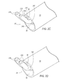
Turning to FIG. 2C , a further alternative arrangement of distal end 34 of shaft member 14 is shown. Shaft member 14 in FIG. 2C may be configured similar to that shown in FIGS. 2A-2B . Electrodes 216 include connection ends 241 that are disposed within electrode channels 240. Electrodes 216 differ from electrodes 16 and 116 in that electrodes 216 are configured as solid members, rather than having an internal lumen. Distal tips 246 of electrodes are angled away from aspiration lumen 36, similar to distal tips 46, 146.
Another embodiment of distal end 34 of shaft member 14 is shown is shown in FIG. 2D . Shaft member 14 in FIG. 2D may be configured generally the same as that shown in FIGS. 2A-2C . Electrodes 316 include connection ends 341 that are sealed within electrode channels 40, similar to that shown in FIGS. 2A-2B . Electrodes 316 are also configured similar to that that arrangement shown in FIG. 2C , in that electrodes 316 are configured as solid members, rather than having an internal lumen. Distal tips 346 of electrodes 316 are angled away from aspiration lumen 36, similar to distal tips 46, 146, and 246.
Irrigation is supplied by fluid lumen 38. In the configuration shown in FIG. 2D , fluid lumen 38 is required, if it is desired that surgical instrument 10 provides fluid. In one arrangement, fluid lumen 38 may be selected to have a predetermined diameter so as to be self-regulating at a desired flow rate.
A further alternative arrangement of distal end 34 of shaft member 14 is shown in FIGS. 2E-2F . Shaft member 14 in FIG. 2E may be configured to be generally the same as that shown in FIGS. 2A-2D . Electrodes 416 include connection ends 441 that are sealed within electrode channels 40, similar to that shown in FIGS. 2A-2B . Electrodes 416 may also be configured similar to that that arrangement shown in FIG. 2C , in that electrodes 416 may be configured as solid members, rather than having an internal lumen. However, it is understood that electrodes 416 may alternatively be configured with internal lumens, such as that shown in FIGS. 2A-2B and be provided with irrigation lumens positioned in either distal tips 446, similar to FIG. 2A or along the length of electrodes, as shown in FIG. 2B . Distal tips 446 of electrodes are angled away from aspiration lumen 36, similar to distal tips 46, 146, 246, 346. Further, in this exemplary arrangement, distal tips 446 of electrodes 416 are also splayed apart as best seen in FIG. 2F . This configuration defines a treatment passage 448 having a first treatment passage portion 448 a formed by a parallel arrangement of electrodes 416. A second treatment passage portion 448 b expands outwardly from first treatment passage portion 448 a and is defined by electrodes 416 that are angled away from one another. This configuration permits compression of blood vessels 450 (shown in phantom) while cauterization is occurring.
Irrigation is supplied is supplied by fluid lumen 38. In the configuration shown in FIG. 2D , fluid lumen 38 is required, if it is desired that surgical instrument 10 provides fluid. In one arrangement, fluid lumen 38 may be selected to have a predetermined diameter so as to be self-regulating at a desired flow rate or may be controlled from an external regulated source.
A further alternative arrangement of distal end 534 of shaft member 514 is shown in FIG. 2G . Distal end 534 is configured with an aspiration lumen 536, a fluid lumen 538, and electrode channels 540. Electrodes 516 are disposed within electrode channels 540.
Alternatively, electrodes 516 may be sealed within electrode channels, thereby omitting the irrigation annulus 540, similar to the configurations illustrated in FIGS. 2A-2B and 2D-2E . In such an arrangement, electrodes 516 may be configured with irrigation lumens, similar to that shown in FIG. 2A . Alternatively, irrigation may be supplied through fluid lumen 538.
Referring to FIGS. 2H-2K , a further embodiment of distal end 634 of shaft member 614 is illustrated. Distal end 634 of shaft member 614 is similar to distal end 534 of shaft member 514 in that distal end 634 is configured with an aspiration lumen 636, a fluid lumen 638, and electrode channels 640 that have a similar configuration as to that shown in FIG. 2G . Electrodes, 616 also have a similar configuration as to electrodes 516 and are disposed within electrode channels 640.
For example, aspiration lumen 636 is formed below electrode channels 640. Aspiration lumen 636 is defined by a bottom wall portion 643 and a bottom, surface 652 of a land area 645. As may be seen in FIGS. 2H and 2I , bottom wall portion 643 of aspiration lumen 636 may be beveled in a rearward direction. Undercuts 658 are in communication with bottom wall portion 643. Undercuts 658 cooperate with the beveled bottom wall portion 643 to prevent aspiration lumen 636 from being occluded during use.
Turning to FIGS. 2L-2M , a further alternative arrangement of a distal end 670 of a shaft member 672 is shown. Shaft member 672 in FIG. 2M may be configured generally the same as that shown in FIGS. 2H-2J , in that distal end 670 is configured with an aspiration lumen similar to that shown in FIG. 2I , a fluid lumen that is configured generally the same as that shown in FIG. 2I , and electrode channels that have a similar configuration as to that shown in FIG. 2H . Electrodes 674 are disposed within the electrode channels in a similar manner as sown in FIG. 2H .
However, in the arrangement shown in FIGS. 2L-2M , electrodes 674 are configured with generally opposing engagement surfaces 676 that cooperate to define a treatment pathway 680. Engagement surfaces 676 may be constructed to be generally planar. In one exemplary configuration, best seen in FIG. 2L , engagement surfaces 676 are oriented such that engagement surfaces 676 at tip members 678 are displaced further away from one another than engagement surfaces 676 adjacent a land area 678 of shaft member 672 such that a generally V-shaped treatment pathway 680 is created. This configuration allows for electrodes 674 to straddle a vessel, thereby focusing and delivering the energy of the electrodes 516 to the vessel to be coagulated, but not the surrounding tissues. Moreover, the V-shape treatment pathway 680 also serves to accommodate different sized vessels, represented in phantom in FIG. 2L . In one exemplary configuration, the distance between engagement surfaces 676 at tip member 678 is approximately 0.07 inches, while the distance between engagement surfaces 676 adjacent land member 678 is approximately 0.01.
As illustrated in FIG. 2M , electrodes 674 are configured as bent at 682. This configuration permits the electrodes 674 to be placed, when desired, parallel to a vessel to be coagulated, thereby minimizing the opportunity for damage to be caused by the electrodes 674 “digging into” to an underlying tissue substrate.
As discussed above, an aspiration lumen may be formed below electrode channels into which electrodes 674 are positioned. Aspiration, indicated by arrow A is directed into the aspiration lumen under electrodes 674. The aspiration lumen may be configured as shown in FIG. 2G or 2H and a bottom wall portion that defines the aspiration lumen may be beveled. While not shown, undercuts may also be provided.
A fluid lumen, similar to that which is shown in FIG. 2H may also be provided. A top wall portion that defines the fluid lumen may be beveled. This arrangement increases the field of view for a user, providing better visualization of distal tips 678 of electrodes 674 during use. The fluid lumen permits selective delivery of fluid represented by arrow F (as shown in FIG. 2M ) to the surgical field to facilitate and effectively manage the ability of a user to deliver any additional needed fluid to a surgical site in an in-line orientation. The ability to simultaneously provide irrigation, aspiration an coagulation in a common plane as a co-axial configuration whereby the irrigation channel is above the electrodes and the aspiration channel is below the electrodes allows the user to irrigate the surgical field sufficiently with a “flushing action” of the irrigant exiting the irrigation channel in the same plane as the electrodes while the surgeon accurately controls the quantity of fluid aspirated from the surgical field so as to provide a clear field of view of where the actual bleeding vessel is originating from. This provides the surgeon the ability to accurately and precisely deliver coagulation to the offending vessel without damage to collateral tissues due to blindly digging, probing and burning the collateral tissues in search of the offending vessel.
Referring to FIG. 2N , a further exemplary arrangement of a distal end 684 of handpiece 672 is illustrated. The arrangement in FIG. 2N is generally the same as that of FIGS. 2L and 2M , except that the land area 679′ has been slightly modified. Accordingly, identical elements have been given identical reference numbers as the arrangement shown in FIGS. 2L-2M .
The land area 679′ is positioned between a fluid lumen where fluid F is configured to exit from the distal end 684 of the handpiece 672′ and an aspiration lumen that is configured to aspirate A fluid from a surgical site. Formed within the land area 679′ are electrode channels 686 through which electrodes 678 protrude. Electrode channels 686 are sized to be larger than a diameter of the electrodes 678 such that electrode channels 686 may be used to deliver fluid therethrough as discussed above in connection with previous alternative arrangements, such as, for example, FIG. 2G-2H . The land area 679′ further differs from land area 679 in that is extends further away from the distal end 684 of the handpiece 672′, thereby enhancing visibility. In addition, a front face 688 may be angled so as to slope distally outward from a top edge 690 to a bottom edge 692. As may, be seen in FIG. 2N , bottom edge 692 is positioned distally of the top edge 690.
Referring to FIGS. 3A-3B , exemplary alternative options for a distal end of a shaft member are illustrated. More specifically, as illustrated in FIG. 3A , distal end 734 of a shaft member 714 is illustrated. Distal end 734 may be configured with a generally planar end face 733. Electrode openings 40 and aspiration lumen 36 extend proximally from end face 733. Fluid lumen 38 also extends proximally from end face 733. In the arrangement illustrated in FIG. 3A , fluid lumen 38 is positioned above aspiration lumen 36, but below and between electrode openings 40. Aspiration lumen 36 is contoured around fluid lumen 38. To reduce the profile of shaft member 714 and improve visibility of electrodes (not shown), a portion of shaft member 714 positioned above electrode openings 40 may be beveled to create a generally planar surface 715.
A sealing groove 86 is formed in the outer surface of outer sleeve 62. Sealing groove 86 is configured to receive a sealing member 87. Sealing member 87 serves to provide a seal between outer sleeve 62 and outer sleeve 64. An electrode opening 88 is formed through proximal end 77 inner sleeve. Electrode opening 88 permits a connection end of electrodes 16 to be joined to a connection port 90, as seen in FIGS. 6-7B . A proximal chamber 91 is formed within proximal end 77 of inner sleeve 62. A radially inward extending rib 92 separates proximal chamber 91 and vacuum chamber 82.
A second irrigation chamber 122 is provided between an outer distal surface of inner mounting member 94 and sealing member 103. Irrigation chamber 122 is in communication with one of openings 84 through inner sleeve 62, as well as an opening 123 that is formed within shaft member 14, between irrigation opening 65 and aspiration opening 66. Opening 123 is in communication with fluid lumen 38 and may be sized to provide a controlled flow rate of fluid through the fluid lumen 38.
Referring to FIG. 8 , control valve 28 is illustrated and will be explained. Control valve 28 comprises vent opening 26 and slidable sleeve 32. Vent opening 26 is in communication with vacuum chamber 82. In on exemplary configuration, vent opening 26 is configured with a teardrop shape, allowing the greatest amount of vacuum to be delivered when the entirety of the vent opening 26 is covered. However, slidable sleeve 32 is configured to be selectively moved to cover or uncover vent opening 26 to immediately vary aspiration being delivered through aspiration lumen 36. More specifically, in the configuration shown in FIG. 8 , when it is desired to have full aspiration, slidable sleeve 32 is moved distally to completely cover vent opening 26. A degree of vacuum will immediately be delivered as sleeve 32 advances over the widest portion of the teardrop shape (i.e., the bottom portion). As the slidable sleeve 32 approaches the tip of the teardrop (i.e., the top portion), fine application of vacuum may be applied.
As described above, slidable sleeve 32 may be provided with inner rib members (not shown) that are configured to frictionally engage receiving grooves 74 to retain slidable sleeve 32 to collar 67. When it is desired to reduce aspiration pressure, slidable sleeve 32 is moved in a proximal direction to at least partially expose vent opening 26, thereby venting vacuum chamber 82. When slidable sleeve 32 is moved so as to completely expose vent opening 26, there is no aspiration being delivered to aspiration lumen 36. This configuration is advantageous in that it permits a user to immediately release tissue while in use, as well as reduce aspiration as needed. Due to its position on handpiece 12, slidable sleeve 32 is easy to manipulate with a single hand from any orientation of the user gripping the device, also providing improved ease of use.
In one exemplary arrangement, vent opening 26 has a teardrop shape. This shape permits a controlled reduction of aspiration as slidable sleeve 32 moves proximally. However, it is understood that other shapes of vent opening 26 may be employed. It is also contemplated that other arrangements for operation of the slidable sleeve and vent opening may be utilized. Further examples will be discussed below.
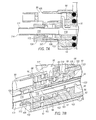
An alternative arrangement of surgical device 200 is shown in FIGS. 9-12 . FIG. 9A illustrates an exploded view of surgical device 200. FIG. 10A illustrates a cross-sectional view of surgical device 200. While the distal tip of surgical device 200 is similar to the arrangement shown in FIG. 2G , it is understood that any of the distal tip arrangements illustrated in FIGS. 2A-2N may be employed, including, but not limited to spacing of the electrodes, or the particular configurations of the electrode tips.
In one exemplary arrangement, the tear drop shape of vent opening 226 is oriented with the widest part of the vent opening 226 toward the proximal end 277 of sleeve 262. In this arrangement, the slidable sleeve 232 may be biased toward the proximal end 277 with a spring member 283, shown in phantom in FIG. 10A . With this configuration, the slidable sleeve 232 is biased toward the proximal end 277 such that, the surgical device 200 operation is biased toward no vacuum delivery. However, other exemplary configurations of the interaction of the slidable sleeve and vent opening are contemplated, and will be discussed in further detail below.
In one exemplary configuration, proximal end 277 of sleeve 262 includes an integrally formed hub member 263, allowing for ease of manufacture. However, it is understood that hub member 263 and sleeve 262 may be formed as separate elements without departing from the disclosure. Hub member 263 is generally hollow and includes fluid openings 284 for introduction of fluid into surgical device 200. In one exemplary arrangement, fluid openings 284 may be formed through a mounting plate 285 carried by hub member 263. A fluid connector (not shown) is configured to engage mounting plate 285 and cooperate with openings 284 to deliver fluid through shaft member 214.
In another exemplary arrangement (best seen in FIG. 13 ), mounting plate 285 is eliminated from hub 263′. Ports 288 that are connected to fluid openings 284 are formed through the hub 263′ to which fluid tubes 291 a and 291 b may be connected. In one exemplary arrangement, the fluid tubes 291 a and 291 b may be glued directly to the ports 288. In another exemplary arrangement, the ports 288 may be configured with upwardly extending hose barbs (not shown) to which fluid tubes 291 a and 291 b may be disposed over.
In one exemplary arrangement, hub member 263 defines a chamber 287 (see, FIG. 12 ) therein that is configured to receive an inner mounting member 294 (see FIG. 9A ). Inner mounting member 294 will be discussed in greater detail below. As seen in FIGS. 10A-B , Chamber 287 may be configured with a step 296 that engages with a radially extending edge 303 of inner mounting member 294. Hub member 263 may further define a lateral opening 295 (FIG. 12 ). In one exemplary configuration, an end flange 305 may be disposed on proximal end 277. In one exemplary configuration, end flange 305 includes extension members 306 disposed on either side of lateral opening 295. Extension members 306 may each include openings 307. The openings 307 are configured to receive suitable fluid tubing (such as that shown in FIG. 13 ) that mates with fluid openings 284.
Inner mounting member 294 is configured to be positioned in chamber 287 of hub member 263. Inner mounting member 294 includes a body member 297 which defines first and second sealing grooves 293 a, 293 b and a distal sleeve segment 298. An electrode opening 300 is formed through an outer surface of inner mounting member 294. Electrode opening 300 aligns with lateral opening 295 to provide a pathway for electrodes 216. In one exemplary arrangement, a stabilizing member 301 is configured to be received within electrode opening 300. In another exemplary arrangement, stabilizing member is integrally formed with the inner mounting member 294. Stabilizing member 301 includes mounting channels 302 that are configured to secure electrodes 216 within shaft member 214 and direct ends of electrodes 216 to a connection mount 290 formed on an end cap 305. Connection mount 290 is configured to receive a connection port (as shown, for example, in FIG. 13 ) to operatively connect electrodes 216 to an electrical source for energizing electrodes 216. A proximal end of electrodes 216 will be received within the connection port to facilitate delivery of energy.
Sealing members 309 and 310 are received within sealing grooves 293 a and 293 b, respectively, and provides a seal between inner mounting member 294 and sleeve 262 so as to provide a sealed fluid pathway for irrigation lumens disposed around or through electrodes 216, including irrigation lumens 44, 144, 240, 540, and 640. (see, e.g., FIG. 11 ). An additional sealing member 311 is positioned between a rib 292 and a distal end of inner mounting member 294. Sealing member 311 cooperates with sealing member 293 b to provide a fluid pathway that is in communication with fluid lumen 38. Rib 292 separates a flush chamber 326 (which is in communication with flush opening 266) and vacuum chamber 282.
A shaft mount 312 is received within inner mounting member 294. Shaft mount 312 is generally hollow. End cap 305 includes an aspiration mount 314 having an opening 316. The shaft mount 312 is disposed through opening 316. Shaft mount 312 is in fluid communication with proximal end 258 of shaft member 214, and in particular with aspiration lumen 36. Shaft mount 312 is configured to be connected to a suitable vacuum source. An outer surface of shaft mount 312 may include a mounting collar 317. Mounting collar 317 positions shaft mount 312 within inner mounting member 294, as well as allow for rotation of shaft mount 312 relative to end cap 305. A seal member 319 may be positioned around shaft mount 312, within a cavity 321 of end cap 305. Seal member 319 serves to direct aspiration to aspiration lumen 36. Area 323, adjacent to stabilizing member 301, is filled with adhesive (not shown) or other suitable material so ensure that aspiration is directed to aspiration lumen 36. Further, to isolate fluid delivery from aspiration, areas 325 and 327 are filled with adhesive on either side of a fluid channel 329 formed in inner mounting member 294 that is in communication with one of openings 284 and irrigation opening 265, similar to what is shown and described in FIG. 7B .
In one exemplary arrangement, vent opening 226 has a teardrop shape. This shape permits a controlled reduction of aspiration as slidable sleeve 232 moves proximally. However, it is understood that other shapes of vent opening 226 may be employed.
An alternative arrangement for control valve 228′ is shown in FIG. 13 . Control valve 228′ also comprises slidable sleeve 232 and vent opening 226. In this arrangement, however, slidable sleeve 232 is either biased toward distal end 276 of sleeve 262 with a spring mechanism (such as that shown in phantom in FIG. 10A ) or permitted to freely float over sleeve 262. When permitted to freely float, as surgical device 200′ is used distal end 276 will be oriented in a downward direction, slidable sleeve 262 will automatically slide toward the distal end 276. This action will completely uncover vent opening 226, thereby ensuring that no vacuum is delivered.
However, when vacuum is desired to be delivered to the distal end 276, the slidable sleeve 232 is moved in a proximal direction. In the control valve 228′, the vent opening 226 is oriented so that the widest part of the teardrop shape is oriented toward the distal end 276 such that as slidable sleeve 232 is moved over the vent opening 226, the widest part will be covered first.
As outer member 264 is not required, a stiffening member 215 may be provided. In one exemplary arrangement, stiffening member 215 may extend substantially the length of the shaft member 214. More specifically, stiffening member 215 may be disposed in fluid lumen 38, as illustrated in FIG. 11 . Stiffening member 215 assists in enabling the shaft member 214 to hold its shape.
Referring to FIGS. 9A and 9B , the proximal end 258 of shaft member 214 is configured with a land area 320 having grooves 322 formed in a top surface thereof. Grooves 322 extend into an end face 324 of shaft member 214 and join fluid openings 44 (or 144, 544, 644). Electrodes 216 are configured to be received within fluid openings 44.
In operation, fluid is delivered into opening 284 (via a fluid tubing connected thereto) and communicated into fluid channel 329 so as to direct irrigation to electrode channels 40. In this manner, fluid exits around electrodes 16, 116, 216, 316, 416, 516, 616, 674 during operation, so as to provide metered irrigation to the surgical site, thereby creating a “wet field”. Fluid may further be selectively provided to the surgical field through the other opening 284 (via a fluid tubing connected thereto). The other opening 284 is in communication with a flush chamber 326. A flush opening 266 formed in fluid lumen 38 is arranged within the flush chamber 326. In this manner, additional fluid may be optionally delivered through fluid lumen 38 to power flush a surgical site, thereby enabling clearing of surgical site, as well as assisting in locating the source of bleeding.
Referring to FIG. 13 , as discussed above, proximal end 277′ of sleeve 262′ includes a hub 263′, which include fluid openings 288. Fluid tubes 291 a and 291 b may be directly fixedly secured to fluid openings 288. As is shown in FIG. 10B , one of fluid tubes 291 a is operatively connected to flush chamber 326 via flush opening 266, while the other of fluid tubes 291 b is operatively connected to fluid channel 329 so as to direct irrigation to fluid lumen 38.
An end cap 305′ slides over a proximal end of hub 263′ until end cap 305′ is positioned adjacent fluid openings 288. End cap 305′ is configured with an outer sleeve portion 402 that is generally the same diameter as sleeve 262′. Instead of laterally spaced extension members 306 on hub 263, end cap 305′ is provided with a fluid retention member 404. Fluid retention member 404 includes an opening therethrough 406 that is sized to receive fluid tubes 291 a, and 291 b therein. An opening is formed in the proximal end of end cap 305′, similar to that depicted in FIG. 10B . The opening is configured to be connected to an aspiration tubing 408 to deliver vacuum to vacuum chamber 282 via aspiration lumen 36.
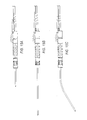
A further alternative arrangement for a bipolar surgical device 500 is shown in FIGS. 14A-14B . Bipolar surgical device 500 is similar to devices 10 and 200 in that it includes a handpiece 512, a shaft member 514 extending distally from handpiece 512 and electrodes 16, 116, 216, 316, 416, 516, 616, 674 (as best seen in FIGS. 2A-2N ) extending distally from shaft member 514. Operatively connected to handpiece 512 is an aspiration line 518 and a cautery supply cable 522.
In this embodiment, however, a single fluid delivery line 520 is operatively connected to the handpiece 512. Fluid delivery line 520 has a distal end 522 that is secured to a fluid opening 584 and a proximal end 524 that is connected to a connector element 526. Connector element 524 includes two inlets 528 a and 528 b and a single outlet 530. Proximal end 524 of fluid delivery line 520 is fixedly attached to outlet 530.
Connected to inlet 528 a is fluid line 591 a. An opposite end of fluid line 591 a may be connected to a one-way check valve 532. A second fluid line 593 a is connected to check valve 532. Second fluid line 593 a terminates in a fitting 534. Fitting 534 is configured to be connected to a fluid source. In operation, once a fluid source is connected to the fitting 534, fluid is delivered through check valve 532, into fluid line 591 a, through connector 526 and into fluid delivery line 520. Fluid is then fed into electrode channels 40, 240 so as to exit shaft member 514 adjacent the electrodes tips. This configuration allows continuous delivery or irrigation of fluid at a surgical site so as to create a wet surgical field. Because the check valve 532 is a one-way check valve, fluid is prevented from back flushing through the check valve 532.
Connected to inlet 528 b is another fluid line 591 b. Fluid line 591 b terminates in a fitting 536. Fitting 536 is also configured to be connected to a secondary fluid source. When fitting 536 is connected to the secondary fluid source, fluid is delivered through fluid line 591 b, through connector 526 and into fluid delivery line 520. Fluid is then fed into electrode channels 40, 240 so as to exit shaft member 214 adjacent the electrode tips. However, the secondary fluid source is configured to selectively deliver a burst of fluid, so as to power flush the surgical site. Power flushing the surgical site in operation is beneficial to clear the surgical field and locate bleeding sources in the surgical field.
The arrangement in FIGS. 14A and 14B differs from the arrangement shown in FIGS. 10A and 10B in that only a lumen is provided in shaft member 514 of surgical device 500 as opposed to fluid lumen 38 and electrode channels 40 provided in shaft member 214. More specifically, in the arrangement of surgical device 500 two sources of irrigation are delivered through electrode channels 40 to provided constant irrigation at the surgical site, as well as provide a selective power flush through the same electrode channels 40. This configuration thereby allows a reduced diameter shaft 514, thereby providing improved visualization capability at the surgical site.
It will be appreciated that the surgical instrument and methods described herein have broad applications. The foregoing embodiments were chosen and described in order to illustrate principles of the methods and apparatuses as well as some practical applications. The preceding description enables others skilled in the art to utilize methods and apparatuses in various embodiments and with various modifications as are suited to the particular use contemplated. In accordance with the provisions of the patent statutes, the principles and modes of operation of this disclosure have been explained and illustrated in exemplary embodiments.
It is intended that the scope of the present methods and apparatuses be defined by the following claims. However, it must be understood that this disclosure may be practiced otherwise than is specifically explained and illustrated without departing from its spirit or scope. It should be understood by those skilled in the art that various alternatives to the embodiments described herein may be employed in practicing the claims without departing from the spirit and scope as defined in the following claims. The scope of the disclosure should be determined, not with reference to the above description, but should instead be determined with reference to the appended claims, along with the full scope of equivalents to which such claims are entitled. It is anticipated and intended that future developments will occur in the arts discussed herein, and that the disclosed systems and methods will be incorporated into such future examples. Furthermore, all terms used in the claims are intended to be given their broadest reasonable constructions and their ordinary meanings as understood by those skilled in the art unless an explicit indication to the contrary is made herein. In particular, use of the singular articles such as “a,” “the,” “said,” etc. should be read to recite one or more of the indicated elements unless a claim recites an explicit limitation to the contrary. It is intended that the following claims define the scope of the invention and that the method and apparatus within the scope of these claims and their equivalents be covered thereby. In sum, it should be understood that the invention is capable of modification and variation and is limited only by the following claims.
Claims (17)
1. A surgical device, comprising:
a sleeve member;
a shaft member extending distally from the sleeve member, wherein the shaft member includes a pair of electrode channels comprising a first electrode channel and a second electrode channel, the pair of electrode channels defining a first opening and a second opening at a distal end of the shaft member, wherein the first and second electrode channels are positioned adjacent to one another;
a pair of electrodes comprising a first electrode and a second electrode, the pair of electrodes configured to deliver energy, wherein the first electrode is disposed in the first electrode channel and the second electrode is disposed in the second electrode channel such that distal ends of each of the first and second electrodes are arranged to protrude from the distal end of the shaft member;
wherein each of the first and second electrode channels are both configured with a diameter that is larger than a diameter of the each of the first and second electrodes so as to form a first irrigation annulus between the first electrode and an inner surface of the first electrode channel, and a second irrigation annulus between the second electrode and an inner surface of the second electrode channel; and
wherein the sleeve member further comprises a vacuum chamber therein, wherein the shaft member extends through the vacuum chamber and the shaft member includes a vacuum opening that is in communication with the vacuum chamber to deliver vacuum from the vacuum chamber through an aspiration lumen of the shaft to at least one aspiration lumen opening at the distal end of the shaft member.
2. The surgical device of claim 1 , further comprising a fluid lumen opening at the distal end of the shaft member.
3. The surgical device of claim 2 , wherein the fluid lumen opening is positioned above the first and second electrode channels.
4. The surgical device of claim 3 , wherein the aspiration lumen opening is disposed opposite the fluid lumen, with the first electrode opening and the second electrode opening being arranged between the fluid and aspiration lumens.
5. The surgical device of claim 1 , wherein the first and second electrodes each include a generally planar opposing engagement surface.
6. The surgical device of claim 5 , wherein the generally planar engagement surfaces of the first and second electrodes taper outwardly from the distal end of the shaft to the distal ends of the first and second electrodes define a generally V-shape treatment pathway.
7. The surgical device of claim 1 , further including a vacuum control valve that is in communication with the vacuum chamber to selectively vary aspiration pressure delivered through shaft member.
8. The surgical device of claim 7 , wherein the vacuum control valve comprises a vent aperture in the sleeve and a selectively slidable member that is configured to selectively cover and uncover at least portions of the vent aperture, which is in communication with the vacuum chamber, to selectively control the aspiration pressure.
9. The surgical device of claim 8 , wherein the vent aperture is tear drop shaped, with the largest portion of the vent aperture being oriented toward the distal end of the sleeve member.
10. The surgical device of claim 1 , further comprising a flush chamber disposed in the sleeve member, wherein the shaft member extends through the flush chamber and wherein the shaft member includes a flush opening that is in communication with a fluid lumen extending through the shaft member.
11. The surgical device of claim 10 , further comprising a fluid channel disposed in the sleeve member, wherein the fluid channel is in communication with the first and second electrode channels, and wherein the first and second electrode channels are both in communication with a fluid chamber.
12. The surgical device of claim 1 , further comprising a shaft mount disposed at a proximal end of the sleeve member, wherein the shaft mount is in fluid communication with the aspiration lumen of the shaft member and is configured to be connected to a vacuum source.
13. The surgical device of claim 12 , further comprising a mounting collar disposed about the shaft mount, wherein the mounting collar is arranged within a cavity of an end cap attached to the proximal end of the sleeve member, and is configured to permit the shaft mount to rotate with respect to the sleeve member.
14. The surgical device of claim 13 , wherein the end cap further comprises a connection mount configured to receive a connection port to operatively connect the first and second electrodes to an electrical source for energizing the first and second electrodes.
15. The surgical device of claim 1 , further comprising a fluid delivery line in fluid communication with the first and second electrode channels.
16. The surgical device of claim 15 , further comprising a connector element having a first inlet, a second inlet, and an outlet, wherein the fluid delivery line is connected to the outlet, wherein a first fluid line and a second fluid line connected to the first inlet and the second inlet, respectively, and wherein the first fluid line is operatively connectable to a first fluid source and the second fluid line is operatively connectable to a second fluid source.
17. The surgical device of claim 16 , further comprising a check valve operatively connected to the first fluid line.
Priority Applications (14)
| Application Number | Priority Date | Filing Date | Title |
|---|---|---|---|
| US13/975,494 US9775672B2 (en) | 2012-08-31 | 2013-08-26 | Bi-polar surgical instrument |
| CA2880084A CA2880084A1 (en) | 2012-08-31 | 2013-08-27 | Bi-polar surgical instrument |
| KR1020157005726A KR20150050558A (en) | 2012-08-31 | 2013-08-27 | Bi-polar surgical instrument |
| AU2013309059A AU2013309059A1 (en) | 2012-08-31 | 2013-08-27 | Bi-polar surgical instrument |
| PCT/US2013/056765 WO2014035944A1 (en) | 2012-08-31 | 2013-08-27 | Bi-polar surgical instrument |
| EP19204025.1A EP3616638B1 (en) | 2012-08-31 | 2013-08-27 | Bi-polar surgical instrument |
| EP13759931.2A EP2890320B1 (en) | 2012-08-31 | 2013-08-27 | Bi-polar surgical instrument |
| JP2015529920A JP6408992B2 (en) | 2012-08-31 | 2013-08-27 | Bipolar surgical instrument |
| BR112015004184A BR112015004184A2 (en) | 2012-08-31 | 2013-08-27 | surgical device |
| US14/639,887 US10383680B2 (en) | 2012-08-31 | 2015-03-05 | Bi-polar surgical instrument |
| JP2018176743A JP6795563B2 (en) | 2012-08-31 | 2018-09-21 | Bipolar surgical instruments |
| JP2019185195A JP7015065B2 (en) | 2012-08-31 | 2019-10-08 | Bipolar surgical instrument |
| US16/662,814 US20200121384A1 (en) | 2012-08-31 | 2019-10-24 | Bi-polar surgical instrument |
| JP2022004197A JP2022046788A (en) | 2012-08-31 | 2022-01-14 | Bipolar surgical instrument |
Applications Claiming Priority (2)
| Application Number | Priority Date | Filing Date | Title |
|---|---|---|---|
| US201261695411P | 2012-08-31 | 2012-08-31 | |
| US13/975,494 US9775672B2 (en) | 2012-08-31 | 2013-08-26 | Bi-polar surgical instrument |
Related Child Applications (2)
| Application Number | Title | Priority Date | Filing Date |
|---|---|---|---|
| US13/975,486 Continuation-In-Part US9782220B2 (en) | 2012-08-31 | 2013-08-26 | Bi-polar surgical instrument |
| US13/975,486 Continuation US9782220B2 (en) | 2012-08-31 | 2013-08-26 | Bi-polar surgical instrument |
Publications (2)
| Publication Number | Publication Date |
|---|---|
| US20140066930A1 US20140066930A1 (en) | 2014-03-06 |
| US9775672B2 true US9775672B2 (en) | 2017-10-03 |
Family
ID=50188496
Family Applications (3)
| Application Number | Title | Priority Date | Filing Date |
|---|---|---|---|
| US13/975,494 Active 2035-10-29 US9775672B2 (en) | 2012-08-31 | 2013-08-26 | Bi-polar surgical instrument |
| US13/975,486 Active 2035-12-30 US9782220B2 (en) | 2012-08-31 | 2013-08-26 | Bi-polar surgical instrument |
| US15/727,994 Pending US20180092685A1 (en) | 2012-08-31 | 2017-10-09 | Bi-polar surgical instrument |
Family Applications After (2)
| Application Number | Title | Priority Date | Filing Date |
|---|---|---|---|
| US13/975,486 Active 2035-12-30 US9782220B2 (en) | 2012-08-31 | 2013-08-26 | Bi-polar surgical instrument |
| US15/727,994 Pending US20180092685A1 (en) | 2012-08-31 | 2017-10-09 | Bi-polar surgical instrument |
Country Status (8)
| Country | Link |
|---|---|
| US (3) | US9775672B2 (en) |
| EP (2) | EP2890320B1 (en) |
| JP (4) | JP6408992B2 (en) |
| KR (1) | KR20150050558A (en) |
| AU (1) | AU2013309059A1 (en) |
| BR (1) | BR112015004184A2 (en) |
| CA (1) | CA2880084A1 (en) |
| WO (1) | WO2014035944A1 (en) |
Families Citing this family (24)
| Publication number | Priority date | Publication date | Assignee | Title |
|---|---|---|---|---|
| GB2480498A (en) | 2010-05-21 | 2011-11-23 | Ethicon Endo Surgery Inc | Medical device comprising RF circuitry |
| JP6234932B2 (en) | 2011-10-24 | 2017-11-22 | エシコン・エンド−サージェリィ・インコーポレイテッドEthicon Endo−Surgery,Inc. | Medical instruments |
| US11547446B2 (en) | 2014-01-13 | 2023-01-10 | Trice Medical, Inc. | Fully integrated, disposable tissue visualization device |
| US20150335376A1 (en) * | 2014-05-21 | 2015-11-26 | Covidien Lp | Multipurpose electrosurgical instrument with telescoping aspiration cannula |
| US10159524B2 (en) | 2014-12-22 | 2018-12-25 | Ethicon Llc | High power battery powered RF amplifier topology |
| US10959771B2 (en) | 2015-10-16 | 2021-03-30 | Ethicon Llc | Suction and irrigation sealing grasper |
| US10959806B2 (en) | 2015-12-30 | 2021-03-30 | Ethicon Llc | Energized medical device with reusable handle |
| CN109152584B (en) | 2016-03-17 | 2022-03-04 | 特里斯医疗有限公司 | Clot drainage and visualization devices and methods of use |
| US10987156B2 (en) | 2016-04-29 | 2021-04-27 | Ethicon Llc | Electrosurgical instrument with electrically conductive gap setting member and electrically insulative tissue engaging members |
| US10856934B2 (en) | 2016-04-29 | 2020-12-08 | Ethicon Llc | Electrosurgical instrument with electrically conductive gap setting and tissue engaging members |
| US10751117B2 (en) | 2016-09-23 | 2020-08-25 | Ethicon Llc | Electrosurgical instrument with fluid diverter |
| IT201600096420A1 (en) * | 2016-09-26 | 2018-03-26 | Kylix S R L | ELECTROSURGICAL DEVICE |
| US11033325B2 (en) | 2017-02-16 | 2021-06-15 | Cilag Gmbh International | Electrosurgical instrument with telescoping suction port and debris cleaner |
| US10799284B2 (en) | 2017-03-15 | 2020-10-13 | Ethicon Llc | Electrosurgical instrument with textured jaws |
| US11497546B2 (en) | 2017-03-31 | 2022-11-15 | Cilag Gmbh International | Area ratios of patterned coatings on RF electrodes to reduce sticking |
| US10603117B2 (en) | 2017-06-28 | 2020-03-31 | Ethicon Llc | Articulation state detection mechanisms |
| US11413087B2 (en) * | 2017-08-31 | 2022-08-16 | Cilag Gmbh International | End effector for electrosurgical instrument with irrigation |
| US11033323B2 (en) | 2017-09-29 | 2021-06-15 | Cilag Gmbh International | Systems and methods for managing fluid and suction in electrosurgical systems |
| US11490951B2 (en) * | 2017-09-29 | 2022-11-08 | Cilag Gmbh International | Saline contact with electrodes |
| US11484358B2 (en) | 2017-09-29 | 2022-11-01 | Cilag Gmbh International | Flexible electrosurgical instrument |
| US20190099209A1 (en) * | 2017-09-29 | 2019-04-04 | Ethicon Llc | Bipolar electrode saline linked closed loop modulated vacuum system |
| US11090101B2 (en) * | 2018-05-02 | 2021-08-17 | Medtronic Cryocath Lp | Soft balloon device and system |
| US11957342B2 (en) | 2021-11-01 | 2024-04-16 | Cilag Gmbh International | Devices, systems, and methods for detecting tissue and foreign objects during a surgical operation |
| CN115137468B (en) * | 2022-07-13 | 2022-11-25 | 海杰亚(北京)医疗器械有限公司 | Non-vacuum fluid transfer device and ablation needle system |
Citations (15)
| Publication number | Priority date | Publication date | Assignee | Title |
|---|---|---|---|---|
| US4590934A (en) | 1983-05-18 | 1986-05-27 | Jerry L. Malis | Bipolar cutter/coagulator |
| US5318563A (en) | 1992-06-04 | 1994-06-07 | Valley Forge Scientific Corporation | Bipolar RF generator |
| US5571100A (en) * | 1993-11-01 | 1996-11-05 | Gyrus Medical Limited | Electrosurgical apparatus |
| US5899884A (en) | 1997-01-17 | 1999-05-04 | Stryker Corporation | Suction regulator |
| US20010014806A1 (en) * | 1999-05-03 | 2001-08-16 | Ellman Alan G. | Electrosurgical handpiece for treating tissue |
| US6379351B1 (en) * | 1997-08-27 | 2002-04-30 | Arthrocare Corporation | Electrosurgical method for the removal of pacemaker leads |
| US20030216690A1 (en) * | 2002-05-15 | 2003-11-20 | Foley Kevin T. | Surgical suction regulator valve |
| US6730081B1 (en) | 1991-10-18 | 2004-05-04 | Ashvin H. Desai | Endoscopic surgical instrument |
| EP1795139A1 (en) | 2005-12-12 | 2007-06-13 | Sherwood Services AG | Laparoscopic apparatus for performing electrosurgical procedures |
| US7645277B2 (en) | 2000-09-22 | 2010-01-12 | Salient Surgical Technologies, Inc. | Fluid-assisted medical device |
| US20110022047A1 (en) | 2009-07-23 | 2011-01-27 | Tyco Healthcare Group Lp | Active Cooling System and Apparatus for Controlling Temperature of a Fluid used During Treatment of Biological Tissue |
| US20110178515A1 (en) | 2010-01-15 | 2011-07-21 | Bloom Eliot F | Electrosurgical Devices, Electrosurgical Unit and Methods of Use Thereof |
| US20130066317A1 (en) | 2011-09-08 | 2013-03-14 | Arthrocare Corporation | Plasma bipolar forceps |
| WO2013038042A1 (en) | 2011-09-14 | 2013-03-21 | Universidad Politécnica De Valencia | Bipolar electrosurgical device and method for cauterizing and cutting biological tissue |
| US20130331833A1 (en) | 2012-06-12 | 2013-12-12 | Medtronic Advanced Energy Llc | Debridement device and method |
Family Cites Families (10)
| Publication number | Priority date | Publication date | Assignee | Title |
|---|---|---|---|---|
| US5456689A (en) * | 1993-10-13 | 1995-10-10 | Arnold J. Kresch | Method and device for tissue resection |
| JP3807783B2 (en) * | 1996-05-31 | 2006-08-09 | 株式会社ニデック | Ophthalmic ultrasound surgery device |
| CA2216455C (en) * | 1996-10-04 | 2006-12-12 | Jeffrey J. Blewett | Apparatus for thermal treatment of tissue |
| JPH10127658A (en) * | 1996-10-28 | 1998-05-19 | Olympus Optical Co Ltd | Bipolar coagulation element |
| US5873877A (en) * | 1997-04-11 | 1999-02-23 | Vidamed, Inc. | Medical probe device with transparent distal extremity |
| JP4157183B2 (en) * | 1998-02-17 | 2008-09-24 | オリンパス株式会社 | Endoscopic treatment tool |
| JP2002028166A (en) * | 2000-07-18 | 2002-01-29 | Olympus Optical Co Ltd | Treatment device for nasal cavity |
| EP1363700A4 (en) * | 2001-01-11 | 2005-11-09 | Rita Medical Systems Inc | Bone-treatment instrument and method |
| US20050245923A1 (en) * | 2004-04-29 | 2005-11-03 | Medtronic, Inc. | Biopolar virtual electrode for transurethral needle ablation |
| US20160015451A1 (en) * | 2009-09-22 | 2016-01-21 | Mederi Therapeutics, Inc. | Systems and methods for treating tissue with radiofrequency energy |
-
2013
- 2013-08-26 US US13/975,494 patent/US9775672B2/en active Active
- 2013-08-26 US US13/975,486 patent/US9782220B2/en active Active
- 2013-08-27 AU AU2013309059A patent/AU2013309059A1/en not_active Abandoned
- 2013-08-27 KR KR1020157005726A patent/KR20150050558A/en not_active Application Discontinuation
- 2013-08-27 JP JP2015529920A patent/JP6408992B2/en active Active
- 2013-08-27 EP EP13759931.2A patent/EP2890320B1/en active Active
- 2013-08-27 CA CA2880084A patent/CA2880084A1/en not_active Abandoned
- 2013-08-27 BR BR112015004184A patent/BR112015004184A2/en not_active IP Right Cessation
- 2013-08-27 WO PCT/US2013/056765 patent/WO2014035944A1/en unknown
- 2013-08-27 EP EP19204025.1A patent/EP3616638B1/en active Active
-
2017
- 2017-10-09 US US15/727,994 patent/US20180092685A1/en active Pending
-
2018
- 2018-09-21 JP JP2018176743A patent/JP6795563B2/en active Active
-
2019
- 2019-10-08 JP JP2019185195A patent/JP7015065B2/en active Active
-
2022
- 2022-01-14 JP JP2022004197A patent/JP2022046788A/en active Pending
Patent Citations (16)
| Publication number | Priority date | Publication date | Assignee | Title |
|---|---|---|---|---|
| US4590934A (en) | 1983-05-18 | 1986-05-27 | Jerry L. Malis | Bipolar cutter/coagulator |
| US6730081B1 (en) | 1991-10-18 | 2004-05-04 | Ashvin H. Desai | Endoscopic surgical instrument |
| US5318563A (en) | 1992-06-04 | 1994-06-07 | Valley Forge Scientific Corporation | Bipolar RF generator |
| US5571100A (en) * | 1993-11-01 | 1996-11-05 | Gyrus Medical Limited | Electrosurgical apparatus |
| US5571100B1 (en) * | 1993-11-01 | 1998-01-06 | Gyrus Medical Ltd | Electrosurgical apparatus |
| US5899884A (en) | 1997-01-17 | 1999-05-04 | Stryker Corporation | Suction regulator |
| US6379351B1 (en) * | 1997-08-27 | 2002-04-30 | Arthrocare Corporation | Electrosurgical method for the removal of pacemaker leads |
| US20010014806A1 (en) * | 1999-05-03 | 2001-08-16 | Ellman Alan G. | Electrosurgical handpiece for treating tissue |
| US7645277B2 (en) | 2000-09-22 | 2010-01-12 | Salient Surgical Technologies, Inc. | Fluid-assisted medical device |
| US20030216690A1 (en) * | 2002-05-15 | 2003-11-20 | Foley Kevin T. | Surgical suction regulator valve |
| EP1795139A1 (en) | 2005-12-12 | 2007-06-13 | Sherwood Services AG | Laparoscopic apparatus for performing electrosurgical procedures |
| US20110022047A1 (en) | 2009-07-23 | 2011-01-27 | Tyco Healthcare Group Lp | Active Cooling System and Apparatus for Controlling Temperature of a Fluid used During Treatment of Biological Tissue |
| US20110178515A1 (en) | 2010-01-15 | 2011-07-21 | Bloom Eliot F | Electrosurgical Devices, Electrosurgical Unit and Methods of Use Thereof |
| US20130066317A1 (en) | 2011-09-08 | 2013-03-14 | Arthrocare Corporation | Plasma bipolar forceps |
| WO2013038042A1 (en) | 2011-09-14 | 2013-03-21 | Universidad Politécnica De Valencia | Bipolar electrosurgical device and method for cauterizing and cutting biological tissue |
| US20130331833A1 (en) | 2012-06-12 | 2013-12-12 | Medtronic Advanced Energy Llc | Debridement device and method |
Non-Patent Citations (13)
| Title |
|---|
| Donzelli et al. Otolaryngology-Head and Neck Surgery Sep. 1998, vol. 119, No. 3, p. 153-158, "Thermoprotective mechanisms of irrifation during bipolar cautery." |
| Donzelli et al. Otolaryngology—Head and Neck Surgery Sep. 1998, vol. 119, No. 3, p. 153-158, "Thermoprotective mechanisms of irrifation during bipolar cautery." |
| Dujovny et al. Plastic and Reconstructive Surgery Nov. 1975, vol. 56, No. 5, p. 585-587, "Bipolar Jeweler's Forcepts With Automatic Irrigation, for Coagulation in Microsurgery." |
| King et al. J. Neurosurg. Aug. 1972, vol. 37, p. 246-247, "Self-irrigating bipolar diathermy forceps, Technical Note." |
| Lantis et al. Journal of Laparoendoscopic and advanced surgical techniques 1998, vol. 8, No. 6, p. 381-396, "Comparison of Coagulation Modalities in Surgery." |
| Malis., Operative Neurosurgery Feb. 2006, vol. 58, p. ONS1-ONS12, "Electrosurgery and Bipolar Technology." |
| Nakagawa et al. Circulation 1995, vol. 91, p. 2264-2273, "Comparison of in Vivo Tissue Temperature Profile and Lesion Geometry for Radiofrequency Ablation With a Saline-Irrigated Electrode Versus Temperature Control in a Canine Thigh Muscle Preparation." |
| O'Connor et al. Surgery Apr. 1996, vol. 119, No. 4, p. 390-396, "William T. Bovie and electrosurgery." |
| PCT International Search Report and Written Opinion dated Dec. 12, 2013 for PCT/US2013/056765. |
| Sakatani et al. J. Neurosurg 1995, vol. 82, p. 669-671, "Isotonic mannitol and the prevention of local heat generation and tissue adherence to bipolar diathermy forceps tips during electrical coagulation, Technical Note." |
| Scarff., Surg. Neufol. May 1974, vol. 2, p. 213, "A New Bipolar Suction-Cautery Forceps for Micro-Neurosurgical Use." |
| Sharma et al. Indian J. Plast. Surg, Jul.-Dec. 2005. vol. 41, Issue 2, p. 162-166, "Irrigation-coupled bipolar cautery unit: A practical, economical, and simple version." |
| Topp et al. Annals of Surgery Apr. 2004, vol. 239, No. 4, p. 518-527, "Saline-Linked Surface Radiofrequency Ablation Factors Affecting Steam Popping and Depth of Injury in the Pig Liver." |
Also Published As
| Publication number | Publication date |
|---|---|
| AU2013309059A1 (en) | 2015-02-12 |
| JP2015526248A (en) | 2015-09-10 |
| JP6795563B2 (en) | 2020-12-02 |
| US20180092685A1 (en) | 2018-04-05 |
| JP6408992B2 (en) | 2018-10-24 |
| BR112015004184A2 (en) | 2017-07-04 |
| WO2014035944A1 (en) | 2014-03-06 |
| EP3616638A1 (en) | 2020-03-04 |
| US20140066930A1 (en) | 2014-03-06 |
| US9782220B2 (en) | 2017-10-10 |
| US20140066929A1 (en) | 2014-03-06 |
| JP2022046788A (en) | 2022-03-23 |
| CA2880084A1 (en) | 2014-03-06 |
| JP7015065B2 (en) | 2022-02-02 |
| KR20150050558A (en) | 2015-05-08 |
| EP2890320A1 (en) | 2015-07-08 |
| JP2019022690A (en) | 2019-02-14 |
| EP3616638B1 (en) | 2023-11-15 |
| AU2013309059A2 (en) | 2015-03-12 |
| JP2020018884A (en) | 2020-02-06 |
| EP2890320B1 (en) | 2019-11-20 |
Similar Documents
| Publication | Publication Date | Title |
|---|---|---|
| US20180092685A1 (en) | Bi-polar surgical instrument | |
| US10383680B2 (en) | Bi-polar surgical instrument | |
| US6282442B1 (en) | Multi-fit suction irrigation hand piece | |
| EP2438876B1 (en) | Electrosurgical Cobb Elevator Instrument | |
| US7621911B2 (en) | Disposable/removable tubing set for use with an electrosurgical instrument | |
| US11071579B2 (en) | Bipolar cutting and hemostasis blade system | |
| US8992520B2 (en) | Dual-mode electrosurgical devices and electrosurgical methods using same | |
| AU2006252010A1 (en) | Laparoscopic apparatus for performing electrosurgical procedures | |
| US20060287651A1 (en) | Four function microsurgery instrument | |
| US10617803B2 (en) | Aspirating cautery forceps | |
| WO2016029201A1 (en) | Attachment for electrosurgical system | |
| US20200121384A1 (en) | Bi-polar surgical instrument | |
| US20070119986A1 (en) | Surgical apparatus for separating a biological structure with the aid of a liquid jet | |
| US11857242B2 (en) | Attachment for electrosurgical system | |
| US7951146B2 (en) | RF intervertebral electrosurgical probe | |
| US20220401261A1 (en) | Ophthalmological surgery microsurgery instruments and methods of use in pars plana vitrectomy for increasing surgical precision and reducing vitreoretinal instrument insertions and removals and related trauma | |
| US20230149212A1 (en) | Surgical apparatus for performing microsurgery including a multifunctional intraocular pick/dissector | |
| JPH1147152A (en) | Surgical tweezers |
Legal Events
| Date | Code | Title | Description |
|---|---|---|---|
| AS | Assignment |
Owner name: NICO CORPORATION, INDIANA Free format text: ASSIGNMENT OF ASSIGNORS INTEREST;ASSIGNORS:MARK, JOSEPH L.;DOUGHERTY, BRIAN;REEL/FRAME:035152/0956 Effective date: 20131025 |
|
| STCF | Information on status: patent grant |
Free format text: PATENTED CASE |
|
| MAFP | Maintenance fee payment |
Free format text: PAYMENT OF MAINTENANCE FEE, 4TH YEAR, LARGE ENTITY (ORIGINAL EVENT CODE: M1551); ENTITY STATUS OF PATENT OWNER: LARGE ENTITY Year of fee payment: 4 |