US9786829B2 - Thermocouple device - Google Patents
Thermocouple device Download PDFInfo
- Publication number
- US9786829B2 US9786829B2 US13/051,748 US201113051748A US9786829B2 US 9786829 B2 US9786829 B2 US 9786829B2 US 201113051748 A US201113051748 A US 201113051748A US 9786829 B2 US9786829 B2 US 9786829B2
- Authority
- US
- United States
- Prior art keywords
- thermocouple
- printed
- elements
- electrical connectors
- metal containing
- Prior art date
- Legal status (The legal status is an assumption and is not a legal conclusion. Google has not performed a legal analysis and makes no representation as to the accuracy of the status listed.)
- Active
Links
- GDOPTJXRTPNYNR-UHFFFAOYSA-N CC1CCCC1 Chemical compound CC1CCCC1 GDOPTJXRTPNYNR-UHFFFAOYSA-N 0.000 description 1
Images


Classifications
-
- H01L35/32—
-
- G01K13/002—
-
- G—PHYSICS
- G01—MEASURING; TESTING
- G01K—MEASURING TEMPERATURE; MEASURING QUANTITY OF HEAT; THERMALLY-SENSITIVE ELEMENTS NOT OTHERWISE PROVIDED FOR
- G01K13/00—Thermometers specially adapted for specific purposes
- G01K13/20—Clinical contact thermometers for use with humans or animals
-
- G—PHYSICS
- G01—MEASURING; TESTING
- G01K—MEASURING TEMPERATURE; MEASURING QUANTITY OF HEAT; THERMALLY-SENSITIVE ELEMENTS NOT OTHERWISE PROVIDED FOR
- G01K7/00—Measuring temperature based on the use of electric or magnetic elements directly sensitive to heat ; Power supply therefor, e.g. using thermoelectric elements
- G01K7/02—Measuring temperature based on the use of electric or magnetic elements directly sensitive to heat ; Power supply therefor, e.g. using thermoelectric elements using thermoelectric elements, e.g. thermocouples
- G01K7/028—Measuring temperature based on the use of electric or magnetic elements directly sensitive to heat ; Power supply therefor, e.g. using thermoelectric elements using thermoelectric elements, e.g. thermocouples using microstructures, e.g. made of silicon
-
- H—ELECTRICITY
- H10—SEMICONDUCTOR DEVICES; ELECTRIC SOLID-STATE DEVICES NOT OTHERWISE PROVIDED FOR
- H10N—ELECTRIC SOLID-STATE DEVICES NOT OTHERWISE PROVIDED FOR
- H10N10/00—Thermoelectric devices comprising a junction of dissimilar materials, i.e. devices exhibiting Seebeck or Peltier effects
- H10N10/10—Thermoelectric devices comprising a junction of dissimilar materials, i.e. devices exhibiting Seebeck or Peltier effects operating with only the Peltier or Seebeck effects
- H10N10/17—Thermoelectric devices comprising a junction of dissimilar materials, i.e. devices exhibiting Seebeck or Peltier effects operating with only the Peltier or Seebeck effects characterised by the structure or configuration of the cell or thermocouple forming the device
-
- A—HUMAN NECESSITIES
- A61—MEDICAL OR VETERINARY SCIENCE; HYGIENE
- A61B—DIAGNOSIS; SURGERY; IDENTIFICATION
- A61B18/00—Surgical instruments, devices or methods for transferring non-mechanical forms of energy to or from the body
- A61B18/04—Surgical instruments, devices or methods for transferring non-mechanical forms of energy to or from the body by heating
- A61B18/12—Surgical instruments, devices or methods for transferring non-mechanical forms of energy to or from the body by heating by passing a current through the tissue to be heated, e.g. high-frequency current
- A61B18/14—Probes or electrodes therefor
-
- A—HUMAN NECESSITIES
- A61—MEDICAL OR VETERINARY SCIENCE; HYGIENE
- A61B—DIAGNOSIS; SURGERY; IDENTIFICATION
- A61B18/00—Surgical instruments, devices or methods for transferring non-mechanical forms of energy to or from the body
- A61B2018/00636—Sensing and controlling the application of energy
- A61B2018/00773—Sensed parameters
- A61B2018/00791—Temperature
- A61B2018/00821—Temperature measured by a thermocouple
-
- A—HUMAN NECESSITIES
- A61—MEDICAL OR VETERINARY SCIENCE; HYGIENE
- A61B—DIAGNOSIS; SURGERY; IDENTIFICATION
- A61B90/00—Instruments, implements or accessories specially adapted for surgery or diagnosis and not covered by any of the groups A61B1/00 - A61B50/00, e.g. for luxation treatment or for protecting wound edges
- A61B90/39—Markers, e.g. radio-opaque or breast lesions markers
- A61B2090/3966—Radiopaque markers visible in an X-ray image
Definitions
- thermocouples particularly useful when used on medical devices, because they have superior capability for measuring temperature in a small or confined area. Accurate measurements of tissue or body fluids temperature are critically important during many medical procedures, but introduction of temperature measurement capability at a specific, controllable location during the procedure is often difficult and sometimes impossible. Application of a thermocouple device directly on a medical device solves this problem, removes uncertainty, during the procedure, about the exact location of the probe, and reduces the number of instruments that must be introduced or used during the medical procedure.
- thermocouple Conversely, if a voltage is applied to a thermocouple, a temperature differential is created between the junction and the free ends of the two elements that comprise the thermocouple, with the junction being either cooled or heated depending on the direction of the applied DC current.
- a heating and cooling module e.g., a Peltier module
- Several thermocouples that have been interconnected in series are often also commonly referred to as a thermopile.
- U.S. Patent Publication No. 2005/0257822 to Smith et al. describes printing finely powdered metals onto bedsheets and the like for use in medical scenarios.
- the metals are formulated into inks and deposited via silk screening.
- Silk screening is a popular printing method for applying lines to flexible objects.
- the objects must be held against a noncompliant backing during printing, such that silk screening is limited to two-dimensional or planar surfaces.
- Most medical devices of interest are polymeric, flexible, and three dimensional, rendering the silk screening approach problematic and often unusable.
- the silk screening method applies pressure to the substrate during the writing process.
- the present invention is directed to overcoming these and other deficiencies in the art.
- the present invention relates to a thermocouple device comprising a flexible non-planar substrate, a first printed thermocouple element comprising a first metal containing ink composition applied to the flexible non-planar substrate, and a second printed thermocouple element in electrical contact with the first printed thermocouple element making a thermocouple junction.
- the second printed thermocouple element comprises a second metal containing ink composition with a Seebeck coefficient sufficiently different from the first metal containing ink composition for the first and second printed thermocouple elements to together produce a thermocouple effect.
- thermocouple device of the present invention Another aspect the present invention relates to a medical device comprising the thermocouple device of the present invention.
- a further aspect of the present invention relates to a method of forming a thermocouple device.
- the method comprises applying a first metal containing ink composition to a flexible non-planar substrate, where the first metal containing ink composition forms a first printed thermocouple element and applying a second metal containing ink composition to the first metal containing ink composition applied to the flexible non-planar substrate where the second metal containing ink composition forms a second printed thermocouple element.
- the first and second metal containing ink compositions have a Seebeck coefficient sufficiently different from one another so that the first and second printed thermocouple elements together produce a thermocouple effect.
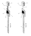
- FIGS. 2A-B are perspective views of electrical connections that can be formed with contact pads of a thermocouple device.
- FIG. 3 is a schematic showing an example of a plurality of thermocouple junctions that can be suitably configured to create multiple thermocouple junctions at different locations on a medical device.
- FIG. 5 is a schematic of the control elements that allow a thermocouple device to act as a radio-frequency coil.
- the control elements include a thermocouple reader which could be used to provide a read out of the temperature detected by the thermocouple.
- Another control element which may be coupled to the thermocouple device is shown as RF power supply. This power supply could be used, for example, to generate RF in the thermocouple. The RF power supply could be readily replaced with a RF detector to monitor or detect RF.
- An optional control element is shown as the switching circuit. This switching circuit could be functionally coupled to a timing circuit that allows for suitably timing the switching circuit. The switching circuit allows for switching the coupling of the thermocouple reader and the RF power supply to the thermocouple element.
- FIG. 6 is a schematic view showing an example of a thermocouple device that functions simultaneously and continuously as a thermocouple and a radio-frequency coil.
- the circuits connected to the device can be configured such that both the radio-frequency coils and the thermocouple reader are continuously functioning to read the temperature and generate radio-frequency.
- the RF power supply can also be replaced with a RF detector to continuously monitor and detect RF.
- FIGS. 8A-C show perspective views of various embodiments of a thermocouple device that may also be used as a heater.
- the dimensions of the heater element can be easily configured according to the heating requirements and the use of the heating element.
- FIGS. 9A-B show yet another embodiment of a thermocouple device of the present invention that may be used as a heater.
- FIG. 9A shows a top view of the thermocouple device where the heater element is configured, for example, in a coil.
- FIG. 9B shows a side cross-sectional view of the thermocouple device.
- FIG. 10 shows a schematic diagram of the control elements couple to a heater thermocouple device that allows the device to act as a heater and as a thermocouple.
- the control elements include a thermocouple reader which could be used to provide a read out of the temperature detected by the thermocouple.
- Another control element which may be coupled to the heater thermocouple device is shown as the heater power supply. This heater power supply could be used, for example, to generate heat in the heater element of the thermocouple.
- An optional control element is shown as the switching circuit. This switching circuit could be functionally coupled to a timing circuit to permit suitably timed coupling of the thermocouple reader and the heater power supply to the heater thermocouple element.
- FIGS. 12A-E show cross-sectional views of the sequential fabrication steps that may be used in constructing a thermocouple device of the present invention.
- the steps shown on the left are cross sections along section AA in FIG. 1 and the steps shown on the right are cross sections along section AA in FIG. 2A .
- FIG. 13 is a graph showing experimental temperature readings from a thermocouple device of the present invention as a function of time where the ambient temperature is programmed to fluctuate.
- the present invention relates to a thermocouple device comprising a flexible non-planar substrate, a first printed thermocouple element comprising a first metal containing ink composition applied to the flexible non-planar substrate, and a second printed thermocouple element in electrical contact with the first printed thermocouple element making a thermocouple junction.
- the second printed thermocouple element comprises a second metal containing ink composition with a Seebeck coefficient sufficiently different from the first metal containing ink composition for the first and second printed thermocouple elements to together produce a thermocouple effect.
- thermocouple devices of the present invention can be used as temperature sensors and comprise a thermocouple having elongated ends joined together at their distal ends to form the thermocouple and their proximal ends connected to a connector mounted in the catheter.
- External equipment may be connected to the connector of the catheter to receive the temperature signals of the thermocouple for signal processing to determine the temperature sensed.
- the thermocouple is typically disposed at the distal end of the catheter.
- the present invention provides a temperature measurement device printed directly to a three dimensional surface, for example a medical device, without the disadvantages noted supra.
- the thermocouple device 10 includes a first printed thermocouple element 12 connected to a first contact pad 14 using a first metal-containing ink composition.
- a second printed thermocouple element 16 connected to a second contact pad 18 are formed using a second metal-containing ink composition such that the thermocouple elements 12 and 16 contact each other and form a thermocouple junction 20 .
- the first and second metal-containing ink compositions are chosen such that the thermoelectric EMF formed at thermocouple junction 20 due to the Seebeck effect is of a useful magnitude.
- the thermocouple device 10 is disposed on substrate 100 .
- the substrate 100 includes any non-planar or “three dimensional” medical device which could be, for example, a medical device.
- the non-planar substrate could be, for example, a cylindrical object, a spherical object, a wire, a catheter, a fabric, a multi-branching substantially tubular device, or a flexible non-planar substrate which may distort upon application of force.
- the substrate 100 could be polymeric, ceramic, metallic, or a combination thereof.
- the substrate 100 could have elastic properties ranging from highly flexible to extremely rigid. Many of the aspects of the present invention are particularly well suited for the formation of thermocouple devices on flexible, polymeric medical devices. However, the present invention is not intended to be limited by either the materials of construction or the elastic properties of the substrate 100 .
- thermocouple device of the present invention further comprises electrical connectors electrically coupled to the first and the second printed thermocouple elements.
- these electrical connectors could also be connected to multiple printed elements at multiple locations using the techniques described in the present invention.
- a person of skill in the art can readily configure the electrical connectors to be suitably connected for different configurations of the thermocouple device.
- thermocouple device of the present invention can comprise a voltage reader operably coupled to the electrical connectors to measure the voltage between the first and second printed thermocouple elements.
- the voltage is generated due to the temperature differential between the first and the second printed thermocouple elements.
- This voltage can be calibrated to temperature to provide a direct readout of the temperature.
- standardized data sets could be provided to convert the voltage reading to temperature (see for example, FIG. 13 ).
- the electrical connectors could also be coupled to a voltage source which can be used to apply current to the first and the second printed thermocouple elements, thereby providing heating or cooling to the thermocouple junction.
- thermocouple device of the present invention comprises an overcoat layer covering the first and second printed thermocouple elements.
- the surface or substrate materials used to print the thermocouples may be non-conducting or coated with a non-conducting layer(s).
- thermocouple device of the present invention comprises an intermediate layer positioned between the flexible non-planar substrate and the first and second printed thermocouple elements.
- the intermediate layer could function in many ways, such as a sealing layer, insulating layer, adhesive layer, structural support layer, or a combination thereof.
- Non-limiting examples of polymeric materials that may be used to manufacture these aspects of the present invention include epoxy, polyacrylate, silicone or natural rubber, polyester, polyethylene napthalate, polypropylene, polycarbonate, polystyrene, polyvinyl fluoride ethyl-vinyl acetate, ethylene acrylic acid, acetyl polymer, poly(vinyl chloride), silicone, polyurethane, polyisoprene, styrene-butadiene, acrylonitrile-butadiene-styrene, polyethylene, polyamide, polyether-amide, polyimide, polyetherimide, polyetheretherketone, polyvinylidene chloride, polyvinylidene fluoride, polycarbonate, polysulfone, polytetrafluoroethylene, polyethylene terephthalate, polyhydroxyalkanoate, poly(p-xyly
- the first and the second metal containing ink compositions of the present invention independently comprise a metal powder selected from the group consisting of copper, palladium, chromel, alumel, rhenium, nickel-chromium-silicon, constantan, cadmium, aluminum, platinum, rhodium, iridium, molybdenum, tantalum, beryllium, zinc, tin, chromium, nickel, nickel-chromium, nickel-aluminum, nickel-silicon, iron, tungsten, lead, silver, gold, magnesium, silicon or alloys thereof.
- a metal powder selected from the group consisting of copper, palladium, chromel, alumel, rhenium, nickel-chromium-silicon, constantan, cadmium, aluminum, platinum, rhodium, iridium, molybdenum, tantalum, beryllium, zinc, tin, chromium, nickel, nickel-chromium, nickel-aluminum, nickel-silicon,
- thermocouple junction and leads may be formed from any two metals exhibiting sufficiently different Seebeck coefficients.
- the Seebeck coefficient typically varies with temperature, so selection of metal pairs should also minimize any nonlinearities in the difference over the temperature range of interest. Range and accuracy of measurement may be affected by choice of materials, and many standard metal pairs have been identified and are commonly used as thermocouples.
- a copper-constantan junction defines a T-type thermocouple; while a combination of platinum and a platinum-rhodium alloy yields a Type R or Type S thermocouple, depending on the rhodium content in the alloy.
- thermocouple metal pairs include chromel-constantan (Type E); iron-constantan (Type J); chromel-alumel (Type K); and nicrosil-nisil (Type N).
- Many non-standard thermocouples can also be envisioned, such as silver-nickel, copper-nickel, tungsten-nickel, gold-palladium, etc.
- Semiconductor materials also make excellent thermocouples; however it is difficult to obtain connection wires made of such materials so they are normally only useful for solid-state applications where interconnects are not required. With respect to ready availability of ink materials and a clearly detectable reproducible temperature signal, silver-nickel or tungsten-nickel are most preferred.
- Additives and fillers are often present in the polymer matrices of the present invention in order to improve mechanical properties, enable processing, and add radiopacity to the devices.
- the surface of the polymer may be further modified to enhance biocompatibility or to alter frictional or adhesive properties through application of: additional polymeric, oligomeric, or surfactant coating layers; mechanical or chemical etching; or plasma, corona, or flame treatment.
- the first, second or other metal containing ink compositions independently comprise a binder selected from the group consisting of poly(vinyl chloride), silicone, polyurethane, polyisoprene, styrene-butadiene, acrylonitrile-butadiene-styrene, polyethylene, polyamide, polyether-amide, polyimide, polyetherimide, polyetheretherketone, polyvinylidene chloride, polyvinylidene fluoride, polycarbonate, polysulfone, polyethylene, polytetrafluoroethylene, polyethylene terephthalate, polyhydroxyalkanoate, poly(p-xylylene), liquid crystal polymer, polymethylmethacrylate, polyhydroxyethylmethacrylate, polylactide, polyglycolide, polyisoprene, polycaprolactone, cyanoacrylates, polyvinyl butyral, polyvinyl formal, polyethylene oxide, polyvinyl butyral, polyvinyl formal, poly
- the ink or paste should comprise a polymeric binder combined with a sufficient level of metallic particles to afford contiguous contact of the particles in the dry form.
- the polymeric binder may be selected from any of the commonly available thermoplastic or thermoset polymers, or combinations thereof, in order to yield the most optimal properties.
- the polymer may be dissolved or dispersed in an organic solvent which also may play a role in enhancing adhesion to the substrate device.
- Additives may be present in the ink or paste, including but not limited to crosslinkers, catalysts, inhibitors, dispersants, surfactants, thickeners, matting agents, and the like as required to optimize both the manufacturing process and the properties of the final product.
- the optimal binder polymer may comprise polydimethylsiloxane, along with appropriate crosslinking chemistry to yield a sufficiently robust matrix for the metal particles.
- an optimal binder polymer for the printing ink may be poly(vinyl chloride) dissolved in a solvent which slightly swells the substrate to allow entanglement of the ink polymer and the substrate polymer, leading to optimal adhesion.
- Solvents which may be used in the present invention include, without limitation: any liquid capable of dissolving or dispersing the ink binder polymer, such as paraffinic hydrocarbons such as cyclohexane; aromatic hydrocarbons such as toluene or xylene; halohydrocarbons such as methylene dichloride; ethers such as anisole or tetrahydrofuran; ketones such as acetone, methyl ethyl ketone or methyl isobutyl ketone; aldehydes; esters such as ethyl carbonate, 4-butyrolactone, 2-ethoxyethy acetate or ethyl cinnamate; nitrogen-containing compounds such as n-methyl-2-pyrrolidone or dimethylformamide; sulfur-containing compounds such as dimethyl sulfoxide; acid halides and anhydrides; alcohols such as ethylene glycol monobutyl ether, a-terpineol, ethanol, or
- Preferred solvents are those which have the lowest toxic potential when left behind in residual quantities, such as acetone, 1-butanol, ethanol, 1-propanol, methyl acetate, anisole, methyl acetate, methyl ethyl ketone, and the like. Combinations of solvents sometimes prove especially useful in obtaining good solubility with minimal risk of toxicity. It is preferable to choose solvents which evaporate at a rate such that the temperature of the polymeric substrate can be maintained below its softening point, so that the device is not damaged as the solvent is driven off.
- thermocouple device 10 electrical connection of thermocouple device 10 to other modules used, for example, to detect or supply power can be accomplished in many ways.
- a first interconnection assembly 30 consisting of a first conductor 31 surrounded by a first insulator 32 , communicates electrically with the first contact pad 14 through a first bonding material 40 .
- a second interconnection assembly 34 consisting of a second conductor 35 surrounded by a second insulator 36 , communicates electrically with the second contact pad 18 through a second bonding material 42 .
- first contact pad 14 , first conductor 31 , and first bonding material 40 must be constructed of the same metal or metal alloy.
- second contact pad 18 , second conductor 35 , and second bonding material 42 must also be constructed of the same metal or metal alloy.
- the bonding materials 40 and 42 are epoxy adhesives filled with the appropriate metal or metal alloy flakes or powders.
- An example of a preferred silver-containing epoxy is Epo-Tek® H20E sold by Epoxy Technology, Inc® (Billerica, Mass.).
- the bonding materials 40 and 42 are the printed thermocouple element inks themselves.
- An example of a preferred nickel-containing ink is 116-25 sold by Creative Materials, Inc. (Tyngsboro, Mass.).
- Alternative methods of creating connections to thermocouple device 10 include ultrasonic bonding, swaging, screw terminals, pressure contacts, soldering, and brazing.
- thermocouple device of the present invention may comprise first and second printed thermocouple elements which collectively have a thickness of 0.1 to 500 microns.
- thermocouple device could be such that the first and second printed thermocouple elements collectively have a thickness of 12 to 80 microns
- thermocouple device of the present invention can comprise a plurality of thermocouple junctions formed by a combination of a plurality of printed thermocouple elements.
- a plurality of thermocouple junctions may be used to increase the area over which temperature measurements are taken.
- the multiple printed thermocouple elements can be utilized to create multiple thermocouple junctions disposed at specific locations on a medical device. This allows the gathering of temperature information over a region of the medical device rather than at a single point.
- thermocouple junction 22 can be produced by providing a third contact pad 82 connected to a third printed thermocouple element 80 which in turn comes in contact with the first printed thermocouple element 12 .
- a fourth printed thermocouple element 84 connected to a fourth contact pad 86 can be utilized to create a third thermocouple junction 24 .
- the multiple thermocouple junctions can be precisely located across the medical device substrate to provide temperature measurements over an area rather than at a single point.
- the positions of the thermocouple junctions, the materials used to form the printed thermocouple elements, and the electrical topology of the junctions can all be varied for the needs of a particular application. All combinations thereof are within the scope of the present invention.
- thermocouple device of the present invention can be disposed on, for example, a substantially cylindrical medical device substrate such that a significant portion of the thermocouple device forms a solenoidal electrical coil that can be used to deliver or sense electromagnetic fields and energy.
- the thermocouple device can alternatively be read as a temperature sensor and energized to provide localized radio-frequency heating.
- thermocouple device of the present invention can further comprise a voltage reader operably coupled to the electrical connectors to measure the voltage between the first and/or second printed thermocouple elements and a radio frequency module operably coupled to the electrical connectors of the first and/or second printed thermocouple elements to generate radio frequency waves or to detect radio frequency waves.
- a substantially cylindrical thermocouple device 11 can be formed on a substantially cylindrical medical device substrate 102 . “Substantially cylindrical” means that at least a portion of the medical device substrate is closed and sufficiently well-behaved to permit the printing of one or more coils or loops.
- the actual cross-section of the medical device substrate is ideally circular, but may also be elliptical, polygonal, or an arbitrary shape.
- the cross-section may also vary with axial position.
- the substantially cylindrical thermocouple device 11 is disposed such that it forms in part a multi-loop solenoid coil which can sense or transmit electromagnetic fields and energy.
- thermocouple device of the present invention comprises the radio-frequency module which can be, for example, a radio frequency generator, radio frequency detector, or a combination thereof.
- thermocouple device of the present invention further comprises a switching module which selectively couples the electrical connectors of the first and/or second printed thermocouple elements to the voltage reader or the radio frequency module.
- the substantially cylindrical thermocouple device 11 can be made to function as both a temperature sensor and either a sensor or transmitter of electromagnetic fields and energy by connecting the first and second interconnection assemblies 30 and 34 to a switching circuit 70 which alternately connects the device to a thermocouple reader 74 to take temperature measurements or to, in one preferred embodiment, a RF power supply 78 to excite the solenoid coil in the substantially cylindrical thermocouple device 11 in order to couple electromagnetic fields and/or energy into body tissue.
- a timing circuit 72 is utilized to control the switching circuit 70 .
- the scheme of FIG. 5 would be used to ablate tissue and monitor the local temperature in order to control the procedure. It should be noted that the flat coil and the solenoid coil differ primarily in geometry and are equally able to be employed and controlled by the scheme of FIG. 5 .
- thermocouple device of the present invention can have the electrical connectors of the first and/or second printed thermocouple elements permanently connected to the voltage reader and the radio frequency module.
- FIG. 6 an alternative preferred embodiment of the substantially cylindrical thermocouple device 11 of FIG. 4 is depicted.
- a three-terminal thermocouple device 200 is constructed by forming the second printed thermocouple element 16 into a multi-turn solenoid coil and terminating it at a common lead contact pad 90 .
- the thermocouple junction 20 is formed by contacting the first printed thermocouple element 14 to one of the coils.
- a third interconnection assembly 38 communicates electrically with the common lead contact pad 90 .
- the thermocouple reader 74 is used to produce temperature measurements.
- thermocouple reader is connected between the first and third interconnection assemblies 30 and 38 .
- the RF power supply 78 is used to provide RF energy.
- the RF power supply is connected between the second and third interconnection assemblies 34 and 38 .
- thermocouple device permits simultaneous and continuous temperature measurements while a specific section of the thermocouple device is utilized as, for example, a heater, a RF heater, or an electromagnetic field sensor. This arrangement reduces terminal count and reduces the complexity of interconnection.
- the present invention relates to a heated thermocouple device comprising a flexible non-planar substrate, a first printed thermocouple element comprising a first metal containing ink composition applied to the flexible non-planar substrate and a second printed thermocouple element applied to the flexible non-planar substrate.
- the second printed thermocouple element comprises a second metal containing ink composition with a Seebeck coefficient sufficiently different from the first metal containing ink composition for the first and second printed thermocouple elements to together produce a thermocouple effect.
- the heated thermocouple device further comprises a heater element applied to the flexible non-planar substrate.
- the heater element comprises a third metal containing ink composition and is electrically connected to the first and second printed thermocouple elements.
- thermocouple device the geometry and electrical properties of the metallic elements that make up the thermocouple device can be adjusted to create a section of the device that possesses a large portion of the overall series resistance of the device. This section then acts as a heater element that delivers localized energy when the thermocouple device is actively driven with a power supply.
- the heated thermocouple device of the present invention further comprises electrical connectors electrically coupled to the first and the second printed thermocouple elements.
- electrical connectors electrically coupled to the first and the second printed thermocouple elements.
- a person of skill in the art can readily configure the electrical connectors to be suitable for different configurations of the heated thermocouple device. Depending on the design of the thermocouple device, these electrical connectors could be connected to multiple printed elements at multiple locations using the techniques described in the present invention. Depending upon the design of the device, the electrical connectors can also be independently attached to the heater element of the heated thermocouple element.
- thermocouple device can alternatively be viewed as a three-section device where a heater element 60 is specifically identified and communicates electrically with the second printed thermocouple element 16 through a heater element connection 21 .
- Heater element 60 is constructed of the same metal or metal alloy as the second printed thermocouple element 16 and, consequently, the thermocouple junction 20 is formed at the interface between heater element 60 and the first printed thermocouple element 12 .
- heater element 60 can be specifically designed to be highly resistive relative to the first and second printed thermocouple elements 12 and 16 so that when the thermocouple device 10 is electrically excited most of the Joule heating in the device is confined to heater element 60 .
- a heater element based on trace thickness 62 can be formed by reducing the thickness of the printed trace.
- a heater element based on trace width 64 can be formed by reducing the width of the printed trace.
- a heater element based on material formulation 66 can be formed by increasing the bulk resistivity of the trace by, for example, reducing the concentration of the metal or metal alloy filler in the ink. It should be noted that, depending on the printing methodology employed, the fabrication of the heater element may require a printing step separate from that employed to produce the second printed thermocouple element 16 .
- a fourth approach according to the present invention is to create a heater element based on trace length 68 .
- the heater element could be disposed as a single line, a serpentine, an irregular polygon, or some other shape.
- the coil is shown explicitly in FIG. 9A and is especially preferred for two reasons.
- the coil geometry allows the heater element to be designed for precise delivery of heat over a large area.
- the coil structure provides the thermocouple device with an electrical inductor which may be used to either sense or transmit electromagnetic fields and energy.
- the coil geometry does involve at least one added fabrication step.
- an interlayer dielectric 69 is used to electrically isolate the coil from the first printed thermocouple element 12 .
- the resistance of the heater element can be varied through trace thickness, width, bulk resistivity, or length as well as any combination thereof.
- the heated thermocouple device of the present invention can further comprise a voltage reader operably coupled to the electrical connectors to measure the voltage between the first and second printed thermocouple elements and to a voltage source operably coupled to the electrical connectors to apply current to the first and second printed thermocouple elements. Also, by providing switching and timing circuitry, the thermocouple device can alternatively be read as a temperature sensor and energized to provide localized heating.
- the heated thermocouple device of the present invention can comprise a switching module which selectively couples the electrical connectors of the first and second printed thermocouple elements to the voltage reader or the voltage source.
- the thermocouple device 10 can be made to function as both a heater and a temperature sensor by connecting the first and second interconnection assemblies 30 and 34 to a switching circuit 70 which alternately connects the device to a thermocouple reader 74 to take temperature measurements or to a heater power supply 76 to excite the thermocouple device 10 to produce heat.
- a timing circuit 72 is utilized to control the switching circuit 70 .
- the present invention is related to a medical device comprising the thermocouple device of the present invention.
- the medical device could be a three-dimensional polymeric medical device having a functional thermocouple applied directly and permanently on its surface by an industrial printing or direct-writing technique.
- Medical devices are generally defined by the United States Food and Drug Administration as “an instrument, apparatus, implement, machine, contrivance, implant, in vitro reagent, or other similar or related article, including a component part, or accessory which is: 1) recognized in the official National Formulary, or the United States Pharmacopoeia, or any supplement to them; 2) intended for use in the diagnosis of disease or other conditions, or in the cure, mitigation, treatment, or prevention of disease, in man or other animals; or 3) intended to affect the structure or any function of the body of man or other animals, and which does not achieve any of it's primary intended purposes through chemical action within or on the body of man or other animals and which is not dependent upon being metabolized for the achievement of any of its primary intended purposes.”
- the medical device of the present invention comprises a plurality of thermocouple junctions formed by a combination of a plurality of the printed thermocouple elements.
- the medical device of the present invention can be operably connected to another device to control or monitor the other device's function.
- a secondary functional device 50 may also be present simultaneously with thermocouple device 10 .
- Secondary functional device 50 may include active element 52 and accompanying electrical leads 54 .
- Some examples of secondary functional device 50 include: transducers to transmit electromagnetic fields, electromagnetic energy, heat, light, force, pressure, or medicaments to body tissues; sensors to detect electromagnetic fields, electromagnetic energy, light, force, pressure, pathogens, chemical species, or biological entities.
- Secondary functional device 50 and thermocouple device 10 may be in close proximity and may communicate thermally. Thermocouple device 10 may be used to monitor, control, or guide the use of secondary functional device 50 .
- thermocouple device 10 could be connected to a control system where a temperature set point acts as a trigger to turn secondary functional device 50 on or off.
- a temperature set point acts as a trigger to turn secondary functional device 50 on or off.
- the presence or absence of any secondary devices, coatings, or other functional elements on the medical device is coincidental to the present invention.
- the medical devices of the present invention include, but are not limited to, endotracheal tubes, endobronchial tubes, cannulae, catheters, balloons, stents, airways, sensors, stimulators, implants, intraocular or contact lenses, cochlear implants, and orthopedic implants or prostheses and the like.
- Sensors can include sensing capsules, stimulators, and the like. While drug-eluting stents or other drug-eluting devices do not strictly conform to the definition above, they are considered primarily as medical devices and therefore are encompassed by the present invention.
- thermocouples printed directly on medical devices is extremely useful in a variety of situations. For example, core body temperature may be measured directly during a procedure without introducing an additional device. During radio frequency ablation procedures, the temperatures of the probe and surrounding tissue must be controlled so that unintended damage does not occur, and a thermocouple printed directly on an ablation device is useful in providing a feedback information for the cooling mechanism. Another useful application for thermocouples printed directly on medical devices is to provide a means of precisely detecting the location of cancerous lesions or areas of inflammation, since they exhibit higher temperatures than surrounding tissue.
- Radiopaque traces may also be printed directly on the medical device of interest in order to accurately visualize its position during a procedure.
- the thermocouple could be used to work as a heat source which controls the temperature requirements for functioning of a medical device or drug delivery agent.
- a further aspect of the present invention relates to a method of forming a thermocouple device.
- the method comprises applying a first metal containing ink composition to a flexible non-planar substrate, where the first metal containing ink composition forms a first printed thermocouple element and applying a second metal containing ink composition to the first metal containing ink composition applied to the flexible non-planar substrate where the second metal containing ink composition forms a second printed thermocouple element.
- the first and second metal containing ink compositions have a Seebeck coefficient sufficiently different from one another so that the first and second printed thermocouple elements together produce a thermocouple effect.
- FIGS. 12A-E illustrate the fabrication sequence of thermocouple device 10 .
- the cross sections shown correspond to Section AA of FIG. 1 (see left side of FIG. 12 ) and Section AA of FIG. 2A (see right side of FIG. 12 ).
- FIG. 12A depicts the application of intermediate layer 110 , which has been omitted in FIGS. 1 and 2 .
- Intermediate layer 110 is an optional layer which may be used, for example, to: improve adhesion between medical device substrate 100 and the thermocouple materials; provide additional stiffening if medical device substrate 100 proves too flexible to adequately support the thermocouple traces; or provide electrical isolation if medical device substrate 100 possesses electronic or ionic conductivity such that it interferes with the proper functioning of thermocouple device 10 .
- Note that for simplicity of presentation the presence of intermediate layer 110 is omitted in FIGS. 12B-E and all subsequent figures.
- first printed thermocouple element 12 and first contact pad 14 are disposed on medical device substrate 100 .
- thermocouple element 16 and first contact pad 18 are disposed on medical device substrate 100 .
- the contact interface between the first and second thermocouple elements 12 and 16 forms the thermocouple junction 20 .
- printed trace overcoat 44 is a dielectric layer disposed over the first and second thermocouple elements 12 and 16 but not the first and second contact pads 14 and 18 .
- Printed trace overcoat 44 protects the printed elements from ions, moisture and friction and provides support against stress.
- Printed trace overcoat 44 can also provide a means for conduction of heat from the external medium to the thermocouple or be used as a means of enhancing flexibility and providing support to the device.
- Printed trace overcoat 44 may be laced with materials that impart desirable properties such as radio opacity, enhanced thermal conductivity, temperature controlled chemical release of medicaments, or the ability to carry other medical devices (e.g., a glucose meter).
- printed trace overcoat 44 ensures that any irritation or toxicity inherent to the metal or its binder is isolated from the body tissues.
- Any biocompatible, non-conductive, impermeable polymer which is easily applied may be used. Medical grade silicones, such as those provided by NuSil® (Bakersfield, Calif.), or medical grade acrylate adhesives, such as those provided by Dymax® (Torrington, Conn.), are particularly preferred.
- Dymax® Torrington, Conn.
- thermocouple device 10 the formation of interconnections to thermocouple device 10 is accomplished by bringing first contact pad 14 into electrical communication with first conductor 31 through the use of first bonding material 40 which is subsequently cured in an appropriate fashion. Following the cure, interconnection overcoat 46 is applied to electrically isolate and hermetically seal the interconnection junction. Not shown in FIG. 12E is the subsequent and final step of connecting second contact pad 18 and providing an interconnection overcoat.
- the applying steps in forming the thermocouple device are carried out by direct writing.
- the applying steps may be independently carried out by screen printing, jetting, laser ablation, direct writing, or pressure driven syringe delivery.
- Microdispensing techniques such as Micropen® direct writing are particularly preferred for marking of medical devices, due to their ability to accommodate inks having an extremely wide range of rheological properties and very high solids levels, as well as excellent three dimensional substrate manipulation capabilities.
- a Micropen® can be used to apply the lines of the two or more selected thermo-element inks or paints such that they overlap at the location where the temperature is to be measured. These lines can then be extended to a convenient area where the thermocouple extension conductors can be attached to connect the cold junctions and instrumentation.
- thermocouple elements This technique is especially suited for flexible objects, as the writing force is continuously adjusted to compensate for substrate morphology, so that permanent deformation of the surface is not a concern.
- a major advantage of using a microdispensing technique to write the thermocouple elements is that the tip of the pen does not come in direct contact with the substrate during the writing process. This makes it a preferable method for writing thermocouple elements, because no distortion of the substrate is expected during the writing process.
- a liquid or paste ink is generally used.
- metals, to be included in the ink are selected from those already available in printable ink form or those that are available in a particulate form that can easily be dispersed into a printable ink or paste.
- wires comprised of the metals should also be readily formed or commercially available in order to form the leads to the measurement device and avoid the presence of a secondary junction.
- nickel particles and inks are common and relatively inexpensive.
- Copper or tungsten inks and particles are also commonly available, as are noble metals such as silver, platinum, and palladium.
- Metallic alloys also may be produced in powder or flake form via atomization or attrition and then formulated into printable inks. For example, constantan, chromel, or alumel can be formed by spray atomization and then made into an ink intended to be used in a thermocouple.
- Silver ink was prepared by dissolving poly(vinyl chloride) (high molecular weight, Sigma ALDRICH® at a level of 13% by weight in a mixture of tetrahydrofuran, n-methyl pyrrolidone and ⁇ -terpineol in a ratio of 55:36:9 by weight.
- Silver flake (10 ⁇ m, >99.9%, SIGMA-ALDRICH® was added to yield a ratio of silver:poly(vinyl chloride) of 85:15.
- the total solids were 50% by weight.
- the materials were combined using a planetary high shear mixer (KURABO MAZERUSTAR KK-50S)
- Nickel ink was prepared by dissolving poly(vinyl chloride) (high molecular weight, Sigma-ALDRICH® at a level of 13% by weight in a mixture of tetrahydrofuran, n-methyl pyrrolidone and ⁇ -terpineol in a ratio of 67.5:26:6.5 by weight.
- Nickel powder (3 ⁇ m, 99.7%, SIGMA-ALDRICH® was added to yield a ratio of nickel:poly(vinyl chloride) of 85:15. The total solids were 44% by weight.
- the inks were loaded into syringes and extruded through a MicroPen® direct writing device onto the surface of a commercially available standard endotracheal tube (UNOMEDICAL® AIR MANAGEMENT, Magill, HVLP cuff) to yield two thermocouple junctions; one printed on the inflated cuff of the endotracheal tube and the other printed on the side of the tube itself just below the cuff ( FIG. 1 ). The junctions were extended to allow for subsequent interconnection. The inks were then written and cured (forced air, 130° C., 1 hour) with silver followed by nickel.
- nickel wire SCIENTIFIC INSTRUMENT Services®, 0.5 mm diameter
- silver wire Alfa Aesar, 0.5 mm diameter, 99.9%
- thermocouple reader Acromag® Model 965EN-4006
- endotracheal tube placed in a programmable oven.
- the temperature was cycled from ambient 25° C. to 120° C. in 2 hours, then ramped back to room temperature at the same rate.
- Voltage data was collected using the LABVIEW® software program from 30° C. to 120° C. and back to 30° C. The heating and cooling rates were identical at 45° C./hour. Six data point was collected each minute of testing. For comparison, data was simultaneously collected for a commercially available Type K thermocouple (OMEGA ENGINEERING, Inc.®) placed in the oven near the tube.
- OEGA ENGINEERING, Inc.® Type K thermocouple
- thermocouple junction on the tube was tested and a linear response was obtained for voltage vs temperature, yielding a slope of 20 ⁇ V/C.
- the data nearly precisely overlaid for both heating and cooling cycles. The temperature ramps were repeated and the data was duplicated.
- Thermocouples were prepared in a manner identical to that described in Example 1, except the solvent used for the inks was cyclohexanone. Also, nickel flake ( ⁇ 325 mesh, 0.37 microns thick, 99.8%, Alfa Aesar®) was used instead of nickel powder, and the final percentage of solids of the nickel inks was adjusted to 46% by weight.
- junctions and traces were printed onto the surface of an endotracheal tube using Micropen® direct writing device as described in Example 1—i.e. cured, covered with a polymeric encapsulant, and leads attached as described previously.
- thermocouple junction on the tube was tested as described in Example 1, except in this case the maximum temperature was raised to 130° C., yielding a response of 20 ⁇ V/C for heating and cooling.
- thermocouple junction on the cuff was evaluated similarly, except the maximum temperature reached was 140° C. Also, after the heating cycle was completed, a cooling cycle was carried out in an environmental test chamber (Model BTRC, Tenney® Environmental) down to ⁇ 40° C. Then, the temperature was raised back to room temperature. The data collected was linear, repeatable, and indicated a sensitivity of 18 ⁇ V/° C.
- Thermocouples were prepared identically to Example 1, except commercially available metallic inks were use.
- the silver ink used was 101-59 (Creative Materials, Inc. (Tyngsboro, Mass.)) and the nickel inks used was 116-25 (Creative Materials, Inc. (Tyngsboro, Mass.)).
- the nickel ink was bonded to the nickel wire using the nickel ink as an adhesive; and the silver wire was bonded using a silver epoxy (Epo-Tek® H20E; Epoxy Technology, Inc (Billerica, Mass.)).
- thermocouple junction positioned on the cuff was evaluated on heating and cooling from 25° C. to 145° C. and back, and had a sensitivity of 20 ⁇ V/° C.
Abstract
In one aspect, the present invention relates to a thermocouple device comprising a flexible non-planar substrate, a first printed thermocouple element comprising a first metal containing ink composition applied to the flexible non-planar substrate, and a second printed thermocouple element in electrical contact with the first printed thermocouple element making a thermocouple junction. The second printed thermocouple element comprises a second metal containing ink composition with a Seebeck coefficient sufficiently different from the first metal containing ink composition for the first and second printed thermocouple elements to together produce a thermocouple effect. The present application further relates to medical devices comprising the thermocouple and methods of making such devices.
Description
This application claims the benefit of U.S. Provisional Patent Application Ser. No. 61/315,534, filed Mar. 19, 2010, which is hereby incorporated by reference in its entirety.
The present invention is related to a printed thermocouple device and its uses.
Common options for measuring temperature include the Resistance Temperature Detector (RTD), which has a metallic element possessing a positive temperature coefficient of resistance (decreasing resistance with increasing temperature), or a thermistor, which has a metal oxide element exhibiting a negative temperature coefficient (increasing resistance with increasing temperature). Unlike an RTD, thermocouples can achieve high accuracy without any restrictions on target immersion depth relative to the sensor diameter or length. Unlike a thermistor, thermocouples produce signals without any pronounced nonlinearity with temperature, thus allowing use over a greater temperature range. Finally, unlike a thermal colorimetric material, additional internal sensors are not necessary in order to obtain the signal. These factors make thermocouples particularly useful when used on medical devices, because they have superior capability for measuring temperature in a small or confined area. Accurate measurements of tissue or body fluids temperature are critically important during many medical procedures, but introduction of temperature measurement capability at a specific, controllable location during the procedure is often difficult and sometimes impossible. Application of a thermocouple device directly on a medical device solves this problem, removes uncertainty, during the procedure, about the exact location of the probe, and reduces the number of instruments that must be introduced or used during the medical procedure.
Thermocouples use two leads formed of dissimilar materials, for example one lead formed of constantan and the other formed of copper, that are joined at one end to form a thermocouple junction. The thermocouple junction produces a voltage, representative of the temperature, and that voltage varies as the thermocouple is exposed to various temperatures. Conventional thermocouples are often formed by joining together a pair of dissimilar metal wires, the metals having been chosen so that a voltage is observed depending on the size of the temperature difference between the joined and free ends of the pair.
Thermocouples can be used for both temperature measurement and temperature control by heating the thermocouple junction. The thermocouple effect is where a temperature differential can be converted directly into electrical energy, with the amount of electrical energy so generated providing a measurement of the temperature. The observed voltage then provides an estimate of the temperature differential along the length of the pair of wires according to standard equations well known to those of ordinary skill in the art.
Conversely, if a voltage is applied to a thermocouple, a temperature differential is created between the junction and the free ends of the two elements that comprise the thermocouple, with the junction being either cooled or heated depending on the direction of the applied DC current. If a number of such thermocouples are interconnected, a heating and cooling module (e.g., a Peltier module) may be constructed according to methods well known in the art. Several thermocouples that have been interconnected in series are often also commonly referred to as a thermopile.
As useful and versatile as modern thermocouples might be, they suffer from certain disadvantages, among which are that they are generally not suitable for use on flexible/irregular surfaces. Thermocouples are often made of thin wire pairs so that the device responds more quickly to temperature changes, but such a construction can make the thermocouple somewhat fragile. Several inventions have been aimed at demonstrating and solving the problems inherent in placing a temperature-measuring device directly on or in a medical device, but they have drawbacks and technical limitations.
For example, U.S. Patent Publication No. 2005/0257822 to Smith et al., describes printing finely powdered metals onto bedsheets and the like for use in medical scenarios. The metals are formulated into inks and deposited via silk screening. Silk screening is a popular printing method for applying lines to flexible objects. However, the objects must be held against a noncompliant backing during printing, such that silk screening is limited to two-dimensional or planar surfaces. Most medical devices of interest are polymeric, flexible, and three dimensional, rendering the silk screening approach problematic and often unusable. The silk screening method applies pressure to the substrate during the writing process.
U.S. Pat. No. 4,263,921 to Trugillo et al., describes a temperature sensitive endotracheal tube in which a thermistor is mounted to the tube. Mounting the thermistor rather than writing it directly on the tube surface leads to unwanted protrusion on the surface of the device which may prove damaging or uncomfortable upon introduction of the device to measure temperature during medical procedures. Further, there is an increased risk of the temperature sensor becoming loose and getting displaced during the procedure, leading to uncertainty in probe localization and subsequently in temperature monitoring. Another issue with the design is that thermistors, which rely on changes in resistance vs. temperature for a single metal, exhibit more non-linearity with temperature than do thermocouples, leading to measurement errors or the need for complicated correction algorithms during signal processing.
U.S. Pat. No. 4,046,139 to Horn describes a temperature sensor mounted on the cuff of an endotracheal tube, which could be a thermocouple, thermistor or color-sensitive material. A mounted thermocouple or thermistor would have the same drawbacks discussed above. Furthermore, a temperature sensor reliant on color change would be of limited usefulness when embedded in the body, because a method of sensing and transmitting the color, such as a camera or CCD, would also need to be introduced in able to detect real-time temperature changes.
U.S. Pat. No. 5,596,995 to Sherman et al., describes a thermocouple affixed to an end of a catheter. However, another thermocouple junction is formed where the leads are connected to dissimilar metals. Sherman describes a method for compensating for the unintentional second thermocouple formed at this connection. The electronics are formed separately from the device and then mounted to the device, leading to manufacturing challenges particularly if the catheter is very small in diameter; and also leading to the possibilities outlined above that the thermocouple junctions may be inadvertently displaced during the procedure. Like the other cases, a method is not provided that elegantly affixes the metals to the medical device.
Methods for applying metallic lines directly to flexible three-dimensional surfaces are very limited. Inkjet, or thermal transfer may be envisioned if appropriate substrate control and manipulation could be effected. Having rheological or thermal properties appropriate for precisely printing the ink formulations pose severe limitations. Another approach is silk screening on a flexible surfaces; however, it requires a backing material, such that printing on three dimensional objects is extremely difficult.
The present invention is directed to overcoming these and other deficiencies in the art.
In one aspect, the present invention relates to a thermocouple device comprising a flexible non-planar substrate, a first printed thermocouple element comprising a first metal containing ink composition applied to the flexible non-planar substrate, and a second printed thermocouple element in electrical contact with the first printed thermocouple element making a thermocouple junction. The second printed thermocouple element comprises a second metal containing ink composition with a Seebeck coefficient sufficiently different from the first metal containing ink composition for the first and second printed thermocouple elements to together produce a thermocouple effect.
In another aspect, the present invention relates to a heated thermocouple device comprising a flexible non-planar substrate, a first printed thermocouple element comprising a first metal containing ink composition applied to the flexible non-planar substrate and a second printed thermocouple element applied to the flexible non-planar substrate. The second printed thermocouple element comprises a second metal containing ink composition with a Seebeck coefficient sufficiently different from the first metal containing ink composition for the first and second printed thermocouple elements to together produce a thermocouple effect. The heated thermocouple device further comprises a heater element applied to the flexible non-planar substrate. The heater element comprises a third metal containing ink composition and is electrically connected to the first and second printed thermocouple elements.
Another aspect the present invention relates to a medical device comprising the thermocouple device of the present invention.
A further aspect of the present invention relates to a method of forming a thermocouple device. The method comprises applying a first metal containing ink composition to a flexible non-planar substrate, where the first metal containing ink composition forms a first printed thermocouple element and applying a second metal containing ink composition to the first metal containing ink composition applied to the flexible non-planar substrate where the second metal containing ink composition forms a second printed thermocouple element. The first and second metal containing ink compositions have a Seebeck coefficient sufficiently different from one another so that the first and second printed thermocouple elements together produce a thermocouple effect.
Thermocouples have been used as temperature sensors and have been incorporated in catheters for some time. However, these thermocouples have drawbacks and limitations as discussed supra. It is the intention of the present invention to provide multiple benefits over the present state of the art. The present invention produces temperature measuring devices that are more compact, more streamlined, less likely to cause trauma with contact to tissue, and less likely to dislodge, shift, or detach from the substrate. In those embodiments of the present invention where the thermocouple device provides functionalities in addition to temperature measurement, the present invention provides more closely coupled systems, reduced device count, more dense packing of devices, and reduced interconnection complexity.
In one aspect, the present invention relates to a thermocouple device comprising a flexible non-planar substrate, a first printed thermocouple element comprising a first metal containing ink composition applied to the flexible non-planar substrate, and a second printed thermocouple element in electrical contact with the first printed thermocouple element making a thermocouple junction. The second printed thermocouple element comprises a second metal containing ink composition with a Seebeck coefficient sufficiently different from the first metal containing ink composition for the first and second printed thermocouple elements to together produce a thermocouple effect.
For example, the thermocouple devices of the present invention can be used as temperature sensors and comprise a thermocouple having elongated ends joined together at their distal ends to form the thermocouple and their proximal ends connected to a connector mounted in the catheter. External equipment may be connected to the connector of the catheter to receive the temperature signals of the thermocouple for signal processing to determine the temperature sensed. The thermocouple is typically disposed at the distal end of the catheter.
The present invention provides a temperature measurement device printed directly to a three dimensional surface, for example a medical device, without the disadvantages noted supra.
Referring now to the drawings and particularly to FIG. 1 , the thermocouple device 10 includes a first printed thermocouple element 12 connected to a first contact pad 14 using a first metal-containing ink composition. A second printed thermocouple element 16 connected to a second contact pad 18 are formed using a second metal-containing ink composition such that the thermocouple elements 12 and 16 contact each other and form a thermocouple junction 20. The first and second metal-containing ink compositions are chosen such that the thermoelectric EMF formed at thermocouple junction 20 due to the Seebeck effect is of a useful magnitude.
The thermocouple device 10 is disposed on substrate 100. In the present invention, the substrate 100 includes any non-planar or “three dimensional” medical device which could be, for example, a medical device. The non-planar substrate could be, for example, a cylindrical object, a spherical object, a wire, a catheter, a fabric, a multi-branching substantially tubular device, or a flexible non-planar substrate which may distort upon application of force. The substrate 100 could be polymeric, ceramic, metallic, or a combination thereof. In addition, the substrate 100 could have elastic properties ranging from highly flexible to extremely rigid. Many of the aspects of the present invention are particularly well suited for the formation of thermocouple devices on flexible, polymeric medical devices. However, the present invention is not intended to be limited by either the materials of construction or the elastic properties of the substrate 100.
In one embodiment, the thermocouple device of the present invention is printed on a flexible non-planar substrate which has an irregular surface. An irregular surface is a surface lacking uniformity or symmetry, having an uneven shape, position, or arrangement. For example, an irregular surface could be a surface that has indentations or jagged edges.
In another embodiment, the thermocouple device of the present invention further comprises electrical connectors electrically coupled to the first and the second printed thermocouple elements. Depending on the design of the thermocouple device these electrical connectors could also be connected to multiple printed elements at multiple locations using the techniques described in the present invention. A person of skill in the art can readily configure the electrical connectors to be suitably connected for different configurations of the thermocouple device.
In another embodiment, the thermocouple device of the present invention can comprise a voltage reader operably coupled to the electrical connectors to measure the voltage between the first and second printed thermocouple elements. The voltage is generated due to the temperature differential between the first and the second printed thermocouple elements. This voltage can be calibrated to temperature to provide a direct readout of the temperature. Alternatively, standardized data sets could be provided to convert the voltage reading to temperature (see for example, FIG. 13 ).
In yet another embodiment, the electrical connectors could also be coupled to a voltage source which can be used to apply current to the first and the second printed thermocouple elements, thereby providing heating or cooling to the thermocouple junction.
In another embodiment, the thermocouple device of the present invention comprises an overcoat layer covering the first and second printed thermocouple elements. The surface or substrate materials used to print the thermocouples may be non-conducting or coated with a non-conducting layer(s).
In another embodiment, the thermocouple device of the present invention comprises an intermediate layer positioned between the flexible non-planar substrate and the first and second printed thermocouple elements. The intermediate layer could function in many ways, such as a sealing layer, insulating layer, adhesive layer, structural support layer, or a combination thereof.
Many polymeric materials known in the art can be used to make the substrates, overcoat layers, and intermediate layers of the present invention. Non-limiting examples of polymeric materials that may be used to manufacture these aspects of the present invention include epoxy, polyacrylate, silicone or natural rubber, polyester, polyethylene napthalate, polypropylene, polycarbonate, polystyrene, polyvinyl fluoride ethyl-vinyl acetate, ethylene acrylic acid, acetyl polymer, poly(vinyl chloride), silicone, polyurethane, polyisoprene, styrene-butadiene, acrylonitrile-butadiene-styrene, polyethylene, polyamide, polyether-amide, polyimide, polyetherimide, polyetheretherketone, polyvinylidene chloride, polyvinylidene fluoride, polycarbonate, polysulfone, polytetrafluoroethylene, polyethylene terephthalate, polyhydroxyalkanoate, poly(p-xylylene), liquid crystal polymer, polymethylmethacrylate, polyhydroxyethylmethacrylate, polylactic acid, polyhydroxyvalerate, polyvinyl chloride, polyphosphazene, poly(ε-caprolactone). Copolymers or mixtures of polymers may also be used for the purposes of the present invention.
The first and the second metal containing ink compositions of the present invention independently comprise a metal powder selected from the group consisting of copper, palladium, chromel, alumel, rhenium, nickel-chromium-silicon, constantan, cadmium, aluminum, platinum, rhodium, iridium, molybdenum, tantalum, beryllium, zinc, tin, chromium, nickel, nickel-chromium, nickel-aluminum, nickel-silicon, iron, tungsten, lead, silver, gold, magnesium, silicon or alloys thereof.
The thermocouple junction and leads may be formed from any two metals exhibiting sufficiently different Seebeck coefficients. The Seebeck coefficient typically varies with temperature, so selection of metal pairs should also minimize any nonlinearities in the difference over the temperature range of interest. Range and accuracy of measurement may be affected by choice of materials, and many standard metal pairs have been identified and are commonly used as thermocouples. For example, a copper-constantan junction defines a T-type thermocouple; while a combination of platinum and a platinum-rhodium alloy yields a Type R or Type S thermocouple, depending on the rhodium content in the alloy. Other common thermocouple metal pairs include chromel-constantan (Type E); iron-constantan (Type J); chromel-alumel (Type K); and nicrosil-nisil (Type N). Many non-standard thermocouples can also be envisioned, such as silver-nickel, copper-nickel, tungsten-nickel, gold-palladium, etc. Semiconductor materials also make excellent thermocouples; however it is difficult to obtain connection wires made of such materials so they are normally only useful for solid-state applications where interconnects are not required. With respect to ready availability of ink materials and a clearly detectable reproducible temperature signal, silver-nickel or tungsten-nickel are most preferred.
Additives and fillers are often present in the polymer matrices of the present invention in order to improve mechanical properties, enable processing, and add radiopacity to the devices. The surface of the polymer may be further modified to enhance biocompatibility or to alter frictional or adhesive properties through application of: additional polymeric, oligomeric, or surfactant coating layers; mechanical or chemical etching; or plasma, corona, or flame treatment.
In one embodiment of the thermocouple device of the present invention, the first, second or other metal containing ink compositions independently comprise a binder selected from the group consisting of poly(vinyl chloride), silicone, polyurethane, polyisoprene, styrene-butadiene, acrylonitrile-butadiene-styrene, polyethylene, polyamide, polyether-amide, polyimide, polyetherimide, polyetheretherketone, polyvinylidene chloride, polyvinylidene fluoride, polycarbonate, polysulfone, polyethylene, polytetrafluoroethylene, polyethylene terephthalate, polyhydroxyalkanoate, poly(p-xylylene), liquid crystal polymer, polymethylmethacrylate, polyhydroxyethylmethacrylate, polylactide, polyglycolide, polyisoprene, polycaprolactone, cyanoacrylates, polyvinyl butyral, polyvinyl formal, polyethylene oxide, polyvinyl alcohol, polyvinylpyrrolidone, cellulose esters, cellulose ethers, carrageenan, gelatin, chitosan, and combinations or copolymers thereof. Blends of such polymers can be especially helpful in optimizing mechanical and adhesive properties. They may also play a role in providing a reliable dispersion of the metal particles, or in adjusting the rheological characteristics of the ink.
In order to ensure good adhesion to the polymeric substrate and adequate mechanical properties of the printed trace itself, the ink or paste should comprise a polymeric binder combined with a sufficient level of metallic particles to afford contiguous contact of the particles in the dry form. The polymeric binder may be selected from any of the commonly available thermoplastic or thermoset polymers, or combinations thereof, in order to yield the most optimal properties. The polymer may be dissolved or dispersed in an organic solvent which also may play a role in enhancing adhesion to the substrate device. Additives may be present in the ink or paste, including but not limited to crosslinkers, catalysts, inhibitors, dispersants, surfactants, thickeners, matting agents, and the like as required to optimize both the manufacturing process and the properties of the final product. For a silicone medical device, for example, the optimal binder polymer may comprise polydimethylsiloxane, along with appropriate crosslinking chemistry to yield a sufficiently robust matrix for the metal particles. For a poly(vinyl chloride) substrate medical device, an optimal binder polymer for the printing ink may be poly(vinyl chloride) dissolved in a solvent which slightly swells the substrate to allow entanglement of the ink polymer and the substrate polymer, leading to optimal adhesion.
Solvents which may be used in the present invention include, without limitation: any liquid capable of dissolving or dispersing the ink binder polymer, such as paraffinic hydrocarbons such as cyclohexane; aromatic hydrocarbons such as toluene or xylene; halohydrocarbons such as methylene dichloride; ethers such as anisole or tetrahydrofuran; ketones such as acetone, methyl ethyl ketone or methyl isobutyl ketone; aldehydes; esters such as ethyl carbonate, 4-butyrolactone, 2-ethoxyethy acetate or ethyl cinnamate; nitrogen-containing compounds such as n-methyl-2-pyrrolidone or dimethylformamide; sulfur-containing compounds such as dimethyl sulfoxide; acid halides and anhydrides; alcohols such as ethylene glycol monobutyl ether, a-terpineol, ethanol, or isopropanol; polyhydric alcohols such as glycerol or ethylene glycol; phenols; or water or mixtures thereof. The binder polymer may also be present as an undissolved dispersion, or polymer latex, suspended in water.
Preferred solvents are those which have the lowest toxic potential when left behind in residual quantities, such as acetone, 1-butanol, ethanol, 1-propanol, methyl acetate, anisole, methyl acetate, methyl ethyl ketone, and the like. Combinations of solvents sometimes prove especially useful in obtaining good solubility with minimal risk of toxicity. It is preferable to choose solvents which evaporate at a rate such that the temperature of the polymeric substrate can be maintained below its softening point, so that the device is not damaged as the solvent is driven off.
Referring to FIG. 2A , electrical connection of thermocouple device 10 to other modules used, for example, to detect or supply power can be accomplished in many ways. In one preferred embodiment a first interconnection assembly 30, consisting of a first conductor 31 surrounded by a first insulator 32, communicates electrically with the first contact pad 14 through a first bonding material 40. As shown in similar fashion in FIG. 2B , a second interconnection assembly 34, consisting of a second conductor 35 surrounded by a second insulator 36, communicates electrically with the second contact pad 18 through a second bonding material 42. In order to prevent the creation of secondary thermocouple junctions, first contact pad 14, first conductor 31, and first bonding material 40 must be constructed of the same metal or metal alloy. Similarly, second contact pad 18, second conductor 35, and second bonding material 42 must also be constructed of the same metal or metal alloy. In one preferred embodiment, the bonding materials 40 and 42 are epoxy adhesives filled with the appropriate metal or metal alloy flakes or powders. An example of a preferred silver-containing epoxy is Epo-Tek® H20E sold by Epoxy Technology, Inc® (Billerica, Mass.). In another preferred embodiment, the bonding materials 40 and 42 are the printed thermocouple element inks themselves. An example of a preferred nickel-containing ink is 116-25 sold by Creative Materials, Inc. (Tyngsboro, Mass.). Alternative methods of creating connections to thermocouple device 10 include ultrasonic bonding, swaging, screw terminals, pressure contacts, soldering, and brazing.
The thermocouple device of the present invention may comprise first and second printed thermocouple elements which collectively have a thickness of 0.1 to 500 microns. In another embodiment, the thermocouple device could be such that the first and second printed thermocouple elements collectively have a thickness of 12 to 80 microns
In another embodiment the thermocouple device of the present invention can comprise a plurality of thermocouple junctions formed by a combination of a plurality of printed thermocouple elements. A plurality of thermocouple junctions may be used to increase the area over which temperature measurements are taken. Also, the multiple printed thermocouple elements can be utilized to create multiple thermocouple junctions disposed at specific locations on a medical device. This allows the gathering of temperature information over a region of the medical device rather than at a single point.
Referring to FIG. 3 , in one embodiment, a second thermocouple junction 22 can be produced by providing a third contact pad 82 connected to a third printed thermocouple element 80 which in turn comes in contact with the first printed thermocouple element 12. In similar fashion a fourth printed thermocouple element 84 connected to a fourth contact pad 86 can be utilized to create a third thermocouple junction 24. The multiple thermocouple junctions can be precisely located across the medical device substrate to provide temperature measurements over an area rather than at a single point. As will be obvious to those of skill in the art, the positions of the thermocouple junctions, the materials used to form the printed thermocouple elements, and the electrical topology of the junctions can all be varied for the needs of a particular application. All combinations thereof are within the scope of the present invention.
The thermocouple device of the present invention can be disposed on, for example, a substantially cylindrical medical device substrate such that a significant portion of the thermocouple device forms a solenoidal electrical coil that can be used to deliver or sense electromagnetic fields and energy. By providing switching and timing circuitry the thermocouple device can alternatively be read as a temperature sensor and energized to provide localized radio-frequency heating.
In another embodiment, the thermocouple device of the present invention can further comprise a voltage reader operably coupled to the electrical connectors to measure the voltage between the first and/or second printed thermocouple elements and a radio frequency module operably coupled to the electrical connectors of the first and/or second printed thermocouple elements to generate radio frequency waves or to detect radio frequency waves. Referring now to FIG. 4 , a substantially cylindrical thermocouple device 11 can be formed on a substantially cylindrical medical device substrate 102. “Substantially cylindrical” means that at least a portion of the medical device substrate is closed and sufficiently well-behaved to permit the printing of one or more coils or loops. The actual cross-section of the medical device substrate is ideally circular, but may also be elliptical, polygonal, or an arbitrary shape. The cross-section may also vary with axial position. In a preferred embodiment, the substantially cylindrical thermocouple device 11 is disposed such that it forms in part a multi-loop solenoid coil which can sense or transmit electromagnetic fields and energy.
In one embodiment, thermocouple device of the present invention comprises the radio-frequency module which can be, for example, a radio frequency generator, radio frequency detector, or a combination thereof.
In yet another embodiment, the thermocouple device of the present invention further comprises a switching module which selectively couples the electrical connectors of the first and/or second printed thermocouple elements to the voltage reader or the radio frequency module. Referring to FIG. 5 , the substantially cylindrical thermocouple device 11 can be made to function as both a temperature sensor and either a sensor or transmitter of electromagnetic fields and energy by connecting the first and second interconnection assemblies 30 and 34 to a switching circuit 70 which alternately connects the device to a thermocouple reader 74 to take temperature measurements or to, in one preferred embodiment, a RF power supply 78 to excite the solenoid coil in the substantially cylindrical thermocouple device 11 in order to couple electromagnetic fields and/or energy into body tissue. A timing circuit 72 is utilized to control the switching circuit 70. In one preferred embodiment, the scheme of FIG. 5 would be used to ablate tissue and monitor the local temperature in order to control the procedure. It should be noted that the flat coil and the solenoid coil differ primarily in geometry and are equally able to be employed and controlled by the scheme of FIG. 5 .
In another embodiment, the thermocouple device of the present invention can have the electrical connectors of the first and/or second printed thermocouple elements permanently connected to the voltage reader and the radio frequency module. Referring now to FIG. 6 , an alternative preferred embodiment of the substantially cylindrical thermocouple device 11 of FIG. 4 is depicted. A three-terminal thermocouple device 200 is constructed by forming the second printed thermocouple element 16 into a multi-turn solenoid coil and terminating it at a common lead contact pad 90. The thermocouple junction 20 is formed by contacting the first printed thermocouple element 14 to one of the coils. A third interconnection assembly 38 communicates electrically with the common lead contact pad 90. As in previous embodiments, the thermocouple reader 74 is used to produce temperature measurements. However, in the present embodiment, the thermocouple reader is connected between the first and third interconnection assemblies 30 and 38. Also similar to previous embodiments, the RF power supply 78 is used to provide RF energy. However, in the present embodiment the RF power supply is connected between the second and third interconnection assemblies 34 and 38. The advantage of the present embodiment is that temperature measurements and RF excitation can occur continuously and simultaneously. No switching or timing circuits are required, and the three-terminal thermocouple device 200 does not alternate between measurement and excitation.
The three-terminal thermocouple device permits simultaneous and continuous temperature measurements while a specific section of the thermocouple device is utilized as, for example, a heater, a RF heater, or an electromagnetic field sensor. This arrangement reduces terminal count and reduces the complexity of interconnection.
In another aspect, the present invention relates to a heated thermocouple device comprising a flexible non-planar substrate, a first printed thermocouple element comprising a first metal containing ink composition applied to the flexible non-planar substrate and a second printed thermocouple element applied to the flexible non-planar substrate. The second printed thermocouple element comprises a second metal containing ink composition with a Seebeck coefficient sufficiently different from the first metal containing ink composition for the first and second printed thermocouple elements to together produce a thermocouple effect. The heated thermocouple device further comprises a heater element applied to the flexible non-planar substrate. The heater element comprises a third metal containing ink composition and is electrically connected to the first and second printed thermocouple elements.
For example, the geometry and electrical properties of the metallic elements that make up the thermocouple device can be adjusted to create a section of the device that possesses a large portion of the overall series resistance of the device. This section then acts as a heater element that delivers localized energy when the thermocouple device is actively driven with a power supply.
In another embodiment, the heated thermocouple device of the present invention further comprises electrical connectors electrically coupled to the first and the second printed thermocouple elements. A person of skill in the art can readily configure the electrical connectors to be suitable for different configurations of the heated thermocouple device. Depending on the design of the thermocouple device, these electrical connectors could be connected to multiple printed elements at multiple locations using the techniques described in the present invention. Depending upon the design of the device, the electrical connectors can also be independently attached to the heater element of the heated thermocouple element.
Referring to FIG. 7A , the thermocouple device can alternatively be viewed as a three-section device where a heater element 60 is specifically identified and communicates electrically with the second printed thermocouple element 16 through a heater element connection 21. Heater element 60 is constructed of the same metal or metal alloy as the second printed thermocouple element 16 and, consequently, the thermocouple junction 20 is formed at the interface between heater element 60 and the first printed thermocouple element 12.
Referring to FIG. 7B , the device of FIG. 7A is shown in a perspective view to aid understanding of other, subsequently-described embodiments of the present invention. Of particular note, heater element 60 can be specifically designed to be highly resistive relative to the first and second printed thermocouple elements 12 and 16 so that when the thermocouple device 10 is electrically excited most of the Joule heating in the device is confined to heater element 60.
Referring to FIGS. 8A-C , there are multiple approaches to designing heater element 60. As shown in FIG. 8A , a heater element based on trace thickness 62 can be formed by reducing the thickness of the printed trace. As shown in FIG. 8B , a heater element based on trace width 64 can be formed by reducing the width of the printed trace. As shown in FIG. 8C , a heater element based on material formulation 66 can be formed by increasing the bulk resistivity of the trace by, for example, reducing the concentration of the metal or metal alloy filler in the ink. It should be noted that, depending on the printing methodology employed, the fabrication of the heater element may require a printing step separate from that employed to produce the second printed thermocouple element 16.
Referring to FIG. 9A , a fourth approach according to the present invention is to create a heater element based on trace length 68. Geometrically, the heater element could be disposed as a single line, a serpentine, an irregular polygon, or some other shape. In one particular embodiment, the coil, is shown explicitly in FIG. 9A and is especially preferred for two reasons. First, the coil geometry allows the heater element to be designed for precise delivery of heat over a large area. Second, as will be noted again below, the coil structure provides the thermocouple device with an electrical inductor which may be used to either sense or transmit electromagnetic fields and energy. The coil geometry does involve at least one added fabrication step. As shown in FIG. 9B , an interlayer dielectric 69 is used to electrically isolate the coil from the first printed thermocouple element 12.
As will be apparent to those skilled in the art, the resistance of the heater element can be varied through trace thickness, width, bulk resistivity, or length as well as any combination thereof.
In another embodiment, the heated thermocouple device of the present invention can further comprise a voltage reader operably coupled to the electrical connectors to measure the voltage between the first and second printed thermocouple elements and to a voltage source operably coupled to the electrical connectors to apply current to the first and second printed thermocouple elements. Also, by providing switching and timing circuitry, the thermocouple device can alternatively be read as a temperature sensor and energized to provide localized heating.
In yet another embodiment, the heated thermocouple device of the present invention can comprise a switching module which selectively couples the electrical connectors of the first and second printed thermocouple elements to the voltage reader or the voltage source. Referring to FIG. 10 , the thermocouple device 10 can be made to function as both a heater and a temperature sensor by connecting the first and second interconnection assemblies 30 and 34 to a switching circuit 70 which alternately connects the device to a thermocouple reader 74 to take temperature measurements or to a heater power supply 76 to excite the thermocouple device 10 to produce heat. A timing circuit 72 is utilized to control the switching circuit 70.
In another aspect, the present invention is related to a medical device comprising the thermocouple device of the present invention. For example, the medical device could be a three-dimensional polymeric medical device having a functional thermocouple applied directly and permanently on its surface by an industrial printing or direct-writing technique.
Medical devices are generally defined by the United States Food and Drug Administration as “an instrument, apparatus, implement, machine, contrivance, implant, in vitro reagent, or other similar or related article, including a component part, or accessory which is: 1) recognized in the official National Formulary, or the United States Pharmacopoeia, or any supplement to them; 2) intended for use in the diagnosis of disease or other conditions, or in the cure, mitigation, treatment, or prevention of disease, in man or other animals; or 3) intended to affect the structure or any function of the body of man or other animals, and which does not achieve any of it's primary intended purposes through chemical action within or on the body of man or other animals and which is not dependent upon being metabolized for the achievement of any of its primary intended purposes.”
In another embodiment, the medical device of the present invention comprises a plurality of thermocouple junctions formed by a combination of a plurality of the printed thermocouple elements.
In yet another embodiment, the medical device of the present invention can be operably connected to another device to control or monitor the other device's function. Referring now to FIG. 11 , a secondary functional device 50 may also be present simultaneously with thermocouple device 10. Secondary functional device 50 may include active element 52 and accompanying electrical leads 54. Some examples of secondary functional device 50 include: transducers to transmit electromagnetic fields, electromagnetic energy, heat, light, force, pressure, or medicaments to body tissues; sensors to detect electromagnetic fields, electromagnetic energy, light, force, pressure, pathogens, chemical species, or biological entities. Secondary functional device 50 and thermocouple device 10 may be in close proximity and may communicate thermally. Thermocouple device 10 may be used to monitor, control, or guide the use of secondary functional device 50. For example, thermocouple device 10 could be connected to a control system where a temperature set point acts as a trigger to turn secondary functional device 50 on or off. The presence or absence of any secondary devices, coatings, or other functional elements on the medical device is coincidental to the present invention.
The medical devices of the present invention include, but are not limited to, endotracheal tubes, endobronchial tubes, cannulae, catheters, balloons, stents, airways, sensors, stimulators, implants, intraocular or contact lenses, cochlear implants, and orthopedic implants or prostheses and the like. Sensors can include sensing capsules, stimulators, and the like. While drug-eluting stents or other drug-eluting devices do not strictly conform to the definition above, they are considered primarily as medical devices and therefore are encompassed by the present invention.
The measurement of temperature on the surface of such medical devices is extremely useful in a variety of situations. For example, core body temperature may be measured directly during a procedure without introducing an additional device. During radio frequency ablation procedures, the temperatures of the probe and surrounding tissue must be controlled so that unintended damage does not occur, and a thermocouple printed directly on an ablation device is useful in providing a feedback information for the cooling mechanism. Another useful application for thermocouples printed directly on medical devices is to provide a means of precisely detecting the location of cancerous lesions or areas of inflammation, since they exhibit higher temperatures than surrounding tissue.
Radiopaque traces may also be printed directly on the medical device of interest in order to accurately visualize its position during a procedure. In another non-limiting example, the thermocouple could be used to work as a heat source which controls the temperature requirements for functioning of a medical device or drug delivery agent.
A further aspect of the present invention relates to a method of forming a thermocouple device. The method comprises applying a first metal containing ink composition to a flexible non-planar substrate, where the first metal containing ink composition forms a first printed thermocouple element and applying a second metal containing ink composition to the first metal containing ink composition applied to the flexible non-planar substrate where the second metal containing ink composition forms a second printed thermocouple element. The first and second metal containing ink compositions have a Seebeck coefficient sufficiently different from one another so that the first and second printed thermocouple elements together produce a thermocouple effect.
Referring to FIG. 12B , first printed thermocouple element 12 and first contact pad 14 are disposed on medical device substrate 100.
Referring to FIG. 12C , second printed thermocouple element 16 and first contact pad 18 (not observable in the cross-sectional views provided) are disposed on medical device substrate 100. The contact interface between the first and second thermocouple elements 12 and 16 forms the thermocouple junction 20.
Referring to FIG. 12D , printed trace overcoat 44 is a dielectric layer disposed over the first and second thermocouple elements 12 and 16 but not the first and second contact pads 14 and 18. Printed trace overcoat 44 protects the printed elements from ions, moisture and friction and provides support against stress. Printed trace overcoat 44 can also provide a means for conduction of heat from the external medium to the thermocouple or be used as a means of enhancing flexibility and providing support to the device. Printed trace overcoat 44 may be laced with materials that impart desirable properties such as radio opacity, enhanced thermal conductivity, temperature controlled chemical release of medicaments, or the ability to carry other medical devices (e.g., a glucose meter). In addition, printed trace overcoat 44 ensures that any irritation or toxicity inherent to the metal or its binder is isolated from the body tissues. Any biocompatible, non-conductive, impermeable polymer which is easily applied may be used. Medical grade silicones, such as those provided by NuSil® (Bakersfield, Calif.), or medical grade acrylate adhesives, such as those provided by Dymax® (Torrington, Conn.), are particularly preferred. In order not to severely compromise the response time of the thermocouple, it is preferable to maximize the thermal conductance of any such overcoat layer, either by thinning the layer as much as possible, or by adding thermally conductive fillers which do not otherwise interfere with the function of the impermeable overcoat layer.
Referring to FIG. 12E , the formation of interconnections to thermocouple device 10 is accomplished by bringing first contact pad 14 into electrical communication with first conductor 31 through the use of first bonding material 40 which is subsequently cured in an appropriate fashion. Following the cure, interconnection overcoat 46 is applied to electrically isolate and hermetically seal the interconnection junction. Not shown in FIG. 12E is the subsequent and final step of connecting second contact pad 18 and providing an interconnection overcoat.
In one embodiment, the applying steps in forming the thermocouple device are carried out by direct writing. The applying steps may be independently carried out by screen printing, jetting, laser ablation, direct writing, or pressure driven syringe delivery.
Many direct writing techniques that satisfactorily control and manipulate the three dimensional, irregular substrate may be used for the purposes of the present invention, including screen printing, jetting, laser ablation, direct writing, or pressure driven syringe delivery, inkjet or aerosol jet droplet based deposition, laser or ion-beam material transfer, tip based deposition techniques such as dip pen lithography, or flow-based microdispensing (e.g., Micropen® [Micropen Technologies Corp., Honeoye Falls, N.Y.] or NScrypt® technologies). Such techniques are well described in Pique et al., Direct-Write Technologies for Rapid Prototyping Applications: Sensors, Electronics, and Integrated Power Sources, Academic Press (2002).
Microdispensing techniques such as Micropen® direct writing are particularly preferred for marking of medical devices, due to their ability to accommodate inks having an extremely wide range of rheological properties and very high solids levels, as well as excellent three dimensional substrate manipulation capabilities. To form the thermocouples on surfaces, a Micropen® can be used to apply the lines of the two or more selected thermo-element inks or paints such that they overlap at the location where the temperature is to be measured. These lines can then be extended to a convenient area where the thermocouple extension conductors can be attached to connect the cold junctions and instrumentation.
This technique is especially suited for flexible objects, as the writing force is continuously adjusted to compensate for substrate morphology, so that permanent deformation of the surface is not a concern. A major advantage of using a microdispensing technique to write the thermocouple elements is that the tip of the pen does not come in direct contact with the substrate during the writing process. This makes it a preferable method for writing thermocouple elements, because no distortion of the substrate is expected during the writing process.
When the junction is produced by a direct deposition technique, a liquid or paste ink is generally used. Usually metals, to be included in the ink, are selected from those already available in printable ink form or those that are available in a particulate form that can easily be dispersed into a printable ink or paste. Furthermore, wires comprised of the metals should also be readily formed or commercially available in order to form the leads to the measurement device and avoid the presence of a secondary junction. For example, nickel particles and inks are common and relatively inexpensive. Copper or tungsten inks and particles are also commonly available, as are noble metals such as silver, platinum, and palladium. Metallic alloys also may be produced in powder or flake form via atomization or attrition and then formulated into printable inks. For example, constantan, chromel, or alumel can be formed by spray atomization and then made into an ink intended to be used in a thermocouple.
Silver ink was prepared by dissolving poly(vinyl chloride) (high molecular weight, Sigma ALDRICH® at a level of 13% by weight in a mixture of tetrahydrofuran, n-methyl pyrrolidone and α-terpineol in a ratio of 55:36:9 by weight. Silver flake (10 μm, >99.9%, SIGMA-ALDRICH® was added to yield a ratio of silver:poly(vinyl chloride) of 85:15. The total solids were 50% by weight. In order to enable a thorough mixing, the materials were combined using a planetary high shear mixer (KURABO MAZERUSTAR KK-50S)
Nickel ink was prepared by dissolving poly(vinyl chloride) (high molecular weight, Sigma-ALDRICH® at a level of 13% by weight in a mixture of tetrahydrofuran, n-methyl pyrrolidone and α-terpineol in a ratio of 67.5:26:6.5 by weight. Nickel powder (3 μm, 99.7%, SIGMA-ALDRICH® was added to yield a ratio of nickel:poly(vinyl chloride) of 85:15. The total solids were 44% by weight.
The inks were loaded into syringes and extruded through a MicroPen® direct writing device onto the surface of a commercially available standard endotracheal tube (UNOMEDICAL® AIR MANAGEMENT, Magill, HVLP cuff) to yield two thermocouple junctions; one printed on the inflated cuff of the endotracheal tube and the other printed on the side of the tube itself just below the cuff (FIG. 1 ). The junctions were extended to allow for subsequent interconnection. The inks were then written and cured (forced air, 130° C., 1 hour) with silver followed by nickel.
After the metal junctions and leads were cured, they were covered, except for small connection pads at the end of each lead, with a UV-curable medical polymeric encapsulant (DYMAX 1-20323; DYMAX® Corporation) which was subsequently cured via ultraviolet irradiation.
After completion, nickel wire (SCIENTIFIC INSTRUMENT Services®, 0.5 mm diameter) was attached to the nickel leads and silver wire (Alfa Aesar, 0.5 mm diameter, 99.9%) to the silver leads; each bonded using its corresponding ink as an adhesive and cured at 100° C. for 1 hour in a forced air oven.
In order to test the temperature response of the printed thermocouples, the free leads were then attached to a thermocouple reader (Acromag® Model 965EN-4006) and the endotracheal tube placed in a programmable oven. The temperature was cycled from ambient 25° C. to 120° C. in 2 hours, then ramped back to room temperature at the same rate. Voltage data was collected using the LABVIEW® software program from 30° C. to 120° C. and back to 30° C. The heating and cooling rates were identical at 45° C./hour. Six data point was collected each minute of testing. For comparison, data was simultaneously collected for a commercially available Type K thermocouple (OMEGA ENGINEERING, Inc.®) placed in the oven near the tube.
The thermocouple junction on the tube was tested and a linear response was obtained for voltage vs temperature, yielding a slope of 20 μV/C. The data nearly precisely overlaid for both heating and cooling cycles. The temperature ramps were repeated and the data was duplicated.
Thermocouples were prepared in a manner identical to that described in Example 1, except the solvent used for the inks was cyclohexanone. Also, nickel flake (−325 mesh, 0.37 microns thick, 99.8%, Alfa Aesar®) was used instead of nickel powder, and the final percentage of solids of the nickel inks was adjusted to 46% by weight.
Junctions and traces were printed onto the surface of an endotracheal tube using Micropen® direct writing device as described in Example 1—i.e. cured, covered with a polymeric encapsulant, and leads attached as described previously.
The printed thermocouple junction on the tube was tested as described in Example 1, except in this case the maximum temperature was raised to 130° C., yielding a response of 20 μV/C for heating and cooling.
The thermocouple junction on the cuff was evaluated similarly, except the maximum temperature reached was 140° C. Also, after the heating cycle was completed, a cooling cycle was carried out in an environmental test chamber (Model BTRC, Tenney® Environmental) down to −40° C. Then, the temperature was raised back to room temperature. The data collected was linear, repeatable, and indicated a sensitivity of 18 μV/° C.
Thermocouples were prepared identically to Example 1, except commercially available metallic inks were use. The silver ink used was 101-59 (Creative Materials, Inc. (Tyngsboro, Mass.)) and the nickel inks used was 116-25 (Creative Materials, Inc. (Tyngsboro, Mass.)). The nickel ink was bonded to the nickel wire using the nickel ink as an adhesive; and the silver wire was bonded using a silver epoxy (Epo-Tek® H20E; Epoxy Technology, Inc (Billerica, Mass.)).
A thermocouple junction positioned on the cuff was evaluated on heating and cooling from 25° C. to 145° C. and back, and had a sensitivity of 20 μV/° C.
Although preferred embodiments have been depicted and described in detail herein, it will be apparent to those skilled in the relevant art that various modifications, additions, substitutions, and the like can be made without departing from the spirit of the invention and these are therefore considered to be within the scope of the invention as defined in the claims which follow.
- 10 thermocouple device
- 11 substantially cylindrical thermocouple device
- 12 first printed thermocouple element
- 14 first contact pad
- 16 second printed thermocouple element
- 18 second contact pad
- 20 thermocouple junction
- 21 heater section connection
- 22 second thermocouple junction
- 24 third thermocouple junction
- 30 first interconnection assembly
- 21 first conductor
- 32 first insulator
- 34 second interconnection assembly
- 35 second conductor
- 36 second insulator
- 38 third interconnection assembly
- 40 first bonding material
- 42 second bonding material
- 44 printed trace overcoat
- 46 interconnection overcoat
- 50 secondary functional device
- 52 active element
- 54 electrical leads
- 60 heater section
- 62 heater section based on trace thickness
- 64 heater section based on trace width
- 66 heater section based on material formulation
- 68 heater section based on trace length
- 69 interlayer dielectric
- 70 switching circuit
- 72 timing circuit
- 74 thermocouple reader
- 76 heater power supply
- 78 RF power supply
- 80 third printed thermocouple element
- 82 third contact pad
- 84 fourth printed thermocouple element
- 86 fourth contact pad
- 90 common lead contact pad
- 100 medical device substrate
- 102 substantially cylindrical medical device substrate
- 110 intermediate layer
- 200 three-terminal thermocouple device
Claims (23)
1. A thermocouple device comprising:
a medical device comprising a polymer substrate formed of poly(vinyl chloride) comprising a substantially tubular portion;
a first thermocouple element printed directly on the substantially tubular portion with no substrate between the first thermocouple element and the substantially tubular portion, the first thermocouple element comprising a first metal containing ink composition comprising a polymeric binder and metallic particles; and
a second printed thermocouple element in electrical contact with the first printed thermocouple element making a thermocouple junction, the second printed thermocouple element comprising a second metal containing ink composition comprising a polymeric binder and metallic particles with a Seebeck coefficient sufficiently different from the first metal containing ink composition for the first and second printed thermocouple elements to together produce a thermocouple effect, wherein the polymeric binders of the first and second ink compositions independently comprise poly(vinyl chloride) and are entangled with the substrate.
2. The thermocouple device according to claim 1 , wherein the substantially tubular portion has an irregular surface.
3. The thermocouple device according to claim 1 further comprising:
electrical connectors electrically coupled to the first and second printed thermocouple elements.
4. The thermocouple device according to claim 3 further comprising:
a voltage reader operably coupled to the electrical connectors to measure the voltage between the first and second printed thermocouple elements.
5. The thermocouple device according to claim 3 further comprising:
a voltage source operably coupled to the electrical connectors to apply current to the first and second printed thermocouple elements.
6. The thermocouple device according to claim 1 further comprising:
an overcoat layer covering the first and second printed thermocouple elements.
7. The thermocouple device according to claim 6 , wherein the overcoat layer is formed from a material selected from the group consisting of epoxy, polyacrylate, silicone or natural rubber, polyester, polyethylene napthalate, polypropylene, polycarbonate, polystyrene, polyvinyl fluoride ethyl-vinyl acetate, ethylene acrylic acid, acetyl polymer, poly(vinyl chloride), silicone, polyurethane, polyisoprene, styrene-butadiene, acrylonitrile-butadiene-styrene, polyethylene, polyamide, polyether-amide, polyimide, polyetherimide, polyetheretherketone, polyvinylidene chloride, polyvinylidene fluoride, polycarbonate, polysulfone, polytetrafluoroethylene, polyethylene terephthalate, polyhydroxyalkanoate, poly(p-xylylene), liquid crystal polymer, polymethylmethacrylate, polyhydroxyethylmethacrylate, polylactic acid, polyhydroxyvalerate, polyvinyl chloride, polyphosphazene, poly(ε-caprolactone) and mixtures or copolymers thereof.
8. The thermocouple device according to claim 1 , wherein the first and second metal containing ink compositions independently comprise a metal powder selected from the group consisting of copper, palladium, chromel, alumel, rhenium, nickel-chromium-silicon, constantan, cadmium, aluminum, platinum, rhodium, iridium, molybdenum, tantalum, beryllium, zinc, tin, chromium, nickel, nickel-chromium, nickel-aluminum, nickel-silicon, iron, tungsten, lead, silver, gold, magnesium, silicon or alloys thereof.
9. The thermocouple device according to claim 1 , wherein the first and second printed thermocouple elements collectively have a thickness of 0.1 to 500 microns.
10. The thermocouple device according to claim 9 , wherein the first and second printed thermocouple elements collectively have a thickness of 12 to 80 microns.
11. The thermocouple device according to claim 1 comprising a plurality of thermocouple junctions formed by a combination of a plurality of printed thermocouple elements.
12. The thermocouple device according to claim 3 further comprising:
a voltage reader operably coupled to the electrical connectors to measure the voltage between the first and/or second printed thermocouple elements and
a radio frequency module operably coupled to the electrical connectors of the first and/or second printed thermocouple elements to generate radio frequency waves or to detect radio frequency waves.
13. The thermocouple device according to claim 12 , wherein the radio frequency module can be a radio frequency generator, radio frequency detector, or a combination thereof.
14. The thermocouple device according to claim 12 further comprising:
a switching module which selectively couples the electrical connectors of the first and/or second printed thermocouple elements to the voltage reader or the radio frequency module.
15. The thermocouple device according to claim 12 , wherein the electrical connectors of the first and/or second printed thermocouple elements are permanently connected to the voltage reader and the radio frequency module.
16. A heated thermocouple device comprising:
a medical device comprising a polymer substrate formed of poly(vinyl chloride) comprising a substantially tubular portion;
a first thermocouple element printed directly on the substantially tubular portion with no substrate between the first thermocouple element and the substantially tubular portion, the first thermocouple element comprising a first metal containing ink composition comprising a polymeric binder comprising poly(vinyl chloride) and metallic particles;
a second printed thermocouple element applied to the substantially tubular portion and comprising a second metal containing ink composition comprising a polymeric binder comprising poly(vinyl chloride) and metallic particles with a Seebeck coefficient sufficiently different from the first metal containing ink composition for the first and second printed thermocouple elements to together produce a thermocouple effect; and
a heater element applied to the substantially tubular device and comprising a third metal containing ink composition comprising a polymeric binder and metallic particles, wherein said heater element is electrically connected to the first and second printed thermocouple elements, wherein the polymeric binders of the first and second ink compositions are entangled with the substrate.
17. The heated thermocouple device according to claim 16 further comprising:
electrical connectors coupled to the first and second printed thermocouple elements.
18. The heated thermocouple device according to claim 17 further comprising:
a voltage reader operably coupled to the electrical connectors to measure the voltage between the first and second printed thermocouple elements and
a voltage source operably coupled to the electrical connectors to apply current to the first and second printed thermocouple elements.
19. The heated thermocouple device according to claim 18 further comprising:
a switching module which selectively couples the electrical connectors of the first and second printed thermocouple elements to the voltage reader or the voltage source.
20. A system comprising:
the thermocouple device according to claim 1 and
another device, wherein the thermocouple device is operably connected to the another device to control or monitor the another device's function.
21. The device according to claim 1 , wherein the medical device is selected from the group consisting of endotracheal tubes, endobronchial tubes, cannulae, catheters, balloons, stents, airways, sensors, stimulators, implants, cochlear implants, and orthopedic implants or prostheses.
22. The thermocouple device according to claim 1 , wherein the substantially tubular portion is flexible.
23. The thermocouple device according to claim 1 , wherein the medical device is a catheter.
Priority Applications (2)
| Application Number | Priority Date | Filing Date | Title |
|---|---|---|---|
| US13/051,748 US9786829B2 (en) | 2010-03-19 | 2011-03-18 | Thermocouple device |
| US15/725,612 US11183625B2 (en) | 2010-03-19 | 2017-10-05 | Thermocouple device |
Applications Claiming Priority (2)
| Application Number | Priority Date | Filing Date | Title |
|---|---|---|---|
| US31553410P | 2010-03-19 | 2010-03-19 | |
| US13/051,748 US9786829B2 (en) | 2010-03-19 | 2011-03-18 | Thermocouple device |
Related Child Applications (1)
| Application Number | Title | Priority Date | Filing Date |
|---|---|---|---|
| US15/725,612 Continuation US11183625B2 (en) | 2010-03-19 | 2017-10-05 | Thermocouple device |
Publications (2)
| Publication Number | Publication Date |
|---|---|
| US20110277803A1 US20110277803A1 (en) | 2011-11-17 |
| US9786829B2 true US9786829B2 (en) | 2017-10-10 |
Family
ID=44649622
Family Applications (2)
| Application Number | Title | Priority Date | Filing Date |
|---|---|---|---|
| US13/051,748 Active US9786829B2 (en) | 2010-03-19 | 2011-03-18 | Thermocouple device |
| US15/725,612 Active 2031-08-06 US11183625B2 (en) | 2010-03-19 | 2017-10-05 | Thermocouple device |
Family Applications After (1)
| Application Number | Title | Priority Date | Filing Date |
|---|---|---|---|
| US15/725,612 Active 2031-08-06 US11183625B2 (en) | 2010-03-19 | 2017-10-05 | Thermocouple device |
Country Status (2)
| Country | Link |
|---|---|
| US (2) | US9786829B2 (en) |
| WO (1) | WO2011116303A1 (en) |
Cited By (1)
| Publication number | Priority date | Publication date | Assignee | Title |
|---|---|---|---|---|
| US20180274986A1 (en) * | 2015-01-28 | 2018-09-27 | Ima Life North America Inc. | Process control using non-invasive printed product sensors |
Families Citing this family (41)
| Publication number | Priority date | Publication date | Assignee | Title |
|---|---|---|---|---|
| US9786829B2 (en) | 2010-03-19 | 2017-10-10 | Micropen Technologies Corporation | Thermocouple device |
| US9103732B2 (en) * | 2010-05-25 | 2015-08-11 | Google Technology Holdings LLC | User computer device with temperature sensing capabilities and method of operating same |
| US8479585B2 (en) * | 2010-09-08 | 2013-07-09 | Micropen Technologies Corporation | Pressure sensing or force generating device |
| US9127597B2 (en) * | 2011-09-23 | 2015-09-08 | The Boeing Company | Sensor system |
| US8962062B2 (en) * | 2012-01-10 | 2015-02-24 | Covidien Lp | Methods of manufacturing end effectors for energy-based surgical instruments |
| DE102012105496A1 (en) * | 2012-06-25 | 2014-01-02 | Emitec Gesellschaft Für Emissionstechnologie Mbh | Thread with a thermoelectric material and method for producing a component for a thermoelectric module |
| KR101380807B1 (en) * | 2012-07-27 | 2014-04-04 | 광주과학기술원 | Syringe capable of temperature measurement and manufacturing method thereof |
| US9972762B2 (en) * | 2012-08-31 | 2018-05-15 | Te Wire & Cable Llc | Thermocouple ribbon and assembly |
| US10139366B2 (en) | 2013-03-18 | 2018-11-27 | Smiths Detection Montreal Inc. | Ion mobility spectrometry (IMS) device with charged material transportation chamber |
| ITTO20130307A1 (en) * | 2013-04-17 | 2014-10-18 | Itt Italia Srl | METHOD TO REALIZE A BRAKE ELEMENT, IN PARTICULAR A BRAKE PAD, SENSORIZED, SENSORED BRAKE PAD, VEHICLE BRAKE SYSTEM AND ASSOCIATED METHOD |
| EP3049007B1 (en) * | 2013-07-19 | 2019-06-12 | Boston Scientific Scimed, Inc. | Spiral bipolar electrode renal denervation balloon |
| US9891114B2 (en) * | 2014-05-28 | 2018-02-13 | Hamilton Sundstrand Corporation | Flexible laminated thermocouple |
| US20150342671A1 (en) * | 2014-05-29 | 2015-12-03 | Biosense Webster (Israel) Ltd. | Catheter electrode with multiple thermocouples |
| CN104183691B (en) * | 2014-07-18 | 2017-01-25 | 浙江大学 | Planar flexible thermoelectric power generation structure |
| CA2901026C (en) | 2014-08-19 | 2020-11-24 | Western Michigan University Research Foundation | Helmet impact monitoring system |
| DK3250868T3 (en) | 2015-01-28 | 2020-10-19 | Ima Life North America Inc | Monitoring and control of process using battery-free, wireless product status detection at multiple points. |
| US10247619B2 (en) * | 2015-05-01 | 2019-04-02 | Vishay Measurements Group, Inc. | Resistance temperature detector with medium temperature coefficient and high linearity |
| JP6350746B2 (en) * | 2015-05-15 | 2018-07-04 | 株式会社村田製作所 | Deep thermometer |
| EP3297588A4 (en) * | 2015-05-21 | 2019-02-13 | Vitaheat Medical, LLC | Patient warming system |
| US9939035B2 (en) | 2015-05-28 | 2018-04-10 | Itt Italia S.R.L. | Smart braking devices, systems, and methods |
| US11096248B2 (en) | 2015-05-29 | 2021-08-17 | Watlow Electric Manufacturing Company | Resistive heater with temperature sensing power pins and auxiliary sensing junction |
| US9798279B2 (en) | 2015-07-01 | 2017-10-24 | Xerox Corporation | Printed thermocouples in solid heater devices |
| KR101607438B1 (en) | 2015-09-01 | 2016-04-11 | 강릉원주대학교산학협력단 | The sensor module utilizing a T-type thermoelectric elements for the four seasons all-sky For pyrheliometer |
| ITUB20153706A1 (en) | 2015-09-17 | 2017-03-17 | Itt Italia Srl | BRAKING DEVICE FOR HEAVY VEHICLE AND METHOD OF PREVENTING BRAKE OVERHEATING IN A HEAVY VEHICLE |
| CN105606332A (en) * | 2015-12-21 | 2016-05-25 | 中国航天空气动力技术研究院 | Method for manufacturing integral-type thin film platinum resistance sensor by using laser direct writing technology |
| JP6680547B2 (en) * | 2016-01-29 | 2020-04-15 | 日本ドライケミカル株式会社 | Thermocouple type distributed sensor and disaster prevention system |
| US20170216628A1 (en) * | 2016-02-03 | 2017-08-03 | University Hospital Ostrava | Methods and devices for stereotactic radiosurgery |
| ITUA20161336A1 (en) | 2016-03-03 | 2017-09-03 | Itt Italia Srl | DEVICE AND METHOD FOR IMPROVING THE PERFORMANCE OF A VEHICLE ANTI-LOCK AND ANTI-SLIP SYSTEM |
| US9863360B2 (en) | 2016-06-10 | 2018-01-09 | Ford Global Technologies, Llc | Systems and methods for adjusting fuel injection based on a determined fuel rail temperature |
| US10410663B1 (en) * | 2016-11-22 | 2019-09-10 | Seagate Technology Llc | Slider incorporating a thermocouple for detecting thermal asperities |
| US11369301B2 (en) * | 2017-01-27 | 2022-06-28 | Medtronic Cryocath Lp | Highly flexible mapping and treatment device |
| JP6968210B2 (en) * | 2017-08-17 | 2021-11-17 | セント・ジュード・メディカル,カーディオロジー・ディヴィジョン,インコーポレイテッド | Temperature sensor and 3D electrode |
| US20190064003A1 (en) * | 2017-08-29 | 2019-02-28 | Te Wire & Cable Llc | Multipoint Temperature Profiling and Monitoring System for Composite Repair |
| WO2019199506A1 (en) * | 2018-04-11 | 2019-10-17 | Watlow Electric Manufacturing Company | Resistive heater with temperature sensing power pins and auxiliary sensing junction |
| CN110387165A (en) * | 2018-04-18 | 2019-10-29 | 美的集团股份有限公司 | It is used to prepare printing slurry, the thermocouple and preparation method thereof of thermocouple |
| CN110407156B (en) * | 2018-04-28 | 2022-01-07 | 华中科技大学 | Method for preparing thick-film thermocouple on three-dimensional surface based on laser direct writing process |
| US11287330B2 (en) * | 2018-08-14 | 2022-03-29 | Watlow Electric Manufacturing Company | Low profile surface temperature sensor |
| JP7278139B2 (en) * | 2019-04-19 | 2023-05-19 | 東京エレクトロン株式会社 | Substrate mounting table |
| CA3083837A1 (en) | 2019-06-12 | 2020-12-12 | The Board Of Trustees Of Western Michigan University | Pressure monitoring system for helmets |
| CN112229533B (en) * | 2020-09-29 | 2021-12-28 | 西安交通大学 | Deformation-resistant flexible temperature sensor for temperature detection and preparation method thereof |
| WO2023126686A1 (en) * | 2021-12-30 | 2023-07-06 | Bosch Car Multimedia Portugal, S.A. | PRINTABLE INK FORMULATION BASED ON NiCr AND NiAl ALLOYS AND METHOD FOR PRODUCING THE PRINTABLE INK FORMULATION |
Citations (59)
| Publication number | Priority date | Publication date | Assignee | Title |
|---|---|---|---|---|
| US3099575A (en) | 1959-10-20 | 1963-07-30 | Engelhard Ind Inc | Thermocouple |
| US3607445A (en) * | 1968-02-19 | 1971-09-21 | Rdf Corp | Thermal apparatus |
| US4004948A (en) | 1975-05-29 | 1977-01-25 | The United States Of America As Represented By The Secretary Of The Navy | Paint-on thermocouple |
| US4046139A (en) | 1976-08-23 | 1977-09-06 | Bernard Horn | Medical temperature measuring device |
| US4054478A (en) * | 1976-05-25 | 1977-10-18 | Nu-Pak Corporation | Method of manufacturing a thermoelectric device |
| US4263921A (en) | 1976-04-22 | 1981-04-28 | Trugillo Katherine H | Temperature sensing method and endotracheal tube appliance |
| US4276441A (en) | 1980-02-15 | 1981-06-30 | Wilson International Incorporated | Thermoelectric generator and method of forming same |
| US4371459A (en) | 1981-12-17 | 1983-02-01 | E. I. Du Pont De Nemours And Company | Flexible screen-printable conductor composition |
| US4383534A (en) | 1980-06-05 | 1983-05-17 | Peters Jeffrey L | Vital signs monitoring apparatus |
| US4438291A (en) | 1982-03-08 | 1984-03-20 | General Electric Company | Screen-printable thermocouples |
| US4595605A (en) | 1984-07-18 | 1986-06-17 | Rohm And Haas Company | Solderable conductive compositions that are capable of being soldered by non silver-bearing solder and that can be bonded directly to substrates and which are flexible |
| US4967759A (en) | 1988-06-29 | 1990-11-06 | Teves Leonides Y | Cardiac monitor with endotracheal sensor |
| US5192608A (en) | 1991-10-24 | 1993-03-09 | Pdi, Inc. | Vinyl based coatings |
| US5295489A (en) | 1991-12-20 | 1994-03-22 | Medi-Tube Corporation | Endotracheal tube/stethoscope/thermistor combination |
| US5311863A (en) | 1992-06-12 | 1994-05-17 | Sheridan Catheter Corp. | Laser resistant endotracheal tube, tape, material and article |
| US5365940A (en) | 1993-06-22 | 1994-11-22 | Advanced Medical Concepts, Inc. | Endotracheal tube having tongue-contacting temperature sensor |
| US5411600A (en) | 1992-06-03 | 1995-05-02 | Eastman Kodak Company | Ultrathin film thermocouples and method of manufacture |
| US5428249A (en) * | 1992-07-15 | 1995-06-27 | Canon Kabushiki Kaisha | Photovoltaic device with improved collector electrode |
| US5540681A (en) * | 1992-04-10 | 1996-07-30 | Medtronic Cardiorhythm | Method and system for radiofrequency ablation of tissue |
| US5596995A (en) | 1995-05-02 | 1997-01-28 | Heart Rhythm Technologies, Inc. | Biomedical device having a temperature sensing system |
| US5653918A (en) | 1996-01-11 | 1997-08-05 | E. I. Du Pont De Nemours And Company | Flexible thick film conductor composition |
| US5716550A (en) | 1995-08-10 | 1998-02-10 | Eastman Kodak Company | Electrically conductive composition and elements containing solubilized polyaniline complex and solvent mixture |
| US5833688A (en) | 1997-02-24 | 1998-11-10 | Boston Scientific Corporation | Sensing temperature with plurality of catheter sensors |
| US5851438A (en) | 1997-08-29 | 1998-12-22 | E. I. Du Pont De Nemours And Company | Thick film compositions for making medical electrodes |
| US20010001961A1 (en) * | 1996-11-15 | 2001-05-31 | Hisato Hiraishi | Method of fabricating thermoelectric device |
| US6273875B1 (en) | 1998-08-17 | 2001-08-14 | Edwards Lifesciences Corporation | Medical devices having improved antimicrobial/antithrombogenic properties |
| US6292689B1 (en) | 1996-04-17 | 2001-09-18 | Imagyn Medical Technologies California, Inc. | Apparatus and methods of bioelectrical impedance analysis of blood flow |
| US6300554B1 (en) * | 1999-09-09 | 2001-10-09 | Metrodyne Microsystem Corp. | Method of fabricating thermoelectric sensor and thermoelectric sensor device |
| US6444019B1 (en) | 1998-11-06 | 2002-09-03 | Videojet Technologies Inc. | Ink jet ink composition |
| US6450971B1 (en) | 2000-10-05 | 2002-09-17 | Scimed Life Systems, Inc. | Temperature measuring balloon |
| US6537359B1 (en) | 1998-03-03 | 2003-03-25 | National Starch And Chemical Investment Holding Corporation | Conductive ink or paint |
| US20030084935A1 (en) * | 2001-11-05 | 2003-05-08 | Bell Lon E. | Flexible thermoelectric circuit |
| US6627677B2 (en) | 1997-08-05 | 2003-09-30 | Sericol Limited | Ink jet inks and methods |
| US20040253185A1 (en) | 2003-06-12 | 2004-12-16 | Atrium Medical Corp. | Medicated ink |
| US20050036020A1 (en) * | 2003-08-15 | 2005-02-17 | Huawen Li | Electrochemical sensor ink compositions, electrodes, and uses thereof |
| US20050076943A1 (en) * | 2001-12-07 | 2005-04-14 | Jon Cooper | Thermoelectric sensor |
| US6918391B1 (en) | 2002-05-20 | 2005-07-19 | Johnny V. Moore | Multi-lumen endotracheal tube |
| US20050257822A1 (en) * | 2004-05-19 | 2005-11-24 | Bed-Check Corporation | Silk-screen thermocouple |
| US20050284483A1 (en) | 2004-06-24 | 2005-12-29 | Vinu Patel | Endotracheal tube with integral heart, lung, and temperature monitor |
| US6983744B2 (en) | 1999-09-29 | 2006-01-10 | Alfery David D | Perilaryngeal oral airway with temperature sensor |
| US20060069387A1 (en) * | 2004-09-24 | 2006-03-30 | Tewodros Gedebou | Comprehensive system that minimizes outbreak of operating room fires |
| US20060089637A1 (en) * | 2004-10-14 | 2006-04-27 | Werneth Randell L | Ablation catheter |
| US20060118121A1 (en) | 2003-04-29 | 2006-06-08 | Martens Paul W | Medical device with antimicrobial layer |
| US7211205B2 (en) | 2003-01-29 | 2007-05-01 | Parelec, Inc. | High conductivity inks with improved adhesion |
| US7214410B2 (en) | 2002-10-04 | 2007-05-08 | Shipley Company, L.L.C. | Process for selecting solvents for forming films of ferroelectric polymers |
| US20070125413A1 (en) * | 2003-12-02 | 2007-06-07 | Olsen Larry C | Thermoelectric devices and applications for the same |
| US20070221264A1 (en) * | 2006-03-24 | 2007-09-27 | Naoki Shutoh | Thermoelectric conversion module and method of manufacturing the same |
| US20080003353A1 (en) | 2004-07-23 | 2008-01-03 | General Electric Company | Sensor and method for making same |
| US20080000387A1 (en) | 2006-06-30 | 2008-01-03 | Videojet Technologies Inc. | Ink jet ink composition and method for printing on substrates under conditions of high static electrical charge |
| US20080039709A1 (en) | 2004-08-09 | 2008-02-14 | Karmarkar Parag V | Implantable Mri compatible Stimulation Leads And Antennas And Related Systems And Methods |
| US7360437B2 (en) | 2005-06-28 | 2008-04-22 | General Electric Company | Devices for evaluating material properties, and related processes |
| US20090036304A1 (en) | 2007-07-31 | 2009-02-05 | General Electric Company | Thermochromic ink and coating compositions and methods for thermal activation |
| US20090118418A1 (en) | 2005-06-14 | 2009-05-07 | Toyo Ink Mfg. Co., Ltd | Inkjet ink for polyvinyl chloride resin sheet |
| US20090124969A1 (en) | 2000-01-04 | 2009-05-14 | Boston Scientific Scimed, Inc. | Protective Coatings for Medical Devices |
| US20090165289A1 (en) | 2007-12-26 | 2009-07-02 | Deng Wen-How | Method for fabricating negative temperature coefficient thermistor |
| US20090217962A1 (en) * | 2008-02-29 | 2009-09-03 | Lockheed Martin Corporation | Thermocouple array for generating electrical power for lighter than air vehicles |
| US20090227885A1 (en) | 2007-10-12 | 2009-09-10 | Guy Russell Lowery | Apparatus and Methods for the Measurement of Cardiac Output |
| US20090277489A1 (en) * | 2005-12-09 | 2009-11-12 | Thierry Luc Alain Dannoux | Thermoelectric Device |
| WO2009139295A1 (en) * | 2008-05-12 | 2009-11-19 | アルゼ株式会社 | Thermoelectric generation apparatus |
Family Cites Families (5)
| Publication number | Priority date | Publication date | Assignee | Title |
|---|---|---|---|---|
| US5529067A (en) * | 1994-08-19 | 1996-06-25 | Novoste Corporation | Methods for procedures related to the electrophysiology of the heart |
| US5967976A (en) * | 1994-08-19 | 1999-10-19 | Novoste Corporation | Apparatus and methods for procedures related to the electrophysiology of the heart |
| US6078830A (en) * | 1997-10-01 | 2000-06-20 | Ep Technologies, Inc. | Molded catheter distal end assembly and process for the manufacture thereof |
| JP2008305991A (en) * | 2007-06-07 | 2008-12-18 | Sumitomo Chemical Co Ltd | Thermoelectric conversion module and thermoelectric converter, and manufacturing method thereof |
| US9786829B2 (en) | 2010-03-19 | 2017-10-10 | Micropen Technologies Corporation | Thermocouple device |
-
2011
- 2011-03-18 US US13/051,748 patent/US9786829B2/en active Active
- 2011-03-18 WO PCT/US2011/029029 patent/WO2011116303A1/en active Application Filing
-
2017
- 2017-10-05 US US15/725,612 patent/US11183625B2/en active Active
Patent Citations (62)
| Publication number | Priority date | Publication date | Assignee | Title |
|---|---|---|---|---|
| US3099575A (en) | 1959-10-20 | 1963-07-30 | Engelhard Ind Inc | Thermocouple |
| US3607445A (en) * | 1968-02-19 | 1971-09-21 | Rdf Corp | Thermal apparatus |
| US4004948A (en) | 1975-05-29 | 1977-01-25 | The United States Of America As Represented By The Secretary Of The Navy | Paint-on thermocouple |
| US4263921A (en) | 1976-04-22 | 1981-04-28 | Trugillo Katherine H | Temperature sensing method and endotracheal tube appliance |
| US4054478A (en) * | 1976-05-25 | 1977-10-18 | Nu-Pak Corporation | Method of manufacturing a thermoelectric device |
| US4046139A (en) | 1976-08-23 | 1977-09-06 | Bernard Horn | Medical temperature measuring device |
| US4276441A (en) | 1980-02-15 | 1981-06-30 | Wilson International Incorporated | Thermoelectric generator and method of forming same |
| US4383534A (en) | 1980-06-05 | 1983-05-17 | Peters Jeffrey L | Vital signs monitoring apparatus |
| US4371459A (en) | 1981-12-17 | 1983-02-01 | E. I. Du Pont De Nemours And Company | Flexible screen-printable conductor composition |
| US4438291A (en) | 1982-03-08 | 1984-03-20 | General Electric Company | Screen-printable thermocouples |
| US4595605A (en) | 1984-07-18 | 1986-06-17 | Rohm And Haas Company | Solderable conductive compositions that are capable of being soldered by non silver-bearing solder and that can be bonded directly to substrates and which are flexible |
| US4967759A (en) | 1988-06-29 | 1990-11-06 | Teves Leonides Y | Cardiac monitor with endotracheal sensor |
| US5192608A (en) | 1991-10-24 | 1993-03-09 | Pdi, Inc. | Vinyl based coatings |
| US5295489A (en) | 1991-12-20 | 1994-03-22 | Medi-Tube Corporation | Endotracheal tube/stethoscope/thermistor combination |
| US5540681A (en) * | 1992-04-10 | 1996-07-30 | Medtronic Cardiorhythm | Method and system for radiofrequency ablation of tissue |
| US5411600A (en) | 1992-06-03 | 1995-05-02 | Eastman Kodak Company | Ultrathin film thermocouples and method of manufacture |
| US5311863A (en) | 1992-06-12 | 1994-05-17 | Sheridan Catheter Corp. | Laser resistant endotracheal tube, tape, material and article |
| US5428249A (en) * | 1992-07-15 | 1995-06-27 | Canon Kabushiki Kaisha | Photovoltaic device with improved collector electrode |
| US5365940A (en) | 1993-06-22 | 1994-11-22 | Advanced Medical Concepts, Inc. | Endotracheal tube having tongue-contacting temperature sensor |
| US5596995A (en) | 1995-05-02 | 1997-01-28 | Heart Rhythm Technologies, Inc. | Biomedical device having a temperature sensing system |
| US5716550A (en) | 1995-08-10 | 1998-02-10 | Eastman Kodak Company | Electrically conductive composition and elements containing solubilized polyaniline complex and solvent mixture |
| US5653918A (en) | 1996-01-11 | 1997-08-05 | E. I. Du Pont De Nemours And Company | Flexible thick film conductor composition |
| US6292689B1 (en) | 1996-04-17 | 2001-09-18 | Imagyn Medical Technologies California, Inc. | Apparatus and methods of bioelectrical impedance analysis of blood flow |
| US20010001961A1 (en) * | 1996-11-15 | 2001-05-31 | Hisato Hiraishi | Method of fabricating thermoelectric device |
| US5833688A (en) | 1997-02-24 | 1998-11-10 | Boston Scientific Corporation | Sensing temperature with plurality of catheter sensors |
| US6627677B2 (en) | 1997-08-05 | 2003-09-30 | Sericol Limited | Ink jet inks and methods |
| US5851438A (en) | 1997-08-29 | 1998-12-22 | E. I. Du Pont De Nemours And Company | Thick film compositions for making medical electrodes |
| US5928571A (en) | 1997-08-29 | 1999-07-27 | E. I. Du Pont De Nemours And Company | Thick film compositions for making medical electrodes |
| US6537359B1 (en) | 1998-03-03 | 2003-03-25 | National Starch And Chemical Investment Holding Corporation | Conductive ink or paint |
| US6273875B1 (en) | 1998-08-17 | 2001-08-14 | Edwards Lifesciences Corporation | Medical devices having improved antimicrobial/antithrombogenic properties |
| US6444019B1 (en) | 1998-11-06 | 2002-09-03 | Videojet Technologies Inc. | Ink jet ink composition |
| US6300554B1 (en) * | 1999-09-09 | 2001-10-09 | Metrodyne Microsystem Corp. | Method of fabricating thermoelectric sensor and thermoelectric sensor device |
| US6983744B2 (en) | 1999-09-29 | 2006-01-10 | Alfery David D | Perilaryngeal oral airway with temperature sensor |
| US20090124969A1 (en) | 2000-01-04 | 2009-05-14 | Boston Scientific Scimed, Inc. | Protective Coatings for Medical Devices |
| US6450971B1 (en) | 2000-10-05 | 2002-09-17 | Scimed Life Systems, Inc. | Temperature measuring balloon |
| US20030084935A1 (en) * | 2001-11-05 | 2003-05-08 | Bell Lon E. | Flexible thermoelectric circuit |
| US20050076943A1 (en) * | 2001-12-07 | 2005-04-14 | Jon Cooper | Thermoelectric sensor |
| US6918391B1 (en) | 2002-05-20 | 2005-07-19 | Johnny V. Moore | Multi-lumen endotracheal tube |
| US7214410B2 (en) | 2002-10-04 | 2007-05-08 | Shipley Company, L.L.C. | Process for selecting solvents for forming films of ferroelectric polymers |
| US7211205B2 (en) | 2003-01-29 | 2007-05-01 | Parelec, Inc. | High conductivity inks with improved adhesion |
| US20060118121A1 (en) | 2003-04-29 | 2006-06-08 | Martens Paul W | Medical device with antimicrobial layer |
| US20040253185A1 (en) | 2003-06-12 | 2004-12-16 | Atrium Medical Corp. | Medicated ink |
| US20050036020A1 (en) * | 2003-08-15 | 2005-02-17 | Huawen Li | Electrochemical sensor ink compositions, electrodes, and uses thereof |
| US20070125413A1 (en) * | 2003-12-02 | 2007-06-07 | Olsen Larry C | Thermoelectric devices and applications for the same |
| US20050257822A1 (en) * | 2004-05-19 | 2005-11-24 | Bed-Check Corporation | Silk-screen thermocouple |
| WO2006002364A2 (en) | 2004-06-24 | 2006-01-05 | Health Resource Llc | Endotracheal tube with integral heart, lung, and temperature monitor |
| US20050284483A1 (en) | 2004-06-24 | 2005-12-29 | Vinu Patel | Endotracheal tube with integral heart, lung, and temperature monitor |
| US20080003353A1 (en) | 2004-07-23 | 2008-01-03 | General Electric Company | Sensor and method for making same |
| US20080039709A1 (en) | 2004-08-09 | 2008-02-14 | Karmarkar Parag V | Implantable Mri compatible Stimulation Leads And Antennas And Related Systems And Methods |
| US20060069387A1 (en) * | 2004-09-24 | 2006-03-30 | Tewodros Gedebou | Comprehensive system that minimizes outbreak of operating room fires |
| US20060089637A1 (en) * | 2004-10-14 | 2006-04-27 | Werneth Randell L | Ablation catheter |
| US20090118418A1 (en) | 2005-06-14 | 2009-05-07 | Toyo Ink Mfg. Co., Ltd | Inkjet ink for polyvinyl chloride resin sheet |
| US7360437B2 (en) | 2005-06-28 | 2008-04-22 | General Electric Company | Devices for evaluating material properties, and related processes |
| US20090277489A1 (en) * | 2005-12-09 | 2009-11-12 | Thierry Luc Alain Dannoux | Thermoelectric Device |
| US20070221264A1 (en) * | 2006-03-24 | 2007-09-27 | Naoki Shutoh | Thermoelectric conversion module and method of manufacturing the same |
| US20080000387A1 (en) | 2006-06-30 | 2008-01-03 | Videojet Technologies Inc. | Ink jet ink composition and method for printing on substrates under conditions of high static electrical charge |
| US20090036304A1 (en) | 2007-07-31 | 2009-02-05 | General Electric Company | Thermochromic ink and coating compositions and methods for thermal activation |
| US20090227885A1 (en) | 2007-10-12 | 2009-09-10 | Guy Russell Lowery | Apparatus and Methods for the Measurement of Cardiac Output |
| US20090165289A1 (en) | 2007-12-26 | 2009-07-02 | Deng Wen-How | Method for fabricating negative temperature coefficient thermistor |
| US20090217962A1 (en) * | 2008-02-29 | 2009-09-03 | Lockheed Martin Corporation | Thermocouple array for generating electrical power for lighter than air vehicles |
| WO2009139295A1 (en) * | 2008-05-12 | 2009-11-19 | アルゼ株式会社 | Thermoelectric generation apparatus |
| US20110041887A1 (en) * | 2008-05-12 | 2011-02-24 | Universal Entertainment Corporation | Thermoelectric generation apparatus |
Non-Patent Citations (13)
| Title |
|---|
| "Material Selection when Printing Functional Traces on Medical Devices . . . " High Beam Research, European Medical Device Technology, May 1, 2010, Shaw-Klein, L. Accessed online Aug. 27, 2015, http://www.highbeam.com/doc/1G1-229677231.html/print. |
| Advanced Ceramic Materials for Non-Implantable Medical Devices, www.ceramictools.saint-gobain.com. |
| Chen et al "Dispenser Printed Thermoelectric Energy Generators", Dec. 2009, PowerMEMS 2009, pp. 277-280. * |
| http://www.fda.gov/medicaldevices/deviceregulationandguidance/howtomarketyourdevice/investigationaldeviceexemptionIDE/ucm046698.htm (2010), Accessed online Mar. 21, 2017, Internet Archive Wayback Machine. |
| International Search Report and Written Opinion for PCT/US2011/029029 (May 23, 2011). |
| K. Seshan, Handbook of Thin-Film Deposition Processes and Techniques, Principles, Methods, Equipment and Application, 2d ed., Intel Corporation, Santa Clara, CA (2002). |
| Medical Device Tracking; Guidance for Industry and FDA Staff. US Department of Health and Human Services, Food and Drug Administration, Center for Devices and Radiological http://www.fda.gov/downloads/medicaldevices/deviceregulationandguidance/guidancedocuments/ucm071775.pdf (2010). |
| Medical Devices: Guidance Document, Guidelines for the Classification of Medical Devices (Jul. 2001). |
| Office Action for U.S. Appl. No. 13/629,356 dated Mar. 11, 2015. |
| Office Action for U.S. Appl. No. 13/629,356 dated Sep. 22, 2016. |
| Office Action for U.S. Appl. No. 13/629,356 dated Sep. 3, 2015. |
| Restriction Requirement in U.S. Appl. No. 13/629,356 dated Aug. 13, 2014. |
| Thermocouple Application, Precision Analog Applications Seminar (Apr. 11, 2006). |
Cited By (2)
| Publication number | Priority date | Publication date | Assignee | Title |
|---|---|---|---|---|
| US20180274986A1 (en) * | 2015-01-28 | 2018-09-27 | Ima Life North America Inc. | Process control using non-invasive printed product sensors |
| US10641661B2 (en) * | 2015-01-28 | 2020-05-05 | Ima Life North America Inc. | Process control using non-invasive printed product sensors |
Also Published As
| Publication number | Publication date |
|---|---|
| WO2011116303A1 (en) | 2011-09-22 |
| US20180033942A1 (en) | 2018-02-01 |
| US20110277803A1 (en) | 2011-11-17 |
| US11183625B2 (en) | 2021-11-23 |
Similar Documents
| Publication | Publication Date | Title |
|---|---|---|
| US11183625B2 (en) | Thermocouple device | |
| Soni et al. | Printed temperature sensor based on PEDOT: PSS-graphene oxide composite | |
| JP5779806B2 (en) | Zero heat flux deep tissue temperature measurement device using temperature sensor calibration | |
| US8479585B2 (en) | Pressure sensing or force generating device | |
| CN101103907B (en) | Thermal tympanic thermometer | |
| JP3962333B2 (en) | Temperature measuring device | |
| US20180192874A1 (en) | Body parameter monitoring device | |
| WO2008139347A1 (en) | Sensor probe for measuring a physical property inside a bodily lumen | |
| CN105444912B (en) | Temperature sensor based on printable nano material thermistor, for tracking body temperature | |
| CN101474065A (en) | Thermometer having molded probe component | |
| JP2008241692A (en) | Thermal conductivity probe and electrical conductivity probe, and making method thereof | |
| JPWO2018180800A1 (en) | Temperature diffusion coefficient measuring device, deep body thermometer using the same, deep body temperature measuring device, and deep body temperature measuring method | |
| WO2010055455A1 (en) | Medical device comprising a probe for measuring temperature data in a patient's tissue | |
| JP2013524254A (en) | Flow meter probe | |
| US4186368A (en) | Wide range, quick response temperature probe sensor | |
| Wu et al. | Polysilicon-based flexible temperature sensor for brain monitoring with high spatial resolution | |
| US7997793B2 (en) | Thermometer heater and thermistor | |
| US10874824B2 (en) | High-volume manufacturing of catheters comprising electrodes having low impedance at low frequency | |
| Fumeaux et al. | Zinc hybrid sintering for printed transient sensors and wireless electronics | |
| Sim et al. | Thin-film resistance temperature detector array for the measurement of temperature distribution inside a phantom | |
| US20040071190A1 (en) | Temperature probe and thermometer having the same | |
| Mazzotta et al. | Ultrathin Conformable Electronic Tattoo for Tactile Sensations | |
| JP7382396B2 (en) | Transfer parts including electrical parts | |
| Le et al. | A comparison of printed flexible RFID/NFC antennas for a microelectronic measurement system | |
| KR102025206B1 (en) | Biopsy needle having sensor film and method for making the needle |
Legal Events
| Date | Code | Title | Description |
|---|---|---|---|
| AS | Assignment |
Owner name: MICROPEN TECHNOLOGIES CORPORATION, NEW YORK Free format text: ASSIGNMENT OF ASSIGNORS INTEREST;ASSIGNORS:GRANDE, WILLIAM J.;SHAW-KLEIN, LORI J.;LI, MIN;REEL/FRAME:026672/0546 Effective date: 20110722 |
|
| STCF | Information on status: patent grant |
Free format text: PATENTED CASE |
|
| MAFP | Maintenance fee payment |
Free format text: PAYMENT OF MAINTENANCE FEE, 4TH YR, SMALL ENTITY (ORIGINAL EVENT CODE: M2551); ENTITY STATUS OF PATENT OWNER: SMALL ENTITY Year of fee payment: 4 |