USRE42857E1 - Method of laser cutting pericardial tissue for use with an implantable medical device - Google Patents
Method of laser cutting pericardial tissue for use with an implantable medical device Download PDFInfo
- Publication number
- USRE42857E1 USRE42857E1 US12/765,356 US76535610A USRE42857E US RE42857 E1 USRE42857 E1 US RE42857E1 US 76535610 A US76535610 A US 76535610A US RE42857 E USRE42857 E US RE42857E
- Authority
- US
- United States
- Prior art keywords
- laser
- pericardium
- cutting
- cut
- segments
- Prior art date
- Legal status (The legal status is an assumption and is not a legal conclusion. Google has not performed a legal analysis and makes no representation as to the accuracy of the status listed.)
- Expired - Lifetime, expires
Links
Images


Classifications
-
- B—PERFORMING OPERATIONS; TRANSPORTING
- B23—MACHINE TOOLS; METAL-WORKING NOT OTHERWISE PROVIDED FOR
- B23K—SOLDERING OR UNSOLDERING; WELDING; CLADDING OR PLATING BY SOLDERING OR WELDING; CUTTING BY APPLYING HEAT LOCALLY, e.g. FLAME CUTTING; WORKING BY LASER BEAM
- B23K26/00—Working by laser beam, e.g. welding, cutting or boring
- B23K26/20—Bonding
- B23K26/32—Bonding taking account of the properties of the material involved
- B23K26/324—Bonding taking account of the properties of the material involved involving non-metallic parts
-
- A—HUMAN NECESSITIES
- A61—MEDICAL OR VETERINARY SCIENCE; HYGIENE
- A61F—FILTERS IMPLANTABLE INTO BLOOD VESSELS; PROSTHESES; DEVICES PROVIDING PATENCY TO, OR PREVENTING COLLAPSING OF, TUBULAR STRUCTURES OF THE BODY, e.g. STENTS; ORTHOPAEDIC, NURSING OR CONTRACEPTIVE DEVICES; FOMENTATION; TREATMENT OR PROTECTION OF EYES OR EARS; BANDAGES, DRESSINGS OR ABSORBENT PADS; FIRST-AID KITS
- A61F2/00—Filters implantable into blood vessels; Prostheses, i.e. artificial substitutes or replacements for parts of the body; Appliances for connecting them with the body; Devices providing patency to, or preventing collapsing of, tubular structures of the body, e.g. stents
- A61F2/02—Prostheses implantable into the body
- A61F2/24—Heart valves ; Vascular valves, e.g. venous valves; Heart implants, e.g. passive devices for improving the function of the native valve or the heart muscle; Transmyocardial revascularisation [TMR] devices; Valves implantable in the body
- A61F2/2412—Heart valves ; Vascular valves, e.g. venous valves; Heart implants, e.g. passive devices for improving the function of the native valve or the heart muscle; Transmyocardial revascularisation [TMR] devices; Valves implantable in the body with soft flexible valve members, e.g. tissue valves shaped like natural valves
- A61F2/2415—Manufacturing methods
-
- B—PERFORMING OPERATIONS; TRANSPORTING
- B23—MACHINE TOOLS; METAL-WORKING NOT OTHERWISE PROVIDED FOR
- B23K—SOLDERING OR UNSOLDERING; WELDING; CLADDING OR PLATING BY SOLDERING OR WELDING; CUTTING BY APPLYING HEAT LOCALLY, e.g. FLAME CUTTING; WORKING BY LASER BEAM
- B23K26/00—Working by laser beam, e.g. welding, cutting or boring
- B23K26/20—Bonding
- B23K26/32—Bonding taking account of the properties of the material involved
-
- B—PERFORMING OPERATIONS; TRANSPORTING
- B23—MACHINE TOOLS; METAL-WORKING NOT OTHERWISE PROVIDED FOR
- B23K—SOLDERING OR UNSOLDERING; WELDING; CLADDING OR PLATING BY SOLDERING OR WELDING; CUTTING BY APPLYING HEAT LOCALLY, e.g. FLAME CUTTING; WORKING BY LASER BEAM
- B23K26/00—Working by laser beam, e.g. welding, cutting or boring
- B23K26/36—Removing material
- B23K26/40—Removing material taking account of the properties of the material involved
-
- A—HUMAN NECESSITIES
- A61—MEDICAL OR VETERINARY SCIENCE; HYGIENE
- A61F—FILTERS IMPLANTABLE INTO BLOOD VESSELS; PROSTHESES; DEVICES PROVIDING PATENCY TO, OR PREVENTING COLLAPSING OF, TUBULAR STRUCTURES OF THE BODY, e.g. STENTS; ORTHOPAEDIC, NURSING OR CONTRACEPTIVE DEVICES; FOMENTATION; TREATMENT OR PROTECTION OF EYES OR EARS; BANDAGES, DRESSINGS OR ABSORBENT PADS; FIRST-AID KITS
- A61F2220/00—Fixations or connections for prostheses classified in groups A61F2/00 - A61F2/26 or A61F2/82 or A61F9/00 or A61F11/00 or subgroups thereof
- A61F2220/0025—Connections or couplings between prosthetic parts, e.g. between modular parts; Connecting elements
- A61F2220/0075—Connections or couplings between prosthetic parts, e.g. between modular parts; Connecting elements sutured, ligatured or stitched, retained or tied with a rope, string, thread, wire or cable
-
- B—PERFORMING OPERATIONS; TRANSPORTING
- B23—MACHINE TOOLS; METAL-WORKING NOT OTHERWISE PROVIDED FOR
- B23K—SOLDERING OR UNSOLDERING; WELDING; CLADDING OR PLATING BY SOLDERING OR WELDING; CUTTING BY APPLYING HEAT LOCALLY, e.g. FLAME CUTTING; WORKING BY LASER BEAM
- B23K2103/00—Materials to be soldered, welded or cut
- B23K2103/16—Composite materials, e.g. fibre reinforced
-
- B—PERFORMING OPERATIONS; TRANSPORTING
- B23—MACHINE TOOLS; METAL-WORKING NOT OTHERWISE PROVIDED FOR
- B23K—SOLDERING OR UNSOLDERING; WELDING; CLADDING OR PLATING BY SOLDERING OR WELDING; CUTTING BY APPLYING HEAT LOCALLY, e.g. FLAME CUTTING; WORKING BY LASER BEAM
- B23K2103/00—Materials to be soldered, welded or cut
- B23K2103/30—Organic material
- B23K2103/38—Fabrics, fibrous materials
-
- B—PERFORMING OPERATIONS; TRANSPORTING
- B23—MACHINE TOOLS; METAL-WORKING NOT OTHERWISE PROVIDED FOR
- B23K—SOLDERING OR UNSOLDERING; WELDING; CLADDING OR PLATING BY SOLDERING OR WELDING; CUTTING BY APPLYING HEAT LOCALLY, e.g. FLAME CUTTING; WORKING BY LASER BEAM
- B23K2103/00—Materials to be soldered, welded or cut
- B23K2103/30—Organic material
- B23K2103/42—Plastics
-
- B—PERFORMING OPERATIONS; TRANSPORTING
- B23—MACHINE TOOLS; METAL-WORKING NOT OTHERWISE PROVIDED FOR
- B23K—SOLDERING OR UNSOLDERING; WELDING; CLADDING OR PLATING BY SOLDERING OR WELDING; CUTTING BY APPLYING HEAT LOCALLY, e.g. FLAME CUTTING; WORKING BY LASER BEAM
- B23K2103/00—Materials to be soldered, welded or cut
- B23K2103/50—Inorganic material, e.g. metals, not provided for in B23K2103/02 – B23K2103/26
-
- Y—GENERAL TAGGING OF NEW TECHNOLOGICAL DEVELOPMENTS; GENERAL TAGGING OF CROSS-SECTIONAL TECHNOLOGIES SPANNING OVER SEVERAL SECTIONS OF THE IPC; TECHNICAL SUBJECTS COVERED BY FORMER USPC CROSS-REFERENCE ART COLLECTIONS [XRACs] AND DIGESTS
- Y10—TECHNICAL SUBJECTS COVERED BY FORMER USPC
- Y10T—TECHNICAL SUBJECTS COVERED BY FORMER US CLASSIFICATION
- Y10T156/00—Adhesive bonding and miscellaneous chemical manufacture
- Y10T156/10—Methods of surface bonding and/or assembly therefor
- Y10T156/1052—Methods of surface bonding and/or assembly therefor with cutting, punching, tearing or severing
- Y10T156/1054—Methods of surface bonding and/or assembly therefor with cutting, punching, tearing or severing and simultaneously bonding [e.g., cut-seaming]
Abstract
A method of cutting material for use in an implantable medical device employs a plotted laser cutting system. The laser cutting system is computer controlled and includes a laser combined with a motion system. The laser precisely cuts segments out of source material according to a predetermined pattern as designated by the computer. The segments are used in constructing implantable medical devices. The cutting energy of the laser is selected so that the cut edges of the segments are melted to discourage delamination or fraying, but communication of thermal energy into the segment beyond the edge is minimized to avoid damaging the segment adjacent the edge.
Description
This application is a continuation-in-part of U.S. application Ser. No. 09/772,526, now U.S. Pat. No. 6,682,559, entitled PROSTHETIC HEART VALVE; which was filed on Jan. 29, 2001 and which claims the benefit of priority of U.S. Provisional Application No. 60/178,333, which was filed on Jan. 27, 2000. This application also claims priority to U.S. Provisional Application No. 60/308,268, which was filed on Jul. 26, 2001. The above priority applications Application Ser. Nos. 09/772,526 and 60/308,268 are hereby incorporated by reference in their entirety.
1. Field of the Invention
This invention relates to implantable medical devices, and more particularly relates to forming segments used to construct such implantable medical devices.
2. Description of the Related Art
Medical devices are often surgically implanted into a patient in order to assist or replace diseased tissue. For instance, a prosthetic device such as an artificial heart valve can be implanted to replace a defective natural heart valve.
It is important for such prosthetic devices to be substantially durable, as failure of the device may have drastic consequences for the patient. As can be appreciated, a prosthetic device that wears out prematurely may put a patient at substantial risk, both because of the possibility of early, sudden failure of the device and because of additional surgery that may be required to replace the device.
Some implantable medical devices comprise two or more members or segments of material that are assembled to form the device. The manner in which the segments of material are formed can significantly affect the durability of the device. For example, if the segments are formed by being cut out of a larger portion of material, the edges of the cut segments may be especially susceptible to premature wear. Also, imprecise cutting or inconsistencies between cut segments may negatively affect both the operability and durability of the assembled prosthetic device.
Accordingly, there is a need for a method and apparatus for cutting segments of material for use in implantable medical devices wherein the segments are cut with precision and consistency, and wherein the cut edges of the segments resist wear when implanted into the body.
In accordance with one embodiment, a method of creating an implantable medical prosthesis is provided. A sheet of pericardium having at least two tissue layers is provided and a segment of tissue is cut out of the sheet of pericardium with a laser beam. The cutting comprises operating a laser at a power and pulse rate such that the beam welds the layers of the pericardium together along a laser cut edge without significantly burning the pericardium adjacent the cut edge.
For purposes of summarizing the invention and the advantages achieved over the prior art, certain aspects and advantages of the invention have been described herein above. Of course, it is to be understood that not necessarily all such aspects or advantages may be achieved in accordance with any particular embodiment of the invention. Thus, for example, those skilled in the art will recognize that the invention may be embodied or carried out in a manner that employs one or more aspects to achieve or optimize one advantage or group of advantages as taught herein without necessarily using other aspects or achieving other advantages as may be taught or suggested herein.
All of these aspects are intended to be within the scope of the invention herein disclosed. These and other aspects of the present invention will become readily apparent to those skilled in the art from the following detailed description of the preferred embodiments having reference to the attached figures, the invention not being limited to any particular preferred embodiment(s) disclosed.
The present invention can be used to cut out segments used when constructing several types of prostheses. One type of prosthesis that particularly benefits from use of the present invention is a replacement heart valve having one or more leaflets that are cut from a source material and assembled to form the valve. FIGS. 1-4 present a prosthetic aortic heart valve 20 constructed in accordance with an embodiment of the present invention. This heart valve 20 is discussed in order to help illustrate aspects and advantages of the invention and is discussed in more detail in the above-referenced application entitled PROSTHETIC HEART VALVE. It is to be understood that other types of implantable prostheses may also benefit from the aspects discussed below.
The aortic heart valve 20 of FIGS. 1-4 comprises three leaflets 22 that are cut out of a generally flat, flexible source material. Each of the three leaflets 22 is cut out according to the pattern shown in FIG. 2 . As shown, each leaflet 22 has a main body 24 that is scalloped at both its proximal and distal ends 26, 28. First and second distal tab portions 30, 32 extend outwardly from corresponding first and second side edges 34, 36 of each leaflet's main body 24. The tabs 30, 32 are substantially rectangular in shape and extend distally beyond the distal end 28 of the main body 24.
Each of the tabs 30, 32 communicate with the leaflet main body 24 through a neck portion 40. Curved transition edges 42, 44 connect an inner edge 46 of each tab 30, 32 with the distal end 28 of the leaflet 22, and a proximal edge 48 of each tab 30, 32 with the corresponding side edge 34, 36 of the leaflet 22. An elongate slot 50 is formed in the second tab 32. The slot 50 extends distally from the proximal edge 48 of the tab to a point just distal of the distal-most edge 28 of the leaflet main body 24.
With reference next to FIG. 3 , adjacent leaflets are connected by aligning the first outer edge 34 of one leaflet with the second outer edge 36 of the adjacent leaflet so that the inner faces of the leaflets engage one another. The side edges 34, 36 are sutured together using a series of locked stitches 52 arranged along a fold line LF adjacent each side edge 34, 36.
The series of sutures 52 terminates prior to reaching the proximal edge 48 of the tabs 30, 32, with the last suture being placed proximal of the proximal transition edge 44. The tabs 30, 32 are then folded backwardly along the fold line LF so as to overlap the outer surface of their respective leaflets 22, as shown in FIG. 3 . With reference next to FIG. 4 , the adjacent first and second tabs 30, 32 are folded over one another in order to form commissural tabs 56. More specifically, the second tab 32 is folded so that the slot 50 straddles the neck portions 40 of both tabs 30, 32. The first tab 30 is folded opposite the second tab 32 and generally aligned with the second tab 32, as shown in FIG. 4 . The folded tabs 30, 32 are then sewn together in order to form the commissural tabs 56 shown in FIG. 1 .
In the illustrated embodiment, each of the leaflets 22 is substantially identical in shape. It is to be understood, however, that other prosthetic devices may employ segments of varying sizes and shapes. For example, a prosthetic mitral heart valve can employ two leaflets which are shaped differently from one another. However to maintain consistency in manufacture, the respective leaflets preferably are substantially identical in size and shape from valve to valve. Additionally, prosthetic devices such as surgical patches may desirably be produced in several sizes and shapes.
Replacement valves such as the aortic valve 20 illustrated in FIGS. 1-4 are used to replace diseased natural valves. The natural valve is cut out of its place and removed, leaving a valve annulus and a plurality of downstream attachment locations. The inflow annulus of the replacement valve is configured to fit into the valve annulus vacated by the native aortic valve. The commissural attachment tabs 56 can be attached to the aorta at points vacated by the native valve's commissural attachment locations. The replacement valve thus totally replaces the native valve.
Once installed, the replacement valve functions much the same as a native aortic valve. During systole, the leaflets 22 are forced apart so that blood flows freely through the valve 20 and into the aorta. During diastole, the leaflets are drawn toward each other and approximate each other, thus sealing the valve. The commissural attachment tabs 56 help prevent the valve leaflets from prolapsing during diastole.
In the illustrated embodiment, the leaflets can be constructed of biological or synthetic materials. For example, explanted human or animal tissue, such as bovine, porcine and kangaroo pericardium tissue may be appropriately used. Synthetic material, such as polyesters, Teflon®, fluoropolymers, woven or knitted cloth, etc. can also be used. Of course, biological and synthetic materials not listed above can be used if appropriate. Leaflet materials for the illustrated heart valve can be selected using a general guideline that the more pliable, thin and strong a material is, the better. Additionally, it is advantageous for the material to be as nonthrombogenic as possible.
In a preferred embodiment, the flexible material comprises equine pericardium that has been crosslinked and fixed in a low-concentration, buffered glutaraldehyde solution. Leaflets formed from this material are pliable and easy to open and close.
Equine pericardium that has been treated as discussed above can be supplied as a generally flat, thin and flexible sheet of material from which a plurality of leaflets can be cut. Other source materials, such as bovine pericardium and woven cloth, can also be obtained in flat sheets. Still further source materials may be obtained in irregular or curved shapes. For example, segments of intestinal tissue, some knitted cloths and some extruded polymers can be supplied having generally tubular geometry. Segments can be cut from such suitable source materials and then assembled to form the desired prosthesis. Various cutting media and methods, such as a razor, die cutter, laser or jet of fluid and/or particles can be used to cut segments from source material. In a preferred embodiment of the aortic heart valve discussed above, individual valve leaflets are cut from a sheet of treated equine pericardium.
With next reference to FIG. 5 , equine pericardium has a laminar structure with three fibrous layers, the visceral 60, serosa 62, and parietal layers 64. Applicant has discovered that cutting equine pericardium using a contact-type cutter such as a razor or cutting die has a tendency to delaminate one or more of the layers along the cut edges. FIG. 5 is a scanning electron microscope image of an equine pericardium segment edge 66 that has been cut with a razor.
As can be seen in FIG. 5 , each of the layers 60, 62, 64 has a generally different consistency. Additionally, the fibrous material 68 within each layer has several discontinuities and gaps 70. In this configuration, the cut edge 66 is especially susceptible to degradation due to external factors. For example, a fluid such as blood can fill some of the gaps 69 between the layers 60, 62, 64 or fibers 68 and can act as a wedge gradually disconnecting the layers or fibers from one another. Over time such delaminations would advance beyond just the cut edge, and may compromise the performance and strength of the prosthetic segment.
Delaminations of the fibrous layers of a heart valve leaflet can disrupt valve operation and significantly impair valve durability. For example, blood that enters between delaminated layers can cause a cuspal hemotoma or lead to calcification of the valve due to increased turbulence. Additionally, the strength of the leaflet can be reduced. Accordingly, it is desirable to reduce or eliminate delamination of the pericardium layers when constructing valves.
Other flexible materials used for heart valves, especially pericardial tissues, may have similar laminar structure, and may be subject to similar issues with regard to delamination. Challenges also arise when cutting synthetic materials such as woven or knit polymers, because the cut filaments or yarns may have a tendency to fray. Such fraying can cause problems similar to delamination.
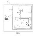
In accordance with one embodiment, a laser cutting apparatus 70 is provided for cutting prosthetic segments from source material 90. With reference specifically to FIG. 6 , the laser cutting apparatus 70 comprises a laser system 72 and a computer 74. The laser system 72 comprises a laser tube assembly 76, a motion system 78 and a support platform 80. The laser tube assembly 76 is configured to create a laser beam 82 which is directed through a series of optic elements such as mirrors 84 and lenses 86 in order to direct a focused laser beam 88 on the support platform 80, which is configured to support the source material 90. The focused laser beam 88 is configured to cut through the source material 90 in order to cut out a segment according to a prescribed pattern.
The motion system 78 preferably is arranged to selectively locate and move the position of the focused laser beam 88 relative to the platform 80 in order to cut the segment out of the source material 90. In the illustrated embodiment, the motion system 78 can move the laser beam's position along horizontal X and Y axes. The support platform 80 is vertically movable along a vertical Z axis. It is to be understood that, in other embodiments, other types of motion systems can be employed.
The computer 74 preferably controls the laser system 72 via a printer driver 92, which communicates data from the computer 74 to the laser system 72 in order to control laser parameters and motion. In the illustrated embodiment, a computer assisted design (CAD) software program, such as Corel Draw®, is hosted by the computer 74. The CAD software is used to create designs of segments that will be cut. FIG. 7 shows a cutting pattern or template 96 created by CAD software. The template 96 functions as a target for the laser. The illustrated template 96 is configured so that four valve leaflets will be cut from a sheet 98 of source material.
In a preferred embodiment, the CAD software also functions as a command interface for submitting cutting patterns 96 to the laser system 72 through the printer driver 92. When directed to do so by the computer 74 and printer driver 92, the laser system 72 precisely cuts the patterns 96 from the source material 90.
The laser cutting apparatus 70 is configured to have a pulse power, cutting speed, and number of pulses per inch that will impart sufficient energy to vaporize portions of the source material along a cut line in order to cut the desired segment shape, and to at least partially melt the cut edges. Melting the cut edges effectively fuses or welds the layers and fibrous matter together.
Welding of the edges is especially advantageous for laminar materials such as pericardium, because the melted edge resists delamination. FIG. 8 is a scanning electron microscope image taken along a cut edge 100 of a sample of equine pericardial tissue that has been cut using a laser. When compared with FIG. 5 , FIG. 8 shows that the characteristics of the laser-cut edge 100 are much different than the a razor-cut edge 66. As shown in FIG. 8 , the visceral, serosa and parietal layers are no longer distinguishable when the material has been laser cut. Additionally, the generally fibrous, layered character of the pericardium has been changed along the cut edge 100. Applicant has found that heart valve leaflets with melted edges exhibit dramatically increased durability over leaflets that have been cut using more traditional die-cutting or razor-cutting methods.
An issue that arises during laser cutting is management of thermal energy. Excessive thermal energy absorbed by a source material such as pericardium can burn the material. Burning of the material can result in several types of damage. For example, the burned material can become stiff and brittle or can become biased to bend in a particular direction. Further characteristics of burning include discoloration or even charring of the material.
Burned portions of a segment of material can jeopardize the integrity and durability of the entire segment, and of a prosthesis constructed using that segment. For example, a stiffened or biased portion of a prosthetic heart valve leaflet will not move in the same manner as the rest of the leaflet during opening and closure of the valve. The hemodynamic performance of the valve thus could be compromised. Further, damage caused by burning of the material generally weakens the material and could reduce the durability of the valve. As such, it is desirable to weld the material at the cut edge, but avoid communicating thermal energy into the cut segment beyond the edge.
Excessive burning of the laser cut edge can also have a negative impact. If excessive laser energy is applied to the cut edge, it is more likely that thermal energy will be conducted beyond the edge and into the segment, resulting in tissue necrosis. Additionally, the tissue at an excessively-burned edge may have a somewhat inconsistent thickness, having portions that are significantly thicker than other portions or developing beads of melted material. Discoloration of the cut edge can indicate application of excessive thermal energy. Inconsistencies in the edge make the segment more difficult to work with during manufacture and can affect performance of the segment. As such, it is desirable to weld the material at the cut edge in a manner so that the melted edge is relatively uniform in thickness and consistency and exhibits minimal, if any, beading.
In a preferred embodiment, a CO2 laser is used to laser cut heart valve leaflets out of a sheet of equine pericardial tissue about 0.35-0.55 mm thick. The laser system preferably is an M-series laser engraving and cutting system available from Universal Laser Systems, Inc. This device employs a 30 watt, pulsed, sealed CO2 laser. The CO2 laser produces laser light with a characteristic wavelength of 10.6 μm. Most non-metals, including equine pericardial tissue, are highly absorptive of laser energy at this wavelength, and also exhibit low thermal conductivity to such laser energy. Hence, the CO2 laser is especially advantageous for cutting pericardial tissue because the tissue absorbs and is vaporized by the CO2 laser light but very little or no thermal energy is conducted to regions of the tissue that are not being cut. Only the boundary/edge of the cut is melted, effectively forming a weld.
In the preferred embodiment, a sheet of equine pericardium is placed on the support surface 80. An operator directs the computer 74 to actuate the laser system 72, which cuts leaflets out of the sheet according to the prescribed pattern 96. To help maintain the tissue in good condition, it preferably is kept moist when being cut.
When cutting equine pericardium, the laser preferably is operated at a power of about 7.5 watts (joules/second). The laser can cut at a linear speed of about 1 inch per second, a pulse rate of about 1000 pulses per inch (PPI), and a laser spot diameter of about 0.003 inches.
A measurement of laser energy per pulse is computed by using the following equation (1):
[laser energy per pulse (joules/pulse)]=[power (joules/second)]/([cutting speed (inches/second)]×[pulse rate (pulses/inch)]).
[laser energy per pulse (joules/pulse)]=[power (joules/second)]/([cutting speed (inches/second)]×[pulse rate (pulses/inch)]).
For the above embodiment, the laser energy per pulse is about:
(7.5 joules/second)/((1 inch/second)×(1000 pulses/inch))=0.0075 joules/pulse.
(7.5 joules/second)/((1 inch/second)×(1000 pulses/inch))=0.0075 joules/pulse.
Other materials, such as bovine or other kinds of pericardium tissues and laminar materials can also be advantageously laser cut with a CO2 laser as discussed above. In another preferred embodiment wherein such materials, including equine pericardium, are laser cut, about 0.005-0.5 joules of laser energy are supplied per pulse, with a laser spot size of about 0.002 to 0.005 inches in diameter, a cutting speed of about 1 inch/second, and a pulse rate of about 1000 PPI. More preferably, about 0.005-0.02 joules of laser energy are supplied per pulse. For the Universal Laser Systems M-series laser discussed above, the following sample settings enable laser cutting within the above-discussed parameters: a 1.5 Lens, 20% power setting, 3.4% speed, 1000 PPI and 1000 dots per inch.
It is to be understood that if parameters such as the pulse rate and cutting speed are adjusted, corresponding adjustments to other parameters can be made so that the energy imparted to the material substantially stays within the desired parameters. In this manner, a generally uniform weld can be formed along a cut edge without discoloring the edge or imparting excessive heat to other portions of the segment.
It is also to be understood that other types of lasers, such as an erbium laser that generates a laser beam having a wavelength of about 2.7-3.0 μm, can suitably be used to cut segments. Such alternative lasers can be operated at settings so that the cut edges are welded as discussed above.
Alternative techniques may be employed for laser cutting of segments for use in prosthetics, such as disclosed in U.S. Patent Application Publication No. U.S. 2002/0091441, which was published on Jul. 11, 2002. The entire disclosure of this publication is hereby incorporated herein by reference.
Various types of tissue and man-made materials can be cut with a laser by using generally the same principles as discussed above. For example, other types of laminar tissue can be cut so that the cut edges are welded and have a generally uniform consistency with little or no discoloration. Similarly, for man-made materials such as woven or knitted polymers, the cut edges preferably are melted so that fraying of the woven filaments or yarns is minimized or avoided, but discoloration is also avoided.
With reference next to FIG. 9 , an embodiment of a laser cutting apparatus for cutting curved or tubular materials is illustrated. This embodiment is substantially similar to the embodiment presented in FIG. 6 except that the support surface 80 comprises a rotary axis 104 configured to accept a tubular source material 106. In addition to vertical movement about a Z-axis, the rotary axis 104 is adapted to rotate in order to help position the tubular source material 106 in an advantageous cutting position relative to the focused laser beam 88.
Although this invention has been disclosed in the context of certain preferred embodiments and examples, it will be understood by those skilled in the art that the present invention extends beyond the specifically disclosed embodiments to other alternative embodiments and/or uses of the invention and obvious modifications and equivalents thereof. In addition, while a number of variations of the invention have been shown and described in detail, other modifications, which are within the scope of this invention, will be readily apparent to those of skill in the art based upon this disclosure. It is also contemplated that various combinations or subcombinations of the specific features and aspects of the embodiments may be made and still fall within the scope of the invention. Accordingly, it should be understood that various features and aspects of the disclosed embodiments can be combined with or substituted for one another in order to form varying modes of the disclosed invention. Thus, it is intended that the scope of the present invention herein disclosed should not be limited by the particular disclosed embodiments described above, but should be determined only by a fair reading of the claims that follow.
Claims (9)
1. A method of creating an implantable medical prosthesis, comprising:
providing a sheet of pericardium, wherein the pericardium has at least two tissue layers;
cutting a segment of tissue out of the sheet of pericardium with a laser beam;
said cutting comprising operating a laser at a power and pulse rate such that said beam welds the layers of the pericardium together along a laser cut edge;
wherein the laser is operated in a pulsed manner, supplying between about 0.005-0.5 joules of laser energy per pulse, with a laser spot size of about 0.002-0.005 inches in diameter, thereby producing a laser cut edge without significantly burning the pericardium adjacent the cut edge.
2. The method of claim 1 , wherein the pericardium tissue comprises equine pericardium.
3. The method of claim 1 , wherein the laser beam power and pulse rate are selected so that there is substantially no discoloration of the pericardium along the cut edge.
4. The method of claim 1 , wherein the prosthesis comprises a heart valve, said cutting comprising cutting a plurality of segments of tissue out of the sheet of pericardium with the laser beam and attaching the cut segments to one another to form the valve.
5. The method of claim 1 , comprising moving the laser beam at a cutting speed of about 1 inch per second and a pulse rate of about 1000 pulses per inch.
6. The method of claim 5 , wherein the laser beam supplies between about 0.005-0.02 joules of laser energy per pulse.
7. The method of claim 1 , wherein the laser beam operates at a wavelength of about 10.6 microns.
8. The method of claim 1 , wherein the laser beam operates at a wavelength of about 2.7-3.0 microns.
9. The method of claim 1 , wherein the laser energy is about 0.0075 joules per pulse and a laser spot diameter of about 0.003 inches.
Priority Applications (1)
| Application Number | Priority Date | Filing Date | Title |
|---|---|---|---|
| US12/765,356 USRE42857E1 (en) | 2000-01-27 | 2010-04-22 | Method of laser cutting pericardial tissue for use with an implantable medical device |
Applications Claiming Priority (5)
| Application Number | Priority Date | Filing Date | Title |
|---|---|---|---|
| US17833300P | 2000-01-27 | 2000-01-27 | |
| US09/772,526 US6682559B2 (en) | 2000-01-27 | 2001-01-29 | Prosthetic heart valve |
| US30826801P | 2001-07-26 | 2001-07-26 | |
| US10/207,438 US6872226B2 (en) | 2001-01-29 | 2002-07-26 | Method of cutting material for use in implantable medical device |
| US12/765,356 USRE42857E1 (en) | 2000-01-27 | 2010-04-22 | Method of laser cutting pericardial tissue for use with an implantable medical device |
Related Parent Applications (1)
| Application Number | Title | Priority Date | Filing Date |
|---|---|---|---|
| US10/207,438 Reissue US6872226B2 (en) | 2000-01-27 | 2002-07-26 | Method of cutting material for use in implantable medical device |
Publications (1)
| Publication Number | Publication Date |
|---|---|
| USRE42857E1 true USRE42857E1 (en) | 2011-10-18 |
Family
ID=34555213
Family Applications (7)
| Application Number | Title | Priority Date | Filing Date |
|---|---|---|---|
| US10/207,438 Ceased US6872226B2 (en) | 2000-01-27 | 2002-07-26 | Method of cutting material for use in implantable medical device |
| US11/007,732 Ceased US7594974B2 (en) | 2000-01-27 | 2004-12-08 | Method of cutting material for use in implantable medical device |
| US12/370,787 Abandoned US20090188900A1 (en) | 2000-01-27 | 2009-02-13 | Method of cutting material for use in implantable medical device |
| US12/548,536 Expired - Fee Related US8043450B2 (en) | 2000-01-27 | 2009-08-27 | Method of cutting tissue using a laser |
| US12/765,356 Expired - Lifetime USRE42857E1 (en) | 2000-01-27 | 2010-04-22 | Method of laser cutting pericardial tissue for use with an implantable medical device |
| US12/765,449 Active 2024-10-31 USRE42818E1 (en) | 2000-01-27 | 2010-04-22 | Method of cutting material for use in implantable medical device |
| US13/279,754 Expired - Lifetime US8672999B2 (en) | 2000-01-27 | 2011-10-24 | Prosthetic heart valve assemblies |
Family Applications Before (4)
| Application Number | Title | Priority Date | Filing Date |
|---|---|---|---|
| US10/207,438 Ceased US6872226B2 (en) | 2000-01-27 | 2002-07-26 | Method of cutting material for use in implantable medical device |
| US11/007,732 Ceased US7594974B2 (en) | 2000-01-27 | 2004-12-08 | Method of cutting material for use in implantable medical device |
| US12/370,787 Abandoned US20090188900A1 (en) | 2000-01-27 | 2009-02-13 | Method of cutting material for use in implantable medical device |
| US12/548,536 Expired - Fee Related US8043450B2 (en) | 2000-01-27 | 2009-08-27 | Method of cutting tissue using a laser |
Family Applications After (2)
| Application Number | Title | Priority Date | Filing Date |
|---|---|---|---|
| US12/765,449 Active 2024-10-31 USRE42818E1 (en) | 2000-01-27 | 2010-04-22 | Method of cutting material for use in implantable medical device |
| US13/279,754 Expired - Lifetime US8672999B2 (en) | 2000-01-27 | 2011-10-24 | Prosthetic heart valve assemblies |
Country Status (1)
| Country | Link |
|---|---|
| US (7) | US6872226B2 (en) |
Cited By (12)
| Publication number | Priority date | Publication date | Assignee | Title |
|---|---|---|---|---|
| US20120004499A1 (en) * | 2010-07-01 | 2012-01-05 | Lexion Medical, Llc | Surgical Method for Performing a Coronary Blood Vessel Bypass |
| US8764818B2 (en) | 2011-07-20 | 2014-07-01 | Boston Scientific Scimed, Inc. | Heart valve replacement |
| US9744031B2 (en) | 2010-05-25 | 2017-08-29 | Jenavalve Technology, Inc. | Prosthetic heart valve and endoprosthesis comprising a prosthetic heart valve and a stent |
| US10993805B2 (en) | 2008-02-26 | 2021-05-04 | Jenavalve Technology, Inc. | Stent for the positioning and anchoring of a valvular prosthesis in an implantation site in the heart of a patient |
| US11065138B2 (en) | 2016-05-13 | 2021-07-20 | Jenavalve Technology, Inc. | Heart valve prosthesis delivery system and method for delivery of heart valve prosthesis with introducer sheath and loading system |
| US11185405B2 (en) | 2013-08-30 | 2021-11-30 | Jenavalve Technology, Inc. | Radially collapsible frame for a prosthetic valve and method for manufacturing such a frame |
| US11197754B2 (en) | 2017-01-27 | 2021-12-14 | Jenavalve Technology, Inc. | Heart valve mimicry |
| US11337800B2 (en) | 2015-05-01 | 2022-05-24 | Jenavalve Technology, Inc. | Device and method with reduced pacemaker rate in heart valve replacement |
| US11337799B2 (en) | 2017-02-23 | 2022-05-24 | University of Pittsburgh—of the Commonwealth System of Higher Education | Stentless biopolymer heart valve replacement capable of living tissue regeneration |
| US11357624B2 (en) | 2007-04-13 | 2022-06-14 | Jenavalve Technology, Inc. | Medical device for treating a heart valve insufficiency |
| US11517431B2 (en) | 2005-01-20 | 2022-12-06 | Jenavalve Technology, Inc. | Catheter system for implantation of prosthetic heart valves |
| US11564794B2 (en) | 2008-02-26 | 2023-01-31 | Jenavalve Technology, Inc. | Stent for the positioning and anchoring of a valvular prosthesis in an implantation site in the heart of a patient |
Families Citing this family (267)
| Publication number | Priority date | Publication date | Assignee | Title |
|---|---|---|---|---|
| US6006134A (en) * | 1998-04-30 | 1999-12-21 | Medtronic, Inc. | Method and device for electronically controlling the beating of a heart using venous electrical stimulation of nerve fibers |
| US6254564B1 (en) | 1998-09-10 | 2001-07-03 | Percardia, Inc. | Left ventricular conduit with blood vessel graft |
| US6214054B1 (en) | 1998-09-21 | 2001-04-10 | Edwards Lifesciences Corporation | Method for fixation of biological tissues having mitigated propensity for post-implantation calcification and thrombosis and bioprosthetic devices prepared thereby |
| US8579966B2 (en) | 1999-11-17 | 2013-11-12 | Medtronic Corevalve Llc | Prosthetic valve for transluminal delivery |
| US20070043435A1 (en) * | 1999-11-17 | 2007-02-22 | Jacques Seguin | Non-cylindrical prosthetic valve system for transluminal delivery |
| US7018406B2 (en) * | 1999-11-17 | 2006-03-28 | Corevalve Sa | Prosthetic valve for transluminal delivery |
| US8016877B2 (en) * | 1999-11-17 | 2011-09-13 | Medtronic Corevalve Llc | Prosthetic valve for transluminal delivery |
| US8241274B2 (en) | 2000-01-19 | 2012-08-14 | Medtronic, Inc. | Method for guiding a medical device |
| US7749245B2 (en) | 2000-01-27 | 2010-07-06 | Medtronic, Inc. | Cardiac valve procedure methods and devices |
| US6769434B2 (en) * | 2000-06-30 | 2004-08-03 | Viacor, Inc. | Method and apparatus for performing a procedure on a cardiac valve |
| US6872226B2 (en) * | 2001-01-29 | 2005-03-29 | 3F Therapeutics, Inc. | Method of cutting material for use in implantable medical device |
| US6692513B2 (en) | 2000-06-30 | 2004-02-17 | Viacor, Inc. | Intravascular filter with debris entrapment mechanism |
| DE10010074B4 (en) | 2000-02-28 | 2005-04-14 | Fraunhofer-Gesellschaft zur Förderung der angewandten Forschung e.V. | Device for fastening and anchoring heart valve prostheses |
| DE10010073B4 (en) * | 2000-02-28 | 2005-12-22 | Fraunhofer-Gesellschaft zur Förderung der angewandten Forschung e.V. | Anchoring for implantable heart valve prostheses |
| ATE396648T1 (en) * | 2000-05-09 | 2008-06-15 | Paieon Inc | SYSTEM AND METHOD FOR THREE-DIMENTIONAL RECONSTRUCTION OF AN ARTERY |
| IL154433A0 (en) | 2000-08-18 | 2003-09-17 | Atritech Inc | Expandable implant devices for filtering blood flow from atrial appendages |
| US6602286B1 (en) | 2000-10-26 | 2003-08-05 | Ernst Peter Strecker | Implantable valve system |
| US8623077B2 (en) | 2001-06-29 | 2014-01-07 | Medtronic, Inc. | Apparatus for replacing a cardiac valve |
| US7544206B2 (en) * | 2001-06-29 | 2009-06-09 | Medtronic, Inc. | Method and apparatus for resecting and replacing an aortic valve |
| US8771302B2 (en) | 2001-06-29 | 2014-07-08 | Medtronic, Inc. | Method and apparatus for resecting and replacing an aortic valve |
| FR2826863B1 (en) * | 2001-07-04 | 2003-09-26 | Jacques Seguin | ASSEMBLY FOR PLACING A PROSTHETIC VALVE IN A BODY CONDUIT |
| FR2828091B1 (en) | 2001-07-31 | 2003-11-21 | Seguin Jacques | ASSEMBLY ALLOWING THE PLACEMENT OF A PROTHETIC VALVE IN A BODY DUCT |
| FR2828263B1 (en) | 2001-08-03 | 2007-05-11 | Philipp Bonhoeffer | DEVICE FOR IMPLANTATION OF AN IMPLANT AND METHOD FOR IMPLANTATION OF THE DEVICE |
| US7097659B2 (en) * | 2001-09-07 | 2006-08-29 | Medtronic, Inc. | Fixation band for affixing a prosthetic heart valve to tissue |
| US7201771B2 (en) | 2001-12-27 | 2007-04-10 | Arbor Surgical Technologies, Inc. | Bioprosthetic heart valve |
| US6878168B2 (en) | 2002-01-03 | 2005-04-12 | Edwards Lifesciences Corporation | Treatment of bioprosthetic tissues to mitigate post implantation calcification |
| US6752828B2 (en) | 2002-04-03 | 2004-06-22 | Scimed Life Systems, Inc. | Artificial valve |
| US8721713B2 (en) * | 2002-04-23 | 2014-05-13 | Medtronic, Inc. | System for implanting a replacement valve |
| US7959674B2 (en) | 2002-07-16 | 2011-06-14 | Medtronic, Inc. | Suture locking assembly and method of use |
| CO5500017A1 (en) * | 2002-09-23 | 2005-03-31 | 3F Therapeutics Inc | MITRAL PROTESTIC VALVE |
| AU2003285943B2 (en) | 2002-10-24 | 2008-08-21 | Boston Scientific Limited | Venous valve apparatus and method |
| US8551162B2 (en) | 2002-12-20 | 2013-10-08 | Medtronic, Inc. | Biologically implantable prosthesis |
| US6945957B2 (en) * | 2002-12-30 | 2005-09-20 | Scimed Life Systems, Inc. | Valve treatment catheter and methods |
| US7393339B2 (en) * | 2003-02-21 | 2008-07-01 | C. R. Bard, Inc. | Multi-lumen catheter with separate distal tips |
| US8021421B2 (en) | 2003-08-22 | 2011-09-20 | Medtronic, Inc. | Prosthesis heart valve fixturing device |
| US9579194B2 (en) * | 2003-10-06 | 2017-02-28 | Medtronic ATS Medical, Inc. | Anchoring structure with concave landing zone |
| US7556647B2 (en) | 2003-10-08 | 2009-07-07 | Arbor Surgical Technologies, Inc. | Attachment device and methods of using the same |
| WO2005043122A2 (en) * | 2003-10-29 | 2005-05-12 | Warwick Mills, Inc. | Carrier fiber assembly for tissue structures |
| US7186265B2 (en) * | 2003-12-10 | 2007-03-06 | Medtronic, Inc. | Prosthetic cardiac valves and systems and methods for implanting thereof |
| US7854761B2 (en) | 2003-12-19 | 2010-12-21 | Boston Scientific Scimed, Inc. | Methods for venous valve replacement with a catheter |
| US8128681B2 (en) * | 2003-12-19 | 2012-03-06 | Boston Scientific Scimed, Inc. | Venous valve apparatus, system, and method |
| US9005273B2 (en) | 2003-12-23 | 2015-04-14 | Sadra Medical, Inc. | Assessing the location and performance of replacement heart valves |
| US7329279B2 (en) | 2003-12-23 | 2008-02-12 | Sadra Medical, Inc. | Methods and apparatus for endovascularly replacing a patient's heart valve |
| US7959666B2 (en) * | 2003-12-23 | 2011-06-14 | Sadra Medical, Inc. | Methods and apparatus for endovascularly replacing a heart valve |
| US20050137696A1 (en) * | 2003-12-23 | 2005-06-23 | Sadra Medical | Apparatus and methods for protecting against embolization during endovascular heart valve replacement |
| US7780725B2 (en) | 2004-06-16 | 2010-08-24 | Sadra Medical, Inc. | Everting heart valve |
| US7824442B2 (en) | 2003-12-23 | 2010-11-02 | Sadra Medical, Inc. | Methods and apparatus for endovascularly replacing a heart valve |
| US7748389B2 (en) * | 2003-12-23 | 2010-07-06 | Sadra Medical, Inc. | Leaflet engagement elements and methods for use thereof |
| US7445631B2 (en) * | 2003-12-23 | 2008-11-04 | Sadra Medical, Inc. | Methods and apparatus for endovascularly replacing a patient's heart valve |
| US20050137694A1 (en) | 2003-12-23 | 2005-06-23 | Haug Ulrich R. | Methods and apparatus for endovascularly replacing a patient's heart valve |
| US9526609B2 (en) | 2003-12-23 | 2016-12-27 | Boston Scientific Scimed, Inc. | Methods and apparatus for endovascularly replacing a patient's heart valve |
| US8343213B2 (en) | 2003-12-23 | 2013-01-01 | Sadra Medical, Inc. | Leaflet engagement elements and methods for use thereof |
| US8182528B2 (en) | 2003-12-23 | 2012-05-22 | Sadra Medical, Inc. | Locking heart valve anchor |
| EP2526895B1 (en) | 2003-12-23 | 2014-01-29 | Sadra Medical, Inc. | Repositionable heart valve |
| US8287584B2 (en) | 2005-11-14 | 2012-10-16 | Sadra Medical, Inc. | Medical implant deployment tool |
| US8603160B2 (en) | 2003-12-23 | 2013-12-10 | Sadra Medical, Inc. | Method of using a retrievable heart valve anchor with a sheath |
| US20050137687A1 (en) | 2003-12-23 | 2005-06-23 | Sadra Medical | Heart valve anchor and method |
| US7381219B2 (en) * | 2003-12-23 | 2008-06-03 | Sadra Medical, Inc. | Low profile heart valve and delivery system |
| US8840663B2 (en) | 2003-12-23 | 2014-09-23 | Sadra Medical, Inc. | Repositionable heart valve method |
| US20050137691A1 (en) * | 2003-12-23 | 2005-06-23 | Sadra Medical | Two piece heart valve and anchor |
| US11278398B2 (en) | 2003-12-23 | 2022-03-22 | Boston Scientific Scimed, Inc. | Methods and apparatus for endovascular heart valve replacement comprising tissue grasping elements |
| US8579962B2 (en) | 2003-12-23 | 2013-11-12 | Sadra Medical, Inc. | Methods and apparatus for performing valvuloplasty |
| US20050137686A1 (en) * | 2003-12-23 | 2005-06-23 | Sadra Medical, A Delaware Corporation | Externally expandable heart valve anchor and method |
| US8052749B2 (en) | 2003-12-23 | 2011-11-08 | Sadra Medical, Inc. | Methods and apparatus for endovascular heart valve replacement comprising tissue grasping elements |
| US20120041550A1 (en) | 2003-12-23 | 2012-02-16 | Sadra Medical, Inc. | Methods and Apparatus for Endovascular Heart Valve Replacement Comprising Tissue Grasping Elements |
| US7824443B2 (en) | 2003-12-23 | 2010-11-02 | Sadra Medical, Inc. | Medical implant delivery and deployment tool |
| ITTO20040135A1 (en) | 2004-03-03 | 2004-06-03 | Sorin Biomedica Cardio Spa | CARDIAC VALVE PROSTHESIS |
| JP5290573B2 (en) | 2004-04-23 | 2013-09-18 | メドトロニック スリーエフ セラピューティクス,インコーポレイティド | Implantable prosthetic valve |
| US7566343B2 (en) | 2004-09-02 | 2009-07-28 | Boston Scientific Scimed, Inc. | Cardiac valve, system, and method |
| US20060052867A1 (en) | 2004-09-07 | 2006-03-09 | Medtronic, Inc | Replacement prosthetic heart valve, system and method of implant |
| KR20070094888A (en) * | 2004-11-19 | 2007-09-27 | 메드트로닉 인코포레이티드 | Method and apparatus for treatment of cardiac valves |
| US8562672B2 (en) | 2004-11-19 | 2013-10-22 | Medtronic, Inc. | Apparatus for treatment of cardiac valves and method of its manufacture |
| US20060173490A1 (en) | 2005-02-01 | 2006-08-03 | Boston Scientific Scimed, Inc. | Filter system and method |
| US7854755B2 (en) * | 2005-02-01 | 2010-12-21 | Boston Scientific Scimed, Inc. | Vascular catheter, system, and method |
| US7878966B2 (en) * | 2005-02-04 | 2011-02-01 | Boston Scientific Scimed, Inc. | Ventricular assist and support device |
| US7670368B2 (en) | 2005-02-07 | 2010-03-02 | Boston Scientific Scimed, Inc. | Venous valve apparatus, system, and method |
| US7780722B2 (en) | 2005-02-07 | 2010-08-24 | Boston Scientific Scimed, Inc. | Venous valve apparatus, system, and method |
| ITTO20050074A1 (en) | 2005-02-10 | 2006-08-11 | Sorin Biomedica Cardio Srl | CARDIAC VALVE PROSTHESIS |
| US7867274B2 (en) | 2005-02-23 | 2011-01-11 | Boston Scientific Scimed, Inc. | Valve apparatus, system and method |
| US7513909B2 (en) | 2005-04-08 | 2009-04-07 | Arbor Surgical Technologies, Inc. | Two-piece prosthetic valves with snap-in connection and methods for use |
| US7722666B2 (en) | 2005-04-15 | 2010-05-25 | Boston Scientific Scimed, Inc. | Valve apparatus, system and method |
| US7962208B2 (en) | 2005-04-25 | 2011-06-14 | Cardiac Pacemakers, Inc. | Method and apparatus for pacing during revascularization |
| US7914569B2 (en) | 2005-05-13 | 2011-03-29 | Medtronics Corevalve Llc | Heart valve prosthesis and methods of manufacture and use |
| US8211169B2 (en) | 2005-05-27 | 2012-07-03 | Medtronic, Inc. | Gasket with collar for prosthetic heart valves and methods for using them |
| US7238200B2 (en) | 2005-06-03 | 2007-07-03 | Arbor Surgical Technologies, Inc. | Apparatus and methods for making leaflets and valve prostheses including such leaflets |
| US8012198B2 (en) | 2005-06-10 | 2011-09-06 | Boston Scientific Scimed, Inc. | Venous valve, system, and method |
| ATE389497T1 (en) * | 2005-06-21 | 2008-04-15 | Fameccanica Data Spa | DEVICE AND DEVICE FOR LASER CUTTING ARTICLES, IN PARTICULAR SANITARY PRODUCTS AND THEIR COMPONENTS, WITH A LASER FOCUS POINT DIAMETER OF 0.1 TO 0.3 MM |
| US11751873B2 (en) | 2005-07-26 | 2023-09-12 | Cilag Gmbh International | Electrically powered surgical instrument with manual release |
| US9554803B2 (en) | 2005-07-26 | 2017-01-31 | Ethicon Endo-Surgery, Llc | Electrically self-powered surgical instrument with manual release |
| US8573462B2 (en) | 2006-05-19 | 2013-11-05 | Ethicon Endo-Surgery, Inc. | Electrical surgical instrument with optimized power supply and drive |
| US10314583B2 (en) | 2005-07-26 | 2019-06-11 | Ethicon Llc | Electrically self-powered surgical instrument with manual release |
| US9662116B2 (en) | 2006-05-19 | 2017-05-30 | Ethicon, Llc | Electrically self-powered surgical instrument with cryptographic identification of interchangeable part |
| US8627995B2 (en) | 2006-05-19 | 2014-01-14 | Ethicon Endo-Sugery, Inc. | Electrically self-powered surgical instrument with cryptographic identification of interchangeable part |
| US7712606B2 (en) | 2005-09-13 | 2010-05-11 | Sadra Medical, Inc. | Two-part package for medical implant |
| US7569071B2 (en) | 2005-09-21 | 2009-08-04 | Boston Scientific Scimed, Inc. | Venous valve, system, and method with sinus pocket |
| US7682304B2 (en) * | 2005-09-21 | 2010-03-23 | Medtronic, Inc. | Composite heart valve apparatus manufactured using techniques involving laser machining of tissue |
| EP1945142B1 (en) | 2005-09-26 | 2013-12-25 | Medtronic, Inc. | Prosthetic cardiac and venous valves |
| DE102005051849B4 (en) | 2005-10-28 | 2010-01-21 | JenaValve Technology Inc., Wilmington | Device for implantation and attachment of heart valve prostheses |
| DE102005052628B4 (en) * | 2005-11-04 | 2014-06-05 | Jenavalve Technology Inc. | Self-expanding, flexible wire mesh with integrated valvular prosthesis for the transvascular heart valve replacement and a system with such a device and a delivery catheter |
| US20070213813A1 (en) | 2005-12-22 | 2007-09-13 | Symetis Sa | Stent-valves for valve replacement and associated methods and systems for surgery |
| US9078781B2 (en) * | 2006-01-11 | 2015-07-14 | Medtronic, Inc. | Sterile cover for compressible stents used in percutaneous device delivery systems |
| US7799038B2 (en) | 2006-01-20 | 2010-09-21 | Boston Scientific Scimed, Inc. | Translumenal apparatus, system, and method |
| US7967857B2 (en) | 2006-01-27 | 2011-06-28 | Medtronic, Inc. | Gasket with spring collar for prosthetic heart valves and methods for making and using them |
| EP1988851A2 (en) | 2006-02-14 | 2008-11-12 | Sadra Medical, Inc. | Systems and methods for delivering a medical implant |
| US20080275550A1 (en) * | 2006-02-24 | 2008-11-06 | Arash Kheradvar | Implantable small percutaneous valve and methods of delivery |
| EP2004095B1 (en) | 2006-03-28 | 2019-06-12 | Medtronic, Inc. | Prosthetic cardiac valve formed from pericardium material and methods of making same |
| US7615128B2 (en) * | 2006-04-05 | 2009-11-10 | Mikkelsen Graphic Engineering, Inc. | Method and apparatus for fray-free textile cutting |
| WO2007117562A2 (en) * | 2006-04-05 | 2007-10-18 | Mikkelsen Graphic Engineering, Inc. | Method and apparatus for fray-free textile cutting |
| US7524331B2 (en) * | 2006-04-06 | 2009-04-28 | Medtronic Vascular, Inc. | Catheter delivered valve having a barrier to provide an enhanced seal |
| US7740655B2 (en) * | 2006-04-06 | 2010-06-22 | Medtronic Vascular, Inc. | Reinforced surgical conduit for implantation of a stented valve therein |
| US20070239269A1 (en) * | 2006-04-07 | 2007-10-11 | Medtronic Vascular, Inc. | Stented Valve Having Dull Struts |
| US20070244544A1 (en) * | 2006-04-14 | 2007-10-18 | Medtronic Vascular, Inc. | Seal for Enhanced Stented Valve Fixation |
| US20070244545A1 (en) * | 2006-04-14 | 2007-10-18 | Medtronic Vascular, Inc. | Prosthetic Conduit With Radiopaque Symmetry Indicators |
| US20070244546A1 (en) * | 2006-04-18 | 2007-10-18 | Medtronic Vascular, Inc. | Stent Foundation for Placement of a Stented Valve |
| WO2007130881A2 (en) | 2006-04-29 | 2007-11-15 | Arbor Surgical Technologies, Inc. | Multiple component prosthetic heart valve assemblies and apparatus and methods for delivering them |
| US11304800B2 (en) | 2006-09-19 | 2022-04-19 | Medtronic Ventor Technologies Ltd. | Sinus-engaging valve fixation member |
| US8876895B2 (en) | 2006-09-19 | 2014-11-04 | Medtronic Ventor Technologies Ltd. | Valve fixation member having engagement arms |
| US8834564B2 (en) * | 2006-09-19 | 2014-09-16 | Medtronic, Inc. | Sinus-engaging valve fixation member |
| WO2008047354A2 (en) | 2006-10-16 | 2008-04-24 | Ventor Technologies Ltd. | Transapical delivery system with ventriculo-arterial overflow bypass |
| EP2077718B2 (en) | 2006-10-27 | 2022-03-09 | Edwards Lifesciences Corporation | Biological tissue for surgical implantation |
| WO2008070797A2 (en) | 2006-12-06 | 2008-06-12 | Medtronic Corevalve, Inc. | System and method for transapical delivery of an annulus anchored self-expanding valve |
| WO2008091493A1 (en) | 2007-01-08 | 2008-07-31 | California Institute Of Technology | In-situ formation of a valve |
| JP5313928B2 (en) | 2007-02-05 | 2013-10-09 | ボストン サイエンティフィック リミテッド | Percutaneous valves and systems |
| US20080195230A1 (en) * | 2007-02-09 | 2008-08-14 | Quijano Rodolfo C | Pericardial tissue sheet |
| US20080262593A1 (en) * | 2007-02-15 | 2008-10-23 | Ryan Timothy R | Multi-layered stents and methods of implanting |
| WO2008103295A2 (en) * | 2007-02-16 | 2008-08-28 | Medtronic, Inc. | Replacement prosthetic heart valves and methods of implantation |
| US9138315B2 (en) * | 2007-04-13 | 2015-09-22 | Jenavalve Technology Gmbh | Medical device for treating a heart valve insufficiency or stenosis |
| US9295551B2 (en) * | 2007-04-13 | 2016-03-29 | Jenavalve Technology Gmbh | Methods of implanting an endoprosthesis |
| FR2915087B1 (en) | 2007-04-20 | 2021-11-26 | Corevalve Inc | IMPLANT FOR TREATMENT OF A HEART VALVE, IN PARTICULAR OF A MITRAL VALVE, EQUIPMENT INCLUDING THIS IMPLANT AND MATERIAL FOR PLACING THIS IMPLANT. |
| US9101691B2 (en) | 2007-06-11 | 2015-08-11 | Edwards Lifesciences Corporation | Methods for pre-stressing and capping bioprosthetic tissue |
| DE202007009631U1 (en) * | 2007-07-04 | 2007-09-06 | Held Systems Ag | Device for cutting technical fabrics, in particular for airbags |
| US8828079B2 (en) | 2007-07-26 | 2014-09-09 | Boston Scientific Scimed, Inc. | Circulatory valve, system and method |
| US8747458B2 (en) * | 2007-08-20 | 2014-06-10 | Medtronic Ventor Technologies Ltd. | Stent loading tool and method for use thereof |
| US20090138079A1 (en) * | 2007-10-10 | 2009-05-28 | Vector Technologies Ltd. | Prosthetic heart valve for transfemoral delivery |
| US10856970B2 (en) | 2007-10-10 | 2020-12-08 | Medtronic Ventor Technologies Ltd. | Prosthetic heart valve for transfemoral delivery |
| US9848981B2 (en) | 2007-10-12 | 2017-12-26 | Mayo Foundation For Medical Education And Research | Expandable valve prosthesis with sealing mechanism |
| US7892276B2 (en) | 2007-12-21 | 2011-02-22 | Boston Scientific Scimed, Inc. | Valve with delayed leaflet deployment |
| US8357387B2 (en) | 2007-12-21 | 2013-01-22 | Edwards Lifesciences Corporation | Capping bioprosthetic tissue to reduce calcification |
| US9149358B2 (en) * | 2008-01-24 | 2015-10-06 | Medtronic, Inc. | Delivery systems for prosthetic heart valves |
| US9393115B2 (en) | 2008-01-24 | 2016-07-19 | Medtronic, Inc. | Delivery systems and methods of implantation for prosthetic heart valves |
| EP2254513B1 (en) * | 2008-01-24 | 2015-10-28 | Medtronic, Inc. | Stents for prosthetic heart valves |
| EP3572045B1 (en) | 2008-01-24 | 2022-12-21 | Medtronic, Inc. | Stents for prosthetic heart valves |
| US20090287290A1 (en) * | 2008-01-24 | 2009-11-19 | Medtronic, Inc. | Delivery Systems and Methods of Implantation for Prosthetic Heart Valves |
| WO2009094501A1 (en) | 2008-01-24 | 2009-07-30 | Medtronic, Inc. | Markers for prosthetic heart valves |
| US8157853B2 (en) * | 2008-01-24 | 2012-04-17 | Medtronic, Inc. | Delivery systems and methods of implantation for prosthetic heart valves |
| US8398704B2 (en) | 2008-02-26 | 2013-03-19 | Jenavalve Technology, Inc. | Stent for the positioning and anchoring of a valvular prosthesis in an implantation site in the heart of a patient |
| US8317858B2 (en) | 2008-02-26 | 2012-11-27 | Jenavalve Technology, Inc. | Stent for the positioning and anchoring of a valvular prosthesis in an implantation site in the heart of a patient |
| US8465540B2 (en) * | 2008-02-26 | 2013-06-18 | Jenavalve Technology, Inc. | Stent for the positioning and anchoring of a valvular prosthesis |
| US9168130B2 (en) | 2008-02-26 | 2015-10-27 | Jenavalve Technology Gmbh | Stent for the positioning and anchoring of a valvular prosthesis in an implantation site in the heart of a patient |
| US20090264989A1 (en) * | 2008-02-28 | 2009-10-22 | Philipp Bonhoeffer | Prosthetic heart valve systems |
| US8313525B2 (en) | 2008-03-18 | 2012-11-20 | Medtronic Ventor Technologies, Ltd. | Valve suturing and implantation procedures |
| US8430927B2 (en) * | 2008-04-08 | 2013-04-30 | Medtronic, Inc. | Multiple orifice implantable heart valve and methods of implantation |
| US8312825B2 (en) * | 2008-04-23 | 2012-11-20 | Medtronic, Inc. | Methods and apparatuses for assembly of a pericardial prosthetic heart valve |
| US8696743B2 (en) * | 2008-04-23 | 2014-04-15 | Medtronic, Inc. | Tissue attachment devices and methods for prosthetic heart valves |
| EP2119417B2 (en) | 2008-05-16 | 2020-04-29 | Sorin Group Italia S.r.l. | Atraumatic prosthetic heart valve prosthesis |
| US9039756B2 (en) | 2008-07-21 | 2015-05-26 | Jenesis Surgical, Llc | Repositionable endoluminal support structure and its applications |
| EP3878408A1 (en) | 2008-07-21 | 2021-09-15 | Jenesis Surgical, LLC | Endoluminal support apparatus |
| US8998981B2 (en) * | 2008-09-15 | 2015-04-07 | Medtronic, Inc. | Prosthetic heart valve having identifiers for aiding in radiographic positioning |
| US8721714B2 (en) | 2008-09-17 | 2014-05-13 | Medtronic Corevalve Llc | Delivery system for deployment of medical devices |
| CN102292053A (en) | 2008-09-29 | 2011-12-21 | 卡迪尔克阀门技术公司 | Heart valve |
| WO2010040009A1 (en) | 2008-10-01 | 2010-04-08 | Cardiaq Valve Technologies, Inc. | Delivery system for vascular implant |
| CA2739961A1 (en) | 2008-10-10 | 2010-04-15 | Sadra Medical, Inc. | Medical devices and delivery systems for delivering medical devices |
| US8137398B2 (en) * | 2008-10-13 | 2012-03-20 | Medtronic Ventor Technologies Ltd | Prosthetic valve having tapered tip when compressed for delivery |
| US8986361B2 (en) | 2008-10-17 | 2015-03-24 | Medtronic Corevalve, Inc. | Delivery system for deployment of medical devices |
| ES2551694T3 (en) | 2008-12-23 | 2015-11-23 | Sorin Group Italia S.R.L. | Expandable prosthetic valve with anchoring appendages |
| CA2961053C (en) | 2009-04-15 | 2019-04-30 | Edwards Lifesciences Cardiaq Llc | Vascular implant and delivery system |
| EP2246011B1 (en) | 2009-04-27 | 2014-09-03 | Sorin Group Italia S.r.l. | Prosthetic vascular conduit |
| US20100292779A1 (en) * | 2009-05-15 | 2010-11-18 | Helmut Straubinger | Device for compressing a stent and a system as well as a method for loading a stent into a medical delivery system |
| US8808369B2 (en) * | 2009-10-05 | 2014-08-19 | Mayo Foundation For Medical Education And Research | Minimally invasive aortic valve replacement |
| US9226826B2 (en) * | 2010-02-24 | 2016-01-05 | Medtronic, Inc. | Transcatheter valve structure and methods for valve delivery |
| NZ602706A (en) | 2010-03-23 | 2014-02-28 | Edwards Lifesciences Corp | Methods of conditioning sheet bioprosthetic tissue |
| CA2794750C (en) * | 2010-03-26 | 2015-06-16 | Thubrikar Aortic Valve, Inc. | Valve component, frame component and prosthetic valve device including the same for implantation in a body lumen |
| US8652204B2 (en) | 2010-04-01 | 2014-02-18 | Medtronic, Inc. | Transcatheter valve with torsion spring fixation and related systems and methods |
| US8579964B2 (en) | 2010-05-05 | 2013-11-12 | Neovasc Inc. | Transcatheter mitral valve prosthesis |
| US11278406B2 (en) | 2010-05-20 | 2022-03-22 | Jenavalve Technology, Inc. | Catheter system for introducing an expandable heart valve stent into the body of a patient, insertion system with a catheter system and medical device for treatment of a heart valve defect |
| US10856978B2 (en) | 2010-05-20 | 2020-12-08 | Jenavalve Technology, Inc. | Catheter system |
| IT1400327B1 (en) | 2010-05-21 | 2013-05-24 | Sorin Biomedica Cardio Srl | SUPPORT DEVICE FOR VALVULAR PROSTHESIS AND CORRESPONDING CORRESPONDENT. |
| US8906601B2 (en) | 2010-06-17 | 2014-12-09 | Edwardss Lifesciences Corporation | Methods for stabilizing a bioprosthetic tissue by chemical modification of antigenic carbohydrates |
| EP2409808A1 (en) * | 2010-07-22 | 2012-01-25 | Bystronic Laser AG | Laser processing machine |
| US9918833B2 (en) | 2010-09-01 | 2018-03-20 | Medtronic Vascular Galway | Prosthetic valve support structure |
| EP4119107A3 (en) | 2010-09-10 | 2023-02-15 | Boston Scientific Limited | Valve replacement devices, delivery device for a valve replacement device and method of production of a valve replacement device |
| US9351829B2 (en) | 2010-11-17 | 2016-05-31 | Edwards Lifesciences Corporation | Double cross-linkage process to enhance post-implantation bioprosthetic tissue durability |
| EP2486893B1 (en) | 2011-02-14 | 2017-07-05 | Sorin Group Italia S.r.l. | Sutureless anchoring device for cardiac valve prostheses |
| EP2486894B1 (en) | 2011-02-14 | 2021-06-09 | Sorin Group Italia S.r.l. | Sutureless anchoring device for cardiac valve prostheses |
| WO2012127309A1 (en) | 2011-03-21 | 2012-09-27 | Ontorfano Matteo | Disk-based valve apparatus and method for the treatment of valve dysfunction |
| US9308087B2 (en) | 2011-04-28 | 2016-04-12 | Neovasc Tiara Inc. | Sequentially deployed transcatheter mitral valve prosthesis |
| US9554897B2 (en) | 2011-04-28 | 2017-01-31 | Neovasc Tiara Inc. | Methods and apparatus for engaging a valve prosthesis with tissue |
| EP2520251A1 (en) | 2011-05-05 | 2012-11-07 | Symetis SA | Method and Apparatus for Compressing Stent-Valves |
| US9358107B2 (en) | 2011-06-30 | 2016-06-07 | Edwards Lifesciences Corporation | Systems, dies, and methods for processing pericardial tissue |
| WO2013009975A1 (en) | 2011-07-12 | 2013-01-17 | Boston Scientific Scimed, Inc. | Coupling system for medical devices |
| US9668859B2 (en) | 2011-08-05 | 2017-06-06 | California Institute Of Technology | Percutaneous heart valve delivery systems |
| JP6005168B2 (en) | 2011-10-21 | 2016-10-12 | イエナバルブ テクノロジー インク | Catheter system for introducing an expandable heart valve stent into a patient's body, insertion system equipped with a catheter system, and medical device for treating heart valve defects |
| US9131926B2 (en) | 2011-11-10 | 2015-09-15 | Boston Scientific Scimed, Inc. | Direct connect flush system |
| US8940014B2 (en) | 2011-11-15 | 2015-01-27 | Boston Scientific Scimed, Inc. | Bond between components of a medical device |
| US8951243B2 (en) | 2011-12-03 | 2015-02-10 | Boston Scientific Scimed, Inc. | Medical device handle |
| US9277993B2 (en) | 2011-12-20 | 2016-03-08 | Boston Scientific Scimed, Inc. | Medical device delivery systems |
| US9510945B2 (en) | 2011-12-20 | 2016-12-06 | Boston Scientific Scimed Inc. | Medical device handle |
| EP2842517A1 (en) | 2011-12-29 | 2015-03-04 | Sorin Group Italia S.r.l. | A kit for implanting prosthetic vascular conduits |
| US10172708B2 (en) | 2012-01-25 | 2019-01-08 | Boston Scientific Scimed, Inc. | Valve assembly with a bioabsorbable gasket and a replaceable valve implant |
| EP2849678B1 (en) | 2012-05-16 | 2022-08-10 | JenaValve Technology, Inc. | Catheter delivery system for introducing an expandable heart valve prosthesis and medical device for the treatment of a heart valve defect |
| US9345573B2 (en) | 2012-05-30 | 2016-05-24 | Neovasc Tiara Inc. | Methods and apparatus for loading a prosthesis onto a delivery system |
| US8646808B2 (en) * | 2012-06-18 | 2014-02-11 | Autoliv Asp, Inc. | Airbag with active vent |
| US9883941B2 (en) | 2012-06-19 | 2018-02-06 | Boston Scientific Scimed, Inc. | Replacement heart valve |
| US20140005776A1 (en) | 2012-06-29 | 2014-01-02 | St. Jude Medical, Cardiology Division, Inc. | Leaflet attachment for function in various shapes and sizes |
| EP2712633B1 (en) * | 2012-10-02 | 2015-04-29 | Biotronik AG | Bioprosthetic components for an implant, in particular partly crosslinked biological heart valves |
| US10238771B2 (en) | 2012-11-08 | 2019-03-26 | Edwards Lifesciences Corporation | Methods for treating bioprosthetic tissue using a nucleophile/electrophile in a catalytic system |
| US9186380B2 (en) * | 2012-11-15 | 2015-11-17 | Allosource | Minced cartilage systems and methods |
| CA2894750C (en) | 2013-02-22 | 2021-12-14 | Allosource | Cartilage mosaic compositions and methods |
| WO2014137805A1 (en) | 2013-03-08 | 2014-09-12 | St. Jude Medical, Cardiology Division, Inc. | Method of preparing a tissue swatch for a bioprosthetic device |
| US10583002B2 (en) | 2013-03-11 | 2020-03-10 | Neovasc Tiara Inc. | Prosthetic valve with anti-pivoting mechanism |
| ES2860600T3 (en) | 2013-03-13 | 2021-10-05 | Jenesis Surgical Llc | Articulated commissure valve endoprosthesis |
| US9681951B2 (en) | 2013-03-14 | 2017-06-20 | Edwards Lifesciences Cardiaq Llc | Prosthesis with outer skirt and anchors |
| US9744037B2 (en) | 2013-03-15 | 2017-08-29 | California Institute Of Technology | Handle mechanism and functionality for repositioning and retrieval of transcatheter heart valves |
| US9168140B2 (en) | 2013-03-15 | 2015-10-27 | Allosource | Perforated osteochondral allograft compositions |
| KR102312720B1 (en) | 2013-03-15 | 2021-10-13 | 알로소스 | Cell repopulated collagen matrix for soft tissue repair and regeneration |
| US9572665B2 (en) | 2013-04-04 | 2017-02-21 | Neovasc Tiara Inc. | Methods and apparatus for delivering a prosthetic valve to a beating heart |
| US9629718B2 (en) | 2013-05-03 | 2017-04-25 | Medtronic, Inc. | Valve delivery tool |
| US8870948B1 (en) | 2013-07-17 | 2014-10-28 | Cephea Valve Technologies, Inc. | System and method for cardiac valve repair and replacement |
| US9615922B2 (en) | 2013-09-30 | 2017-04-11 | Edwards Lifesciences Corporation | Method and apparatus for preparing a contoured biological tissue |
| US10959839B2 (en) | 2013-10-08 | 2021-03-30 | Edwards Lifesciences Corporation | Method for directing cellular migration patterns on a biological tissue |
| CN116158889A (en) | 2013-11-11 | 2023-05-26 | 爱德华兹生命科学卡迪尔克有限责任公司 | System and method for manufacturing a stent frame |
| EP2883647B1 (en) | 2013-12-12 | 2019-05-29 | Bystronic Laser AG | Method for configuring a laser machining device |
| WO2016022729A1 (en) * | 2014-08-05 | 2016-02-11 | 3Db Resources Llc | 3d-printed unibody mesh structures for breast prosthesis and methods of making same |
| US9901445B2 (en) | 2014-11-21 | 2018-02-27 | Boston Scientific Scimed, Inc. | Valve locking mechanism |
| US9492273B2 (en) | 2014-12-09 | 2016-11-15 | Cephea Valve Technologies, Inc. | Replacement cardiac valves and methods of use and manufacture |
| US10449043B2 (en) | 2015-01-16 | 2019-10-22 | Boston Scientific Scimed, Inc. | Displacement based lock and release mechanism |
| US9861477B2 (en) | 2015-01-26 | 2018-01-09 | Boston Scientific Scimed Inc. | Prosthetic heart valve square leaflet-leaflet stitch |
| US9788942B2 (en) | 2015-02-03 | 2017-10-17 | Boston Scientific Scimed Inc. | Prosthetic heart valve having tubular seal |
| US9839512B2 (en) * | 2015-02-03 | 2017-12-12 | Boston Scientific, Inc. | Prosthetic heart valve having notched leaflet |
| US10201417B2 (en) | 2015-02-03 | 2019-02-12 | Boston Scientific Scimed Inc. | Prosthetic heart valve having tubular seal |
| US10285809B2 (en) | 2015-03-06 | 2019-05-14 | Boston Scientific Scimed Inc. | TAVI anchoring assist device |
| US10426617B2 (en) | 2015-03-06 | 2019-10-01 | Boston Scientific Scimed, Inc. | Low profile valve locking mechanism and commissure assembly |
| US10080652B2 (en) | 2015-03-13 | 2018-09-25 | Boston Scientific Scimed, Inc. | Prosthetic heart valve having an improved tubular seal |
| AU2016262564B2 (en) | 2015-05-14 | 2020-11-05 | Cephea Valve Technologies, Inc. | Replacement mitral valves |
| WO2018136959A1 (en) | 2017-01-23 | 2018-07-26 | Cephea Valve Technologies, Inc. | Replacement mitral valves |
| EP3294220B1 (en) | 2015-05-14 | 2023-12-06 | Cephea Valve Technologies, Inc. | Cardiac valve delivery devices and systems |
| US10195392B2 (en) | 2015-07-02 | 2019-02-05 | Boston Scientific Scimed, Inc. | Clip-on catheter |
| US10335277B2 (en) | 2015-07-02 | 2019-07-02 | Boston Scientific Scimed Inc. | Adjustable nosecone |
| US10179041B2 (en) | 2015-08-12 | 2019-01-15 | Boston Scientific Scimed Icn. | Pinless release mechanism |
| US10136991B2 (en) | 2015-08-12 | 2018-11-27 | Boston Scientific Scimed Inc. | Replacement heart valve implant |
| US10779940B2 (en) | 2015-09-03 | 2020-09-22 | Boston Scientific Scimed, Inc. | Medical device handle |
| US10342660B2 (en) | 2016-02-02 | 2019-07-09 | Boston Scientific Inc. | Tensioned sheathing aids |
| CN105921888B (en) * | 2016-04-08 | 2017-11-14 | 武汉华工激光工程有限责任公司 | It is a kind of to seek the method that is cut by laser again of side skew using CCD |
| US10583005B2 (en) | 2016-05-13 | 2020-03-10 | Boston Scientific Scimed, Inc. | Medical device handle |
| US10245136B2 (en) | 2016-05-13 | 2019-04-02 | Boston Scientific Scimed Inc. | Containment vessel with implant sheathing guide |
| US10201416B2 (en) | 2016-05-16 | 2019-02-12 | Boston Scientific Scimed, Inc. | Replacement heart valve implant with invertible leaflets |
| WO2017205760A1 (en) * | 2016-05-27 | 2017-11-30 | Terumo Cardiovascular Systems Corporation | Equipment for preparing valve leaflet from membrane |
| WO2017218877A1 (en) | 2016-06-17 | 2017-12-21 | Cephea Valve Technologies, Inc. | Cardiac valve delivery devices and systems |
| WO2018057482A1 (en) * | 2016-09-20 | 2018-03-29 | Terumo Cardiovascular Systems Corporation | Continuously adjustable cutting tool for preparing valve leaflet |
| EP4209196A1 (en) | 2017-01-23 | 2023-07-12 | Cephea Valve Technologies, Inc. | Replacement mitral valves |
| EP3634311A1 (en) | 2017-06-08 | 2020-04-15 | Boston Scientific Scimed, Inc. | Heart valve implant commissure support structure |
| EP3661458A1 (en) | 2017-08-01 | 2020-06-10 | Boston Scientific Scimed, Inc. | Medical implant locking mechanism |
| CN111225633B (en) | 2017-08-16 | 2022-05-31 | 波士顿科学国际有限公司 | Replacement heart valve coaptation assembly |
| US10973628B2 (en) * | 2017-08-18 | 2021-04-13 | Edwards Lifesciences Corporation | Pericardial sealing member for prosthetic heart valve |
| WO2019144069A2 (en) | 2018-01-19 | 2019-07-25 | Boston Scientific Scimed, Inc. | Inductance mode deployment sensors for transcatheter valve system |
| JP7047106B2 (en) | 2018-01-19 | 2022-04-04 | ボストン サイエンティフィック サイムド,インコーポレイテッド | Medical device delivery system with feedback loop |
| EP3749252A1 (en) | 2018-02-07 | 2020-12-16 | Boston Scientific Scimed, Inc. | Medical device delivery system with alignment feature |
| WO2019165394A1 (en) | 2018-02-26 | 2019-08-29 | Boston Scientific Scimed, Inc. | Embedded radiopaque marker in adaptive seal |
| EP3793478A1 (en) | 2018-05-15 | 2021-03-24 | Boston Scientific Scimed, Inc. | Replacement heart valve commissure assembly |
| CN112437649A (en) | 2018-05-23 | 2021-03-02 | 索林集团意大利有限责任公司 | Heart valve prosthesis |
| US11241310B2 (en) | 2018-06-13 | 2022-02-08 | Boston Scientific Scimed, Inc. | Replacement heart valve delivery device |
| EP3852683A1 (en) | 2018-11-01 | 2021-07-28 | Edwards Lifesciences Corporation | Transcatheter pulmonic regenerative valve |
| US11241312B2 (en) | 2018-12-10 | 2022-02-08 | Boston Scientific Scimed, Inc. | Medical device delivery system including a resistance member |
| DE102018132340A1 (en) * | 2018-12-14 | 2020-06-18 | Husam Hijazi | Anatomically designed scaffold-free aortic valve and aortic bulbus prosthesis |
| EP3937999A1 (en) * | 2019-03-11 | 2022-01-19 | Corcym S.r.l. | A method of providing features on an implantable material involving the use of laser, implantable cardiovascular prostheses and implantable materials processed according to said method |
| US11439504B2 (en) | 2019-05-10 | 2022-09-13 | Boston Scientific Scimed, Inc. | Replacement heart valve with improved cusp washout and reduced loading |
| US20210322154A1 (en) * | 2020-04-15 | 2021-10-21 | Vitae LLC | Method of Processing Collagen-based Tissue for Bioprosthetic Devices |
Citations (61)
| Publication number | Priority date | Publication date | Assignee | Title |
|---|---|---|---|---|
| US3608097A (en) | 1968-06-28 | 1971-09-28 | Brian John Bellhouse | Non-return valves particularly as prosthetics |
| US3671979A (en) | 1969-09-23 | 1972-06-27 | Univ Utah | Catheter mounted artificial heart valve for implanting in close proximity to a defective natural heart valve |
| US4056854A (en) | 1976-09-28 | 1977-11-08 | The United States Of America As Represented By The Department Of Health, Education And Welfare | Aortic heart valve catheter |
| US4106129A (en) | 1976-01-09 | 1978-08-15 | American Hospital Supply Corporation | Supported bioprosthetic heart valve with compliant orifice ring |
| US4222126A (en) | 1978-12-14 | 1980-09-16 | The United States Of America As Represented By The Secretary Of The Department Of Health, Education & Welfare | Unitized three leaflet heart valve |
| US4261342A (en) | 1978-10-26 | 1981-04-14 | Iker Aranguren Duo | Process for installing mitral valves in their anatomical space by attaching cords to an artificial stent |
| US4274437A (en) | 1980-02-28 | 1981-06-23 | Watts Len S | Heart valve |
| GB1599407A (en) | 1978-05-25 | 1981-09-30 | Diagnostic & Perfusion Service | Valved conduit |
| US4297749A (en) | 1977-04-25 | 1981-11-03 | Albany International Corp. | Heart valve prosthesis |
| EP0051451A2 (en) | 1980-11-03 | 1982-05-12 | Shiley Incorporated | Low profile prosthetic xenograft heart valve |
| EP0103546A1 (en) | 1982-08-09 | 1984-03-21 | Domenico Iorio | Surgical instrument for implanting prosthetic heart valves or the like |
| US4470157A (en) | 1981-04-27 | 1984-09-11 | Love Jack W | Tricuspid prosthetic tissue heart valve |
| US4501030A (en) | 1981-08-17 | 1985-02-26 | American Hospital Supply Corporation | Method of leaflet attachment for prosthetic heart valves |
| US4624822A (en) | 1983-07-25 | 1986-11-25 | Sorin Biomedica S.P.A. | Methods for manufacture of valve flaps for cardiac valve prostheses |
| US4626255A (en) | 1983-09-23 | 1986-12-02 | Christian Weinhold | Heart valve bioprothesis |
| US4629459A (en) | 1983-12-28 | 1986-12-16 | Shiley Inc. | Alternate stent covering for tissue valves |
| FR2591100A1 (en) | 1985-12-09 | 1987-06-12 | Clinique Residence Parc | Tricuspid valvular prosthesis |
| US4739487A (en) | 1984-05-22 | 1988-04-19 | Etablissements G. Imbert | Method and apparatus for a reciprocating lay system of profile pieces on a base for the purpose of plotting and/or cutting |
| EP0276975A1 (en) | 1987-01-30 | 1988-08-03 | Yoel Ovil | Replacement of cardiac valves in heart surgery |
| US4787901A (en) | 1984-07-17 | 1988-11-29 | Doguhan Baykut | Two-way acting valve and cardiac valve prosthesis |
| US4960424A (en) | 1988-06-30 | 1990-10-02 | Grooters Ronald K | Method of replacing a defective atrio-ventricular valve with a total atrio-ventricular valve bioprosthesis |
| US5032128A (en) | 1988-07-07 | 1991-07-16 | Medtronic, Inc. | Heart valve prosthesis |
| US5037434A (en) | 1990-04-11 | 1991-08-06 | Carbomedics, Inc. | Bioprosthetic heart valve with elastic commissures |
| WO1991017720A1 (en) | 1990-05-18 | 1991-11-28 | Henning Rud Andersen | A valve prosthesis for implantation in the body and a catheter for implantating such valve prosthesis |
| WO1991019465A1 (en) | 1990-06-07 | 1991-12-26 | Robert William Mayo Frater | Mitral heart valve replacements |
| US5089971A (en) | 1990-04-09 | 1992-02-18 | Gerber Garment Technology, Inc. | Method and apparatus for cutting parts from hides or similar irregular pieces of sheet material |
| US5163955A (en) | 1991-01-24 | 1992-11-17 | Autogenics | Rapid assembly, concentric mating stent, tissue heart valve with enhanced clamping and tissue alignment |
| EP0515324A1 (en) | 1991-05-24 | 1992-11-25 | SORIN BIOMEDICA CARDIO S.p.A. | A cardiac valve prosthesis, particularly for replacement of the aortic valve |
| WO1992020303A1 (en) | 1991-05-16 | 1992-11-26 | Mures Cardiovascular Research, Inc. | Cardiac valve |
| US5258917A (en) | 1990-04-19 | 1993-11-02 | Durkopp Systemtechnik Gmbh | Method for nesting contours to be cut out of natural leather |
| US5332402A (en) | 1992-05-12 | 1994-07-26 | Teitelbaum George P | Percutaneously-inserted cardiac valve |
| US5370685A (en) | 1991-07-16 | 1994-12-06 | Stanford Surgical Technologies, Inc. | Endovascular aortic valve replacement |
| US5411552A (en) | 1990-05-18 | 1995-05-02 | Andersen; Henning R. | Valve prothesis for implantation in the body and a catheter for implanting such valve prothesis |
| US5422899A (en) * | 1994-05-10 | 1995-06-06 | Premier Laser Systems, Inc. | High repetition rate mid-infrared laser |
| US5480424A (en) | 1993-11-01 | 1996-01-02 | Cox; James L. | Heart valve replacement using flexible tubes |
| US5489298A (en) | 1991-01-24 | 1996-02-06 | Autogenics | Rapid assembly concentric mating stent, tissue heart valve with enhanced clamping and tissue exposure |
| US5554184A (en) | 1994-07-27 | 1996-09-10 | Machiraju; Venkat R. | Heart valve |
| WO1997024081A1 (en) * | 1995-12-29 | 1997-07-10 | Ramus Medical Technologies | Method and apparatus for forming vascular prostheses |
| US5713950A (en) | 1993-11-01 | 1998-02-03 | Cox; James L. | Method of replacing heart valves using flexible tubes |
| US5757950A (en) | 1995-06-22 | 1998-05-26 | Durkoff Adler AG | Process for the cutting or stamping of individual parts from an animal skin |
| US5824065A (en) | 1995-12-01 | 1998-10-20 | Medtronic, Inc. | Sewing tube for a xenograft mitral valve |
| US5838569A (en) | 1994-04-27 | 1998-11-17 | Letra Systemes | Method of digitizing and cutting up remnants of non-repetitive shapes |
| US5849006A (en) | 1994-04-25 | 1998-12-15 | Autonomous Technologies Corporation | Laser sculpting method and system |
| US5861028A (en) | 1996-09-09 | 1999-01-19 | Shelhigh Inc | Natural tissue heart valve and stent prosthesis and method for making the same |
| WO1999030884A2 (en) | 1997-12-16 | 1999-06-24 | Adiam Medizintechnik Gmbh & Co. Kg | Method for machining preformed plastic film by separation and/or ablation |
| US5928281A (en) | 1997-03-27 | 1999-07-27 | Baxter International Inc. | Tissue heart valves |
| US5961549A (en) | 1997-04-03 | 1999-10-05 | Baxter International Inc. | Multi-leaflet bioprosthetic heart valve |
| WO2000042950A2 (en) | 1999-01-26 | 2000-07-27 | Edwards Lifesciences Corporation | Flexible heart valve |
| US6129758A (en) | 1995-10-06 | 2000-10-10 | Cardiomend Llc | Products and methods for circulatory system valve repair |
| US6254636B1 (en) | 1998-06-26 | 2001-07-03 | St. Jude Medical, Inc. | Single suture biological tissue aortic stentless valve |
| WO2001054624A1 (en) | 2000-01-27 | 2001-08-02 | 3F Therapeutics, Inc. | Prosthetic heart valve |
| US20010021872A1 (en) | 1999-12-31 | 2001-09-13 | Bailey Steven R. | Endoluminal cardiac and venous valve prostheses and methods of manufacture and delivery thereof |
| WO2001076510A2 (en) | 2000-04-06 | 2001-10-18 | Edwards Lifesciences Corporation | Minimally-invasive heart valves and methods of use |
| US6350282B1 (en) | 1994-04-22 | 2002-02-26 | Medtronic, Inc. | Stented bioprosthetic heart valve |
| WO2002024118A1 (en) | 2000-09-22 | 2002-03-28 | Edwards Lifesciences Corporation | Flexible heart valve having moveable commissures |
| US6378221B1 (en) | 2000-02-29 | 2002-04-30 | Edwards Lifesciences Corporation | Systems and methods for mapping and marking the thickness of bioprosthetic sheet |
| US20020091441A1 (en) | 2001-01-05 | 2002-07-11 | Guzik Donald S. | Focused beam cutting of materials |
| US6463351B1 (en) | 1997-01-08 | 2002-10-08 | Clynch Technologies, Inc. | Method for producing custom fitted medical devices |
| US6475239B1 (en) | 1998-10-13 | 2002-11-05 | Sulzer Carbomedics Inc. | Method for making polymer heart valves with leaflets having uncut free edges |
| US20020191822A1 (en) | 1995-06-01 | 2002-12-19 | Pieper Steven D. | Anatomical visualization system |
| US7594974B2 (en) | 2001-07-26 | 2009-09-29 | 3F Therapeutics, Inc. | Method of cutting material for use in implantable medical device |
Family Cites Families (35)
| Publication number | Priority date | Publication date | Assignee | Title |
|---|---|---|---|---|
| US4078165A (en) * | 1976-05-03 | 1978-03-07 | Grumman Aerospace Corporation | Semi-automatic feed laser apparatus |
| JPS5367193A (en) | 1976-11-29 | 1978-06-15 | Hitachi Ltd | Laser beam cover support device |
| US4125757A (en) * | 1977-11-04 | 1978-11-14 | The Torrington Company | Apparatus and method for laser cutting |
| US4448534A (en) * | 1978-03-30 | 1984-05-15 | American Hospital Corporation | Antibiotic susceptibility testing |
| US4469098A (en) * | 1978-12-18 | 1984-09-04 | Davi Samantha K | Apparatus for and method of utilizing energy to excise pathological tissue |
| US4555610A (en) * | 1983-09-13 | 1985-11-26 | Data Card Corporation | Laser machining system |
| DE3442088A1 (en) * | 1984-11-17 | 1986-05-28 | Beiersdorf Ag, 2000 Hamburg | HEART VALVE PROSTHESIS |
| US4759758A (en) * | 1984-12-07 | 1988-07-26 | Shlomo Gabbay | Prosthetic heart valve |
| EP0368512A3 (en) * | 1988-11-10 | 1990-08-08 | Premier Laser Systems, Inc. | Multiwavelength medical laser system |
| US5175691A (en) * | 1990-03-12 | 1992-12-29 | Pitney Bowes Inc. | System and method for controlling an apparatus to produce items in selected configurations |
| US5172326A (en) * | 1990-03-19 | 1992-12-15 | Forcam, Incorporated | Patterned web cutting method and system for operation manipulation of displayed nested templates relative to a displayed image of a patterned web |
| US5316803A (en) * | 1992-12-10 | 1994-05-31 | International Business Machines Corporation | Method for forming electrical interconnections in laminated vias |
| US6161543A (en) * | 1993-02-22 | 2000-12-19 | Epicor, Inc. | Methods of epicardial ablation for creating a lesion around the pulmonary veins |
| US6010531A (en) * | 1993-02-22 | 2000-01-04 | Heartport, Inc. | Less-invasive devices and methods for cardiac valve surgery |
| US5749968A (en) * | 1993-03-01 | 1998-05-12 | Focal, Inc. | Device for priming for improved adherence of gels to substrates |
| US5509930A (en) * | 1993-12-17 | 1996-04-23 | Autogenics | Stentless heart valve |
| JPH07328785A (en) | 1994-06-06 | 1995-12-19 | Amada Co Ltd | Laser beam machine |
| US5989244A (en) * | 1994-11-15 | 1999-11-23 | Gregory; Kenton W. | Method of use of a sheet of elastin or elastin-based material |
| US5739487A (en) * | 1995-02-08 | 1998-04-14 | Methode Electronics, Inc. | On switch with separate off release actuator |
| US5855602A (en) * | 1996-09-09 | 1999-01-05 | Shelhigh, Inc. | Heart valve prosthesis |
| US6311692B1 (en) * | 1996-10-22 | 2001-11-06 | Epicor, Inc. | Apparatus and method for diagnosis and therapy of electrophysiological disease |
| US6042581A (en) * | 1996-11-08 | 2000-03-28 | Thomas J. Fogarty | Transvascular TMR device and method |
| EP1014895B1 (en) * | 1996-12-10 | 2006-03-08 | Purdue Research Foundation | Artificial vascular valves |
| JP3436858B2 (en) * | 1997-02-27 | 2003-08-18 | シャープ株式会社 | Manufacturing method of thin film solar cell |
| US5951543A (en) * | 1997-06-30 | 1999-09-14 | Clinicon Corporation | Delivery system and method for surgical laser |
| US5983676A (en) * | 1998-05-18 | 1999-11-16 | Lear Corporation | Laser fiber chopper |
| US6334873B1 (en) * | 1998-09-28 | 2002-01-01 | Autogenics | Heart valve having tissue retention with anchors and an outer sheath |
| US6241763B1 (en) * | 1999-06-08 | 2001-06-05 | William J. Drasler | In situ venous valve device and method of formation |
| US6376798B1 (en) * | 1999-07-23 | 2002-04-23 | Lillbacka Jetair Oy | Laser cutting system |
| US7264587B2 (en) * | 1999-08-10 | 2007-09-04 | Origin Medsystems, Inc. | Endoscopic subxiphoid surgical procedures |
| US6472295B1 (en) * | 1999-08-27 | 2002-10-29 | Jmar Research, Inc. | Method and apparatus for laser ablation of a target material |
| FR2802308B1 (en) * | 1999-12-09 | 2002-03-08 | Gc Comm | LASER MACHINING METHOD AND DEVICE FOR LIGHT GUIDES, LIGHT GUIDES OBTAINED AND BACKLIGHT SCREENS INCORPORATING THESE GUIDES |
| US6787016B2 (en) * | 2000-05-01 | 2004-09-07 | Aclara Biosciences, Inc. | Dynamic coating with linear polymer mixture for electrophoresis |
| US7163563B2 (en) * | 2001-07-16 | 2007-01-16 | Depuy Products, Inc. | Unitary surgical device and method |
| JP2013091642A (en) | 2012-11-07 | 2013-05-16 | Milbon Co Ltd | Foaming aerosol product |
-
2002
- 2002-07-26 US US10/207,438 patent/US6872226B2/en not_active Ceased
-
2004
- 2004-12-08 US US11/007,732 patent/US7594974B2/en not_active Ceased
-
2009
- 2009-02-13 US US12/370,787 patent/US20090188900A1/en not_active Abandoned
- 2009-08-27 US US12/548,536 patent/US8043450B2/en not_active Expired - Fee Related
-
2010
- 2010-04-22 US US12/765,356 patent/USRE42857E1/en not_active Expired - Lifetime
- 2010-04-22 US US12/765,449 patent/USRE42818E1/en active Active
-
2011
- 2011-10-24 US US13/279,754 patent/US8672999B2/en not_active Expired - Lifetime
Patent Citations (80)
| Publication number | Priority date | Publication date | Assignee | Title |
|---|---|---|---|---|
| US3608097A (en) | 1968-06-28 | 1971-09-28 | Brian John Bellhouse | Non-return valves particularly as prosthetics |
| US3671979A (en) | 1969-09-23 | 1972-06-27 | Univ Utah | Catheter mounted artificial heart valve for implanting in close proximity to a defective natural heart valve |
| US4106129A (en) | 1976-01-09 | 1978-08-15 | American Hospital Supply Corporation | Supported bioprosthetic heart valve with compliant orifice ring |
| US4056854A (en) | 1976-09-28 | 1977-11-08 | The United States Of America As Represented By The Department Of Health, Education And Welfare | Aortic heart valve catheter |
| US4297749A (en) | 1977-04-25 | 1981-11-03 | Albany International Corp. | Heart valve prosthesis |
| GB1599407A (en) | 1978-05-25 | 1981-09-30 | Diagnostic & Perfusion Service | Valved conduit |
| US4261342A (en) | 1978-10-26 | 1981-04-14 | Iker Aranguren Duo | Process for installing mitral valves in their anatomical space by attaching cords to an artificial stent |
| US4222126A (en) | 1978-12-14 | 1980-09-16 | The United States Of America As Represented By The Secretary Of The Department Of Health, Education & Welfare | Unitized three leaflet heart valve |
| US4274437A (en) | 1980-02-28 | 1981-06-23 | Watts Len S | Heart valve |
| EP0051451A2 (en) | 1980-11-03 | 1982-05-12 | Shiley Incorporated | Low profile prosthetic xenograft heart valve |
| US4388735A (en) | 1980-11-03 | 1983-06-21 | Shiley Inc. | Low profile prosthetic xenograft heart valve |
| US4470157A (en) | 1981-04-27 | 1984-09-11 | Love Jack W | Tricuspid prosthetic tissue heart valve |
| US4501030A (en) | 1981-08-17 | 1985-02-26 | American Hospital Supply Corporation | Method of leaflet attachment for prosthetic heart valves |
| EP0103546A1 (en) | 1982-08-09 | 1984-03-21 | Domenico Iorio | Surgical instrument for implanting prosthetic heart valves or the like |
| US4624822A (en) | 1983-07-25 | 1986-11-25 | Sorin Biomedica S.P.A. | Methods for manufacture of valve flaps for cardiac valve prostheses |
| US4626255A (en) | 1983-09-23 | 1986-12-02 | Christian Weinhold | Heart valve bioprothesis |
| US4629459A (en) | 1983-12-28 | 1986-12-16 | Shiley Inc. | Alternate stent covering for tissue valves |
| US4739487A (en) | 1984-05-22 | 1988-04-19 | Etablissements G. Imbert | Method and apparatus for a reciprocating lay system of profile pieces on a base for the purpose of plotting and/or cutting |
| US4787901A (en) | 1984-07-17 | 1988-11-29 | Doguhan Baykut | Two-way acting valve and cardiac valve prosthesis |
| FR2591100A1 (en) | 1985-12-09 | 1987-06-12 | Clinique Residence Parc | Tricuspid valvular prosthesis |
| EP0276975A1 (en) | 1987-01-30 | 1988-08-03 | Yoel Ovil | Replacement of cardiac valves in heart surgery |
| US4790844A (en) | 1987-01-30 | 1988-12-13 | Yoel Ovil | Replacement of cardiac valves in heart surgery |
| US4960424A (en) | 1988-06-30 | 1990-10-02 | Grooters Ronald K | Method of replacing a defective atrio-ventricular valve with a total atrio-ventricular valve bioprosthesis |
| US5032128A (en) | 1988-07-07 | 1991-07-16 | Medtronic, Inc. | Heart valve prosthesis |
| US5089971A (en) | 1990-04-09 | 1992-02-18 | Gerber Garment Technology, Inc. | Method and apparatus for cutting parts from hides or similar irregular pieces of sheet material |
| US5037434A (en) | 1990-04-11 | 1991-08-06 | Carbomedics, Inc. | Bioprosthetic heart valve with elastic commissures |
| US5258917A (en) | 1990-04-19 | 1993-11-02 | Durkopp Systemtechnik Gmbh | Method for nesting contours to be cut out of natural leather |
| WO1991017720A1 (en) | 1990-05-18 | 1991-11-28 | Henning Rud Andersen | A valve prosthesis for implantation in the body and a catheter for implantating such valve prosthesis |
| US5411552A (en) | 1990-05-18 | 1995-05-02 | Andersen; Henning R. | Valve prothesis for implantation in the body and a catheter for implanting such valve prothesis |
| WO1991019465A1 (en) | 1990-06-07 | 1991-12-26 | Robert William Mayo Frater | Mitral heart valve replacements |
| US5415667A (en) | 1990-06-07 | 1995-05-16 | Frater; Robert W. M. | Mitral heart valve replacements |
| US5163955A (en) | 1991-01-24 | 1992-11-17 | Autogenics | Rapid assembly, concentric mating stent, tissue heart valve with enhanced clamping and tissue alignment |
| US5489298A (en) | 1991-01-24 | 1996-02-06 | Autogenics | Rapid assembly concentric mating stent, tissue heart valve with enhanced clamping and tissue exposure |
| US5326370A (en) | 1991-01-24 | 1994-07-05 | Autogenics | Prefabricated sterile and disposable kits for the rapid assembly of a tissue heart valve |
| US5500015A (en) | 1991-05-16 | 1996-03-19 | Mures Cardiovascular Research, Inc. | Cardiac valve |
| WO1992020303A1 (en) | 1991-05-16 | 1992-11-26 | Mures Cardiovascular Research, Inc. | Cardiac valve |
| US5344442A (en) | 1991-05-16 | 1994-09-06 | Mures Cardiovasular Research, Inc. | Cardiac valve |
| US5713953A (en) | 1991-05-24 | 1998-02-03 | Sorin Biomedica Cardio S.P.A. | Cardiac valve prosthesis particularly for replacement of the aortic valve |
| EP0515324A1 (en) | 1991-05-24 | 1992-11-25 | SORIN BIOMEDICA CARDIO S.p.A. | A cardiac valve prosthesis, particularly for replacement of the aortic valve |
| US5370685A (en) | 1991-07-16 | 1994-12-06 | Stanford Surgical Technologies, Inc. | Endovascular aortic valve replacement |
| US5332402A (en) | 1992-05-12 | 1994-07-26 | Teitelbaum George P | Percutaneously-inserted cardiac valve |
| US5480424A (en) | 1993-11-01 | 1996-01-02 | Cox; James L. | Heart valve replacement using flexible tubes |
| US5713950A (en) | 1993-11-01 | 1998-02-03 | Cox; James L. | Method of replacing heart valves using flexible tubes |
| US6092529A (en) | 1993-11-01 | 2000-07-25 | 3F Therapeutics, Inc. | Replacement semilunar heart valves using flexible tubes |
| US5824063A (en) | 1993-11-01 | 1998-10-20 | Cox; James L. | Method of replacing atrioventricular heart valves using flexible tubes |
| US6350282B1 (en) | 1994-04-22 | 2002-02-26 | Medtronic, Inc. | Stented bioprosthetic heart valve |
| US5849006A (en) | 1994-04-25 | 1998-12-15 | Autonomous Technologies Corporation | Laser sculpting method and system |
| US5838569A (en) | 1994-04-27 | 1998-11-17 | Letra Systemes | Method of digitizing and cutting up remnants of non-repetitive shapes |
| US5422899A (en) * | 1994-05-10 | 1995-06-06 | Premier Laser Systems, Inc. | High repetition rate mid-infrared laser |
| US5554184A (en) | 1994-07-27 | 1996-09-10 | Machiraju; Venkat R. | Heart valve |
| US20020191822A1 (en) | 1995-06-01 | 2002-12-19 | Pieper Steven D. | Anatomical visualization system |
| US6801643B2 (en) | 1995-06-01 | 2004-10-05 | Medical Media Systems | Anatomical visualization system |
| US5757950A (en) | 1995-06-22 | 1998-05-26 | Durkoff Adler AG | Process for the cutting or stamping of individual parts from an animal skin |
| US6129758A (en) | 1995-10-06 | 2000-10-10 | Cardiomend Llc | Products and methods for circulatory system valve repair |
| US5824065A (en) | 1995-12-01 | 1998-10-20 | Medtronic, Inc. | Sewing tube for a xenograft mitral valve |
| US5824067A (en) | 1995-12-01 | 1998-10-20 | Medtronic, Inc. | Physiologic mitral valve bioprosthesis |
| WO1997024081A1 (en) * | 1995-12-29 | 1997-07-10 | Ramus Medical Technologies | Method and apparatus for forming vascular prostheses |
| US5861028A (en) | 1996-09-09 | 1999-01-19 | Shelhigh Inc | Natural tissue heart valve and stent prosthesis and method for making the same |
| US6463351B1 (en) | 1997-01-08 | 2002-10-08 | Clynch Technologies, Inc. | Method for producing custom fitted medical devices |
| US5928281A (en) | 1997-03-27 | 1999-07-27 | Baxter International Inc. | Tissue heart valves |
| US5961549A (en) | 1997-04-03 | 1999-10-05 | Baxter International Inc. | Multi-leaflet bioprosthetic heart valve |
| WO1999030884A2 (en) | 1997-12-16 | 1999-06-24 | Adiam Medizintechnik Gmbh & Co. Kg | Method for machining preformed plastic film by separation and/or ablation |
| US6254636B1 (en) | 1998-06-26 | 2001-07-03 | St. Jude Medical, Inc. | Single suture biological tissue aortic stentless valve |
| US6475239B1 (en) | 1998-10-13 | 2002-11-05 | Sulzer Carbomedics Inc. | Method for making polymer heart valves with leaflets having uncut free edges |
| WO2000042950A2 (en) | 1999-01-26 | 2000-07-27 | Edwards Lifesciences Corporation | Flexible heart valve |
| US6338740B1 (en) | 1999-01-26 | 2002-01-15 | Edwards Lifesciences Corporation | Flexible heart valve leaflets |
| US20010021872A1 (en) | 1999-12-31 | 2001-09-13 | Bailey Steven R. | Endoluminal cardiac and venous valve prostheses and methods of manufacture and delivery thereof |
| US6652578B2 (en) | 1999-12-31 | 2003-11-25 | Abps Venture One, Ltd. | Endoluminal cardiac and venous valve prostheses and methods of manufacture and delivery thereof |
| US6911043B2 (en) | 2000-01-27 | 2005-06-28 | 3F Therapeutics, Inc. | Prosthetic heart value |
| WO2001054624A1 (en) | 2000-01-27 | 2001-08-02 | 3F Therapeutics, Inc. | Prosthetic heart valve |
| US6553681B2 (en) | 2000-02-29 | 2003-04-29 | Carl Roger Ekholm, Jr. | Methods for measuring a bio-material for use in an implant |
| US6378221B1 (en) | 2000-02-29 | 2002-04-30 | Edwards Lifesciences Corporation | Systems and methods for mapping and marking the thickness of bioprosthetic sheet |
| US20020157271A1 (en) | 2000-02-29 | 2002-10-31 | Ekholm Carl Roger | Systems and methods for mapping and marking bioprosthetic sheet to form heart valve leaflets |
| WO2001076510A2 (en) | 2000-04-06 | 2001-10-18 | Edwards Lifesciences Corporation | Minimally-invasive heart valves and methods of use |
| US6454799B1 (en) | 2000-04-06 | 2002-09-24 | Edwards Lifesciences Corporation | Minimally-invasive heart valves and methods of use |
| WO2002024118A1 (en) | 2000-09-22 | 2002-03-28 | Edwards Lifesciences Corporation | Flexible heart valve having moveable commissures |
| US6461382B1 (en) | 2000-09-22 | 2002-10-08 | Edwards Lifesciences Corporation | Flexible heart valve having moveable commissures |
| US20020091441A1 (en) | 2001-01-05 | 2002-07-11 | Guzik Donald S. | Focused beam cutting of materials |
| WO2002053069A2 (en) | 2001-01-05 | 2002-07-11 | St. Jude Medical, Inc. | Focused beam cutting of materials |
| US7594974B2 (en) | 2001-07-26 | 2009-09-29 | 3F Therapeutics, Inc. | Method of cutting material for use in implantable medical device |
Non-Patent Citations (11)
| Title |
|---|
| Athanasuleas, et al., "The Autologous Rectus Sheath Cardiac Valve", The Journal of Thoracic and Cardiovascular Surgery, vol. 65, No. 1, Jan. 1973, pp. 118-123. |
| Edwards, W. Sterling, et al., "Partial and Complete Reconstruction of the Mitral Valve with Pericardium", Prosthetic Heart Valves, 1969, pp. 820-831. |
| Endre Bodnar, M.D., et al., Replacement Cardiac Valves, Pergamon Press, (New York), 1991, pp. 307-332. |
| Holdefer, et al., "An Experimental Approach to Mitral Valve Replacement with Autologous Pericardium", The Journal of Thoracic and Cardiovascular Surgery, vol. 55, No. 6, Jun. 1968, pp. 873-881. |
| Hubka, et al., "Replacement of Mitral and Tricuspid Valves by Mitral Homograft", The Journal of Thoracic and Cardiovascular Surgery, vol. 51, No. 2, Feb. 1966, pp. 195-204. |
| Love, Charles S., B.A., et al.,"The Autogenous Tissue Heart Valve: Current Status", Journal of Cardiac Surgery, 1991, pp. 499-507, vol. 6, No. 4, Futurua Publishing Company Inc., New York. |
| Mickleborogh, et al.,"A Simplified Concept for a Bileaflet Atrioventricular Valve That Maintains Annular-Papillary Muscle Continuity", The Journal of Thoracic and Cardiovascular Surgery, vol. 4, No. 1, Mar. 1989, pp. 58-65. |
| Roe, Benson B., "'Extinct' Cardiac Valve Prostheses", Replacement Cardiac Valves, 1991, pp. 307-332, Pergamon Press, Inc., New York. |
| Schimert, George, M.D., et al., "Fabrication of Mitral Leaflets and Aortic Cusps From Silastic Rubbercoated Teflon Felt", Prosthetic Valves for Cardiac Surgery, pp. 368-384. |
| Suzuki, Akio, M.D., et al., "Mitral Valve Replacement with Transplant Valves", The Journal of Thoracic and Cardiovascular Surgery, vol. 60, No. 1, Jul. 1970, pp. 13-25. |
| Van Der Spuy, J.C., "Completely Anatomical Autogenous Whole Mitral Valve", Thorax, 1964, 19, pp. 526-529. |
Cited By (14)
| Publication number | Priority date | Publication date | Assignee | Title |
|---|---|---|---|---|
| US11517431B2 (en) | 2005-01-20 | 2022-12-06 | Jenavalve Technology, Inc. | Catheter system for implantation of prosthetic heart valves |
| US11357624B2 (en) | 2007-04-13 | 2022-06-14 | Jenavalve Technology, Inc. | Medical device for treating a heart valve insufficiency |
| US10993805B2 (en) | 2008-02-26 | 2021-05-04 | Jenavalve Technology, Inc. | Stent for the positioning and anchoring of a valvular prosthesis in an implantation site in the heart of a patient |
| US11154398B2 (en) | 2008-02-26 | 2021-10-26 | JenaValve Technology. Inc. | Stent for the positioning and anchoring of a valvular prosthesis in an implantation site in the heart of a patient |
| US11564794B2 (en) | 2008-02-26 | 2023-01-31 | Jenavalve Technology, Inc. | Stent for the positioning and anchoring of a valvular prosthesis in an implantation site in the heart of a patient |
| US9744031B2 (en) | 2010-05-25 | 2017-08-29 | Jenavalve Technology, Inc. | Prosthetic heart valve and endoprosthesis comprising a prosthetic heart valve and a stent |
| US11589981B2 (en) | 2010-05-25 | 2023-02-28 | Jenavalve Technology, Inc. | Prosthetic heart valve and transcatheter delivered endoprosthesis comprising a prosthetic heart valve and a stent |
| US20120004499A1 (en) * | 2010-07-01 | 2012-01-05 | Lexion Medical, Llc | Surgical Method for Performing a Coronary Blood Vessel Bypass |
| US8764818B2 (en) | 2011-07-20 | 2014-07-01 | Boston Scientific Scimed, Inc. | Heart valve replacement |
| US11185405B2 (en) | 2013-08-30 | 2021-11-30 | Jenavalve Technology, Inc. | Radially collapsible frame for a prosthetic valve and method for manufacturing such a frame |
| US11337800B2 (en) | 2015-05-01 | 2022-05-24 | Jenavalve Technology, Inc. | Device and method with reduced pacemaker rate in heart valve replacement |
| US11065138B2 (en) | 2016-05-13 | 2021-07-20 | Jenavalve Technology, Inc. | Heart valve prosthesis delivery system and method for delivery of heart valve prosthesis with introducer sheath and loading system |
| US11197754B2 (en) | 2017-01-27 | 2021-12-14 | Jenavalve Technology, Inc. | Heart valve mimicry |
| US11337799B2 (en) | 2017-02-23 | 2022-05-24 | University of Pittsburgh—of the Commonwealth System of Higher Education | Stentless biopolymer heart valve replacement capable of living tissue regeneration |
Also Published As
| Publication number | Publication date |
|---|---|
| US6872226B2 (en) | 2005-03-29 |
| USRE42818E1 (en) | 2011-10-11 |
| US8672999B2 (en) | 2014-03-18 |
| US8043450B2 (en) | 2011-10-25 |
| US7594974B2 (en) | 2009-09-29 |
| US20090188900A1 (en) | 2009-07-30 |
| US20050098547A1 (en) | 2005-05-12 |
| US20090326524A1 (en) | 2009-12-31 |
| US20030028247A1 (en) | 2003-02-06 |
| US20120035720A1 (en) | 2012-02-09 |
Similar Documents
| Publication | Publication Date | Title |
|---|---|---|
| USRE42857E1 (en) | Method of laser cutting pericardial tissue for use with an implantable medical device | |
| CA2455522C (en) | Method of cutting material for use in implantable medical device | |
| US20220117730A1 (en) | Methods of conditioning sheet bioprosthetic tissue | |
| US7037333B2 (en) | Prosthetic heart valve | |
| JP4057783B2 (en) | Annular ring with cut zone | |
| US20210212818A1 (en) | Method for directing cellular migration patterns on a biological tissue | |
| JP2004527270A (en) | Focused beam cutting of materials | |
| JP2003521314A5 (en) | ||
| US20070003653A1 (en) | Automated manufacturing device and method for biomaterial fusion | |
| Rossi et al. | Surgical Method & System Architecture |
Legal Events
| Date | Code | Title | Description |
|---|---|---|---|
| AS | Assignment |
Owner name: MEDTRONIC ATS MEDICAL INC., MINNESOTA Free format text: MERGER;ASSIGNORS:ATS MEDICAL INC;PILGRIM MERGER CORPORATION;REEL/FRAME:026064/0197 Effective date: 20100812 |
|
| CC | Certificate of correction | ||
| FPAY | Fee payment |
Year of fee payment: 8 |
|
| FPAY | Fee payment |
Year of fee payment: 12 |
|
| AS | Assignment |
Owner name: MEDTRONIC ATS MEDICAL, INC., MINNESOTA Free format text: MERGER AND CHANGE OF NAME;ASSIGNORS:ATS MEDICAL, INC.;PILGRIM MERGER CORPORATION;REEL/FRAME:056821/0401 Effective date: 20100812 |