WO1994024639A1 - Method and apparatus for noise reduction in magnetic media - Google Patents
Method and apparatus for noise reduction in magnetic media Download PDFInfo
- Publication number
- WO1994024639A1 WO1994024639A1 PCT/US1994/003722 US9403722W WO9424639A1 WO 1994024639 A1 WO1994024639 A1 WO 1994024639A1 US 9403722 W US9403722 W US 9403722W WO 9424639 A1 WO9424639 A1 WO 9424639A1
- Authority
- WO
- WIPO (PCT)
- Prior art keywords
- signal
- magnetic medium
- noise
- remanent noise
- medium
- Prior art date
Links
- 230000005291 magnetic effect Effects 0.000 title claims abstract description 131
- 238000000034 method Methods 0.000 title claims abstract description 61
- 230000009467 reduction Effects 0.000 title description 10
- 238000009738 saturating Methods 0.000 claims description 11
- 229920006395 saturated elastomer Polymers 0.000 claims description 10
- 230000005415 magnetization Effects 0.000 abstract description 9
- 238000005259 measurement Methods 0.000 abstract description 4
- 239000000654 additive Substances 0.000 description 14
- 230000000996 additive effect Effects 0.000 description 14
- 230000008569 process Effects 0.000 description 14
- 238000013461 design Methods 0.000 description 13
- 230000000694 effects Effects 0.000 description 11
- 238000004088 simulation Methods 0.000 description 8
- 238000013459 approach Methods 0.000 description 6
- 230000004048 modification Effects 0.000 description 4
- 238000012986 modification Methods 0.000 description 4
- 239000002245 particle Substances 0.000 description 4
- 238000004458 analytical method Methods 0.000 description 3
- 230000008901 benefit Effects 0.000 description 3
- 230000008859 change Effects 0.000 description 3
- 238000010586 diagram Methods 0.000 description 3
- 238000004519 manufacturing process Methods 0.000 description 3
- 230000004044 response Effects 0.000 description 3
- 238000005316 response function Methods 0.000 description 3
- 238000001228 spectrum Methods 0.000 description 3
- 238000003860 storage Methods 0.000 description 3
- XUIMIQQOPSSXEZ-UHFFFAOYSA-N Silicon Chemical compound [Si] XUIMIQQOPSSXEZ-UHFFFAOYSA-N 0.000 description 2
- 238000004422 calculation algorithm Methods 0.000 description 2
- 230000002596 correlated effect Effects 0.000 description 2
- 230000003247 decreasing effect Effects 0.000 description 2
- 238000005516 engineering process Methods 0.000 description 2
- 238000002474 experimental method Methods 0.000 description 2
- 239000011159 matrix material Substances 0.000 description 2
- 229910052710 silicon Inorganic materials 0.000 description 2
- 239000010703 silicon Substances 0.000 description 2
- 230000002238 attenuated effect Effects 0.000 description 1
- 239000011230 binding agent Substances 0.000 description 1
- 238000004891 communication Methods 0.000 description 1
- 238000005094 computer simulation Methods 0.000 description 1
- 230000007547 defect Effects 0.000 description 1
- 230000001419 dependent effect Effects 0.000 description 1
- 230000008021 deposition Effects 0.000 description 1
- 238000009795 derivation Methods 0.000 description 1
- 239000006185 dispersion Substances 0.000 description 1
- 238000009826 distribution Methods 0.000 description 1
- 238000004870 electrical engineering Methods 0.000 description 1
- 230000008030 elimination Effects 0.000 description 1
- 238000003379 elimination reaction Methods 0.000 description 1
- 239000010408 film Substances 0.000 description 1
- 238000003780 insertion Methods 0.000 description 1
- 230000037431 insertion Effects 0.000 description 1
- 230000005381 magnetic domain Effects 0.000 description 1
- 230000007246 mechanism Effects 0.000 description 1
- 238000012545 processing Methods 0.000 description 1
- 238000011084 recovery Methods 0.000 description 1
- 238000005070 sampling Methods 0.000 description 1
- 230000003595 spectral effect Effects 0.000 description 1
- 238000007619 statistical method Methods 0.000 description 1
- 239000010409 thin film Substances 0.000 description 1
- 230000009466 transformation Effects 0.000 description 1
- 239000013598 vector Substances 0.000 description 1
Classifications
-
- G—PHYSICS
- G07—CHECKING-DEVICES
- G07F—COIN-FREED OR LIKE APPARATUS
- G07F7/00—Mechanisms actuated by objects other than coins to free or to actuate vending, hiring, coin or paper currency dispensing or refunding apparatus
- G07F7/08—Mechanisms actuated by objects other than coins to free or to actuate vending, hiring, coin or paper currency dispensing or refunding apparatus by coded identity card or credit card or other personal identification means
-
- G—PHYSICS
- G06—COMPUTING; CALCULATING OR COUNTING
- G06F—ELECTRIC DIGITAL DATA PROCESSING
- G06F21/00—Security arrangements for protecting computers, components thereof, programs or data against unauthorised activity
- G06F21/10—Protecting distributed programs or content, e.g. vending or licensing of copyrighted material ; Digital rights management [DRM]
- G06F21/101—Protecting distributed programs or content, e.g. vending or licensing of copyrighted material ; Digital rights management [DRM] by binding digital rights to specific entities
-
- G—PHYSICS
- G06—COMPUTING; CALCULATING OR COUNTING
- G06F—ELECTRIC DIGITAL DATA PROCESSING
- G06F21/00—Security arrangements for protecting computers, components thereof, programs or data against unauthorised activity
- G06F21/70—Protecting specific internal or peripheral components, in which the protection of a component leads to protection of the entire computer
- G06F21/78—Protecting specific internal or peripheral components, in which the protection of a component leads to protection of the entire computer to assure secure storage of data
- G06F21/79—Protecting specific internal or peripheral components, in which the protection of a component leads to protection of the entire computer to assure secure storage of data in semiconductor storage media, e.g. directly-addressable memories
-
- G—PHYSICS
- G06—COMPUTING; CALCULATING OR COUNTING
- G06K—GRAPHICAL DATA READING; PRESENTATION OF DATA; RECORD CARRIERS; HANDLING RECORD CARRIERS
- G06K1/00—Methods or arrangements for marking the record carrier in digital fashion
- G06K1/12—Methods or arrangements for marking the record carrier in digital fashion otherwise than by punching
- G06K1/125—Methods or arrangements for marking the record carrier in digital fashion otherwise than by punching by magnetic means
-
- G—PHYSICS
- G06—COMPUTING; CALCULATING OR COUNTING
- G06K—GRAPHICAL DATA READING; PRESENTATION OF DATA; RECORD CARRIERS; HANDLING RECORD CARRIERS
- G06K19/00—Record carriers for use with machines and with at least a part designed to carry digital markings
- G06K19/06—Record carriers for use with machines and with at least a part designed to carry digital markings characterised by the kind of the digital marking, e.g. shape, nature, code
- G06K19/08—Record carriers for use with machines and with at least a part designed to carry digital markings characterised by the kind of the digital marking, e.g. shape, nature, code using markings of different kinds or more than one marking of the same kind in the same record carrier, e.g. one marking being sensed by optical and the other by magnetic means
- G06K19/10—Record carriers for use with machines and with at least a part designed to carry digital markings characterised by the kind of the digital marking, e.g. shape, nature, code using markings of different kinds or more than one marking of the same kind in the same record carrier, e.g. one marking being sensed by optical and the other by magnetic means at least one kind of marking being used for authentication, e.g. of credit or identity cards
- G06K19/12—Record carriers for use with machines and with at least a part designed to carry digital markings characterised by the kind of the digital marking, e.g. shape, nature, code using markings of different kinds or more than one marking of the same kind in the same record carrier, e.g. one marking being sensed by optical and the other by magnetic means at least one kind of marking being used for authentication, e.g. of credit or identity cards the marking being sensed by magnetic means
-
- G—PHYSICS
- G06—COMPUTING; CALCULATING OR COUNTING
- G06K—GRAPHICAL DATA READING; PRESENTATION OF DATA; RECORD CARRIERS; HANDLING RECORD CARRIERS
- G06K7/00—Methods or arrangements for sensing record carriers, e.g. for reading patterns
- G06K7/01—Details
- G06K7/015—Aligning or centering of the sensing device with respect to the record carrier
-
- G—PHYSICS
- G07—CHECKING-DEVICES
- G07F—COIN-FREED OR LIKE APPARATUS
- G07F7/00—Mechanisms actuated by objects other than coins to free or to actuate vending, hiring, coin or paper currency dispensing or refunding apparatus
- G07F7/08—Mechanisms actuated by objects other than coins to free or to actuate vending, hiring, coin or paper currency dispensing or refunding apparatus by coded identity card or credit card or other personal identification means
- G07F7/086—Mechanisms actuated by objects other than coins to free or to actuate vending, hiring, coin or paper currency dispensing or refunding apparatus by coded identity card or credit card or other personal identification means by passive credit-cards adapted therefor, e.g. constructive particularities to avoid counterfeiting, e.g. by inclusion of a physical or chemical security-layer
-
- G—PHYSICS
- G11—INFORMATION STORAGE
- G11B—INFORMATION STORAGE BASED ON RELATIVE MOVEMENT BETWEEN RECORD CARRIER AND TRANSDUCER
- G11B20/00—Signal processing not specific to the method of recording or reproducing; Circuits therefor
- G11B20/00086—Circuits for prevention of unauthorised reproduction or copying, e.g. piracy
- G11B20/00094—Circuits for prevention of unauthorised reproduction or copying, e.g. piracy involving measures which result in a restriction to authorised record carriers
- G11B20/00123—Circuits for prevention of unauthorised reproduction or copying, e.g. piracy involving measures which result in a restriction to authorised record carriers the record carrier being identified by recognising some of its unique characteristics, e.g. a unique defect pattern serving as a physical signature of the record carrier
-
- G—PHYSICS
- G11—INFORMATION STORAGE
- G11B—INFORMATION STORAGE BASED ON RELATIVE MOVEMENT BETWEEN RECORD CARRIER AND TRANSDUCER
- G11B20/00—Signal processing not specific to the method of recording or reproducing; Circuits therefor
- G11B20/10—Digital recording or reproducing
- G11B20/10009—Improvement or modification of read or write signals
-
- G—PHYSICS
- G11—INFORMATION STORAGE
- G11B—INFORMATION STORAGE BASED ON RELATIVE MOVEMENT BETWEEN RECORD CARRIER AND TRANSDUCER
- G11B20/00—Signal processing not specific to the method of recording or reproducing; Circuits therefor
- G11B20/10—Digital recording or reproducing
- G11B20/18—Error detection or correction; Testing, e.g. of drop-outs
- G11B20/1816—Testing
-
- G—PHYSICS
- G11—INFORMATION STORAGE
- G11B—INFORMATION STORAGE BASED ON RELATIVE MOVEMENT BETWEEN RECORD CARRIER AND TRANSDUCER
- G11B20/00—Signal processing not specific to the method of recording or reproducing; Circuits therefor
- G11B20/24—Signal processing not specific to the method of recording or reproducing; Circuits therefor for reducing noise
-
- G—PHYSICS
- G11—INFORMATION STORAGE
- G11B—INFORMATION STORAGE BASED ON RELATIVE MOVEMENT BETWEEN RECORD CARRIER AND TRANSDUCER
- G11B21/00—Head arrangements not specific to the method of recording or reproducing
- G11B21/02—Driving or moving of heads
- G11B21/10—Track finding or aligning by moving the head ; Provisions for maintaining alignment of the head relative to the track during transducing operation, i.e. track following
- G11B21/106—Track finding or aligning by moving the head ; Provisions for maintaining alignment of the head relative to the track during transducing operation, i.e. track following on disks
-
- G—PHYSICS
- G11—INFORMATION STORAGE
- G11B—INFORMATION STORAGE BASED ON RELATIVE MOVEMENT BETWEEN RECORD CARRIER AND TRANSDUCER
- G11B5/00—Recording by magnetisation or demagnetisation of a record carrier; Reproducing by magnetic means; Record carriers therefor
- G11B5/02—Recording, reproducing, or erasing methods; Read, write or erase circuits therefor
- G11B5/027—Analogue recording
- G11B5/035—Equalising
-
- G—PHYSICS
- G11—INFORMATION STORAGE
- G11B—INFORMATION STORAGE BASED ON RELATIVE MOVEMENT BETWEEN RECORD CARRIER AND TRANSDUCER
- G11B5/00—Recording by magnetisation or demagnetisation of a record carrier; Reproducing by magnetic means; Record carriers therefor
- G11B5/48—Disposition or mounting of heads or head supports relative to record carriers ; arrangements of heads, e.g. for scanning the record carrier to increase the relative speed
- G11B5/54—Disposition or mounting of heads or head supports relative to record carriers ; arrangements of heads, e.g. for scanning the record carrier to increase the relative speed with provision for moving the head into or out of its operative position or across tracks
-
- G—PHYSICS
- G11—INFORMATION STORAGE
- G11B—INFORMATION STORAGE BASED ON RELATIVE MOVEMENT BETWEEN RECORD CARRIER AND TRANSDUCER
- G11B5/00—Recording by magnetisation or demagnetisation of a record carrier; Reproducing by magnetic means; Record carriers therefor
- G11B5/48—Disposition or mounting of heads or head supports relative to record carriers ; arrangements of heads, e.g. for scanning the record carrier to increase the relative speed
- G11B5/58—Disposition or mounting of heads or head supports relative to record carriers ; arrangements of heads, e.g. for scanning the record carrier to increase the relative speed with provision for moving the head for the purpose of maintaining alignment of the head relative to the record carrier during transducing operation, e.g. to compensate for surface irregularities of the latter or for track following
- G11B5/596—Disposition or mounting of heads or head supports relative to record carriers ; arrangements of heads, e.g. for scanning the record carrier to increase the relative speed with provision for moving the head for the purpose of maintaining alignment of the head relative to the record carrier during transducing operation, e.g. to compensate for surface irregularities of the latter or for track following for track following on disks
- G11B5/59605—Circuits
- G11B5/59611—Detection or processing of peak/envelop signals
-
- G—PHYSICS
- G11—INFORMATION STORAGE
- G11B—INFORMATION STORAGE BASED ON RELATIVE MOVEMENT BETWEEN RECORD CARRIER AND TRANSDUCER
- G11B5/00—Recording by magnetisation or demagnetisation of a record carrier; Reproducing by magnetic means; Record carriers therefor
- G11B5/48—Disposition or mounting of heads or head supports relative to record carriers ; arrangements of heads, e.g. for scanning the record carrier to increase the relative speed
- G11B5/58—Disposition or mounting of heads or head supports relative to record carriers ; arrangements of heads, e.g. for scanning the record carrier to increase the relative speed with provision for moving the head for the purpose of maintaining alignment of the head relative to the record carrier during transducing operation, e.g. to compensate for surface irregularities of the latter or for track following
- G11B5/596—Disposition or mounting of heads or head supports relative to record carriers ; arrangements of heads, e.g. for scanning the record carrier to increase the relative speed with provision for moving the head for the purpose of maintaining alignment of the head relative to the record carrier during transducing operation, e.g. to compensate for surface irregularities of the latter or for track following for track following on disks
- G11B5/59633—Servo formatting
-
- G—PHYSICS
- G06—COMPUTING; CALCULATING OR COUNTING
- G06F—ELECTRIC DIGITAL DATA PROCESSING
- G06F2211/00—Indexing scheme relating to details of data-processing equipment not covered by groups G06F3/00 - G06F13/00
- G06F2211/007—Encryption, En-/decode, En-/decipher, En-/decypher, Scramble, (De-)compress
-
- G—PHYSICS
- G11—INFORMATION STORAGE
- G11B—INFORMATION STORAGE BASED ON RELATIVE MOVEMENT BETWEEN RECORD CARRIER AND TRANSDUCER
- G11B33/00—Constructional parts, details or accessories not provided for in the other groups of this subclass
- G11B33/10—Indicating arrangements; Warning arrangements
-
- G—PHYSICS
- G11—INFORMATION STORAGE
- G11B—INFORMATION STORAGE BASED ON RELATIVE MOVEMENT BETWEEN RECORD CARRIER AND TRANSDUCER
- G11B5/00—Recording by magnetisation or demagnetisation of a record carrier; Reproducing by magnetic means; Record carriers therefor
- G11B5/48—Disposition or mounting of heads or head supports relative to record carriers ; arrangements of heads, e.g. for scanning the record carrier to increase the relative speed
- G11B5/488—Disposition of heads
Definitions
- the sources of noise in a readback signal from a magnetic recording medium have been investigated and identified.
- One of those sources includes the irregularities and defects in the microstructure of the magnetic medium itself.
- the noise generated from this source has been thought, as with the noise generated from other identified sources, to be random and subject only to statistical analysis for its determination.
- the inventors herein have recently demonstrated that this noise component is instead deterministic, i.e. is permanent and repeatable, depending entirely on the transducer-medium position and on the magnetic history of the medium.
- the medium has had no signal writ- ten on it and has been recorded only with DC fields, the observed readback signals are almost identical.
- the magnetic contribution to the readback signal under these conditions results from spatial variations in the
- a magnetic medium's magnetization magnetic domains, ripple, local fluctuations of the anisotropy field and saturization magnetization. These local properties, in turn, are affected by the morphology and magnetic properties of the individual grains which make up the domain and which do not change after deposition.
- the noise from a nominally uniformly magnetized region measured at a fixed position on a magnetic medium is reproducible.
- a magnetic medium may be DC saturated and its output then measured to determine its remanent state or remanent noise. The inventors have confirmed that this remanent noise is a function of the magnetic microstructure by comparing the remanent noise after a positive DC saturation with the remanent noise after a negative DC saturation.
- the inventive technique disclosed and claimed herein relies upon the discovery that the microscopic structure of the magnetic medium itself is a permanent random arrangement of microfeatures and therefore deter ministic.
- the recording medium's physical microstructure remains fixed for all conventional recording processes.
- the position and orientation of each particle does not change within the binder for any application of magnetic field; in thin film media, the microcrystalline orientations and grain boundaries of the film remain stationary during the record and reproduce processes.
- This remanent state is deterministic for any point on the recording surface.
- Each particle or grain in the medium is hundreds to thousands of Angstroms in dimension. Due to their small size, a small region of the magnetic surface will contain a very large number of these physical enti- ties. While the fabrication process normally includes efforts to align these particles, there is always some dispersion of individual orientations. The actual deviations will be unique to a region of the medium's surface making this orientation deterministic and making its effects susceptible to elimination. As can be appreciated by those of ordinary skill in the art, noise reduction enables increase in storage capacity, increase in data rates, and eases the burden on transducers, medium, and system design and fabrication.
- noise reduction techniques based on this discovery have not been implemented.
- this noise component of remanent noise is deterministic, it may be reliably repeated and measured at any particular point on a magnetic medium.
- the inventors have developed several techniques which take advantage of this fact for producing uncorrupted pre-recorded signals which may be played back by any playback device but which, when played back, have already been compensated for the remanent noise component.
- a magnetic recording may be recorded at the factory with a signal which has been first compensated for remanent noise such that as the signal is played back later the playback signal or read signal has the remanent noise component virtually eliminated.
- the remanent noise component may very well be the most significant factor in noise emanating from pre-recorded magnetic media, this noise reduction technique may very well provide a dramatic reduction in noise with no required modification to the tremendous number of playback machines presently in the public's hands. This would include playback machines for the entertainment industry, etc.
- the remanent noise is first determined and the recording device compensates the original signal for the remanent noise before writing the compensated signal on the magnetic medium.
- a second methodology will also create uncorrupted pre-recorded signals on magnetic medium.
- the signal is first written on the magnetic medium, the written signal is then read from the magnetic medium, this read signal is then compared with the original signal. The differences therebetween are determined to be noise, the greatest component of which is deterministic medium noise.
- the original signal is compensated to eliminate this noise before being recorded back at the same location on the magnetic medium.
- any other readback or playback machine would then produce a signal which has been compensated for remanent noise.
- the inventors have developed a methodology for compensating a signal read from a magnetic medium for remanent noise in real time.
- This methodology permits a playback device to be manufactured and sold which can play back pre-recorded magnetic medium which has not itself been compensated prior to recording, and produce a signal which is compensated on readback.
- the signal is first read from the magnetic medium, the remanent noise is determined for said magnetic medium, such as by saturating the magnetic medium and reading the remanent noise directly therefrom, and the signals are then compared to eliminate the noise from the original corrupted signal prior to use.
- a playback device may take a pre-recorded magnetic medium whose signal has not been compensated, and transform it into a magnetic medium with a compensated signal recorded there-on such that further playbacks of the same magnetic medium would possibly not require compensation.
- a user with a suitable playback machine may very well transform his entire collection of recorded media from non-compensated to compensated magnetic media.
- the present invention is elegantly simple and adapted for implementation by conventional recording transducers as are commonly found and used in virtually every read or read/write device presently utilized by the public at large.
- Such examples include cassette players, magneto-optic disc players, and VCRs.
- a conventional recording transducer need merely DC saturate a specified portion of a magnetic medium, and then "read” or “play back” the remanent noise which remains. This remanent noise, which is an analog signal, may then be used to compensate an original signal, such as a musical program, dramatic reading, etc.
- Figure 1 is a magnified representative depiction of the microscopic structure of a region of magnetic medium
- Figure 2 is a magnified depiction of several tracks of a magnetic medium having microscopic structure representatively shown thereon;
- Figure 3 depicts three conventional recording transducers and a magnetic medium traveling thereunder
- Figure 4 is a perspective view of a magneto-optic disc player with a magneto-optic disc in its tray;
- Figure 5 is a cassette player depicting a cassette tape for play therein;
- Figure 6 is a perspective view of a VCR with a tape ready for insertion
- Figure 7 is a schematic diagram of the write-read-write embodiment of the invention.
- Figure 8 is a block diagram of the electronics shown in Figure 7.
- a region of magnetic medium 20 is built up with a plurality of macrocrystalline structures 22 in a random pattern.
- This microcrystalline structure 22 is comprised of particles or grains varying from hundreds to thousands of Angstroms in diameter.
- the view of Figure 1 is greatly enlarged and magnified in order to depict this physical phenomena.
- this microcrystalline structure extends
- FIG. 3 a plurality of conventional recording transducers 32, 34, 36 are shown mounted in a transducer transport 37 with a traveling magnetic medium 38 controllably driven past recording transducers 32, 34, 36 all as is well known in the art.
- Recording transducers 32-36 are all connected to electronic circuitry 40, as well known in the art, to control and read their input and output and further process signals for playback or other use.
- Only three transducers 32, 34, 36 are being shown in Figure 3, it will be well understood to those of ordinary skill in the art that a plurality of recording transducers of any number may just as easily be provided and, as taught herein, may be required in order to effect the purposes of the present invention.
- the recording transducers 32-36 as shown in Figure 3 may be considered as part of a device which is used to create pre-recorded magnetic medium with remanent noise compensated recordings.
- the device shown in Figure 3 may be considered as a playback unit of either a specialized playback device with means for creating a remanent noise compensated signal from a non-compensated pre-recorded signal, or a standard playback device which may be used to play back a remanent noise compensated magnetic medium. All of these functions are achieved with conventional recording transducers and therefore are readily implemented using existing and available technology.
- a remanent noise compensated signal may be pre-recorded onto a magnetic medium by utilizing the following method.
- the remanent noise of the magnetic medium may first be determined by DC saturating the medium and then reading the remanent noise with a conventional recording transducer. This would take transducer 32 to saturate the medium and transducer 34 to read the remanent noise.
- the original signal would then be compensated, using conventional compensation circuits as is well known in the art to modify the original signal such that it may then be recorded by recording transducer 36. In this manner, using this method and device as shown in Figure 3, a pre-compensated recording, pre-compensated for remanent noise, may be created on magnetic medium 38.
- the remanent noise is itself capable of being used for indexing the transducers 32-36 to thereby ensure that the compensated signal is recorded by transducer 36 for the remanent noise which in fact appears at that point on the magnetic medium for which said compensation has been made.
- the remanent noise is random, it is unique to any particular point on the magnetic medium and thus can be used to identify such point for benchmark purposes. While this is the perferred embodiment, it should be understood that the remanent noise is always there, whether the medium has been recorded over or not. Therefore, it is not strictly necessary that the speci fied portion of medium containing the remanent noise be DC saturated, or DC saturated in the same polarity in order to obtain the remanent noise.
- Still another methodology may be used to create a prerecorded magnetic medium having a signal recorded thereon which is remanent noise compensated.
- This second embodiment involves the steps of first writing the original signal on the magnetic medium, such as for example by transducer 32 in Figure 3, reading the recorded signal from said magnetic medium such as by transducer 34, comparing the read signal with the original signal to determine the differences therebetween, compensating the original signal, and then writing the compensated signal with transducer 36.
- magnetic medium 38 would thus receive a recorded signal which has been compensated for the remanent noise inherent in the magnetic medium 38.
- the inventors have developed a generalized model with an algorithm for implementing the write-read-write embodiment of the present invention.
- This generalized model is explained in Exhibit A.
- this generalized model compensates for additive medium noise and explains a design approach for implementing this embodiment with a silicon tap delay line.
- the signal s 1 (t) is processed by a write head, represented by h(t) onto a magnetic medium.
- the signal is corrupted by two kinds of medium noise, non-repeatable medium noise n 1 (t) and repeatable additive medium noise n d (t).
- This corrupted signal is then read by a read head which processes it as represented by a function g(t).
- the signal s 1 (t) is processed as represented by a function b(t) which is the equivalent of a write and read function, and then subtracted from the output of the read head.
- an electronics noise signal w 1 (t) is added to represent the electronics noise.
- the result is an error function e(t) which is representative of the total noise introduced in the signal s 1 (t) by a write and read function.
- the error function e(t) is then processed by a filter function c(t) which is the inverse of the noise expected to be added by a later write and read function.
- the output of the filter function c(t) is subtracted from the data signal (t) and a write head processes this signal with the function h(t) to record it onto a magnetic medium where it again suffers corruption through the two kinds of magnetic medium noise, repeatable additive medium noise n d (t) and also non-repeatable medium noise n 2 (t).
- a signal desired to be recorded, s(t) has been recorded in a precompensated manner as the function c(t) subtracts out the effects of the write function, a later expected read function and the expectedjcrepeatable additive medium noise n d (t).
- a signal output y(t) is produced which is clearly compensated for.
- FIG. 7 Further explanation of this write-read-write embodiment of the present invention is found in Figures 7 and 8.
- a first write head 102 writes the signal s 1 (t) on the medium 104.
- the recorded signal is then read by read head 106 which produces an output y 1 (t) to an electronics circuit 108, as explained in Figure 8.
- the electronics 108 produces a compensated data signal which is then written by write head 110 back on the magnetic medium 104.
- the write head 110 thus writes a precompensated version of the data signal s(t) which, after being read by another read head (not shown) produces an output of data signal s(t) which has been compensated for additive repeatable magnetic noise.
- the electronics 108 includes an adder 112 which subtracts an output signal d(t) from ideal channel 114 having a function b(t) which processes the diagnostic signal s 1 (t) as equivalent to a write and read function.
- Diagnostic signal generator 115 processes the data signal s(t) to produce the diagnostic signal s 1 (t).
- s 1 (t) could be a DC saturation signal.
- the output of adder 112 produces an error signal e(t) which is then compensated by compensation filter 116 through a signal transformation function c(t).
- the compensation filter function c(t) is the inverse of the noise expected to be added by a write and read function.
- a second adder 118 subtracts the output of compensation filter 116 from the data signal s(t) to produce a signal which corresponds to a pre-compensated data signal for writing onto the magnetic medium by write head 110.
- the generalized model and algorithm for each of the functions included in Figures 7 and 8 may be readily determined by one of ordinary skill in the art from the equations given in Exhibit A.
- a playback device may be manufactured and sold which is capable of producing a noise compensated signal from recordings on magnetic media which have not been noise compensated.
- the signal is first read, such as by recording transducer 32 in Figure 3, the remanent noise is then determined such as by saturating the magnetic medium with a signal from transducer 34 and reading the remanent noise with transducer 36, and then the original signal would be compensated with said remanent noise prior to playback or other processing.
- a fourth transducer may be provided to re-record either the original signal or the compensated signal back on the magnetic medium 38 for subsequent playback.
- the unique remanent noise pattern may be used as a benchmark to locate a transducer at a particular position in a magnetic medium.
- the conventional recording transducers 32-36 as shown in Figure 3 could be readily used to determine the remanent noise at a particular position on the magnetic medium 38. This could then be used to reposition the transducers 32-36 at the start or finish of an edit, or otherwise to precisely position a conventional recording transducer with respect to the magnetic medium.
- This application would provide significant advantages in dubbing, etc. which is commonly used for taking rough cuts of many kinds of programs and editing them for final production. For that matter, editing is used in a large number of applications too numerous to mention herein.
- a magneto-optic disc player 64 has a magneto-optic disc 66 in its tray 68 ready for play. As explained herein, a magneto-optic disc player 64 may play back remanent noise compensated magneto-optic discs 66. Furthermore, although not presently commercially available for home use, magneto-optic disc players 64 may soon be available which are capable of recording onto magneto-optic discs 66. In such event, all of the embodiments of the present invention may be implemented such that magneto-optic discs 66 may be noise compensated when played back, even though its original signal was not recorded in a noise compensated format, and CD player 64 used to re-record a noise compensated signal back onto magneto-optic disc 66.
- a cassette player 72 as shown in Figure 5 has a cassette 70 being inserted therein for play.
- This magnetic medium is also susceptible to implementation of the inventors' methodologies to enhance the record and/or playback of cassette 70 in remanent noise compensated format.
- FIG. 6 A last example of an implementation of the inventors' methodologies is shown in Figure 6 and includes a VCR 74 with a video tape cassette 76 being inserted therein.
- the video tape cassette 76 is a magnetic medium, it is also susceptible to the noise compensation methodologies disclosed and claimed herein.
- Much of the noise in magnetic recording systems is due to intrinsic properties of the magnetic medium itself. Much of this noise is repeatable in that identical waveforms recorded in the same place on the medium (with an erasure in between) have highly correlated noise. This effect is exploited in the present paper through the design of systems to estimate and subsequently correct the distortion of the recorded waveform due to medium noise.
- the approach may be applicable to other storage channels whose noise is medium dependent such as magneto-optic media.
- a method for optimally reducing repeatable additive medium noise is proposed. Simulations of this system have been run and the results are promising.
- the channel is the magnetic medium.
- the medium may corrupt the signal, and if modeled as additive noise, average statistics of this medium noise may be estimated and used in system design to improve the performance of the system.
- Other sources of noise include receiver noise and head noise, Even when these latter two noise sources are considered, the medium noise limits the system performance.
- the authors have developed models for magnetic media [1,2] as have others (3,4,5,6,7]. These models account for the fact that medium noise arises from the microscopic properties of the recording medium. These properties are deterministic once the medium is manufactured.
- the proposed strategy is to make on-line measurements of the medium noise and then to use these measurements in signal design. Possible ways to accomplish this strategy are discussed below. They may be classified as "write-read-write" recording strategies. First a diagnostic signal is written on the medium, second the resulting magnetization pattern is read, and third an information carrying signal is recorded. The design of the second written signal depends on the model for the medium noise.
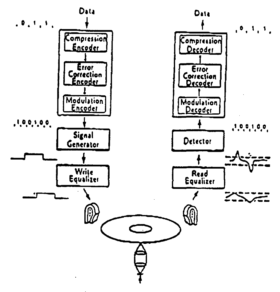
- FIG. 1 Traditional model for a magnetic recording system. This figure is from the Introduction to the Special Issue on Coding for Storage Devices, IEEE Transactions on Information Theory, vol. 37, Hay 1991, p. 709.
- Figure 2 Shown in Figures 2 is a block diagram description of the write-read-write recording process.
- Figure 2 shows three heads flying over a magnetic medium. The first records a diagnostic signal s 1 (t). The second reads the resulting magnetization on the medium. Third, a signal that has been computed by the electronics and includes the desired signal and compensation for the medium noise is written onto the medium. When the information is read at a later time, the signal-to-noise ratio will be significantly higher, resulting in better recovery of the desired signal.
- the crucial design of the electronics block is based on a model for the manner in which the medium noise is manifested. The discussion in this paper is based on an additive model for the medium noise.
- FIG 3 Shown in Figure 3 is an approximate linear model of a magnetic recording system.
- all blocks are assumed to be linear and time-invariant, all random processes are assumed to be wide-sense stationary.
- a diagnostic signal 5. (0 is written using the write head (h(t)), medium noise is added (n d (t) + n 1 (t)), the signal is read (g(t)) introducing electronics noise (w 1 (t)).
- h(t) medium noise
- the signal is read (g(t)) introducing electronics noise (w 1 (t)).
- the desired channel response is d(t).
- b(t) (g * h)(t) (where * denotes convolution).
- the error signal e(t) y 1 (t) - (b * s 1 )(t) equals the part of the received voltage waveform due to system noise.
- the noise has a repeatable component, n d (t), due to the medium, and two unrepeatable components, n 1 (t) due to the medium, and w 1 (t) due to the electronics.
- the goal is to compensate for the repeatable component To do this, e(t) is filtered, subtracted from s(t), the information-bearing signal to be recorded, then recorded with the write head again.
- the design problem may be stated as minimizing the distortion in the waveform y(t) that is eventually read due to the repeatable component of medium noise.
- c(t) may be designed from the reduced system shown in Figure 4. In that figure, the information-bearing signal s(t) and the diagnostic signal s 1 (t) have been removed. Let the distortion be measured in terms of noise power, Then the goal is to design c(t) to minimize the signal power in y c (t), the noise component of the output,
- C For any real system design, there will be a constraint class, for the c(t) so thai they are realizable.
- a typical constraint is that it be the output of a transversal filter with a fixed number of taps.
- the limiting increase in capacity is determined by the change in the power spectrum of the channel.
- the component due to the repeatable medium noise is attenuated. This attenuation increases as the energy of the repeatable component increases relative to the energy of the unrepeatable component.
- the capacity of the Gaussian channel is then increased; the increase depends on the spectral shapes (that is, system factors such as the g(t), h(t). and the noise levels) and detailed analysis of the standard water-filling capacity formula [9, p. 267].
- the repeatable component is one half to nine tenths the total noise power. If all of the repeatable medium noise is adequately modeled as additive noise, equation (7) implies a potential increase in signal to noise ratio of 1.2 to 7.2 dB.
- the constraint class is the set of c(t) such that
- ⁇ is a Dirac delta function
- T is the time interval between the taps.
- equation (10) may be rewritten compactly as
- the step response of the read head is given by
- TS/2 is the half width of the Lorentz pulse. Differentiating this with respect to t we get the impulse response function g(t) of the read head
- Figure 5 compares the noise powers before and after signal precompensation obtained in 1000 runs.
- Figures 6 and 7 show typical read waveforms obtained by writing the signal without and with compensation.
Abstract
Description


Claims
Priority Applications (3)
| Application Number | Priority Date | Filing Date | Title |
|---|---|---|---|
| EP94914041A EP0693202A1 (en) | 1993-04-09 | 1994-04-05 | Method and apparatus for noise reduction in magnetic media |
| JP6523277A JPH08508842A (en) | 1993-04-09 | 1994-04-05 | Method and apparatus for reducing noise on magnetic media |
| AU66263/94A AU680498B2 (en) | 1993-04-09 | 1994-04-05 | Method and apparatus for noise reduction in magnetic media |
Applications Claiming Priority (6)
| Application Number | Priority Date | Filing Date | Title |
|---|---|---|---|
| US08/046,071 | 1993-04-09 | ||
| US08/046,071 US5587654A (en) | 1993-04-09 | 1993-04-09 | Method and apparatus for noise reduction in magnetic media recordings |
| US08/046,040 | 1993-04-09 | ||
| US08/046,040 US5365586A (en) | 1993-04-09 | 1993-04-09 | Method and apparatus for fingerprinting magnetic media |
| US20899794A | 1994-03-10 | 1994-03-10 | |
| US08/208,997 | 1994-03-10 |
Publications (2)
| Publication Number | Publication Date |
|---|---|
| WO1994024639A1 true WO1994024639A1 (en) | 1994-10-27 |
| WO1994024639A9 WO1994024639A9 (en) | 1994-12-08 |
Family
ID=27366826
Family Applications (1)
| Application Number | Title | Priority Date | Filing Date |
|---|---|---|---|
| PCT/US1994/003722 WO1994024639A1 (en) | 1993-04-09 | 1994-04-05 | Method and apparatus for noise reduction in magnetic media |
Country Status (6)
| Country | Link |
|---|---|
| EP (1) | EP0693202A1 (en) |
| JP (1) | JPH08508842A (en) |
| AU (1) | AU680498B2 (en) |
| CA (1) | CA2159800A1 (en) |
| IL (1) | IL109208A0 (en) |
| WO (1) | WO1994024639A1 (en) |
Cited By (1)
| Publication number | Priority date | Publication date | Assignee | Title |
|---|---|---|---|---|
| US5959794A (en) * | 1993-04-09 | 1999-09-28 | Washington University | Method for precompensating signals for magnetic media noise |
Citations (2)
| Publication number | Priority date | Publication date | Assignee | Title |
|---|---|---|---|---|
| US4806740A (en) * | 1986-09-19 | 1989-02-21 | Light Signatures, Inc. | Magnetic characteristic identification system |
| US4837426A (en) * | 1987-01-16 | 1989-06-06 | Rand, Mcnally & Company | Object verification apparatus and method |
Family Cites Families (4)
| Publication number | Priority date | Publication date | Assignee | Title |
|---|---|---|---|---|
| JPS58196606A (en) * | 1982-05-11 | 1983-11-16 | Shigeaki Morita | Tape noise eliminating method of magnetic tape recorder |
| JPS59127209A (en) * | 1983-01-08 | 1984-07-23 | Oki Electric Ind Co Ltd | Removing method of external noise in read of magnetic medium |
| WO1994024669A1 (en) * | 1993-04-09 | 1994-10-27 | Washington University | Magnetic recording head with continuously monitored track following servo |
| US5408505A (en) * | 1993-04-09 | 1995-04-18 | Washington University | Method and apparatus for process control, tension control, and testing of magnetic media |
-
1994
- 1994-04-04 IL IL10920894A patent/IL109208A0/en unknown
- 1994-04-05 JP JP6523277A patent/JPH08508842A/en active Pending
- 1994-04-05 CA CA002159800A patent/CA2159800A1/en not_active Abandoned
- 1994-04-05 EP EP94914041A patent/EP0693202A1/en not_active Withdrawn
- 1994-04-05 AU AU66263/94A patent/AU680498B2/en not_active Ceased
- 1994-04-05 WO PCT/US1994/003722 patent/WO1994024639A1/en not_active Application Discontinuation
Patent Citations (2)
| Publication number | Priority date | Publication date | Assignee | Title |
|---|---|---|---|---|
| US4806740A (en) * | 1986-09-19 | 1989-02-21 | Light Signatures, Inc. | Magnetic characteristic identification system |
| US4837426A (en) * | 1987-01-16 | 1989-06-06 | Rand, Mcnally & Company | Object verification apparatus and method |
Cited By (1)
| Publication number | Priority date | Publication date | Assignee | Title |
|---|---|---|---|---|
| US5959794A (en) * | 1993-04-09 | 1999-09-28 | Washington University | Method for precompensating signals for magnetic media noise |
Also Published As
| Publication number | Publication date |
|---|---|
| EP0693202A1 (en) | 1996-01-24 |
| CA2159800A1 (en) | 1994-10-27 |
| AU6626394A (en) | 1994-11-08 |
| JPH08508842A (en) | 1996-09-17 |
| EP0693202A4 (en) | 1996-02-07 |
| AU680498B2 (en) | 1997-07-31 |
| IL109208A0 (en) | 1994-10-07 |
Similar Documents
| Publication | Publication Date | Title |
|---|---|---|
| US5587654A (en) | Method and apparatus for noise reduction in magnetic media recordings | |
| Palmer et al. | Identification of nonlinear write effects using pseudorandom sequences | |
| US5959794A (en) | Method for precompensating signals for magnetic media noise | |
| US5319502A (en) | System and method for employing buried servos within a magnetic recording medium | |
| Yamauchi et al. | A nonlinear model for thin film disk recording systems | |
| KR100462533B1 (en) | Record compensator for magnetic media proxy | |
| Ho et al. | Recording at 300 kfci with perpendicular Co-alloy multilayers | |
| AU680498B2 (en) | Method and apparatus for noise reduction in magnetic media | |
| Wei et al. | A simplified model of high density tape recording | |
| WO1994024639A9 (en) | Method and apparatus for noise reduction in magnetic media | |
| Sugita et al. | Magnetization patterns of slave media duplicated by using patterned master media | |
| Desserre | Crucial points in perpendicular recording | |
| Langland | Phase equalization for perpendicular recording | |
| WO1998018128A1 (en) | Method and apparatus for multiplicative noise precompensation for magnetic recordings | |
| US6288859B1 (en) | Device for write compensation in magnetic-media recording | |
| Che et al. | Dynamics of nonlinearities in high density recording | |
| Yamakoshi et al. | The effect of non-linear MR read-back distortion on a PRML channel | |
| US4521816A (en) | Magnetic recording method for digital signal | |
| Langland et al. | Processing of signals from media with perpendicular magnetic anisotropy | |
| Wong-Lam | Characterization and measurement of nonlinear bit shifts in digital magnetic tape recording | |
| US6212025B1 (en) | Magnetic recording and reproducing method and apparatus employing a magnetically continuous magnetic film | |
| Middleton | Models of the longitudinal digital magnetic recording process in thin films | |
| Kavcic et al. | Expedient media noise modeling: Isolated and interacting transitions | |
| Bertram et al. | Theory of nonlinearities and pulse asymmetry in high density tape recording | |
| Jeon et al. | Identification of nonlinear distortion in a digital high-density magnetic recording channel using an iid signal |
Legal Events
| Date | Code | Title | Description |
|---|---|---|---|
| AK | Designated states |
Kind code of ref document: A1 Designated state(s): AU BB BG BR BY CA CZ FI HU JP KP KR KZ LK MG MN MW NO NZ PL PT RO RU SD SK UA VN |
|
| AL | Designated countries for regional patents |
Kind code of ref document: A1 Designated state(s): AT BE CH DE DK ES FR GB GR IE IT LU MC NL PT SE BF BJ CF CG CI CM GA GN ML MR NE SN TD TG |
|
| COP | Corrected version of pamphlet |
Free format text: PAGE 2/3,DRAWINGS,REPLACED BY A NEW PAGE BEARING THE SAME NUMBER;AFTER RECTIFICATION OF OBVIOUS ERRORS AS AUTHORIZED BY THE INTERNATIONAL SEARCHING AUTHORITY |
|
| 121 | Ep: the epo has been informed by wipo that ep was designated in this application | ||
| DFPE | Request for preliminary examination filed prior to expiration of 19th month from priority date (pct application filed before 20040101) | ||
| WWE | Wipo information: entry into national phase |
Ref document number: 2159800 Country of ref document: CA |
|
| WWE | Wipo information: entry into national phase |
Ref document number: 1994914041 Country of ref document: EP |
|
| WWP | Wipo information: published in national office |
Ref document number: 1994914041 Country of ref document: EP |
|
| WWW | Wipo information: withdrawn in national office |
Ref document number: 1994914041 Country of ref document: EP |