WO1999010165A1 - Composite solid polymer electrolyte membranes - Google Patents
Composite solid polymer electrolyte membranes Download PDFInfo
- Publication number
- WO1999010165A1 WO1999010165A1 PCT/US1998/017898 US9817898W WO9910165A1 WO 1999010165 A1 WO1999010165 A1 WO 1999010165A1 US 9817898 W US9817898 W US 9817898W WO 9910165 A1 WO9910165 A1 WO 9910165A1
- Authority
- WO
- WIPO (PCT)
- Prior art keywords
- polymer
- spem
- ion
- substrate
- conducting
- Prior art date
Links
Classifications
-
- H—ELECTRICITY
- H01—ELECTRIC ELEMENTS
- H01M—PROCESSES OR MEANS, e.g. BATTERIES, FOR THE DIRECT CONVERSION OF CHEMICAL ENERGY INTO ELECTRICAL ENERGY
- H01M8/00—Fuel cells; Manufacture thereof
- H01M8/10—Fuel cells with solid electrolytes
- H01M8/1016—Fuel cells with solid electrolytes characterised by the electrolyte material
- H01M8/1018—Polymeric electrolyte materials
- H01M8/102—Polymeric electrolyte materials characterised by the chemical structure of the main chain of the ion-conducting polymer
- H01M8/1025—Polymeric electrolyte materials characterised by the chemical structure of the main chain of the ion-conducting polymer having only carbon and oxygen, e.g. polyethers, sulfonated polyetheretherketones [S-PEEK], sulfonated polysaccharides, sulfonated celluloses or sulfonated polyesters
-
- H—ELECTRICITY
- H01—ELECTRIC ELEMENTS
- H01M—PROCESSES OR MEANS, e.g. BATTERIES, FOR THE DIRECT CONVERSION OF CHEMICAL ENERGY INTO ELECTRICAL ENERGY
- H01M50/00—Constructional details or processes of manufacture of the non-active parts of electrochemical cells other than fuel cells, e.g. hybrid cells
- H01M50/40—Separators; Membranes; Diaphragms; Spacing elements inside cells
- H01M50/409—Separators, membranes or diaphragms characterised by the material
- H01M50/411—Organic material
- H01M50/414—Synthetic resins, e.g. thermoplastics or thermosetting resins
- H01M50/426—Fluorocarbon polymers
-
- H—ELECTRICITY
- H01—ELECTRIC ELEMENTS
- H01M—PROCESSES OR MEANS, e.g. BATTERIES, FOR THE DIRECT CONVERSION OF CHEMICAL ENERGY INTO ELECTRICAL ENERGY
- H01M50/00—Constructional details or processes of manufacture of the non-active parts of electrochemical cells other than fuel cells, e.g. hybrid cells
- H01M50/40—Separators; Membranes; Diaphragms; Spacing elements inside cells
- H01M50/409—Separators, membranes or diaphragms characterised by the material
- H01M50/411—Organic material
- H01M50/414—Synthetic resins, e.g. thermoplastics or thermosetting resins
- H01M50/423—Polyamide resins
-
- H—ELECTRICITY
- H01—ELECTRIC ELEMENTS
- H01M—PROCESSES OR MEANS, e.g. BATTERIES, FOR THE DIRECT CONVERSION OF CHEMICAL ENERGY INTO ELECTRICAL ENERGY
- H01M50/00—Constructional details or processes of manufacture of the non-active parts of electrochemical cells other than fuel cells, e.g. hybrid cells
- H01M50/40—Separators; Membranes; Diaphragms; Spacing elements inside cells
- H01M50/489—Separators, membranes, diaphragms or spacing elements inside the cells, characterised by their physical properties, e.g. swelling degree, hydrophilicity or shut down properties
- H01M50/491—Porosity
-
- H—ELECTRICITY
- H01—ELECTRIC ELEMENTS
- H01M—PROCESSES OR MEANS, e.g. BATTERIES, FOR THE DIRECT CONVERSION OF CHEMICAL ENERGY INTO ELECTRICAL ENERGY
- H01M50/00—Constructional details or processes of manufacture of the non-active parts of electrochemical cells other than fuel cells, e.g. hybrid cells
- H01M50/40—Separators; Membranes; Diaphragms; Spacing elements inside cells
- H01M50/489—Separators, membranes, diaphragms or spacing elements inside the cells, characterised by their physical properties, e.g. swelling degree, hydrophilicity or shut down properties
- H01M50/494—Tensile strength
-
- H—ELECTRICITY
- H01—ELECTRIC ELEMENTS
- H01M—PROCESSES OR MEANS, e.g. BATTERIES, FOR THE DIRECT CONVERSION OF CHEMICAL ENERGY INTO ELECTRICAL ENERGY
- H01M8/00—Fuel cells; Manufacture thereof
- H01M8/10—Fuel cells with solid electrolytes
- H01M8/1016—Fuel cells with solid electrolytes characterised by the electrolyte material
- H01M8/1018—Polymeric electrolyte materials
- H01M8/102—Polymeric electrolyte materials characterised by the chemical structure of the main chain of the ion-conducting polymer
- H01M8/1027—Polymeric electrolyte materials characterised by the chemical structure of the main chain of the ion-conducting polymer having carbon, oxygen and other atoms, e.g. sulfonated polyethersulfones [S-PES]
-
- H—ELECTRICITY
- H01—ELECTRIC ELEMENTS
- H01M—PROCESSES OR MEANS, e.g. BATTERIES, FOR THE DIRECT CONVERSION OF CHEMICAL ENERGY INTO ELECTRICAL ENERGY
- H01M8/00—Fuel cells; Manufacture thereof
- H01M8/10—Fuel cells with solid electrolytes
- H01M8/1016—Fuel cells with solid electrolytes characterised by the electrolyte material
- H01M8/1018—Polymeric electrolyte materials
- H01M8/102—Polymeric electrolyte materials characterised by the chemical structure of the main chain of the ion-conducting polymer
- H01M8/103—Polymeric electrolyte materials characterised by the chemical structure of the main chain of the ion-conducting polymer having nitrogen, e.g. sulfonated polybenzimidazoles [S-PBI], polybenzimidazoles with phosphoric acid, sulfonated polyamides [S-PA] or sulfonated polyphosphazenes [S-PPh]
-
- H—ELECTRICITY
- H01—ELECTRIC ELEMENTS
- H01M—PROCESSES OR MEANS, e.g. BATTERIES, FOR THE DIRECT CONVERSION OF CHEMICAL ENERGY INTO ELECTRICAL ENERGY
- H01M8/00—Fuel cells; Manufacture thereof
- H01M8/10—Fuel cells with solid electrolytes
- H01M8/1016—Fuel cells with solid electrolytes characterised by the electrolyte material
- H01M8/1018—Polymeric electrolyte materials
- H01M8/102—Polymeric electrolyte materials characterised by the chemical structure of the main chain of the ion-conducting polymer
- H01M8/1032—Polymeric electrolyte materials characterised by the chemical structure of the main chain of the ion-conducting polymer having sulfur, e.g. sulfonated-polyethersulfones [S-PES]
-
- H—ELECTRICITY
- H01—ELECTRIC ELEMENTS
- H01M—PROCESSES OR MEANS, e.g. BATTERIES, FOR THE DIRECT CONVERSION OF CHEMICAL ENERGY INTO ELECTRICAL ENERGY
- H01M8/00—Fuel cells; Manufacture thereof
- H01M8/10—Fuel cells with solid electrolytes
- H01M8/1016—Fuel cells with solid electrolytes characterised by the electrolyte material
- H01M8/1018—Polymeric electrolyte materials
- H01M8/1039—Polymeric electrolyte materials halogenated, e.g. sulfonated polyvinylidene fluorides
-
- H—ELECTRICITY
- H01—ELECTRIC ELEMENTS
- H01M—PROCESSES OR MEANS, e.g. BATTERIES, FOR THE DIRECT CONVERSION OF CHEMICAL ENERGY INTO ELECTRICAL ENERGY
- H01M8/00—Fuel cells; Manufacture thereof
- H01M8/10—Fuel cells with solid electrolytes
- H01M8/1016—Fuel cells with solid electrolytes characterised by the electrolyte material
- H01M8/1018—Polymeric electrolyte materials
- H01M8/1041—Polymer electrolyte composites, mixtures or blends
- H01M8/1044—Mixtures of polymers, of which at least one is ionically conductive
-
- H—ELECTRICITY
- H01—ELECTRIC ELEMENTS
- H01M—PROCESSES OR MEANS, e.g. BATTERIES, FOR THE DIRECT CONVERSION OF CHEMICAL ENERGY INTO ELECTRICAL ENERGY
- H01M8/00—Fuel cells; Manufacture thereof
- H01M8/10—Fuel cells with solid electrolytes
- H01M8/1016—Fuel cells with solid electrolytes characterised by the electrolyte material
- H01M8/1018—Polymeric electrolyte materials
- H01M8/1058—Polymeric electrolyte materials characterised by a porous support having no ion-conducting properties
- H01M8/106—Polymeric electrolyte materials characterised by a porous support having no ion-conducting properties characterised by the chemical composition of the porous support
-
- H—ELECTRICITY
- H01—ELECTRIC ELEMENTS
- H01M—PROCESSES OR MEANS, e.g. BATTERIES, FOR THE DIRECT CONVERSION OF CHEMICAL ENERGY INTO ELECTRICAL ENERGY
- H01M8/00—Fuel cells; Manufacture thereof
- H01M8/10—Fuel cells with solid electrolytes
- H01M8/1016—Fuel cells with solid electrolytes characterised by the electrolyte material
- H01M8/1018—Polymeric electrolyte materials
- H01M8/1058—Polymeric electrolyte materials characterised by a porous support having no ion-conducting properties
- H01M8/1062—Polymeric electrolyte materials characterised by a porous support having no ion-conducting properties characterised by the physical properties of the porous support, e.g. its porosity or thickness
-
- H—ELECTRICITY
- H01—ELECTRIC ELEMENTS
- H01M—PROCESSES OR MEANS, e.g. BATTERIES, FOR THE DIRECT CONVERSION OF CHEMICAL ENERGY INTO ELECTRICAL ENERGY
- H01M8/00—Fuel cells; Manufacture thereof
- H01M8/10—Fuel cells with solid electrolytes
- H01M8/1016—Fuel cells with solid electrolytes characterised by the electrolyte material
- H01M8/1018—Polymeric electrolyte materials
- H01M8/1067—Polymeric electrolyte materials characterised by their physical properties, e.g. porosity, ionic conductivity or thickness
-
- H—ELECTRICITY
- H01—ELECTRIC ELEMENTS
- H01M—PROCESSES OR MEANS, e.g. BATTERIES, FOR THE DIRECT CONVERSION OF CHEMICAL ENERGY INTO ELECTRICAL ENERGY
- H01M8/00—Fuel cells; Manufacture thereof
- H01M8/10—Fuel cells with solid electrolytes
- H01M8/1007—Fuel cells with solid electrolytes with both reactants being gaseous or vaporised
-
- H—ELECTRICITY
- H01—ELECTRIC ELEMENTS
- H01M—PROCESSES OR MEANS, e.g. BATTERIES, FOR THE DIRECT CONVERSION OF CHEMICAL ENERGY INTO ELECTRICAL ENERGY
- H01M8/00—Fuel cells; Manufacture thereof
- H01M8/10—Fuel cells with solid electrolytes
- H01M8/1009—Fuel cells with solid electrolytes with one of the reactants being liquid, solid or liquid-charged
-
- Y—GENERAL TAGGING OF NEW TECHNOLOGICAL DEVELOPMENTS; GENERAL TAGGING OF CROSS-SECTIONAL TECHNOLOGIES SPANNING OVER SEVERAL SECTIONS OF THE IPC; TECHNICAL SUBJECTS COVERED BY FORMER USPC CROSS-REFERENCE ART COLLECTIONS [XRACs] AND DIGESTS
- Y02—TECHNOLOGIES OR APPLICATIONS FOR MITIGATION OR ADAPTATION AGAINST CLIMATE CHANGE
- Y02E—REDUCTION OF GREENHOUSE GAS [GHG] EMISSIONS, RELATED TO ENERGY GENERATION, TRANSMISSION OR DISTRIBUTION
- Y02E60/00—Enabling technologies; Technologies with a potential or indirect contribution to GHG emissions mitigation
- Y02E60/10—Energy storage using batteries
-
- Y—GENERAL TAGGING OF NEW TECHNOLOGICAL DEVELOPMENTS; GENERAL TAGGING OF CROSS-SECTIONAL TECHNOLOGIES SPANNING OVER SEVERAL SECTIONS OF THE IPC; TECHNICAL SUBJECTS COVERED BY FORMER USPC CROSS-REFERENCE ART COLLECTIONS [XRACs] AND DIGESTS
- Y02—TECHNOLOGIES OR APPLICATIONS FOR MITIGATION OR ADAPTATION AGAINST CLIMATE CHANGE
- Y02E—REDUCTION OF GREENHOUSE GAS [GHG] EMISSIONS, RELATED TO ENERGY GENERATION, TRANSMISSION OR DISTRIBUTION
- Y02E60/00—Enabling technologies; Technologies with a potential or indirect contribution to GHG emissions mitigation
- Y02E60/30—Hydrogen technology
- Y02E60/50—Fuel cells
Definitions
- This invention relates to novel solid polymer electrolyte composite membranes (SPEMs) for use in electrochemical applications. Methods for producing the composite membranes of the invention are also disclosed.
- SPEMs solid polymer electrolyte composite membranes
- military applications include, but are not limited to, submersibles, surface ships, portable/mobile field generating units, and low power units (i.e., battery replacements).
- low range power sources a few watts to a few kilowatts
- Commercial applications include transportation (i.e., automotive, bus, truck and railway), communications, on-site cogeneration and stationary power generation.
- Fuel cells are highly efficient electrochemical energy conversion devices that directly convert the chemical energy derived from renewable fuel into electrical energy.
- Significant research and development activity has focussed on the development of proton-exchange membrane fuel cells.
- Proton-exchange membrane fuel cells have a polymer electrolyte membrane disposed between a positive electrode (cathode) and a negative electrode (anode).
- the polymer electrolyte membrane is composed of an ion-exchange polymer (i.e., ionomer). Its role is to provide a means for ionic transport and prevent mixing of the molecular forms of the fuel and the oxidant.
- Solid polymer electrolyte fuel cells are an ideal source of quiet, efficient, and lightweight power. While batteries have reactants contained within their structure which eventually are used up, fuel cells use air and hydrogen. Their fuel efficiency is high (45 to 50 percent), they do not produce noise, operate over a wide power range (10 watts to several hundred kilowatts), and are relatively simple to design, manufacture and operate. Further, SPEFCs currently have the highest power density of all fuel cell types. In addition, SPEFCs do not produce any environmentally hazardous emissions such as NOx and SOx (combustion by-products).
- the traditional SPEFC contains a solid polymer ion-exchange membrane that lies between two gas diffusion electrodes, an anode and a cathode, each commonly containing a metal catalyst supported by an electrically conductive material.
- the gas diffusion electrodes are exposed to the respective reactant gases, the reductant gas and the oxidant gas.
- An electrochemical reaction occurs at each of the two junctions (three phase boundaries) where one of the electrodes, electrolyte polymer membrane and reactant gas interface.
- Ion exchange membranes play a vital role in SPEFCs.
- the ion-exchange membrane has two functions: (1) it acts as the electrolyte that provides ionic communication between the anode and cathode; and (2) it serves as a separator for the two reactant gases (e.g., 0 2 and H 2 ).
- the ion-exchange membrane while serving as a good proton transfer membrane, also must have low permeability for the reactant gases to avoid cross-over phenomena that reduce performance of the fuel cell. This is especially important in fuel cell applications in which the reactant gases are under pressure and the fuel cell is operated at elevated temperatures.
- Fuel cell reactants are classified as oxidants and reductants on the basis of their electron acceptor or electron donor characteristics.
- Oxidants include pure oxygen, oxygen-containing gases (e.g., air) and halogens (e.g., chlorine).
- Reductants include hydrogen, carbon monoxide, natural gas, methane, ethane, formaldehyde and methanol.
- SPEFCs have not yet been commercialized due to unresolved technical problems and high overall cost.
- One major deficiency impacting the commercialization of the SPEFC is the inherent limitations of today's leading membrane and electrode assemblies.
- the membranes employed must operate at elevated/high temperatures (>120°C) so as to provide increased power density, limit catalyst sensitivity to fuel impurities. This would also allow for applications such as on-site cogeneration (high quality waste heat).
- Current membranes also allow excessive methanol crossover in liquid feed direct methanol fuel cells (approximately 50 to 200 mA/cm 2 @ 0.5V). This crossover results in poor fuel efficiency as well as limited performance levels.
- Nafion® membrane technology is well known in the art and is described e.g. in U.S. Patent Nos. 3,282,875 and 4,330,654.
- Unreinforced Nafion® membranes are used almost exclusively as the ion exchange membrane in present SPEFCs applications.
- This membrane is fabricated from tetrafluoroethylene (TFE), also known as Teflon®, and a vinyl ether comonomer.
- TFE tetrafluoroethylene
- Teflon® tetrafluoroethylene
- vinyl ether comonomer is copolymerized with TFE to form a melt-fabricable polymer. Once in the desired shape, the sulfonyl fluoride group is hydrolyzed into the ionic sulfonate form.
- the fluorocarbon component and the ionic groups are incompatible (the former is hydrophobic, the latter is hydrophilic) . This causes a phase separation, which leads to the formation of interconnected hydrated ionic "clusters".
- the properties of these clusters determine the electrochemical characteristics of the polymer, since protons are conducted through the membrane as they "hop" from one ionic cluster to another.
- each acid group needs a minimum amount of water to surround it and form a cluster. If the acid group concentration is too low (or hydration is insufficient) proton transfer will not occur. At higher acid group concentrations (or increased hydration levels) proton conductivity is improved, but membrane mechanical characteristics are sacrificed. As the membrane temperature is increased, the swelling forces
- the Nafion® membrane/ electrode is also very expensive to produce, and as a result it is not (yet) commercially viable.
- membrane cost is crucial to the commercialization of SPEFCs. It is estimated that membrane cost must be reduced by at least an order of magnitude from the Nafion® model for SPEFCs to become commercially attractive.
- Gore-Select® Another type of ion-conducting membrane, Gore-Select® (commercially available from W.L. Gore), is currently being developed for fuel cell applications. Gore- Select® membranes are further detailed in a series of U.S. Patents (U.S. 5,635,041 , 5,547,551 and 5,599,614).
- Gore discloses a composite membrane consisting of a Teflon® fluoropolymer film filled with a Nafion® ion-conducting solution. Although it has been reported to show high ionic conductivity and greater dimensional stability than Nafion® membranes, the Teflon and Nafion® materials selected and employed by Gore as the film substrate and the ion- exchange material, respectively, may not be appropriate for operation in SPEFCs. Teflon® undergoes extensive creep at temperatures above 80°C, and Nafion® swells and softens above the same temperature. This can result in the widening of interconnected channels in the membrane and allow performance degradation, especially at elevated temperatures and pressures.
- Gore-Select® as well as many other types of perfluorinated ion-conducting membranes, are just as costly as Nafion®, since these membranes also use a high percentage of Nafion® and Nafion®-like ionomers.
- ion-exchange membranes that were less expensive to produce also have been investigated for use in polymer electrolyte membrane fuel cells.
- Poly(txifluorostyrene) copolymers have been studied as membranes for use in polymer electrolyte membrane fuel cells. See e.g., U.S. Patent No. 5,422,411.
- Sulfonated poly(aryl ether ketones) developed by Hoechst AG are described in European Patent No. 574, 891, A2. These polymers can be cross-linked by primary and secondary amines. However, when used as membranes and tested in polymer electrolyte membrane fuel cells, only modest cell performance is observed. Sulfonated polyaromatic based systems, such as those described in U.S. Patent Nos. 3,528,858 and 3,226,361 , also have been investigated as membrane materials for SPEFCs. However, these materials suffer from poor chemical resistance and mechanical properties that limit their use in SPEFC applications.
- Solid polymer membranes comprising a sulfonated poly(phenylene oxide) alone or blended with poly(vinylidene fluoride) also have been investigated. These membranes are disclosed in WO 97/24777. However, these membranes are known to be especially vulnerable to degradation from peroxide radicals.
- the present invention provides innovative solid polymer electrolyte membranes that are capable of operating at much higher temperatures and pressures than those known in the art. Methods for producing such membranes are also provided. The membrane manufacturing technologies developed emphasize improved performance at reduced cost.
- a central object of the invention is to provide an improved solid polymer electrolyte membrane (SPEM) having the following characteristics: high ionic conductivity, high resistance to dehydration, high mechanical strength, chemical stability during oxidation and hydrolysis, low gas permeability to limit parasitic losses, and stability at elevated temperatures and pressures.
- SPEM solid polymer electrolyte membrane
- Another object of the invention is to provide an improved solid polymer electrolyte membrane with electronic conductivity approaching zero, dimensional stability, and a membrane that is non-brittle in both dry and wet forms.
- Another object of the invention is to provide an improved solid polymer electrolyte membrane that is resistant to methanol cross-over when used in a direct methanol fuel cell.
- Yet another object of the invention is to lower the overall cost of producing solid polymer electrolyte membranes to allow for commercialization of SPEFCs.
- a further object of the invention is to provide methods that can be employed to produce these solid polymer electrolyte membranes.
- Another object of this invention is to provide novel substrate polymers and ion-conducting materials and novel combinations thereof.
- Yet another object of the present invention is to provide SPEMs that are substantially stable to temperatures of at least about 100°C, preferably to at least about 150°C, more preferably to at least about 175°C.
- a high performance SPEM suitable for use in fuel cells, can be produced by interpenetrating a porous polymer substrate with an ion-conducting material to form a composite membrane.
- This composite ion-conducting membrane will exhibit the strength and thermal stability of the substrate polymer and the excellent ionic conductivity of the ion-conducting material.
- the composite SPEM of the present invention comprises a porous substrate polymer substrate that is interpenetrated with an ion-conducting material.
- the present invention also provides novel substrates and novel substrate /ion-conducting material combinations. These materials can be tailored and combined to produce membranes useful over a range of operating conditions and /or applications.
- Preferred substrate polymers are easily synthesized from commercially- available, low-cost starting polymers, into thin, substantially defect free polymeric films which have high strength even at low thickness (in preferred embodiments less than about 1 mil), outstanding crease /crack resistance and high tear strength.
- Preferred substrate polymers are substantially chemically resistant to acids, bases, free radicals and solvents (i.e., methanol) and are thermally and hydrolytically stable from temperatures of about 50°C to 300°C.
- Preferred substrate polymers possess exceptional mechanical properties (much greater than about 2,500 psi tensile, much less than about 100% elongation to break), dimensional stability, barrier properties (to methanol, water vapor, oxygen and hydrogen) even at elevated temperatures and pressures and exceptional gauge uniformity (+/- 0.2 mils preferable).
- the substrate polymers are thermally and hydrolytically stable to temperatures of at least about 100°C.
- Preferred polymer substrates have a pore size range of lOA to 2000 A more preferably 50 ⁇ A to 1000 A, and have a porosity range from about 40% to 90%.
- the substrate polymer of the SPEM comprises a lyotropic liquid crystalline polymer, such as a polybenzazole (PBZ) or polyaramid (PAR or Kevlar®) polymer.
- Preferred polybenzazole polymers include polybenzoxazole (PBO), polybenzothiazole (PBT) and polybenzimidazole (PBI) polymers.
- Preferred polyaramid polymers include polypara-phenylene terephthalimide (PPTA) polymers.
- the substrate polymer of the SPEM comprises a thermoplastic or thermoset aromatic polymer.
- Preferred aromatic polymers include: polysulfone (PSU), polyimide (PI), polyphenvlene oxide (PPO), polyphenvlene sulfoxide (PPSO), polyphenylene sulfide (PPS), polyphenylene sulfide sulfone (PPS/SO2), polyparaphenylene (PPP), polyphenylquinoxaline (PPQ) , polyarylketone (PK) and polyetherketone (PEK) polymers.
- PSU polysulfone
- PI polyimide
- PPO polyphenvlene oxide
- PPSO polyphenvlene sulfoxide
- PPS polyphenylene sulfide
- PPS/SO2 polyphenylene sulfide sulfone
- PPP polyparaphenylene
- PPQ polyphenylquinoxaline
- PK polyarylketone
- PEK polyetherket
- Preferred polysulfone polymers include polyethersulfone (PES), polyetherethersulfone (PEES), polyarylsulfone, polyarylethersulfone (PAS), polyphenylsulfone (PPSU) and polyphenylenesulfone (PPSO2) polymers.
- Preferred polyimide polymers include the polyetherimide polymers as well as fluorinated (5 membered ring) polyimides.
- Preferred polyetherketone polymers include polyetheretherketone (PEEK), polyetherketone-ketone (PEKK), polyetheretherketone-ketone (PEEKK) and polyetherketoneetherketone-ketone (PEKEKK) polymers.
- Preferred ion-conducting polymers for use in the fuel cells of the present invention are easily sulfonated or synthesized from commercially- available, low-cost starting polymers, and are swellable, but highly insoluble in boiling water ( 100°C) or aqueous methanol (>50%) over extended time periods.
- Preferred ion-conducting polymers have limited methanol permeability (limited methanol diffusivity and solubility) even at elevated temperatures and pressures, are substantially chemically stable to acids and free radicals, and thermally/ hydrolytically stable to temperatures of at least about 100°C.
- Preferred ion-conducting polymers have an ion-exchange capacity (IEC) of > 1.0meq/g dry membrane (preferably, 1.5 to 2.0meq/g) and are highly ion-conducting (preferably, from about 0.01 to about 0.5S/cm, more preferably, to greater than about 0.1 S/cm or ⁇ lO ⁇ cm resistivity).
- Preferred ion-conducting polymers are easily cast into films and/ or imbibed into the polymer substrate. Such films are durable, substantially defect-free, and dimensionally stable (less than about 20% change in dimension wet to dry), preferably even above temperatures of at least about 100°C. Particularly preferred ion-conducting polymers have the ability to survive operation in fuel cells (i.e., H2/O2, methanol) for at least about 5000 hours (automotive).
- fuel cells i.e., H2/O2, methanol
- the ion- conducting material of the SPEM comprises a sulfonated, phosphonated or carboxylated ion-conducting aromatic polymer or a perfluorinated ionomer.
- it may comprise a sulfonated derivative of at least one of the above-listed thermoset or thermoplastic aromatic polymers. It may also comprise a sulfonated derivative of a polybenzazole or polyaramid polymer.
- the ion-conducting material of the SPEM of the present invention comprises a non-aromatic polymer, such as a perfluorinated ionomer.
- Preferred iono ers include carboxyl-, phosphonyl- or sulfonyl- substituted perfluorinated vinyl ethers.
- PSSA polystyrene sulfonic acid
- PVA polyvinyl phosphonic acid
- PVCA polyvinyl carboxylic acid
- PVSA polyvinyl sulfonic acid
- Substrate and ion-conducting polymers for use in the present invention may be substituted or unsubstituted and may be homopolymers or copolymers of the polymers listed above. Representative formulae of the unsubstituted monomers can be found in the Tables at the end of the Detailed Description of the Invention.
- one preferred method of fabricating a membrane of the present invention comprises the following steps: solubilizing the ion-conducting material, preparing a substrate polymer membrane, swelling the membrane with water, solvent exchanging the water swollen membrane, imbibing the solvent swollen substrate with the ion-conducting material via solution infiltration such that the microinfrastructure of the porous substrate polymer is substantially interpenetrated with the ion-conducting material.
- Post imbibing steps may include tension drying, stretching and hot pressing the composite membrane.
- the substrate will provide mechanical and chemical stability, while the ion-conductor provides a high-flux proton path.
- the SPEMs also act as a barrier against fuel (H 2 , 0 2 and methanol permeation) in fuel cell applications.
- Another preferred method of producing the membranes of the present invention comprises the steps of preparing a mixture of the porous substrate polymer and the ion-conducting material in a common solvent and casting a composite membrane from the mixture.
- Preferred solvents for these methods include tetrahydrofuran (THF) , dimethylacetamide (DMAc), dimethylformamide (DMF), dimethylsulfoxide (DMSO), N-Methyl-Z-pyrrolidinone (NMP), sulfuric acid, phosphoric acid, chlorosulfonic acid polyphosphoric acid (PPA) and methanesulfonic acid (MSA).
- THF tetrahydrofuran
- DMAc dimethylacetamide
- DMF dimethylformamide
- DMSO dimethylsulfoxide
- NMP N-Methyl-Z-pyrrolidinone
- sulfuric acid sulfuric acid
- phosphoric acid chlorosulfonic acid polyphosphoric acid
- MSA methanesulfonic acid
- MSA methanesulfonic acid
- Yet another method of producing a membrane of the present invention comprises the steps of preparing a mixture of a porous substrate polymer and an ion-conducting material and extruding a composite film directly from the mixture.
- Still another method of producing a membrane of the present invention comprises the steps of sulfonating the pores of the substrate polymer with a sulfonating agent.
- the membranes of the present invention are useful in a variety of electrochemical devices, including fuel cells, electronic devices, systems for membrane-based water electrolysis, chloralkali electrolysis, dialysis or electrodialysis, pervaporation or gas separation.
- Fig. 1 is a schematic illustrating the preparation of one composite membrane of the present invention.
- Fig. 2 shows a graph of % dry loading of ICP/PBO vs. initial ICP solution wt% for Nafion®/PBO, Radel R®/PBO and Sulfide-Sulfone/PBO in accordance with the present invention.
- the composite membrane of the present invention is designed to address the present shortcomings of today's solid polymer electrolyte membranes, specifically, Nafion® and other like membranes (e.g., Gore- Select®).
- the present invention provides a relatively low cost, composite solid polymer electrolyte membrane (SPEM), with improved power density and reduced sensitivity to carbon monoxide in hydrogen fuel. It also alleviates water management problems which limit the efficiency of present Nafion® membrane-based fuel cells.
- SPEM composite solid polymer electrolyte membrane
- the composite membrane of the present invention may be employed in various applications, including but not limited to, polarity-based chemical separations; electrolysis; fuel cells and batteries; pervaporation; reverse osmosis - water purification, gas separation; dialysis separation; industrial electrochemistry, such as choralkali production and other electrochemical applications; water splitting and subsequent recovery of acids and bases from waste water solutions; use as a super acid catalyst; or use as a medium in enzyme immobilization, for example; or use as an electrode separator in conventional batteries.
- the composite SPEM of the present invention comprises a porous polymer substrate interpenetrated with an ion-conducting polymer.
- the porous polymer substrate serves as a mechanically, thermally, chemically and oxidatively durable support for the ion-conducting material, e.g., polymer.
- Ion conducting polymers ICPs with very high ion-exchange capacities (IEC>2.0 meq/g) can be used in the SPEMs of the present invention, since the strength properties of the ICP are not needed for membrane mechanical integrity.
- ICPs Ion conducting polymers
- IEC very high ion-exchange capacities
- the porous polymer substrate is characterized by a microinfrastructure of channels that have substantially uniform, unchanging dimensions (T g is higher than use temperature). That is, the substrate material will not flow, since the operating temperature is less than the Tg of the substrate.
- the ion-conducting polymer substantially interpenetrates the microinfrastructure of the porous polymer substrate. This configuration, which can be made quite thin, promotes efficient proton transport across the membrane and minimizes water management problems. As a consequence, eventual membrane dehydration, parasitic losses and loss of ionic conductivity can be substantially prevented.
- thermally stable, wholly aromatic polymers are used in producing the composite membranes of the present invention, but any material(s) meeting the following requirements may generally be used: low cost, high ionic conductivity, electronically insulating, impermeable to fuel (H 2 , 0 2 , methanol) permeation at elevated temperatures and pressures in fuel cell applications, chemically resistant to acids, bases and free radicals, Tg above fuel cell operating temperature (at least about 175°C is preferred), minimal water transport rate during operation, resistance to puncture or burst during operation at high temperatures and pressures, and maintenance of ionic conductivity at elevated/high operating temperatures.
- Tg above fuel cell operating temperature at least about 175°C is preferred
- Tg above fuel cell operating temperature (at least about 175°C is preferred)
- minimal water transport rate during operation resistance to puncture or burst during operation at high temperatures and pressures
- maintenance of ionic conductivity at elevated/high operating temperatures The selection criteria for substrate polymers and ion-conducting polymer suitable for SPEMs
- Preferred substrate polymers are easily synthesized from commercially- available, low-cost starting polymers, into thin, substantially defect free polymeric films which have high strength even at low thickness (preferably less than about 1 mil), outstanding crease/crack resistance and high tear strength.
- Preferred substrate polymers are substantially chemically resistant to acids, bases, free radicals and solvents (i.e., methanol) and are thermally and hydrolytically stable from temperatures of about 50°C to 300°C.
- Preferred substrate polymers possess exceptional mechanical properties (much greater than about 2,500 psi tensile, much less than about 100% elongation to break), dimensional stability, barrier properties (to methanol, water vapor, oxygen and hydrogen) even at elevated temperatures and pressures and exceptional gauge uniformity (+/- 0.2 mils a preferable).
- the substrate polymers are thermally and hydrolytically stable to temperatures of at least about 100°C.
- Preferred polymer substrates have a pore size range of lOA to 2000 A more preferably 50 ⁇ A to lOOOA, and have a porosity range from about 40% to 90%.
- the porous polymer substrate of the SPEM comprises a lyotropic liquid crystalline polymer, such as a polybenzazole (PBZ) or polyaramid (PAR or Kevlar®) polymer.
- Preferred polybenzazole polymers include polybenzoxazole (PBO) , polybenzothiazole (PBT) and polybenzimidazole (PBI) polymers.
- Preferred polyaramid polymers include polypara-phenylene terephthalamide (PPTA) polymers. Structures of the above-mentioned polymers are listed in Table 4.
- the porous polymer substrate of the SPEM comprises a thermoplastic or thermoset aromatic polymer.
- Preferred groups of these aromatic polymers include the following: polysulfone (PSU), polyimide (PI), polyphenylene oxide (PPO), polyphenylene sulfoxide (PPSO), polyphenylene sulfide (PPS), polyphenylene sulfide sulfone (PPS/SO2), polyparaphenylene (PPP), polyphenylquinoxaline (PPQ), polyarylketone (PK) and polyetherketone (PEK) polymers.
- PSU polysulfone
- PI polyimide
- PPO polyphenylene oxide
- PPSO polyphenylene sulfoxide
- PPS polyphenylene sulfide
- PPS/SO2 polyphenylene sulfone
- PPP polyparaphenylene
- PPQ polyphenylquinoxaline
- PK polyarylketone
- PEK polyetherketone
- Preferred polysulfone polymers include polyethersulfone (PES), polyetherethersulfone (PEES), polyarylsulfone polyarylethersulfone (PAS), polyphenylsulfone (PPSU) and polyphenylenesulfone (PPSO2) polymers.
- Preferred polyimide polymers include the polyetherimide polymers and fluorinated polyimides.
- Preferred polyetherketone polymers include polyetheretherketone (PEEK), polyetherketone-ketone (PEKK), polyetheretherketone-ketone (PEEKK) and polyetherketoneetherketone- ketone (PEKEKK) polymers. The structures of the above polymers are listed in Tables 5 and 6.
- the porous substrate polymer comprises a PBO or a PES polymer.
- the porous substrate polymer comprises a PBO polymer, such as a poly(benzo-bisoxazole).
- the PBO polymer is a member of a relatively new class of polymeric materials collectively referred to as ordered polymers.
- ordered polymers As a result of its rigid-rod-like molecular structure, PBO forms liquid crystalline solutions from which extremely strong stiff fibers and films have been processed.
- Foster-Miller has pioneered the development of innovative methods for processing PBO into microporous high-strength high-modulus thermally- stable films that are useful for a multitude of high-performance applications, e.g., in advanced aircraft and spacecraft.
- the PBO polymer When the PBO polymer is in a dry (entirely collapsed) form it has the following characteristics: high strength and dimensional stability, superior barrier (gaseous) properties, excellent crease/crack resistance, excellent tear strength, and superior thermal and hydrolytic temperature stability (>300°C).
- Film-forming processes involve several operations in which a PBO polymer solution in polyphosphoric acid undergoes a succession of structural changes, leading to the final product form.
- One basic process for producing PBO products includes extrusion of the substrate polymer solution (polymer and acid solvent) , coagulation to lock-in the molecular structure, washing to remove the acid solvent, and drying (at high temperatures) to remove the exchanged water and consolidate the polymer into the end product.
- the PBO film is extruded and multiaxially oriented using a blown process as disclosed, e.g., in U.S. Patent Nos. 4,939,235, 4,963,428 and 5,288,529 which are incorporated herein by reference.
- the degree of multiaxial orientation can be varied from ⁇ ⁇ of 5° to 65°, though an orientation of 22° to 30° is preferred.
- imbibtion of an insufficient amount of ion-conducting polymer inside the porous substrate and/ or inability to maintain, if desired, a smooth outer layer of ion-conducting polymer for proper bonding are encountered, they may be overcome by heating the of ion-conducting polymer solution during imbibtion into the substrate (decreases the solution viscosity and swells the pores of the substrate) and using less oriented films (allows more ion-conducting polymer into the substrate, decreased bubble point).
- the substrate polymer processing system includes a hydrolic flask, extruder, pump, counter-rotating die (CRD), porous ring, water wash tank/ collapse shed and film take-up system.
- the take- up system includes a 3" porous sizing ring followed by a 6" diameter take-up roll along with a 4" diameter spooler. A number of CRDs and annular configurations may be used.
- AT Information was collected and recorded for wet film thickness, dry film thickness, draw ratio, blow-up ratio, overall film quality (veins, thin spots, voids, cracks, etc.) and extrusion system settings.
- Samples (wet and dry) of PBO film from each extrusion run were tested for tensile strength and tensile modulus, bubble point, pore size distribution, total pore volume and mean pore size, gas vapor (H 2 0, 0 2 ) permeability, zinc metal level in polymer.
- a liquid to solid phase transition is induced by diffusion of a non-solvent (water) into the PBO solution.
- a non-solvent water
- the final structure of the solid is established. It is believed that the structure formed during the coagulation stage of PBO fiber and film was an interconnected network of highly oriented microfibrils of 80 to 100 A diameter. Such films have been dried under tension in order to produce high tensile properties.
- the micropores present as spaces between microfibrils in PBO film undergo substantial shrinkage decreasing in dimensions from several thousand Angstroms (e.g. , 2000 A) in size to less than 10 A in size for the dried heat-treated PBO film. The final pore size depends highly upon the heat treatment methods employed.
- the present invention instead of drying the water from the network, the water is replaced by the desired ion-conducting material.
- a high performance PBO fuel cell membrane can be produced by interpenetrating the interior porosity of water-swollen PBO films with concentrated or dilute solutions of ion conducting polymers, such as Nafion® or polyethersulfone polysulfonic acid.
- ion conducting polymers such as Nafion® or polyethersulfone polysulfonic acid.
- Nafion® membrane supported by the porous PBO membrane substrate Nafion® membrane supported by the porous PBO membrane substrate.
- the substrate will accommodate about 40 to about 90, preferably about 70 to about 80 volume percent of ion-conducting polymer.
- PES is a high use temperature amorphous thermoplastic that exhibits long-term stability at elevated temperature (> 175°C).
- the microporous PES substrate represents a new class of high performance fuel cell membranes that can be used to solve the difficulties inherent in current Nafion® membranes as discussed above. PES is readily available from Amoco Performance, Inc. in Alpharetta,
- Microporous PES films for use in the SPEMs of the present invention can be produced via standard film casting techniques or purchased directly from appropriate vendors.
- PES is dissolved in an appropriate water-miscible solvent to a predetermined concentration.
- a wt% solution of PES is selected to produce a film with minimized (preferably less than about 1 mil) thickness.
- the PES solution is then cast onto glass plates to form, e.g., an about 0.5 mil thick film.
- the membrane can be dried first and then infiltrated with the ion-conducting solution using vacuum to remove air bubbles and fill the pores with Nafion®.
- the membrane may also be produced by an extrusion process as described herein.
- Preferred ion-conducting polymers for use in the present invention are easily sulfonated or synthesized from commercially- available, low-cost starting polymers, and are swellable, but highly insoluble in boiling water (100°C) or aqueous methanol (>50%) over extended time periods.
- Preferred ion- conducting polymers have limited methanol permeability (limited methanol diffusivity and solubility) even at elevated temperatures and pressures, are substantially chemically stable to acids and free radicals, and thermally/ hydrolytically stable to temperatures of at least about 100°C.
- Preferred ion-conducting polymers have an ion-exchange capacity (IEC) of > 1.0meq/g dry membrane (preferably, 1.5 to 2.0meq/g) and are highly ion- conducting (preferably, from about 0.01 to about 0.5S/cm, more preferably, to greater than about 0.1 S/cm or ⁇ lO ⁇ cm resistivity).
- IEC ion-exchange capacity
- Preferred ion- conducting polymers are easily cast into films and/ or imbibed into the polymer substrate. Such films are durable, substantially defect-free, and dimensionally stable (less than about 20% change in dimension wet to dry) even above temperatures of at least about 100 ° C.
- Preferred ion-conducting polymers have the ability to survive operation in fuel cells (i.e., H2/O2, methanol) for at least about 5000 hours (automotive).
- Preferred ion-conducting polymers are substantially chemically stable to free radicals.
- Cross-linking methods or the use of additives can also provide or enhance peroxide stability.
- the peroxide (H2O2) screening test serves as an accelerated fuel cell life test.
- the test simulates long term fuel cell operation by exposing the subject aqueous ion-conducting membrane to a peroxide/iron solution at 68°C for 8.0 hours. Under these conditions, aggressive hydroperoxide
- the ion conducting component polymer can be cross-linked via heating to slow membrane degradation.
- the ion- conducting material of the SPEM comprises a sulfonated (SO3H), phosphonated (PO(OH)2> or carboxylated (COOH) aromatic polymer.
- SO3H sulfonated
- PO(OH)2> phosphonated
- COOH carboxylated
- carboxylated solid polymer electrolytes see Solid State Ionics, 40:41 (1990), 624-627.
- it may comprise a sulfonated derivative of at least one of the above-listed thermoset or thermoplastic aromatic polymers. It may also comprise a sulfonated derivative of a polybenzazole or polyaramid polymer.
- the ion-conducting material of the SPEM of the present invention comprises a non-aromatic polymer, such as a perfluorinated ionomer.
- a non-aromatic polymer such as a perfluorinated ionomer.
- Preferred ionomers include carboxyl-, phosphonyl- or sulfonyl-substituted perfluorinated vinyl ethers.
- ion-conducting materials for use in the present invention include polystyrene sulfonic acid (PSSA), polytrifluorostyrene sulfonic acid, polyvinyl phosphonic acid (PVPA), polyvinyl carboxylic acid (PVCA) and polyvinyl sulfonic acid (PVSA) polymers, and metal salts thereof. More preferably, the ion-conducting material comprises a sufonated derivative of a polyphenylsulfone (PPSU), polyethersulfone (PES), polyimide (PI), polyphenylene sulfoxide (PPSO) and polyphenylenesulfide-sulfone (PPS/SO2). These polymers and additional preferred polymers are listed in Table 7.
- surfactants or surface active agents having a hydrophobic portion and hydrophilic portion may be utilized in promoting the interpenetration of the ion-conducting polymer into the pores of the substrate polymer.
- surfactants or surface active agents having a hydrophobic portion and hydrophilic portion may be utilized in promoting the interpenetration of the ion-conducting polymer into the pores of the substrate polymer.
- These agents are well known in the art and include Triton X- 100 (commercially available from Rohm & Haas of Philadelphia, PA).
- Compatibilizers may also be employed in producing composite membranes of the present invention.
- "compatibilizers” refer to agents that aid in the blendability of two or more polymers that would otherwise be resistant to such blending. Examples include block copolymers containing connecting segments of each component. These include potential substrate and/ or ion-conducting polymer components.
- the SPEMs and methods of the present invention will be illustrated by specific combinations of substrate polymers and ion-conducting polymers. However, the present invention should not be construed as being limited in use to any particular substrate polymer or ion-conducting material. Rather, the present teachings are suitable for any substrate polymer and ion-conducting material meeting the criteria set forth herein.
- the first method uses Nafion® as an example of a suitable ion- exchange material, in order to demonstrate the clear advantage of using the composite SPEM of the present invention.
- a porous membrane have the desired pore size and pore content is made using a suitable substrate polymer, e.g., PES or PBO. Either casting or extrusion processes are utilized to produce these membranes as described above.
- the pores of the porous substrate polymer membrane are then interpenetrated with an ICP, e.g., solubilized Nafion® ion-conducting polymer.
- the Naf ⁇ on®-interpenetrated porous membrane is then immersed into a dilute acid releasing the insoluble free sulfonic acid form of Nafion® as a high ionically conducting gel within the micropores and as thin coatings on the surfaces of the membrane.
- the flexible, pressure- resistant, high Tg, porous substrate provides puncture and crush-resistance to the thin coating of ion conductor membrane and also to the Nafion®-filled micropores even at temperatures above 175°C (the Tg of PES is 220°C, PBO has no Tg) .
- Composite membrane porosity is controlled during the imbibtion processes by varying the %wt of ion conducting material in solution to produce a membrane with numerous pores (preferably microscopic) of substantially uniform dimensions (preferably ⁇ about lOOOA).
- the substrate polymer is dissolved in an appropriate water-miscible solvent to a predetermined concentration.
- the wt% solution of substrate polymer is selected to produce a film with rninimized (preferably ⁇ lmil) thickness.
- the substrate polymer solution is then cast onto glass plates to form -0.5 mil thick film. Immersion of the plates in water coagulates the polymer and leaches out the solvent forming the microporous substrate membrane in a water swollen state.
- Nafion® or other ion-conducting polymers
- the membrane can be dried first and then infiltrated with Nafion® solution using vacuum to remove air bubbles and fill the pores with Nafion®.
- the membrane may also be produced by an extrusion process as described herein.
- porous substrate polymer membranes containing an ion-conducting material can also be produced by casting the membranes from a common solution containing appropriate concentrations of the substrate polymer and ion-conducting material. Determination of %wt ion conductor/ %wt. substrate are based on the desired final thickness, % volume of ion conducting polymer and the particular polymers employed. In some instances, this process may produce composite membranes in which the ion-conducting polymer domain sizes are smaller and more uniform than in composite membranes produced by imbibing pre-formed porous substrate membranes. In this process, pore size and content can be more easily controlled in the membrane by adjustment of individual component concentrations. The % wt.
- the ion-conducting polymer solution can be prepared by dissolving the ion- conducting polymer in sulfonate salt form in hot alcohol /water mixtures (e.g., Nafion 1 100 EW solution, 5% from Dupont).
- Preferred cosolvents include but are not limited to the following: tetrahydrofuran (THF), dimethylacetamide (DMAc), dimethylformamide
- a substrate polymer is chemically sulfonated to produce a sulfonated composite in situ. This concept draws on a number of technologies. A variety of methods exist for the fabrication of porous polymer films, most centered around dissolving a polymer within a water miscible solvent. A freshly cast film is then soaked in water causing the polymer to precipitate from solution. This phase separation of the solvent and the
- £P polymer causes the formation of the porous network as the solvent is leached into the water.
- One example would be the formation of the PBO substrate polymer, but this can be extended to a large number of polymers.
- One typical method for sulfonating polymers is direct exposure to concentrated sulfuric acid (esp. at elevated temperatures). Imbibing a sulfuric acid solution into the porous polymer network, followed by rapid heating to high temperatures (250-350°C) has been shown to sulfonate the polymer. If a dilute acid solution is used, the polymer will not dissolve in the sulfonating process. As a result, only the surface within the porous network will be sulfonated.
- the product is a composite structure of unsulfonated polymer with sulfonated polymer on the surface.
- a solid polymer electrolyte composite membrane of the present invention can be made by preparing a mixture of a substrate polymer and an ion-conducting polymer and extruding or casting a composite film directly from this mixture.
- a composite membrane would be formed with the phase separation of the components, either before or after the removal of the solvent.
- many polymers can be uniformly blended in the melt (e.g. without solvent). However, upon cooling the components may phase separate into the appropriate interpenetrating network (IPN)-type structure. This last method would also be useful from the standpoint that no solvent is required.
- IPN interpenetrating network
- Examples of these methods include blending of sulfonated and sulfonated versions of one polymer in the high temperature melt, followed by their phase separation on cooling.
- the typical solution of PBO in polyphosphoric acid would dissolve the ion-conducting polymer.
- Fibers of a suitable substrate polymer could be dispersed into a solution (or melt) of the ion conducting polymer. Extrusion or casting of this mixture, followed by removal of the solvent would provide a typical fiber reinforced composite structure.
- Optimal interpenetration of the substrate polymer by the ion- conducting polymer is estimated to be in the range of 40-90% volume. More preferably, interpenetration is in the range of 70-80% volume. Percent values can be determined by comparing the thickness of a membrane infiltrated with ion-conducting polymer with a control membrane with no infiltration. (For example, double thickness would indicate 50% interpenetration.) General microscopic techniques are employed in this determination. For example, in the case of PBO substrate polymers, this measurement was achieved by swelling a PBO membrane in water and replacing the water with the ion-conducting polymer.
- the following table shows comparative data for membrane properties for Nafion®, PBO/PES-PSA (75%) and PBO/PES-PSA (85%).
- PSSA polystyrene sulfonic acid
- the polymers described herein are commercially available from a variety of suppliers (unless otherwise indicated) .
- Suppliers of these polymers include the following: RTP, Ticona, Alpha Precision, Polymer Corp., Amoco Polymers, Greene Tweed, LNP, Victrex USA, GE Plastics, Norton Performance, BASF, Mitsui Toatsu, Shell, Ashley, Albis, Phillips Chemical, Sumitomo Bake, Sundyong, Ferro, Westlake, M.A. Hanna Eng.
- Unoriented, microporous substrate films can be made by dissolving the polymer in a suitable water miscible solvent and casting on a glass plate or other surface.
- a suitable water miscible solvent for example, dry PBO polymer can be dissolved in methanesulfonic acid (MSA).
- MSA methanesulfonic acid
- the films are slowly placed into a water bath, where solvent is rinsed from the films forming microporous, water-swollen membranes of PBO polymer. Subsequent washing allow the removal of all traces of the solvent.
- Microporous, biaxially-oriented films of liquid crystal polymers can be produced using a counter-rotating die (CRD) extrusion process. Solutions of the polymer are extruded using two annular and concentric mandrels that rotate in opposite directions. The rotation of the mandrels creates a transverse shear flow that is superimposed on the axial shear developed as the polymer solution is extruded through the die.
- the angle that the LCP fibrils make with the longitudinal axis of the tubular extrudate is ⁇ , where ⁇ can be varied from near-zero to about 60 degrees.
- the die rotation presets the biaxial ( ⁇ ) orientation of the emerging extrudate. Subsequent post-die blowout (radial expansion) and draw (extrusion direction stretching) is used to further adjust and enhance the biaxial orientation.
- the tubular extrudate leaving the die is expanded radially (blown) with pressurized nitrogen and stretched in the machine direction by pinch rolls to achieve the desired film thickness.
- the blown and drawn PBO bubble is immediately quenched in a water bath where the film structure is coagulated, or "locked-in-place", and the polyphosphoric acid is hydrolyzed into phosphoric acid.
- the PBO film is collected under water on a spool, which is later transferred to a fresh water storage tank where it is thoroughly rinsed and stored in the water- swollen state until needed. See e.g., U.S. Patent 4,963,428.
- Solvent Exchange The water swollen microporous substrate was used to complete a staged "solvent" exchange.
- the initial solvent 100% water
- the desired solvent e.g. NMP, alcohol, etc.
- Microporous substrate films were stored in the exchanged solvent until they were used in composite SPEM formation.
- Aromatic PES polymers can be sulfonated to controlled degrees of substitution with sulfonating agents.
- the degree of substitution is controlled by the choice of and mole ratio of sulfonating agent to aromatic rings of the polymer, by the reaction temperature and by the time of the reaction.
- This procedure offers a method for carrying out sulfonation in a heterogeneous manner, i.e., sulfonation of precipitated polymer crystals.
- the polymer preferably a polyethersulfone
- the appropriate solvent preferably methylene chloride
- Suitable agents include chorosulfonic acid and, preferably, sulfur trioxide (Allied chemicals stabilized Sulfan B® in CH2CI2) .
- the sulfonating agent used should be in sufficient proportion to introduce a number of sulfonate groups onto the polymer that is within the range of between 0.4: 1 to 5: 1 per polymer repeat unit, although this is not critical.
- the temperature at which sulfonation takes place is critical to limiting the side reactions but varies with the type of polymer (a preferable temperature is within the range of from -50° to 80°C, referably -10° to +25°C).
- the sulfonated polymer may be separated from the reaction mixture by conventional techniques such as by filtration, washing and drying.
- the polymer products of the process of the invention may be neutralized with the addition of a base, such as sodium bicarbonate, when desired and converted to the alkali salts thereof.
- the alkali salts of the polymer products of the invention may be used for the same purposes as the parent acid polymers.
- Concentrated sulfuric acid is used as the solvent in this procedure.
- the content of the sulfonating agent, sulfur trioxide is based on the total amount of pure (100% anhydrous) sulfuric acid present in the reaction mixture, and is kept to a value of less than 6% by weight throughout the entire sulfonation.
- the sulfur trioxide may be mixed in dissolved form (oleum, fuming sulfuric acid) with concentrated sulfuric acid. The concentration of the starting sulfuric acid and oleum were determined by measuring their density immediately before use in the reactions.
- the temperature of the reaction mixture is kept at less than +30°C throughout the reaction.
- the sulfonation procedure is stopped with the addition of water to the reaction mixture or by pouring the reaction mixture into water. More specifically, the polymer is first dried in high vacuum at room temperature to constant weight, then dissolved in concentrated sulfuric acid. Oleum is then added drop-wise over a period of hours with constant cooling below +30°C, and with stirring. When all of the oleum has been added, the reaction mixture is stirred for a further period of hours at the same temperature. The resultant viscous solution is then run into water and the precipitated polymer is filtered off. The polymer is then washed with water until the washings no longer are acidic, and it is then dried. If these conditions are maintained, a controllable sulfonation of aromatic polyether sulfones is possible and polymer degradation can be substantially or completely prevented.
- the sulfonated polymer may be separated from the reaction mixture by conventional techniques such as by filtration, washing and drying. If the sulfonated polymer remains in solution, the solvent can be removed simply by evaporation.
- Microporous substrate films previously exchanged into the appropriate solvent were placed consecutively into solutions of the various ion conducting polymers (ICP) with increasing concentration (in the same solvent as the unfilled microporous substrate).
- ICP ion conducting polymers
- This technique is known in the art (see, e.g., U.S. Patent No. 5,501 ,831). Generally the use of smaller changes in ICP concentration seems to allow the formation of composite films with higher final ICP loadings.
- the microporous substrates and the imbibing solution were heated (up to 100°C). Once imbibed with the ICP, the composite film was placed between the 6" diameter tension rings. As the rings were bolted together, the composite was carefully stretched to eliminate any veins or defects in the substrate.
- the setup was left to air dry (e.g. in the hood) overnight. This will usually remove much of the excess ion-conducting polymer's solvent by evaporation.
- the films were further dried by one of two methods. For low boiling solvents the composite films were heated under vacuum with pressure (about lOOpsi) to prevent blistering of the films. In these instances porous, Teflon coated shims were used to allow the solvent vapor to escape. Higher boiling composite films were simply heated under vacuum past the atmospheric boiling point of the solvent. The overall uniformity of the final composite membrane can be improved by further pressing these composites at elevated temperature and pressure.
- films are immersed in distilled H2O and boiled for a period of 30 minutes. The films are then placed in a solution of 1.5N H 2 SO4 at room temperature and soaked for a period of 30 minutes. This is repeated three separate times to ensure proper H+ ion exchange into the membrane. Films are rinsed free of acid (pH of rinse water > 5.0) and placed into separate beakers, each filled with a saturated solution of NaCl. The salt solution is boiled for a period of three hours. The films, which are now in the Na+ form, are removed from the salt solution, rinsed with distilled water and padded to remove excess water. Now a wet weight and thickness of the sample are measured.
- the films While in the Na+ form, the films are dried in an air oven at a temperature of 60°C. The dry weight and thickness of the films are measured and the percent water content is calculated. The salt solutions are titrated with 0. IN NaOH to a phenolphthalein endpoint and IEC dry (meq/g) values calculated.
- Measurements are converted to specific resistance by calculating the ratio of thickness over conductivity (ohm*cm2).
- a small piece of the composite membrane was cut from the final film and mounted, edge on in epoxy. Once mounted and cured, the membrane can be cut and polished to allow examination of the cross section by optical microscopy. Each composite membrane is compared to a "control" substrate which undergoes the same steps (without any ICP). This procedure allows a determination of two important properties: % dry loading of ICP & ICP (outer layer) thickness.
- Sulfan B® were combined with dichloromethane in two separate 125 ml addition funnels.
- funnel # 1 (100% sulfonation) 10.00 grams of Sulfan B® was combined with 120 ml of dichloromethane.
- funnel #2 (150% sulfonation) 15.00 grams of Sulfan B® was combined with 120 ml of dichloromethane.
- reaction mixtures were permitted to stir at ice bath temperatures for another 2.5 hours, then the reaction was stopped by adding approximately 10 ml of de-ionized water to each of the reaction mixtures.
- reaction mixtures (white dispersions) were recovered by filtration using a glass frit.
- Products (white powder) were washed 3X with 100 ml portions of dichloromethane. The washed products were then permitted to air dry in the hood. 20% solutions of the dried products were made in NMP and cast on soda lime glass plates. The freshly cast films were left to stand in a dry box with a relative humidity of less than 5% for a period of 24 hours. The cast films were heated at 70°C under full dynamic vacuum for an hour prior to floating the films off with de-ionized water. The floated films were then permitted to air dry overnight.
- polymers were further purified by dissolving in NMP (at 20wt.%) and then precipitated into a large excess of saturated salt water. The resulting polymers were soaked in sodium bicarbonate, wash several times with water, then dried under vacuum ( ⁇ 100°C) . These polymers were also cast into films as described above for characterization.
- Sulfonated polyimides are produced by the reaction of a sulfonated diamine with a dianhydride, using a 1.000 molar ratio of diamine / dianhydride, in a solvent under an inert atmosphere.
- An exact diamine / dianhydride molar ratio of 1.000 is required in order to achieve high molecular weight polymers.
- Polyimides are synthesized through an intermediate polyamic acid form which contains an amide linkage and carboxylic acid groups. This polyamic acid may or may not be isolated from the reaction solution.
- the polyamic acid is converted to the corresponding polyimide by a cyclization reaction involving the amide hydrogen and neighboring carboxylic acid groups, forming a five (or six) membered imide ring, with the evolution of water as a reaction byproduct.
- Polyimides can be made via two general procedures: 1) first synthesize, at or below ambient temperatures its solvent- soluble polyamic acid form, then chemically or thermally transform this polyamic acid to the polyimide; and 2) directly synthesize the solvent-soluble polyimide using reaction temperatures in excess of 100°C to distill water from the initial reaction solution. Each of these procedures was used at Foster-Miller to produce sulfonated-polyimides. The details of these reactions are presented below. Formation of the Sodium Salt of 2,4-Diaminobezenesulfonic Acid
- 2,4-Diaminobenzenesulfonic acid (2, -DBS) (5.00 grams, 26.6 mmoles) was dispersed in 95.29 grams anhydrous methanol at ambient temperatures under a positive nitrogen atmosphere in a reaction flask equipped with a reflux condenser, magnetic spinbar for stirring purposes and pressure equalizing funnel.
- a cloudy dispersion of sodium hydroxide 1.06 grams, 26.6 mmoles
- methanol 93.4 grams
- concentration of 1.1 wt. percent was placed in the pressure equalizing funnel and added dropwise to the stirring 2,4-DBS/methanol dispersion at ambient temperatures.
- the material exhibited a single reproducible endothermic absorption between 246° to 252°C, with a peak width at half height of 5.3°C by differential scanning calorimetry. Its infrared spectrum (IR) showed absorptions typical for a -NH2 amine (3426, 3380, and 3333 cm- 1 ), a primary amine (3199cm- x ), aromatic C-Hs (1624 cm- l ) and S0 3 salt (1230 and 1029 cm- l ) groups. These SO3 salt absorptions were located at values different than those observed for HOSO2 in 2,4-DBS, which appeared at 1302 and 1134 cm 1 .
- a sample of the polyamic acid solution was cast into a film on a NaCl salt IR disc and the film/ disc was heated in a circulating air oven for 1 hour each at 100°, 200° and 300°C to convert the copolyamic acid to its copolyimide form.
- the 1 hour sulfonated PEK film IEC was measured to be 2.3meq/g.
- PPS/SO2 provided by James McGrath of VPI [see Synthesis and Characterization of Poly(Phenylene sulfide - sulfone). Polymer Preprints 38 (1), 1997, p.109- 112].
- PPS/SO2 was added. The mixture was stirred at room temperature until a solution formed (approximately 1 hour).
- Solubilizing of the sulfonated PPS/SO2 polymers was attempted after drying the precipitated polymer at 100°C for 3 hours under full dynamic vacuum.
- the polymer solutions were made with fresh anhydrous NMP and were immediately cast on soda lime glass plates at a thickness of 2 mils.
- the freshly cast films were placed in a level oven preheated to 100°C and dried under full dynamic vacuum for 1 hour. After drying (at 100°C) for an hour, the oven temperature was raised gradually to 200°C over a period of 3 hours. WT en the 200°C was achieved, the oven was shut off and the films were permitted to gradually cool to room temperature. Films were removed from the glass plates by floating them in de-ionized water.
- the film is soaked in a 50% solution of H2SO4 for approx. 2 hour in order to fully sulfate it; then baked at a minimum temperature of 300°C to convert the ammonium sulfate salt to the covalently bonded sulfonic acid.
- Ion-conducting membranes were fabricated from the substrate polymer film PBO and various sulfonated poly(ether sulfones).
- the substrate utilized was PBO film extruded and solvent exchanged into NMP as described above in the general procedure.
- Microporous PBO having been exchanged into NMP without collapse of the pores, was added to a 5wt.% solution of the sulfonated Radel R polymers in NMP. After twelve or more hours, the films were removed and placed in a 20wt.% solution of the same ion conducting polymer (also in NMP). After twelve or more hours at room temperature (or at 75 ° C) the films were removed, stretched in tensioning rings, and dried of the solvent (see general procedure outlined above). Specifically, the sulfonated Radel R / PBO films were dried in a low humidity chamber ( ⁇ 5% RH) for 1 to 2 days, vacuum dried in an oven heated from below 60°C to about 200 ° C.
- a low humidity chamber ⁇ 5% RH
- the composite is preferably hot pressed.
- the hot pressing operating facilitates flow of the ion-conductor to make a homogenous composite structure.
- Non-porous teflon shims were placed on each side of the composite membrane followed by Titanium shims. The entire setup is then loaded into a press and subjected to the following cycle:
- SPEMs produced via this example were FMI 126- 17P, FMI 126- 17Q, FMI 126- 17T, FMI 126- 17U. See Table X for various results obtained from SPEMs made via this procedure.
- Ion-conducting membranes fabricated in this example followed closely those in example 8.
- the substrate utilized was PBO film extruded and solvent exchanged into THF as described above in the general procedure.
- the ion-conducting polymer (75, 85,100% sulfonated Udel) was synthesized according to example 3 given above.
- microporous PBO films exchanged into THF were placed into 30wt.% solutions of the polymer (in THF) at room temperature. After more than twelve hours, the films were stretched in tensioning rings and allowed to dry in a low humidity chamber. Final traces of the solvent were removed with the following vacuum pressing shown below.
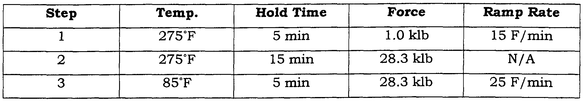
- the force of 2.9 klb corresponds to a press pressure of 100 psi. Films were finally hot pressed without vacuum to fully consolidate the composite structure, as shown below.
- the force of 28.3 klb corresponds to a press pressure of 1000 psi.
- Composite SPEMs were made with both 75 and 85% sulfonated Udel ion conducting polymers.
- SPEMs produced via this example were FMI 539-22-1, FMI 539-22-2, FMI 539-22-3. See Table X for various results obtained from SPEMs made via this procedure. _,- EXAMPLE 10 Fabrication of SPEM Using Solubilized Nafion 1100 EW
- Ion-conducting membranes fabricated in this example followed closely those in example 8.
- the substrate utilized was PBO extruded film and solvent exchanged into a mixture of water and alcohols (see below) as described above in the general procedure.
- the ion-conducting polymer used was solubilized Nafion
- Composite membranes were made by placing the exchanged films directly into the 10wt.% Nafion solutions. After twelve or more hours, these were removed and stretched into tensioning rings as described above.
- the force of 2.9 klb corresponds to a press pressure of 100 psi. Films were finally hot pressed without vacuum to fully consolidate the composite structure, as shown below.
- the force of 28.3 klb corresponds to a press pressure of 1000 psi.
- SPEMs produced via this example were FMI 126- 16N, FMI 126- 160. See Table X for various results obtained from these SPEMs.
- the low IECs obtained from these films and the correspondingly high resistances are a function of the low loading of ion-conductor in the composite structure. We expect using more concentrated solutions of the ion-conductor in imbibing the substrate will lead to composite SPEMs of low enough resistances for the applications described.
- the stability of the lateral dimensions of these Nafion based composite membranes presents a significant improvement over unsupported Nafion 117 films (which show in plane dimensional changes on hydration of about 20%). Given the exceptional strength of the PBO substrate, the mechanical properties of the composites will be well in excess of current state of the art fuel cell membranes.
- Ion-conducting membranes fabricated in this example followed closely those in example 8.
- the substrate utilized was PBO film extruded and solvent exchanged into NMP as described above in the general procedure.
- the ion-conducting polymer (75% sulfonated Ultrason purified - Na+ form) was synthesized according to example 2 given above.
- Microporous PBO having been exchanged into NMP without collapse of the pores, was added to a solution of the sulfonated 75% sulfonated Ultrason polymer in NMP (8 or 12 wt.%). After twelve or more hours at room temperature the films were removed, stretched in tensioning rings, and dried of the solvent (see general procedure outlined above). Specifically, the sulfonated Radel R / PBO films were dried in a low humidity chamber ( ⁇ 5% RH) for 1 to 2 days, vacuum dried in an oven heated from below 60°C to 140°C. ⁇
- the force of 2.9 klb corresponds to a press pressure of 100 psi. Films were finally hot pressed without vacuum to fully consolidate the composite structure, as shown below.
- the composite is preferably hot pressed.
- the hot pressing operating facilitates flow of the ion-conductor to make a homogenous composite structure.
- Non-porous teflon shims were placed on each side of the composite membrane followed by Titanium shims. The entire setup is then loaded into a press and subjected to the following cycle:
- SPEMs produced via this example were FMI 126-08E, FMI 126-08F. See Table 3 below for various results obtained from SPEMs made via this procedure.
Abstract
Description


Claims
Priority Applications (14)
| Application Number | Priority Date | Filing Date | Title |
|---|---|---|---|
| AU92101/98A AU9210198A (en) | 1997-08-29 | 1998-08-28 | Composite solid polymer electrolyte membranes |
| CA002300934A CA2300934C (en) | 1997-08-29 | 1998-08-28 | Composite solid polymer electrolyte membranes |
| EP98944594A EP1021296A4 (en) | 1997-08-29 | 1998-08-28 | Composite solid polymer electrolyte membranes |
| JP2000507525A JP2001514431A (en) | 1997-08-29 | 1998-08-28 | Composite solid polymer electrolyte membrane |
| US09/261,349 US6248469B1 (en) | 1997-08-29 | 1999-03-03 | Composite solid polymer electrolyte membranes |
| JP2000578363A JP2003503510A (en) | 1998-08-28 | 1999-08-26 | Novel ion conductive material suitable for use in electrochemical applications and related methods |
| AU23415/00A AU2341500A (en) | 1998-08-28 | 1999-08-26 | Composite solid polymer electrolyte membranes |
| CA002342221A CA2342221A1 (en) | 1998-08-28 | 1999-08-26 | Novel ion-conducting materials suitable for use in electrochemical applications and methods related thereto |
| EP99965719A EP1115769A1 (en) | 1998-08-28 | 1999-08-26 | Novel ion-conducting materials suitable for use in electrochemical applications and methods related thereto |
| PCT/US1999/019476 WO2000022684A2 (en) | 1998-08-28 | 1999-08-26 | Composite solid polymer electrolyte membranes |
| PCT/US1999/019470 WO2000024796A1 (en) | 1998-08-28 | 1999-08-26 | Novel ion-conducting materials suitable for use in electrochemical applications and methods related thereto |
| AU21424/00A AU2142400A (en) | 1998-08-28 | 1999-08-26 | Novel ion-conducting materials suitable for use in electrochemical applications and methods related thereto |
| CA002342237A CA2342237A1 (en) | 1998-08-28 | 1999-08-26 | Composite solid polymer electrolyte membranes |
| JP2000576501A JP2003528420A (en) | 1998-08-28 | 1999-08-26 | Composite solid polymer electrolyte membrane |
Applications Claiming Priority (2)
| Application Number | Priority Date | Filing Date | Title |
|---|---|---|---|
| US5723397P | 1997-08-29 | 1997-08-29 | |
| US60/057,233 | 1997-08-29 |
Related Child Applications (1)
| Application Number | Title | Priority Date | Filing Date |
|---|---|---|---|
| US09/261,349 Continuation-In-Part US6248469B1 (en) | 1997-08-29 | 1999-03-03 | Composite solid polymer electrolyte membranes |
Publications (3)
| Publication Number | Publication Date |
|---|---|
| WO1999010165A1 true WO1999010165A1 (en) | 1999-03-04 |
| WO1999010165A8 WO1999010165A8 (en) | 1999-07-22 |
| WO1999010165A9 WO1999010165A9 (en) | 1999-08-26 |
Family
ID=22009321
Family Applications (1)
| Application Number | Title | Priority Date | Filing Date |
|---|---|---|---|
| PCT/US1998/017898 WO1999010165A1 (en) | 1997-08-29 | 1998-08-28 | Composite solid polymer electrolyte membranes |
Country Status (5)
| Country | Link |
|---|---|
| EP (1) | EP1021296A4 (en) |
| JP (1) | JP2001514431A (en) |
| AU (1) | AU9210198A (en) |
| CA (1) | CA2300934C (en) |
| WO (1) | WO1999010165A1 (en) |
Cited By (42)
| Publication number | Priority date | Publication date | Assignee | Title |
|---|---|---|---|---|
| EP1202365A1 (en) * | 1999-03-08 | 2002-05-02 | Center for Advanced Science and Technology Incubation, Ltd | Electrolytic membrane for fuel cell and its manufacturing method, and fuel cell and its manufacturing method |
| WO2002059996A1 (en) * | 2001-01-26 | 2002-08-01 | Toray Industries, Inc. | Polymer electrolyte film and method for preparation of the same, and solid polymer type fuel cell using the same |
| WO2002062896A1 (en) * | 2001-02-05 | 2002-08-15 | Kaneka Corporation | Proton-conductive polymer film and process for producing the same |
| EP1263066A2 (en) * | 2001-05-25 | 2002-12-04 | Ballard Power Systems Inc. | Composite ion exchange membrane |
| WO2003001622A1 (en) * | 2001-06-25 | 2003-01-03 | Honda Giken Kogyo Kabushiki Kaisha | Electrode structure for solid-polymer type fuel cell |
| JP2003509554A (en) * | 1999-09-10 | 2003-03-11 | ビクトレックス マニュファクチャリング リミテッド | Composite ion exchange membrane |
| WO2003068853A1 (en) * | 2002-02-15 | 2003-08-21 | Toyo Boseki Kabushiki Kaisha | Cluster ion exchange membrane, and electrolyte membrane electrode connection body |
| WO2003074595A1 (en) * | 2002-03-06 | 2003-09-12 | Pemeas Gmbh | Mixture comprising sulphonic acid containing vinyl, polymer electrolyte membrane comprising polyvinylsulphonic acid and the use thereof in fuel cells |
| JP2003528212A (en) * | 2000-03-22 | 2003-09-24 | ビクトレックス マニュファクチャリング リミテッド | Ion exchange material |
| WO2004033534A1 (en) * | 2002-10-08 | 2004-04-22 | Toyo Boseki Kabushiki Kaisha | Polyarylene ether compound containing sulfonic acid group, composition containing same, and method for manufacturing those |
| WO2004037508A1 (en) * | 2002-10-24 | 2004-05-06 | Toyo Boseki Kabushiki Kaisha | Heat-resistant film and composite ion-exchange membrane |
| DE10316323A1 (en) * | 2003-04-10 | 2004-10-28 | Daimlerchrysler Ag | Functionalizing polyarylethersulfones with basic groups, for use in electrolytes, ion exchangers, catalysts, polymer electrolyte membranes or blends, involves a Grignard reaction and reaction with an anchoring compound |
| JP2005044610A (en) * | 2003-07-28 | 2005-02-17 | Toyobo Co Ltd | Composite ion-exchange membrane and its manufacturing method |
| FR2877147A1 (en) * | 2004-10-22 | 2006-04-28 | Peugeot Citroen Automobiles Sa | Ion conducting membrane, useful as polymeric solid electrolyte or proton exchanging membrane in an electrochemical device (fuel cell), comprises a micro porous structure made from a protonic conducting polymer |
| US7060735B2 (en) | 2000-02-23 | 2006-06-13 | Toyota Jidosha Kabushiki Kaisha | Polymer electrolyte membrane and method of production thereof |
| WO2007114406A1 (en) * | 2006-03-27 | 2007-10-11 | Toyota Jidosha Kabushiki Kaisha | Composite electrolyte membrane comprising imide network polymer crosslinked with strongly acidic group, method for manufacturing the composite electrolyte membrane, and fuel cell |
| US7332530B2 (en) | 2002-08-02 | 2008-02-19 | Celanese Ventures Gmbh | Proton-conducting polymer membrane comprising a polymer with sulphonic acid groups and use thereof in fuel cells |
| US7445864B2 (en) | 2002-07-06 | 2008-11-04 | Basf Fuel Cell Gmbh | Functionalized polyazoles, method for the production thereof, and use thereof |
| WO2009118612A1 (en) * | 2008-03-26 | 2009-10-01 | Toyota Jidosha Kabushiki Kaisha | Fuel cell electrolyte membrane |
| US7625652B2 (en) | 2002-04-25 | 2009-12-01 | Basf Fuel Cell Gmbh | Multilayer electrolyte membrane |
| US7649025B2 (en) | 2002-10-17 | 2010-01-19 | Toyo Boseki Kabushiki Kaisha | Composite ion-exchange membrane |
| US7736778B2 (en) | 2002-10-04 | 2010-06-15 | Basf Fuel Cell Gmbh | Proton conducting polymer membrane comprising phosphonic acid groups containing polyazoles and the use thereof in fuel cells |
| US7745030B2 (en) | 2002-10-04 | 2010-06-29 | Basf Fuel Cell Gmbh | Proton-conducting polymer membrane comprising sulfonic acid-containing polyazoles, and use thereof in fuel cells |
| US7785751B2 (en) | 2004-12-03 | 2010-08-31 | Nitto Denko Corporation | Production method of electrolyte membrane, electrolyte membrane and solid polymer fuel cell using same |
| US7795372B2 (en) | 2002-08-29 | 2010-09-14 | Basf Fuel Cell Gmbh | Polymer film based on polyazoles, and uses thereof |
| US7820314B2 (en) | 2003-07-27 | 2010-10-26 | Basf Fuel Cell Research Gmbh | Proton-conducting membrane and use thereof |
| US7833676B2 (en) | 2004-07-09 | 2010-11-16 | Nissan Motor Co., Ltd. | Fuel cell system and solid polymer electrolyte film |
| US7846982B2 (en) | 2002-03-06 | 2010-12-07 | Pemeas Gmbh | Proton conducting electrolyte membrane having reduced methanol permeability and the use thereof in fuel cells |
| US7846983B2 (en) | 2002-03-05 | 2010-12-07 | Basf Fuel Cell Gmbh | Proton conducting electrolyte membrane for use in high temperatures and the use thereof in fuel cells |
| US7846610B2 (en) | 2006-10-23 | 2010-12-07 | Canon Kabushiki Kaisha | Electrolyte membrane, production method thereof, and fuel cell |
| DE102009035759A1 (en) * | 2009-07-27 | 2011-02-03 | Varta Microbattery Gmbh | Galvanic element and separator with improved safety features |
| US8551637B2 (en) | 2004-05-04 | 2013-10-08 | Societe Bic | Membranes and electrochemical cells incorporating such membranes |
| DE112004001057B4 (en) * | 2003-06-27 | 2014-06-05 | Asahi Kasei Chemicals Corp. | High strength polymer electrolyte membrane, process for its preparation and use |
| US9017892B2 (en) | 2004-05-04 | 2015-04-28 | Societe Bic | Electrochemical cells having current-carrying structures underlying electrochemical reaction layers |
| US9472817B2 (en) | 2008-02-29 | 2016-10-18 | Intelligent Energy Limited | Electrochemical cell and membranes related thereto |
| US9673476B2 (en) | 2007-09-25 | 2017-06-06 | Intelligent Energy Limited | Fuel cell systems including space-saving fluid plenum and related methods |
| US9893373B2 (en) | 2010-05-25 | 2018-02-13 | 3M Innovative Properties Company | Reinforced electrolyte membrane |
| US9911984B2 (en) | 2014-06-17 | 2018-03-06 | Medtronic, Inc. | Semi-solid electrolytes for batteries |
| US10333173B2 (en) | 2014-11-14 | 2019-06-25 | Medtronic, Inc. | Composite separator and electrolyte for solid state batteries |
| US10587005B2 (en) | 2016-03-30 | 2020-03-10 | Wildcat Discovery Technologies, Inc. | Solid electrolyte compositions |
| CN114288855A (en) * | 2021-11-25 | 2022-04-08 | 国家电投集团氢能科技发展有限公司 | Water electrolysis membrane and preparation method thereof |
| CN115418673A (en) * | 2022-08-29 | 2022-12-02 | 中国华能集团清洁能源技术研究院有限公司 | Seawater PEM (proton exchange membrane) electrolytic hydrogen production system and method based on proton exchange membrane |
Families Citing this family (24)
| Publication number | Priority date | Publication date | Assignee | Title |
|---|---|---|---|---|
| US6248469B1 (en) * | 1997-08-29 | 2001-06-19 | Foster-Miller, Inc. | Composite solid polymer electrolyte membranes |
| US6828353B1 (en) * | 1998-09-11 | 2004-12-07 | Victrex Manufacturing Limited | Ion-exchange polymers |
| US20040036394A1 (en) * | 2002-08-21 | 2004-02-26 | 3M Innovative Properties Company | Process for preparing multi-layer proton exchange membranes and membrane electrode assemblies |
| DE10301810A1 (en) * | 2003-01-20 | 2004-07-29 | Sartorius Ag | Membrane electrode array for high temperature polymer electrolyte fuel cell, e.g. for road vehicle, spacecraft or power station, has basic polymer membrane between flat gas distribution electrodes acting as membrane dopant reservoir |
| JP4496718B2 (en) * | 2003-06-06 | 2010-07-07 | 宇部興産株式会社 | POLYMER ELECTROLYTE MEMBRANE AND METHOD FOR PRODUCING THE SAME |
| CN1833330B (en) * | 2003-07-31 | 2010-11-03 | 东洋纺织株式会社 | Electrolyte membrane-electrode assembly, fuel cell using same, and method for producing electrolyte membrane-electrode assembly |
| JP2005048022A (en) * | 2003-07-31 | 2005-02-24 | Toyobo Co Ltd | Composite ion-exchange membrane and method for producing the same |
| JP4604469B2 (en) * | 2003-08-06 | 2011-01-05 | 東洋紡績株式会社 | Porous membrane, method for producing the same, and apparatus |
| JP4766829B2 (en) * | 2003-08-07 | 2011-09-07 | 株式会社豊田中央研究所 | Solid polymer electrolyte membrane and solid polymer fuel cell |
| DE10340927A1 (en) * | 2003-09-04 | 2005-03-31 | Celanese Ventures Gmbh | Proton-conducting polymer membrane comprising polymers having covalently bonded to aromatic groups sulfonic acid groups, membrane-electrode unit and their application in fuel cells |
| WO2005086264A1 (en) * | 2004-03-04 | 2005-09-15 | Matsushita Electric Industrial Co., Otd. | Composite electrolytic membrane, catalytic layer membrane assembly, membrane electrode assembly and polymer electroytic fuel cell |
| EP1788654B1 (en) | 2004-09-09 | 2011-11-16 | Asahi Kasei Chemicals Corporation | Solid polymer electrolyte membrane and method for producing same |
| JP4895563B2 (en) * | 2004-09-30 | 2012-03-14 | 旭化成イーマテリアルズ株式会社 | Reinforced polymer electrolyte membrane |
| JP2006338929A (en) * | 2005-05-31 | 2006-12-14 | Hitachi Chem Co Ltd | Reinforced polyelectrolyte, electrode-polyelectrolyte membrane assembly, fuel cell, and method of manufacturing them |
| JP2006338928A (en) * | 2005-05-31 | 2006-12-14 | Hitachi Chem Co Ltd | Reinforced polyelectrolyte, electrode-polyelectrolyte membrane assembly, and fuel cell as well as method of manufacturing them |
| JP5061385B2 (en) * | 2005-12-08 | 2012-10-31 | 株式会社ノリタケカンパニーリミテド | Solid electrolyte |
| WO2008023632A1 (en) * | 2006-08-22 | 2008-02-28 | Kabushiki Kaisha Toshiba | Membrane electrode assembly, method for producing the same, and fuel cell |
| JP5247113B2 (en) * | 2006-10-23 | 2013-07-24 | キヤノン株式会社 | Electrolyte membrane, method for producing electrolyte membrane, and fuel cell |
| US7740942B2 (en) * | 2006-12-13 | 2010-06-22 | General Electric Company | Opto-electronic devices containing sulfonated copolymers |
| DE112010003385T5 (en) * | 2009-08-25 | 2012-06-06 | Kolon Fashion Material, Inc. | Polymer electrolyte membrane for a fuel cell and method for its manufacture |
| US7810652B2 (en) * | 2009-09-25 | 2010-10-12 | Uop Llc | Method to improve the selectivity of polybenzoxazole membranes |
| CN103563142B (en) * | 2011-03-29 | 2016-10-05 | 科学与工业研究委员会 | Prepare the modification method of membrane electrode assembly (MEA) |
| JP6135914B2 (en) * | 2013-03-28 | 2017-05-31 | Dic株式会社 | Polyarylene sulfide resin porous body and method for producing the same |
| FR3049605B1 (en) * | 2016-04-05 | 2018-03-23 | Arkema France | PROCESS FOR OBTAINING FINE FILMS AND FILMOGENIC ARTICLES |
Citations (3)
| Publication number | Priority date | Publication date | Assignee | Title |
|---|---|---|---|---|
| US5422411A (en) * | 1993-09-21 | 1995-06-06 | Ballard Power Systems Inc. | Trifluorostyrene and substituted trifluorostyrene copolymeric compositions and ion-exchange membranes formed therefrom |
| US5547551A (en) * | 1995-03-15 | 1996-08-20 | W. L. Gore & Associates, Inc. | Ultra-thin integral composite membrane |
| US5599614A (en) * | 1995-03-15 | 1997-02-04 | W. L. Gore & Associates, Inc. | Integral composite membrane |
Family Cites Families (6)
| Publication number | Priority date | Publication date | Assignee | Title |
|---|---|---|---|---|
| JPS55137005A (en) * | 1979-04-13 | 1980-10-25 | Teijin Ltd | Selectively permeable composite membrane and preparing the same |
| JPS59120211A (en) * | 1982-12-28 | 1984-07-11 | Asahi Glass Co Ltd | Preparation of composite membrane |
| EP0227299A3 (en) * | 1985-12-20 | 1987-10-07 | The Standard Oil Company | Polymer/liquid crystal composite semipermeable membranes and process for the use thereof |
| US4714663A (en) * | 1986-10-14 | 1987-12-22 | The United States Of America As Represented By The United States Department Of Energy | Sulfonated polysulfone battery membrane for use in corrosive environments |
| JP2694341B2 (en) * | 1987-02-04 | 1997-12-24 | ハイドロノーティクス | Improved oxidation resistant film and method of manufacturing the same |
| US4865930A (en) * | 1988-10-27 | 1989-09-12 | Hughes Aircraft Company | Method for forming a gas-permeable and ion-permeable membrane |
-
1998
- 1998-08-28 CA CA002300934A patent/CA2300934C/en not_active Expired - Fee Related
- 1998-08-28 EP EP98944594A patent/EP1021296A4/en not_active Withdrawn
- 1998-08-28 AU AU92101/98A patent/AU9210198A/en not_active Abandoned
- 1998-08-28 JP JP2000507525A patent/JP2001514431A/en active Pending
- 1998-08-28 WO PCT/US1998/017898 patent/WO1999010165A1/en active Application Filing
Patent Citations (3)
| Publication number | Priority date | Publication date | Assignee | Title |
|---|---|---|---|---|
| US5422411A (en) * | 1993-09-21 | 1995-06-06 | Ballard Power Systems Inc. | Trifluorostyrene and substituted trifluorostyrene copolymeric compositions and ion-exchange membranes formed therefrom |
| US5547551A (en) * | 1995-03-15 | 1996-08-20 | W. L. Gore & Associates, Inc. | Ultra-thin integral composite membrane |
| US5599614A (en) * | 1995-03-15 | 1997-02-04 | W. L. Gore & Associates, Inc. | Integral composite membrane |
Non-Patent Citations (1)
| Title |
|---|
| See also references of EP1021296A4 * |
Cited By (60)
| Publication number | Priority date | Publication date | Assignee | Title |
|---|---|---|---|---|
| US7344791B1 (en) | 1999-03-08 | 2008-03-18 | Toudai Tlo, Ltd. | Electrolytic membrane for fuel cell and its manufacturing method, and fuel cell and its manufacturing method |
| EP1202365A1 (en) * | 1999-03-08 | 2002-05-02 | Center for Advanced Science and Technology Incubation, Ltd | Electrolytic membrane for fuel cell and its manufacturing method, and fuel cell and its manufacturing method |
| EP1202365A4 (en) * | 1999-03-08 | 2006-03-15 | Toudai Tlo Ltd | Electrolytic membrane for fuel cell and its manufacturing method, and fuel cell and its manufacturing method |
| JP2003509554A (en) * | 1999-09-10 | 2003-03-11 | ビクトレックス マニュファクチャリング リミテッド | Composite ion exchange membrane |
| JP4647167B2 (en) * | 1999-09-10 | 2011-03-09 | ビクトレックス マニュファクチャリング リミテッド | Composite ion exchange membrane |
| US7060735B2 (en) | 2000-02-23 | 2006-06-13 | Toyota Jidosha Kabushiki Kaisha | Polymer electrolyte membrane and method of production thereof |
| JP2003528212A (en) * | 2000-03-22 | 2003-09-24 | ビクトレックス マニュファクチャリング リミテッド | Ion exchange material |
| WO2002059996A1 (en) * | 2001-01-26 | 2002-08-01 | Toray Industries, Inc. | Polymer electrolyte film and method for preparation of the same, and solid polymer type fuel cell using the same |
| WO2002062896A1 (en) * | 2001-02-05 | 2002-08-15 | Kaneka Corporation | Proton-conductive polymer film and process for producing the same |
| EP1263066A2 (en) * | 2001-05-25 | 2002-12-04 | Ballard Power Systems Inc. | Composite ion exchange membrane |
| US6689501B2 (en) | 2001-05-25 | 2004-02-10 | Ballard Power Systems Inc. | Composite ion exchange membrane for use in a fuel cell |
| EP1263066A3 (en) * | 2001-05-25 | 2005-10-19 | Ballard Power Systems Inc. | Composite ion exchange membrane |
| WO2003001622A1 (en) * | 2001-06-25 | 2003-01-03 | Honda Giken Kogyo Kabushiki Kaisha | Electrode structure for solid-polymer type fuel cell |
| US7445867B2 (en) | 2001-06-25 | 2008-11-04 | Honda Giken Kogyo Kabushiki Kaisha | Electrode structure for solid-polymer type fuel cell |
| US7537852B2 (en) | 2002-02-15 | 2009-05-26 | Toyo Boseki Kabushiki Kaisha | Composite ion exchange membrane and electrolyte membrane electrode assembly |
| WO2003068853A1 (en) * | 2002-02-15 | 2003-08-21 | Toyo Boseki Kabushiki Kaisha | Cluster ion exchange membrane, and electrolyte membrane electrode connection body |
| US7846983B2 (en) | 2002-03-05 | 2010-12-07 | Basf Fuel Cell Gmbh | Proton conducting electrolyte membrane for use in high temperatures and the use thereof in fuel cells |
| US7846982B2 (en) | 2002-03-06 | 2010-12-07 | Pemeas Gmbh | Proton conducting electrolyte membrane having reduced methanol permeability and the use thereof in fuel cells |
| CN1318484C (en) * | 2002-03-06 | 2007-05-30 | 佩密斯股份有限公司 | Mixture comprising sulphonic acid containing vinyl, polymer electrolyte membrane comprising polyvinylsulphonic acid and the use thereof in fuel cells |
| WO2003074595A1 (en) * | 2002-03-06 | 2003-09-12 | Pemeas Gmbh | Mixture comprising sulphonic acid containing vinyl, polymer electrolyte membrane comprising polyvinylsulphonic acid and the use thereof in fuel cells |
| US7625652B2 (en) | 2002-04-25 | 2009-12-01 | Basf Fuel Cell Gmbh | Multilayer electrolyte membrane |
| US7445864B2 (en) | 2002-07-06 | 2008-11-04 | Basf Fuel Cell Gmbh | Functionalized polyazoles, method for the production thereof, and use thereof |
| US7332530B2 (en) | 2002-08-02 | 2008-02-19 | Celanese Ventures Gmbh | Proton-conducting polymer membrane comprising a polymer with sulphonic acid groups and use thereof in fuel cells |
| US7795372B2 (en) | 2002-08-29 | 2010-09-14 | Basf Fuel Cell Gmbh | Polymer film based on polyazoles, and uses thereof |
| US7745030B2 (en) | 2002-10-04 | 2010-06-29 | Basf Fuel Cell Gmbh | Proton-conducting polymer membrane comprising sulfonic acid-containing polyazoles, and use thereof in fuel cells |
| US7736778B2 (en) | 2002-10-04 | 2010-06-15 | Basf Fuel Cell Gmbh | Proton conducting polymer membrane comprising phosphonic acid groups containing polyazoles and the use thereof in fuel cells |
| WO2004033534A1 (en) * | 2002-10-08 | 2004-04-22 | Toyo Boseki Kabushiki Kaisha | Polyarylene ether compound containing sulfonic acid group, composition containing same, and method for manufacturing those |
| US7754844B2 (en) | 2002-10-08 | 2010-07-13 | Toyo Boseki Kabushiki Kaisha | Polyarylene ether compound containing sulfonic acid group, composition containing same, and method for manufacturing those |
| US7649025B2 (en) | 2002-10-17 | 2010-01-19 | Toyo Boseki Kabushiki Kaisha | Composite ion-exchange membrane |
| AU2003275623B8 (en) * | 2002-10-24 | 2009-03-12 | Toyo Boseki Kabushiki Kaisha | Heat-resistant film and composite ion-exchange membrane |
| WO2004037508A1 (en) * | 2002-10-24 | 2004-05-06 | Toyo Boseki Kabushiki Kaisha | Heat-resistant film and composite ion-exchange membrane |
| AU2003275623B2 (en) * | 2002-10-24 | 2009-02-05 | Toyo Boseki Kabushiki Kaisha | Heat-resistant film and composite ion-exchange membrane |
| DE10316323A1 (en) * | 2003-04-10 | 2004-10-28 | Daimlerchrysler Ag | Functionalizing polyarylethersulfones with basic groups, for use in electrolytes, ion exchangers, catalysts, polymer electrolyte membranes or blends, involves a Grignard reaction and reaction with an anchoring compound |
| DE112004001057B4 (en) * | 2003-06-27 | 2014-06-05 | Asahi Kasei Chemicals Corp. | High strength polymer electrolyte membrane, process for its preparation and use |
| US7820314B2 (en) | 2003-07-27 | 2010-10-26 | Basf Fuel Cell Research Gmbh | Proton-conducting membrane and use thereof |
| US8323810B2 (en) | 2003-07-27 | 2012-12-04 | Basf Fuel Cell Research Gmbh | Proton-conducting membrane and use thereof |
| JP2005044610A (en) * | 2003-07-28 | 2005-02-17 | Toyobo Co Ltd | Composite ion-exchange membrane and its manufacturing method |
| US9017892B2 (en) | 2004-05-04 | 2015-04-28 | Societe Bic | Electrochemical cells having current-carrying structures underlying electrochemical reaction layers |
| US8551637B2 (en) | 2004-05-04 | 2013-10-08 | Societe Bic | Membranes and electrochemical cells incorporating such membranes |
| US8252481B2 (en) | 2004-07-09 | 2012-08-28 | Nissan Motor Co., Ltd. | Fuel cell system and solid polymer electrolyte film |
| US7833676B2 (en) | 2004-07-09 | 2010-11-16 | Nissan Motor Co., Ltd. | Fuel cell system and solid polymer electrolyte film |
| FR2877147A1 (en) * | 2004-10-22 | 2006-04-28 | Peugeot Citroen Automobiles Sa | Ion conducting membrane, useful as polymeric solid electrolyte or proton exchanging membrane in an electrochemical device (fuel cell), comprises a micro porous structure made from a protonic conducting polymer |
| US7785751B2 (en) | 2004-12-03 | 2010-08-31 | Nitto Denko Corporation | Production method of electrolyte membrane, electrolyte membrane and solid polymer fuel cell using same |
| WO2007114406A1 (en) * | 2006-03-27 | 2007-10-11 | Toyota Jidosha Kabushiki Kaisha | Composite electrolyte membrane comprising imide network polymer crosslinked with strongly acidic group, method for manufacturing the composite electrolyte membrane, and fuel cell |
| US7846610B2 (en) | 2006-10-23 | 2010-12-07 | Canon Kabushiki Kaisha | Electrolyte membrane, production method thereof, and fuel cell |
| US9673476B2 (en) | 2007-09-25 | 2017-06-06 | Intelligent Energy Limited | Fuel cell systems including space-saving fluid plenum and related methods |
| US9472817B2 (en) | 2008-02-29 | 2016-10-18 | Intelligent Energy Limited | Electrochemical cell and membranes related thereto |
| US20110207021A1 (en) * | 2008-03-26 | 2011-08-25 | Toyota Jidosha Kabushiki Kaisha | Fuel cell electrolyte membrane |
| WO2009118612A1 (en) * | 2008-03-26 | 2009-10-01 | Toyota Jidosha Kabushiki Kaisha | Fuel cell electrolyte membrane |
| DE102009035759A1 (en) * | 2009-07-27 | 2011-02-03 | Varta Microbattery Gmbh | Galvanic element and separator with improved safety features |
| US9893373B2 (en) | 2010-05-25 | 2018-02-13 | 3M Innovative Properties Company | Reinforced electrolyte membrane |
| US9911984B2 (en) | 2014-06-17 | 2018-03-06 | Medtronic, Inc. | Semi-solid electrolytes for batteries |
| US10727499B2 (en) | 2014-06-17 | 2020-07-28 | Medtronic, Inc. | Semi-solid electrolytes for batteries |
| US10333173B2 (en) | 2014-11-14 | 2019-06-25 | Medtronic, Inc. | Composite separator and electrolyte for solid state batteries |
| US11437649B2 (en) | 2014-11-14 | 2022-09-06 | Medtronic, Inc. | Composite separator and electrolyte for solid state batteries |
| US10587005B2 (en) | 2016-03-30 | 2020-03-10 | Wildcat Discovery Technologies, Inc. | Solid electrolyte compositions |
| CN114288855A (en) * | 2021-11-25 | 2022-04-08 | 国家电投集团氢能科技发展有限公司 | Water electrolysis membrane and preparation method thereof |
| CN114288855B (en) * | 2021-11-25 | 2023-03-10 | 国家电投集团氢能科技发展有限公司 | Water electrolysis membrane and preparation method thereof |
| CN115418673A (en) * | 2022-08-29 | 2022-12-02 | 中国华能集团清洁能源技术研究院有限公司 | Seawater PEM (proton exchange membrane) electrolytic hydrogen production system and method based on proton exchange membrane |
| CN115418673B (en) * | 2022-08-29 | 2023-09-19 | 中国华能集团清洁能源技术研究院有限公司 | Seawater PEM electrolytic hydrogen production system and method based on proton exchange membrane |
Also Published As
| Publication number | Publication date |
|---|---|
| EP1021296A4 (en) | 2001-05-23 |
| WO1999010165A9 (en) | 1999-08-26 |
| CA2300934A1 (en) | 1999-03-04 |
| AU9210198A (en) | 1999-03-16 |
| WO1999010165A8 (en) | 1999-07-22 |
| JP2001514431A (en) | 2001-09-11 |
| EP1021296A1 (en) | 2000-07-26 |
| CA2300934C (en) | 2008-08-26 |
Similar Documents
| Publication | Publication Date | Title |
|---|---|---|
| US6248469B1 (en) | Composite solid polymer electrolyte membranes | |
| CA2300934C (en) | Composite solid polymer electrolyte membranes | |
| US7550216B2 (en) | Composite solid polymer electrolyte membranes | |
| CA2402840C (en) | Composite ion exchange material | |
| Savadogo | Emerging membranes for electrochemical systems: Part II. High temperature composite membranes for polymer electrolyte fuel cell (PEFC) applications | |
| CA2567783A1 (en) | Solid polymer electrolyte membranes | |
| WO2000024796A1 (en) | Novel ion-conducting materials suitable for use in electrochemical applications and methods related thereto | |
| WO2011046233A1 (en) | Polymer electrolyte membrane, membrane-electrode assembly, and solid polymer fuel cell | |
| WO2005000949A9 (en) | Polymer electrolyte membrane with high durability and method for producing same | |
| KR102295383B1 (en) | Polymer electrolyte membrane, membrane electrode assembly, and polymer electrolyte fuel cell | |
| CA2402841C (en) | Ion exchange materials | |
| AU778365B2 (en) | Composite ion-exchange membranes | |
| KR101315744B1 (en) | Multi layer reinfored electrolyte membrane for solid polymer fuel cell, manufacturing method thereof, membrane-electrode assembly having the same and fuel cell having them | |
| Liu et al. | Proton conductivity of aromatic polymers | |
| EP1116292A2 (en) | Composite solid polymer electrolyte membranes | |
| Ye et al. | Membrane Materials for Vanadium Redox Flow Battery | |
| Wang | High Free Volume Ion-Containing Polysulfone Membranes for Fuel Cells and Water Purification Applications | |
| Helen et al. | Strategies for the design of membranes for fuel cells | |
| Wiles | High performance disulfonated poly (arylene sulfone) co-and terpolymers for proton exchange membranes for fuel cell and transducer applications: Synthesis, characterization and fabrication of ion conducting membranes | |
| Korin et al. | Fuel cells and ionically conductive membranes: an overview | |
| WO2008144660A2 (en) | Chemically cross linked ionomer membrane |
Legal Events
| Date | Code | Title | Description |
|---|---|---|---|
| AK | Designated states |
Kind code of ref document: A1 Designated state(s): AL AM AT AU AZ BA BB BG BR BY CA CH CN CU CZ DE DK EE ES FI GB GE GH GM HU ID IL IS JP KE KG KP KR KZ LC LK LR LS LT LU LV MD MG MK MN MW MX NO NZ PL PT RO RU SD SE SG SI SK SL TJ TM TR TT UA UG US UZ VN YU ZW |
|
| AL | Designated countries for regional patents |
Kind code of ref document: A1 Designated state(s): GH GM KE LS MW SD SZ UG ZW AM AZ BY KG KZ MD RU TJ TM AT BE CH CY DE DK ES FI FR GB GR IE IT LU MC NL PT SE BF BJ CF CG CI CM GA GN GW ML MR NE SN TD TG |
|
| 121 | Ep: the epo has been informed by wipo that ep was designated in this application | ||
| DFPE | Request for preliminary examination filed prior to expiration of 19th month from priority date (pct application filed before 20040101) | ||
| AK | Designated states |
Kind code of ref document: C1 Designated state(s): AL AM AT AU AZ BA BB BG BR BY CA CH CN CU CZ DE DK EE ES FI GB GE GH GM HR HU ID IL IS JP KE KG KP KR KZ LC LK LR LS LT LU LV MD MG MK MN MW MX NO NZ PL PT RO RU SD SE SG SI SK SL TJ TM TR TT UA UG US UZ VN YU ZW |
|
| AL | Designated countries for regional patents |
Kind code of ref document: C1 Designated state(s): GH GM KE LS MW SD SZ UG ZW AM AZ BY KG KZ MD RU TJ TM AT BE CH CY DE DK ES FI FR GB GR IE IT LU MC NL PT SE BF BJ CF CG CI CM GA GN GW ML MR NE SN TD TG |
|
| CFP | Corrected version of a pamphlet front page | ||
| CR1 | Correction of entry in section i |
Free format text: PAT. BUL. 09/99 UNDER (81) ADD "HR"; DUE TO LATE TRANSMITTAL BY THE RECEIVING OFFICE |
|
| AK | Designated states |
Kind code of ref document: C2 Designated state(s): AL AM AT AU AZ BA BB BG BR BY CA CH CN CU CZ DE DK EE ES FI GB GE GH GM HR HU ID IL IS JP KE KG KP KR KZ LC LK LR LS LT LU LV MD MG MK MN MW MX NO NZ PL PT RO RU SD SE SG SI SK SL TJ TM TR TT UA UG US UZ VN YU ZW |
|
| AL | Designated countries for regional patents |
Kind code of ref document: C2 Designated state(s): GH GM KE LS MW SD SZ UG ZW AM AZ BY KG KZ MD RU TJ TM AT BE CH CY DE DK ES FI FR GB GR IE IT LU MC NL PT SE BF BJ CF CG CI CM GA GN GW ML MR NE SN TD TG |
|
| COP | Corrected version of pamphlet |
Free format text: PAGES 1-57, DESCRIPTION, REPLACED BY NEW PAGES 1-58; PAGES 58-64, CLAIMS, REPLACED BY NEW PAGES 59-65; PAGES 1/2-2/2, DRAWINGS, REPLACED BY NEW PAGES 1/2-2/2; DUE TO LATE TRANSMITTAL BY THE RECEIVING OFFICE |
|
| ENP | Entry into the national phase |
Ref document number: 2300934 Country of ref document: CA Ref country code: CA Ref document number: 2300934 Kind code of ref document: A Format of ref document f/p: F |
|
| ENP | Entry into the national phase |
Ref country code: JP Ref document number: 2000 507525 Kind code of ref document: A Format of ref document f/p: F |
|
| NENP | Non-entry into the national phase |
Ref country code: KR |
|
| WWE | Wipo information: entry into national phase |
Ref document number: 1998944594 Country of ref document: EP |
|
| REG | Reference to national code |
Ref country code: DE Ref legal event code: 8642 |
|
| WWP | Wipo information: published in national office |
Ref document number: 1998944594 Country of ref document: EP |