WO2001031816A1 - System and method for encoding an audio signal for use in broadcast program identification systems, by adding inaudible codes to the audio signal - Google Patents

System and method for encoding an audio signal for use in broadcast program identification systems, by adding inaudible codes to the audio signal Download PDF

Info

Publication number
WO2001031816A1
WO2001031816A1 PCT/US2000/003829 US0003829W WO0131816A1 WO 2001031816 A1 WO2001031816 A1 WO 2001031816A1 US 0003829 W US0003829 W US 0003829W WO 0131816 A1 WO0131816 A1 WO 0131816A1
Authority
WO
WIPO (PCT)
Prior art keywords
audio
frequency
block
frequencies
blocks
Prior art date
Application number
PCT/US2000/003829
Other languages
French (fr)
Inventor
Venugopal Srinivasan
Original Assignee
Nielsen Media Research, Inc.
Priority date (The priority date is an assumption and is not a legal conclusion. Google has not performed a legal analysis and makes no representation as to the accuracy of the date listed.)
Filing date
Publication date
Priority claimed from US09/428,425 external-priority patent/US7006555B1/en
Application filed by Nielsen Media Research, Inc. filed Critical Nielsen Media Research, Inc.
Priority to EP00907291A priority Critical patent/EP1277295A1/en
Priority to AU28813/00A priority patent/AU2881300A/en
Publication of WO2001031816A1 publication Critical patent/WO2001031816A1/en

Links

Classifications

    • HELECTRICITY
    • H04ELECTRIC COMMUNICATION TECHNIQUE
    • H04HBROADCAST COMMUNICATION
    • H04H20/00Arrangements for broadcast or for distribution combined with broadcast
    • H04H20/28Arrangements for simultaneous broadcast of plural pieces of information
    • H04H20/30Arrangements for simultaneous broadcast of plural pieces of information by a single channel
    • H04H20/31Arrangements for simultaneous broadcast of plural pieces of information by a single channel using in-band signals, e.g. subsonic or cue signal
    • HELECTRICITY
    • H04ELECTRIC COMMUNICATION TECHNIQUE
    • H04HBROADCAST COMMUNICATION
    • H04H60/00Arrangements for broadcast applications with a direct linking to broadcast information or broadcast space-time; Broadcast-related systems
    • H04H60/35Arrangements for identifying or recognising characteristics with a direct linkage to broadcast information or to broadcast space-time, e.g. for identifying broadcast stations or for identifying users
    • H04H60/37Arrangements for identifying or recognising characteristics with a direct linkage to broadcast information or to broadcast space-time, e.g. for identifying broadcast stations or for identifying users for identifying segments of broadcast information, e.g. scenes or extracting programme ID
    • HELECTRICITY
    • H04ELECTRIC COMMUNICATION TECHNIQUE
    • H04HBROADCAST COMMUNICATION
    • H04H2201/00Aspects of broadcast communication
    • H04H2201/50Aspects of broadcast communication characterised by the use of watermarks

Definitions

  • the present invention relates to spectral audio encoding useful, for example, in modulating broadcast signals in order to add identifying codes thereto.
  • the reference site could be the viewer's household, the reference site is usually at a location which is remote from the households of all of the viewers being monitored.
  • Systems using signature extraction are taught by Lert and u in U.S. Patent No. 4,677,466 and by Kiewit and Lu in U.S. Patent No. 4,697,209.
  • audio characteristic signatures are often utilized.
  • these characteristic signatures are extracted by a unit located at the monitored receiver, sometimes referred to as a site unit.
  • the site unit monitors the audio output of a television or radio receiver either by means of a microphone that picks up the sound from the speakers of the monitored receiver or by means of an output line from the monitored receiver.
  • the site unit extracts and transmits the characteristic signatures to a central household unit, sometimes referred to as a home unit.
  • Each characteristic signature is designed to uniquely characterize the audio signal tuned by the receiver during the time of signature extraction.
  • Characteristic signatures are typically transmitted from the home unit to a central office where a matching operation is performed between the characteristic signatures and a set of reference signatures extracted at a reference site from all of the audio channels that could have been tuned by the receiver in the household being monitored.
  • a matching score is computed by a matching algorithm and is used to determine the identity of the program to which the monitored receiver was tuned or the program source (such as a broadcaster) of the tuned program.
  • Yet another approach to metering video and/or audio tuned by televisions and/or radios is to add ancillary identification codes to television and/or radio programs and to detect and decode the ancillary codes in order to identify the encoded programs or the corresponding program sources when the programs are tuned by monitored receivers.
  • Preuss et al . in U.S. Patent No. 5,319,735, teach a multi-band audio encoding arrangement in which a spread spectrum code is inserted in recorded music at a fixed ratio to the input signal intensity (code-to-music ratio) that is preferably 19 dB .
  • Lee et al . in U.S. Patent No. 5,687,191, teach an audio coding arrangement suitable for use with digitized audio signals in which the code intensity is made to match the input signal by calculating a signal-to- mask ratio in each of several frequency bands and by then inserting the code at an intensity that is a predetermined ratio of the audio input in that band.
  • Lee et al . have also described a method of embedding digital information in a digital waveform in pending U.S. application Serial No. 08/524,132.
  • ancillary codes are preferably inserted at low intensities in order to prevent the code from distracting a listener of program audio, such codes may be vulnerable to various signal processing operations.
  • Lee et al . discuss digitized audio signals, it may be noted that many of the earlier known approaches to encoding an audio signal are not compatible with current and proposed digital audio standards, particularly those employing signal compression methods that may reduce the signal's dynamic range (and thereby delete a low level code) or that otherwise may damage an ancillary code.
  • an ancillary code it is particularly important for an ancillary code to survive compression and subsequent de-compression by the AC-3 algorithm or by one of the algorithms recommended in the ISO/IEC 11172 MPEG standard, which is expected to be widely used in future digital television transmission and reception systems .
  • U.S. Patent Application Serial No. 09/116,397 filed July 16, 1998 discloses a system and method for inserting a code into an audio signal so that the code is likely to survive compression and decompression as required by current and proposed digital audio standards.
  • spectral modulation at selected code frequencies is used to insert the code into the audio signal .
  • These code frequencies are varied from audio block to audio block, and the spectral modulation may be implemented as amplitude modulation, modulation by frequency swapping, phase modulation, and/or odd/even index modulation.
  • a code inserted by spectral modulation in accordance with the aforementioned patent application is substantially inaudible. However, there are some instances where the code may be undesirably audible.
  • the present invention addresses one or more of these instances.
  • the present application also addresses methods of multi-level coding.
  • a method for encoding first and second blocks of audio with corresponding first and second binary code bits comprises the following steps: a) selecting first and second frequencies from a frequency spectrum of the first block of audio; b) modulating the audio based upon the first and second frequen- cies to thereby encode the first block of audio with the first binary code bit; c) selecting third and fourth frequencies from a frequency spectrum of the second block of audio, wherein the third and fourth frequencies bear a predetermined offset relationship to the first and second frequencies; and, d) modulating the audio based upon the third and fourth frequencies to thereby encode the second block of audio with the second binary code bit .
  • a method for encoding a block of audio with a binary code bit comprises the following steps: a) selecting a frequency from a frequency spectrum of the block of audio; b) selectively amplifying an odd index frequency in a neighborhood of the selected frequency to be a local maximum if the block of audio is to be encoded with the binary code bit having a first value; and, c) selectively amplifying an even index frequency in a neighborhood of the selected frequency to be a local maximum if the block of audio is to be encoded with the binary code bit having a second value.
  • a method for encoding blocks of audio with binary code bits comprises the following steps: a) determining an audio quality measure AQM for each block of audio; b) comparing the AQM corresponding to each block of audio to AQM THRESH , wherein AQM THRESH is a predetermined audio quality measure reference; c) if AQM ⁇ AQM THRESH for x blocks of audio out of y blocks of audio, encoding the blocks of audio with binary bits, wherein x and y are corresponding predetermined numbers of blocks of audio; and, d) if AQM > AQM THRESH for the x blocks of audio out of the y blocks of audio, suspending encoding of the blocks of audio.
  • a method to encode a block of audio with a binary code bit.
  • the block of audio has an energy.
  • the method comprises the following steps: a) determining a ratio E 1 /E 2 , wherein E is the energy in a first portion of the block of audio, and wherein E 2 is the energy in a second portion of the block of audio; b) modulating the block of audio with the binary code bit if E- L /E 2 > E PRE , wherein E PRE is a predetermined reference; and, c) not modulating the block of audio with the binary code bit if E- L /E 2 ⁇ E PRE .
  • a method of encoding blocks of audio with binary code bits comprises the following steps: a) encoding each of the blocks of audio with a binary bit by modulating the audio within the corresponding block of audio at selected first and second frequencies, wherein the selected first and second frequencies are hopped from block to block; and, b) executing step a) so as to indicate first and second levels of distribution of the audio.
  • a method for decoding first and second blocks of audio in order to recover corresponding first and second binary code bits therefrom comprises the following steps: a) detecting first and second frequencies from a frequency spec- trum of the first block of audio; b) demodulating the first and second frequencies in order to recover to the first binary code bit; c) detecting third and fourth frequencies from a frequency spectrum of the second block of audio, wherein the third and fourth frequencies bear a predetermined offset relationship to the first and second frequencies; and, d) demodulating the third and fourth frequencies in order to recover the second binary code bit .
  • a method of decoding blocks of audio encoded with binary code bits comprises the following steps: a) decoding each of the blocks of audio in order to recover a corresponding binary bit by demodulating the audio within the corresponding block of audio at selected first and second frequencies, wherein the selected first and second frequencies are hopped from block to block; and, b) executing step a) so as identify first and second distributors of the audio.
  • a method of decoding a block of audio in order to re- cover a binary code bit therefrom comprises the following steps: a) detecting a frequency having an amplitude maximum within a selected frequency neighborhood of the block of audio; b) if the frequency detected in step a) corresponds to an odd frequency index, decoding the frequency as a binary code bit having a first value; and, c) if the frequency detected in step a) corresponds to an even frequency index, decoding the frequency as a binary code bit having a second value .
  • Figure 1 is a schematic block diagram of an audience measurement system employing the signal coding and decod- ing arrangements of the present invention
  • Figure 2 is flow chart depicting steps performed by an encoder of the system shown in Figure 1;
  • Figure 3 is a spectral plot of an audio block, wherein the thin line of the plot is the spectrum of the original audio signal and the thick line of the plot is the spectrum of the signal modulated in accordance with the present invention
  • Figure 4 depicts a window function which may be used to prevent transient effects that might otherwise occur at the boundaries between adjacent encoded blocks
  • Figure 5 is a schematic block diagram of an arrangement for generating a seven-bit pseudo-noise synchronization sequence
  • Figure 6 is a spectral plot of a "triple tone" audio block which forms the first block of a preferred synchronization sequence, where the thin line of the plot is the spectrum of the original audio signal and the thick line of the plot is the spectrum of the modulated signal
  • Figure 7a schematically depicts an arrangement of synchronization and information blocks usable to form a complete code message
  • Figure 7b schematically depicts further details of the synchronization block shown in Fig. 7a
  • Figure 8 is a flow chart depicting steps performed by a decoder of the system shown in Figure 1;
  • Figure 9 illustrates an encoding arrangement in which audio encoding delays are compensated in the video data stream.
  • Audio signals are usually digitized at sampling rates that range between thirty-two kHz and forty-eight kHz. For example, a sampling rate of 44.1 kHz is commonly used during the digital recording of music. However, digital television ("DTV") is likely to use a forty eight kHz sampling rate.
  • DTV digital television
  • another parameter of interest in digitizing an audio signal is the number of binary bits used to represent the audio signal at each of the instants when it is sampled. This number of binary bits can vary, for example, between sixteen and twenty four bits per sample. The amplitude dynamic range resulting from using sixteen bits per sample of the audio signal is ninety-six dB.
  • the dynamic range resulting from using twenty- four bits per sample is 144 dB .
  • Raw audio which is sampled at the 44.1 kHz rate and which is converted to a sixteen-bit per sample representation, results in a data rate of 705.6 kbits/s. Compression of audio signals is performed in order to reduce this data rate to a level which makes it possible to transmit a stereo pair of such data on a channel with a throughput as low as 192 kbits/s. This compression typically is accomplished by transform coding.
  • a block consisting of N d 1024 samples, for example, may be decomposed, by application of a Fast Fourier Transform or other similar frequency analysis process, into a spectral representation.
  • overlapped blocks are commonly used.
  • a block includes 512 samples of "old" samples (i.e., samples from a previous block ) and 512 samples of "new" or current samples.
  • the spectral representation of such a block is divided into critical bands where each band comprises a group of several neighboring frequencies.
  • the power in each of these bands can be calculated by summing the squares of the amplitudes of the frequency components within the band.
  • Audio compression is based on the principle of masking that, in the presence of high spectral energy at one frequency (i.e., the masking frequency), the human ear is unable to perceive a lower energy signal if the lower energy signal has a frequency (i.e., the masked frequency) near that of the higher energy signal .
  • the lower energy signal at the masked frequency is called a masked signal.
  • a masking threshold which represents either (i) the acoustic energy required at the masked frequency in order to make it audible or (ii) an energy change in the existing spectral value that would be perceptible, can be dynamically computed for each band.
  • the frequency components in a masked band can be represented in a coarse fashion by using fewer bits based on this masking threshold. That is, the masking thresholds and the amplitudes of the frequency components in each band are coded with a smaller number of bits which constitute the compressed audio. Decompression reconstructs the original signal based on this data .
  • Figure 1 illustrates an audience measurement system 10 in which an encoder 12 adds an ancillary code to an audio signal portion 14 of a program signal to be transmitted.
  • the encoder 12 may be provided, as is known in the art, at some other location in the program signal distribution chain.
  • a transmitter 16 transmits the encoded audio signal portion with a video signal portion 18 of the program signal.
  • the ancillary code is recovered by processing the audio signal portion of the received program signal even though the presence of that ancillary code is imperceptible to a listener when the encoded audio signal portion is supplied to speakers 24 of the receiver 20.
  • a decoder 26 is connected either directly to an audio output 28 available at the receiver 20 or to a microphone 30 placed in the vicinity of the speakers 24 through which the audio is reproduced.
  • the received audio signal can be either in a monaural or stereo format .
  • ENCODING BY SPECTRAL MODULATION In order for the encoder 12 to embed a digital code in an audio data stream in a manner compatible with compression technology, the encoder 12 should preferably use frequen- cies and critical bands that match those used in compression.
  • a suitable value for N c may be, for example, 512.
  • a first block v(t) of N c samples is derived from the audio signal portion 14 by the encoder 12 such as by use of an analog to digital converter, where v(t) is the time-domain representation of the audio signal within the block.
  • An optional window may be applied to v(t) at a block 42 as discussed below in additional detail.
  • a Fourier Transform S ⁇ v(t) ⁇ of the block v(t) to be coded is computed at a step 44.
  • the Fourier Transform implemented at the step 44 may be a Fast Fourier Transform.
  • the frequencies resulting from the Fourier Transform are indexed in the range -256 to +255, where an index of 255 corresponds to exactly half the sampling frequency f s . Therefore, for a forty-eight kHz sampling frequency, the highest index would correspond to a frequency of twenty- four kHz. Accordingly, for purposes of this indexing, the index closest to a particular frequency component f_ resulting from the Fourier Transform $ ⁇ v(t) ⁇ is given by the following equation:
  • equation (1) is used in the following discussion to relate a frequency f_ and its corresponding index I- .
  • the code frequencies f. used for coding a block may be chosen from the Fourier Transform £_ ⁇ v(t) ⁇ at a step 46 in the 4.8 kHz to 6 kHz range in order to exploit the higher auditory threshold in this band. Also, each successive bit of the code may use a different pair of code frequencies f-, and f 0 denoted by corresponding code frequency indexes I-, and I 0 . There are two preferred ways of selecting the code frequencies fj_ and f 0 at the step 46 so as to create an inaudible wide-band noise like code.
  • One way of selecting the code frequencies f 1 and f 0 at the step 46 is to compute the code frequencies by use of a frequency hopping algorithm employing a hop sequence H s and a shift index I Sh ___-
  • H s is an ordered sequence of N s numbers representing the frequency deviation relative to a predetermined reference index I 5k .
  • the indices for the N s bits resulting from a hop sequence may be given by the following equations:
  • the mid- frequency index is given by the following equation:
  • I mid represents an index mid-way between the code frequency indices I-, and I 0 . Accordingly, each of the code frequency indices is offset from the mid-frequency index by the same magnitude, I Sh i_ t ' ⁇ >ut the two offsets have opposite signs.
  • I S _ f _ is a shift index
  • I max varies according to the spectral power of the audio signal .
  • the present invention does not rely on a single fixed frequency. Accordingly, a "frequency-hopping" effect is created similar to that seen in spread spectrum modulation systems. However, unlike spread spectrum, the object of varying the coding frequencies of the present invention is to avoid the use of a constant code frequency which may render it audible.
  • FSK Frequency Shift Keying
  • PSK Phase Shift Keying
  • the spectral power at I 1 is increased to a level such that it constitutes a maximum in its corresponding neighborhood of frequencies .
  • the neighborhood of indices correspond- ing to this neighborhood of frequencies is analyzed at a step 48 in order to determine how much the code frequencies f x and f 0 must be boosted and attenuated, respectively, so that they are detectable by the decoder 26.
  • the neighborhood may preferably extend from l-_ - 2 to I x + 2, and is con- strained to cover a narrow enough range of frequencies that the neighborhood of I-, does not overlap the neighborhood of l 0 .
  • the spectral power at I 0 is modified in order to make it a minimum in its neighborhood of indices ranging from I 0 - 2 to I 0 + 2.
  • the power at I 0 is boosted and the power at I x is attenuated in their corresponding neighborhoods .
  • Figure 3 shows a typical spectrum 50 of a N c sample audio block plotted over a range of frequency index from forty five to seventy seven.
  • a spectrum 52 shows the audio block after coding of a '1' bit
  • a spectrum 54 shows the audio block before coding.
  • the hop sequence value is five which yields a mid-frequency index of fifty eight.
  • the values for I- L and I 0 are fifty three and sixty three, respectively.
  • the spectral amplitude at fifty three is then modified at a step 56 of Figure 2 in order to make it a maximum within its neigh- borhood of indices.
  • the amplitude at sixty three already constitutes a minimum and, therefore, only a small additional attenuation is applied at the step 56.
  • the spectral power modification process requires the computation of four values each in the neighborhood of I x and I 0 .
  • these four values are as follows: (1) I maxl which is the index of the frequency in the neighborhood of I x having maximum power; (2) P maxl which is the spectral power at I maxl ; (3) I m i nl which is the index of the frequency in the neighborhood of I x having minimum power; and (4) P minl which is the spectral power at I minl .
  • A is based on experimental audibility tests combined with compression survivability tests.
  • the condition for imperceptibility requires a low value for A, whereas the condition for compression survivability requires a large value for A.
  • a fixed value of A may not lend itself to only a token increase or decrease of power. Therefore, a more logical choice for A would be a value based on the local masking threshold. In this case, A is variable, and coding can be achieved with a minimal incremental power level change and yet survive compression.
  • the Fourier Transform of the block to be coded as determined at the step 44 also contains negative frequency components with indices ranging in index values from -256 to - 1.
  • Spectral amplitudes at frequency indices -I x and -I 0 must be set to values representing the complex conjugate of amplitudes at I x and I 0 , respectively, according to the following equations:
  • f(I) is the complex spectral amplitude at index I.
  • Compression algorithms based on the effect of masking modify the amplitude of individual spectral components by means of a bit allocation algorithm.
  • Frequency bands sub- j ected to a high level of masking by the presence of high spectral energies in neighboring bands are assigned fewer bits, with the result that their amplitudes are coarsely quantized.
  • the decompressed audio under most conditions tends to maintain relative amplitude levels at frequencies within a neighborhood.
  • the selected frequencies in the encoded audio stream which have been amplified or attenuated at the step 56 will, therefore, maintain their relative positions even after a compression/decompression process.
  • the Fourier Transform £. ⁇ v(t) ⁇ of a block may not result in a frequency component of sufficient amplitude at the frequencies £-, and f 0 to permit encoding of a bit by boosting the power at the appropriate frequency.
  • T- max i A similar swap between the spectral amplitudes at I 0 and I max0 is also performed.
  • I x and I 0 are reversed as in the case of amplitude modulation.
  • swapping is also applied to the corresponding negative frequency indices.
  • This encoding approach results in a lower audibility level because the encoded signal undergoes only a minor frequency distortion. Both the unencoded and encoded signals have identical energy values.
  • phase angle associated with a spectral component I 0 is given by the following equation:
  • phase angle associated with I 1 can be computed in a similar fashion.
  • the phase angle of one of these components usually the component with the lower spectral amplitude, can be modified to be either in phase (i.e., 0°) or out of phase (i.e., 180°) with respect to the other component, which becomes the reference.
  • a binary 0 may be encoded as an in-phase modification and a binary 1 encoded as an out-of- phase modification.
  • a binary 1 may be encoded as an in-phase modification and a binary 0 encoded as an out- of-phase modification.
  • phase angle of the component that is modified is designated ⁇ M
  • ⁇ R The phase angle of the other component
  • a phase neighborhood extending over a range of ⁇ /4 around ⁇ R , the reference component, and another neighborhood extending over a range of ⁇ /4 around ⁇ R + ⁇ may be chosen.
  • the modifiable spectral compo- nent has its phase angle ⁇ M modified at the step 56 so as to fall into one of these phase neighborhoods depending upon whether a binary '0' or a binary '1' is being encoded. If a modifiable spectral component is already in the appropriate phase neighborhood, no phase modification may be necessary. In typical audio streams, approximately 30% of the segments are "self-coded" in this manner and no modulation is required.
  • the inverse Fourier Transform is determined at the step 62.
  • a practical problem associated with block coding by either amplitude or phase modulation of the type described above is that large discontinuities in the audio signal can arise at a boundary between successive blocks. These sharp transitions can render the code audible.
  • the time-domain signal v(t) can be multiplied by a smooth envelope or window function w(t) at the step 42 prior to performing the Fourier Transform at the step 44.
  • No window function is required for the modulation by frequency swapping approach described herein.
  • the frequency distortion is usually small enough to produce only minor edge discontinuities in the time domain between adjacent blocks.
  • the window function w(t) is depicted in Figure 4. Therefore, the analysis performed at the step 54 is limited to the central section of the block resulting from S. m ⁇ v (t ) w (t ) ⁇ .
  • the required spectral modulation is implemented at the step 56 on the transform S ⁇ v (t) w(t) ⁇ .
  • the modified frequency spectrum which now contains the binary code is subjected to an inverse transform operation at a step 62 in order to obtain the encoded time domain signal, as will be discussed below.
  • the coded time domain signal is determined at a step 64 according to the following equation:
  • N PN 2 m - 1 (14)
  • PN7 7-bit PN sequence
  • PN7 7-bit PN sequence
  • the particular sequence depends upon an initial setting of the shift register 58.
  • each individual bit of data is represented by this PN sequence - i.e., 1110100 is used for a bit '1, ' and the complement 0001011 is used for a bit ' 0.
  • the use of seven bits to code each bit of code results in extremely high coding overheads.
  • An alternative method uses a plurality of PN15 sequences, each of which includes five bits of code data and 10 appended error correction bits. This representation provides a Hamming distance of 7 between any two 5 -bit code data words. Up to three errors in a fifteen bit sequence can be detected and corrected. This PN15 sequence is ideally suited for a channel with a raw bit error rate of 20%.
  • a unique synchronization sequence 66 ( Figure 7a) is required for synchronization in order to distinguish PN15 code bit sequences 74 from other bit sequences in the coded data stream.
  • the first code block of the synchronization sequence 66 uses a "triple tone" 70 of the synchronization sequence m which three frequencies with indices I 0 , I-, , and I m-d are all amplified sufficiently that each becomes a maximum in its respective neighborhood, as depicted by way of example in Figure 6.
  • triple tone 70 by amplifying the signals at the three selected frequencies to be relative maxima in their respective frequency neighborhoods, those signals could instead be locally attenuated so that the three associated local extreme values comprise three local minima. It should be noted that any combination of local maxima and local minima could be used for the triple tone 70. However, because program audio signals include substantial periods of silence, the preferred approach in- volves local amplification rather than local attenuation.
  • the hop sequence value for the block from which the triple tone 70 is derived is two and the mid- frequency index is fifty- five.
  • a shift index of seven may be chosen instead of the usual five.
  • the triple tone 70 is the first block of the fifteen block sequence 66 and essen- tially represents one bit of synchronization data.
  • the remaining fourteen blocks of the synchronization sequence 66 are made up of two PN7 sequences: 1110100, 0001011. This makes the fifteen synchronization blocks distinct from all the PN sequences representing code data.
  • the code data to be transmitted is converted into five bit groups, each of which is represented by a PN15 sequence.
  • an unencoded block 72 is inserted between each successive pair of PN sequences 74. During decoding, this unencoded block 72 (or gap) between neighboring PN sequences 74 allows precise syn- chronizing by permitting a search for a correlation maximum across a range of audio samples.
  • the left and right channels are encoded with identical digital data.
  • the left and right channels are combined to produce a single audio signal stream. Because the frequencies selected for modulation are identical in both channels, the resulting monophonic sound is also expected to have the desired spectral characteristics so that, when decoded, the same digital code is recovered.
  • the embedded digital code can be recovered from the audio signal available at the audio output 28 of the receiver 20.
  • an analog signal can be reproduced by means of the microphone 30 placed in the vicinity of the speakers 24.
  • the decoder 20 converts the analog audio to a sampled digital output stream at a preferred sampling rate matching the sampling rate of the encoder 12. In decoding systems where there are limitations in terms of memory and computing power, a half-rate sampling could be used.
  • the digital outputs are processed directly by the decoder 26 without sampling but at a data rate suitable for the decoder 26.
  • the task of decoding is primarily one of matching the decoded data bits with those of a PN15 sequence which could be either a synchronization sequence or a code data sequence representing one or more code data bits.
  • a PN15 sequence which could be either a synchronization sequence or a code data sequence representing one or more code data bits.
  • amplitude modulated audio blocks is considered here.
  • decoding of phase modulated blocks is virtually identical, except for the spectral analysis, which would compare phase angles rather than amplitude distributions, and decoding of index modulated blocks would similarly analyze the parity of the frequency index with maximum power in the specified neighborhood.
  • Audio blocks encoded by frequency swapping can also be decoded by the same process. In a practical implementation of audio decoding, such as may be used in a home audience metering system, the ability to decode an audio stream in real-time is highly desirable.
  • the decoder 26 may be ar- ranged to run the decoding algorithm described below on Digi- tal Signal Processing (DSP) based hardware typically used in such applications.
  • DSP Digi- tal Signal Processing
  • the incoming encoded audio signal may be made available to the decoder 26 from either the audio output 28 or from the microphone 30 placed in the vicinity of the speakers 24.
  • the decoder 26 may sample the incoming encoded audio signal at half (24 kHz) of the normal 48 kHz sampling rate.
  • the decoder 26 may be arranged to achieve real-time decoding by implementing an incremental or sliding Fast Fourier Transform routine 100 ( Figure 8) coupled with the use of a status information array SIS that is continuously updated as processing progresses.
  • the decoder 26 computes the spectral amplitude only at frequency indexes that belong to the neighborhoods of interest, i.e., the neighborhoods used by the encoder 12. In a typical example, frequency indexes ranging from 45 to 70 are adequate so that the corresponding frequency spectrum contains only twenty-six frequency bins. Any code that is recovered appears in one or more elements of the status information array SIS as soon as the end of a message block is encountered.
  • 256 sample blocks may be processed such that, in each block of 256 samples to be processed, the last k samples are "new" and the remaining 256-k samples are from a previous analysis.
  • processing speed may be increased by skipping through the audio stream in four sample increments, where a skip factor k is defined as k - 4 to account for this operation.
  • SIS consists of five members: a previous condition status PCS, a next jump index JI , a group counter GC, a raw data array DA, and an output data array OP.
  • the raw data array DA has the capacity to hold fifteen integers.
  • the output data array OP stores ten integers, with each integer of the output data array OP corresponding to a five bit number extracted from a recovered PN15 sequence. This PN15 sequence, accordingly, has five actual data bits and ten other bits. These other bits may be used, for example, for error correction. It is assumed here that the useful data in a message block consists of 50 bits divided into 10 groups with each group containing 5 bits, although a message block of any size may be used.
  • the operation of the status information array SIS is best explained in connection with Figure 8.
  • An initial block of 256 samples of received audio is read into a buffer at a processing stage 102.
  • the initial block of 256 samples is analyzed at a processing stage 104 by a conventional Fast Fourier Transform to obtain its spectral power distribution. All subsequent transforms implemented by the routine 100 use the high-speed incremental approach referred to above and described below.
  • the Fast Fourier Transform corresponding to the ini- tial 256 sample block read at the processing stage 102 is tested at a processing stage 106 for a triple tone, which represents the first bit in the synchronization sequence.
  • the presence of a triple tone may be determined by examining the initial 256 sample block for the indices I 0 , I x , and I mid used by the encoder 12 in generating the triple tone, as described above.
  • the SIS [p] element of the SIS array that is associated with this initial block of 256 samples is SIS[0], where the status array index p is equal to 0.
  • the values of certain members of the SIS[0] element of the status information array SIS are changed at a processing stage 108 as follows: the previous condition status PCS, which is initially set to 0, is changed to a 1 indicating that a triple tone was found in the sample block corresponding to SIS[0]; the value of the next jump index JI is incremented to 1; and, the first integer of the raw data member DA[0] in the raw data array DA is set to the value (0 or 1) of the triple tone. In this case, the first integer of the raw data member DA[0] in the raw data array DA is set to 1 because it is assumed in this analysis that the triple tone is the equivalent of a 1 bit.
  • the status array index p is incremented by one for the next sample block. If there is no triple tone, none of these changes in the SIS [0] element are made at the processing stage 108, but the status array index p is still incremented by one for the next sample block. Whether or not a triple tone is detected in this 256 sample block, the routine 100 enters an incremental FFT mode at a processing stage 110.
  • a new 256 sample block increment is read into the buffer at a processing stage 112 by adding four new samples to, and discarding the four oldest samples from, the initial 256 sample block processed at the processing stages 102 - 106.
  • This new 256 sample block increment is analyzed at a processing stage 114 according to the following steps :
  • STEP 1 the skip factor k of the Fourier Transform is applied according to the following equation in order to modify each frequency component F old (u 0 ) of the spectrum corresponding to the initial sample block in order to derive a corresponding intermediate frequency component F ⁇ (u 0 ) :
  • u 0 is the frequency index of interest.
  • the frequency index u 0 varies from 45 to 70. It should be noted that this first step involves multiplication of two complex numbers.
  • STEP 2 the effect of the first four samples of the old 256 sample block is then eliminated from each F x (u 0 ) of the spectrum corresponding to the initial sample block and the effect of the four new samples is included in each F x (u 0 ) of the spectrum corresponding to the current sample block increment in order to obtain the new spectral amplitude F new (u 0 ) for each frequency index u 0 according to the following equation:
  • this second step involves the addition of a complex number to the summation of a product of a real number and a complex number. This computation is repeated across the frequency index range of interest (for example, 45 to 70) .
  • STEP 3 the effect of the multiplication of the 256 sample block by the window function in the encoder 12 is then taken into account. That is, the results of step 2 above are not confined by the window function that is used in the encoder 12. Therefore, the results of step 2 preferably should be multiplied by this window function.
  • the results from the second step may be convolved with the window func- tion.
  • the preferred window function for this operation is the following well known "raised cosine" function which has a narrow 3 -index spectrum with amplitudes (-0.50, 1, +0.50) :
  • the values of certain members of the SIS [1] element of the status information array SIS are set at a processing stage 116 as follows: the previous condition status PCS, which is initially set to 0, is changed to a 1; the value of the next jump index JI is incremented to 1; and, the first integer of the raw data member DA[1] in the raw data array DA is set to 1. Also, the status array index p is incremented by One . If there is no triple tone, none of these changes are made to the members of the structure of the SIS [1] element at the processing stage 116, but the status array index p is still incremented by one .
  • Each of the new block increments beginning where p was reset to 0 is analyzed for the next bit in the synchronization sequence.
  • This analysis uses the second member of the hop sequence H s because the next jump index JI is equal to 1.
  • the I x and I 0 indexes can be determined, for example from equations (2) and (3) .
  • the neighborhoods of the I-_ and I 0 indexes are analyzed to locate maximums and minimums in the case of amplitude modulation. If, for example, a power maximum at I x and a power minimum at I 0 are detected, the next bit in the synchronization sequence is taken to be 1.
  • the index for either the maximum power or minimum power in a neighborhood is allowed to deviate by 1 from its expected value. For example, if a power maximum is found in the index I l r and if the power minimum in the index I 0 neighborhood is found at I 0 - 1, instead of I 0 , the next bit in the synchronization sequence is still taken to be 1. On the other hand, if a power minimum at I x and a power maximum at I 0 are detected using the same allowable variations discussed above, the next bit in the synchronization sequence is taken to be 0.
  • the output code is set to -1, indicating a sample block that cannot be decoded.
  • the second integer of the raw data member DA[1] in the raw data array DA is set to the appropriate value, and the next jump index JI of SIS [0] is incremented to 2, which corresponds to the third member of the hop sequence H s . From this hop sequence number and the shift index used in encoding, the I ⁇ and I 0 indexes can be determined.
  • the neighborhoods of the I x and I 0 indexes are analyzed to locate maximums and minimums in the case of amplitude modulation so that the value of the next bit can be decoded from the third set of 64 block increments, and so on for fifteen such bits of the synchronization sequence.
  • the fifteen bits stored in the raw data array DA may then be compared with a reference synchronization sequence to determine synchronization. If the number of errors between the fifteen bits stored in the raw data array DA and the reference synchronization sequence exceeds a previously set threshold, the extracted sequence is not acceptable as a synchronization, and the search for the synchronization sequence begins anew with a search for a triple tone.
  • the PN15 data sequences may then be extracted using the same analysis as is used for the synchronization sequence, except that detection of each PN15 data sequence is not conditioned upon detection of the triple tone which is reserved for the synchronization sequence. As each bit of a PN15 data sequence is found, it is inserted as a corresponding integer of the raw data array DA.
  • the total number of samples in a message block is 45,056 at a half-rate sampling frequency of 24 kHz. It is possible that several adjacent elements of the status information array SIS, each representing a message block separated by four samples from its neighbor, may lead to the recovery of the same message because synchronization may occur at several locations in the audio stream which are close to one another. If all these messages are identical, there is a high probability that an error- free code has been received.
  • the previous condi- tion status PCS of the corresponding SIS element is set to 0 at a processing stage 124 so that searching is resumed at a processing stage 126 for the triple tone of the synchronization sequence of the next message block.
  • MULTI -LEVEL CODING Often there is a need to insert more than one code message into the same audio stream.
  • the network originator of the program may insert its identification code and time stamp, and a network affiliated station carrying this program may also insert its own identification code.
  • an advertiser or sponsor may wish to have its code added. It is noted that the network originator, the network affiliated station, and the advertiser are at different distribution levels between audio origination and audio reception by the consumer. There are a number of methods of accommodating multi-level encoding in order to designate more than one distributor of the audio.
  • bit Reservation In order to accommodate multi-level coding, 48 bits in a 50 -bit system can be used for the code and the remaining 2 bits can be used for level specification.
  • the first program material generator say the network, will insert codes in the audio stream. Its first message block would have the level bits set to 00, and only a synchronization sequence and the 2 level bits are set for the second and third message blocks in the case of a three level system. For example, the level bits for the second and third messages may be both set to 11 indicating that the actual data areas have been left unused.
  • the network affiliated station can now enter its code with a decoder/encoder combination that would locate the synchronization of the second message block with the 11 level setting.
  • This station inserts its code in the data area of this block and sets the level bits to 01.
  • the next level encoder inserts its code in the third message block's data area and sets the level bits to 10.
  • the level bits distinguish each message level category.
  • each code level (e.g., network, affiliate, advertiser) is assigned to a different frequency band in the spectrum.
  • spectral lines correspond to a spectral width of 1.69 kHz.
  • three levels of code can be inserted in an audio signal typically having a bandwidth of 8 kHz by choosing the following bands: 2.9 kHz to 4.6 kHz for a first level of coding; 4.6 kHz to 6.3 kHz for a second level of coding; and, 6.3 kHz to 8.0 kHz for a third level of coding.
  • audio consisting of speech usually has a bandwidth lower than 5 kHz and may, therefore, support only a single level of code.
  • two types of encoders a primary encoder and one or more secondary encoders, may be used to insert different levels of code.
  • the various levels of code can be arranged hierarchically in such a manner that the primary encoder inserts at least the synchronization sequence and may also insert one of the levels, such as the highest level, of code.
  • the primary encoder leaves a predetermined number of audio blocks uncoded to permit the secondary encoders to insert their assigned levels of code.
  • the secondary encoders have the capability to both decode and encode audio such that they first locate the synchronization sequence inserted by the primary encoder, and then determine their assigned positions in the audio stream for insertion of their corresponding codes.
  • the synchronization sequence is first detected, and then the several levels of codes are recovered sequentially.
  • CODE ERASURE AND OVERWRITE It may also be necessary to provide a means of erasing a code or to erase and overwrite a code. Erasure may be accomplished by detecting the triple tone/synchronization sequence using a decoder and by then modifying at least one of the triple tone frequencies such that the code is no longer recoverable. Overwriting involves extracting the synchronization sequence in the audio, testing the data bits in the data area and inserting a new bit only in those blocks that do not have the desired bit value. The new bit is inserted by amplifying and attenuating appropriate frequencies in the data area.
  • N c samples of audio are processed at any given time.
  • the following four buffers are used: input buffers INO and INI, and output buffers OUT0 and OUT1. Each of these buffers can hold N c samples. While samples in the input buffer INO are being processed, the input buffer INI receives new incoming samples. The processed output samples from the input buffer INO are written into the output buffer OUTO, and samples previously encoded are written to the output from the output buffer OUT1. When the operation associated with each of these buffers is completed, processing begins on the samples stored in the input buffer INI while the input buffer INO starts receiving new data.
  • an encoding arrangement 200 which may be used for the elements 12, 14, and 18 in Figure 1, is arranged to receive either analog video and audio inputs or digital video and audio inputs.
  • Analog video and audio inputs are supplied to corresponding video and audio analog to digi- tal converters 202 and 204.
  • the audio samples from the audio analog to digital converter 204 are provided to an audio encoder 206 which may be of known design or which may be arranged as disclosed above.
  • the digital audio input is supplied directly to the audio encoder 206.
  • the input digital bit stream is a combination of digital video and audio bit stream portions
  • the input digital bit stream is provided to a demultiplexer 208 which separates the digital video and audio portions of the input digital bit stream and supplies the separated digital audio portion to the audio encoder 206.
  • the audio encoder 206 imposes a delay on the digital audio bit stream as discussed above relative to the digital video bit stream, a delay 210 is introduced in the digital video bit stream.
  • the delay imposed on the digital video bit stream by the delay 210 is equal to the delay imposed on the digital audio bit stream by the audio encoder 206. Accordingly, the digital video and audio bit streams downstream of the encoding arrangement 200 will be synchronized.
  • the output of the delay 210 is provided to a video digital to analog converter 212 and the output of the audio encoder 206 is provided to an audio digital to analog converter 214.
  • the output of the delay 210 is provided directly as a digital video output of the encoding arrangement 200 and the output of the audio encoder 206 is provided directly as a digital audio output of the encoding arrangement 200.
  • the outputs of the delay 210 and of the audio encoder 206 are provided to a multiplexer 216 which recombines the digital video and audio bit streams as an output of the encoding arrangement 200.
  • an audibility score which is designated herein as the audio quality measure (AQM)
  • AQM audio quality measure
  • AQM computation may be based on psycho-acoustic models that are widely used in audio compression algorithms such as Dolby's AC-3, MPEG-2 Layers I, II, or III, or MPEG- AAC.
  • the AQM computation discussed below is based on MPEG- AAC .
  • the AQM computation may be based any of these audio compression algorithms. (For example, in the Dolby AC-3 audio compression method, a Modified Discrete Cosine Transform (MDCT) spectrum is used for computing the masking levels.)
  • MDCT Modified Discrete Cosine Transform
  • A[f] is the amplitude at a frequency component f in the corresponding critical band of the audio block
  • fi is the initial frequency component in the corresponding critical band of the audio block
  • fl is the last frequency component in the corresponding critical band of the audio block.
  • a masking energy level is also computed at the step 48 following the methodology described in ISO/IEC 13818-7:1997.
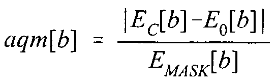
  • the masking energy level E MASK [b] is the minimum change in energy within the band b that will be perceptible to the human ear.
  • the encoder 12 at the step 56 determines whether the change in energy of a band b given by
  • the total AQM score for the whole block can be obtained at the step 56 from equation (19) by summing across all 42 critical bands according to the following equation:
  • AQM T0TAL is greater than a predetermined threshold AQM THRESH , then the corresponding block is not considered to be suitable for encoding.
  • coding of a single audio block, or even several audio blocks, whose AQM T0TAL > AQM THRESH and whose durations are each approximately 10 ms, may not result in an audible code. But if one such audio block occurs, it is likely to occur near in time to other such audio blocks with the result that, if a sufficient number of such audio blocks are grouped consecutively in a sequence, coding of one or more audio blocks in the sequence may well produce an audible code thereby degrading the quality of the original audio.
  • the encoder 12 at the step 56 maintains a count of audible blocks. If x out of y consecutive blocks prior to the current block fall in the audible code category, then the encoder 12 at the step 56 suspends coding for all subsequent blocks of the current ancillary code message. If x is equal to 9 and y is equal to 16, for example, and if 9 out 16 such audio blocks are coded in spite of the audibility scores being high, an audible code is likely to result. Therefore, in order to successfully encode a 50 bit ancillary code message, a sequence of z audio blocks is required, where the sequence of z audio blocks has less than x audible blocks in any consecutive y block segment.
  • encoding of any individual audio block may be inhibited if the AQM score for this individual audio block exceeds a threshold AQM THRESH+ which is set higher than AQM THRESH . Even though a single bit of code may be accordingly lost in such a case, the error correction discussed above will make it possible to still recover the ancillary code message.
  • Pre-echo Cancellation is a well known phenomenon that is encountered in most or all block based audio processing operations such as compression. It also occurs in the case of audio encoding as described above. Pre-echo arises when the audio energy within a block is not uniformly distributed, but is instead concentrated in the latter half of the block. Pre- echo effects are most apparent in the extreme case when the first half of the audio block has a very low level of audio and the second half of the audio block has a very high level of audio. As a result, a code signal, which is uniformly distributed across the entire audio block, has no masking energy available to make it inaudible during the first half of the audio block.
  • each audio block prior to coding at the step 56, is examined by the encoder 12 for the block's energy distribution characteristic.
  • the energy in an audio block is computed by summing the squares of the amplitudes of the time domain samples. Then, if the ratio of the energy E-, in a first part of the audio block to the energy E 2 in the remaining part of the audio block is below a threshold, a code is not inserted in the audio block.
  • the energy E-,_ and the energy E 2 are calculated according to the following equations:
  • A[s] is the amplitude of a sample s
  • S is the total number of samples in a corresponding block of audio
  • d divides the corresponding block of audio between samples in the first part of the block of audio and samples in the re- maining part of the block of audio. For example, d may divide the block of audio between samples in the first quarter of the block of audio and samples in the last three quarters of the block of audio.
  • the encoding arrangement 200 includes a delay 210 which imposes a delay on the video bit stream in order to compensate for the delay imposed on the audio bit stream by the audio encoder 206.
  • some embodiments of the encoding arrangement 200 may include a video encoder 218, which may be of known design, in order to encode the video output of the video analog to digital converter 202, or the input digital video bit stream, or the output of the demultiplexer 208, as the case may be.
  • the audio encoder 206 and/or the video encoder 218 may be adjusted so that the relative delay imposed on the audio and video bit streams is zero and so that the audio and video bit streams are thereby synchronized.
  • the delay 210 is not necessary.
  • the delay 210 may be used to provide a suitable delay and may be inserted in either the video or audio processing so that the relative delay imposed on the audio and video bit streams is zero and so that the audio and video bit streams are thereby synchronized.
  • the video encoder 218 and not the audio encoder 206 may be used.
  • the delay 210 may be required in order to impose a delay on the audio bit stream so that the relative delay between the audio and video bit streams is zero and so that the audio and video bit streams are thereby synchronized.

Abstract

Blocks of audio are encoded based upon corresponding first and second frequencies. The first and second frequencies are hopped from block to block. An audio quality measure (AQM) is computed for each block of audio such that, if x out of y blocks of audio have an AQM greater than a first predetermined threshold, encoding is suspended. For example, x may be nine and y may be 16. Also, if a ratio of the energy in a front part of a block of audio to the energy in a rear part of the block of audio is greater than a second predetermined threshold, that block of audio is not encoded even though x out of y blocks of audio have an AQM greater than the first predetermined threshold. Multiple distributors of the audio may encode the audio with their corresponding identities using the above processes.

Description

SYSTEM AND METHOD FOR ENCODING AN AUDIO SIGNAL FOR USE IN BROADCAST PROGRAM IDENTIFICATION SYSTEMS, BY ADDING INAUDIBLE CODES TO THE AUDIO SIGNAL
Related Application
This application is a continuation-in-part of U.S. Patent Application Serial No. 09/116,397 filed July 16, 1998. This application also contains disclosure similar to the disclosure in U.S. Application Serial No. (28019/35519).
Technical Field of the Invention
The present invention relates to spectral audio encoding useful, for example, in modulating broadcast signals in order to add identifying codes thereto.
Background of the Invention
Several approaches to metering the video and/or audio tuned by television and/or radio receivers in order to determine the sources or identities of corresponding televi- sion or radio programs are known. For example, one approach is to real time correlate a program to which a receiver is tuned with each of the programs available to the receiver. An apparatus useful for this measurement approach is found in the teachings of Lu et al . in U.S. Patent No. 5,594,934. Another approach is to extract a characteristic signature (or a characteristic signature set) from the program selected for viewing and/or listening, and to compare the characteristic signature (or characteristic signature set) with reference signatures (or reference signature sets) col- lected from known transmission sources at a reference site. Although the reference site could be the viewer's household, the reference site is usually at a location which is remote from the households of all of the viewers being monitored. Systems using signature extraction are taught by Lert and u in U.S. Patent No. 4,677,466 and by Kiewit and Lu in U.S. Patent No. 4,697,209.
In signature extraction systems, audio characteristic signatures are often utilized. Typically, these characteristic signatures are extracted by a unit located at the monitored receiver, sometimes referred to as a site unit. The site unit monitors the audio output of a television or radio receiver either by means of a microphone that picks up the sound from the speakers of the monitored receiver or by means of an output line from the monitored receiver. The site unit extracts and transmits the characteristic signatures to a central household unit, sometimes referred to as a home unit. Each characteristic signature is designed to uniquely characterize the audio signal tuned by the receiver during the time of signature extraction. Characteristic signatures are typically transmitted from the home unit to a central office where a matching operation is performed between the characteristic signatures and a set of reference signatures extracted at a reference site from all of the audio channels that could have been tuned by the receiver in the household being monitored. A matching score is computed by a matching algorithm and is used to determine the identity of the program to which the monitored receiver was tuned or the program source (such as a broadcaster) of the tuned program. Yet another approach to metering video and/or audio tuned by televisions and/or radios is to add ancillary identification codes to television and/or radio programs and to detect and decode the ancillary codes in order to identify the encoded programs or the corresponding program sources when the programs are tuned by monitored receivers. There are many arrangements for adding an ancillary code to a signal in such a way that the added code is not noticed. It is well known in television broadcasting, for example, to hide such ancillary codes in non-viewable portions of video by inserting them into either the video's vertical blanking interval or horizontal retrace interval . An exemplary system which hides codes in non-viewable portions of video is referred to as "AMOL" and is taught in U.S. Patent No. 4,025,851. This system is used by the assignee of this application for monitoring transmissions of television programming as well as the times of such transmissions .
Other known video encoding systems have sought to bury the ancillary code in a portion of a television signal's transmission bandwidth that otherwise carries little signal energy. An example of such a system is disclosed by Dougherty in U.S. Patent No. 5,629,739, which is assigned to the assignee of the present application.
Other methods and systems add ancillary codes to audio signals for the purpose of identifying the signals and, perhaps, for tracing their courses through signal distribution systems. Such arrangements have the obvious advantage of being applicable not only to television, but also to radio transmissions and to pre-recorded music. Moreover, ancillary codes which are added to audio signals may be reproduced in the audio signal output by a speaker. Accordingly, these arrangements offer the possibility of non- intrusively intercepting and decoding the codes with equipment that has a microphone as an input. In particular, these arrangements provide an approach to measuring program audiences by the use of portable metering equipment carried by panelists.
One such audio encoding system is disclosed by Crosby, in U.S. Patent No. 3,845,391. In this system, a code is inserted in a narrow frequency "notch" from which the original audio signal is deleted. The notch is made at a fixed predetermined frequency (e.g., 40 Hz) . This approach led to codes that were audible when the original audio signal containing the code was of low intensity.
A series of improvements followed the Crosby patent. Thus, Howard, in U.S. Patent No. 4,703,476, teaches the use of two separate notch frequencies for the mark and the space portions of a code signal. Kramer, in U.S. Patent No. 4,931,871 and in U.S. Patent No. 4,945,412 teaches, inter alia , using a code signal having an amplitude that tracks the amplitude of the audio signal to which the code is added. Program audience measurement systems in which panelists are expected to carry microphone-equipped audio monitoring devices that can pick up and store inaudible codes transmitted in an audio signal are also known. For example, Aijalla et al . , in WO 94/11989 and in U.S. Patent No. 5,579,124, describe an arrangement in which spread spectrum techniques are used to add a code to an audio signal so that the code is either not perceptible, or can be heard only as low level "static" noise. Also, Jensen et al . , in U.S. Patent No. 5,450,490, teach an arrangement for adding a code at a fixed set of frequencies and using one of two masking signals, where the choice of masking signal is made on the basis of a frequency analysis of the audio signal to which the code is to be added. Jensen et al . do not teach a coding arrangement in which the code frequencies vary from block to block. The intensity of the code inserted by Jensen et al . is a predetermined fraction of a measured value (e.g., 30 dB down from peak intensity) rather than comprising relative maxima or minima.
Moreover, Preuss et al . , in U.S. Patent No. 5,319,735, teach a multi-band audio encoding arrangement in which a spread spectrum code is inserted in recorded music at a fixed ratio to the input signal intensity (code-to-music ratio) that is preferably 19 dB . Lee et al . , in U.S. Patent No. 5,687,191, teach an audio coding arrangement suitable for use with digitized audio signals in which the code intensity is made to match the input signal by calculating a signal-to- mask ratio in each of several frequency bands and by then inserting the code at an intensity that is a predetermined ratio of the audio input in that band. As reported in this patent, Lee et al . have also described a method of embedding digital information in a digital waveform in pending U.S. application Serial No. 08/524,132.
It will be recognized that, because ancillary codes are preferably inserted at low intensities in order to prevent the code from distracting a listener of program audio, such codes may be vulnerable to various signal processing operations. For example, although Lee et al . discuss digitized audio signals, it may be noted that many of the earlier known approaches to encoding an audio signal are not compatible with current and proposed digital audio standards, particularly those employing signal compression methods that may reduce the signal's dynamic range (and thereby delete a low level code) or that otherwise may damage an ancillary code. In this regard, it is particularly important for an ancillary code to survive compression and subsequent de-compression by the AC-3 algorithm or by one of the algorithms recommended in the ISO/IEC 11172 MPEG standard, which is expected to be widely used in future digital television transmission and reception systems .
U.S. Patent Application Serial No. 09/116,397 filed July 16, 1998 discloses a system and method for inserting a code into an audio signal so that the code is likely to survive compression and decompression as required by current and proposed digital audio standards. In this system and method, spectral modulation at selected code frequencies is used to insert the code into the audio signal . These code frequencies are varied from audio block to audio block, and the spectral modulation may be implemented as amplitude modulation, modulation by frequency swapping, phase modulation, and/or odd/even index modulation. In most audio signals of the type used in television systems, a code inserted by spectral modulation in accordance with the aforementioned patent application is substantially inaudible. However, there are some instances where the code may be undesirably audible. The present invention addresses one or more of these instances. The present application also addresses methods of multi-level coding.
Summary of the Invention
According to one aspect of the present invention, a method for encoding first and second blocks of audio with corresponding first and second binary code bits comprises the following steps: a) selecting first and second frequencies from a frequency spectrum of the first block of audio; b) modulating the audio based upon the first and second frequen- cies to thereby encode the first block of audio with the first binary code bit; c) selecting third and fourth frequencies from a frequency spectrum of the second block of audio, wherein the third and fourth frequencies bear a predetermined offset relationship to the first and second frequencies; and, d) modulating the audio based upon the third and fourth frequencies to thereby encode the second block of audio with the second binary code bit .
According to another aspect of the present invention, a method for encoding a block of audio with a binary code bit comprises the following steps: a) selecting a frequency from a frequency spectrum of the block of audio; b) selectively amplifying an odd index frequency in a neighborhood of the selected frequency to be a local maximum if the block of audio is to be encoded with the binary code bit having a first value; and, c) selectively amplifying an even index frequency in a neighborhood of the selected frequency to be a local maximum if the block of audio is to be encoded with the binary code bit having a second value.
According to still another aspect of the present invention, a method for encoding blocks of audio with binary code bits comprises the following steps: a) determining an audio quality measure AQM for each block of audio; b) comparing the AQM corresponding to each block of audio to AQMTHRESH, wherein AQMTHRESH is a predetermined audio quality measure reference; c) if AQM < AQMTHRESH for x blocks of audio out of y blocks of audio, encoding the blocks of audio with binary bits, wherein x and y are corresponding predetermined numbers of blocks of audio; and, d) if AQM > AQMTHRESH for the x blocks of audio out of the y blocks of audio, suspending encoding of the blocks of audio.
According to yet another aspect of the present invention, a method is provided to encode a block of audio with a binary code bit. The block of audio has an energy. The method comprises the following steps: a) determining a ratio E1/E2, wherein E is the energy in a first portion of the block of audio, and wherein E2 is the energy in a second portion of the block of audio; b) modulating the block of audio with the binary code bit if E-L/E2 > EPRE, wherein EPRE is a predetermined reference; and, c) not modulating the block of audio with the binary code bit if E-L/E2 < EPRE .
According to a further aspect of the present invention, a method of encoding blocks of audio with binary code bits comprises the following steps: a) encoding each of the blocks of audio with a binary bit by modulating the audio within the corresponding block of audio at selected first and second frequencies, wherein the selected first and second frequencies are hopped from block to block; and, b) executing step a) so as to indicate first and second levels of distribution of the audio. According to a still further aspect of the present invention, a method for decoding first and second blocks of audio in order to recover corresponding first and second binary code bits therefrom comprises the following steps: a) detecting first and second frequencies from a frequency spec- trum of the first block of audio; b) demodulating the first and second frequencies in order to recover to the first binary code bit; c) detecting third and fourth frequencies from a frequency spectrum of the second block of audio, wherein the third and fourth frequencies bear a predetermined offset relationship to the first and second frequencies; and, d) demodulating the third and fourth frequencies in order to recover the second binary code bit .
According to yet a further aspect of the present invention, a method of decoding blocks of audio encoded with binary code bits comprises the following steps: a) decoding each of the blocks of audio in order to recover a corresponding binary bit by demodulating the audio within the corresponding block of audio at selected first and second frequencies, wherein the selected first and second frequencies are hopped from block to block; and, b) executing step a) so as identify first and second distributors of the audio.
According to another aspect of the present invention, a method of decoding a block of audio in order to re- cover a binary code bit therefrom comprises the following steps: a) detecting a frequency having an amplitude maximum within a selected frequency neighborhood of the block of audio; b) if the frequency detected in step a) corresponds to an odd frequency index, decoding the frequency as a binary code bit having a first value; and, c) if the frequency detected in step a) corresponds to an even frequency index, decoding the frequency as a binary code bit having a second value .
Brief Description of the Drawing These and other features and advantages will become more apparent from a detailed consideration of the invention when taken in conjunction with the drawings in which:
Figure 1 is a schematic block diagram of an audience measurement system employing the signal coding and decod- ing arrangements of the present invention;
Figure 2 is flow chart depicting steps performed by an encoder of the system shown in Figure 1;
Figure 3 is a spectral plot of an audio block, wherein the thin line of the plot is the spectrum of the original audio signal and the thick line of the plot is the spectrum of the signal modulated in accordance with the present invention;
Figure 4 depicts a window function which may be used to prevent transient effects that might otherwise occur at the boundaries between adjacent encoded blocks;
Figure 5 is a schematic block diagram of an arrangement for generating a seven-bit pseudo-noise synchronization sequence; Figure 6 is a spectral plot of a "triple tone" audio block which forms the first block of a preferred synchronization sequence, where the thin line of the plot is the spectrum of the original audio signal and the thick line of the plot is the spectrum of the modulated signal; Figure 7a schematically depicts an arrangement of synchronization and information blocks usable to form a complete code message;
Figure 7b schematically depicts further details of the synchronization block shown in Fig. 7a; Figure 8 is a flow chart depicting steps performed by a decoder of the system shown in Figure 1; and,
Figure 9 illustrates an encoding arrangement in which audio encoding delays are compensated in the video data stream. Detailed Description of the Invention
Audio signals are usually digitized at sampling rates that range between thirty-two kHz and forty-eight kHz. For example, a sampling rate of 44.1 kHz is commonly used during the digital recording of music. However, digital television ("DTV") is likely to use a forty eight kHz sampling rate. Besides the sampling rate, another parameter of interest in digitizing an audio signal is the number of binary bits used to represent the audio signal at each of the instants when it is sampled. This number of binary bits can vary, for example, between sixteen and twenty four bits per sample. The amplitude dynamic range resulting from using sixteen bits per sample of the audio signal is ninety-six dB. This decibel measure is the ratio between the square of the highest audio amplitude (216 = 65536) and the lowest audio amplitude (l2 = 1) . The dynamic range resulting from using twenty- four bits per sample is 144 dB . Raw audio, which is sampled at the 44.1 kHz rate and which is converted to a sixteen-bit per sample representation, results in a data rate of 705.6 kbits/s. Compression of audio signals is performed in order to reduce this data rate to a level which makes it possible to transmit a stereo pair of such data on a channel with a throughput as low as 192 kbits/s. This compression typically is accomplished by transform coding. A block consisting of Nd = 1024 samples, for example, may be decomposed, by application of a Fast Fourier Transform or other similar frequency analysis process, into a spectral representation. In order to prevent errors that may occur at the boundary between one block and the previous or subsequent block, overlapped blocks are commonly used. In one such arrangement where 1024 samples per overlapped block are used, a block includes 512 samples of "old" samples (i.e., samples from a previous block ) and 512 samples of "new" or current samples. The spectral representation of such a block is divided into critical bands where each band comprises a group of several neighboring frequencies.
The power in each of these bands can be calculated by summing the squares of the amplitudes of the frequency components within the band.
Audio compression is based on the principle of masking that, in the presence of high spectral energy at one frequency (i.e., the masking frequency), the human ear is unable to perceive a lower energy signal if the lower energy signal has a frequency (i.e., the masked frequency) near that of the higher energy signal . The lower energy signal at the masked frequency is called a masked signal. A masking threshold, which represents either (i) the acoustic energy required at the masked frequency in order to make it audible or (ii) an energy change in the existing spectral value that would be perceptible, can be dynamically computed for each band. The frequency components in a masked band can be represented in a coarse fashion by using fewer bits based on this masking threshold. That is, the masking thresholds and the amplitudes of the frequency components in each band are coded with a smaller number of bits which constitute the compressed audio. Decompression reconstructs the original signal based on this data .
Figure 1 illustrates an audience measurement system 10 in which an encoder 12 adds an ancillary code to an audio signal portion 14 of a program signal to be transmitted. Alternatively, the encoder 12 may be provided, as is known in the art, at some other location in the program signal distribution chain. A transmitter 16 transmits the encoded audio signal portion with a video signal portion 18 of the program signal. When the encoded signal is received by a receiver 20 located at a statistically selected metering site 22, the ancillary code is recovered by processing the audio signal portion of the received program signal even though the presence of that ancillary code is imperceptible to a listener when the encoded audio signal portion is supplied to speakers 24 of the receiver 20. To this end, a decoder 26 is connected either directly to an audio output 28 available at the receiver 20 or to a microphone 30 placed in the vicinity of the speakers 24 through which the audio is reproduced. The received audio signal can be either in a monaural or stereo format . ENCODING BY SPECTRAL MODULATION In order for the encoder 12 to embed a digital code in an audio data stream in a manner compatible with compression technology, the encoder 12 should preferably use frequen- cies and critical bands that match those used in compression. The block length Nc of the audio signal that is used for coding may be chosen such that, for example, 'Nc = Nd = 1024, where j is an integer. A suitable value for Nc may be, for example, 512. As depicted by a step 40 of the flow chart shown in Figure 2, which is executed by the encoder 12, a first block v(t) of Nc samples is derived from the audio signal portion 14 by the encoder 12 such as by use of an analog to digital converter, where v(t) is the time-domain representation of the audio signal within the block. An optional window may be applied to v(t) at a block 42 as discussed below in additional detail. Assuming for the moment that no such window is used, a Fourier Transform S{v(t)} of the block v(t) to be coded is computed at a step 44. (The Fourier Transform implemented at the step 44 may be a Fast Fourier Transform.)
The frequencies resulting from the Fourier Transform are indexed in the range -256 to +255, where an index of 255 corresponds to exactly half the sampling frequency fs. Therefore, for a forty-eight kHz sampling frequency, the highest index would correspond to a frequency of twenty- four kHz. Accordingly, for purposes of this indexing, the index closest to a particular frequency component f_ resulting from the Fourier Transform ${v(t)} is given by the following equation:
Figure imgf000018_0001
where equation (1) is used in the following discussion to relate a frequency f_ and its corresponding index I- .
The code frequencies f. used for coding a block may be chosen from the Fourier Transform £_{v(t)} at a step 46 in the 4.8 kHz to 6 kHz range in order to exploit the higher auditory threshold in this band. Also, each successive bit of the code may use a different pair of code frequencies f-, and f0 denoted by corresponding code frequency indexes I-, and I0. There are two preferred ways of selecting the code frequencies fj_ and f0 at the step 46 so as to create an inaudible wide-band noise like code.
(a) Direct Sequence
One way of selecting the code frequencies f1 and f0 at the step 46 is to compute the code frequencies by use of a frequency hopping algorithm employing a hop sequence Hs and a shift index ISh___- For example, if Ns bits are grouped to- gether to form a pseudo-noise sequence, Hs is an ordered sequence of Ns numbers representing the frequency deviation relative to a predetermined reference index I5k. For the case where Ns = 7 , a hop sequence Hs = {2,5,1,4,3,2,5} and a shift index Ishlft = 5, for example, could be used. In general, the indices for the Ns bits resulting from a hop sequence may be given by the following equations:
7ι = k + Hs ~ ' shift (2)
and
Figure imgf000019_0001
One possible choice for the reference frequency f5k is five kHz, for example, which corresponds to a predetermined reference index I5k = 53. This value of f5k is chosen because it is above the average maximum sensitivity frequency of the human ear. When encoding a first block of the audio signal, lλ and I0 for the first block are determined from equations (2) and (3) using a first of the hop sequence numbers; when encoding a second block of the audio signal, Ix and I0 for the second block are determined from equations (2) and (3) using a second of the hop sequence numbers; and so on. For the fifth bit in the sequence {2,5,1,4,3,2,5}, for example, the hop sequence value is three and, using equations (2) and (3), produces an index I-, = 51 and an index I0 = 61 in the case where IS _f = 5. In this example, the mid- frequency index is given by the following equation:
Figure imgf000020_0001
where Imid represents an index mid-way between the code frequency indices I-, and I0. Accordingly, each of the code frequency indices is offset from the mid-frequency index by the same magnitude, IShi_t' ^>ut the two offsets have opposite signs.
(b) Hopping based on low frequency maximum Another way of selecting the code frequencies at the step 46 is to determine a frequency index Imax at which the spectral power of the audio signal, as determined as the step 44, is a maximum in the low frequency band extending from zero Hz to two kHz. In other words, Imax is the index corresponding to the frequency having maximum power in the range of 0 - 2 kHz. It is useful to perform this calculation starting at index 1, because index 0 represents the "local" DC component and may be modified by high pass filters used in compression. The code frequency indices Iλ and I0 are chosen relative to the frequency index Imax so that they lie in a higher frequency band at which the human ear is relatively less sensitive. Again, one possible choice for the reference frequency f5k is five kHz corresponding to a reference index I5k = 53 such that Ix and I0 are given by the following equations:
Λ k + ''max ~ shift (5)
and
^0 = k + max + shift (6)
where IS _f_ is a shift index, and where Imax varies according to the spectral power of the audio signal . An important observation here is that a different set of code frequency indices I± and I0 from input block to input block is selected for spectral modulation depending on the frequency index Imax of the corresponding input block. In this case, a code bit is coded as a single bit: however, the frequencies that are used to encode each bit hop from block to block.
Unlike many traditional coding methods, such as Frequency Shift Keying (FSK) or Phase Shift Keying (PSK) , the present invention does not rely on a single fixed frequency. Accordingly, a "frequency-hopping" effect is created similar to that seen in spread spectrum modulation systems. However, unlike spread spectrum, the object of varying the coding frequencies of the present invention is to avoid the use of a constant code frequency which may render it audible.
For either of the two code frequencies selection approaches (a) and (b) described above, there are at least four modulation methods that can be implemented at a step 56 in order to encode a binary bit of data in an audio block, i.e., amplitude modulation, modulation by frequency swapping, phase modulation, and odd/even index modulation. These four methods of modulation are separately described below.
(i) Amplitude Modulation
In order to code a binary '1' using amplitude modulation, the spectral power at I1 is increased to a level such that it constitutes a maximum in its corresponding neighborhood of frequencies . The neighborhood of indices correspond- ing to this neighborhood of frequencies is analyzed at a step 48 in order to determine how much the code frequencies fx and f0 must be boosted and attenuated, respectively, so that they are detectable by the decoder 26. For index I , the neighborhood may preferably extend from l-_ - 2 to Ix + 2, and is con- strained to cover a narrow enough range of frequencies that the neighborhood of I-, does not overlap the neighborhood of l0, Simultaneously, the spectral power at I0 is modified in order to make it a minimum in its neighborhood of indices ranging from I0 - 2 to I0 + 2. Conversely, in order to code a binary '0' using amplitude modulation, the power at I0 is boosted and the power at Ix is attenuated in their corresponding neighborhoods .
As an example, Figure 3 shows a typical spectrum 50 of a Nc sample audio block plotted over a range of frequency index from forty five to seventy seven. A spectrum 52 shows the audio block after coding of a '1' bit, and a spectrum 54 shows the audio block before coding. In this particular instance of encoding a ' 1 ' bit according to code frequency selection approach (a) , the hop sequence value is five which yields a mid-frequency index of fifty eight. The values for I-L and I0 are fifty three and sixty three, respectively. The spectral amplitude at fifty three is then modified at a step 56 of Figure 2 in order to make it a maximum within its neigh- borhood of indices. The amplitude at sixty three already constitutes a minimum and, therefore, only a small additional attenuation is applied at the step 56.
The spectral power modification process requires the computation of four values each in the neighborhood of Ix and I0. For the neighborhood of Iλ these four values are as follows: (1) Imaxl which is the index of the frequency in the neighborhood of Ix having maximum power; (2) Pmaxl which is the spectral power at Imaxl; (3) Iminl which is the index of the frequency in the neighborhood of Ix having minimum power; and (4) Pminl which is the spectral power at Iminl . Corresponding values for the I0 neighborhood are Imax0, Pmax0, Iminan p ino - If Imaxl = I]_, and if the binary value to be coded is a ' 1, ' only a token increase in Pmaxl (i.e., the power at I-, ) is required at the step 56. Similarly, if Imιno = T-O' then only a token decrease in Pmax0 (i.e., the power at I0) is required at the step 56. When Pmaxl is boosted, it is multiplied by a factor 1 + A at the step 56, where A is in the range of about 1.5 to about 2.0. The choice of A is based on experimental audibility tests combined with compression survivability tests. The condition for imperceptibility requires a low value for A, whereas the condition for compression survivability requires a large value for A. A fixed value of A may not lend itself to only a token increase or decrease of power. Therefore, a more logical choice for A would be a value based on the local masking threshold. In this case, A is variable, and coding can be achieved with a minimal incremental power level change and yet survive compression.
In either case, the spectral power at Ix is given by the following equation:
pn - 0 + A)-Pmaχl (7)
with suitable modification of the real and imaginary parts of the frequency component at I-, . The real and imaginary parts are multiplied by the same factor in order to keep the phase angle constant. The power at I0 is reduced to a value corresponding to (1 + A) ~1 Pmin0 in a similar fashion.
The Fourier Transform of the block to be coded as determined at the step 44 also contains negative frequency components with indices ranging in index values from -256 to - 1. Spectral amplitudes at frequency indices -Ix and -I0 must be set to values representing the complex conjugate of amplitudes at Ix and I0, respectively, according to the following equations:
Re\A-Ix)l = ReW>)] (8)
Im[f(-I{)] = -ImWi)] (9)
Re[tl-I0)] = ReWo) (10)
Im\A-IQ)} = -ImWt)] (11)
where f(I) is the complex spectral amplitude at index I.
Compression algorithms based on the effect of masking modify the amplitude of individual spectral components by means of a bit allocation algorithm. Frequency bands sub- j ected to a high level of masking by the presence of high spectral energies in neighboring bands are assigned fewer bits, with the result that their amplitudes are coarsely quantized. However, the decompressed audio under most conditions tends to maintain relative amplitude levels at frequencies within a neighborhood. The selected frequencies in the encoded audio stream which have been amplified or attenuated at the step 56 will, therefore, maintain their relative positions even after a compression/decompression process.
It may happen that the Fourier Transform £.{v(t)} of a block may not result in a frequency component of sufficient amplitude at the frequencies £-, and f0 to permit encoding of a bit by boosting the power at the appropriate frequency. In this event, it is preferable not to encode this block and to instead encode a subsequent block where the power of the signal at the frequencies fx and f0 is appropriate for encod- ing.
(ii) Modulation by Frequency Swapping In this approach, which is a variation of the amplitude modulation approach described above in section (i) , the spectral amplitudes at Ix and Imaxl are swapped when encoding a one bit while retaining the original phase angles at I1 and
T-maxi • A similar swap between the spectral amplitudes at I0 and Imax0 is also performed. When encoding a zero bit, the roles of Ix and I0 are reversed as in the case of amplitude modulation. As in the previous case, swapping is also applied to the corresponding negative frequency indices. This encoding approach results in a lower audibility level because the encoded signal undergoes only a minor frequency distortion. Both the unencoded and encoded signals have identical energy values.
(iii) Phase Modulation The phase angle associated with a spectral component I0 is given by the following equation:
φ0 = tan" IrnW0)
(12)
R Wo)
where 0 < φ0 < 2π. The phase angle associated with I1 can be computed in a similar fashion. In order to encode a binary number, the phase angle of one of these components, usually the component with the lower spectral amplitude, can be modified to be either in phase (i.e., 0°) or out of phase (i.e., 180°) with respect to the other component, which becomes the reference. In this manner, a binary 0 may be encoded as an in-phase modification and a binary 1 encoded as an out-of- phase modification. Alternatively, a binary 1 may be encoded as an in-phase modification and a binary 0 encoded as an out- of-phase modification. The phase angle of the component that is modified is designated φM, and the phase angle of the other component is designated φR. Choosing the lower amplitude component to be the modifiable spectral component minimizes the change in the original audio signal . In order to accomplish this form of modulation, one of the spectral components may have to undergo a maximum phase change of 180°, which could make the code audible. In practice, however, it is not essential to perform phase modulation to this extent, as it is only necessary to ensure that the two components are either "close" to one another in phase or "far" apart. Therefore, at the step 48, a phase neighborhood extending over a range of ±π/4 around φR, the reference component, and another neighborhood extending over a range of ±π/4 around φR + π may be chosen. The modifiable spectral compo- nent has its phase angle φM modified at the step 56 so as to fall into one of these phase neighborhoods depending upon whether a binary '0' or a binary '1' is being encoded. If a modifiable spectral component is already in the appropriate phase neighborhood, no phase modification may be necessary. In typical audio streams, approximately 30% of the segments are "self-coded" in this manner and no modulation is required. The inverse Fourier Transform is determined at the step 62. (iv) Odd/Even Index Modulation In this odd/even index modulation approach, a single code frequency index, I1# selected as in the case of the other modulation schemes, is used. A neighborhood defined by in- dexes Ix, Iλ + 1, I1 + 2, and I± + 3, is analyzed to determine whether the index IM corresponding to the spectral component having the maximum power in this neighborhood is odd or even. If the bit to be encoded is a '1' and the index IM is odd, then the block being coded is assumed to be "auto-coded." Other- wise, an odd-indexed frequency in the neighborhood is selected for amplification in order to make it a maximum. A bit '0' is coded in a similar manner using an even index. In the neighborhood consisting of four indexes, the probability that the parity of the index of the frequency with maximum spectral power will match that required for coding the appropriate bit value is 0.25. Therefore, 25% of the blocks, on an average, would be auto-coded. This type of coding will significantly decrease code audibility.
A practical problem associated with block coding by either amplitude or phase modulation of the type described above is that large discontinuities in the audio signal can arise at a boundary between successive blocks. These sharp transitions can render the code audible. In order to eliminate these sharp transitions, the time-domain signal v(t) can be multiplied by a smooth envelope or window function w(t) at the step 42 prior to performing the Fourier Transform at the step 44. No window function is required for the modulation by frequency swapping approach described herein. The frequency distortion is usually small enough to produce only minor edge discontinuities in the time domain between adjacent blocks. The window function w(t) is depicted in Figure 4. Therefore, the analysis performed at the step 54 is limited to the central section of the block resulting from S.m{v (t ) w (t ) } . The required spectral modulation is implemented at the step 56 on the transform S{v (t) w(t) } .
The modified frequency spectrum which now contains the binary code (either '0' or '1') is subjected to an inverse transform operation at a step 62 in order to obtain the encoded time domain signal, as will be discussed below. Follow- ing the step 62, the coded time domain signal is determined at a step 64 according to the following equation:
v0( = v(t) (^(vCtMt)) v(tMt)) (13)
where the first part of the right hand side of equation (13) is the original audio signal v(t) , where the second part of the right hand side of equation (13) is the encoding, and where the left hand side of equation (13) is the resulting encoded audio signal v0(t) .
While individual bits can be coded by the method described thus far, practical decoding of digital data also requires (i) synchronization, so as to locate the start of data, and (ii) built-in error correction, so as to provide for reliable data reception. The raw bit error rate resulting from coding by spectral modulation is high and can typically reach a value of 20%. In the presence of such error rates, both synchronization and error-correction may be achieved by using pseudo-noise (PN) sequences of ones and zeroes. A PN sequence can be generated, for example, by using an m-stage shift register 58 (where m is three in the case of Figure 5) and an exclusive-OR gate 60 as shown in Figure 5. For conve- nience, an n-bit PN sequence is referred to herein as a PNn sequence. For an NPN bit PN sequence, an m-stage shift register is required operating according to the following equation:
NPN = 2m - 1 (14)
where m is an integer. With m = 3, for example, the 7-bit PN sequence (PN7) is 1110100. The particular sequence depends upon an initial setting of the shift register 58. In one robust version of the encoder 12, each individual bit of data is represented by this PN sequence - i.e., 1110100 is used for a bit '1, ' and the complement 0001011 is used for a bit ' 0. ' The use of seven bits to code each bit of code results in extremely high coding overheads.
An alternative method uses a plurality of PN15 sequences, each of which includes five bits of code data and 10 appended error correction bits. This representation provides a Hamming distance of 7 between any two 5 -bit code data words. Up to three errors in a fifteen bit sequence can be detected and corrected. This PN15 sequence is ideally suited for a channel with a raw bit error rate of 20%.
In terms of synchronization, a unique synchronization sequence 66 (Figure 7a) is required for synchronization in order to distinguish PN15 code bit sequences 74 from other bit sequences in the coded data stream. In a preferred em- bodiment shown in Figure 7b, the first code block of the synchronization sequence 66 uses a "triple tone" 70 of the synchronization sequence m which three frequencies with indices I0, I-, , and Im-d are all amplified sufficiently that each becomes a maximum in its respective neighborhood, as depicted by way of example in Figure 6. It will be noted that, although it is preferred to generate the triple tone 70 by amplifying the signals at the three selected frequencies to be relative maxima in their respective frequency neighborhoods, those signals could instead be locally attenuated so that the three associated local extreme values comprise three local minima. It should be noted that any combination of local maxima and local minima could be used for the triple tone 70. However, because program audio signals include substantial periods of silence, the preferred approach in- volves local amplification rather than local attenuation.
Being the first bit in a sequence, the hop sequence value for the block from which the triple tone 70 is derived is two and the mid- frequency index is fifty- five. In order to make the triple tone block truly unique, a shift index of seven may be chosen instead of the usual five. The three indices I0, I-, , and Imid whose amplitudes are all amplified are forty-eight, sixty-two and fifty-five as shown in Figure 6. (In this example, Imid = Hs + 53 = 2 + 53 = 55.) The triple tone 70 is the first block of the fifteen block sequence 66 and essen- tially represents one bit of synchronization data. The remaining fourteen blocks of the synchronization sequence 66 are made up of two PN7 sequences: 1110100, 0001011. This makes the fifteen synchronization blocks distinct from all the PN sequences representing code data. As stated earlier, the code data to be transmitted is converted into five bit groups, each of which is represented by a PN15 sequence. As shown in Figure 7a, an unencoded block 72 is inserted between each successive pair of PN sequences 74. During decoding, this unencoded block 72 (or gap) between neighboring PN sequences 74 allows precise syn- chronizing by permitting a search for a correlation maximum across a range of audio samples.
In the case of stereo signals, the left and right channels are encoded with identical digital data. In the case of mono signals, the left and right channels are combined to produce a single audio signal stream. Because the frequencies selected for modulation are identical in both channels, the resulting monophonic sound is also expected to have the desired spectral characteristics so that, when decoded, the same digital code is recovered.
DECODING THE SPECTRALLY MODULATED SIGNAL In most instances, the embedded digital code can be recovered from the audio signal available at the audio output 28 of the receiver 20. Alternatively, or where the receiver 20 does not have an audio output 28, an analog signal can be reproduced by means of the microphone 30 placed in the vicinity of the speakers 24. In the case where the microphone 30 is used, or in the case where the signal on the audio output 28 is analog, the decoder 20 converts the analog audio to a sampled digital output stream at a preferred sampling rate matching the sampling rate of the encoder 12. In decoding systems where there are limitations in terms of memory and computing power, a half-rate sampling could be used. In the case of half-rate sampling, each code block would consist of Nc/2 = 256 samples, and the resolution in the frequency domain (i.e., the frequency difference between successive spectral components) would remain the same as in the full sampling rate case. In the case where the receiver 20 provides digital outputs, the digital outputs are processed directly by the decoder 26 without sampling but at a data rate suitable for the decoder 26.
The task of decoding is primarily one of matching the decoded data bits with those of a PN15 sequence which could be either a synchronization sequence or a code data sequence representing one or more code data bits. The case of amplitude modulated audio blocks is considered here. However, decoding of phase modulated blocks is virtually identical, except for the spectral analysis, which would compare phase angles rather than amplitude distributions, and decoding of index modulated blocks would similarly analyze the parity of the frequency index with maximum power in the specified neighborhood. Audio blocks encoded by frequency swapping can also be decoded by the same process. In a practical implementation of audio decoding, such as may be used in a home audience metering system, the ability to decode an audio stream in real-time is highly desirable. It is also highly desirable to transmit the decoded data to a central office. The decoder 26 may be ar- ranged to run the decoding algorithm described below on Digi- tal Signal Processing (DSP) based hardware typically used in such applications. As disclosed above, the incoming encoded audio signal may be made available to the decoder 26 from either the audio output 28 or from the microphone 30 placed in the vicinity of the speakers 24. In order to increase processing speed and reduce memory requirements, the decoder 26 may sample the incoming encoded audio signal at half (24 kHz) of the normal 48 kHz sampling rate.
Before recovering the actual data bits representing code information, it is necessary to locate the synchronization sequence. In order to search for the synchronization sequence within an incoming audio stream, blocks of 256 samples, each consisting of the most recently received sample and the 255 prior samples, could be analyzed. For real-time operation, this analysis, which includes computing the Fast
Fourier Transform of the 256 sample block, has to be completed before the arrival of the next sample. Performing a 256 -point Fast Fourier Transform on a 40 MHZ DSP processor takes about 600 microseconds. However, the time between samples is only 40 microseconds, making real time processing of the incoming coded audio signal as described above impractical with current hardware .
Therefore, instead of computing a normal Fast Fourier Transform on each 256 sample block, the decoder 26 may be arranged to achieve real-time decoding by implementing an incremental or sliding Fast Fourier Transform routine 100 (Figure 8) coupled with the use of a status information array SIS that is continuously updated as processing progresses. This array comprises p elements SIS[0] to SIS[p-l] . If p = 64, for example, the elements in the status information array SIS are SIS[0] to SIS [63].
Moreover, unlike a conventional transform which computes the complete spectrum consisting of 256 frequency "bins," the decoder 26 computes the spectral amplitude only at frequency indexes that belong to the neighborhoods of interest, i.e., the neighborhoods used by the encoder 12. In a typical example, frequency indexes ranging from 45 to 70 are adequate so that the corresponding frequency spectrum contains only twenty-six frequency bins. Any code that is recovered appears in one or more elements of the status information array SIS as soon as the end of a message block is encountered.
Additionally, it is noted that the frequency spectrum as analyzed by a Fast Fourier Transform typically changes very little over a small number of samples of an audio stream. Therefore, instead of processing each block of 256 samples consisting of one "new" sample and 255 "old" samples, 256 sample blocks may be processed such that, in each block of 256 samples to be processed, the last k samples are "new" and the remaining 256-k samples are from a previous analysis. In the case where k = 4 , processing speed may be increased by skipping through the audio stream in four sample increments, where a skip factor k is defined as k - 4 to account for this operation. Each element SIS [p] of the status information array
SIS consists of five members: a previous condition status PCS, a next jump index JI , a group counter GC, a raw data array DA, and an output data array OP. The raw data array DA has the capacity to hold fifteen integers. The output data array OP stores ten integers, with each integer of the output data array OP corresponding to a five bit number extracted from a recovered PN15 sequence. This PN15 sequence, accordingly, has five actual data bits and ten other bits. These other bits may be used, for example, for error correction. It is assumed here that the useful data in a message block consists of 50 bits divided into 10 groups with each group containing 5 bits, although a message block of any size may be used.
The operation of the status information array SIS is best explained in connection with Figure 8. An initial block of 256 samples of received audio is read into a buffer at a processing stage 102. The initial block of 256 samples is analyzed at a processing stage 104 by a conventional Fast Fourier Transform to obtain its spectral power distribution. All subsequent transforms implemented by the routine 100 use the high-speed incremental approach referred to above and described below.
In order to first locate the synchronization sequence, the Fast Fourier Transform corresponding to the ini- tial 256 sample block read at the processing stage 102 is tested at a processing stage 106 for a triple tone, which represents the first bit in the synchronization sequence. The presence of a triple tone may be determined by examining the initial 256 sample block for the indices I0, Ix, and Imid used by the encoder 12 in generating the triple tone, as described above. The SIS [p] element of the SIS array that is associated with this initial block of 256 samples is SIS[0], where the status array index p is equal to 0. If a triple tone is found at the processing stage 106, the values of certain members of the SIS[0] element of the status information array SIS are changed at a processing stage 108 as follows: the previous condition status PCS, which is initially set to 0, is changed to a 1 indicating that a triple tone was found in the sample block corresponding to SIS[0]; the value of the next jump index JI is incremented to 1; and, the first integer of the raw data member DA[0] in the raw data array DA is set to the value (0 or 1) of the triple tone. In this case, the first integer of the raw data member DA[0] in the raw data array DA is set to 1 because it is assumed in this analysis that the triple tone is the equivalent of a 1 bit. Also, the status array index p is incremented by one for the next sample block. If there is no triple tone, none of these changes in the SIS [0] element are made at the processing stage 108, but the status array index p is still incremented by one for the next sample block. Whether or not a triple tone is detected in this 256 sample block, the routine 100 enters an incremental FFT mode at a processing stage 110.
Accordingly, a new 256 sample block increment is read into the buffer at a processing stage 112 by adding four new samples to, and discarding the four oldest samples from, the initial 256 sample block processed at the processing stages 102 - 106. This new 256 sample block increment is analyzed at a processing stage 114 according to the following steps :
STEP 1 : the skip factor k of the Fourier Transform is applied according to the following equation in order to modify each frequency component Fold(u0) of the spectrum corresponding to the initial sample block in order to derive a corresponding intermediate frequency component Fλ (u0) :
2πuQk
(15) where u0 is the frequency index of interest. In accordance with the typical example described above, the frequency index u0 varies from 45 to 70. It should be noted that this first step involves multiplication of two complex numbers.
STEP 2 : the effect of the first four samples of the old 256 sample block is then eliminated from each Fx (u0) of the spectrum corresponding to the initial sample block and the effect of the four new samples is included in each Fx(u0) of the spectrum corresponding to the current sample block increment in order to obtain the new spectral amplitude Fnew(u0) for each frequency index u0 according to the following equation:
^ 2πu k-m + \)
FneM - F o) + Σ ( » - /»)exp-( 5—; ) (16) m = \ 256
where fold and fnew are the time-domain sample values. It should be noted that this second step involves the addition of a complex number to the summation of a product of a real number and a complex number. This computation is repeated across the frequency index range of interest (for example, 45 to 70) . STEP 3 : the effect of the multiplication of the 256 sample block by the window function in the encoder 12 is then taken into account. That is, the results of step 2 above are not confined by the window function that is used in the encoder 12. Therefore, the results of step 2 preferably should be multiplied by this window function. Because multiplication in the time domain is equivalent to a convolution of the spectrum by the Fourier Transform of the window function, the results from the second step may be convolved with the window func- tion. In this case, the preferred window function for this operation is the following well known "raised cosine" function which has a narrow 3 -index spectrum with amplitudes (-0.50, 1, +0.50) :
Figure imgf000042_0001
where Tw is the width of the window in the time domain. This "raised cosine" function requires only three multiplication and addition operations involving the real and imaginary parts of the spectral amplitude. This operation significantly improves computational speed. This step is not required for the case of modulation by frequency swapping. STEP 4 : the spectrum resulting from step 3 is then examined for the presence of a triple tone. If a triple tone is found, the values of certain members of the SIS [1] element of the status information array SIS are set at a processing stage 116 as follows: the previous condition status PCS, which is initially set to 0, is changed to a 1; the value of the next jump index JI is incremented to 1; and, the first integer of the raw data member DA[1] in the raw data array DA is set to 1. Also, the status array index p is incremented by One . If there is no triple tone, none of these changes are made to the members of the structure of the SIS [1] element at the processing stage 116, but the status array index p is still incremented by one .
Because p is not yet equal to 64 as determined at a processing stage 118 and the group counter GC has not accumulated a count of 10 as determined at a processing stage 120, this analysis corresponding to the processing stages 112 - 120 proceeds in the manner described above in four sample increments where p is incremented for each sample increment . When SIS [63] is reached where p = 64, p is reset to 0 at the processing stage 118 and the 256 sample block increment now in the buffer is exactly 256 samples away from the location in the audio stream at which the SIS [0] element was last updated. Each time p reaches 64, the SIS array represented by the SIS [0] - SIS [63] elements is examined to determine whether the previous condition status PCS of any of these elements is one indicating a triple tone. If the previous condition status PCS of any of these elements corresponding to the current 64 sample block increments is not one, the processing stages 112 - 120 are repeated for the next 64 block increments. (Each block increment comprises 256 samples.)
Once the previous condition status PCS is equal to 1 for any of the SIS [0] - SIS [63] elements corresponding to any set of 64 sample block increments, and the corresponding raw data member D [p] is set to the value of the triple tone bit, the next 64 block increments are analyzed at the processing stages 112 - 120 for the next bit in the synchronization sequence .
Each of the new block increments beginning where p was reset to 0 is analyzed for the next bit in the synchronization sequence. This analysis uses the second member of the hop sequence Hs because the next jump index JI is equal to 1. From this hop sequence number and the shift index used in encoding, the Ix and I0 indexes can be determined, for example from equations (2) and (3) . Then, the neighborhoods of the I-_ and I0 indexes are analyzed to locate maximums and minimums in the case of amplitude modulation. If, for example, a power maximum at Ix and a power minimum at I0 are detected, the next bit in the synchronization sequence is taken to be 1. In order to allow for some variations in the signal that may arise due to compression or other forms of distortion, the index for either the maximum power or minimum power in a neighborhood is allowed to deviate by 1 from its expected value. For example, if a power maximum is found in the index Il r and if the power minimum in the index I0 neighborhood is found at I0 - 1, instead of I0, the next bit in the synchronization sequence is still taken to be 1. On the other hand, if a power minimum at Ix and a power maximum at I0 are detected using the same allowable variations discussed above, the next bit in the synchronization sequence is taken to be 0. However, if none of these conditions are satisfied, the output code is set to -1, indicating a sample block that cannot be decoded. Assuming that a 0 bit or a 1 bit is found, the second integer of the raw data member DA[1] in the raw data array DA is set to the appropriate value, and the next jump index JI of SIS [0] is incremented to 2, which corresponds to the third member of the hop sequence Hs . From this hop sequence number and the shift index used in encoding, the I± and I0 indexes can be determined. Then, the neighborhoods of the Ix and I0 indexes are analyzed to locate maximums and minimums in the case of amplitude modulation so that the value of the next bit can be decoded from the third set of 64 block increments, and so on for fifteen such bits of the synchronization sequence. The fifteen bits stored in the raw data array DA may then be compared with a reference synchronization sequence to determine synchronization. If the number of errors between the fifteen bits stored in the raw data array DA and the reference synchronization sequence exceeds a previously set threshold, the extracted sequence is not acceptable as a synchronization, and the search for the synchronization sequence begins anew with a search for a triple tone.
If a valid synchronization sequence is thus detected, there is a valid synchronization, and the PN15 data sequences may then be extracted using the same analysis as is used for the synchronization sequence, except that detection of each PN15 data sequence is not conditioned upon detection of the triple tone which is reserved for the synchronization sequence. As each bit of a PN15 data sequence is found, it is inserted as a corresponding integer of the raw data array DA. When all integers of the raw data array DA are filled, (i) these integers are compared to each of the thirty-two possible PN15 sequences, (ii) the best matching sequence indicates which 5 -bit number to select for writing into the appropriate array location of the output data array OP, and (iii) the group counter GC member is incremented to indicate that the first PN15 data sequence has been successfully extracted. If the group counter GC has not yet been incremented to 10 as determined at the processing stage 120, program flow returns to the processing stage 112 in order to decode the next PN15 data sequence. When the group counter GC has incremented to 10 as determined at the processing stage 120, the output data array OP, which contains a full 50-bit message, is read at a processing stage 122. The total number of samples in a message block is 45,056 at a half-rate sampling frequency of 24 kHz. It is possible that several adjacent elements of the status information array SIS, each representing a message block separated by four samples from its neighbor, may lead to the recovery of the same message because synchronization may occur at several locations in the audio stream which are close to one another. If all these messages are identical, there is a high probability that an error- free code has been received.
Once a message has been recovered and the message has been read at the processing stage 122, the previous condi- tion status PCS of the corresponding SIS element is set to 0 at a processing stage 124 so that searching is resumed at a processing stage 126 for the triple tone of the synchronization sequence of the next message block.
MULTI -LEVEL CODING Often there is a need to insert more than one code message into the same audio stream. For example in a television program distribution environment, the network originator of the program may insert its identification code and time stamp, and a network affiliated station carrying this program may also insert its own identification code. In addition, an advertiser or sponsor may wish to have its code added. It is noted that the network originator, the network affiliated station, and the advertiser are at different distribution levels between audio origination and audio reception by the consumer. There are a number of methods of accommodating multi-level encoding in order to designate more than one distributor of the audio.
(i) Bit Reservation In order to accommodate multi-level coding, 48 bits in a 50 -bit system can be used for the code and the remaining 2 bits can be used for level specification. Usually the first program material generator, say the network, will insert codes in the audio stream. Its first message block would have the level bits set to 00, and only a synchronization sequence and the 2 level bits are set for the second and third message blocks in the case of a three level system. For example, the level bits for the second and third messages may be both set to 11 indicating that the actual data areas have been left unused.
The network affiliated station can now enter its code with a decoder/encoder combination that would locate the synchronization of the second message block with the 11 level setting. This station inserts its code in the data area of this block and sets the level bits to 01. The next level encoder inserts its code in the third message block's data area and sets the level bits to 10. During decoding, the level bits distinguish each message level category.
(ii) Frequency Multiplexing
In frequency multiplexing, each code level (e.g., network, affiliate, advertiser) is assigned to a different frequency band in the spectrum. In determining the size of a frequency band and, therefore, the number of bands that may be coded, it is noted that each code level generally requires a minimum of eighteen consecutive spectral lines when using the coding methods described herein. This requirement follows from the way in which a triple tone is coded. That is, in coding a triple tone, the frequencies corresponding to indices I1# I0, and Imid are all amplified. Because Ix = forty-eight and I0 = sixty-two, the two outer frequencies corresponding to Ix and I0 are separated by fourteen spectral lines. In addition, the neighborhoods defined for these frequencies extend two spectral lines on either side of these two frequencies for a total of eighteen spectral lines.
At a sampling rate of 48 kHz and 512 samples per block, eighteen spectral lines correspond to a spectral width of 1.69 kHz. In order to insert a code, there must be enough energy within this 1.69 kHz band to provide masking for the code signal . Three levels of code can be inserted in an audio signal typically having a bandwidth of 8 kHz by choosing the following bands: 2.9 kHz to 4.6 kHz for a first level of coding; 4.6 kHz to 6.3 kHz for a second level of coding; and, 6.3 kHz to 8.0 kHz for a third level of coding. However, it should be noted that audio consisting of speech usually has a bandwidth lower than 5 kHz and may, therefore, support only a single level of code.
(iii) Primary/Secondary Encoding In this method of encoding, two types of encoders, a primary encoder and one or more secondary encoders, may be used to insert different levels of code. The various levels of code can be arranged hierarchically in such a manner that the primary encoder inserts at least the synchronization sequence and may also insert one of the levels, such as the highest level, of code. During encoding, and preferably prior to insertion of the synchronization sequence, the primary encoder leaves a predetermined number of audio blocks uncoded to permit the secondary encoders to insert their assigned levels of code. Accordingly, the secondary encoders have the capability to both decode and encode audio such that they first locate the synchronization sequence inserted by the primary encoder, and then determine their assigned positions in the audio stream for insertion of their corresponding codes. In the decoding process, the synchronization sequence is first detected, and then the several levels of codes are recovered sequentially.
CODE ERASURE AND OVERWRITE It may also be necessary to provide a means of erasing a code or to erase and overwrite a code. Erasure may be accomplished by detecting the triple tone/synchronization sequence using a decoder and by then modifying at least one of the triple tone frequencies such that the code is no longer recoverable. Overwriting involves extracting the synchronization sequence in the audio, testing the data bits in the data area and inserting a new bit only in those blocks that do not have the desired bit value. The new bit is inserted by amplifying and attenuating appropriate frequencies in the data area.
DELAY COMPENSATION In a practical implementation of the encoder 12, Nc samples of audio, where Nc is typically 512, are processed at any given time. In order to achieve operation with a minimum amount of throughput delay, the following four buffers are used: input buffers INO and INI, and output buffers OUT0 and OUT1. Each of these buffers can hold Nc samples. While samples in the input buffer INO are being processed, the input buffer INI receives new incoming samples. The processed output samples from the input buffer INO are written into the output buffer OUTO, and samples previously encoded are written to the output from the output buffer OUT1. When the operation associated with each of these buffers is completed, processing begins on the samples stored in the input buffer INI while the input buffer INO starts receiving new data. Data from the output buffer OUTO are now written to the output. This cycle of switching between the pair of buffers in the input and output sections of the encoder continues as long as new audio samples arrive for encoding. It is clear that a sample arriving at the input suffers a delay equivalent to the time duration required to fill two buffers at the sampling rate of 48 kHz before its encoded version appears at the output . This delay is approximately 22 ms . When the encoder 12 is used in a television system environment, it is necessary to compensate for this delay in order to maintain synchronization between video and audio.
Such a compensation arrangement is shown in Figure 9. As shown in Figure 9, an encoding arrangement 200, which may be used for the elements 12, 14, and 18 in Figure 1, is arranged to receive either analog video and audio inputs or digital video and audio inputs. Analog video and audio inputs are supplied to corresponding video and audio analog to digi- tal converters 202 and 204. The audio samples from the audio analog to digital converter 204 are provided to an audio encoder 206 which may be of known design or which may be arranged as disclosed above. The digital audio input is supplied directly to the audio encoder 206. Alternatively, if the input digital bit stream is a combination of digital video and audio bit stream portions, the input digital bit stream is provided to a demultiplexer 208 which separates the digital video and audio portions of the input digital bit stream and supplies the separated digital audio portion to the audio encoder 206.
Because the audio encoder 206 imposes a delay on the digital audio bit stream as discussed above relative to the digital video bit stream, a delay 210 is introduced in the digital video bit stream. The delay imposed on the digital video bit stream by the delay 210 is equal to the delay imposed on the digital audio bit stream by the audio encoder 206. Accordingly, the digital video and audio bit streams downstream of the encoding arrangement 200 will be synchronized. In the case where analog video and audio inputs are provided to the encoding arrangement 200, the output of the delay 210 is provided to a video digital to analog converter 212 and the output of the audio encoder 206 is provided to an audio digital to analog converter 214. In the case where separate digital video and audio bit streams are provided to the encoding arrangement 200, the output of the delay 210 is provided directly as a digital video output of the encoding arrangement 200 and the output of the audio encoder 206 is provided directly as a digital audio output of the encoding arrangement 200. However, in the case where a combined digital video and audio bit stream is provided to the encoding arrangement 200, the outputs of the delay 210 and of the audio encoder 206 are provided to a multiplexer 216 which recombines the digital video and audio bit streams as an output of the encoding arrangement 200.
As explained above, there may be some instances where the arrangement described above can result in undesirable audibility of the ancillary code inserted into a program audio signal . Two such instances and exemplary solutions to these two instances are described below.
Controlling Code Audibility Using an Audio Quality Measure (AQM)
One example of audio material that is difficult to inaudibly encode is instrumental music characterized by strong harmonics or by a strong fundamental frequency in the code frequency band. Shifting the frequency maxima and minima in such cases can lead to audible distortion. Therefore, an audibility score, which is designated herein as the audio quality measure (AQM) , can be computed in order to determine when instances of potentially audible code segments occur. AQM computation may be based on psycho-acoustic models that are widely used in audio compression algorithms such as Dolby's AC-3, MPEG-2 Layers I, II, or III, or MPEG- AAC. The AQM computation discussed below is based on MPEG- AAC . However, the AQM computation may be based any of these audio compression algorithms. (For example, in the Dolby AC-3 audio compression method, a Modified Discrete Cosine Transform (MDCT) spectrum is used for computing the masking levels.)
Let it be assumed that blocks of 512 samples at a 48 kHz sampling rate are used to compute the AQM. The frequency space extending from 0 to 24 kHz is divided into 42 critical bands. Prior to encoding a block of audio as described above, the spectral energy E0 [b] in each critical band, where b is the band index, is computed by the encoder 12 at the step 48 in accordance with the following equation:
f=β
(18) f=β
where A[f] is the amplitude at a frequency component f in the corresponding critical band of the audio block, fi is the initial frequency component in the corresponding critical band of the audio block, and fl is the last frequency component in the corresponding critical band of the audio block. A masking energy level
Figure imgf000056_0001
is also computed at the step 48 following the methodology described in ISO/IEC 13818-7:1997. The masking energy level EMASK[b] is the minimum change in energy within the band b that will be perceptible to the human ear.
If this block were to be coded by the spectral modulation procedure described earlier in this application, a new energy level value Ec [b] for each band in the coded block will result and can be computed at the step 48 using equation (18) .
The encoder 12 at the step 56 determines whether the change in energy of a band b given by |Ec[b] - E0 [b] | is less than the masking energy level E^^th] . If |Ec[b] - E0 [b] | is less than EMASK[b], it can be assumed that there is adequate masking energy available in the band b to make the change resulting from coding imperceptible. Therefore, an aqm[b] for this band b is assumed to be zero. However, if |Ec[b] - E0 [b] | > EMASK [b] for the band b, the aqm for the band can be computed at the step 56 as follows:
Figure imgf000056_0002
The total AQM score for the whole block can be obtained at the step 56 from equation (19) by summing across all 42 critical bands according to the following equation:
6=41 AQMT0TAL = ∑ aqm[b] (20) b=0
If it is determined at the step 56 that AQMT0TAL is greater than a predetermined threshold AQMTHRESH, then the corresponding block is not considered to be suitable for encoding.
In practice, however, coding of a single audio block, or even several audio blocks, whose AQMT0TAL > AQMTHRESH and whose durations are each approximately 10 ms, may not result in an audible code. But if one such audio block occurs, it is likely to occur near in time to other such audio blocks with the result that, if a sufficient number of such audio blocks are grouped consecutively in a sequence, coding of one or more audio blocks in the sequence may well produce an audible code thereby degrading the quality of the original audio.
Therefore, in order to determine when to encode and when to suspend encoding, the encoder 12 at the step 56 maintains a count of audible blocks. If x out of y consecutive blocks prior to the current block fall in the audible code category, then the encoder 12 at the step 56 suspends coding for all subsequent blocks of the current ancillary code message. If x is equal to 9 and y is equal to 16, for example, and if 9 out 16 such audio blocks are coded in spite of the audibility scores being high, an audible code is likely to result. Therefore, in order to successfully encode a 50 bit ancillary code message, a sequence of z audio blocks is required, where the sequence of z audio blocks has less than x audible blocks in any consecutive y block segment. In addition, encoding of any individual audio block may be inhibited if the AQM score for this individual audio block exceeds a threshold AQMTHRESH+ which is set higher than AQMTHRESH. Even though a single bit of code may be accordingly lost in such a case, the error correction discussed above will make it possible to still recover the ancillary code message.
Pre-echo Cancellation Pre-echo is a well known phenomenon that is encountered in most or all block based audio processing operations such as compression. It also occurs in the case of audio encoding as described above. Pre-echo arises when the audio energy within a block is not uniformly distributed, but is instead concentrated in the latter half of the block. Pre- echo effects are most apparent in the extreme case when the first half of the audio block has a very low level of audio and the second half of the audio block has a very high level of audio. As a result, a code signal, which is uniformly distributed across the entire audio block, has no masking energy available to make it inaudible during the first half of the audio block.
Therefore, each audio block, prior to coding at the step 56, is examined by the encoder 12 for the block's energy distribution characteristic. The energy in an audio block is computed by summing the squares of the amplitudes of the time domain samples. Then, if the ratio of the energy E-, in a first part of the audio block to the energy E2 in the remaining part of the audio block is below a threshold, a code is not inserted in the audio block. The energy E-,_ and the energy E2 are calculated according to the following equations:
s-d ∑ A 2[s] (21) s=o
and
s=S
E2 = ∑ A 2[s] (22) s=d+l where A[s] is the amplitude of a sample s, S is the total number of samples in a corresponding block of audio, and d divides the corresponding block of audio between samples in the first part of the block of audio and samples in the re- maining part of the block of audio. For example, d may divide the block of audio between samples in the first quarter of the block of audio and samples in the last three quarters of the block of audio.
Certain modifications of the present invention have been discussed above. Other modifications will occur to those practicing in the art of the present invention. For example, according to the description above, the encoding arrangement 200 includes a delay 210 which imposes a delay on the video bit stream in order to compensate for the delay imposed on the audio bit stream by the audio encoder 206. However, some embodiments of the encoding arrangement 200 may include a video encoder 218, which may be of known design, in order to encode the video output of the video analog to digital converter 202, or the input digital video bit stream, or the output of the demultiplexer 208, as the case may be. When the video encoder 218 is used, the audio encoder 206 and/or the video encoder 218 may be adjusted so that the relative delay imposed on the audio and video bit streams is zero and so that the audio and video bit streams are thereby synchronized. In this case, the delay 210 is not necessary. Alternatively, the delay 210 may be used to provide a suitable delay and may be inserted in either the video or audio processing so that the relative delay imposed on the audio and video bit streams is zero and so that the audio and video bit streams are thereby synchronized.
In still other embodiments of the encoding arrangement 200, the video encoder 218 and not the audio encoder 206 may be used. In this case, the delay 210 may be required in order to impose a delay on the audio bit stream so that the relative delay between the audio and video bit streams is zero and so that the audio and video bit streams are thereby synchronized.
Accordingly, the description of the present invention is to be construed as illustrative only and is for the purpose of teaching those skilled in the art the best mode of carrying out the invention. The details may be varied substantially without departing from the spirit of the invention, and the exclusive use of all modifications which are within the scope of the appended claims is reserved.

Claims

WHAT IS CLAIMED IS:
1. A method for encoding first and second blocks of audio with corresponding first and second binary code bits comprising the following steps: a) selecting first and second frequencies from a frequency spectrum of the first block of audio; b) modulating the audio based upon the first and second frequencies to thereby encode the first block of audio with the first binary code bit; c) selecting third and fourth frequencies from a frequency spectrum of the second block of audio, wherein the third and fourth frequencies bear a predetermined offset relationship to the first and second frequencies; and, d) modulating the audio based upon the third and fourth frequencies to thereby encode the second block of audio with the second binary code bit.
2. The method of claim 1 wherein: step b) comprises the steps of (i) increasing the spectral power at one of the first and second frequencies so as to render the spectral power at the one of the first and second frequencies a local maximum, and (ii) decreasing the spectral power at the other of the first and second frequen- cies so as to render the spectral power at the other of the first and second frequencies a local minimum; and, step d) comprises the steps of (i) increasing the spectral power at one of the third and fourth frequencies so as to render the spectral power at the one of the third and fourth frequencies a local maximum, and (ii) decreasing the spectral power at the other of the third and fourth frequen- cies so as to render the spectral power at the other of the third and fourth frequencies a local minimum.
3. The method of claim 1 wherein: step b) comprises the step of selectively changing a phase relationship between the first and second frequencies; and, step d) comprises the step of selectively changing a phase relationship between the third and fourth frequencies.
4. The method of claim 1 wherein: step b) comprises the step of swapping a spectral amplitude of at least one of the first and second frequencies with a spectral amplitude of a frequency having a maximum amplitude in a frequency neighborhood of the least one of the first and second frequencies; and, step d) comprises the step of swapping a spectral amplitude of at least one of the third and fourth frequencies with a spectral amplitude of a frequency having a maximum amplitude in a frequency neighborhood of the at least one of the third and fourth frequencies.
5. The method of claim 1 wherein the predetermined offset relationship is determined by a frequency hop sequence.
6. The method of claim 1 wherein the predetermined offset relationship is determined by hopping based on a low frequency maximum.
7. The method of claim 1 wherein the first and second frequencies are selected according to a reference frequency, a frequency hop sequence, and a predetermined shift index, and wherein the third and fourth frequencies are se- lected according to the reference frequency, the frequency hop sequence, and the predetermined shift index.
8. The method of claim 7 wherein the first and second frequencies are selected according to the following equations:
'5*, + Ho shift
and 4> = '5* H. + I shift
wherein Ix and I0 are indexes corresponding to the first and second frequencies respectively, wherein I5k is an index corre- sponding to the reference frequency, wherein Ηs is a component of the frequency hop sequence, and wherein Ishift is the prede- termined shift index.
9. The method of claim 1 wherein the first and second frequencies are selected according to a reference frequency, a first low frequency maximum, and a predetermined shift index, and wherein the third and fourth frequencies are selected according to the reference frequency, a second low frequency maximum, and the predetermined shift index.
10. The method of claim 9 wherein the first and second frequencies are selected according to the following equations :
L 1 = 5k. + I max - / sh,if.,t,
and
A) hk + ''max + * shift wherein Ix and I0 are indexes corresponding to the first and second frequencies respectively, wherein I5k is an index corre- spond g to the reference frequency, wherein Imax is an index corresponding to a frequency at which the spectral power of the first block of audio is a maximum in a low frequency band of the first block of audio, and wherein IS ιfe 1S the predeter- mined shift index.
11. The method of claim 1 wherein a synchronization block is added to the signal, and wherein the synchronization block is characterized by a triple tone portion.
12. The method of claim 1 further comprising the following steps: e) determining an audio quality measure AQM for the first block of audio; f) comparing AQM to AQMTHRESH, wherein AQMTHRESH is a predetermined threshold audio quality measure reference; and, g) if AQM > AQMTHRESH, inhibiting step b) .
13. The method of claim 12 wherein the first block of audio has a spectral energy, wherein
Figure imgf000066_0001
wherein the first block of audio is divided into B frequency bands, wherein b is a variable representing a frequency band within the B frequency bands, wherein E0 [b] is the spectral energy in the first block of audio without coding, wherein Ec [b] is the spectral energy in the first block of audio with coding, and wherein
b=B
AQM = ∑ aqm[b] .
6=0
14. The method of claim 1 further comprising the following steps: e) determining an audio quality measure AQM for each of a plurality of blocks of audio; f) comparing the AQM corresponding to each of the plurality of blocks of audio to AQMTHRESH, wherein AQMTHRESH is a predetermined threshold audio quality measure reference; and, g) if AQM > AQMTHRESH for x blocks of audio out of y blocks of audio of the plurality of blocks of audio, encoding of the audio with binary bits is suspended, wherein x and y are corresponding predetermined numbers of blocks of audio.
15. The method of claim 14 wherein y is a predeter- mined number of consecutive blocks of audio.
16. The method of claim 14 wherein encoding of any single block of audio is inhibited if AQM > AQMTHRESH+ for that block of audio, and wherein AQMTHRESH+ > AQMTHRESH.
17. The method of claim 14 wherein each of the y blocks of audio has a spectral energy, wherein
\Ec[b] -E0[b] \ aqm[b =
JMASK [\ b]
wherein each of the y blocks of audio is divided into B fre- quency bands, wherein b is a variable representing a frequency band within the B frequency bands, wherein E0 [b] is the spec- tral energy in a frequency band b of each of the blocks of audio without coding, wherein Ec [b] is the spectral energy in the frequency band b of each of the blocks of audio with coding, and wherein
b=B
AQM = ∑ aqm[b] . b=0
18. The method of claim 1 wherein the first block of audio has energy, wherein step b) is inhibited if Ex/E2 < EPRE, wherein Ex is the energy in a first portion of the first block of audio, wherein E2 is the energy in a second portion of the first block of audio, and wherein EPRE is a predeter- mined reference.
19. The method of claim 18 wherein Ex represents the energy in a first quarter of the first block of audio and E2 represents the energy in a last three quarters of the first block of audio.
20. The method of claim 18 wherein the first block of audio is sampled to produce S samples, wherein Ex is deter- mined according to the following equation:
s=cl
E, = ∑ A 2[s] s=0
wherein Ε2 is determined according to the following equation:
s=S = Σ A 2[s] s =d+ \
wherein A[s] is the amplitude A of a sample s in the first block of audio, and wherein d is chosen so as the divide E-, from E2.
21. The method of claim 20 wherein d is chosen so that Ex represents the energy in a first quarter of the first block of audio and so that E2 represents the energy in a last three quarters of the first block of audio.
22. The method of claim 1 further comprising the step of encoding 1 blocks of audio with binary code bits, wherein n of the binary code bits are arranged to designate a distribution level of encoding.
23. The method of claim 22 wherein k groups of 1 blocks of audio in an audio stream are set aside for encoding by k distributors of the audio, and wherein a predetermined combination of the n binary code bits of a corresponding group of 1 blocks of audio is arranged to indicate that the corre- sponding group of 1 blocks of audio has not been encoded by a distributor.
24. The method of claim 1 further comprising the step of encoding more than one frequency band within the first and second blocks of audio with corresponding binary code bits, wherein each frequency band is encoded by a different distributor of the audio.
25. The method of claim 1 further comprising the following steps: e) encoding, by use of a primary encoder, a group of blocks of audio with a synchronization sequence, wherein the primary encoder leaves a predetermined number of groups of additional blocks of audio uncoded; and, f) encoding, by use of either the primary encoder or a secondary encoder, a first corresponding one of the groups of blocks of additional audio so as to identify a first distributor of the audio; and, g) encoding, by use of a secondary encoder, a second corresponding one of the groups of additional blocks of audio so as to identify a second distributor of the audio.
26. A method for encoding a block of audio with a binary code bit comprising the following steps: a) selecting a frequency from a frequency spectrum of the block of audio; b) selectively amplifying an odd index frequency in a neighborhood of the selected frequency to be a local maximum if the block of audio is to be encoded with the binary code bit having a first value; and, c) selectively amplifying an even index frequency in a neighborhood of the selected frequency to be a local maximum if the block of audio is to be encoded with the binary code bit having a second value.
27. The method of claim 26 wherein the block of audio is a first block of audio, wherein the binary code bit is a first binary code bit, wherein the frequency selected in step a) is a first frequency, and wherein the method further comprises the following steps: d) selecting a second frequency from a frequency spectrum of a second block of audio, wherein the second fre- quency bears a predetermined offset relationship to the first frequency; e) selectively amplifying an odd index frequency in a neighborhood of the second frequency to be a local maximum if the second block of audio is to be encoded with a second binary code bit having one of the first and second values; and, f) selectively amplifying an even index frequency in a neighborhood of the second frequency to be a local maxi- mum if the second block of audio is to be encoded with the second binary code bit having the other of the first and second values.
28. A method for encoding blocks of audio with binary code bits comprising the following steps: a) determining an audio quality measure AQM for each block of audio; b) comparing the AQM corresponding to each block of audio to AQMTHRESH, wherein AQMTHRESH is a predetermined audio quality measure reference; c) if AQM < AQMTHRESH for x blocks of audio out of y blocks of audio, encoding the blocks of audio with binary bits, wherein x and y are corresponding predetermined numbers of blocks of audio; and, d) if AQM > AQMTHRESH for the x blocks of audio out of the y blocks of audio, suspending encoding of the blocks of audio.
29. The method of claim 28 wherein y is a predeter- mined number of consecutive blocks of audio.
30. The method of claim 28 wherein encoding of any single block of audio is inhibited if AQM > AQMTHRESH+ for that block of audio, and wherein AQMTHRESH+ > AQMTHRESH.
31. The method of claim 28 wherein each of the blocks of audio has a spectral energy, wherein \Ec[b] -EQ[b] \ aqm[b -
'MASK1 [b]
wherein each of the blocks of audio is divided into B fre- quency bands, wherein b is a variable representing a frequency band within the B frequency bands, wherein E0 [b] is the spec- tral energy in a frequency band b of each of the blocks of audio without coding, wherein Ec [b] is the spectral energy in the frequency band b of each of the blocks of audio with coding, and wherein
_>=_?
AQM = ∑ aqm[b\ . b=0
32. The method of claim 31 wherein y is a predeter- mined number of consecutive blocks of audio.
33. The method of claim 28 wherein step c) com- prises the steps of increasing the spectral power at one of first and second frequencies within a corresponding block of audio so as to render the spectral power at the one of the first and second frequencies a local maximum, and decreasing the spectral power at the other of the first and second fre- quencies so as to render the spectral power at the other of the first and second frequencies a local minimum.
34. The method of claim 28 wherein step c) com- prises the step of selectively changing a phase relationship between first and second frequencies, and wherein the first and second frequencies are within a block of audio.
35. The method of claim 28 wherein step c) com- prises the steps of swapping a spectral amplitude at a first frequency with a spectral amplitude at a second frequency, wherein the first frequency is within an encoded block of audio, and wherein the second frequency has a maximum ampli- tude in a frequency neighborhood of the first frequency.
36. A method of encoding a block of audio with a binary code bit, wherein the block of audio has an energy, and wherein the method comprises the following steps: a) determining a ratio E-L/E^ wherein Ex is the energy in a first portion of the block of audio, and wherein E2 is the energy in a second portion of the block of audio; b) modulating the block of audio with the binary code bit if E1/E2 > EPRE, wherein EPRE is a predetermined refer- ence ,- and c) not modulating the block of audio with the binary code bit if E1/E2 < EPRE.
37. The method of claim 36 wherein E1 is the energy in a first quarter of the block of audio, and wherein E2 is the energy in a last three quarters of the block of audio.
38. The method of claim 36 wherein the block of audio is sampled to produce S samples, wherein Ex is deter- mined according to the following equation:
s=d
∑ A \s] s=0
wherein E2 is determined according to the following equation:
s=S
= Σ A 2[s] s =d+ \
wherein A[s] is the amplitude A of a sample s, and wherein d is chosen so as the divide Ex from E2.
39. The method of claim 38 wherein d is chosen so that E1 is the energy in a first quarter of the block of audio and so that E2 is the energy in a last three quarters of the block of audio.
40. The method of claim 36 wherein step b) com- prises the steps of increasing the spectral power at one of first and second, frequencies within the block of audio so as to render the spectral power at the one of the first and second frequencies a local maximum, and decreasing the spec- tral power at the other of the first and second frequencies within the block of audio so as to render the spectral power at the other of the first and second frequencies a local minimum.
41. The method of claim 36 wherein step b) com- prises the step of selectively changing a phase relationship between first and second frequencies, and wherein the first and second frequencies are within the block of audio.
42. The method of claim 36 wherein step b) com- prises the steps of swapping a spectral amplitude at a first frequency with a spectral amplitude at a second frequency, wherein the first frequency is within the block of audio, and wherein the second frequency has a maximum amplitude in a frequency neighborhood of the first frequency.
43. A method of encoding blocks of audio with binary code bits comprising the following steps: a) encoding each of the blocks of audio with a binary bit by modulating the audio within the corresponding block of audio at selected first and second frequencies, wherein the selected first and second frequencies are hopped from block to block; and, b) executing step a) so as to indicate first and second levels of distribution of the audio.
44. The method of claim 43 wherein step a) com- prises the step of encoding 1 blocks of audio with binary code bits such that n of the binary code bits are arranged to designate a distribution level of encoding.
45. The method of claim 44 wherein k groups of the 1 blocks of audio in an audio stream are set aside for encod- ing by k distributors of the audio, and wherein a predeter- mined combination of the n binary code bits of a corresponding group of 1 blocks of audio is arranged to indicate that the corresponding group of 1 blocks of audio has not been encoded by a distributor.
46. The method of claim 43 wherein step a) com- prises the step of encoding more than one frequency band within each block of audio with corresponding binary code bits, and wherein each frequency band is encoded by a differ- ent distributor of the audio.
47. The method of claim 43 further comprising the following steps: e) encoding, by use of a primary encoder, a first group of blocks of audio with a synchronization sequence, wherein the primary encoder leaves a at least second and third groups of audio blocks uncoded; f) encoding a second group of blocks of audio so as to identify a first distributor of the audio; and, g) encoding a third group of blocks of audio so as to identify a second distributor of the audio.
48. The method of claim 47 wherein the first and second groups of blocks of audio are the same group of blocks of audio.
49. The method of claim 47 wherein the second group of blocks of audio is encoded by the primary encoder.
50. The method of claim 43 wherein step a) com- prises the following steps: increasing the spectral power at one of the first and second frequencies of each block of audio so as to render the spectral power at the one of the first and second frequen- cies a local maximum; and, decreasing the spectral power at the other of the first and second frequencies of each block of audio so as to render the spectral power at the other of the first and second frequencies a local minimum.
51. The method of claim 43 wherein step a) com- prises the step of selectively changing a phase relationship between the first and second frequencies in each of the blocks of audio.
52. The method of claim 43 wherein step a) com- prises the following step swapping, in each of the blocks of audio, a spectral amplitude of at least one of the first and second frequencies with a spectral amplitude of a frequency having a maximum amplitude in a frequency neighborhood of the at least one of the first and second frequencies.
53. The method of claim 43 wherein the hopping is performed in accordance with a predetermined frequency hop sequence .
54. The method of claim 43 wherein the hopping is based on low frequency maxima.
55. The method of claim 43 wherein a synchroniza- tion block is added to the signal, and wherein the synchroni - zation block is characterized by a triple tone portion.
56. A method for decoding first and second blocks of audio in order to recover corresponding first and second binary code bits therefrom comprising the following steps: a) detecting first and second frequencies from a frequency spectrum of the first block of audio; b) demodulating the first and second frequencies in order to recover to the first binary code bit; c) detecting third and fourth frequencies from a frequency spectrum of the second block of audio, wherein the third and fourth frequencies bear a predetermined offset relationship to the first and second frequencies; and, d) demodulating the third and fourth frequencies in order to recover the second binary code bit.
57. The method of claim 56 wherein: step b) comprises the step of demodulating the first and second frequencies to produce a binary code bit having a value dependent upon which of the first and second frequencies is a local maximum and which of the first and second frequen- cies is a local minimum; and, step d) comprises the step demodulating the third and fourth frequencies to produce a binary code bit having a value dependent upon which of the third and fourth frequencies is a local maximum and which of the third and fourth frequen- cies is a local minimum.
58. The method of claim 56 wherein: step b) comprises the step of demodulating the first and second frequencies depending upon a phase relationship between the first and second frequencies; and, step d) comprises the step of demodulating the third and fourth frequencies depending upon a phase relationship between the third and fourth frequencies.
59. The method of claim 56 wherein: step b) comprises the step of demodulating the first and second frequencies based upon a swapping of a spectral amplitude of at least one of the first and second frequencies with a spectral amplitude of a frequency having a maximum amplitude in a frequency neighborhood of the least one of the first and second frequencies; and, step d) comprises the step of demodulating the third and fourth frequencies based upon a swapping of a spectral amplitude of at least one of the third and fourth frequencies with a spectral amplitude of a frequency having a maximum amplitude in a frequency neighborhood of the least one of the third and fourth frequencies .
60. The method of claim 56 wherein the predeter- mined offset relationship is determined by a frequency hop sequence .
61. The method of claim 56 wherein the predeter- mined offset relationship is determined by frequency hopping based on a low frequency maximum.
62. The method of claim 56 wherein the predeter- mined offset relationship is determined in accordance with a reference frequency, a frequency hop sequence, and a predeter- mined shift index.
63. The method of claim 62 wherein the first and second frequencies are determined according to the following equations :
. = '5* + HS shift
and
'o = hk HS + Isl ft
wherein Ix and I0 are indexes corresponding to the first and second frequencies respectively, wherein l5k is an index corre- sponding to the reference frequency, wherein Hs is a component of the frequency hop sequence, and wherein Ishlft is the prede- termined shift index.
64. The method of claim 56 wherein the predeter- mined offset relationship is determined according to a refer- ence frequency, a low frequency maximum, and a predetermined shift index.
65. The method of claim 64 wherein the first and second frequencies are determined according to the following equations:
I. \ = 5k, + Imax - I sh. ijΛt
and 4) k + ^max + shift
wherein Ix and I0 are indexes corresponding to the first and second frequencies respectively, wherein I5k is an index corre- sponding to the reference frequency, wherein Imax is an index corresponding to a frequency at which the spectral power of the first block of audio is a maximum in a low frequency band of the first block of audio, and wherein Ishift is the predeter- mined shift index.
66. The method of claim 56 further comprising the step of detecting a synchronization message from a plurality of blocks of audio, and wherein the synchronization message is characterized by a triple tone portion.
67. The method of claim 56 further comprising the following steps: decoding 1 blocks of audio to recover a plurality of binary code bits; and, decoding n of the plurality of binary code bits in order to determine a distribution level of the audio.
68. The method of claim 67 wherein a particular combination of the n binary code bits indicates that a corre- sponding group of 1 blocks of audio has not been encoded by a distributor of the audio.
69. The method of claim 56 further comprising the step of decoding more than one frequency band within the first and second blocks of audio in order to recover corresponding pairs of first and second binary code bits, wherein each frequency band is encoded by a different distributor of the audio.
70. The method of claim 56 further comprising the following steps: e) decoding a first group of blocks of audio so as to identify a first distributor of the audio; and, f) decoding a second group of blocks of audio so as to identify a second distributor of the audio.
71. A method of decoding blocks of audio encoded with binary code bits comprising the following steps: a) decoding each of the blocks of audio in order to recover a corresponding binary bit by demodulating the audio within the corresponding block of audio at selected first and second frequencies, wherein the selected first and second frequencies are hopped from block to block; and, b) executing step a) so as identify first and second distributors of the audio.
72. The method of claim 71 wherein step a) com- prises the step of decoding n of the binary code bits in order to determine a distribution level of encoding.
73. The method of claim 72 wherein k groups of blocks of audio in an audio stream are set aside for encoding by k distributors of the audio, and wherein step a) comprises the step of decoding a predetermined combination of the n binary code bits to determine that a corresponding group of blocks of audio has not been encoded by a distributor.
74. The method of claim 71 wherein step a) com- prises the step of decoding more than one frequency band within each block of audio in order to recover a corresponding binary code bit from each frequency band and to identify a different distributor of the audio associated with each fre- quency band.
75. The method of claim 71 further comprising the following steps: e) decoding a first group of blocks of audio to recover a synchronization sequence ; f) decoding a second group of blocks of audio so as to identify a first distributor of the audio; and, g) decoding a third group of blocks of audio so as to identify a second distributor of the audio.
76. The method of claim 75 wherein the first and second groups of blocks of audio are the same group of blocks of audio.
77. The method of claim 71 wherein step a) com- prises the step of demodulating the first and second frequen- cies to recover a binary code bit having a value dependent upon which of the first and second frequencies is a local maximum and which of the first and second frequencies is a local minimum.
78. The method of claim 71 wherein step a) com- prises the step of demodulating the first and second frequen- cies to recover a binary code bit having a value dependent upon a phase relationship between the first and second fre- quencies.
79. The method of claim 71 wherein step a) com- prises the step of demodulating the first and second frequen- cies based upon a swapping of a spectral amplitude of at least one of the first and second frequencies with a spectral ampli- tude of a frequency having a maximum amplitude in a frequency neighborhood of the least one of the first and second frequen- cies in order to recover a single binary code bit .
80. The method of claim 71 wherein the hopping is performed in accordance with a predetermined frequency hop sequence .
81. The method of claim 71 wherein the hopping is based on low frequency maxima.
82. The method of claim 71 further comprising the step of decoding a synchronization message characterized by a triple tone portion.
83. A method of decoding a block of audio in order to recover a binary code bit therefrom comprising the follow- ing steps : a) detecting a frequency having an amplitude maxi- mum within a selected frequency neighborhood of the block of audio; b) if the frequency detected in step a) corresponds to an odd frequency index, decoding the frequency as a binary code bit having a first value; and, c) if the frequency detected in step a) corresponds to an even frequency index, decoding the frequency as a binary code bit having a second value.
84. The method of claim 83 wherein a frequency index bears a predetermined relationship to a corresponding frequency.
85. The method of claim 84 wherein the predeter- mined relationship is given by the following equation: f
86. The method of claim 85 wherein k = 255 and wherein j = 24.
PCT/US2000/003829 1999-10-27 2000-02-14 System and method for encoding an audio signal for use in broadcast program identification systems, by adding inaudible codes to the audio signal WO2001031816A1 (en)

Priority Applications (2)

Application Number Priority Date Filing Date Title
EP00907291A EP1277295A1 (en) 1999-10-27 2000-02-14 System and method for encoding an audio signal for use in broadcast program identification systems, by adding inaudible codes to the audio signal
AU28813/00A AU2881300A (en) 1999-10-27 2000-02-14 System and method for encoding an audio signal for use in broadcast program identification systems, by adding inaudible codes to the audio signal

Applications Claiming Priority (2)

Application Number Priority Date Filing Date Title
US09/428,425 US7006555B1 (en) 1998-07-16 1999-10-27 Spectral audio encoding
US09/428,425 1999-10-27

Publications (1)

Publication Number Publication Date
WO2001031816A1 true WO2001031816A1 (en) 2001-05-03

Family

ID=23698845

Family Applications (1)

Application Number Title Priority Date Filing Date
PCT/US2000/003829 WO2001031816A1 (en) 1999-10-27 2000-02-14 System and method for encoding an audio signal for use in broadcast program identification systems, by adding inaudible codes to the audio signal

Country Status (5)

Country Link
EP (1) EP1277295A1 (en)
AR (1) AR024536A1 (en)
AU (1) AU2881300A (en)
WO (1) WO2001031816A1 (en)
ZA (1) ZA200204027B (en)

Cited By (20)

* Cited by examiner, † Cited by third party
Publication number Priority date Publication date Assignee Title
US7672843B2 (en) 1999-10-27 2010-03-02 The Nielsen Company (Us), Llc Audio signature extraction and correlation
AU2005328684B2 (en) * 2005-03-08 2010-04-22 Nielsen Media Research, Inc. Variable encoding and detection apparatus and methods
US7796978B2 (en) 2000-11-30 2010-09-14 Intrasonics S.A.R.L. Communication system for receiving and transmitting data using an acoustic data channel
US8036765B2 (en) * 2002-01-24 2011-10-11 Telediffusion De France Method for qualitative evaluation of a digital audio signal
US8248528B2 (en) 2001-12-24 2012-08-21 Intrasonics S.A.R.L. Captioning system
US8560913B2 (en) 2008-05-29 2013-10-15 Intrasonics S.A.R.L. Data embedding system
US8855101B2 (en) 2010-03-09 2014-10-07 The Nielsen Company (Us), Llc Methods, systems, and apparatus to synchronize actions of audio source monitors
US8885842B2 (en) 2010-12-14 2014-11-11 The Nielsen Company (Us), Llc Methods and apparatus to determine locations of audience members
US9021516B2 (en) 2013-03-01 2015-04-28 The Nielsen Company (Us), Llc Methods and systems for reducing spillover by measuring a crest factor
US9094710B2 (en) 2004-09-27 2015-07-28 The Nielsen Company (Us), Llc Methods and apparatus for using location information to manage spillover in an audience monitoring system
US9118960B2 (en) 2013-03-08 2015-08-25 The Nielsen Company (Us), Llc Methods and systems for reducing spillover by detecting signal distortion
US9191704B2 (en) 2013-03-14 2015-11-17 The Nielsen Company (Us), Llc Methods and systems for reducing crediting errors due to spillover using audio codes and/or signatures
US9210416B2 (en) 2004-01-23 2015-12-08 The Nielsen Company (Us), Llc Variable encoding and detection apparatus and methods
US9219928B2 (en) 2013-06-25 2015-12-22 The Nielsen Company (Us), Llc Methods and apparatus to characterize households with media meter data
US9219969B2 (en) 2013-03-13 2015-12-22 The Nielsen Company (Us), Llc Methods and systems for reducing spillover by analyzing sound pressure levels
US9426525B2 (en) 2013-12-31 2016-08-23 The Nielsen Company (Us), Llc. Methods and apparatus to count people in an audience
US9848222B2 (en) 2015-07-15 2017-12-19 The Nielsen Company (Us), Llc Methods and apparatus to detect spillover
US9924224B2 (en) 2015-04-03 2018-03-20 The Nielsen Company (Us), Llc Methods and apparatus to determine a state of a media presentation device
CN111326168A (en) * 2020-03-25 2020-06-23 合肥讯飞数码科技有限公司 Voice separation method and device, electronic equipment and storage medium
US10885543B1 (en) 2006-12-29 2021-01-05 The Nielsen Company (Us), Llc Systems and methods to pre-scale media content to facilitate audience measurement

Citations (4)

* Cited by examiner, † Cited by third party
Publication number Priority date Publication date Assignee Title
US4972471A (en) * 1989-05-15 1990-11-20 Gary Gross Encoding system
GB2260246A (en) * 1991-09-30 1993-04-07 Arbitron Company The Method and apparatus for automatically identifying a program including a sound signal
GB2292506A (en) * 1991-09-30 1996-02-21 Arbitron Company The Automatically identifying a program including a sound signal
WO2000004662A1 (en) * 1998-07-16 2000-01-27 Nielsen Media Research, Inc. System and method for encoding an audio signal, by adding an inaudible code to the audio signal, for use in broadcast programme identification systems

Patent Citations (4)

* Cited by examiner, † Cited by third party
Publication number Priority date Publication date Assignee Title
US4972471A (en) * 1989-05-15 1990-11-20 Gary Gross Encoding system
GB2260246A (en) * 1991-09-30 1993-04-07 Arbitron Company The Method and apparatus for automatically identifying a program including a sound signal
GB2292506A (en) * 1991-09-30 1996-02-21 Arbitron Company The Automatically identifying a program including a sound signal
WO2000004662A1 (en) * 1998-07-16 2000-01-27 Nielsen Media Research, Inc. System and method for encoding an audio signal, by adding an inaudible code to the audio signal, for use in broadcast programme identification systems

Cited By (42)

* Cited by examiner, † Cited by third party
Publication number Priority date Publication date Assignee Title
US8244527B2 (en) 1999-10-27 2012-08-14 The Nielsen Company (Us), Llc Audio signature extraction and correlation
US7672843B2 (en) 1999-10-27 2010-03-02 The Nielsen Company (Us), Llc Audio signature extraction and correlation
US7796978B2 (en) 2000-11-30 2010-09-14 Intrasonics S.A.R.L. Communication system for receiving and transmitting data using an acoustic data channel
US8185100B2 (en) 2000-11-30 2012-05-22 Intrasonics S.A.R.L. Communication system
US8248528B2 (en) 2001-12-24 2012-08-21 Intrasonics S.A.R.L. Captioning system
US8036765B2 (en) * 2002-01-24 2011-10-11 Telediffusion De France Method for qualitative evaluation of a digital audio signal
US8606385B2 (en) 2002-01-24 2013-12-10 Telediffusion De France Method for qualitative evaluation of a digital audio signal
US9210416B2 (en) 2004-01-23 2015-12-08 The Nielsen Company (Us), Llc Variable encoding and detection apparatus and methods
US9794619B2 (en) 2004-09-27 2017-10-17 The Nielsen Company (Us), Llc Methods and apparatus for using location information to manage spillover in an audience monitoring system
US9094710B2 (en) 2004-09-27 2015-07-28 The Nielsen Company (Us), Llc Methods and apparatus for using location information to manage spillover in an audience monitoring system
AU2005328684B2 (en) * 2005-03-08 2010-04-22 Nielsen Media Research, Inc. Variable encoding and detection apparatus and methods
AU2009250975B2 (en) * 2005-03-08 2011-03-10 Nielsen Media Research, Inc. Variable encoding and detection apparatus and methods
US10885543B1 (en) 2006-12-29 2021-01-05 The Nielsen Company (Us), Llc Systems and methods to pre-scale media content to facilitate audience measurement
US11568439B2 (en) 2006-12-29 2023-01-31 The Nielsen Company (Us), Llc Systems and methods to pre-scale media content to facilitate audience measurement
US11928707B2 (en) 2006-12-29 2024-03-12 The Nielsen Company (Us), Llc Systems and methods to pre-scale media content to facilitate audience measurement
US8560913B2 (en) 2008-05-29 2013-10-15 Intrasonics S.A.R.L. Data embedding system
US9250316B2 (en) 2010-03-09 2016-02-02 The Nielsen Company (Us), Llc Methods, systems, and apparatus to synchronize actions of audio source monitors
US8855101B2 (en) 2010-03-09 2014-10-07 The Nielsen Company (Us), Llc Methods, systems, and apparatus to synchronize actions of audio source monitors
US9217789B2 (en) 2010-03-09 2015-12-22 The Nielsen Company (Us), Llc Methods, systems, and apparatus to calculate distance from audio sources
US9258607B2 (en) 2010-12-14 2016-02-09 The Nielsen Company (Us), Llc Methods and apparatus to determine locations of audience members
US8885842B2 (en) 2010-12-14 2014-11-11 The Nielsen Company (Us), Llc Methods and apparatus to determine locations of audience members
US9021516B2 (en) 2013-03-01 2015-04-28 The Nielsen Company (Us), Llc Methods and systems for reducing spillover by measuring a crest factor
US9264748B2 (en) 2013-03-01 2016-02-16 The Nielsen Company (Us), Llc Methods and systems for reducing spillover by measuring a crest factor
US9118960B2 (en) 2013-03-08 2015-08-25 The Nielsen Company (Us), Llc Methods and systems for reducing spillover by detecting signal distortion
US9332306B2 (en) 2013-03-08 2016-05-03 The Nielsen Company (Us), Llc Methods and systems for reducing spillover by detecting signal distortion
US9219969B2 (en) 2013-03-13 2015-12-22 The Nielsen Company (Us), Llc Methods and systems for reducing spillover by analyzing sound pressure levels
US9380339B2 (en) 2013-03-14 2016-06-28 The Nielsen Company (Us), Llc Methods and systems for reducing crediting errors due to spillover using audio codes and/or signatures
US9191704B2 (en) 2013-03-14 2015-11-17 The Nielsen Company (Us), Llc Methods and systems for reducing crediting errors due to spillover using audio codes and/or signatures
US9219928B2 (en) 2013-06-25 2015-12-22 The Nielsen Company (Us), Llc Methods and apparatus to characterize households with media meter data
US9426525B2 (en) 2013-12-31 2016-08-23 The Nielsen Company (Us), Llc. Methods and apparatus to count people in an audience
US9918126B2 (en) 2013-12-31 2018-03-13 The Nielsen Company (Us), Llc Methods and apparatus to count people in an audience
US11711576B2 (en) 2013-12-31 2023-07-25 The Nielsen Company (Us), Llc Methods and apparatus to count people in an audience
US10560741B2 (en) 2013-12-31 2020-02-11 The Nielsen Company (Us), Llc Methods and apparatus to count people in an audience
US11197060B2 (en) 2013-12-31 2021-12-07 The Nielsen Company (Us), Llc Methods and apparatus to count people in an audience
US9924224B2 (en) 2015-04-03 2018-03-20 The Nielsen Company (Us), Llc Methods and apparatus to determine a state of a media presentation device
US11184656B2 (en) 2015-07-15 2021-11-23 The Nielsen Company (Us), Llc Methods and apparatus to detect spillover
US10694234B2 (en) 2015-07-15 2020-06-23 The Nielsen Company (Us), Llc Methods and apparatus to detect spillover
US10264301B2 (en) 2015-07-15 2019-04-16 The Nielsen Company (Us), Llc Methods and apparatus to detect spillover
US11716495B2 (en) 2015-07-15 2023-08-01 The Nielsen Company (Us), Llc Methods and apparatus to detect spillover
US9848222B2 (en) 2015-07-15 2017-12-19 The Nielsen Company (Us), Llc Methods and apparatus to detect spillover
CN111326168A (en) * 2020-03-25 2020-06-23 合肥讯飞数码科技有限公司 Voice separation method and device, electronic equipment and storage medium
CN111326168B (en) * 2020-03-25 2023-08-22 合肥讯飞数码科技有限公司 Voice separation method, device, electronic equipment and storage medium

Also Published As

Publication number Publication date
AR024536A1 (en) 2002-10-16
EP1277295A1 (en) 2003-01-22
AU2881300A (en) 2001-05-08
ZA200204027B (en) 2003-08-20

Similar Documents

Publication Publication Date Title
US7006555B1 (en) Spectral audio encoding
EP1095477B1 (en) System and method for encoding an audio signal, by adding an inaudible code to the audio signal, for use in broadcast programme identification systems
CA2405179C (en) Multi-band spectral audio encoding
US6879652B1 (en) Method for encoding an input signal
US7672843B2 (en) Audio signature extraction and correlation
WO2001031816A1 (en) System and method for encoding an audio signal for use in broadcast program identification systems, by adding inaudible codes to the audio signal
AU2001251274A1 (en) System and method for adding an inaudible code to an audio signal and method and apparatus for reading a code signal from an audio signal
EP2351029A1 (en) Methods and apparatus to perform audio watermarking and watermark detection and extraction
US7466742B1 (en) Detection of entropy in connection with audio signals
CN100372270C (en) System and method of broadcast code
MXPA01000433A (en) System and method for encoding an audio signal, by adding an inaudible code to the audio signal, for use in broadcast programme identification systems
AU2008201526A1 (en) System and method for adding an inaudible code to an audio signal and method and apparatus for reading a code signal from an audio signal

Legal Events

Date Code Title Description
AK Designated states

Kind code of ref document: A1

Designated state(s): AE AL AM AT AU AZ BA BB BG BR BY CA CH CN CR CU CZ DE DK DM EE ES FI GB GD GE GH GM HR HU ID IL IN IS JP KE KG KP KR KZ LC LK LR LS LT LU LV MA MD MG MK MN MW MX NO NZ PL PT RO RU SD SE SG SI SK SL TJ TM TR TT TZ UA UG UZ VN YU ZA ZW

AL Designated countries for regional patents

Kind code of ref document: A1

Designated state(s): GH GM KE LS MW SD SL SZ TZ UG ZW AM AZ BY KG KZ MD RU TJ TM AT BE CH CY DE DK ES FI FR GB GR IE IT LU MC NL PT SE BF BJ CF CG CI CM GA GN GW ML MR NE SN TD TG

121 Ep: the epo has been informed by wipo that ep was designated in this application
REG Reference to national code

Ref country code: DE

Ref legal event code: 8642

WWE Wipo information: entry into national phase

Ref document number: 2002/04027

Country of ref document: ZA

Ref document number: 200204027

Country of ref document: ZA

WWE Wipo information: entry into national phase

Ref document number: 519169

Country of ref document: NZ

WWE Wipo information: entry into national phase

Ref document number: 2000907291

Country of ref document: EP

WWP Wipo information: published in national office

Ref document number: 2000907291

Country of ref document: EP

WWW Wipo information: withdrawn in national office

Ref document number: 2000907291

Country of ref document: EP