WO2003061366A2 - Inventory management system - Google Patents
Inventory management system Download PDFInfo
- Publication number
- WO2003061366A2 WO2003061366A2 PCT/US2003/001837 US0301837W WO03061366A2 WO 2003061366 A2 WO2003061366 A2 WO 2003061366A2 US 0301837 W US0301837 W US 0301837W WO 03061366 A2 WO03061366 A2 WO 03061366A2
- Authority
- WO
- WIPO (PCT)
- Prior art keywords
- antennae
- intelligent
- intelligent station
- antenna
- shelf
- Prior art date
Links
Classifications
-
- H—ELECTRICITY
- H01—ELECTRIC ELEMENTS
- H01Q—ANTENNAS, i.e. RADIO AERIALS
- H01Q21/00—Antenna arrays or systems
-
- H—ELECTRICITY
- H01—ELECTRIC ELEMENTS
- H01Q—ANTENNAS, i.e. RADIO AERIALS
- H01Q1/00—Details of, or arrangements associated with, antennas
- H01Q1/12—Supports; Mounting means
- H01Q1/22—Supports; Mounting means by structural association with other equipment or articles
- H01Q1/2208—Supports; Mounting means by structural association with other equipment or articles associated with components used in interrogation type services, i.e. in systems for information exchange between an interrogator/reader and a tag/transponder, e.g. in Radio Frequency Identification [RFID] systems
- H01Q1/2216—Supports; Mounting means by structural association with other equipment or articles associated with components used in interrogation type services, i.e. in systems for information exchange between an interrogator/reader and a tag/transponder, e.g. in Radio Frequency Identification [RFID] systems used in interrogator/reader equipment
-
- G—PHYSICS
- G06—COMPUTING; CALCULATING OR COUNTING
- G06K—GRAPHICAL DATA READING; PRESENTATION OF DATA; RECORD CARRIERS; HANDLING RECORD CARRIERS
- G06K17/00—Methods or arrangements for effecting co-operative working between equipments covered by two or more of main groups G06K1/00 - G06K15/00, e.g. automatic card files incorporating conveying and reading operations
-
- G—PHYSICS
- G06—COMPUTING; CALCULATING OR COUNTING
- G06K—GRAPHICAL DATA READING; PRESENTATION OF DATA; RECORD CARRIERS; HANDLING RECORD CARRIERS
- G06K19/00—Record carriers for use with machines and with at least a part designed to carry digital markings
- G06K19/06—Record carriers for use with machines and with at least a part designed to carry digital markings characterised by the kind of the digital marking, e.g. shape, nature, code
- G06K19/067—Record carriers with conductive marks, printed circuits or semiconductor circuit elements, e.g. credit or identity cards also with resonating or responding marks without active components
- G06K19/07—Record carriers with conductive marks, printed circuits or semiconductor circuit elements, e.g. credit or identity cards also with resonating or responding marks without active components with integrated circuit chips
- G06K19/077—Constructional details, e.g. mounting of circuits in the carrier
- G06K19/07749—Constructional details, e.g. mounting of circuits in the carrier the record carrier being capable of non-contact communication, e.g. constructional details of the antenna of a non-contact smart card
- G06K19/07766—Constructional details, e.g. mounting of circuits in the carrier the record carrier being capable of non-contact communication, e.g. constructional details of the antenna of a non-contact smart card comprising at least a second communication arrangement in addition to a first non-contact communication arrangement
- G06K19/07767—Constructional details, e.g. mounting of circuits in the carrier the record carrier being capable of non-contact communication, e.g. constructional details of the antenna of a non-contact smart card comprising at least a second communication arrangement in addition to a first non-contact communication arrangement the first and second communication means being two different antennas types, e.g. dipole and coil type, or two antennas of the same kind but operating at different frequencies
-
- G—PHYSICS
- G06—COMPUTING; CALCULATING OR COUNTING
- G06K—GRAPHICAL DATA READING; PRESENTATION OF DATA; RECORD CARRIERS; HANDLING RECORD CARRIERS
- G06K7/00—Methods or arrangements for sensing record carriers, e.g. for reading patterns
- G06K7/0008—General problems related to the reading of electronic memory record carriers, independent of its reading method, e.g. power transfer
-
- G—PHYSICS
- G06—COMPUTING; CALCULATING OR COUNTING
- G06K—GRAPHICAL DATA READING; PRESENTATION OF DATA; RECORD CARRIERS; HANDLING RECORD CARRIERS
- G06K7/00—Methods or arrangements for sensing record carriers, e.g. for reading patterns
- G06K7/10—Methods or arrangements for sensing record carriers, e.g. for reading patterns by electromagnetic radiation, e.g. optical sensing; by corpuscular radiation
- G06K7/10009—Methods or arrangements for sensing record carriers, e.g. for reading patterns by electromagnetic radiation, e.g. optical sensing; by corpuscular radiation sensing by radiation using wavelengths larger than 0.1 mm, e.g. radio-waves or microwaves
- G06K7/10019—Methods or arrangements for sensing record carriers, e.g. for reading patterns by electromagnetic radiation, e.g. optical sensing; by corpuscular radiation sensing by radiation using wavelengths larger than 0.1 mm, e.g. radio-waves or microwaves resolving collision on the communication channels between simultaneously or concurrently interrogated record carriers.
- G06K7/10079—Methods or arrangements for sensing record carriers, e.g. for reading patterns by electromagnetic radiation, e.g. optical sensing; by corpuscular radiation sensing by radiation using wavelengths larger than 0.1 mm, e.g. radio-waves or microwaves resolving collision on the communication channels between simultaneously or concurrently interrogated record carriers. the collision being resolved in the spatial domain, e.g. temporary shields for blindfolding the interrogator in specific directions
-
- G—PHYSICS
- G06—COMPUTING; CALCULATING OR COUNTING
- G06K—GRAPHICAL DATA READING; PRESENTATION OF DATA; RECORD CARRIERS; HANDLING RECORD CARRIERS
- G06K7/00—Methods or arrangements for sensing record carriers, e.g. for reading patterns
- G06K7/10—Methods or arrangements for sensing record carriers, e.g. for reading patterns by electromagnetic radiation, e.g. optical sensing; by corpuscular radiation
- G06K7/10009—Methods or arrangements for sensing record carriers, e.g. for reading patterns by electromagnetic radiation, e.g. optical sensing; by corpuscular radiation sensing by radiation using wavelengths larger than 0.1 mm, e.g. radio-waves or microwaves
- G06K7/10158—Methods or arrangements for sensing record carriers, e.g. for reading patterns by electromagnetic radiation, e.g. optical sensing; by corpuscular radiation sensing by radiation using wavelengths larger than 0.1 mm, e.g. radio-waves or microwaves methods and means used by the interrogation device for reliably powering the wireless record carriers using an electromagnetic interrogation field
- G06K7/10178—Methods or arrangements for sensing record carriers, e.g. for reading patterns by electromagnetic radiation, e.g. optical sensing; by corpuscular radiation sensing by radiation using wavelengths larger than 0.1 mm, e.g. radio-waves or microwaves methods and means used by the interrogation device for reliably powering the wireless record carriers using an electromagnetic interrogation field including auxiliary means for focusing, repeating or boosting the electromagnetic interrogation field
-
- G—PHYSICS
- G06—COMPUTING; CALCULATING OR COUNTING
- G06K—GRAPHICAL DATA READING; PRESENTATION OF DATA; RECORD CARRIERS; HANDLING RECORD CARRIERS
- G06K7/00—Methods or arrangements for sensing record carriers, e.g. for reading patterns
- G06K7/10—Methods or arrangements for sensing record carriers, e.g. for reading patterns by electromagnetic radiation, e.g. optical sensing; by corpuscular radiation
- G06K7/10009—Methods or arrangements for sensing record carriers, e.g. for reading patterns by electromagnetic radiation, e.g. optical sensing; by corpuscular radiation sensing by radiation using wavelengths larger than 0.1 mm, e.g. radio-waves or microwaves
- G06K7/10316—Methods or arrangements for sensing record carriers, e.g. for reading patterns by electromagnetic radiation, e.g. optical sensing; by corpuscular radiation sensing by radiation using wavelengths larger than 0.1 mm, e.g. radio-waves or microwaves using at least one antenna particularly designed for interrogating the wireless record carriers
- G06K7/10336—Methods or arrangements for sensing record carriers, e.g. for reading patterns by electromagnetic radiation, e.g. optical sensing; by corpuscular radiation sensing by radiation using wavelengths larger than 0.1 mm, e.g. radio-waves or microwaves using at least one antenna particularly designed for interrogating the wireless record carriers the antenna being of the near field type, inductive coil
-
- G—PHYSICS
- G06—COMPUTING; CALCULATING OR COUNTING
- G06K—GRAPHICAL DATA READING; PRESENTATION OF DATA; RECORD CARRIERS; HANDLING RECORD CARRIERS
- G06K7/00—Methods or arrangements for sensing record carriers, e.g. for reading patterns
- G06K7/10—Methods or arrangements for sensing record carriers, e.g. for reading patterns by electromagnetic radiation, e.g. optical sensing; by corpuscular radiation
- G06K7/10009—Methods or arrangements for sensing record carriers, e.g. for reading patterns by electromagnetic radiation, e.g. optical sensing; by corpuscular radiation sensing by radiation using wavelengths larger than 0.1 mm, e.g. radio-waves or microwaves
- G06K7/10316—Methods or arrangements for sensing record carriers, e.g. for reading patterns by electromagnetic radiation, e.g. optical sensing; by corpuscular radiation sensing by radiation using wavelengths larger than 0.1 mm, e.g. radio-waves or microwaves using at least one antenna particularly designed for interrogating the wireless record carriers
- G06K7/10346—Methods or arrangements for sensing record carriers, e.g. for reading patterns by electromagnetic radiation, e.g. optical sensing; by corpuscular radiation sensing by radiation using wavelengths larger than 0.1 mm, e.g. radio-waves or microwaves using at least one antenna particularly designed for interrogating the wireless record carriers the antenna being of the far field type, e.g. HF types or dipoles
-
- G—PHYSICS
- G06—COMPUTING; CALCULATING OR COUNTING
- G06K—GRAPHICAL DATA READING; PRESENTATION OF DATA; RECORD CARRIERS; HANDLING RECORD CARRIERS
- G06K7/00—Methods or arrangements for sensing record carriers, e.g. for reading patterns
- G06K7/10—Methods or arrangements for sensing record carriers, e.g. for reading patterns by electromagnetic radiation, e.g. optical sensing; by corpuscular radiation
- G06K7/10009—Methods or arrangements for sensing record carriers, e.g. for reading patterns by electromagnetic radiation, e.g. optical sensing; by corpuscular radiation sensing by radiation using wavelengths larger than 0.1 mm, e.g. radio-waves or microwaves
- G06K7/10316—Methods or arrangements for sensing record carriers, e.g. for reading patterns by electromagnetic radiation, e.g. optical sensing; by corpuscular radiation sensing by radiation using wavelengths larger than 0.1 mm, e.g. radio-waves or microwaves using at least one antenna particularly designed for interrogating the wireless record carriers
- G06K7/10356—Methods or arrangements for sensing record carriers, e.g. for reading patterns by electromagnetic radiation, e.g. optical sensing; by corpuscular radiation sensing by radiation using wavelengths larger than 0.1 mm, e.g. radio-waves or microwaves using at least one antenna particularly designed for interrogating the wireless record carriers using a plurality of antennas, e.g. configurations including means to resolve interference between the plurality of antennas
-
- G—PHYSICS
- G06—COMPUTING; CALCULATING OR COUNTING
- G06Q—INFORMATION AND COMMUNICATION TECHNOLOGY [ICT] SPECIALLY ADAPTED FOR ADMINISTRATIVE, COMMERCIAL, FINANCIAL, MANAGERIAL OR SUPERVISORY PURPOSES; SYSTEMS OR METHODS SPECIALLY ADAPTED FOR ADMINISTRATIVE, COMMERCIAL, FINANCIAL, MANAGERIAL OR SUPERVISORY PURPOSES, NOT OTHERWISE PROVIDED FOR
- G06Q10/00—Administration; Management
- G06Q10/08—Logistics, e.g. warehousing, loading or distribution; Inventory or stock management
- G06Q10/087—Inventory or stock management, e.g. order filling, procurement or balancing against orders
-
- G—PHYSICS
- G07—CHECKING-DEVICES
- G07G—REGISTERING THE RECEIPT OF CASH, VALUABLES, OR TOKENS
- G07G1/00—Cash registers
- G07G1/0036—Checkout procedures
- G07G1/0045—Checkout procedures with a code reader for reading of an identifying code of the article to be registered, e.g. barcode reader or radio-frequency identity [RFID] reader
-
- G—PHYSICS
- G08—SIGNALLING
- G08B—SIGNALLING OR CALLING SYSTEMS; ORDER TELEGRAPHS; ALARM SYSTEMS
- G08B13/00—Burglar, theft or intruder alarms
- G08B13/02—Mechanical actuation
- G08B13/14—Mechanical actuation by lifting or attempted removal of hand-portable articles
-
- G—PHYSICS
- G08—SIGNALLING
- G08B—SIGNALLING OR CALLING SYSTEMS; ORDER TELEGRAPHS; ALARM SYSTEMS
- G08B13/00—Burglar, theft or intruder alarms
- G08B13/22—Electrical actuation
- G08B13/24—Electrical actuation by interference with electromagnetic field distribution
- G08B13/2402—Electronic Article Surveillance [EAS], i.e. systems using tags for detecting removal of a tagged item from a secure area, e.g. tags for detecting shoplifting
- G08B13/2465—Aspects related to the EAS system, e.g. system components other than tags
- G08B13/2468—Antenna in system and the related signal processing
- G08B13/2474—Antenna or antenna activator geometry, arrangement or layout
-
- H—ELECTRICITY
- H01—ELECTRIC ELEMENTS
- H01Q—ANTENNAS, i.e. RADIO AERIALS
- H01Q11/00—Electrically-long antennas having dimensions more than twice the shortest operating wavelength and consisting of conductive active radiating elements
- H01Q11/12—Resonant antennas
-
- H—ELECTRICITY
- H01—ELECTRIC ELEMENTS
- H01Q—ANTENNAS, i.e. RADIO AERIALS
- H01Q21/00—Antenna arrays or systems
- H01Q21/28—Combinations of substantially independent non-interacting antenna units or systems
-
- H—ELECTRICITY
- H01—ELECTRIC ELEMENTS
- H01Q—ANTENNAS, i.e. RADIO AERIALS
- H01Q7/00—Loop antennas with a substantially uniform current distribution around the loop and having a directional radiation pattern in a plane perpendicular to the plane of the loop
-
- H—ELECTRICITY
- H04—ELECTRIC COMMUNICATION TECHNIQUE
- H04B—TRANSMISSION
- H04B5/00—Near-field transmission systems, e.g. inductive loop type
Definitions
- This invention relates to inventory management systems and, more particularly, to methods and systems for performing an inventory management process that uses an intelligent station to track and/or inventory items that are tagged with Radio Frequency Identification (RFID) tags.
- RFID Radio Frequency Identification
- Inventory management is becoming increasingly important in today's growing economy. New products are continuously being developed and placed in the market for consumer purchase. Although this growth provides consumers with more choices for selecting various goods and services, businesses (e.g., retailers, wholesalers, etc.) are tasked with managing this growing inventory.
- POS data generally refers to data generated at a checkout system (i.e., cash register).
- POS data generally refers to data generated at a checkout system (i.e., cash register).
- products may be reordered from a manufacturer.
- the manufacturer and retailer may have an agreement that directs the manufacturer to preemptively deliver products according to the terms of the agreement.
- inventory is replenished in a manner such that inventory arrives at the retail store just before existing stock levels are exhausted.
- perpetual inventory management systems alleviate some of the burden in managing large inventories, they employ a management that injects inaccuracies in cycle counts, POS scanning data, redundant re-ordering, misdirected shipments, and/or unusual sales velocity (i.e., the sale of products that take place either too fast or too slow).
- the result is physical (actual) inventory out-of-stock levels as high as 11-12 percent or even much higher for specially promoted products or products that are closely monitored for safety purposes (e.g., products with expiration dates).
- Another shortcoming associated with perpetual inventory management systems includes inventory shrinkage, also described as the reduction of inventory due to non-sale circumstances. For example, shrinkage may occur at any point in a supply chain, stemming from invoice errors, vendor fraud, misdirected shipments, retail employee theft and customer theft. If inventory is computed as described above (i.e., using perpetual inventory management techniques), shrinkage rates (amounting to several percent of sales) can cause divergence of theoretical (i.e., inventory that is proposed or planned) and physical inventory. Another problem with perpetual inventory management systems is the uncertainty associated with the effectiveness of product promotions. For instance, if the relationship
- promotions can cause an out-of-stock condition that negatively impacts customer satisfaction and loyalty.
- promotions can fail to achieve a desired reduction of inventory when too much inventory is ordered and the price elasticity is poorly estimated or measured.
- RFID tag Radio Frequency Identification
- IC Integrated Circuit
- RFID tag technologies have been contemplated in providing distributed inventory management between a manufacturer and a retailer. For example, a manufacturer may be alerted through the Internet each time a product is sold at a retailer using the information stored in the product's RFID tag. The manufacturer may then use this information to forecast replenishment schedules with the retailer to prevent an out of stock situation.
- Methods, systems, and articles of manufacture consistent with certain aspects related to the present invention provide a process for managing an inventory of items, each item being positioned in a respective location within an environment and being associated with a corresponding wireless identification device.
- the process may include providing item information associated with each item to each corresponding wireless identification device. Based on the item information, the process may perform an inventory management process to provide real time information associated with the inventory of items.
- the inventory management process may include at least one of an out of stock control process, a shrinkage recognition process, a rapid product recall process, an alert monitor process, and a sales optimization process.
- Each of these processes may perform various tasks that are used to manage the inventory of items in the environment, such as monitoring inventory levels of the items, detecting misplaced items in the environment, and providing feedback information associated with the items based on detected events (e.g., ⁇ suggested altemative locations for certain items based on sales data).
- FIG. 1 is a block diagram of an exemplary system consistent with certain aspects related to the present invention
- FIG. 2 is a block diagram of an exemplary environment consistent with certain aspects related to the present invention.
- FIG. 3 is a flowchart of an exemplary EPC writer process consistent with certain aspects related to the present invention.
- FIG. 4 is a block diagram of an exemplary interface map consistent with certain aspects related to the present invention.
- FIG. 5 is a flowchart of an exemplary inventory analysis process consistent with certain aspects related to the present invention
- Fig. 6 is a flowchart of an exemplary shrinkage process consistent with certain aspects related to the present invention.
- Fig. 7 is a flowchart of an exemplary recall process consistent with certain aspects related to the present invention.
- Systems and methods consistent with certain aspects related to the present invention enable an intelligent inventory management process to monitor and collect information associated with an inventory of items (e.g., products) included in an environment.
- An item may be any type of product that is manufactured, developed, grown by a farm business, and provided by a manufacturer, business entity, individual, group of individuals, etc.
- an item may be food (e.g., produce, dairy products, canned goods, etc.), an article of clothing, a plant or similar type of horticultural product, a machined part for an engine, sporting goods, etc.
- an item may be associated with live animals or fish, such as livestock (e.g., cattle) that are raised by a livestock provider and sold to a livestock processing business.
- livestock e.g., cattle
- an item may be a domesticated or non- domesticated animal, such as a dog or reptile that is raised and/or maintained by an animal provider or caretaker (e.g., pet store, zoo, etc.).
- the collected information may be used to perform various inventory management processes that enable a user to control the inventory of items, monitor shrinkage, facilitate and identify recalled or defective items included in the inventory, manage the misplacement of items within the environment, and receive alert messages associated with a variety of items inventory conditions, such as security conditions, out of stock conditions, etc.
- an environment e.g., retail store, etc.
- RFID-enabled structures such as shelf units
- Methods and systems consistent with certain aspects related to the present invention enable data associated with the items to be repeatedly collected by a data collection system.
- a user may operate a user interface that provides demand-based item information (i.e., when the user requests it) or exception-based item information (i.e., when something unusual or noteworthy occurs).
- demand-based item information i.e., when the user requests it
- exception-based item information i.e., when something unusual or noteworthy occurs.
- an intelligent inventory management application and/or the user may manage out of stock items, monitor shrinkage, perform rapid recall functions, and send out alerts about noteworthy events.
- FIG. 1 is a high level block diagram of an exemplary inventory management system 100 consistent with certain aspects related to the present invention.
- system 100 may include one or more environments 110-1 to 110-N interconnected by a network 180. Environments 110-1 to 110-N may also be directly connected via a direct communication path between the environments (not shown).
- Network 180 may represent any type of communication configuration that allows environments 110-1 to 110-N to exchange information.
- network 180 may be a Local Area Network (LAN), a Wide Area Network (WAN), and a combination of networks, such as the Internet.
- LAN Local Area Network
- WAN Wide Area Network
- network 180 may include the infrastructure that allows environments 110-1 to 110-N to exchange information using wireless based communications.
- Environments 110-1 to 110-N may each represent an environment associated with a business or non-business entity.
- each environment 110 may include, or is associated with, physical structures that manufacture, produce, maintain, store, and/or sell items.
- environments 110-1 to 110-N may represent a retail store that sells items, a warehouse that purchases, stores, maintains, and/or ships items, a stock room that stores supplies, etc.
- Environments 110-1 to 110-N may also represent a main office business entity that manages the sale, production, storage, etc., of items located and sold in other environments 110.
- environments may represent a retail outlet store, such as a supermarket, that sells items directly to consumers (i.e., users) and environment 110-N may represent a main office that manages the inventory and other business aspects of each of the several environments.
- one or more environments may perform intelligent inventory management based on item information collected by automated services performed within the environment(s).
- each environment 110-1 to 110-N may include an Intelligent Inventory Management System (IIMS) 105, a Data Collection System (DCS) 160, and item inventory 170.
- IIMS Intelligent Inventory Management System
- DCS Data Collection System
- IIMS 105 may represent one or more computing systems, such as a server, personal computer, workstation, laptop, or any other similar computer system known in the art, that performs one or more processes consistent with certain aspects of the present invention.
- Fig. 1 shows IIMS 105 located within each environment, certain aspects of the invention enable the IIMS 105 to be located outside an environment as well. For instance, a department store chain may have several stores connected by a network to a single IIMS 105.
- DCS 160 may be a configuration of hardware, firmware, and/or software that performs data collection functions consistent with certain aspects of the invention.
- DCS 160 includes components that collect item information from one or more items included in item inventory 170 using RFID technologies.
- Item inventory 170 may represent one or more items that are physically located within the respective environment 110.
- Item inventory 170 may also include one or more types of items that may or may not be similar in characteristics, size, price, taste, functionality, etc.
- environment 110-1 represents a supermarket store
- item inventory may include different types of food and beverages, with each type of item including a number of items.
- environment 110-1 may include thousands of items of different types of beverages and other edible items.
- item inventory 170 may include different types of tools, machines, appliances, etc.
- each item may be associated with an RFID tag that includes item information associated with the respective item.
- an RFID tag may include identification information unique to the item that the tag is attached, such as an a serial number or a price number.
- the RFID tag may include item information representing a type and/or associated characteristics of the item, and information identification an environment the RFID tag is located (e.g., for scenarios where IIMS 105 is located outside an environment).
- DCS 160 may be configured to retrieve the item information from RFID tags associated with each item included in item inventory 170 and provide the information to IIMS 105.
- RFID based components and systems that may be implemented with methods and systems consistent with the present invention is described in Attachment A.
- FIG. 2 shows a block diagram of an exemplary environment 110-1 consistent with certain features of the present invention.
- environment 110-1 may include IIMS 105, a Request Response Manager (RRM) 220, and DCS 160.
- RRM Request Response Manager
- IIMS 105 may include a CPU 201 , memory 202, display 204, and database 215.
- CPU 201 may be any type of processor (or processors) known in the art.
- CPU 201 may be configured to execute instructions and perform processes consistent with certain principles related to the present invention.
- FIG. 2 shows only one CPU 201 included in IIMS 105, one skilled in the art would realize that a number of different architectures may be implemented by methods, systems, and articles of manufacture consistent with certain features related to the present invention.
- CPU 201 may be replaced, or supplemented, by a plurality of processors with one or more of them performing multi-tasking and/or multiprocessing operations.
- Display 204 may be any type of device that presents information to a user, such as a computer screen in a workstation, laptop, dumb terminal, kiosk, etc.
- Database 215 may be one or more storage device systems that store information used by IIMS 105 to perform the intelligent inventory management features consistent with the present invention.
- Database 215 may be controlled by a database server (not shown), such as an SQL database server. Further, a Java DataBase Connectivity (JDBC) driver for the SQL server may be used to access the SQL server database.
- JDBC Java DataBase Connectivity
- Database 215 may store information associated with each identifier included in the RFID tags. Thus, for each Stock Keeping Unit (SKU) (i.e., information associated with an item reflecting at least a certain type of product (e.g., item type), made by a certain manufacturer, in a certain size, color, style, etc.), the item information stored in database 215 may be selected from:
- SKU Stock Keeping Unit
- a Universal Price Code UPC
- EPC Electronic Price Code
- a seasonality indicator may represent a relationship between an item and a period of time associated with different events or seasons, such as holidays, a time frame surrounding a certain date of a special event (e.g., the Super
- a soap product may have a seasonality indicator representing no seasonal characteristics, such as "no season,” wreaths may have a "Christmas” indicator, charcoal may have a “summer” indicator, etc.
- promotional items e.g., those items that are being specially marketed by a manufacturer or retailer
- the seasonality indicators may be used by ISSA 200 and/or a user to determine when to remove or restock certain items in item inventory 170.
- a shelf life of the item may be a period of time that an item may be allowed to be included in item inventory 170.
- perishable products such as milk
- Non- perishable products may also have a limited period of time to be present in inventory 170 based on one or more factors, such as previous sales of items of a similar type, limited promotional time frames, etc.
- Historical data about the sales rate of each type of item may extend back a certain period of time, such as a certain number of days, hours, etc.
- the historical sales data may be formatted in such a manner that provides information reflecting a quantity of sold items of a given type over a period of time, such as a table including a column of sales data having 168 rows representing 7 days multiplied by 24 hours. The column may have fewer rows for an environment that operates less than 24 hours per day, such as a retail store or business that is not open round-the-clock.
- database 215 may include additional columns of sales rate data for an item, for example representing certain conditions, such as a standard price, a promotional price, a holiday season, a clearance condition, etc.
- Holiday seasons may be extended (e.g., Christmas) or short (e.g.,
- a shelf "volume" size of an item representing a size characteristic of a single package unit of an item representing a size characteristic of a single package unit of an item.
- the size characteristic may be measured as a rectilinear solid or other types of geometrical spaces that may be mathematically represented and manipulated by a process executed by a computer and/or user.
- the shelf volume size may be considered to extend up to another shelf positioned adjacent to the shelf whereon an item is currently located.
- One or more locations within environment 110-1 where the item is preferably located such as shelf numbers or warehouse locations.
- shrinkage information may be associated with a condition where a large number of items of a certain type are removed from a shelf in a small amount of time.
- database 215 may store item information selected from:
- a cost of the item to a business entity associated with environment 110-1 such as a retailer.
- a date the item was first placed in a location within environment 110-1 such as a particular shelf.
- Item location information representing a current physical location of the item in environment 110-1 (or if sold, the last known location of the item).
- Database 215 may be configured to store data in various data formats and database configurations.
- database 215 may store one or more tables that include information used by ISSA 200 to perform certain functions related to the present invention. These tables may include:
- tblCompany a table that stores information about a business entity (e.g., company) that owns, leases, manages, and/or is associated with environment 110-1.
- a business entity e.g., company
- tblCurEPC - a table that stores information regarding current EPCs at a given location within environment 110-1 (e.g., at a given shelf).
- tblEPC a table that stores information relating an EPC code to product information, such as manufacturer, SKU, and other types of information associated with a product (e.g., an item).
- tblEPCReader - a table that stores information that relates to an EPC reader device, such as reader 262.
- tblEPCSkuBase - a table that stores information regarding a base level inventory for an EPC reader device (e.g., reader 262) and any item types associated with the reader.
- tbIERPInv - a table that stores information associated with a current theoretical inventory (e.g., a planned or proposed inventory that should be present in environment 110-1 as opposed to actual inventory) provided by an Enterprise Resource Planning system (ERP) or other types of inventory systems.
- ERP Enterprise Resource Planning
- An ERP system is a business management system that integrates many facets of a business, including planning, manufacturing, sales, and marketing, such as those ERP systems provided by SAP, Oracle, and PeopleSoft.
- tbllnventoryAlertConfig a table that stores configuration items for an inventory alert job (e.g., a task performed by IIMS 105 that provides alert messages based on one or more inventory conditions).
- tbllnventoryRemovalAlertConfig a table that stores configuration data for an Inventory Removal Alerts process.
- tblManu - a table that stores information associated with one or more manufacturers of items included in inventory 170.
- tblReaderType - a table that stores information that defines actions that an
- EPC reader may perform (e.g., read, turn displays on/off, adjust power level, etc.).
- 12)tblReaderTypeActions a table that stores a list of possible actions for a given EPC reader.
- 13)tblRelatedEPC - a table that stores identification information for any EPC readers that are related to one of another (e.g., connected to a common shelf unit, associated with a common antenna or antennae, etc.).
- 14)tbIRemEPC - a table that stores EPCs that are no longer located at a given location within environment 110-1 (e.g., no longer on a designated shelf).
- tblRequestBroker a table that stores information defining a request broker location and associated ports (e.g., TCP/IP port identifiers).
- tblSku - a table that holds information about item SKU information.
- tblSkuCat a table that stores information regarding one or more categories for various items.
- tblStore a table that stores information about environment 110-1.
- tbIUser - a table storing a list of any users that are authorized to access
- the command list may include commands that may be sent to an RFID reader to direct the RFID tag to perform one or more operations, such as storing item information.
- Database 215 may include more or fewer tables that are configured to store various types of information used by ISSA 200.
- Memory 202 may be one or more known type of storage devices that store data used by IIMS 105.
- Memory 202 may be, but is not limited to, a magnetic, semiconductor, and/or optical type storage device.
- Memory 202 may also be a storage device that allows CPU 201 quick access to data, such as a cache memory.
- memory 202 may store data and/or program instructions (e.g., applications) to implement methods consistent with certain features related to the present invention.
- ISSA Intelligent Shelf Software Application
- ISSA 200 may be an application program, such as a web- enabled application, that provides information to a user, or to an ERP system. Accordingly, ISSA 200 may be configured to receive data from, and supply data to, a user or an ERP system (or other types of business management systems). ISSA 200 may temporarily store inventory data collected from DCS 160 in database 215 before transferring portions of the data to the user and/or an ERP system. In one aspect of the invention, a user may customize ISSA 200 to determine how much inventory data is managed and stored in database 215 and how inventory data is kept in an ISSA system located at another environment, such as environment 110-N.
- ISSA 200 may execute and/or operate with one or more security processes that are configured to control access to the functions of ISSA 200. For example, ISSA 200 may execute a security process that requires a user to provide a valid username and password (or other form of identification) to access the features provided by IIMS 105, including those performed by ISSA 200. Further, ISSA 200 may assign one or more roles to a user. Based on an assigned role, ISSA 200 (or any other application and/or process included in IIMS 105) may determine which tasks (e.g., programs executed by ISSA 200 via CPU 201) a corresponding user may access.
- ISSA 200 may execute and/or operate with one or more security processes that are configured to control access to the functions of ISSA 200. For example, ISSA 200 may execute a security process that requires a user to provide a valid username and password (or other form of identification) to access the features provided by IIMS 105, including those performed by ISSA 200. Further, ISSA 200 may assign one or more roles to a user. Based on an assigned role, ISSA
- ISSA 200 may control whether a user is to receive certain types of alerts that may be received by ISSA 200 from other components within environment 110-1 , such as DCS 160. Also, ISSA 200 may include a process that, when executed by CPU 201 , creates and maintains a log file of any transactions performed by a user, such as adding data, requesting data, and/or modifying data in database 215.
- ISSA 100 may include one or more user interfaces 210 that allow a user to exchange information with ISSA 200, such as through display 204.
- User interface 210 allows a user to request data in the form of commands or queries that are processed by business logic/transaction engine 230.
- Business logic/transaction engine 230 may be software, when executed by CPU 201 , manages one or more tasks (i.e., processes) consistent with certain features related to the present invention.
- these tasks may include an out of stock control task 231 , shrinkage monitoring task 232, rapid recall task 233, EPC writer task 234, other features task 235, and alerts task 239.
- Out of stock control task 231 provides management functions to
- out of stock control task 231 may perform an inventory process that determines, on command and/or periodically, a physical inventory of items included in some or all of inventory 170, such as an actual inventory of items currently resting on a store shelf.
- Task 231 may allow a user (e.g., customer, employee, etc.) to request and view the results of the inventory process on a display device, such as peripheral device 255 or display 204.
- Task 231 may determine whether any item types are out of stock (e.g., not available for purchase by a customer because no items of that type are positioned in a location that the customer may collect and purchase).
- Task 231 may create a list of these out of stock item types and prioritize them based on or more factors, such as lost profits due to the item type being out of stock for a previous period of time
- out of stock control task 231 may perform an item misplacement process that creates a log of any items that are positioned in an incorrect location within environment 110-1 , such as when an item is placed on a wrong shelf. Further, task 231 may generate and/or forward a misplacement alert message when an item is determined to be misplaced.
- task 231 may perform a shelf count threshold process that allows a user and/or ISSA 200 to receive and/or be alerted in the event of, an indication of any item types that have a shelf count below a threshold value for a given location.
- a shelf count represents a number of items of a certain type that are actually present in a given location associated with the item type. For example, in a supermarket, a certain shelf may be assigned to a type of item
- the shelf count of the exemplary item type would represent how many items of a particular type are located in the assigned shelf.
- the threshold value may be determined by a user and/or calculated by ISSA 200 based on one or more conditions, such as how many items of the certain type were previously removed from the given location during the same day, a week earlier, during the hours from a present time until the environment 110-1 is no longer open to customers, and/or until a next scheduled restocking of the item type.
- the threshold value may be adjusted by one or more factors representing certain conditions associated with the item or external conditions, such as whether the item type is exposed to a sale promotion, a holiday shopping season, a time frame corresponding to a special event (e.g., the Super Bowl, weather conditions etc.).
- out of stock control task 231 may also determine how much revenue (e.g., money) is being lost as a function of a certain period of time (e.g., lost revenue per hour) based on an item being out of stock (e.g., unavailable to a customer for purchase).
- out of stock control task 231 may determine one or more factors that may influence the sale of items of a particular type. These factors may include, but are not limited to, pricing of the items of the item type, seasonal characteristics associated with the sale of the items, and sales of other types of items included in inventory 170.
- Out of stock control task 231 may also determine one or more alternate locations within, and/or external to, environment 110-1 that a type of item may be repositioned based on previous sales associated with the item type and/or whether the item type is out of stock. Further, when an item type is determined to be out of stock, task 231 may generate a message to be displayed on a display device reflecting the out of stock condition.
- the out of stock message may also include other information, such as an apology for the out of stock condition, an offer for a discount of the sale price of another item of a type similar to the out of stock item type (e.g., store or generic brand product), a rain check for the out of stock item, and directions to an alternate environment (e.g., nearby store) that includes an item of the same type in its inventory and the item's price.
- other information such as an apology for the out of stock condition, an offer for a discount of the sale price of another item of a type similar to the out of stock item type (e.g., store or generic brand product), a rain check for the out of stock item, and directions to an alternate environment (e.g., nearby store) that includes an item of the same type in its inventory and the item's price.
- Shrinkage task 232 may perform processes that manage the shrinkage of items included in inventory 170, such as the loss of inventory through theft, bookkeeping errors, and misplacement.
- shrinkage task 232 may perform a process that determines, and/or allows a user to receive information reflecting, when physical shelf inventory and/or theoretical shelf inventory are off by a certain percentage.
- Theoretical shelf inventory represents a value determined by ISSA 200 corresponding to an inventory of items that should be located in a particular location in environment 110-1. For example, in a case of high-value merchandise, a user may wish to know when the physical and theoretical inventory quantities are different by only one unit.
- shrinkage task 232 may perform a process that determines, and/or allows a user to view, which locations of environment 110-1 are experiencing the greatest shrinkage. Also, task 232 may perform a process that determines, and/or allows a user to view or be alerted, when items are removed from the shelf in a predetermined quantity, such as a quantity defined by a store manager.
- the predetermined quantity may represent a large quantity of items that are removed in a relatively short time, which may possibly indicate a theft condition. The removal of a large quantity of items, however, may also denote an exceptionally good customer deserving immediate customer service.
- shrinkage task 232 may record a detected shrinkage condition in a log and may send an interrupt signal to one or more peripheral devices, such as silent alarms, flashing lights over a gondola, a camera or video time stamp, or an audio "thank you message.” Further, shrinkage task 232 may create and provide a message to a user (e.g., sales clerk, employee of environment 110-1 , etc.) that includes information to dispatch the user to the area to offer assistance to a "valued customer.”
- a user e.g., sales clerk, employee of environment 110-1 , etc.
- Rapid recall task 233 may perform one or more processes that allow a user or business entity (e.g., retailer, item manufacturer, etc.) to trace items based on critical data, such as lot number, age, etc.
- Task 233 may determine and provide information about an item or items that may need to be removed from a shelf, or whose sales should be accelerated for other reasons.
- certain types of items may have an associated expiration date determined by their manufacture, such as pharmaceuticals, health and beauty products, and perishable goods (e.g., foodstuffs). Although some of these items may still be safe (and pharmaceuticals still be effective) for some time beyond the expiration date, accepted practice may be not to sell the items after their expiration date.
- shrinkage task 233 may identify items that are approaching an expiration date and provide information to a user that indicate the expiration date condition. Further, task 233 may provide suggestions to promote the sale of these items before their expiration date, such as determining an alternate location in, or outside, environment 110-1 that has a history of higher item sales (e.g., a front of a shelf), and/or suggestions to sell the items at lower prices.
- task 233 may provide information to a user when an item or items have expired so that the items may be removed from inventory 170. Rapid recall task 233 may also provide information associated with purchase planning for item types. For example, an item type that is not selling well (e.g., sales of the item are not reaching expected levels) before its corresponding expiration date may be indicative of excess inventory. Accordingly, task 233 may provide information that reflects a relationship between previous sales of an item type and expiration dates for items of that item type.
- rapid recall task 233 may access database 215 to collect shelf life information associated with each item in inventory 170.
- Shelf life information may represent an approximate useful life of an item, which may be determined from an expiration date for certain types of items. Alternatively, shelf life may represent a usual turnover time for the item, regardless of its useful life or expiration date.
- Task 233 may determine when an item has exceeded its shelf life and provide an indication of this condition to a user, via a display device (e.g., display 204).
- Rapid recall task 233 may also access database 215 to collect time-stamped temperature data associated with certain items in inventory 170.
- the temperature data may reflect a temperature value of an area proximate to a one or more items stored in environment 110-1 , such as a refrigerated shelf unit.
- Rapid recall task 233 may use the temperature data to calculate a reduced shelf life or predict spoilage for temperature dependent items, such as milk. Further, task 233 may provide and/or forward an alert message to a user that reflects a condition when the temperature of a particular area (e.g., refrigerated shelf unit) falls below an acceptable level for any items stored in the area.
- rapid recall task 233 may provide, as an additional safety feature against database error, an alert to one or more locations within or external to environment 110-1.
- an alert message e.g., sound and/or display message
- Rapid recall task 233 may also determine which items have been modified by a manufacturer or supplier and, based on this determination, provide information reflecting possible actions that may help move older inventory. For example, products (i.e., items) sometimes undergo a style change, such as a new package style, a different size, a color change, a flavor change, etc. While the existing product is still good, a retailer may want to sell off existing older stock as soon as possible because customers may be reluctant to purchase a perceivably older product. Accordingly, rapid recall task 233 allows the retailer to locate such restyled merchandise and to move it to more marketable locations, such as onto the sales floor, in the front of shelves, and/or offer the merchandise at a discounted price to move the older merchandise from inventory 170.
- a style change such as a new package style, a different size, a color change, a flavor change, etc. While the existing product is still good, a retailer may want to sell off existing older stock as soon as possible because customers may be reluctant to purchase a perceivably
- 110-1 In the case of pharmaceuticals, it may be imperative to remove the item immediately to prevent possible health risks. These items may be destroyed at environment 110-1 or returned to the manufacturer. Further, a defective item may need to be recalled by the manufacturer. Accordingly, removing the defective item from inventory 170 before it is purchased may save time for a retailer and the customer, as well as permit the item to be returned to the manufacturer intact in its original package. Rapid recall task
- an item may have a defect that renders it less valuable, while not constituting a health or safety risk, such as an item with a missing part, a cosmetic defect, a mismatched part, etc.
- a manufacturer may be able to identify these items after they have been delivered to environment 110-1 based on an identification number associated with the delivery (e.g., lot numbers).
- an identification number associated with the delivery e.g., lot numbers.
- the manufacturer may identify a range of RFID serial numbers that were incorrectly packaged.
- Rapid recall task 233 may perform a process that searches database 215 for items associated with the received serial numbers for the defective items and provide this information to a user, perhaps through display 204 or other peripheral devices. The user may then offer customers various marketing incentives to move the defective items from inventory 170. For example, a customer may be offered a discount on a defective item for purchasing it "as-is.” Upon sale of the product, a cashier may either take the customer's name and address and relay this information to the manufacturer, or the customer may be given a key number with which to order a missing part free of charge from the manufacturer, such as through the Internet.
- the known missing part may be shipped to the retailer to be handed out as a free "service package.” Procedures like these would save the manufacturer shipping and handling costs involved in returning the entire package. Further, a retailer might even use this feature to offer a special discount to a customer willing to purchase an "open carton" or such as product returned by another customer, that may lack items not due to manufacturer's fault. Using the RFID tagged items, a retailer may offer a special discount on packages damaged in the retailer's inventory 170, without worrying that unscrupulous customers might damage good boxes on the shelf and seek to obtain a discount.
- a computer readable medium e.g., CD-ROM, DVD, magnetic disk, etc.
- Rapid recall task 233 may identify these types of defective items using the RFID tags 280 in inventory 170. Consequently, the retailer and/or manufacturer may offer a customer a small discount to purchase an "out-of- date" or "buggy" product, with the customer understanding that the product may be brought up to specification with a few minutes' time on the Internet to download the corrective code.
- environment 110-1 may provide one or more workstations that a user may use to download the corrective code while in environment 110-1.
- EPC writer 234 may be a process that is used to aid ISSA 200 write EPCs to particular RFID tags 280.
- EPC writer 234 may access database 215 to obtain identification numbers, such as a UPC, for particular items that are to be tagged with an EPC on an RFID tag 280. Further description of these aspects of the invention is described below with respect to the section, EPC Writer.
- Other features task 235 may perform one or more applications associated with advertising, price sensitivity, sales optimization, automatic pricing, and customer information and services.
- other features task 235 includes an Advertising, Price Sensitivity, and Sales Optimization (APSSO) application that determines relationships reflecting how advertising (e.g., marketing and/or presentment of items) and/or price influences the sales or possible sales of items or item types that are presented to customers that interact with inventory 170.
- This application may create, on demand or periodically, a summary of how often an item or items of a certain type are physically moved from their current location in environment 110-1 , such as when an item is taken off of a shelf and replaced.
- the APSSO application may request and receive periodic inventory updates of inventory data reflecting a current inventory of items in inventory 170.
- the APSSO application may leverage the out of stock task 231 to collect the inventory information, or alternatively send commands to inventory request interface 250 to collect the information itself, such as requesting an inventory reading a shelf's contents at least every few seconds.
- the APSSO application may compare the collected inventory information to sale rate data associated with the items corresponding to the collected inventory information to provide an indication (e.g., a ratio) of a number of item examination events per single purchase event.
- the indication, or ratio may describe how much attention an item is getting from customers, as opposed to the rate of item purchases.
- the data could be correlated with location information associated with the item, for instance, whether the item was at eye level, on a shelf-end display, positioned in the front of a store, positioned in a promotional display, positioned in the back of the store, etc.
- eye level may refer to one or more distances extending from the floor of environment 110-1 where items are displayed for purchase, such as 5 feet to 7 feet high.
- eye level is not intended to be limited by this exemplary range of distances. Any distance from the bottom of a structure that supports item(s) that rests on the floor of environment 110-1 may be associated with the term eye level without departing from the scope of the invention. Further, the distance associated with the term eye level may be based on the type of environment 110-1 represents. For example, a clothing manufacturer and/or retailer may determine that eye level refers to a distance lower than that of a distance defined by a food retailer.
- the APSSO application may determine how often an item is purchased in pairs, triples, etc. Further, for a given item type, the APSSO application may identify other items of other types thatare moved from their current position in environment 110-1 at, or about (e.g., within a few seconds, minutes, etc.), the same time as the given item type has an item moved, known as a correlated time of purchase. The APSSO application may also determine which items of a given type, if any, have not moved from their respective positions for a defined time period. Alternatively, or additionally, the APSSO application may determine what items of a given type have been moved and replaced for a defined time period (i.e., items that are not being purchased by the customers).
- the APSSO application may identify any items of a given type that have undergone a price change within a previous period of time, such as the past day, week, month, etc.
- the APSSO application may generate a list of these price changed items and provide the list to a user via a peripheral device (e.g., device 255) and/or display 204.
- the APSSO application may determine, based on the identified items with price changes, a relationship between these items and the number of item examination events (e.g., when a customer picks up an item and replaces it).
- the APSSO application may interact with an expert system (internal or external to IIMS 105) to analyze historical data on cross-item or correlated sales, sales velocity (i.e., how rapidly or slowly are items being sold and their respective inventory being depleted), price-sales sensitivity (e.g., a relationship between previous sales of an item type and sale price events for that item type), seasonality, etc., to suggest improvements in store layout and shelf organization. That is, the expert system and/or the APSSO application may determine and provide suggestions to a user via a peripheral device on alternative locations for certain item types based on the above analyzed information.
- an expert system internal or external to IIMS 105
- sales velocity i.e., how rapidly or slowly are items being sold and their respective inventory being depleted
- price-sales sensitivity e.g., a relationship between previous sales of an item type and sale price events for that item type
- seasonality etc.
- Other features task 235 may also include an Automatic Pricing
- the APP may receive and/or collect price plans from database 215 (or any other memory device that may store these plans) and automatically update a displayed item sale price on a display device (e.g., an LCD mounted on a shelf supporting the item).
- a price plan may represent a price schedule for certain or all item types in inventory 170 that is generated by a price plan process executed by a computing device
- an exemplary price plan may include scheduled promotions that suggest reducing the price of certain item types based on these promotions.
- a price plan may consider season or time dependent conditions, such as holidays, weather conditions, etc., to determine how to modify the price of an item type.
- the price plan process may collect periodic weather information from a server system that accesses and stores current weather data for a surrounding area proximate to environment 110-1 (e.g., 50- 100 mile radius, city limits, etc.) The price plan may use the collected weather information to determine whether the sale price of certain items (e.g., snow shovels, stock wood studs, etc.) should be adjusted.
- a user e.g., store manager
- the APP may also correlate, in real time, the price of a target item with the age of the shelf inventory associated with the target item, an amount of items of the same type as the target item in theoretical inventory, and the sales velocity of other item types whose sales correlate with the sale of the target item.
- the APP may generate a report reflecting the correlation(s) and provide the report on demand or on a scheduled basis to a peripheral device (e.g., storage device, display device, printer, etc.).
- a peripheral device e.g., storage device, display device, printer, etc.
- the other features task 235 may also include a Customer
- CISSA Information and Special Services Application
- the CISSA may also provide item inventory availability information to remote users (i.e., customers).
- a user remotely located from environment 110-1 may access a web site hosted by a server operated in association with environment 110-1 through network 180. Using the web site, the user may request the availability of one or more items of one or more types at environment 110-1
- the CISSA may receive the request from the computer server and determine whether the request items are available in inventory 170.
- the CISSA may access database 215 to collect inventory information collected by out of stock task 231.
- the CISSA may request a search for the requested items throughout environment 110-1 by providing one or more commands to RRM 220 and DCS 160.
- the CISSA may generate a request for the availability of the requested items at one or more remote environments (e.g., environment 110-N) and receive back a response indicating whether the requested item(s) are available at these respective locations.
- the remote environment may perform a local inventory search process to determine whether the item is currently in stock. Based on the local search, the remote environment may provide a response message to environment 110-1 indicating the result of the local search (e.g., the item is or is not available at that location). Alternatively, remote environments may periodically provide their current inventory data to environment 110-1.
- ISSA 200 may receive and store this received information in a database (e.g., database 215) for access by the CISSA as needed.
- the CISSA may provide the user (via the computer server and network 180) a response indicating a real-time availability of a requested item at environment 110-1 and/or at alternate environments, such as a user's favorite retail outlet or the nearest three or four alternative outlets.
- the CISSA may provide the same item availability functions described above through computing devices located within environment 110-1 (e.g., kiosks located in a store). For example, when a customer arrives at a store (e.g., environment 110-1) expecting to find a particular item and is disappointed to learn the item is out of stock, the customer may request the item's availability using a kiosk located within the store. In addition to one or more alternative store addresses that have the item in stock, the kiosk may display to the customer an offer for an inconvenience discount (e.g., a cents off coupon for the item or perhaps another item). The customer may accept the discount by, for example, providing a simple code word/number of their choice.
- an inconvenience discount e.g., a cents off coupon for the item or perhaps another item.
- the CISSA may also provide alternate location information on a display device mounted on a shelf unit supporting an item or group of items. For example, for any item that is not in stock, the display device may display the location of, and/or directions to, the nearest alternate location (e.g., store) that currently includes the item in inventory. For items which are not out-of-stock, the display device may show the item price instead of alternate locations. As described above, the alternate locations may be determined based on these locations performing, on a periodic or a demand basis, an inventory search for the requested item.
- Alert Monitor 239 may perform one or more processes that notify a user of certain events.
- alert monitor 239 may notify a user through e-mail, a pager, a cell phone, an audible or visual signal, etc.
- Alert monitor 239 may include the appropriate software to interact with other devices, software, and/or computing systems that include the infrastructure to facilitate communications over a particular medium. That is, alert monitor 239 may send an alert message to an output interface that translates the message into a format compatible with a message relaying or provisioning system (e.g., wireless network device, etc.).
- Alert monitor 239 may receive data reflecting an event from interface 250 and/or other processes, such as one of tasks 231-234, and formulate an alert message accordingly.
- the received data may reflect a pending item known to be in an alternate location (e.g., back room) so that a user (e.g., retailer employee) may bring the spare stock onto a retail floor. If the item out of stock cannot be replenished from the alternate location, the user and/or ISSA 200 may reorder the item. Further, the received data may reflect a malfunction in one or more components within environment 110-1 , such as an antenna 270.
- alert monitor 239 may operate on an "exception" basis. That is, providing alert messages as an event is detected to indicate to a user when something unusual happened. Also, alert monitor 239 may operate on an escalation basis, where repeated or prolonged events would be given a higher priority. For example, a stock clerk might be alerted whenever an item was approaching an out of stock situation, or when a single shelf malfunctioned. Further, a department manager might be alerted if several types of items were out of stock, if an out of stock situation persisted for more than a day, and if a gondola went out of service.
- ISSA 200 may also include one or more inventory request interfaces 250 that collects RFID tag reader events and may receive data and/or requests from business layer 230 and request response manager 220.
- the exchange of commands, data, and/or information within environment 110-1 denote a typical information flow, which may be associated with a higher level entity, such as inventory request interface 250 sending a command to a lower level entity such as DCS 160, and in return, receiving data from the DCS 160. Further, the information flow may also be reversed.
- DCS 160 may request information from ISSA 200, such as antenna tuning data, or may report certain events ISSA 200, such as a malfunction in one or more components (e.g., antenna 270).
- Interface 250 may be an Active Server Page (ASP) that other applications may send HTTP information.
- Interface 250 may receive EPC data from RRM 220 and send EPC extensible Markup Language (XML) data to a message queue that is set up for each reader 262 in DCS 160.
- ASP Active Server Page
- ISSA 200 may be configured using different types of architectures.
- ISSA 200 may be configured in a three-tier architecture structure that includes a top level associated with user interface 210, a middle layer associated with business logic/transaction 230, and a bottom layer associated with database 215.
- the top layer user Interface 210 may be software that runs on a web browser, such as Internet Explorer (v5.0 or higher) from Microsoft ® Corp.
- User interface 210 may, when executed by CPU 201 , send requests and receive responses from a computer system, such as a server (e.g., Microsoft ®
- the server may return XML and extensible
- Stylesheet Language (XSL) information to user interface 210.
- XSL information may be applied together by user interface 210 using one of many Document Object Model (DOM) techniques (e.g., Microsoft DOM).
- DOM Document Object Model
- HTML Hypertext Markup Language
- the middle or Business Logic tier 230 exposes business logic to ISSA 200.
- Business logic components may be developed, for example, using Microsoft .NET Classes, Microsoft VB.NET or C#.
- .NET Class components may be created from within ASP.NET Web Services. These classes may be stateless, and multi-threaded unless otherwise specified by business logic 230.
- the database 215 tier may store data used to perform one or more inventory management processes consistent with certain features of the invention, ln one aspect of the invention, there may be no business logic in this tier, that enables IIMS 105 to implement multiple types of databases.
- Database 215 may be accessed using different types of database languages, depending on the architecture the database is configured upon. For example, Structured Query Language (SQL) commands via ActiveX Data Objects (ADO) and/or Open DataBase Connectivity (ODBC) over Transmission Control Protocol/Internet Protocol (TCP/IP). Further, to prevent mismanagement of the information, database 215 tier may be configured to allow access only by business logic tier 230.
- SQL Structured Query Language
- ADO ActiveX Data Objects
- ODBC Open DataBase Connectivity
- TCP/IP Transmission Control Protocol/Internet Protocol
- RRM 220 may be an application that is executed by a computing system (e.g., an RRM system (not shown)) to provide a bridge (i.e., interface) between high level components (e.g., software such as ISSA 200) and lower level components (e.g., hardware/firmware, such as DCS 160).
- a computing system e.g., an RRM system (not shown)
- high level components e.g., software such as ISSA 200
- lower level components e.g., hardware/firmware, such as DCS 160.
- RRM 220 may be stored in memory 202 and executed by CPU 201.
- RRM 220 may be stored in memory 202 and executed by CPU 201.
- RRM 220 may communicate between inventory request interface 250 and one or more primary controllers 260, located in DCS 160, or primary controller proxies (not shown) located within RRM 220, which perform data handling or analysis on information collected from RFID tags 280 in inventory 170.
- RRM 220 may include a user interface that allows a user to view a current status of RRM 220. The user interface may be accessed from IIMS 105 which may execute RRM 220.
- RRM 220 may load XML configuration documents from an RRM configuration interface (not shown) included in ISSA 200.
- the configuration file may include one or more event lists and/or command lists, which are a list of events provided by DCS 160 and commands provided by ISSA 200, respectively.
- RRM 220 may create a request broker 222 for each event list in the configuration file from a configuration XML document provided by ISSA 200 (e.g., inventory request interface 250).
- RRM 220 may create a primary controller proxy (not shown) for each event list. A primary controller proxy is further explained below with respect to DCS 160 and primary controller 260.
- RRM 220 may create one or more response brokers 224 that handle responses from one or more primary controllers 260 or primary controller proxies included within RRM 220.
- a response broker 224 may also send acknowledgment and/or failure information to request broker 222 indicating whether a response has been properly received from primary controller 260.
- response broker 224 may initiate an object-oriented class based on a reader 262 that receives read data and converts it to an EPC XML document.
- Response broker 224 may also send the EPC XML document to ISSA 200, if available. If the ISSA 200 is not available at that time, response broker 224 may store the EPC XML document in a queue until ISSA 200 is available.
- request broker 222 When request broker 222 is initiated by RRM 220, it may be sent a list of commands from ISSA 200. Request broker 222 may access the received list and execute each command. After each command is executed, request broker 222 may wait for a response from a response broker 224, such as acknowledgement or failure response. If there is no response from response broker 224 within a certain time period (that may be defined in the command list), or a failure message is returned, another command list may executed in response to the failure. On the other hand, if an acknowledgement is received from response broker 224, then request broker 222 may execute the next command in the command list. Once all commands in a command list are executed, request broker 222 may re- execute the commands in the command list in the original order of execution.
- a response broker 224 such as acknowledgement or failure response.
- Response broker 224 monitors for any responses provided by primary controller 260 or a primary controller proxy included within RRM 220. When a response arrives, response broker 224 may determine a response Internet Protocol (IP) address and creates a thread to process the received response while continuing to monitor for any additional incoming responses. Based on a received response from primary controller 260, response broker 224 may provide an appropriate request broker 222 with an acknowledgment or failure information representing the status of the broker's request. The appropriate response broker 222 may be the broker that executed a command or request that corresponds to the received response.
- IP Internet Protocol
- response broker 224 may dynamically initiate a method of an object to parse the data based on the configuration XML. Each class that is initiated may return similar EPC XML data. Response broker 224 may place each returned EPC XML data into a data structure, such as a table. Response broker 224 may also retrieve one or more read sequences for a given reader 262 from the table (e.g., a sequence of read commands that retrieve EPC information from certain RFID tags 280).
- response broker 224 may send the data to ISSA 200.
- response broker 224 may send the EPC XML data from the queue in a particular sequence, such as oldest to newest. Once the queued EPC XML data is provided to ISSA 200, response broker 224 may then send the current EPC XML received. On the other hand, if there is no EPC XML data in the queue for the current reader 262, then the current EPC XML data is passed to the ISSA 200. At that time, if ISSA 200 is unavailable, then response broker 224 may place the current EPC XML in the queue.
- ISSA 200 may request data (e.g., provide a read command) on demand (e.g., requests with response times of a few seconds or less) or periodically, such as requests that are initiated automatically on set schedules (e.g., every minute, hour, day, etc.).
- DCS 160 may acquire the requested data from RFID tags 280 through one or more antenna 270. The rate of acquisition of the data may be based on the number of RFID tags 280 included in inventory 170. Thus, for example, DCS 160 may collect the requested data within a few seconds for an inventory including a few hundred of tagged items or within a few minutes for much larger inventories, such as those including thousands of RFID tagged items.
- RRM 220 It is the responsibility of RRM 220 to manage the collection of the data through the components operating within DCS 160.
- RRM 220 may be configured to sequentially provide a query for requested data to several RFID tag reader devices (e.g., reader 262) that are dedicated to collecting item information from RFID tags positioned in different locations within environment 170.
- RFID tag reader devices e.g., reader 262
- DCS 160 may be a collection of hardware, firmware, and/or software that perform data collection functions consistent with certain aspects related to the present invention.
- DCS 160 may include a primary controller
- DCS 160 may control one or more antenna 270 that are associated with (e.g., mounted on) corresponding support structures (e.g., shelf units) from which one or more items rest.
- the items in inventory 170 may each be tagged with
- RFID tags 280 that include item information, such as an EPC reflecting various characteristics associated with the respective item.
- item information such as an EPC reflecting various characteristics associated with the respective item.
- RFID tags 280 located within a readable proximity of the activated antenna may be retrieved and provided to DCS 160'.
- the RFID tags 280 respond to RF energy emitted by antenna 270, and this response is sensed by reader 262, which returns digital serial data to the primary controller 260.
- the digital serial data may be parsed by primary controller 260 and then returned to response broker 224 for further processing by ISSA 200.
- Primary controller 260 may be a device and/or process that monitors for and receives requests (e.g., commands) from request broker 222 and consequently generates a series of corresponding commands specific to a reader 262 that environment 110-1 may be using to access particular items in inventory 170.
- requests e.g., commands
- the commands provided by a request broker 222 may be formatted in accordance with a network protocol, for example, the TCP/IP protocol.
- Primary controller 260 may send the received commands (e.g., TCP/IP packets) to reader 262 and/or one or more secondary controllers 266.
- controller 260 may pass the commands to reader 262 and/or one or more secondary controllers 266 in the form of RS-485 or other types of serial communication protocols.
- Table I shows a list of exemplary commands that primary controller 260 may provide to reader 262 and/or secondary controllers 266.
- Primary controller 260 also monitors for a response from reader 262 and/or secondary controller 266 that was sent one or more commands. Based on whether a response is received and the type of response, primary controller 260 may generate and send acknowledgment , non-acknowledgment (e.g., failure), and/or read information to response broker 224.
- the read information may include EPC information associated with the RFID tags 280 in inventory 170.
- primary controller 260 may provide one or more EPC numbers to response broker 224 each time a read operation is completed by reader 262.
- primary controller 260 may store the EPC numbers temporarily in a memory device (not shown).
- primary controller 260 may also perform a batch transfer process that provides the read data (e.g., EPC data) all at once, or in groups, to response broker 224.
- read data e.g., EPC data
- primary controller 260 may adjust for any differences in a received command or data stream that may be peculiar to a reader 262 that the controller may use to read information from RFID tags 280.
- Primary controller 260 may use any of a number of readers 262 so long as the chosen reader 262 is physically able to drive one or more antennae 270.
- Each antenna 270 may be configured to be compatible with one or more different types of readers 262.
- a given antenna 270 may be optimized (i.e., tuned) for one frequency, so that the antenna 270 may work with any reader 262 that uses the same frequency. Accordingly, more than one reader 262 may activate any given antenna 270 within environment 110-1 as long as the reader 262 provides its signals using the frequency tuned to that given antenna 270.
- controller 260 may be implemented as a software primary controller proxy (not shown) within the RRM 220. Accordingly, communications from the primary controller proxy software may leave the RRM 220 as TCP/IP commands and are converted to RS-485 data communications by a separate device and/or process (not shown).
- Reader 262 may be one or more of any type of off-the-shelf RFID readers provided by many different manufacturers, such as the l-CODE reader provided by Philips ® . More than one type of reader 262 may be implemented within DCS 160, as long as primary controller 260 (or an equivalent device dedicated to communicate with reader 262) is configured to communicate with the reader 262 (e.g., provide valid commands and properly interpreting returned data). Although Fig. 2 shows reader 262 as a separate component within DCS 160, primary controller 260 and reader 262 may be physically combined in a single electronic entity. Depending on the type of environment 110-1 and/or item inventory 170, one, several, several hundred, etc. readers 262 may be used by DCS 160 to collect item information from inventory 170. Although each reader 262 may be associated with its own primary controller 260, a single primary controller 260 may be assigned to work with one or more readers 262 to facilitate collecting item information from inventory 170.
- Secondary controller 266 is a computing device and/or process that may select one or more antennae 270 by controlling electronic components that act as switches to activate or deactivate a corresponding antenna 270.
- Each secondary controller 266 may be physically located proximate to and connected with a group of antennae 270, such as several antennae contained within a shelf or localized fixture that store items included in inventory 170.
- environment 110-1 may have hundreds of secondary controllers 266 and thousands of antennae 270.
- secondary controller 266 may also, upon receiving one or more commands from primary controller 260, operate a peripheral device 255 to display item information from RFID tags 280 included in item inventory 170 and/or provide inventory information to a user.
- peripheral device 255 may be a display mounted on a front edge of a shelf that supports one or more items.
- peripheral device 255 may be connected directly to a serial data bus that communicates between primary controller 260 and secondary controller 266.
- peripheral device 255 may be connected to a dedicated bus that is not tied to secondary controllers 266 (e.g., USB).
- peripheral device 255 may include an input/output device, such as a bar code reader or any other type of device that may plug into a shelf to facilitate data collection/retrieval from items with or without RFID tags 280.
- an input/output device such as a bar code reader or any other type of device that may plug into a shelf to facilitate data collection/retrieval from items with or without RFID tags 280.
- a user may use such a bar code scanner to collect and read the UPC number for an item and to associate an EPC number with UPC numbers already in a database. Accordingly, in circumstances where one or more items are received by environment 110-1 without an RFID tag 280, the scanner may be used to facilitate associating a non-tagged item with a UPC or EPC.
- peripheral device 255 may be a monitoring device that connects to an interface mounted on a shelf unit. The monitoring device may perform checking functions, such as checking the status of any antennae in the shelf unit and items resting on the shelf.
- one or more peripheral devices are provided.
- peripheral device 255 may represent a plurality of proximity sensors that each detect the presence of a user (e.g., customer) within a predetermined vicinity of the device 255. Based on whether a user, or other entity, was within the vicinity (e.g., a few inches, a few feet, etc.), device 255 may generate a signal (e.g., analog or discrete signal, digital signal, etc.) that may be monitored by a processor device and/or computer executed process with analog and/or digital I/O processing capabilities.
- device 255 may be a video camera mounted within or proximate to one or more shelves for surveillance purposes.
- the camera may receive a signal (e.g., interrupt) from secondary controller 266 when it determines that an item, or a number of items above a certain threshold number, was removed from a particular location.
- the camera may be activated by the signal to record video continuously or may take a still picture only when the signal is received.
- secondary controller 266 may be to switch antennae 270 mounted within a single shelf unit (or similar support unit) storing one or more items from inventory 170. Also, secondary controller 266 may be used to communicate information to and from a user (e.g., customer, retailer employee, etc.). For example, secondary controller 266 may receive from ISSA 200 (via database 215) item information about each item known to be on a shelf served by secondary controller 266. This item information may include current price, size, weight, unit price, and/or sale status (e.g., discount on a current sale price). The item information may be displayed on peripheral device 255, such as a shelf edge display.
- shelf edge displays mounted on or near the shelf. Alternately, information for each item type might cycle sequentially on a single display, pausing for several seconds before continuing to the next item type.
- the shelf edge display may be provided with a user interface button to temporarily halt the display cycle and to request additional information about the product being displayed when pressed by the user. Also, if ISSA 200 senses an item being removed from the shelf based on data provided by DCS 160, it may instruct secondary controller 266 to display information associated with that item on the peripheral device 255.
- Secondary controller 266 may also be configured to facilitate other interactive operations between ISSA 200 and a customer.
- a customer may be provided with an RFID-based customer card that includes an RFID tag containing information concerning or identifying a customer.
- the customer identification information may be related to information stored in database 215 or another memory device that maintains customer information, such as a current shopping list provided by the customer (via the Internet and browser software, kiosk device, etc.), and profile information associated with the customer and/or the customer's family members (e.g., clothing sizes, brand preferences, etc.).
- the presence of the customer card in the vicinity of a shelf equipped with the RFID antenna associated with secondary controller 266 may cause a signal or data to be passed to ISSA 200 through primary controller 260.
- ISSA 200 may direct secondary controller 266 to display information about an item at the shelf that detected the customer card, such as through peripheral device 255.
- ISSA 200 may access database 215 to collect any customer information associated with the identifier corresponding to the detected customer card. ISSA 200 may then determine whether any items or types of items located near or at the shelf that detected the card relate to the customer information stored in database 215.
- ISSA 200 may determine whether an item is included in a shopping list created by the customer and/or relates to a list of preferred products for the customer. Further, ISSA 200 may provide additional information to secondary controller 266 for display on peripheral device 255, such as the availability of the customer's size in the case of a clothing item, the availability of a rebate for an item, and the availability of sales or rebates for other items.
- RFID-based customer cards are not limited to RFID-based customer cards. Methods and systems consistent with certain aspects of the invention may also allow a user who is an employee or similar individual affiliated with environment 110-1 to be assigned an RFID-based employee card. For example, a salesperson working for a retail store may be provided with an RFID-based employee card that may be detected by antenna 270 located in any shelf unit or similar structure included in the retail store. The presence of the RFID-based employee card within the vicinity of a shelf associated secondary controller 266 may cause ISSA 200 to provide commands to DCS 160 and ultimately secondary controller 266 that direct peripheral device 255 to display information associated with the shelf.
- the information displayed may include data that identifies any out-of-date items that must be removed from the shelf, items approaching an expiration date that may be relocated forward on the shelf, moved to another location (e.g., a promotional area), and/or offered at reduced price, items that are short on stock and where to locate additional units of the items within the store (e.g., environment 110-1 ), and items that are misplaced and where to relocate them within the store.
- ISSA 200 may instruct secondary controller 266 to display a message that conveys expected delivery dates of new stock. Further, the message may also report an availability of a missing item at nearby stores or alternate locations remote from environment 110-1.
- ISSA 200 and RRM 220 may also communicate with DCS 160 that is located at POS locations, such as checkout lanes. At these locations, ISSA 200 may interact with the POS system to facilitate certain sales transactions. For example, ISSA 200 may automatically register an item having a warranty with a manufacturer by using serial number information obtained from the EPC number of the item and/or customer identification information (e.g., name, address, etc.) collected from an RFID (or conventional) customer card. The customer may be given an option whether to accept the registration at the checkout lane, or to defer it until later.
- customer identification information e.g., name, address, etc.
- reader 262 may send RF energy through an RF bus (e.g., cable) to antennae 270 through secondary controller
- a single antenna 270, or a group of antennae 270 located adjacent to one another and working in concert, may be activated and operational at a given time based on signals provided by secondary controller 266 and/or reader 262.
- the active period for a given antenna 270 may be based on the amount of time it takes to collect information from RFID tags 280 located in proximity to the antenna 270.
- Secondary controller 266, under directions from the primary controller 260, may select and activate each antenna 270 in turn.
- the order in which antenna 270 are selected may be optimized so that the reader 262 may be shared among many antennae 270.
- the sharing of reader 262 may allow DCS 160 to collect inventory data more or less regularly, as well as focusing immediate attention on antennae 270 where one or more items are being moved.
- ISSA 200 may determine which antenna 270 to activate based on one more prioritization factors. These factors may include:
- antennae 270 that are located in proximity to a RFID tag 280 that was most recently added or moved;
- antennae 270 that are located in proximity of one or more antennae 270 with recent activity
- antennae 270 associated with one or more items known historically to have a high sales volume during a particular time period (e.g., time of day or week);
- antennae 270 that are associated with a pushbutton request from a customer for information, such as an interactive display peripheral device 255 mounted on a shelf including the antennae 270;
- antennae 270 that have an RFID card (e.g., customer or employee card) located within their read range;
- RFID card e.g., customer or employee card
- antennae 270 that have not been activated for a predetermined period of time
- antennae 270 that have one or more theft-prone items within their read range, such as high end merchandise items (e.g., jewels, etc.);
- antennae 270 that are expected to have a product of immediate interest to a user (e.g., employee or customer), such as when a user requests information reflecting whether a desired item is available "on shelf or in a back inventory stock room; 9) antennae 270 that are associated with one or more items that have passed through a POS terminal within a predetermined period of time (e.g., recent POS sales); and
- prioritizing factors are not intended to be limiting and ISSA 200 and/or a user may determine other prioritizing factors based on one or more variables and weighting factors associated with the characteristics of the items in inventory 170.
- the hardware/software components of DCS 160 may perform self-monitoring and self-diagnosing operations to determine and report any operational problems to ISSA 200.
- a shelf unit may include, within the shelf's antennae 270 read range, at least one RFID tag to provide a self-check function. Accordingly, even when the shelf is empty (i.e., no items rest upon the shelf) there is at least one RFID tag that may be read by the antennae 270 included in the shelf.
- At least one such RFID tag may be embedded near the center of, or at another location easily read by, an antenna 270 included in the shelf and another RFID tag embedded near the antenna's 270 read-range limit.
- Secondary controller 266 may, either periodically or on command from ISSA 200, send test read signals/commands to the antenna of a target shelf 270 and monitor any responses collected from the embedded RFID tag(s) included in a corresponding shelf unit. In the event that secondary controller 266 does not receive a proper response from one or more embedded RFID tags, controller 266 (or another device, such as primary controller 260) may ascertain that a malfunction may have occurred.
- DCS 160 may perform various self-test read operations through neighboring components to a target shelf unit and/or target antenna 270. For example, if another antenna 270 driven by the same secondary controller 266 can still be read, then DCS 160 may associate the malfunction with the target antenna 270. On the other hand, if all antennae 270 served by a given secondary controller 266 are not responding to command signals from the controller (i.e., not reading any RFID tags 280), then DCS 160 may associate the malfunction with the secondary controller 266. Further, if all antennae 270 served by a given primary controller 260 and reader 262 are not reading data from a secondary controller 266, then the problem is likely within the primary controller 260 or the reader 262.
- DCS 160 may determine whether primary controller 260 may still communicate diagnostic data with one or more secondary controllers 266. If so, DCS 160 may associate the malfunction with reader 262. Additionally, if RS-485 serial data communication techniques are used between primary controller 260, reader 262, and one or more secondary controllers 266, DCS 160 may provide a sequential order of secondary controllers 266 that primary controller 260 may communicate with during a tag reading operation. Accordingly, if an RS-485 data cable is disconnected somewhere along its length, primary controller 260, having been provided beforehand with the sequence information indicating the order of the secondary controllers 266 along the RS-485 link, may determine at what point the RS-485 link was disconnected.
- acknowledgment command protocols may be performed by primary controller 260 to determine which secondary controller 266 is not responding to a command. That is, communications along the RS- 485 link may include commands that are acknowledged by the receiving entity on the link, and lack of acknowledgment is another means to deduce where any problems may lie.
- ISSA 200 may perform certain functions related to the present invention using object-oriented programming constructs and techniques.
- ISSA 200 may employ web services to perform certain functions related to aspects of the present invention.
- Table II shows a list of exemplary software objects that may be implemented by ISSA 200 that may be used by one or more processes (e.g., tasks 231-239) and interact with one or more of the exemplary tables included in database 215.
- Jobs 240 may be one or more processes that are executed internally and/or externally from ISSA 200 and may be used to trigger alerts and retrieve information from remote locations, such as a manufacturer's website, or from entities located within environment 110-1.
- Each process, or job, included in Jobs 240 may be developed using known programming languages, such as the JAVA programming language and JDBC provided by Sun Microsystems, Inc., and known scheduling software, such as Microsoft Scheduler.
- Jobs 240 may include an inventory limit job that runs periodically (e.g., every 60 seconds) and monitors inventory levels based on configurations that may have been set by a user through a user interface provided in interface 210 and stored in a configuration table within database 215.
- This job may generate an inventory out of limits alert if any inventory items are found to be out of bounds relative to the baseline inventory (e.g., current stock above and/or below a predetermined value).
- the alert may be generated using an alert method, such as the exemplary WebService
- the inventory limit job may direct a message provisioning service to send an e-mail to one or more predefined users each time an inventory out of limits alert occurs.
- Jobs 240 may also perform a wrong shelf job that may run continuously and monitors misplaced items that are on an incorrect shelf. If ISSA 200 determines that an item is located on an incorrect shelf, Jobs 240 may generate an alert message corresponding to that type of alert (i.e., misplaced item) and insert it into a table within database 215, such as an alert table (e.g., tblAlerts).
- the wrong shelf job may direct a message provisioning service to send an e-mail to one or more predefined users each time a misplaced item alert occurs.
- Jobs 240 may also perform a removal limit job that may run continuously and monitor items that have been removed from their designated locations (e.g., shelf) in a quantity and time period specified by a user via user interface 210.
- the removal limit job may generate and store information associated with the removed items in a table in database 215, such an inventory removal table (e.g., tbllnventoryRemove). Further, if this job determines one or more items that have been removed based on the specified quantity and time period values, this job may create a new alert message associated with this condition and insert into the alert table (e.g., tblAlerts).
- Jobs 240 may also perform an expired products job that may run every day at a predetermined time (e.g., 12:01 a.m.), and determine whether any items have been located in inventory 170 have reached or exceeded their corresponding expiration limit (e.g., expiration date). If the expired products job finds an item that has been expired, or is approaching an expiration date, it may create a corresponding alert message and insert it into the alert table (e.g., tblAlerts).
- a predetermined time e.g. 12:01 a.m.
- Jobs 240 may perform a SKU update job that may run periodically (e.g., every 10 minutes) that identifies any new items (e.g., SKUs) that may have been added to environment 170.
- This job may request item information associated with the identified new items from an ERP system or a manufacturer's website using XML.
- Jobs 240 may perform a manufacturer update job that may run periodically (e.g., every 10 minutes) that monitors a table in database 215 that is updated when an item is included in inventory 170 that is provided by a manufacturer that is not registered with ISSA 200 (i.e., a new manufacturer).
- This update job may retrieve information associated with the new manufacturer from the manufacturer's website or other type of external data source.
- the RFID tags 280 may be applied to items and the EPCs written to the tags by a manufacturer. There may be instances, however, when items are included in inventory 170 that do not include source tagged items. Accordingly, environment 110-1 may perform an EPC writer process that is designed to write EPCs to RFID tags 280. Since the EPC process may be configured to access data on a particular tag one at a time, the process may be performed by a system that is separate from ISSA 200. Alternatively, ISSA 200 may include a separate EPC writer process (in addition to, or in place of, EPC writer task 234) that is executed by IIMS 105.
- the EPC writer process may be a Windows ® executable process that may use .NET serial implementations to communicate to reader
- the EPC writer may store, in a file location, the number for the last EPC written to an RFID tag for a given manufacturer and its SKU information (e.g., item type information). Further, the EPC writer process may store a range of serial numbers, SKU information, and manufacturer ID'S for an EPC and write this EPC information to the memory of one or more RFID Tags 280. Also, the EPC writer may write to RFID tags based on a standard, such as the Philips SLRM900 specification, depending on the type of RFID tags implemented by environment 110-1. Alternatively, the EPC writer may write to tags using RS- 232 or other serial interface communication protocols.
- inventory 170 may include one or more RFID enabled shelves that include communication capabilities with peripheral device 255, such as a bar code reader. Accordingly, each shelf may, at least temporarily or periodically, exclusively communicate with the EPC writer process. For instance, a group of items of a certain type may be placed on a shelf by a user (e.g., stock person). One of the items may be scanned with a bar code reader to determine its corresponding UPC number. The EPC writer may then sequentially assign EPC numbers to each item in the group by incorporating the information derived from the UPC number.
- a UPC may consist of decimal (i.e., base ten) data including manufacturer number, object number, and a check digit, totaling 12 digits.
- An EPC includes binary data that may include a header, manufacturer number, object number, and electronic serial number.
- the manufacturer number may be assigned by a governing body, such as price code standards governing body.
- An object class (including the object number) may be assigned by a manufacturer.
- the serial number may also be assigned by the manufacturer.
- the EPC writer may use arbitrary number assignments until the EPC manufacturer codes are assigned.
- the existing UPC manufacturer codes which fit directly into the larger EPC manufacturer field, may be used.
- the existing UPC object class would fit into the larger EPC object field.
- the EPC writer may be used in an arbitrary pseudo- EPC field arrangement for use in initial inventory operations, such as trial inventory management processes that incorporate the current UPC field values or arbitrary values as the manufacturer's codes.
- the EPC writer may be used by environment 110-1 to ensure items are properly tagged.
- the EPC writer may be used by retailers, distribution centers or manufacturers, possibly for limited product lines.
- environment 110-1 may assign EPC codes by defining a determined number of fields (e.g., three) for the pseudo-EPC number.
- the pseudo-EPC number may be arranged with an 8-bit header (1111 ,1111 ) that corresponds to the type header in the EPC, a 52-bit UPC field that is divided into 13 subfields of 4 bits each, and a 36-bit serial number field, such as a sequential number, 0 to 68,719,476,735).
- the size of the data segments in the EPC may vary without departing from the scope of the present invention.
- the UPC number is made up of up to 13 digits, using the binary representation of each digit, one nibble per UPC digit. That is, 0 is 0000, 1 is 0001 , 2 is 0010, ... and 9 is 1001. Individual packages of a given item may be assigned unique serial numbers until more than 68.7 billion packages are encountered. Note that there may be a difference in how the UPC number and the serial number are treated by the EPC writer and environment 110-1 when converting to a binary representation. In the case of the UPC number, each UPC digit (up to 13 digits) is assigned a nibble in the EPC.
- a binary conversion may be performed by EPC writer digit by digit, keeping particular decimal digits in correspondence with particular EPC nibbles. In the case of the EPC serial number, however, a straight conversion may be performed from the decimal serial number to the binary serial number, which is recorded in the 36-bit EPC field.
- exemplary 96-bit pseudo-EPC code that has been filled with an exemplary barcode for a type of item (e.g., a10-fl oz bottle of a multi-symptom cold/flu relief medicine).
- the barcode may be 23900,00296 (or 000,23900,00296 in 13-digit form).
- a serial number of 34782 may have been assigned to make the package for this item type unique. In binary representation, 34782 is 0100,0011 ,1110,1111.
- Table IV shows the corresponding EPC and UPC data associated with this exemplary item type.
- the EPC writer may record the 12- or 13-digit UPC number electronically at the time when the serial number is assigned and the RFID tag 280 is applied to the package of the item.
- FIG. 3 shows a flowchart of an exemplary EPC writer process that may perform the above described RFID tagging process.
- the EPC writer process may obtain a list of SKUs (item types) to be tagged (Step 310). This list may include the UPC number for each item type and a character string identifying the item, and may be stored in a SKU table that may be filled by any known type of barcode scanning software and/or hardware.
- the SKU table may include three fields, a UPC number field, a manufacturer name field, and a character string to include general description information, such as size, flavor, etc.
- the EPC writer process may call EPC writer task 234 that operates as an assignment module in ISSA 200.
- the call may direct task 234 to access the • SKU table (which may be stored in database 215) and locate a corresponding UPC for each SKU included in the list obtained in Step 310 (Step 320).
- EPC writer task 234 may generate a query to search the SKU table for manufacturer and/or item name.
- the EPC writer task 234 may provide this information back to the EPC writer process.
- the EPC writer process may use the UPC to write the entire pseudo-EPC number to the RFID tag on each package of the item type, by for example, using a write to tag command that is executed by the RFID reader (Step 330). This step assigns the unique serial numbers to each tag. Further, the EPC writer process may log the pseudo-EPC into a table during this procedure, such as a table stored in database 215 (Step 340).
- an RFID tag 280 may contain both the serial number that is assigned as the unique RFID tag number and the pseudo-EPC number that is encoded as extra data.
- the pseudo- EPC number includes information that identifies an item
- the serial number may be read faster by reader software/hardware than the pseudo-EPC number.
- an anticollision select command provided by certain bar code readers, such as the Philips reader, may automatically return the RFID tag serial numbers.
- the read cycle for obtaining the pseudo-EPC number may be improved by storing the EPC information and corresponding serial number information in a local cache memory device (not shown).
- the reader may issue an anticollision select command when attempting to read an RFID tag 280 and initially receive the RFID tag serial number.
- the reader may then determine whether the tag serial number is located in the local cache. If it is, then the reader may retrieve the corresponding EPC number from the cache. If the tag is not stored in the cache, then the reader may read the tag data blocks to obtain the pseudo EPC number.
- the RFID tag serial number and EPC number may then be added to the cache for a subsequent read cycle.
- Environment 110-1 may perform a purge process that may purge the tag information contained within the cache on a periodic basis. This may provide similar data access performance as a relational type database containing the tag serial number and EPC, with less data management delays.
- User interface 210 may provide content-based interfaces to a user that enables the user to request and input information associated with the intelligent inventory management functions consistent with certain aspects related to the invention.
- Fig. 4 shows an exemplary interface map 400 that provides a framework that ISSA 200 may implement to respond to inquiries from a user via user interface 210.
- Each box in map 400 may represent a page process performed by user interface 210 that allows a user to request and/or receive information.
- Each page may check a security key carried in a session for a current user to determine whether the user is allowed access to the corresponding page. Further, each page may post an XML document to ISSA 200 and retrieve XML information.
- content may be displayed on a display device (e.g., display 204) by applying style sheets to XML from COM+ components described for each page.
- the page process in map 400 may interact with corresponding one or more processes included in ISSA 200 (e.g., tasks 231-239) and jobs 240.
- Fig. 4 includes a home page 402 allows that allows a user to navigate to other pages displayed by the page process in map 400.
- a user login page 410 that allows a user to enter a username and password.
- Page 410 may then initiate a login process, such as a WebService ISSAserv/Login.asmx/Login method. If the user is a valid user, the login page process may direct user interface 210 to execute home page process 402. Otherwise, login page 410 may again request a user name and password.
- a login process such as a WebService ISSAserv/Login.asmx/Login method.
- File page 408 directs the user to login as new user page 410 which allows the user to create and edit user information and to set up alert subscriptions (e.g., define certain types of alerts that are desired to be reported).
- Logoff page 412 page allows the user to log off from the current login session.
- Stock level control page 414 allows the user to access various inventory level information by directing the user, for example, to View Live Inventory page 416.
- This page allows users to view the current physical inventory at a particular location, such as a shelf.
- the user may generate a query using various fields defined by user interface 210.
- Table V shows a list of exemplary search fields a user may use to filter a search.
- interface 210 may display a search results for Live Inventory page 416 that initiates a process (e.g., WebService ISSAserv/OutofStock.asmx/GetlnventoryXML) that allows the user to search and view information associated with an item.
- a process e.g., WebService ISSAserv/OutofStock.asmx/GetlnventoryXML
- This process may allow the user to receive information from another page, such as an Item Detail page (not shown).
- a user who is a vendor with merchandise included in environment 110-1 may be given limited local or remote access to the View Live Inventory page 416 to ascertain whether their item is being displayed according to preset agreements. For example, the vendor may determine whether their items are presented on a certain number of shelf facings, located in a particular location within a store, whether their items are positioned in a preferred location within a set of shelves, such as at eye level as opposed to higher or lower levels, etc.
- Manufacturer may determine whether their items are presented on a certain number of shelf facings, located in a particular location within a store, whether their items are positioned in a preferred location within a set of shelves, such as at eye level as opposed to higher or lower levels, etc.
- the Item Detail page may perform a process that allows a user to view information associated with an item, determine where the item is currently located in environment 110-1 , and a time when the item was placed at that location. Items may be considered to be located at a particular physical location (e.g., a particular shelf) if the item is read by a single reader antenna 270, or on a "virtual shelf” if the item is read by multiple reader antennae 270 that are associated with each other in a relationship table, such as a tblRelatedEPC table included in database 215.
- a relationship table such as a tblRelatedEPC table included in database 215.
- the View SKU Out of Limits page 418 allows a user to view information associated with one or more item types that are currently over or under an allowable percentage of baseline inventory.
- the user may be able to filter a search by using the fields shown in Table V.
- user interface 210 may display a search results for SKUs out of limits page (not shown).
- This page may initiate a process (e.g., WebService ISSAserv/OutofStock.asmx/OutofLimitsSKUXML) that shows a user a current inventory for a given item or item type at a current location. Further, the process may also provide the baseline inventory value for that item at the specified location, and the difference the current inventory deviates above or below the desired baseline inventory. Furthermore, the process may display the allowable percentage over and under for a given
- This out of limits information may be used by ISSA 200 to suggest which out-of-limits items to restock first based on expected sales information provided by a user and/or a software process that produces this information.
- ISSA 200 may also access current and historical sales data maintained in a memory device (e.g., database 215) to generate a report predicting expected times at which each item may become out of stock. Also,
- ISSA 200 may use various factors, such as pricing, seasonality, etc., to adjust the predicted information provided in the report.
- the View Lost Sales page 420 may allow a user to view information associated with item types that have lost sales due to being out of stock. The user may be able to filter a search query for these SKUs using the fields listed in Table V. Once the filter information is entered, by a user, user interface 210 may display a search results for lost sales page (not shown).
- This page may initiate a sales estimation process that shows the user an estimate of the sales (e.g., in dollars) lost due to the items of the item type being out-of-stock.
- the estimate provided by the sales estimation process may be based on a comparison of inventory levels, sales volume (current and historical), and traditional correlation of sales events for similar types of items.
- ISSA 200 may access inventory data, sales information, etc. from database 215 to perform the comparisons used by the sales estimation process.
- the estimate of out-of-stock lost sales may be also be based entirely on factors provided by a user (e.g., administrator, retailer manager, etc.) to describe substitution rates associated with the similar item types.
- the Misplaced SKUs page 422 may allow a user to view information associated with items that are currently positioned in an incorrect location within environment 110-1. The user may be able to filter a search for misplaced items using the fields in Table V. Once the filter information is provided by the user, interface 210 may display a search results for misplaced SKUs page. This page may initiate a process (e.g., WebService ISSAserv/OutofStock.asmx/MisplacedSKUXML) that displays any current items that are misplaced and their current location in environment 110-1. The user may elect an item using, for example, the item's SKU information, from a list displayed on a display device to view the location of the selected SKU.
- a process e.g., WebService ISSAserv/OutofStock.asmx/MisplacedSKUXML
- Stock level maintenance page 424 directs the user to pages (e.g., 426 and 428) that allow the user to configure and/or view current inventory arrangements in environment 110-1.
- the View Shelf Arrangement page 428 may allow a user to view information regarding any item in inventory 170 and their corresponding currently assigned locations in environment 110- 1. The user may be able to filter a search using the fields in Table V. Once the filter information is entered by the user, user interface 210 may display a current shelf arrangements page (not shown). The arrangements page may perform a process (e.g., WebService
- ISSAserv/OutofStock.asmx/SKUArrangement that shows items and their allowable locations (e.g., locations in environment 110-1 that are assigned to the respective items).
- ISSA 200 may access item price and/or sales velocity data from a database (e.g., database 215) to provide prioritized locations within environment 110-1 that items of certain types may be placed to promote increased sales and/or movement of these items.
- the Set Shelf Arrangement page 426 may allow a user to set a location for certain types of items, a category of items, items provided by certain manufacturers, a specific SKU number, and a particular range of locations within environment 110-1 (e.g., an aisle, a gondola, and/or a shelf).
- Page 426 may also allow a user to set the baseline inventory for each item type.
- environment 110-1 may implement planogram software, which is a plan (e.g., a diagram, picture, etc.) that describes how and where products should be placed on retail shelves and displays.
- a planogram analyzes space utilization, provides financial data, along with other reports that permit retailers and manufacturers to effectively plan, set-up and manage their businesses to maximize profitability of retail space.
- the set shelf arrangement page may be downloaded from a planogram program executed by environment 110-1.
- ISSA 200 may allow the planogram program to update current inventory information using the interface page information provided by the inventory data provided by the pages in map 400.
- the planogram routine may be incorporated into ISSA 200 for execution by IIMS 105.
- the Shrinkage Control page 430 directs the user to shrinkage information provided by pages 432 and 434.
- the View Over Removed Inventory page 432 may allow a user to filter items by individual items, by a category of items, items provided by a particular manufacturer, by SKU numbers that are in locations within environment 110-1, by particular locations within environment 110-1 (e.g., an aisle, a gondola, and a shelf number).
- Page 432 may allow the user to view the requested items that have been removed from their designated locations in a determined quantity within a certain period of time that may be specified by the user. It also displays an Over Removed Inventory Results page (not shown).
- This page may initiate a process (e.g., WebService ISSAserv/Shrinkage.asmx MajorPullXML) that may show the location, item information, a time when a first item of the number of items was removed from the designated location, a time when a last item of the number of items was removed, and how many items were removed in that time period.
- a process e.g., WebService ISSAserv/Shrinkage.asmx MajorPullXML
- the View Actual vs. ERP Inventory page 434 may allow a user to receive information associated with items located in environment 110-1 that have a user defined percent variance over and/or under a defined inventory level. The user may filter a search of these items individually, by a category of items, by items provided by a particular manufacturer, and a SKU number that is in a location within environment 110-1 , such as an aisle, a gondola, and a shelf number. Inventory page 434 may show an Actual vs. ERP
- Results page (not shown). This results page may initiate a process (e.g.,
- WebService ISSAserv/Shrinkage.asmx/lnventoryCompareXML that may show the physical inventory present in inventory 170, such as those items located on shelves, a business defined inventory (e.g., an ERP inventory), and the percentage variance between the two.
- the Rapid Recall page 436 may direct the user to one or more pages (e.g., 438-442) that provide information associated with items that may have expired or are approaching an expiration date.
- the View Expired SKUs page 438 may allow a user to filter items individually, by a category of items, by items provided by a particular manufacturer, by a SKU number that may be in a location within environment 110-1 , such as an aisle, a gondola, and a particular shelf.
- Page 438 may display an Expired SKUs Results page (not shown) that may initiate a process (e.g., WebService ISSAserv/RapidRecall.asmx ExpiredProductsXML) that may show item descriptions, locations of items have that have expired, and a time period that these expired items have been located in their current location since their corresponding expiration dates.
- a process e.g., WebService ISSAserv/RapidRecall.asmx ExpiredProductsXML
- the View Upcoming Expired SKUs page 440 may allow the user to filter items individually, by a category of items, by items provided by a particular manufacturer, by a SKU number that may be in a location within environment 110-1 , such as an aisle, a gondola, and a particular shelf.
- Page 440 may allow a user to receive information regarding items that are going to expire within a certain period of time (e.g., minutes, hours, days, weeks, etc.). Further, page 440 may display an Upcoming Expired SKU Results page (not shown).
- This results page may perform a process (e.g., WebService ISSAserv/RapidRecall.asmx/ExpiredProductsXML) that may show the locations and associated items that are due to expire within the certain period of time for the given products based on the user defined filter.
- a process e.g., WebService ISSAserv/RapidRecall.asmx/ExpiredProductsXML
- the Find Serial Number page 442 may allow a user to view items within a certain serial number range.
- the user may be able to filter a search using the fields in Table V.
- user interface 210 may display the Search Results for Live Inventory page, described above.
- This page may perform a process (e.g., WebService ISSAserv/OutofStock.asmx GetlnventoryXML) that provides information regarding items with corresponding serial numbers within the range specified by the user.
- the Alerts page 444 may direct the user to one or more pages (e.g., pages 446-452) that allow the user to receive and/or set information associated with one or more types of inventory alerts.
- the Set SKU Inventory Alert page 446 may allow the user to set an alert configuration for items that drop below or go above a defined percentage of a base line inventory.
- Alert page 446 may allow the user to set the alert configuration for all items in inventory 170, for items of a particular type, for a category of items, for items provided by a manufacturer, and for particular SKU numbers that are positioned in particular locations within environment 110-1, such as an aisle, a gondola, and a particular shelf.
- Alert page 446 may initiate a process that performs the desired monitoring set by the user (e.g., WebService ISSAserv/Alerts.asmx/NewlnventoryAlertJob).
- the View SKU Inventqry Alerts page 448 may show an alert configuration for the items and their corresponding locations in environment 110-1 that are currently being monitored by an inventory alerts process. Page 448 allows the user to remove inventory alert configurations that are no longer needed.
- the Set Inventory Removal Alerts page 450 may allow a user to set an alert configuration for situations where a determined number of items are removed within a determined time period.
- Page 450 may allow the user to set these types of alert configuration for individual items, all items, for a category of items, for items provided by a particular manufacturer, and for items with a SKU number that may be in a location within environment 110-1 , such as an aisle, a gondola, and a particular shelf.
- Page 450 may initiate a process that performs the configurations described above, (e.g., WebService ISSAserv/Alerts.asmx NewlnventoryRemovalJob).
- the View Inventory Removal Limits page 452 may show alert configurations for the items and their corresponding locations in environment
- Environment 110-1 may implement fewer or additional types of pages that perform various functions that may or may not be associated with the inventory management aspects related to the invention.
- user interface 210 may include one or more page processes that provide the user with general and/or specific assistance in navigating the pages provided by interface 210.
- interface 210 may include one or more pages that allow the user to set, view and/or modify various characteristics associated with individual items or item types, such as price, size characteristics, defect status, etc.
- interface 210 may include one or more page processes that allow a user to view customer related information, such as customer profile information that is used with a customer ID card.
- environment 110-1 includes an ISSA 200 that performs one or more intelligent inventory management processes consistent with certain aspects related to the present invention. Each of these inventory management processes may be performed in response to a user accessing ISSA 200 via user interface 210 and/or in response to a request initiated from a non-user source, such as another task, process, and or computing entity.
- Figs. 5- 7 show flowcharts of various exemplary inventory processes that may be performed by environment 110-1 consistent with certain aspects related to the present invention.
- Fig. 5 shows an exemplary inventory analysis process that may be performed consistent with certain aspects related to the present invention.
- environment 110-1 may perform processes that determine the inventory of items in inventory 170 (Step 510). This step may be initiated by a user, via interface 210 and the pages described with respect to Fig. 4.
- 240 may periodically initiate the collection of inventory information. Also,
- Step 510 may be initiated by an event detected by one or more sensors (e.g., software and/or hardware based sensors) located in environment 110-1.
- environment 110-1 collects the inventory information (e.g., the number of items of each type included in inventory 170), it may be stored in database 215 for subsequent access. Further, the inventory information may be used by ISSA 200 to produce a report and/or content that is provided to a user through various types of medium, such as a printer, web page, telephonic message, etc.
- Environment 110-1 may also determine whether a number of items of any type in inventory 170 is below a predetermined level (Step 520). Environment 110-1 may execute the appropriate processes described above (e.g., via view SKUs out of limits page 418, out of stock control task 231 , etc.) to determine and identify an inventory of items of any type has fallen below the predetermined level for that type. If so, (Step 520; YES), an appropriate item below stock level process may be performed (Step 530). This process may include providing an alert message to a user via an output device (e.g., display 204, a pager, cell phone, etc.) indicating which item type needs restocking and the location of the depleted items in environment 110-1.
- an output device e.g., display 204, a pager, cell phone, etc.
- step 530 may include providing a customer message on a shelf display located on or near the location where the depleted inventory of items was determined.
- a store manager or ISSA 200 may formulate customized messages based on the depleted inventory notification that provide various information to a customer that happens to view the shelf display.
- the customized messages may include offered discounts, rain checks, location information of alternate environments that have the missing items in stock, etc.
- Environment 110-1 may also determine whether there are any misplaced items in inventory 170 (Step 540). Environment 110-1 may execute the appropriate processes described above (e.g., via misplaced SKUs page 422, and out of stock control task 231 ) to determine and identify any misplaced items in inventory 170. If there is a misplaced item or items (Step 540; YES), environment 110-1 may perform an appropriate misplaced item process (Step 550). This process may include providing a user with information including a location of the missing item and/or its intended location (i.e., where inside a store the item belongs). A user (e.g., stock person) may be directed to the current location of the misplaced item(s) so that they may return these item(s) to their designated location within environment 110-1.
- Step 550 This process may include providing a user with information including a location of the missing item and/or its intended location (i.e., where inside a store the item belongs).
- a user e.g., stock person
- environment 110-1 may determine information associated with any lost sales based on missing or misplaced items in inventory 170 (Step 550).
- This step may include generating and providing a lost sales report (via, for example, out of stock task 231) reflecting revenue that is lost based on the item type being out of stock or having a depleted number of items.
- an influenced sales report may be generated by ISSA 200 and provided to a user that includes information that correlates various factors (e.g., price of the items, seasonality factors, sales of other items, etc.) to previous and current sales of items of the type that has a depleted inventory.
- a user may use the influenced sales report to determine whether any adjustments are needed, such as moving the items of the depleted item type to other locations, price, stock order schedules, etc.
- Fig. 6 shows a flowchart of a shrinkage process that may be performed by environment 110-1 consistent with certain aspects related to the present invention.
- Environment 110-1 may initially determine whether a shrinkage event occurred (Step 610).
- a shrinkage event may be associated with a condition where a predetermined number of items have been removed from their current location within a predetermined period of time. Accordingly, if a large number of items of the same type are taken from a shelf in a manner of minutes, a shrinkage event may have occurred depending on the values set by a user for the predetermined number of items and time period for such shrinkage events and the type of items being effected. If such an event has occurred (Step 610; YES), then environment
- Step 620 may include various processes performed by a user and/or ISSA 200 as previous explained with respect to shrinkage pages 430- 434 and/or shrinkage process 232.
- environment 110-1 may provide an alert message to a user including information specific to the determined shrinkage event (e.g., location of the event, the type of items that have been removed, and in what time frame).
- a store employee may receive the alert message and s directed to the location to perform various tasks, such as security sen/ices, and/or customer service functions.
- step 620 may activate one or more security devices, systems, etc., to monitor the location surrounding the shrinkage event.
- environment 110- 1 may activate a camera to record any physical actions performed by the users at or near the location where in the shrinkage event took place.
- FIG. 7 shows a flowchart of an exemplary recall process consistent with certain aspects related to the present invention.
- environment 110-1 may execute the appropriate processes described above (e.g., via rapid recall pages 436-442 and out of rapid recall task 233) to handle any recall events associated with items included in inventory 170.
- environment 110-1 may determine whether a shelf life or expiration event is detected (Step 710). This step may be associated with determining whether inventory 170 includes any items that have a corresponding shelf life and/or expiration date that has been exceeded and/or is close to being exceed (e.g., within a day, a few days, a week, etc.). If such an event is detected (Step
- This step may include notifying a user (e.g., store employee, clerk at a
- inventory 170 includes one or more items that have either exceeded or is about to exceed, their shelf life and/or expiration dates.
- the notification may include information identifying each item (e.g., SKU information), their corresponding locations in environment 110-1 , whether there is replaceable stock in environment 110-1 with valid shelf lives and/or expiration dates, and/or instructions on how to deal with the event (e.g., remove from shelves, move item(s) to front of a shelf or store location, etc.).
- information identifying each item e.g., SKU information
- their corresponding locations in environment 110-1 e.g., whether there is replaceable stock in environment 110-1 with valid shelf lives and/or expiration dates
- instructions on how to deal with the event e.g., remove from shelves, move item(s) to front of a shelf or store location, etc.
- the user and/or ISSA 200 receiving the event may use the received information to execute one or more of the suggested instructions, as well as perform other processes to remedy the shelf life/expiration event. These other duties may include changing the price of one or more of the items that are associated with this event.
- environment 110-1 may display a message at a POS terminal and/or a display device mounted at or near the items related to this event to warn customers and/or employees that certain items may have exceeded their shelf lives or expiration dates.
- environment 110-1 may determine whether a temperature event has occurred (Step 730).
- a temperature event may be associated with a condition where the temperature of an area surrounding, at, or near a particular group of items has changed in such a manner as to possibly damage the items in the group. For example, if a refrigeration unit in environment 110-1 has malfunctioned and the temperature drops below a certain value, any produces stored in the unit may be damaged and deemed unhealthy for sale. If a temperature event has occurred (Step 730; YES), a temperature process is performed (Step 740).
- the temperature process may include notifying a user of the temperature event, the location in environment 110-1 associated with the event, instructions on how to deal with the event, item information associated with any items included in the area affected by the event (e.g., SKU information), a time period that the event has occurred and/or is occurring, etc.
- the user may take appropriate actions to ensure any items affected by the event are safe for purchase(e.g., in the event an event just occurred).
- the user may relocate these items to a properly operating temperature controlled location in environment 110-1 for further purchase.
- the user, and or ISSA 200 may provide a repair message to a designated user or use location to request repair of the unit that may have malfunctioned causing the temperature event.
- Environment 110-1 may also determine whether any items in inventory 170 are associated with one or more item types that have had a defect reported by a manufacturer (Step 750). This step may include comparing the item information collected from the determined live inventory step 510 shown in Fig. 5 with a received list of defective items provided by the manufacturer. If there are any items of a certain type that matches those found in the defect information provided by the manufacturer, environment
- a defect process may be performed (Step 760). This process may include notifying a user (e.g., customer and/or employee) of the defective items in inventory 170, their location, and information regarding the defect
- the notified user may be a clerk at location that may facilitate handling the sale of the defective item about to be purchased by a customer. For example, depending on the severity of the defect described in the defect information provided in the notification, the clerk may prevent the customer from purchasing the item. Alternatively, if the item may still be brought up to specification by additional parts or software that will be provided by the manufacturer, the clerk may forward this information to the customer and provide information on how to obtain the corrective parts/software for the purchased item. Further, ISSA 200 may automatically provide a discount for the sale price of the defective item.
- the reduced sale price may be displayed at the POS location or on a display mounted near a location associated with the one or more defective items.
- 110-1 may provide these services to customers in a manner where the customer may leave the purchased item with an employee who performs the necessary procedures to correct the item, such as order a missing part from a manufacturer, downloading a corrective software patch, installing a missing part on a defective item, etc.
- environment 110-1 may also determine whether there are any items in inventory 170 that have undergone a design change by their corresponding manufacturer (Step 770). Similarly with Step 750, environment 110-1 may determine whether a design change has occurred by comparing design change information received from a manufacturer with a current list of inventory information, perhaps provided via the process performed at Step 510 of Fig. 5. If an item type has undergone a design change, (Step 770; YES), a design change process may be performed (Step 780). The design change process may include notifying a user (e.g., employee) of the item type that has been changed, the location(s) of any items of the changed type, instructions on how to deal with this design change event, etc.
- a user e.g., employee
- the design change process may include moving older items to an alternate location in environment 110-1 , such as from a back location on a shelf to a front location to promote their sales before the design changed items. Further, the design change process may include removing the older items from inventory 170, which may be at the directions of the manufacturer.
- systems, methods, and articles of manufacture consistent with certain aspects related to the present invention enable an environment to perform item inventory management processes on a real time, or near real time basis, and at a granularity level that provides many options for the environment to achieve its business goals (e.g., increase sales).
- aspects of the present invention may be applied to any environment that includes objects (e.g., physical tangible objects, such as inventory) that may be RFID tagged and includes antennae for retrieving information from these tags.
- the present invention may be applied in an environment where a business wishes to track individuals throughout its business environment.
- the business environment e.g., building
- the business environment e.g., building
- antennae mounted in various strategic locations e.g., doorways, elevators, etc.
- Each employee of the business may be issued an RFID card, much like those described previously (e.g., customer RFID card).
- ISSA 200 may be able to monitor the movements of a user within the business environment based on information received/collected from the antennae as the employee moves past them.
- interface 210 may include other types of interfaces that interact with various processes performed by ISSA 200.
- various user interfaces may operate that interact with the EPC writer process to allow a user to not only read and write EPC data from/to the RFID tags 280 in inventory 170, but also to monitor the status of such operations.
- interface 210 may include results interface that presents to a user a results window that includes a list of all items that were entered via an EPC writer window.
- the results window may include information that indicates whether an EPC write operation was successfully performed.
- Various interactive display messages may be provided to the user based on the results of any EPC writes.
- the result window may present one or more error messages indicating a reason why an EPC write was not successful and instructions on how to possibly correct the problem.
- interface 210 may include a bad tag finder interface that enables a user to request information on any malfunctioning RFID tags 280.
- the bad tag interface may present to the user information identifying the ID of any bad tags, their location, and the associated item associated with the tag.
- the present invention relates generally to the field of using multiple RF (radio frequency) antennae in an intelligent station to track items tagged with RFID (radio frequency identification) tags. More generally, the present invention is directed to an inventory control method and system that uses the intelligent station to track and inventory items that are tagged with RFID tags.
- Radio frequency identification (RFID) systems typically use one or more reader antennae to send radio frequency (RF) signals to items tagged with RFID tags.
- RFID tags In response to the RF signals from a reader antenna, the RFID tags, when excited, produce a disturbance in the magnetic field (or electric field) that is detected by the reader antenna.
- RFID tags are passive tags that are excited or resonate in response to the RF signal from a reader antenna when the tags are within the detection range of the reader antenna.
- U.S. Patent No. 6,094, 1 73 One example of such a RFID system including details of suitable RF antennae is described in U.S. Patent No. 6,094, 1 73.
- coplanar antennae that are out of phase.
- the detection range of the RFID systems is typically limited by signal strength to short ranges, for example, frequently less than about one foot for 1 3.56 MHz systems. Therefore, portable reader units are moved past a group of tagged items in order to detect all the tagged items since the tagged items are typically stored in a space significantly greater than the detection range of a stationary or fixed single reader antenna. Alternately, a large reader antenna with sufficient power and range to detect a larger number of tagged items may be used. However, such an antenna may be unwieldy and may increase the range of the radiated power beyond allowable limits. Furthermore, these reader antennae are often located in stores or other locations were space is at a premium and it is expensive and inconvenient to use such large reader antennae. In another possible solution, multiple small antennae may be used but this configuration may be awkward to set up keeping in mind that space is often at a premium.
- FIG. 1 is a block diagram that illustrates the basics of a prior art RFID system.
- a reader unit 100 may typically be connected through RS-232 or similar digital communication to a terminal 1 02 such as a computer terminal.
- the reader unit 100 is connected by a cable 203 to a reader antenna 200.
- the reader antenna 200 typically consists of at least a loop 201 and a tuning circuit 202. Although the tuning circuit 202 is shown as a localized part in Figure 1 , one skilled in the art would recognize that it might be distributed around, the loop 201 .
- the reader antenna 200 in turn communicates by low power radio waves 1 05 with one or more RFID tags 106 that are typically ATTACHMENT A
- RFID system associated with items, objects (animate or inanimate) or persons that are to be tracked by the RFID system.
- the transmission cable 203 is typically characterized by its impedance, which in a simplified form, is approximately the square root of inductance L divided by capacitance C of the transmission cable.
- the impedance is commonly 50 or 75 ohms.
- the transmission cable 203, antenna loop 201 , and tuning circuit 202 are connected together in a manner that most efficiently utilizes the RF power at a desired frequency, which for a given RFID system using a loop antenna, such as antenna 200, is typically a "high” frequency such as 1 3.56 MHz. Another common “low” frequency that is often used for RFID systems is 1 25 kHz. "Ultrahigh” (UHF) frequencies such as 900 MHz or 2.45 GHz within the RF range are also used with different antenna designs.
- UHF Ultrahigh
- FIG. 2 A system using multiple antennae powered by a single reader unit and using a multiplexer switch to alternate between the antennae has also been known.
- Such a system is conceptually represented in Figure 2 where two separate antennae 200a and 200b are connected to a reader and multiplexer unit 101 through respective transmission cables 203a and 203b.
- the use of multiple antennae typically improves the spatial coverage when reading tags, without requiring more than one reader unit.
- the main disadvantage of the arrangement disclosed in Figure 2 is the need for a separate transmission cable to each of the antennae. Since space is often at a premium, the use of these separate cables is a disadvantage because additional space is needed to install or position each of these separate cables. This disadvantage is accentuated when more than two antennae are used with one reader unit since all of these multiple antennae require separate transmission cables.
- the present invention provides an intelligent station that tracks RFID tags, the intelligent station including: a reader unit that transmits and receives RF signals; a first RF antenna connected to the reader unit by a first transmission cable through a first switch; and one or more additional RF antennae connected to the reader unit by the same first transmission cable through one or more additional switches.
- a reader unit that transmits and receives RF signals
- a first RF antenna connected to the reader unit by a first transmission cable through a first switch
- one or more additional RF antennae connected to the reader unit by the same first transmission cable through one or more additional switches.
- each of the first and one or more additional RF antennae includes a loop and a tuning circuit.
- the reader unit includes a tuning circuit for the first and one or more additional RF antennae, with the tuning circuit connected to the first and one or more additional RF antennae through the first transmission cable.
- the present invention includes: a reader unit that generates and receives RF signals; and a control unit that is operatively connected to the reader unit and to first and one or more additional switches, wherein the control unit is configured to selectively operate the first and one or more additional switches to connect the reader to the first and one or more additional RF antennae, respectively.
- the reader unit and the control unit may be separate devices or combined in a single unit.
- the intelligent station further includes a second transmission cable that connects the reader unit to auxiliary RF antenna loops, each of the auxiliary RF antenna loops arranged proximate to a corresponding one of the first and one or more additional RF antennae.
- unmodulated RF signal that powers up the tags, which are normally not powered in the absence of an RF signal.
- unmodulated RF signal is an RF signal without superimposed data.
- modulated RF signal is an RF signal carrying superimposed data.
- the reader unit includes a second tuning circuit, proximate to the reader unit, that is connected to the auxiliary RF antenna loops through the second transmission cable.
- the second tuning circuit is configured to tune the auxiliary RF antenna loops.
- the present invention provides a second transmission cable that connects the reader unit to the first and one or more additional RF antennae through the first and one or more additional switches, respectively.
- the reader unit transmits an unmodulated RF signal to the first and one or more additional RF antennae through the second transmission cable, and transmits a modulated RF signal to the first and one or more additional antennae through the first transmission cable.
- the first switch is configured to operate in only three states: a first state such that the first switch only transmits the modulated RF signal to the first RF antenna; a second state such that the first switch only transmits the unmodulated RF signal to the first RF antenna; and a third state such that both the modulated RF signal and the unmodulated RF signal bypass the first RF antenna.
- the second switch includes a multi-pole switch configured to operate in only three states: a first state such that the second switch only transmits the modulated RF signal to the associated second RF antenna; a second state such that the second switch only transmits the unmodulated RF signal to the second associated RF antenna; and a third state such that both the modulated RF signal and the unmodulated RF signal bypass the associated second RF antenna.
- Each of the switches can be controlled independently of each other, thus, for ATTACHMENT A
- the first and second switches may be set to transmit modulated and unmodulated signals, respectively, at the same time.
- a two-pole switch may be used which is configured to operate in one of two states (one state being to pass modulated RF signals to the associated antenna, and the other state being to pass no signals to the associated antenna).
- the present invention provides: additional RF antennae connected to the reader unit through the same first transmission cable; and additional switches arranged between the first transmission cable and the additional RF antennae, respectively.
- an RF transmission cable has a single branch serving all antennae, that is antennae are connected to a reader unit through a RF transmission cable in a series arrangement.
- an RF transmission cable has two or more branches, each serving one or more antennae, That is, antennae are connected to the reader unit through the RF transmission cable in a parallel-series arrangement, with each branch on the RF transmission cable selectable by use of a switch.
- intelligent stations contain RF signal processing electronics to perform some of the signal processing otherwise done by the reader.
- each of the one or more additional switches include a PIN type diode.
- the present invention provides an intelligent inventory control system that uses RFID tags to determine item information of items to be inventoried, the intelligent inventory control system including one or more intelligent stations.
- Each intelligent station comprises a first RF antenna connected to the reader unit by a first transmission cable through a first switch; and one or more additional RF antennae connected to the reader unit by the same first transmission ATTACHMENT A
- the inventory control system further includes an inventory control processing unit, connected to a data store, that receives item information from the intelligent station to update inventory information regarding the items to be inventoried.
- the present invention provides a method of inventory control for items tagged with RFID tags, the method including: providing a plurality of intelligent stations, each intelligent station including a reader unit that transmits and receives RF signals, a first RF antenna connected to the reader unit by a first transmission cable through a first switch; and a one or more additional RF antennae connected to the reader unit by the same first transmission cable through respective one or more additional switches; determining item information of items to be inventoried by selectively energizing the first and one or more additional RF antennae of each of the intelligent stations to determine item information of items that are located on the respective intelligent stations; and processing the determined item information to update inventory information of the items to be inventoried.
- each station has its own reader unit.
- one reader unit may also serve many stations.
- the inventory control method includes selectively controlling the first and one or more additional switches to energize the first and one or more additional RF antennae and detect item information from items with RFID tags that are within range of the respective energized one or more additional RF antennae.
- the inventory control method includes software control of the RF power level generated by the reader unit. In a preferred embodiment, testing would determine ATTACHMENT A
- the reader unit determines how much RF power the reader unit must provide to achieve optimal results for each connected antenna, which are positioned at different distances along the RF cable.
- This information would be stored, for example, in a look-up table or other equivalent indexed data storing means. Thereafter during operation, the power level for each antenna would be set based on this predetermined level stored in the look-up table, so that antennae at differing distances along the RF transmission cable may all operate at essentially equal power.
- the power provided to each antenna could also depend on additional factors, for example, on the type of antenna. Therefore, in the alternate embodiment, both the distance and type of the antenna could be used to determine and store the optimal power level for a particular antenna.
- the inventory control method includes RF amplifier devices, such as RF filter amplifiers, located periodically along the RF transmission cable such as in every N th shelf to boost the RF signal strength.
- RF amplifier devices such as RF filter amplifiers
- the inventory control method includes updating the determined item information of items in a data store.
- the present invention provides that the inventory control method includes, for each intelligent station, providing a second transmission cable to connect the reader unit to one or more auxiliary antenna loops arranged proximate to respective ones of the first and one or more additional RF antennae, wherein the reader unit transmits a modulated RF signal through the first transmission cable and transmits an unmodulated RF signal through the second transmission cable.
- the inventory control method according to the present invention includes providing, for each intelligent ATTACHMENT A
- a second transmission cable that connects the reader unit to the first and one or more additional RF antennae through first and one or more additional switches, respectively, wherein the reader unit transmits an unmodulated RF signal to the first and one or more additional RF antennae through the second transmission cable, and transmits a modulated RF signal to the first and one or more additional RF antennae through the first transmission cable.
- the inventory control method of the present invention provides, for each intelligent station, configuring the first and one or more additional switches to operate in one of only three states: a first state that only transmits a modulated RF signal to a respective one of the first and one or more additional RF antennae; a second state that only transmits an unmodulated RF signal to the respective one of the first and one or more additional RF antennae; and a third state such that both the modulated RF signal and the unmodulated RF signal bypass the respective one of the first and one or more additional RF antennae.
- FIG. 1 is a block diagram illustrating the basics of a prior art RFID system.
- FIG. 2 is a block diagram illustrating a prior art RFID system with multiple antennae connected to a reader unit.
- FIG. 3A is a block diagram illustrating an embodiment of an inventory control system that uses intelligent stations in accordance with the present invention.
- FIG. 3B is a block diagram illustrating another embodiment of an inventory control system that uses intelligent shelves in accordance with the present invention.
- FIGS. 3C and 3D are flowcharts illustrating processing performed by the control unit of the inventory control system according to the present invention.
- FIG. 3E is a block diagram illustrating another embodiment of an inventory control system that uses intelligent stations in a parallel-series configuration.
- FIG. 3F is a block diagram illustrating another embodiment of an inventory control system that uses intelligent stations in another parallel-series configuration.
- FIG. 3G is a block diagram illustrating a tee switch for use in a parallel-series configuration.
- FIG. 3H is a block diagram illustrating an inline switch for use in a parallel-series configuration.
- FIG. 31 is a block diagram illustrating an exemplary method of carrying RF and digital communications on one cable.
- FIG. 3J is a block diagram illustrating a method of using switches to minimize undesirable effects of an RF cable extending past a selected antenna.
- FIG. 4A is a block diagram illustrating one embodiment of the present invention showing an RFID system with multiple antennae connected to a reader unit.
- FIG. 4B is a schematic diagram showing a logical switch.
- FIGS. 5 and 6 are block diagrams showing alternate embodiments of the present invention having multiple antennae.
- FIG. 7 is a block diagram illustrating another embodiment of the present invention in which two separate transmission cables transmit modulated and unmodulated RF signals to multiple antennae each having several loops.
- FIG. 8 is a block diagram illustrating an alternate embodiment in which the modulated and unmodulated RF systems use the same antenna loops.
- FIG. 9A is a schematic diagram of an exemplary switch that may be used with the embodiment disclosed in Fig. 8.
- FIG. 9B is a schematic diagram of another exemplary switch that may be used with the embodiment disclosed in Fig. 8.
- FIG. 1 0A is a circuit diagram of a switch using a PIN diode that may be used with various embodiments of the present invention.
- FIG. 1 0B is a circuit diagram showing how an antenna may be "detuned.”
- Figure 1 0C is a circuit diagram showing another way that an antenna may be "detuned.”
- Figure 1 0D is a circuit diagram showing yet another way that an antenna may be "detuned.”
- FIG. 1 1 A is a diagram illustrating various layouts of reader antennae on shelves.
- FIG. 1 1 B is a diagram illustrating the use of tags within shelves.
- FIG. 1 2 is a diagram illustrating one method of making a wire antenna.
- FIG. 1 2A-C are diagrams illustrating alternate ways of securing the ends of wires on a substrate.
- FIG. 1 3 is a diagram illustrating an alternate method of making a wire antenna.
- FIG. 13A is a diagram illustrating various alternate wire antenna shapes.
- FIG. 14 illustrates another method of making a wire antenna.
- FIG. 1 5 is a diagram that illustrates a device and method of applying foil tape ribbons to a web or planar substrate to form a foil antenna.
- FIG. 1 6 is a diagram illustrating another method of depositing conductive pathways on a substrate to form a foil antenna.
- FIG. 1 7 is a diagram illustrating a cross section of an applicator 2200 for depositing conductive pathways.
- FIG. 1 8 is diagram that illustrates a method to lay down a simple rectangular conductive pathway using the apparatus shown in Figure 1 5.
- FIGS. 1 8A-B illustrate foil strips folded over.
- FIG. 1 9 shows an embodiment where a conductive trace 2300 being laid down overlaps a previous conductive trace.
- FIG. 20 is a laminated structure containing a foil strip antenna.
- FIG. 21 is a diagram illustrating the use of a milling machine to form openings in a substrate.
- the present invention provides an intelligent inventory control system including one or more intelligent stations that can detect RFID tags using multiple antennae.
- the RFID tags are attached to items to be detected or tracked.
- the intelligent station system is designated as an intelligent "shelf” system since the intelligent station system provided by the present invention is ATTACHMENT A
- closed receptacles other storage volumes, and particular spaces.
- closed receptacles or storage volumes include, without limitation, rooms, closets, cabinets, cupboards, refrigerators, freezers, pegboards, clothing racks, trailers, warehouses, pallets, counters, and other similar enclosures, spaces, or racks. It may be used in doors, doorways and other portals, in floors or floor mats, or in ceilings.
- the intelligent stations may be used in orientations other than the horizontal orientation typically associated with a shelf.
- the intelligent shelves may be used in a vertical orientation as, for example, on the wall of a container, or the back or side area or surface of a storage volume.
- various embodiments are envisioned including linear or circular racks.
- circular racks in particular, it is envisioned that two antennas may be used that are orthogonally disposed in two vertical planes within the center of the circular rack.
- the antenna may be driven by a single reader but the length of their lead-in cables differs, preferably, by 1 ⁇ of the RF wavelength, or alternately, a two-way 90 degree power splitter is used (e.g. MiniCircuits PSCQ-2-1 3) to put the two antennas 90 degrees out of phase.
- MiniCircuits PSCQ-2-1 MiniCircuits PSCQ-2-1
- another embodiment provides, on the clothing rack, one or more antenna loops, for example positioned or hanging at one or both ends of the rack, or distributed as hangers amidst the clothing. If the antenna loops are provided in the form ATTACHMENT A
- hangers these may be fabricated by running conductive wire through narrow (e.g. 1 / '-3/8" diameter) thermoplastic tubing, then heat-forming the tubing to create hanger-shaped antennas.
- narrow e.g. 1 / '-3/8" diameter
- thermoplastic tubing then heat-forming the tubing to create hanger-shaped antennas.
- the same method could be used to create self-supporting antennas in any shape.
- a planar antenna can be limited in its ability to read tags that are oriented parallel to the magnetic field lines created by the antenna.
- the read range may be extended and tag orientation limitations overcome by providing for an RF-powered antenna (antenna connected to a reader) and one or more passively coupled antennae that are not connected directly to the reader. These passively connected antennae are excited or powered through inductive coupling with the powered antenna.
- the passively coupled antenna will have a magnetic field, preferably, 1 80 degrees out of phase with the actively coupled antenna. Thus the orientation of the resulting magnetic field will oscillate, so that RFID tags in otherwise unfavorable orientations may still be read.
- the passively coupled antennas could be provided in the shelf itself, for example, with actively powered antennas in the front of the shelf and passively coupled antennas in the back of the shelf, with all antennas being in the plane of the shelf.
- Other embodiments include having passively coupled antennae in the vertical plane at the ends of shelves or backs of shelves.
- Other embodiments include using at least one actively powered antenna within an enclosure such as a box, cabinet, or passageway, with one or more passively coupled antennae to provide better reading range or better flexibility in reading tags that are disposed in any orientation.
- Other embodiments include having passively coupled antennae in the vertical plane at the ends of shelves or backs of shelves.
- Other embodiments include for a given shelf having passively coupled antennae in the horizontal plane some distance above the shelf, preferably just under the next shelf up.
- the multiple antennae may be put on a self-supporting shelf or may be embedded into a thin mat that can be laid on existing store shelves.
- independent shelf systems 501 a, 501 b ... 501 n and 502a, 502b...502n are each provided with multiple antennae 200 that are each connected to a reader unit 1 20 by a transmission cable 222.
- Each reader unit 1 20 has a controller or control unit 1 24 that uses a control cable 221 in selecting which antenna is active at any time. Between shelves, the cables 221 and 222 may be interconnected using connectors 526.
- each group of shelves has an RFID system with a reader unit 1 20 connected to multiple antennae 200
- a single reader unit may be configured to connect to multiple antennae on more than one shelf that are located proximate to each other, or each shelf may be configured to have its own reader unit.
- FIG. 3B The block diagram of Figure 3B shows an alternate embodiment where each shelf 503a, 503b ... 503n is provided with multiple antennae 200.
- the multiple antennae 200 are each connected to a reader unit 1 20 by a transmission cable 222.
- Each reader unit 1 20 has a controller 1 24 to select which antenna is active at any time.
- This controller 1 24 may be a microprocessor.
- the shelves may have secondary controllers 1 25 that co-operate with the controller 1 24 to select antennae.
- the secondary controllers 1 25 may be microprocessors with sufficient outputs to control all the antennae within the associated shelf, as well as controlling output devices 510, such as shelf-edge displays, for displaying information such as pricing.
- the output devices 51 0 could display information using visible and audible signals as would be recognized by those skilled in the art.
- the control unit 1 24 may selectively operate any or all the switches by sending commands through a digital data communication cable 221 , for example by sending a unique address associated with each switch, as with would be possible, for example, by using a Dallas Semiconductor DS2405 "1 -Wire ® " addressable switch. Each such addressable switch provides a single output that may be used for switching a single antenna.
- the control unit 1 24 may selectively operate any or all the switches by utilizing one or more secondary control units 1 25.
- the secondary control unit 1 25 may be a microprocessor such as a Microchip Technology Incorporated PICmicro ® Microcontroller, which can provide multiple outputs for switching more than one antenna, such as all the antennas in proximity to the secondary control unit 1 25.
- the control unit 1 24 may also be a microprocessor such as a Microchip Technology Incorporated PICmicro ® Microcontroller. Communications between the control unit 1 24 and the secondary control unit 1 25 can be implemented by using digital communication signals in accordance with well known communication protocols such as RS-232, RS-485 serial protocols, or Ethernet protocols or Token Ring networking protocols.
- Such communications through the secondary control unit 1 25 may, in addition to selecting the desired antennae, also include commands to operate additional features. Examples of such features include providing displays (for example, light LED's) proximate to the antennae, displaying alphanumeric text through appropriate visual displays, or outputting audible information in the proximity of the antennae.
- the intelligent shelf system is controlled through the electronic network.
- a controlling system that controls the intelligent shelf system will send command data to the ATTACHMENT A
- control unit 1 24 via RS-232 or similar protocol. These commands include but are not limited to instructions for operating reader unit 1 20, instructions for operating the antennae switches, and auxiliary information to be displayed by shelves for example with lights, visual displays, or sound.
- the control unit 1 24 is programmed to interpret these commands. If a command is intended for the reader unit 1 20, the control unit 1 24 passes that command to the reader unit 1 20. Other commands could be for selecting antennae or displaying information, and these commands will be processed if necessary by control unit 1 24 to determine what data should be passed through digital data communication cable 221 to the secondary control units 1 25. Likewise the secondary control units 1 25 can pass data back to the controller 1 24, as can the reader unit 1 20. The controller 1 24 then relays result data back to the controlling system through the electronic network.
- the inventory control processing unit 550 shown in Figs. 3A and 3B, is one example of such a controlling system.
- the electronic network and controlling system are used interchangeably to depict that the intelligent shelf system may be controlled by the controlling system connected to the intelligent shelf system through an electronic network.
- control unit 1 24 must decide whether a command from the electronic network should be sent to reader 1 20, or should be send on the digital communication cable 221 . Also, control unit 1 24 must relay data it receives from the digital communication cable 221 , and from reader unit 1 20, back to the electronic network. In the minimum configuration for example, the electronic network would for example issue a command to read a single antenna. The control unit 1 24 would a) set the proper switch for that antenna, b) activate the reader, c) receive data back from the reader, d) deactivate the reader, and e) send the data back to the electronic network.
- FIG. 3C is a flowchart illustrating exemplary processing of a command signal from a host by the control unit 124.
- the control unit 1 24 determines whether there is a command for the control unit 1 24 (it may do so by interrogating a memory location periodically).
- the control unit 124 determines in step 332 whether the command was for the reader 1 20 and, if so, sends the command to the reader unit 1 20 in step 334. If not, in step 336, the control unit 1 24 decodes the command and sends appropriate instructions to the secondary controller 1 25. Thereafter, in step 338, the control unit 1 24 determines whether a response has been received from the reader unit 1 20 if a command had been sent to the reader in step 334.
- step 340 the control unit 1 24 passes the response back to the host. Thereafter, in step 342, the control unit 1 24 determines whether a response has been received from the secondary control unit 1 25 in response to the instruction sent in step 336. If a response has been received from the secondary control unit 125 in step 342, the response is interpreted by the control unit 124 and sent to the host in step 344. Thereafter, the processing control returns to step 330 in which the control unit 124 determines whether there is another command from the host that needs to be processed.
- the control unit 124 may also perform some management functions otherwise handled by the electronic network. For example, the electronic network might issue a command to find a certain article on the entire shelf system associated with control unit 1 24. In such a case, the control unit would manage a series of tasks such as a) determine how many antennae were in its system, b) set the proper switch for the first antenna, c) activate the reader, d) receive data back from the reader and save it, e) deactivate the reader, f) set the proper switch for the next antenna until all the antennae have been activated, g) activate the reader until all the antennae have been read. In the preferred embodiment, when ATTACHMENT A
- control unit 1 24 or the electronic network (“host” or the “controlling system”) would analyze its accumulated data and report back only the location(s) of the desired item.
- FIG. 3D is a flowchart illustrating exemplary management function processing performed by control unit according to the present invention.
- the control unit 1 24 receives a command from a host application that requests a count of the total number of antennae controlled by the control unit 1 24. Therefore, in step 352, the control unit 1 24 determines the number of antennae controlled directly by the control unit 1 24. Thereafter, in step 354, the control unit 1 24 issues a command to the secondary control units 1 25 to select the next antenna on their list and waits for a confirmation from the secondary control units 1 25 in step 356.
- a "read" command is sent to the reader 1 20 that awaits and reads the data from the selected antenna and sends the data to the host application in step 362.
- control unit sends a "standby" command to the reader 1 20 in step 364 and determines in step 366 whether all the antennae have been read. If it is determined that all the antennae have been read in step 366, the processing is terminated. Otherwise, the process control returns to step 354 so that the control unit 1 24 can issue a command to the secondary control units to select the next antenna on the list that has not yet been selected.
- control unit 1 24 between the electronic network and the reader units is that different types of readers 1 20 can be used as desired.
- the commands from the electronic network to the control unit may be generic and not reader- specific.
- the electronic network can send to the control unit a "read antennas" command.
- the control unit in turn can translate this command into the appropriate command syntax required by each reader unit.
- the control unit can receive the response syntax from the ATTACHMENT A
- reader unit (which may differ based on the type of the reader unit), and parse it into a generic response back to the electronic network.
- the command and response syntax may differ for each type of reader unit 1 20, but the control unit 1 24 makes this transparent to the electronic network.
- FIG. 3E shows an alternate embodiment where the controller 1 24 and reader 1 20 are contained in shelf 504a. As would be recognized by those skilled in the art, it is also possible for the controller and reader to be apart from any shelf.
- a digital communication cable 221 connects the controller 124 to secondary controllers 1 25, and RF transmission cable 222 connects the reader 1 20 to the antennae 200.
- the controller 1 24 may operate a branch switch 527 that selects which of the groups of shelves (for example 504b-504n, or 505b-505n) will be selected.
- the branch switch 527 is used with a "parallel-series" connection method for the secondary controllers 1 25 and the antennae connected to the secondary controller 1 25.
- the RF and digital communication lines are branched (that is, each of the branches are parallel to each other) before continuing on through shelves 504b-504n in series, and 505b- 505n in series.
- the parallel-series configuration in Figure 3E may be advantageous for an aisle of shelves where typically there are approximately four levels of shelves (each of which may be connected in parallel), with each level having perhaps 1 0-20 shelf units connected in series. In certain situations a parallel-series configuration may also be desired from an RF transmission standpoint.
- the parallel-series configuration connects in parallel four groups of 48 antennae, while the series-only configuration would have to connect in series one group of 1 92 antennae.
- FIG. 3F The block diagram of Figure 3F shows an alternate embodiment where the controller 1 24 and reader 1 20 are arranged apart from any shelf.
- Digital communication cable 221 connects controller 1 24 to the secondary controllers 1 25, and RF transmission cable 222 connects the reader 1 20 to the antennae 200.
- the controller 1 24 or secondary controller 1 25 may operate a tee switch 528 that selects which of the shelves or groups of shelves (for example 506a, or 507a- 507b) will be selected.
- the tee switch 528 may be separate from or part of a shelf as would be recognized by one skilled in the art.
- the tee switch 528 is used with another "parallel-series" connection arrangement.
- the RF and digital communication lines are branched off (that is, connected with a multi-drop or "tee" arrangement with each of the branches arranged in parallel) to shelves or groups of shelves that are arranged in series.
- This configuration allows the RF signal to be switched by the tee switch 528 into a shelf or group of shelves, or to bypass the shelf or group of shelves.
- the tee or multi-drop configuration shown in Figure 3F may be used to reduce the number of switching elements through which the RF transmission cable passes.
- shelves for example to shelves 506a-506b as would be apparent to those skilled in the art.
- FIG. 3G shows an example tee switch 528 on an example shelf 507a.
- the tee switch contains a switch, for example PIN diode 207c.
- a secondary controller 1 25 associated with shelf 507a may activate PIN diode 207c to allow the RF signal from RF cable 222a into shelf 507a, where it may be routed through switches 21 4 to antennae 200.
- the RF energy also may continue along RF cable 222b to optional additional tee switches, and finally to a terminator 21 5.
- a circuit 21 7 for example, an isolator circuit that is well known to those skilled in the art, may be used to match the impedance to reader 1 20.
- FIG. 3H shows an example inline switch 529 that may be used on an exemplary shelf 507a.
- the inline switch contains a switch, for example, a PIN diode 207d.
- a secondary controller 1 25 associated with shelf 507a may activate pin diode 207d to allow the RF signal from the RF cable 222a to continue along RF cable 222b, or deactivate PIN diode 207d to prevent the RF signal from continuing along RF cable 222b.
- tee switch 528 and inline switch 229 may be used together to either route the RF signal to the shelf 507a or to RF cable 222b.
- isolator circuit 21 7 may not be necessary. However, the inline switch 529 may result in some RF energy loss.
- Figure 31 shows an exemplary method of combining the RF and digital communication on a single cable.
- the primary controller 1 24 sends a digital command 250 intended for the intelligent stations.
- a converter 251 converts the digital data to a superimposed digital signal 252 that may be superimposed on the RF cable. For example, this superimposed digital signal may be at a different frequency than used by ATTACHMENT A
- This superimposed digital signal may pass through a filter 253, such as the exemplary inductor 253 shown in Figure 31. It then is superimposed onto the RF cable. Another filter 254 may be used to block the superimposed signal from reaching the RFID reader 1 20.
- the combined RF and digital signals pass down cable 222a to one or more intelligent stations 261 , 262, 263, etc. (only 261 and 262 shown in Figure 31).
- the combined signal may pass through another filter 255, such as an inductor sized to block the RF signals from the RFID reader.
- the superimposed digital communication passes through filter 255 and into a receiver circuit 256 that retrieves the digital information and passes it to secondary controller 1 25, and optionally to additional secondary controllers 260.
- the secondary controller 1 25 may send information back to the primary controller 1 24 through a transmitter circuit 257, for example operating at a frequency other than the RF frequency of reader 1 20, and optionally at a different frequency than used for communicating from the primary controller (or control unit) 1 24 to the secondary controller (or control unit) 1 25. Such information may be received by receiver circuitry 258, converted to appropriate digital signals 259 and returned to the primary controller 1 24.
- a variation on the method for digital communication between the primary controller 1 24 and secondary controller 125 is to send digital communications from the primary controller 1 24 as a series of pulses at two or more DC voltages.
- both voltages are high enough to power any circuitry associated with the secondary controller 1 25, peripherals 510, etc that require DC power.
- These voltages may be sent from digital transmitter circuit 251 , and received by receiver circuitry 256, which could be a simple voltage comparator circuit. Communication from the secondary controller 1 25 back to the primary controller may be ATTACHMENT A
- the digital transmit circuitry 257 provide two different levels of current draw or load on the communications cable, for example by switching in and out a transistor feeding a resistor. Such variations in the current draw would then be sensed by the receiver circuit 258 and converted into digital data for the primary controller 1 24.
- Figure 3J illustrates an exemplary method using switches to minimize the undesirable effects of an RF cable extending past a selected antenna. It will be understood from the preceding descriptions that switches may be controlled by the intelligent station system through use of secondary controllers (or control unit) .
- Figure 3J shows a reader unit 370 connected to a series of antennas 371 -377. The series of antennae are also denoted as 1 st , 2 nd , Nth, etc. .
- Each antenna has associated with it circuitry 380.
- the circuitry may include a coaxial cable 381 carrying the RF signal.
- An RF-carrying center conductor may be shorted to the coaxial shield by shunt switch 382, or connected to tuning circuitry and thereafter the antenna 371 through a select switch 383.
- the coaxial shield is electrically continuous as denoted by line 384.
- the coaxial shield would typically be grounded.
- the coaxial center conductor is likewise continuous.
- the distance between successive antennae is, preferably, an integer submultiple of a quarter-wavelength of the RF signal.
- an RF signal at 1 3.56 MHz travelling through standard coaxial cable with polyethylene dielectric has a quarter wavelength of approximately 1 2 feet.
- a one-foot coaxial length between antennae could be used to provide a one-twelve submultiple of a quarter wavelength spacing.
- Other integer submultiples are possible, for example a 1 .5-foot coaxial length between antennae could be used to provide a one-eighth submultiple.
- the Nth antenna 373 could be selected by closing select switch 385 to direct the RF signal to antenna ATTACHMENT A
- shunt switch 386 is closed to short the RF signal to the coaxial shield at antenna 375, which is located a quarter wavelength further along the RF cable.
- a short circuit at one-quarter wavelength distance along the RF cable is seen as an infinite impedance, and minimizes the adverse effects of the RF cable extension past the selected antenna.
- the intelligent station system is modular, using inexpensive components to handle data from the multiple antennae.
- Multiple antennae within a shelf may be activated in sequence or, optionally, with phase delays to enhance their effectiveness as is within the abilities of those skilled in the art.
- Figure 4A is a block diagram illustrating one embodiment of the present invention that shows an RFID system with multiple antennae 200, 210 (only two shown for convenience) connected to a reader unit 1 20. Therefore, the RFID system disclosed herein could be used to implement the intelligent stations 501 a- n or 502a-n shown in Figure 3A.
- Figure 4A is not intended to limit the present invention since those skilled in the art would recognize various modifications, alternatives, and variations thereof. Furthermore, one skilled in the art would recognize that the present invention, and its construction and method of operation would apply to transmissions and detection at other frequencies also as long as power and regulatory requirements are satisfied.
- the RFID system may comprise a single shelf or the multiple antennae may be arranged on proximate shelves and connected to a single reader unit using connectors, for e.g., co-axial or other connection means.
- a single RF transmission cable 222 is used to connect to both the antennae 200 and 210.
- the transmission cable 222 terminates in a conventional terminator 21 5.
- the reader unit 1 20 is associated with a control unit 1 24 but does not have a ATTACHMENT A
- controller 1 24 is designed to control switches 204 and 214 located at the antennae 200 and 21 0, respectively.
- the control unit 1 24 may also communicate with secondary control units 1 25, for example, located proximate to the antennae.
- the secondary control unit 1 25 may include microprocessors or addressable devices that may cooperate with control unit 1 24 in selecting the antennae.
- the switches 204 and 214 are connected to the control unit 1 24 by a separate cable 221 .
- Those skilled in the art would recognize that other means, including wireless means, or different frequency signals superimposed on the RF signal carried on the cable 222, may be used to connect the control unit 1 24 to the switches 204 and 214.
- the switches 204, 21 4 are controlled so that at any time, only one of the antennae 200, 21 0 is connected to the reader unit 1 20 through the cable 222.
- Figure 4B is a schematic diagram showing a logical switch 204 that toggles between an open (dotted line) and a closed position, which powers the antenna.
- a logical switch may be used with the embodiment discussed with respect to Figure 4A.
- Figure 5 is another embodiment of the present invention that is similar to the embodiment discussed above with respect to Figure 4A, except that the antennae 200 are all identical, as shown in Figure 5. Therefore, the tuning circuits 202 may all be identical, which simplifies antenna fabrication. Therefore, the reader unit 1 20 is connected by transmission cable 222 and switches 204 and 21 4 to respective multiple identical antennae 200.
- FIG. 6 is block diagram of an alternate embodiment that shows a benefit when the multiple antennae 200 are identical. Portions of the tuning circuitry 202 may be moved back to a common tuning circuit 21 3 at or proximate the reader unit 1 20 itself. Therefore, the reader unit 1 20 is connected to the multiple antennae 200 through a ATTACHMENT A
- common tuning circuit 21 3 that is provided at the reader unit 1 20.
- a main tuning circuit 202 or 21 2 may still be provided for each antenna 200.
- FIG. 7 is a block diagram illustrating another embodiment of the present invention in which two separate transmission cables 222 and 230 transmit modulated and unmodulated RF signals, respectively, to multiple antenna configurations each of which include antenna loops 201 and 231 .
- Associated with the reader unit 1 30 is a control unit 1 34.
- the reader unit 1 30 is designed so that a RF signal can be split to allow an unmodulated RF signal to be transmitted through a separate cable 230 and through a tuning circuit 232 into antenna loops 231 that are associated with the RF antennae 201 .
- Each of the RF antennae 201 is associated with respective antenna loops 231 .
- the reader unit 1 30 also generates a modulated RF signal that is transmitted through the tuning circuit 21 2 and the transmission cable 222 to the multiple antennae 201 .
- Respective switches 204 and 214 connect the respective antennae 201 to the transmission cable 222 and also connect the respective antenna loops 231 to the transmission cable 230.
- the unmodulated RF system including the tuning circuit 232, the cable 230, and the antenna loops 231 may all be powered continuously.
- the reader antenna data loops 201 may only be turned on one at a time by suitably controlling the switches 204 and 214. Because the loops 231 can be powered continuously, there is no start-up time required for RFID tags to charge up during data transfer. Such a system could advantageously be used in situations where the RFID tags need to be frequently read.
- this embodiment also allows handheld reader units to read the tags at any time because the tags are always powered in view of the continuous powering of the unmodulated RF system.
- the unmodulated cable 230 has a terminator 21 6 at the end of the cable 230. In this ATTACHMENT A
- the term "continuous" power may include a percentage duty cycle if required by legal or other limits.
- the unmodulated RF system can be activated just prior to activating the modulated RF system for each antenna.
- Figure 8 is another embodiment that is similar to the embodiment discussed above with respect to Figure 7.
- the modulated RF signal through cable 222 and the unmodulated RF signal through cable 230 are routed through the same antennae 201 .
- the switches 204 and 214 are preferably configured so that the modulated RF signal 222, or unmodulated RF signal 230, or neither signal, is routed into a given antenna 201 . That is, the switches
- 204 and 21 4 are designed so that they can only operate in three states: (I) a first state in which only the modulated RF signal is transmitted to an antenna 201 ; (II) a second state in which only the unmodulated RF signal is transmitted to the antenna 201 ; and (III) a third state in which both the modulated RF signal and the unmodulated RF signal bypass the antenna 201 .
- Such a switching operation can be implemented with groups of single or multi-pole RF switches.
- this embodiment allows for an antenna 201 to be inactive until just before its turn to be polled.
- the unmodulated RF signal can be switched into the antenna 201 through the tuning circuit 232, the transmission cable 230 and the appropriate switch 204, 214 to "warm up” the nearby RFID tags.
- the modulated RF signal is switched into that antenna 201 through the tuning circuit 21 2, the cable 222, and the appropriate switch 204, 214 to efficiently acquire data from the RFID tags that have just been warmed up.
- Figure 9A is a simplified schematic diagram of a switch
- switch 205A When switch 205A is thrown to the left to connect one pole of antenna loop 201 onto the center conductor of modulated RF signal coaxial cable 222, with the other pole connected to the shield of the same cable, the modulated RF signal is transmitted to the antenna 201 . If switch 205A is thrown to the right, the signal in the modulated cable 222 continues on to another antenna. Switch 205 B is shown thrown to the right, so that the unmodulated RF signal continues on toward another antenna. If switch 205B is thrown to the left, the unmodulated RF signal will be passed through the antenna 201 . If both switches A and B are thrown to the right, both signals will bypass the antenna which will be completely inactive. Switch 205 is designed so that switches 205A and 205B cannot both be thrown to the left.
- FIG. 9B is a simplified schematic diagram of an alternative switch 205C that may be used, for example, with the embodiment discussed with respect to Figure 8.
- This diagram shows that the common (or ground) wire may not need to be switched, and that a switch may be branched off of the RF cable instead of being directly inline with the cable.
- switch 205C When switch 205C is thrown to the left, it connects one pole of antenna loop 201 onto the center conductor of modulated RF signal coaxial cable 222, with the other pole connected to the shield of the same cable, so the modulated RF signal is transmitted to the antenna 201 . If switch 205C is thrown to the center, the unmodulated RF signal 230 will be passed through the antenna 201 .
- FIG 10A shows a circuit diagram for a RF switch that may be used, for example, as switch 204 or 214 discussed earlier herein with respect to various embodiments of the present invention.
- Figure 1 0A is not intended to limit the present invention since those skilled in the art would recognize various modifications, variations, and alternatives thereof.
- the RF switch utilizes a PIN (P-type, l-type, N-type) diode 207 (for example, Microsemi part number 900-6228) which acts in a similar way to a regular PN diode except that it is able to block a RF signal when the switch contact is open. When the switch contact is closed, the PIN diode 207 becomes forward biased and conducts the RF signal.
- PIN P-type, l-type, N-type
- the control signal used to select the antenna may also be superimposed (not shown) on the RF signal that is used to read the RFID tags. Such a control signal could be separated from the RF signal by a band pass filter and then go on to an addressable switch, which selectively activates the RF switch utilizing a PIN diode.
- the control signal is provided on separate wiring instead of using the RF signal cable. While superimposing the control signal on the RF signal cable may require fewer conductors and/or connectors between antennae or between intelligent stations, it requires additional electronic components to separate the signals at each antenna. Thus it may be more efficient to have separate wiring for the control signal.
- Figure 1 0B illustrates a circuit diagram for detuning an antenna so that, if the antenna is not selected for activation, it will not resonate when a nearby antenna is selected. If the antenna is not selected, then the PIN diode 207a shorts out tuning capacitor 21 1 a, and thereby changes the frequency of the antenna so that it will not be active at the frequency used to operate the antenna to read the RFID tags.
- PIN diode 207a may be run under power for significant lengths of time. This may generate heat and ATTACHMENT A
- the system may be designed to only detune antennae that are immediately adjacent to the antenna currently being read. Which antennae are adjacent may be determined by several methods. For example, this may be specified during design, or found by observation after assembly, or may be determined with the RFID reader during operation as described further herein.
- FIG. 10C shows another circuit diagram where a PIN diode 207b is used to tune the loop.
- the loop is in tune when PIN diode 207b is energized. Therefore, the PIN diode 207b is not required to remain on while the loop is not being read. This may save power and reduce heat generation.
- FIG. 10D shows another circuit diagram where a switch, for example field effect transistor (FET) 208, within the resonant part of the circuit is used to detune the loop.
- FET field effect transistor
- the loop is in tune when FET 208 is deenergized, and detuned when FET 208 is energized. In the energized state, the FET 208 draws little power. Furthermore, in this position within the circuit, when the FET 208 is energized it sufficiently detunes the loop antenna so that RF tends not to enter the tuning circuit. Therefore it may not be necessary to provide a separate FET or PIN diode to select the loop.
- FET field effect transistor
- FIG 10B illustrates one aspect of the present invention that variable capacitors (for example, variable capacitors 21 1 a-c shown in Figure 1 0B) may be used to tune the antenna, that is, to cause it to resonate at the same frequency as the RF signal from a reader unit. As the surroundings of the antenna may influence the tuning, any structure ATTACHMENT A
- the tuning circuit is preferably designed to keep the adjustable components accessible from the outside, for example, by locating them at an edge of the structure (such as a shelf edge) or by providing access holes for tuning devices (such as servo-controlled screwdrivers).
- the automatic tuning unit (not shown) that would temporarily attach computer-controlled servo-driven screwdrivers to adjustment screws associated with the adjustable capacitors.
- the automatic tuning unit (which may include a computer or other suitably programmed microprocessor) would receive feedback from a conductive connection to the antenna being tuned, or from an RFID reader that would detect which tags were identified from an array of tags in a predetermined or known spatial (preferably two or three-dimensional) arrangement.
- the tuning unit based on a set of rules, experimentally developed or developed from experience, would manipulate the adjustment screws to achieve optimal tuning.
- the controller or secondary controller may adjust the tuning of each antenna by electronic adjustment, for example by remotely setting adjustable voltage-controlled capacitors within the tuning circuit. This method would minimize the need for using mechanical or servo controlled adjustments for tuning. Voltage-controlled capacitors in the tuning circuit could also be used to detune antennae so they would not resonate when they were not selected for reading.
- RFID tags may be placed within the shelf itself, preferably one or more situated within the read range of each individual antenna. These RFID tags provide for each antenna a known response when that antenna is read during a self-test mode. Thus, whether or not the shelf supported any RFID-tagged items, there would ATTACHMENT A
- the control unit 1 24 or secondary control unit 1 25 may institute a self-tuning process. If after self tuning the self-test RFID tags could still not be read, then a message could be sent to the electronic network indicating the need for shelf maintenance. Instead of placing the self-test RFID tags within the shelf, they could also be placed elsewhere in range of the antennae, for example on the rear or side wall of a shelf.
- FIG. 1 A is diagram illustrating alternate antenna loop configurations within a single shelf unit.
- Shelf 300 contains a single antenna loop 301 .
- Shelf 310 contains antenna loops 31 1 and 31 2.
- loop 31 1 could be active, or loop 31 2 could be active, or both loops could be active or inactive at the same time.
- the present invention contemplates that both loops could be active simultaneously with a phase difference in their input RF signal.
- phase difference can be introduced by various electronic means well known to those skilled in the art.
- a phase difference can be introduced by using a different length coaxial cable to feed one antenna loop as compared with the other.
- shelf 320 contains four antenna loops 321 -324. This is shown as an example, since there may be more or less than four antenna loops, and other configurations may be used as would be recognized by those skilled in the art based on the disclosure herein.
- the four loops 321 -324 can be activated in different combinations, for instance loops 321 and 322, 321 and 323, or 321 and 324 can be simultaneously activated.
- the RF field vector may be shifted in order to better read antenna tags that are in different physical orientations. Therefore, use of phased antenna loops ATTACHMENT A
- FIG. 1 B illustrates a top view of several shelves 400,41 0,420,430,440, and 450 supported upon a fixture 460.
- Each shelf has, by way of example, four antennae.
- shelf 41 0 contains antennae 41 1 -41 4.
- each shelf and proximate to each of the antennae are one or more RFID tags.
- tags within the shelf are useful for a variety of functions. A smaller or greater number of tags may be used as would be recognized by those skilled in the art.
- antenna 41 1 For example, if antenna 41 1 is turned on at a relatively low power, it should be able to read tag 41 1 c, which is located, for example, approximately in the center of antenna 41 1 .
- tag 41 1 c may be used to test whether antenna 41 1 is functioning properly. If the power is increased antenna 41 1 should also be able to read tags 41 1 a, b, and d, which are located near the periphery of antenna 41 1 .
- Shelf tags may be arranged at several distances from the center of each antenna in order to provide this information.
- antenna 41 1 As the power to antenna 41 1 is increased, it may eventually be able to read shelf tag 41 2b associated with the adjacent antenna 41 2. The system may thus determine that antenna 41 1 and 41 2 are adjacent. This information may then be used by the system to determine which adjacent antenna may need to be detuned when a given antenna is operating. The fact that antennae 41 1 and 41 2 are adjacent ATTACHMENT A
- shelf tags may be used to establish which shelves or antennae are adjacent after the system is assembled.
- antenna 41 1 operated at normal power may also detect shelf tag 404d associated with adjacent antenna 404 on adjacent shelf 400, whose adjacent position may not have been established prior to shelf placement, and shelf tag 441 a associated with adjacent antenna 441 on the adjacent shelf 440 on the opposite side of the gondola (or a common support structure for shelves), whose adjacent position may not have been established prior to shelf placement.
- antenna 41 1 operated at normal power or slightly higher power may be able to read further into adjacent antenna areas, for example reading shelf tags 404c, 41 2c, and 441 c.
- shelf tags 404c, 41 2c, and 441 c may be read further into adjacent antenna areas, for example reading shelf tags 404c, 41 2c, and 441 c.
- the functionality described herein may be achieved using only a single shelf tag in the center of each antenna.
- shelf tags may be useful for the purposes described above, they may slow the system response by increasing the number of tags to be read. It may therefore be a desirable option to use for the shelf tag unique ID serial numbers a specific range of serial numbers that may be directed by the system to a "quiet" mode, that is, not to respond during normal operation, but only to respond during diagnostic or setup operations.
- One or more antennae may be contained or hidden within each shelf.
- the antenna loops may be made using conductive materials. These conductive materials may include metallic conductors such as metal wire or foil. The conductive material may also be strips of mesh or screen. In one embodiment, the antenna loops may be made of copper foil approximately 0.002" thick and 0.5" wide. These loops may be ATTACHMENT A
- a thin laminate material such as a decorative laminate that is applied to the surface of a supporting shelf material.
- the loops may also be laminated within glass.
- the loops may also be adhered to the exterior of a laminated material, glass, or other supporting structure.
- supporting shelf material may be any material capable of supporting the shelf contents, or providing structural rigidity, as would be recognized by those skilled in the art. Examples of such materials include wood, plastic, rigid plastic foam, glass, fiberglass, or paperboard that is corrugated or otherwise designed to provide stability.
- An RF-blocking material may be applied to or incorporated into the bottom surface of the shelf, if desired, to prevent detecting RFID tags that may be under instead of the target tags above the shelf. It is to be understood that the intelligent station herein described as a shelf could also be used in a vertical or other angular orientation and the RF blocking material would then be applied in an appropriate orientation to better isolate target tags intended to be read from other adjacent tags.
- An RF-blocking material applied to or incorporated into the bottom surface of the shelf, or present in any underlying metal support such as an existing metal shelf, will substantially prevent RF energy from going "below” the shelf.
- an RF blocking material may also be incorporated within the interior of a shelf. This is an advantage if it is desired that the shelf sense only tagged items on (above) the shelf.
- a consequence of such an RF-blocking material is that while nearly completely restricting the RF energy below the shelf, the RF-blocking material under the shelf also reduces the "read range" above the shelf.
- a layer of compensating material may be provided just below the antenna loops (that is near the top of the shelf ATTACHMENT A
- Such a material would be non-conductive and have a high magnetic permeability.
- Examples are Magnum Magnetics RubberSteelTM or a flexible ferrite magnetic sheet having a high in-plane magnetic permeability.
- Such an in-plane magnetic permeability is achieved by using an isotropic ferrite sheet, not a conventional anisotropic ferrite sheet whose permeability by design is normal to the sheet.
- the presence of a layer of this compensating material between the antenna and the RF- blocking material enables higher flux density between the antenna and the RF-blocking material. Consequently the flux density can be higher above the shelf, thus giving better sensing range ("read range”) for a given shelf thickness.
- the antenna loops laminated within or attached externally to thin supporting materials, may be disposed in a non-planar form, for example, as curved panels that may be used in certain display cases, beside some clothing racks, or for tunnel readers that may be used at a checkout stand, etc.
- loop antennas which are typically used for readers operating at RF frequencies such as 1 3.56 MHz. It is possible that items within the intelligent station may contain tags operating at other widely different frequencies, such as 91 5 MHz, 2.45 GHz, or 1 25 kHz.
- the intelligent station may be configured to read these or other frequencies, by providing suitable antennae, for example multiple loop antennae for 1 25 kHz, and dipole antennae for 91 5 MHz or 2.45 GHz.
- Antennae within the intelligent station may be provided for one or several of these frequencies. Each antenna would preferably have its own separate switch and tuning circuit. All intelligent stations would share a single common RF cable, and a single common control cable. Intelligent stations may be constructed so that all areas on each intelligent station may read all desired frequencies (that is each area is served by multiple antennae), or different areas on a given intelligent station may be provided ATTACHMENT A
- Intelligent stations operating at different frequencies could all be interconnected.
- An intelligent station operating at more than one frequency would require a so-call "agile reader" unit that can be configured operate at more than one frequency.
- the antenna loops discussed in present application may be placed, for example, upon shelves so they would be placed underneath products by being incorporated into mats that are placed on shelves.
- the loops are thus encapsulated in an appropriate rigid or flexible substrate well known to those skilled in the art.
- suitable substrate material include a laminated structural material, silicone rubber, urethane rubber, fiberglass, plastic, or other similar material that protect the antenna loops and provide some physical offset to prevent electromagnetic interference in case the antennae are placed on metal shelves, walls, or surfaces.
- the encapsulation material or the shelves may be provided with holes or grommets for hanging on vertical surfaces such as the backs of shelves.
- the encapsulation material also may be provided with a pressure sensitive adhesive to help attach to a desired surface.
- the "front" or “shelf” edge of the encapsulation may also be provided with low power light emitting or other display devices that may be turned on by the reader unit or a sequencer unit such as a secondary controller unit within the shelf so that activity of particular display devices may be visually coordinated with the activities of correspondingly positioned reader antennae.
- the display devices may also be used to display additional information such as pricing or discounts.
- the intelligent station may have additional "peripheral" devices that may communicate information through the digital data cable.
- the intelligent ATTACHMENT A may communicate information through the digital data cable.
- the station system would provide a digital data communication highway for add-on or peripheral attachment devices including but not limited to computer terminals, display devices, modems, bar code readers, temperature sensors, locking devices for enclosed or tethered merchandise, etc.
- the digital data communication highway may be incorporated into the wiring system that sends digital control and data information between controller 1 24 and secondary controllers 1 25, or it may be one or more separate digital data communication highways that are made up of wiring that runs through and connects between the stations, with the stations provided with ports through which to connect the add-on or peripheral devices.
- the digital data communication highway facilitates the transmission of data in both directions between the intelligent stations system (including the controller 1 24 and secondary controller 1 25) and the electronic network. Electrical power may also be provided for the add-on or peripheral devices through wires that run through the stations.
- electrical power other than RF power may be used by the stations, for example direct current (DC) used by the secondary controller 1 25, and by the switches and tuning electronics.
- DC direct current
- Such electrical power may be provided by one or more dedicated wires, or it may be incorporated into the digital communication highway or with an RF cable.
- an RF cable may comprise two conductors, for example in a coaxial cable, the center conductor and the sheath conductor.
- the RF cable carries an RF signal.
- a DC voltage may be superimposed on the RF signal, in the same RF cable, to provide DC power to intelligent stations. If the DC voltage, for instance 1 8 volts DC, is higher than needed for some devices in the intelligent station (for ATTACHMENT A
- a voltage regulator may be used to decrease the voltage to within usable limits.
- digital communications may be carried on the same RF cable.
- the DC voltage superimposed on the RF cable may be switched between two DC levels (for example 1 8 volts DC and 1 2 volts DC) to accomplish non-RF digital communications on the RF cable Therefore, a primary controller may send information to secondary controllers by using such digital communications.
- a secondary controller may send information to a primary controller in digital form over an RF cable by switching on and off an electrical load to thereby drain current from the RF cable. This in turn may be sensed at the primary controller.
- the use of voltage level and the use of load level may be done simultaneously to achieve two-way digital non-RF communication through the RF cable.
- another device that may advantageously be incorporated into the shelf is a plug-in bar code reader that could interface to the secondary control unit 1 25.
- the bar code reader could be used to scan the packages being placed on the shelf. The bar code data would then be sent back to the electronic network along with the unique RFID tag serial number. If the product identity defined by the bar code was not previously associated with the unique RFID tag serial number, the association would now be completed within the data store. Otherwise the bar code scan could serve as a verification of the data store information.
- the use of the bar code device would further enable the shelf to provide benefits even during staged introduction of RFID tagged merchandise. By comparing the number of items stocked onto the shelf (as identified by the bar code scanner in conjunction with a simple numeric keypad), against the number of same items sold (as determined by existing scanners at the checkout line) it could be determined
- barcode scanning at the shelf itself could be utilized to provide current pricing information retrieved from the electronic network and displayed through alphanumeric displays at the shelf.
- the shelf or intelligent station may be provided with environmental sensors, to monitor or measure, for example, temperature, humidity, light, or other environmental parameters or factors. Since the system is able to determine what items are on the shelf, the system could keep track of the environment for each item and provide a warning if environmental conditions were out of limits for specific types of items. Separate limits could be defined for each group of items.
- One or more proximity sensors may be located on the shelf to detect the presence of a shopper and determine whether to increase the reading frequency at that shelf in order to give the shopper rapid feedback when an item is moved from the shelf.
- the means of detecting a shopper would be located at the front edge of the shelf, where they would not be obstructed by merchandise.
- Infrared or capacitive sensors could sense the presence of a shopper by detecting body heat from the shopper, or a change in local capacitance due to the shopper being in front of the shelf, or the shopper's hand or arm, or merchandise, moving near the front of the shelf.
- Other means of detecting the presence of a shopper could include visible or infrared light sensors along the front edge of the shelf to detect the shadow of a hand or arm reaching for merchandise on the shelf.
- the light source in this case could be ambient visible light, or visible or IR light from sources located below the next higher shelf, or from sources overhead or on the ceiling of the store.
- Store security cameras could also be used to detect the presence of shoppers and to
- information regarding the proximity of a shopper to the shelf could be relayed back to the electronic network to help analyze shopper traffic patterns, or length of time spent at a particular shelf.
- the shopper location data could also be fed to store security systems for use in conjunction with scanning patterns of store surveillance cameras.
- shelf data relayed back to the electronic network can be used to determine if an unusually large number of items are suddenly removed from the shelf. If this occurs, a security camera can be directed at the shelf to take a picture of the shopper who removed the items. If the items are not paid for when the shopper leaves the store, appropriate action can be taken to stop the theft.
- Another device that may be incorporated into the shelf is a Hall effect or other similar proximity type sensor to detect movement of tags or presence of a shopper. This information may be used similarly to that described in the preceding description regarding an infrared sensor.
- Another use of the shelf would be to detect the presence of "customer tags” associated with shoppers, that could be used to help shoppers find predetermined merchandise items, such as the correct size of clothing items, whereby visual or audible indicators on the shelf could be activated to direct the shopper toward the desired items.
- the "customer tag” when placed on a shelf where a desired item was out of stock could be used to give the customer a "rain check” and or discount on the item when it came back into stock, or information about the item being in the stock room, at another store, or on order. This could be useful to track when a shopper did not purchase an item because it was out of stock.
- Another use of the shelf would be to provide "feedforward" information to predict when more cashiers would be required at the checkout lanes, or when more stockers were required. This could, for example, be done by monitoring the amount of merchandise being removed from shelves, and thereby deducing the volume of merchandise that would be arriving at the checkout lanes. The storekeeper or store manager thereby could schedule the checkout or restocking personnel to optimize how their time is spent, help schedule break time, etc.
- Another use of the shelf could be to detect the presence of a "stocking tag” or “employee tag,” or a pushbutton or keyed input sequence, to alert the system that the shelf is stocked completely and the database is made aware that the current stock level is the full or target level. This method could be used when item stocking patterns were changed, to update the target level.
- the shelf system could be used to suggest, for all shelves covered by the system, based on the price, traffic, and shelf space, the most optimal stocking pattern, which may involve changing the target inventory for all items. Calculating such a stocking pattern would require knowledge of how many of each SKU item would fit on a given shelf area, and how much shelf area was covered by each shelf antenna.
- the shelf system it would be advantageous for the shelf system to know the physical location of each shelf, which may not necessarily be obvious even from unique Ethernet or RS-485 addresses or other networking addresses. Therefore, the present invention contemplates incorporating a GPS transducer into each shelf.
- a more practical solution may be to, instead, provide a portable GPS unit that could be plugged into a USB port (or other similar compatible port) on each shelf, when the shelf was assembled, to identify its location.
- a GPS unit could be combined with the servomechanical tuning unit used to set up the shelf after its installation.
- a GPS unit with a programmable RFID tag could be placed upon a shelf and communicate back to the main controller, through the RFID system, what the coordinates of the shelf are.
- One way of accomplishing this would to use a GPS system connected to a specialized RFID tag having additional storage blocks for information besides its unique serial number.
- Such a tag would use an integrated circuit with connections to its tag antenna also to communication circuitry to receive data from an outside source, such as the GPS system.
- the GPS system could be configured to write the spatial coordinates in the additional storage blocks.
- a known serial number or numbers could be used in the specialized RFID tag, and the RFID system, upon detecting such a specialized RFID tag could interrogate the tag to determine the stored spatial coordinates and associate then with the shelf and antenna that was being read.
- a single loop antenna is a form factor that may typically be used with high RFID frequencies such as 1 3.56 MHz.
- a multi-loop antenna 1 21 5 may be used at a lower frequency such as 1 25 kHz, or to permit lower current operation at high frequencies such as 1 3.56 MHz.
- the use of lower current antennae may permit using lower power switching components.
- Forming multi-loop antenna may require antenna components such as the wire in the loops to be in close proximity to one another, and therefore the wire may preferably be insulated.
- Tuning components associated with the RFID antennae may require access during use. Suitable access may be provided, for example in a shelf embodiment, by providing removable cover devices, or holes in the shelf ATTACHMENT A
- a metal foil may be laid down onto a substrate in web form (such as a web of paperboard) or planar form (such as a sheet of paperboard, sheet of laminate, wood or plastic board, etc.) by an automated machine using two or three dimension positioning mechanisms to feed the foil from a reel onto the substrate in the desired antenna pattern.
- web form such as a web of paperboard
- planar form such as a sheet of paperboard, sheet of laminate, wood or plastic board, etc.
- the supporting material is wood
- a milling machine may be used to form grooves into which conductive wire may be secured in order to form antenna loops.
- the same method may be used if the supporting material is plastic, or, a heated pattern may be pressed into the plastic to form grooves in which conductive wire may be secured.
- a plastic substrate may be molded with grooves to hold wire conductors, or the plastic substrate may be molded with a repeating rectilinear pattern of perpendicular grooves that permit forming antenna loops in a large number of patterns.
- holes may be drilled, punched, or molded for securing the ends of the antenna wires. These holes may extend through the substrate to become accessible for connection or insertion into tuning circuits used to tune the antenna loops.
- Another method of forming antenna loops is to wrap the conductive wire around a series of pins similar to a loom, then invert the loom and press the conductors onto a substrate.
- the substrate may be precoated with adhesive to hold the conductors when the loom is removed.
- the substrate may be soft enough to allow the conductors to be pressed into the surface of the substrate.
- the substrate may be a thermoplastic and the conductors may be preheated so that they partly melt the substrate on contact and become embedded in it's the surface of the substrate.
- the pins may optionally retract into the loom.
- Figure 1 2 shows one method of making a wire antenna.
- a substrate 1 100 is provided, such as a wood, plastic, rubber, high density foam, or similar material.
- Grooves 1 1 1 0 are provided in the substrate, typically in a grid pattern. These grooves may be made by machining, molding such as by hot or cold- pressing or injecting molding, casting, hot branding (for example with wood), etc. Pressing methods may use platen (stamping) or rotary devices.
- Preferably holes 1 130 are provided at intersection points in the grooves, by the same methods or by drilling or punching.
- a large part of the area on substrate 1 100 is still occupied by the areas 1 1 20 between grooves.
- the substrate 1 100 still has an essentially planar upper surface, so that loads may be borne by the surface and a covering, film, laminate, or veneer may be applied to provide a planar finished surface.
- the areas 1 1 20 are also known to be unoccupied by antenna wires, and these areas may be provided by casting, drilling, punching, etc. with holes to accommodate screws or bolts to attach to other structures.
- the holes may also be used for attachments such as pegboard or display hooks, or through holes for wiring, ventilation, sound from loudspeakers, placement of small lights, etc.
- Antenna loop 1 200 is shown that has been formed by placing or pressing wire of a suitable diameter into some of the grooves 1 1 1 0.
- the ends 1 201 of the antenna loop are held in place by securing them into holes 1 1 30.
- the holes can be entirely through substrate 1 1 00, so that they may be connected to circuitry on the other side of the substrate.
- antenna loop 1 21 0 is shown being formed, with wire ATTACHMENT A
- the wire may be precut to the needed length, and the ends fitted with grommets 1 140, buttons, or other mechanical devices that fit into holes 1 130. These grommets may be soldered onto the wire for better conductivity.
- the grommets may be slightly larger diameter than the width of the grooves 1 1 10, so that the grommets will only fit at points where two grooves intersect, as shown in Figure 1 2A. Alternately during forming of the groove pattern, the intersection points may be made larger than the groove widths as shown in Figure 1 2B, to hold a larger grommet 1 141 .
- the grommets may be bar shaped (1 142) or tee shaped (1 143) to fit in the intersection points as shown in Figure 1 2C. They may also be cross- shaped. They may be fitted with pins to protrude down into or through substrate 1 100, or to extend upward out of substrate 1 100. The pins may fit into sockets on, or holes in, the circuit boards.
- the grommets e.g. 1 1 40 or 1 141
- the grommets may be hollow to accept other wiring or pins. They may incorporate externally threaded pins or internally threaded holes.
- the grommets likewise may incorporate internal or external barbs or spring- loaded parts to hold them in place or to assist in connecting to external circuitry.
- the antenna wires attached to the grommets may also be secured by barbs.
- the substrate 1 1 00 may be provided with recesses (not shown) in which to position circuitry (not shown), and such circuitry installed before or after the wires, and the wires attached to the circuitry by soldering or use of grommets, barbs, etc.
- the grooves 1 1 10 can instead be provided in "custom" form to ATTACHMENT A
- Figure 1 3 shows such an embodiment.
- the grooves for example 1 220 and 1 230, can be formed by the same methods described above, as can the holes 1 221 and 1 231 .
- any open grooves may be filled with plastic or any other suitable material.
- a covering laminate, film, or other layer may then be applied on top of the substrate. This covering may be an injection-molded layer of material, or melt-cast layer, or liquid cast layer that cures by chemical reaction or heat (such as an epoxy material or silicone compound), or evaporation (such as a latex material) .
- the combined substrate and covering then comprise an antenna mat.
- the antenna mat may be flexible or rigid.
- the antenna mat may also be attached to a planar or non-planar supporting material such as a wood, plastic, fiberglass, etc. board.
- FIG. 1 3A shows single loop antennae 1 200 and 1 210, a form factor that might typically be used with mid range RFID frequencies such as 1 3.56 MHz.
- a multi-loop antenna 1 21 5 that might typically be used with a lower frequency such as 1 25 kHz.
- Forming multi-loop antenna 1 21 5 may require the wire loops to be in close proximity to one another, and therefore the wire may preferably be insulated. It may be desired to have a wire crossover 1 21 6 as shown, or no crossover as denoted by dotted line 1 21 7. The distance between grooves may have to be narrower for multi-loop antennae.
- the shape of a dipole antenna 1 21 8 that might typically be used with higher frequencies such as 91 5 MHz or 2.45 GHz.
- FIG. 12 and 1 3 the grooves are created before the antenna wires are set in place.
- An upper plate 1300 is provided which has a pattern of holes 1301 for holding pins 1 302. The pins may be threaded and the holes tapped so that the pins may be secured by screwing them into the holes. Thus the number and placement of the pins may be varied.
- a lower plate 1310 is provided with matching holes 1 31 1 .
- pins 1302 protrude through holes 1 31 1 .
- Pins 1302 may then be used to define the corners of wire antennae that are wound around the pins under the lower plate 1310.
- antenna 1 240 is formed using pins to hold the wire at three corners.
- the two wire ends 1241 are inserted up through open holes 1 31 1 in the lower plate 1 310.
- Another example antenna 1 250 is formed using pins at all four corners.
- Grommets 1 251 attached to the ends of the wire loop are held over two additional pins. Instead of securing the wire ends within the plate area, they may also extend beyond the plate as shown by the dotted lines at 1 252. In this case the wire ends would be secured by other means (not shown).
- the combined assembly 1330 of upper plate 1300 and lower plate 1 310 with attached pins, wires, grommets, etc. is then inverted over substrate 1 320 as shown by arrow "B".
- the antennae 1 240 and 1 250 are transferred onto the substrate 1 320 by one or more of the following or similar methods.
- Method (a) may be used, with sufficient pressure to force the antenna wires partly or completely below the surface of the substrate 1 320. This method could be used, for example, with a high density foam substrate 1320 which requires minimal force to press the wires below the surface.
- Method (b) may be used, with the wires 1 240 and 1 250 and grommets 1 251 heated to a temperature above the softening point of substrate 1 320, so that on contact and pressure, the substrate is softened or melted slightly to accept the wires and grommets.
- One method of heating the wires is to pass an electric current through them before or during pressing against the substrate.
- the upper plate 1 300 may be released during the pressing step so that the pins 1302 retract and do not penetrate into substrate 1 320.
- the substrate instead of being a solid material 1 320 may at this point be cast onto the wires by liquid casting of chemical, thermal, evaporative or otherwise setting material, or by injection molding, of a material to the lower surface of lower plate 1 31 0.
- Lower plate 1 31 0 and pins 1 302 may be precoated with a release agent to prevent sticking. Such a release agent would be applied before the wires are attached, so that release agent is not applied to the wires. Also, lower plate 1 31 0 may be a non-stick material, for example Teflon or coated with Teflon or a similar non-stick material. If an ATTACHMENT A
- lower plate 1 310 may be cooled by intemal passageways to speed up cooling of the injection-molded material.
- the antennae 1 240 and 1 250 may be attached to circuitry using wire ends 1 241 or 1 252, or grommets 1 251 .
- the wires may be bare (except at crossovers) or insulated.
- the cross section of the wires may be a solid cylinder as is typically the case with wire, but it may also be square, rectangular, oval, U shaped or channel shaped, vee-shaped, etc.
- the main requirement of the wire is that regardless of shape it must be conductive and must have a shape and cross-sectional stiffness that promotes its being held in the grooves.
- the wire may be single conductor (typically known as "solid" conductor), or multistrand. It may be twisted or woven. It may be coaxial cable, in which case the external braid would be used as the active conductor for the RF signal.
- FIG. 1 5 is a diagram that illustrates a device and method of applying foil tape ribbons to a web or planar substrate to form foil antennas according to the present invention.
- foil antennae have several uses, for example, they may be used as transceivers or readers for communicating with RFID tags in RFID systems that may be used for inventory control.
- Figure 1 5 is not intended to limit the present invention since one skilled in the art would recognize various modifications, alternatives, and variations.
- a substrate 2100 is provided. This may be in web form, as shown, in which case traction rollers 21 1 0 or other means may be provided to move the web. In the example shown in Figure 1 5, such movement would be discontinuous.
- the web 2100 would be indexed forward a distance, then stopped while one or more conductive pathways were deposited onto substrate 2100. Once the conductive pathways had been deposited on substrate 2100, the web would be indexed forward again and the cycle repeated.
- a support plate 21 20 is provided under the substrate.
- This support plate 21 20 may incorporate a vacuum hold-down system (not shown) to temporarily fix the substrate 2100 to the support plate 21 20.
- the support plate 21 20 itself may also be movable in the X and Y directions to assist in the process of depositing conductive pathways.
- An applicator means 2200 is provided for depositing the conductive pathways 2300. This applicator 2200 will be described in more detail later.
- An x-y stage 2400 is provided for moving applicator 2200.
- the x-y stage may include a frame 2401 , a positioning means
- a rotational positioning means 2404 may be provided to turn the applicator 2200 in any angle relative to substrate 2100, to facilitate the operation of applicator 2200. It is anticipated that the substrate 21 00 movement and the applicator 2200 movement will be automated by computer means that control motors driving traction rollers 21 10, and positioning means 2402, 2403, and 2404, in addition to more controls within applicator 2200.
- 2403 are shown as rack and pinion gearing, but could include other means such as cables, linear motors, stepping motors, or other means that can achieve fairly repeatable positioning.
- Figure 1 6 shows another method of depositing conductive pathways on a substrate to a form foil antenna.
- Support member 2500 extends across the substrate and holds two or more stationary positioning means 2501 that in turn support applicators 2200.
- the stationary positioning means 2501 can be moved by hand across the support member 2500, then fixed in place for example with a thumbscrew.
- Enough stationary positioning means 2501 with applicators 2200 are provided to lay down along the machine direction (x) as many lengthwise ATTACHMENT A
- lengthwise conductive pathway 2302 is provided with a skipped area 2303 that will be used for connection to external circuitry.
- Support member 2510 extends across the substrate and holds a traversing means 251 1 that in turns supports another applicator 2200. Traversing means 251 1 can move on demand across the substrate in the cross direction (y) to deposit crossways conductive pathways 2304 and 2305 that connect the lengthwise conductive pathways 2301 , 2302.
- the substrate 21 00 movement is paused so that the applicator 2200 attached to traversing means 251 1 can deposit crosswise conductive pathways 2304, 2305.
- the pause in the X direction movement of substrate 2100 may occur in the middle of the process of depositing one or more of the lengthwise conductive pathways 2301 , 2302.
- applicator 2200 may be fixed in position and the Y direction movement provided by movement of support plate 21 20.
- substrate 2100 in web form or in sheet form will depend on several factors.
- the substrate may be available in roll form advantageous to web handling, or in cut form advantageous to sheet handling. Some substrates may not be flexible enough for handling in web form, for example thick sheet substrates or substrates that have been partly or completely laminated and are no longer flexible.
- the decision of which applicator system to use will also be made based on several factors.
- the single head applicator design of Figure 1 5 minimizes the number of applicators, but slightly complicates the applicator positioning. It may be slightly slower than a multiple applicator design. However, it is quite flexible in terms of making customized products, since every conductive pathway may be customized.
- the multiple applicator system of Figure 1 6 simplifies the positioning of the applicators, and may improve speed for long production runs of single designs.
- the substrate itself could be moved in the x-y plane to help create the conductive pathways. This would typically require more floor space than when moving the applicators, and it would be complex if the substrate was in roll form.
- Figure 1 7 shows a cross section of an applicator 2200 for depositing conductive pathways.
- Figure 1 7 is not intended to limit the invention since one skilled in the art would recognize various modifications, alternatives, and variations.
- the applicator 2200 would move to the right relative to substrate 21 00.
- a supply roll 221 0 provides a continuous conductive strip 221 1 through a pair of feed rolls 221 2 that are computer controlled to provide the continuous strip 221 1 only when demanded.
- the strip 221 1 goes into a chute 221 3 and past a cutter 221 4 that is computer controlled and may be turned at any angle to provide angled cuts if desired.
- the strip 221 1 continues forward and out of the applicator 2200, at which point an optional release liner 221 5 can be removed and wound around roller 221 6 to be taken up onto tension winding roll 221 7.
- a second, optional supply roll 2220 provides a continuous insulating strip 2221 through a pair of feed rolls 2222 that are computer controlled to provide the insulating strip 2221 only when demanded.
- strip 2221 goes into a chute 2223 and past a cutter 2224 that is computer controlled.
- the strip 2221 continues forward and out of the applicator 2200, at which point an optional release liner 2225 can be removed and wound around roller 2226 to be taken up onto tension winding roll 2227.
- a pressure device 2230 is provided to push the strips 221 1 and /or 2221 onto the substrate 2100.
- the pressure device may be a wheel or roll as shown, or a sliding member, or a reciprocating clamping means.
- the pressure device 2230 may be heated to help set an adhesive integral to strips 221 1 or 2221 , or provided externally as described later.
- the pressure device 2230 may be patterned or knurled, for example to help press the strips 221 1 or 2221 onto the substrate 2100, or even to slightly crimp the strips 221 1 or 2221 into the material of the substrate 21 00. This might remove the need for adhesive, at least in sheet-fed operations.
- strip 221 1 may be perforated with holes to improve the adhesion of resin between layers of substrate in the final laminate, even in the areas where the strip 221 1 exists.
- a hole punch 2240 is provided to perforate the substrate 21 00 on demand to create openings through which electrical connections may be made to the conductive strip 221 1 .
- the hole punch 2240 is provided with an internal vacuum connection to remove the waste substrate material created during a hole punching operation.
- An adhesive dispenser 2250 is provided to dispense glue 2252 through needle 2251 , in order to hold strip 221 1 or 2221 to the substrate.
- the adhesive is a rapid set material such as a hot melt glue, heat set glue, or epoxy. This adhesive is deposited on demand under computer control to be present under the strip 221 1 or 2221 , but not deposited if no strip is deposited in a given area. Any adhesive that may be used should not degas when pressed at high temperature, otherwise the integrity of the laminate may be compromised.
- the conductive strip 221 1 or insulating strip 2221 may also be provided with their own adhesive layers to attach it to the substrate 21 00.
- the adhesive used to attach the strips 221 1 and 2221 to substrate 2100 would typically be non-conductive, since conductive adhesives are more expensive. However, it will be necessary in some places to electrically join parts of the conductive pathway 2300, and for this a conductive adhesive or material would be required. For simplicity it might be decided to use conductive strip 221 1 with an integral conductive adhesive, but this would be expensive.
- Another solution is to provide within the applicator 2200 a reservoir 2260 of conductive adhesive to be applied through needle 2261 in droplet form 2262. A drop 2262 of the conductive adhesive could be applied on top of a previous segment of conductive trace 2300, just before starting the next segment on top of the previous segment.
- the action of pressing means 2230, with heat and pressure, would then electrically join the two segments.
- the conductive adhesive drop 2262 could be a drop of metal solder in either a low melting form, or in suspension (either form would be remelted by the pressure means 2230).
- Figure 1 8 illustrates a method using the apparatus shown in Figure 1 5 to lay down a simple rectangular conductive pathway. The steps are as follows
- Substrate 2100 is indexed forward in the x direction by rollers 21 1 0.
- X positioning means 2402 is used to move the conductive adhesive applicator 2261 to point "c", where a drop of conductive adhesive 2262 is placed on the end of the conductive pathway 2300.
- Rotational positioning means 2404 rotates the applicator 2200 by 90 degrees so that it can run in the cross direction Y.
- X and Y positioning means 2402 and 2403 are used to place the applicator 2200 to point "c.”
- cutter 221 4 uses internal devices 2210-221 7 to lay down a conductive pathway 2300 from points "c" to "d.” During this operation, cutter 221 4 cuts the strip 221 1 at a precisely determined moment so that the conductive pathway 2300 ends at point "d.”
- Y positioning means 2403 is used to move the conductive adhesive applicator 2261 to point " ⁇ " , where a drop of conductive adhesive 2262 is placed on the new end of the conductive pathway 2300.
- Rotational positioning means 2404 rotates the applicator 2200 by 90 degrees so that it can run in the machine direction X.
- X and Y positioning means 2402 and 2403 are used to place the applicator 2200 to point "d.”
- cutter 221 4 cuts the strip 221 1 at a precisely determined moment so that the conductive pathway 2300 ends at point "e.”
- X positioning means 2403 is used to move the conductive adhesive applicator 2261 to point "e", where a drop of conductive adhesive 2262 is placed on the new end of the conductive pathway 2300.
- Rotational positioning means 2404 rotates the applicator 2200 by 90 degrees so that it can run in the cross direction Y.
- X and Y positioning means 2402 and 2403 are used to place the applicator 2200 to point "e"
- the applicator 2200 moved by y positioning means 2403 uses internal devices 2210-2217 to lay down a conductive pathway 2300 from points "e” to "f.” During this operation, cutter 2214 cuts the strip 221 1 at a precisely determined moment so that the conductive pathway 2300 ends at point "f.”
- Y positioning means 2403 is used to move the conductive adhesive applicator 2261 to point "f", where a drop of conductive adhesive 2262 is placed on the new end of the conductive pathway 2300.
- Rotational positioning means 2404 rotates the applicator 2200 by 90 degrees so that it can run in the machine direction X.
- X and Y positioning means 2402 and 2403 are used to place the applicator 2200 to point "f.”
- the applicator 2200 moved by x positioning means 2402 uses internal devices 221 0-221 7 to lay down a conductive pathway 2300 from points "f" to "g.” This last portion of the pathway 2300 is not yet completed in Figure 1 8. During this operation, cutter 221 4 cuts the strip 221 1 at a precisely determined moment so that the conductive pathway 2300 will end at point "g.” Note that the end of the conductive pathway ATTACHMENT A
- Steps 2-20 are repeated for each conductive trace 2300 to be applied to substrate 2100 on the exposed area of the substrate. Then the substrate is indexed forward again starting with step 1 .
- the conductive trace 2300 may be formed from a continuous strip 221 1 .
- the strip 221 1 may be automatically folded over. For example, this may be done by turning rotary positioning means 2404 through a 90 degree turn and pressing down on the folded corner so that the trace 2300 lays flat at the corner.
- Figure 1 8A shows the result.
- the folded corner will have a maximum of three overlapping thicknesses of foil.
- Figure 1 8B shows the result if the foil is at the same time twisted 1 80 degrees to invert the tape. (This would require another positioning means, not shown. Inverting the tape may be undesirable if the tape has an adhesive coating, since the adhesive will now be facing away from the substrate).
- the folded corner will have a maximum of two overlapping thicknesses of foil.
- Figure 1 9 shows an embodiment where a conductive trace 2300 being laid down overlaps a previous conductive trace.
- the substrate 21 00 with conductive traces 2300 may be incorporated into a ATTACHMENT A
- laminated structure that may be used in a shelf, panel, enclosure, spaces, or other form.
- An example of such a laminated structure is shown in Figure 20.
- the substrate 21 00 which may be a paper or paperboard material, is joined with additional plies 2600 and 2601 of similar or dissimilar materials, for example saturating Kraft paperboard soaked in resin, and formed under heat and pressure into a laminate 261 0.
- additional plies 2600 and 2601 of similar or dissimilar materials, for example saturating Kraft paperboard soaked in resin, and formed under heat and pressure into a laminate 261 0.
- the outer ply or plies 2601 on the first surface opposite from the substrate 21 00 would be a decorative material that would for the "outside" of the resulting product.
- this laminate 261 0 contains on its second surface, or just inside that surface, the conductive traces 2300 already described.
- the laminate 261 0 may then be glued onto a heavier supporting member 2620, such as a board made of wood, plastic, particle board, corrugated cardboard, Westvaco Core-board, or similar.
- a heavier supporting member 2620 such as a board made of wood, plastic, particle board, corrugated cardboard, Westvaco Core-board, or similar.
- the surface of laminate 2610 that is proximal to the conductive traces 2300 is preferably glued to the supporting member 2620.
- the full thickness of the laminate 261 0 protects the conductive traces 2300 from abrasion during use of the resulting combined structure 2630, formed of laminate 261 0 and supporting member 2620.
- a conductive or metallic backplane 2625 may optionally be applied to the bottom of the shelf to block RF energy from going below the shelf, thus making the shelf operate with approximately the same RF behavior regardless whether or not it was supported by metal brackets or placed upon an existing metal shelf.
- Figure 21 shows how, before the supporting member 2620 is glued to the laminate 261 0, it is preferable to place inside the supporting member 2620 one or more electronic circuits that communicate with the conductive traces 2300, either by the latter being directly exposed, or through the perforations already described. To accommodate electronic circuits recesses may be milled into the surface ATTACHMENT A
- a numerically controlled milling machine head 2700 could be used in a positioning system similar in design to the system shown in Figure 1 5 for laying down the conductive traces 2300, and could be run by a same or similar computer control system that would control the location and depth of recesses.
- recess 2631 for accommodating an external connector 2632.
- recess 2633 for containing electronic circuitry 2634 such as switching and tuning circuitry.
- Spanning supporting member 2620 is shown recess 2635 for containing wires or cables to connect the circuitry components.
- the electronic circuitry 2634 may incorporate spring loaded coils 2637 or fingers 2638 to make contact with the conductive traces 2300 on substrate 2100 that is part of laminate 2610 to be attached to support member 2620. Said electrical contact could be by pressure, by conductive adhesive or paste, or by solder melted during the lamination process.
- the milling head 2700 may be used to make grooves 2639 for access of tuning tools such as small screwdrivers for adjusting trim capacitors within circuitry 2634.
- Tuning components within circuitry 2634 may require access after assembly, which can be provided through openings such as holes 261 1 drilled through laminate 2610 in Figure 20 , or holes 261 2 drilled through supporting member 2620 in Figs. 20 and 21 .
- FIGs. 3A and 3B are block diagrams illustrating a preferred embodiment of an inventory control system that uses intelligent shelves in accordance with the present invention.
- each of the several intelligent shelves 501 a-501 n and 502a-502n provided according to the present invention have multiple antennae 200 connected to a reader unit 1 20 through a single transmission cable 222.
- the reader units 1 20 controls the activation of the connected antennae 200 either ATTACHMENT A
- Figure 3A shows only two groups of shelves, each group having its own reader unit, the groups being 501 a- 501 n and 502a-502n respectively.
- groups of shelves could be a part of an inventory control system provided by the present invention.
- all the shelves in one or more warehouses could be grouped to provide hundreds or even thousands of groups of shelves that could be connected together to form an inventory control system as provided by the present invention.
- the RFID detection systems disclosed in Figs. 7 and 8 may also be used with the inventory control system and method of the present invention.
- the unmodulated RF system may be used first to warm up the tags before the modulated RF system is used to extract the inventory related data from the RFID tags.
- the item information data collected by the reader units 1 20 from each of the intelligent shelves 501 a-501 n and 502a-502n is transmitted to an inventory control processing unit 550.
- the inventory control processing unit 550 is typically configured to receive item information from the intelligent ATTACHMENT A
- the inventory control processing unit 550 is typically connected to the intelligent shelves over an electronic network 525 and is also associated with an appropriate data store 555 that stores inventory related data including reference tables and also program code and configuration information relevant to inventory control or warehousing.
- the inventory control processing unit 550 is also programmed and configured to perform inventory control functions that well known to those skilled in the art. For example, some of the functions performed by an inventory control (or warehousing) unit include: storing and tracking quantities of inventoried items on hand, daily movements or sales of various items, tracking positions or locations of various items, etc.
- the inventory control system would determine item information from the intelligent shelves 501 a-501 n and 502a-502n that are connected to the inventory control processing unit 550 through an electronic network 525.
- the various intelligent shelves 501 a-501 n and 502a-502n would be under the control of inventory control processing unit 550 that would determine when the reader units 1 20 would poll the antennae 200 to determine item information of items to be inventoried.
- the reader units 1 20 may be programmed to periodically poll the connected multiple antennae for item information and then transmit the determined item information to the inventory control processing unit using a reverse "push" model of data transmission.
- the polling and data transmission of item information by the reader units 1 20 may be event driven, for example, triggered by a periodic replenishment of inventoried items on the intelligent shelves.
- the reader unit 1 20 would selectively energize the multiple antennae connected to it to determine item information from the RFID tags associated with the items to be inventoried.
- the inventory control processing unit 550 processes the received item information using programmed logic, code, and data at the inventory control processing unit 550 and at the associated data store 555. The processed item information is then typically stored at the data store 555 for future use in the inventory control system and method of the present invention.
- inventory control processing unit 550 could be implemented on a general purpose computer system connected to an electronic network 525, such as a computer network.
- the computer network can also be a public network, such as the Internet or Metropolitan Area Network (MAN), or other private network, such as a corporate Local Area Network (LAN) or Wide Area Network (WAN), or even a virtual private network.
- a computer system includes a central processing unit (CPU) connected to a system memory.
- the system memory typically contains an operating system, a BIOS driver, and application programs.
- the computer system contains input devices such as a mouse and a keyboard, and output devices such as a printer and a display monitor.
- the computer system generally includes a communications interface, such as an Ethernet card, to communicate to the electronic network 525.
- a communications interface such as an Ethernet card
- Other computer systems may also be connected to the electronic network 525.
- a communications interface such as an Ethernet card
- Other computer systems may also be connected to the electronic network 525.
- the above system describes the typical components of a computer system connected to an electronic network. It should be appreciated that many other similar configurations are within the abilities of one skilled in the art and all of these configurations could be used with the methods and systems of the present invention.
- the computer system and network disclosed herein can ATTACHMENT A
- the "computer” implemented invention described herein may include components that are not computers per se but also include devices such as Internet appliances and Programmable Logic Controllers (PLCs) that may be used to provide one or more of the functionalities discussed herein.
- PLCs Programmable Logic Controllers
- electronic networks are generically used to refer to the communications network connecting the processing sites of the present invention, one skilled in the art would recognize that such networks could be implemented using optical or other equivalent technologies.
- the present invention utilizes known security measures for transmission of electronic data across networks. Therefore, encryption, authentication, verification, and other security measures for transmission of electronic data across both public and private networks are provided, where necessary, using techniques that are well known to those skilled in the art.
- a method for managing an inventory of items comprising: providing item information associated with each item to each corresponding wireless identification device; and performing an inventory management process based on the item information to provide real time information associated with the inventory of items, the inventory management process including at least one of: an out of stock control process; a shrinkage recognition process, a rapid product recall process, an alert monitor process, and a sales optimization process.
- determining a current inventory count includes: retrieving item information from one or more wireless identification devices corresponding to one or more items; and determining a count of each item of one or more types based on the retrieved item information.
- determining a current inventory count includes: retrieving the item information associated with each item from a database; and determining a count of each item of each type based on the retrieved item information, wherein the database periodically receives the item information from a process that collects the item information from each wireless identification device.
- determining whether any items are misplaced includes: accessing one or more wireless identification devices corresponding to one or more items to determine a location of the one or more items within the environment; and determining that an item of a first type is misplaced based on a determination that the first type item is located in a position other than its designated location.
- the threshold determination process includes: for each type of item, determining the first threshold value based on a number of items of a respective type that have been removed from their respective locations within the environment.
- the threshold determination process includes: for each type of item, adjusting the first threshold value based on at least one of a seasonality factor that is associated with a time of year the items of the respective type are in their respective locations and an event factor that is associated with an event that is occurring, will occur, or has occurred.
- determining when a count of any type of item falls below a first threshold value includes: identifying any types of items that have a number of items located within the environment below the first threshold value based on the determined inventory count; and prioritizing the item types based on one of: a determined lost profit value based on the respective item type having a number of items below the first threshold value, whether additional items of the respective item type are available in another location within the environment, and whether a reason for the item type has fallen below the first threshold value is based on short-term demand for the item type.
- determining a loss value includes: for each type of item that is no longer located in the environment, determining an amount of revenue that was generated by previous sales of items of the respective type over a previous time period; and determining the loss value for the type of item no longer located in the environment based on the determined generated revenue.
- determining one or more factors that influence previous sales of each type of item includes: identifying one or more external factors that were present during a time period that the previous sales of each type of item occurred; and comparing the identified one or more external factors with the previous sales to determine how each of the external factors influenced the previous sales.
- the one or more external factors includes at least one of pricing of the items of each type, seasonality factors, and concurrent sales of other types of items.
- determining when a number of any type of item falls below the first threshold value includes: adjusting at least one of a cycle time for ordering items and a quantity of items ordered from a supplier that provides the items of the type that has fallen below the first threshold value.
- determining an alternate location within the environment includes: determining whether a specified type of item has a history of sales below the second threshold value in the environment; and determining an alternate location within the environment to reposition items of the specified item type included in the inventory based on a history of sales of items associated with the alternate location.
- determining an alternate location outside the environment includes: determining whether a type of item has a history of sales below the second threshold value; and determining an alternate location outside the environment to reposition the items of the item type based on a history of sales associated with other items of the same item type that were positioned at the alternate location.
- providing an out of stock message includes: determining whether items of the certain type are no longer located in their respective locations based on the inventory count; and generating the out of stock message that includes at least one of an indication that the item type is out of stock, an offer for a discounted sale price on an item of the certain item type, a rain check for an item of the certain type, ATTACHMENT A
- the inventory characteristic is a mathematical relationship between previous sales of a type of item over a predetermined time period.
- the shrinkage recognition process includes: determining when a number of items of a certain type positioned in a first location is reduced by a determined value within a set time period; and performing a shrinkage response process based on the determination of the reduction.
- the shrinkage response process includes: providing an indication of the first location to at least one of a user and a security monitoring process.
- the indication further includes an indication of the certain type of items and the determined value.
- the shrinkage response process includes at least one of: storing a log record reflecting when the number of items were reduced by the determined value, the certain type of items, and the determined value; ATTACHMENT A
- the security device is at least one of: an alarm system; a light emitting device positioned near the first location; a video surveillance system that is activated by the interrupt signal to record video of an area associated with the first location; and a camera surveillance system that is activated by the interrupt signal to record photographs of the area associated with the first location.
- the rapid product recall process includes: determining whether an item in the environment needs to be moved from its current location based on at least one of a shelf life associated with the item, an ambient temperature surrounding the item, and an identification number associated with the item.
- rapid recall process includes: associating a begin date with the item corresponding to a time when the item is placed in its current location in the environment; determining the shelf life for the item; providing an indication that the shelf life for the item has expired or will soon expire based on a comparison between the begin date and the shelf life.
- determining the shelf life includes: determining the shelf life based on an expiration date associated with the item.
- determining whether an item in the environment needs to be moved includes: reading a temperature value from a temperature measuring device located in proximity to the current location of the item; and determining that the item must be moved from the current location based on the temperature value.
- determining whether an item in the environment needs to be moved includes: determining whether the identification number is associated with a recall order reflecting that the item must be moved from its current location.
- the method further includes: determining that the item should be moved form its current location based on a determination that new items similar to the item and provided by a same supplier have a second characteristic different from the first characteristic.
- first and second characteristics are at least one of a new package style, a size of the respective item, a color of the respective item, a flavor associated with the respective item, and a price of the respective item.
- determining whether an item in the environment needs to be moved includes: providing an indication that the item is defective based on a determination that the identification number is included in a list of identification numbers associated with defective items provided by a supplier.
- the alert monitor process includes: providing an indication to a user based on at least one of:
- the inventory of items includes items of one or more types and the sales optimization process includes at least one of: determining a number of times one or more items of a particular type are moved from, and positioned back, into their respective location; determining a number of times an item of any type is purchased with an item of another type; determining a number of times an item of any type is purchased with one or more items of the same type; determining any items of type that have not moved from their respective location for a predetermined period of time; and ATTACHMENT A
- determining a number of times one or more items of one or more types are moved from and positioned back into their respective locations includes: for each type of item: periodically performing an inventory count of each item to determine whether any items have been removed from their respective locations.
- the method of claim 40 further including: determining a relationship between the number of times an item has been moved and positioned back into its respective location and the location of the item.
- the location of the item may be one of a location that is at eye level on a support unit, a location near an entrance of the environment, a location in a high user traffic area within the environment, and a location in a low user traffic area within the environment.
- a system for providing intelligent inventory management information associated with an item included in an inventory of items that each include an RFID tag that includes item information associated with the corresponding item comprising: a memory device including a data structure comprising: a universal price code associated with the item, an electronic pricing code associated with the item, price information associated with the item, seasonality information reflecting a seasonal characteristic associated with the item, a shelf life indicator associated with the item, ATTACHMENT A
- historical sale information reflecting previous sales associated with one or more other items similar to the item, out of stock information reflecting conditions when the location includes a number of items similar to the item located below a predetermined threshold value, historical information reflecting a number of times the item is removed and returned to the location, shelf volume size information reflecting a physical size of the item in relation to the location, first location information reflecting a physical location of the item, second location information reflecting a preferable physical location of the item, shrinkage information associated with the item and the other similar items, cost information associated with the item, timestamp information reflecting a time when the item was placed in the location, expiration date information reflecting a date when the item should be removed from the location, sale information reflecting a date and time of an item similar to the item was sold and a sale price of the sold item, and a customer number associated with an individual that purchased the sold item; and a processor for accessing the memory device to perform an inventory management process associated with the item.
- a method of providing inventory information in an environment including an inventory of items each positioned within a respective location within an environment and is associated with a corresponding wireless identification device, and an inventory monitoring process that periodically performs an inventory count of the items in the environment by retrieving item ATTACHMENT A
- each wireless identification device associated with each item and storing the retrieved information in a database
- the method comprising: receiving from a user a request for an availability of an item within the environment; searching the item information within the database to determine whether the requested item is available in the environment; and providing an indication reflecting a result of the search.
- receiving the request includes: receiving the request at a first processing device associated with the environment, wherein a user interfaces with a second processing device to create the request.
- the indication includes at least one of an indication that the item is available in the environment, an indication that the item is not available in the environment, an offer for a discount on a sale price of the item, an offer for a discount on a sale price of an alternative item, and an indication reflecting one or more alternative environments that the item is available.
- providing the indication includes providing a message displayed on a display device mounted in proximity of the item's respective location in the environment.
- the message includes at least one of an indication that the item is not available in the environment, an offer for a discount on a sale price of the item, an indication reflecting one or more alternative environments that the item is available, and directions to the one or more alternative environments.
- a method for providing inventory management for an inventory of items that are each tagged with an RFID tag that includes item information identifying each respective item and at least one item characteristic comprising: storing an electronic document received from a customer including a list of one or more desired items the customer is interested in purchasing in the environment; determining the presence of the customer within the environment; ATTACHMENT A
- storing includes: providing from the customer to the environment the electronic document through the Internet.
- storing includes: providing, by the customer, the electronic document to the environment through a computing device located within the environment.
- a system for managing an inventory of items each item being positioned in a respective location within an environment and being associated with a corresponding wireless identification device, the system comprising: means for providing item information associated with each item to each corresponding wireless identification device; and means for performing an inventory management process based on the item information to provide real time information associated with the inventory of items, the means for performing the inventory management process including at least one of: means for performing an out of stock control process; means for performing a shrinkage recognition process, means for performing a rapid product recall process, means for performing an alert monitor process, and means for performing a sales optimization process.
- (iii) means for determining a loss value reflecting an amount of lost revenue based on a condition where items of a certain type are no longer included in the inventory of items
- (v) means for determining an alternate location within the environment to position items of a certain type that have a history of sales below a second threshold value
- (viii) means for determining an inventory characteristic associated with each type of item.
- the means for determining a current inventory count includes: means for retrieving item information from one or more wireless identification devices corresponding to one or more items; and ATTACHMENT A
- the means for determining a current inventory count includes: means for retrieving the item information associated with each item from a database; and means for determining a count of each item of each type based on the retrieved item information, wherein the database periodically receives the item information from a process that collects the item information from each wireless identification device.
- the means for determining whether any items are misplaced includes: means for accessing one or more wireless identification devices corresponding to one or more items to determine a location of the one or more items within the environment; and means for determining that an item of a first type is misplaced based on a determination that the first type item is located in a position other than its designated location.
- the means for performing the threshold determination process includes: means for adjusting, for each type of item, the first threshold value based on at least one of a seasonality factor that is associated with a time of year the items of the respective type are in their respective locations and an event factor that is associated with an event that is occurring, will occur, or has occurred.
- the means for determining when a count of any type of item falls below a first threshold value includes: means for identifying any types of items that have a number of items located within the environment below the first threshold value based on the determined inventory count; and means for prioritizing the item types based on one of: a determined lost profit value based on the respective item type having a number of items below the first threshold value, whether additional items of the respective item type are available in another location within the environment, and whether a reason for the item type has fallen below the first threshold value is based on short-term demand for the item type.
- the means for determining a loss value includes: means for determining, for each type of item that is no longer located in the environment, an amount of revenue that was generated by previous sales of items of the respective type over a previous time period; and means for determining, for each type of item that is no longer located in the environment, the loss value for the type of item no longer ATTACHMENT A
- the means for determining one or more factors that influence previous sales of each type of item includes: means for identifying one or more external factors that were present during a time period that the previous sales of each type of item occurred; and means for comparing the identified one or more external factors with the previous sales to determine how each of the external factors influenced the previous sales.
- the one or more external factors includes at least one of pricing of the items of each type, seasonality factors, and concurrent sales of other types of items.
- the means for determining when a number of any type of item falls below the first threshold value includes: means for adjusting at least one of a cycle time for ordering items and a quantity of items ordered from a supplier that provides the items of the type that has fallen below the first threshold value.
- the means for determining an alternate location within the environment includes: means for determining whether a specified type of item has a history of sales below the second threshold value in the environment; and means for determining an alternate location within the environment to reposition items of the specified item type included in the inventory based on a history of sales of items associated with the alternate location.
- the means for determining an alternate location outside the environment includes: means for determining whether a type of item has a history of sales below the second threshold value; and means for determining an alternate location outside the environment to reposition the items of the item type based on a history of sales associated with other items of the same item type that were positioned at the alternate location.
- the means for providing an out of .stock message includes: means for determining whether items of the certain type are no longer located in their respective locations based on the inventory count; and means for generating the out of stock message that includes at least one of an indication that the item type is out of stock, an offer for a discounted sale price on an item of the certain item type, a rain check for an item of the certain type, and an indication of an alternate location outside the environment where an item of the certain type may be located.
- the inventory characteristic is a mathematical relationship between previous sales of a type of item over a predetermined time period.
- the means for performing the shrinkage response process includes: means for providing an indication of the first location to at least one of a user and a security monitoring process.
- the indication further includes an indication of the certain type of items and the determined value.
- the means for performing the shrinkage response process includes at least one of: means for storing a log record reflecting when the number of items were reduced by the determined value, the certain type of items, and the determined value; means for providing an interrupt signal to a security device; and means for providing to an interface device a message identifying the first location.
- the security device is at least one of: an alarm system; a light emitting device positioned near the first location; a video surveillance system that is activated by the interrupt signal to record video of an area associated with the first location; and a camera surveillance system that is activated by the interrupt signal to record photographs of the area associated with the first location.
- the means for performing the rapid product recall process includes: means for determining whether an item in the environment needs to be moved from its current location based on at least one of a shelf life associated with the item, an ambient temperature surrounding the item, and an identification number associated with the item.
- the means for performing the rapid recall process includes: means for associating a begin date with the item corresponding to a time when the item is placed in its current location in the environment; means for determining the shelf life for the item; means for providing an indication that the shelf life for the item has expired or will soon expire based on a comparison between the begin date and the shelf life.
- the means for determining the shelf life includes: means for determining the shelf life based on an expiration date associated with the item.
- the means for determining whether an item in the environment needs to be moved includes: means for reading a temperature value from a temperature measuring device located in proximity to the current location of the item; and means for determining that the item must be moved from the current location based on the temperature value.
- the system of claim 87 further including: means for providing an indication reflecting that the item should be moved from the inventory of items when the item is being purchased at a point of sale terminal.
- the system of claim 87 wherein the item has a first characteristic and the system further includes: means for determining that the item should be moved form its current location based on a determination that new items similar to the item and provided by a same supplier have a second characteristic different from the first characteristic.
- first and second characteristics are at least one of a new package style, a size of the respective item, a color of the respective item, a flavor associated with the respective item, and a price of the respective item.
- the means for determining whether an item in the environment needs to be moved includes: means for providing an indication that the item is defective based on a determination that the identification number is included in a list of identification numbers associated with defective items provided by a supplier.
- the means for performing the sales optimization process includes at least one of: means for determining a number of times one or more items of a particular type are moved from, and positioned back, into their respective location; means for determining a number of times an item of any type is purchased with an item of another type; means for determining a number of times an item of any type is purchased with one or more items of the same type; means for determining items of any type items that have not moved from their respective location for a predetermined period of time; and means for determining any type of item that includes items that have a sale price change with a determined previous period of time.
- the system of claim 99 further including: means for determining a relationship between the number of times an item has been moved and positioned back into its respective location and the location of the item.
- the location of the item may be one of a location that is at eye level on a support unit, a location near an entrance of the environment, a location in a high user traffic area within the environment, and a location in a low user traffic area within the environment.
- a system for providing inventory information in an environment including an inventory of items each positioned within a respective location within an environment and is associated with a corresponding wireless identification device, and an inventory monitoring process that periodically performs an inventory count of the items in the environment by retrieving item information from each wireless identification device associated with each item and storing the retrieved information in a database, the system comprising: means for receiving from a user a request for an availability of an item within the environment; means for searching the item information within the database to determine whether the requested item is available in the environment; and means for providing an indication reflecting a result of the search.
- the means for receiving the request includes: means for receiving the request at a first processing device associated with the environment, wherein a user interfaces with a second processing device to create the request.
- the indication includes at least one of an indication that the item is available in the environment, an indication that the item is not available in the environment, an offer for a discount on a sale price of the item, an offer for a discount on a sale price of an alternative item, and an indication reflecting one or more alternative environments that the item is available.
- the means for providing the indication includes providing a message displayed on a display device mounted in proximity of the item's respective location in the environment.
- the message includes at least one of an indication that the item is not available in the environment, an offer for a discount on a sale price of the item, an indication reflecting one or more alternative environments that the item is available, and a directions to the one or more alternative environments.
- a system for providing inventory management for an inventory of items that are each tagged with an RFID tag that includes item information identifying each respective item and at least one item characteristic comprising: means for storing an electronic document received from a customer including a list of one or more desired items the customer is interested in purchasing in the environment; means for determining the presence of the customer within the environment; means for determining whether the customer is located in proximity to a location in the environment that includes a first item that is included in the list of one or more desired items based on the stored electronic document; and means for presenting on a display device positioned at or near the location, item information associated with the first item based on the determination.
- the means for storing includes: means for providing from the customer to the environment the electronic document through the Internet.
- the means for storing includes: means for providing, by the customer, the electronic document to the environment through a computing device located within the environment.
- a computer-readable medium including instructions for performing a method, when executed by a processor, for managing an inventory of items, each item being positioned in a respective location within an environment and being associated with a corresponding wireless identification device, the method comprising: providing item information associated with each item to each corresponding wireless identification device; and performing an inventory management process based on the item information to provide real time information associated with the inventory of items, the inventory management process including at least one of: an out of stock control process; a shrinkage recognition process, a rapid product recall process, an alert monitor process, and a sales optimization process.
- determining a current inventory count includes: retrieving item information from one or more wireless identification devices corresponding to one or more items; and determining a count of each item of one or more types based on the retrieved item information.
- determining a current inventory count includes: retrieving the item information associated with each item from a database; and determining a count of each item of each type based on the retrieved item information, wherein the database periodically receives the item information from a process that collects the item information from each wireless identification device.
- determining whether any items are misplaced includes: accessing one or more wireless identification devices corresponding to one or more items to determine a location of the one or more items within the environment; and determining that an item of a first type is misplaced based on a determination that the first type item is located in a position other than its designated location.
- the computer-readable medium of claim 121 wherein the method further comprises: providing an indication of the misplaced item to a user interface.
- the threshold determination process includes: for each type of item, determining the first threshold value based on a number of items of a respective type that have been removed from their respective locations within the environment.
- the threshold determination process includes: for each type of item, adjusting the first threshold value based on at least one of a seasonality factor that is associated with a time of year the items of the respective type are in their respective locations and an event factor that is associated with an event that is occurring, will occur, or has occurred.
- determining when a count of any type of item falls below a first threshold value includes: identifying any types of items that have a number of items located within the environment below the first threshold value based on the determined inventory count; and prioritizing the item types based on one of: a determined lost profit value based on the respective item type having a number of items below the first threshold value, whether additional items of the respective item type are available in another location within the environment, and whether a reason that the item type has fallen below the first threshold value is based on short-term demand for the item type.
- determining a loss value includes: for each type of item that is no longer located in the environment, determining an amount of revenue that was generated by previous sales of items of the respective type over a previous time period; and determining the loss value for the type of item no longer located in the environment based on the determined generated revenue.
- determining one or more factors that influence previous sales of each type of item includes: identifying one or more external factors that were present during a time period that the previous sales of each type of item occurred; and comparing the identified one or more external factors with the previous sales to determine how each of the external factors influenced the previous sales.
- the computer-readable medium of claim 129 wherein the one or more external factors includes at least one of pricing of the items of each type, seasonality factors, and concurrent sales of other types of items.
- determining when a number of any type of item falls below the first threshold value includes: adjusting at least one of a cycle time for ordering items and a quantity of items ordered from a supplier that provides the items of the type that has fallen below the first threshold value.
- determining an alternate location within the environment includes: determining whether a specified type of item has a history of sales below the second threshold value in the environment; and determining an alternate location within the environment to reposition items of the specified item type included in the inventory based on a history of sales of items associated with the alternate location.
- determining an alternate location outside the environment includes: determining whether a type of item has a history of sales below the second threshold value; and determining an alternate location outside the environment to reposition the items of the item type based on a history of sales associated with other items of the same item type that were positioned at the alternate location.
- the out of stock message that includes at least one of an indication that the item type is out of stock, an offer for a discounted sale price on an item of the certain item type, a rain check for an item of the certain type, and an indication of an alternate location outside the environment where an item of the certain type may be located.
- the computer-readable medium of claim 119 wherein the inventory characteristic is a mathematical relationship between previous sales of a type of item over a predetermined time period.
- the shrinkage recognition process includes: determining when a number of items of a certain type positioned in a first location is reduced by a determined value within a set time period; and performing a shrinkage response process based on the determination of the reduction.
- the shrinkage response process includes: providing an indication of the first location to at least one of a user and a security monitoring process.
- the indication further includes an indication of the certain type of items and the determined value.
- the shrinkage response process includes at least one of: storing a log record reflecting when the number of items were reduced by the determined value, the certain type of items, and the determined value; providing an interrupt signal to a security device; and providing to an interface device a message identifying the first location.
- the security device is at least one of: an alarm system; a light emitting device positioned near the first location; a video surveillance system that is activated by the interrupt signal to record video of an area associated with the first location; and a camera surveillance system that is activated by the interrupt signal to record photographs of the area associated with the first location.
- the computer-readable medium of claim 118, wherein the rapid product recall process includes: determining whether an item in the environment needs to be moved from its current location based on at least one of a shelf life associated with the item, an ambient temperature surrounding the item, and an identification number associated with the item.
- determining the shelf life includes: determining the shelf life based on an expiration date associated with the item.
- determining whether an item in the environment needs to be moved includes: reading a temperature value from a temperature measuring device located in proximity to the current location of the item; and determining that the item must be moved from the current location based on the temperature value.
- determining whether an item in the environment needs to be moved includes: determining whether the identification number is associated with a recall order reflecting that the item must be moved from its current location.
- the computer-readable medium of claim 145 wherein the method further includes: providing an indication reflecting that the item should be moved from the inventory of items when the item is being purchased at a point of sale terminal.
- the computer-readable medium of claim 145 wherein the item has a first characteristic and the method further includes: determining that the item should be moved form its current location based on a determination that new items similar to the item and provided by a same supplier have a second characteristic different from the first characteristic.
- the computer-readable medium of claim 152 wherein the first and second characteristics are at least one of a new package style, a size of the respective item, a color of the respective item, a flavor associated with the respective item, and a price of the respective item.
- determining whether an item in the environment needs to be moved includes: providing an indication that the item is defective based on a determination that the identification number is included in a list of identification numbers associated with defective items provided by a supplier.
- alert monitor process includes: providing an indication to a user based on at least one of:
- the inventory of items includes items of one or more types and the sales optimization process includes at least one of: determining a number of times one or more items of a particular type are moved from, and positioned back, into their respective location; determining a number of times an item of any type is purchased with an item of another type; determining a number of times an item of any type is purchased with one or more items of the same type; determining items of any type that have not moved from their respective location for a predetermined period of time; and determining any type of item that includes items that have a sale price change with a determined previous period of time.
- determining a number of times one or more items of one or more types are moved from and positioned back into their respective locations includes: for each type of item: periodically performing an inventory count of each item to determine whether any items have been removed from their respective locations.
- the computer-readable medium of claim 157 further including: determining a relationship between the number of times an item has been moved and positioned back into its respective location and the location of the item.
- the location of the item may be one of a location that is at eye level on a support unit, a location near an entrance of the environment, a location in a high user traffic area within the environment, and a location in a low user traffic area within the environment.
- a computer-readable medium including instructions for performing a method, when executed by a processor, for providing inventory information in an environment including an inventory of items each positioned within a respective location within an environment and is associated with a corresponding wireless identification device, and an inventory monitoring process that periodically performs an inventory count of the items in the environment by retrieving item information from each wireless identification device associated with each item and storing the retrieved information in a database, the method comprising: receiving from a user a request for an availability of an item within the environment; searching the item information within the database to determine whether the requested item is available in the environment; and providing an indication reflecting a result of the search.
- receiving the request includes: receiving the request at a first processing device associated with the environment, wherein a user interfaces with a second processing device to create the request.
- the computer-readable medium of claim 161 wherein the second processing device is a computer system operated by the user.
- the indication includes at least one of an indication that the item is available in the environment, an indication that the item is not available in the environment, an offer for a discount on a sale price of the item, an offer for a discount on a sale price of an alternative item, and an indication reflecting one or more alternative environments that the item is available.
- providing the indication includes providing a message displayed on a display device mounted in proximity of the item's respective location in the environment.
- the message includes at least one of an indication that the item is not available in the environment, an offer for a discount on a sale price of the item, an indication reflecting one or more alternative environments that the item is available, and directions to the one or more alternative environments.
- a computer-readable medium including instructions for performing a method, when executed by a processor, for providing inventory management for an inventory of items that are each tagged with an RFID tag that includes item information identifying each respective item and at least one item characteristic, the method comprising: storing an electronic document received from a customer including a list of one or more desired items the customer is interested in purchasing in the environment; determining the presence of the customer within the environment; determining whether the customer is located in proximity to a location in the environment that includes a first item that is included in the list of one or more desired items based on the stored electronic document; and presenting on a display device positioned at or near the location, item information associated with the first item based on the determination.
- storing includes: providing from the customer to the environment the electronic document through the Internet.
- the computer-readable medium of claim 173, wherein storing includes: providing, by the customer, the electronic document to the environment through a computing device located within the environment.
- a system for managing an inventory of items of one or more item types each item being positioned in a respective location within an environment and is associated with a corresponding wireless identification device that includes item information related to the respective item , the system comprising: ATTACHMENT A
- a data collection system configured to retrieve the item information from one or more of the wireless identification devices in response to one or more read commands; and an intelligent inventory management system configured to generate the one or more read commands and receive the retrieved item information from the data collection system, the intelligent inventory management system comprising: a database that stores the received item information and characteristic information associated with each of the items; and at least one of stock control means for determining at least one of a current inventory count of items of any type based on the received item information, any items that are misplaced in the environment, items of any type that are approaching or have reached an out of stock condition, an alternate location within the environment to position items of any type that have a history of sales below a threshold value, shrinkage recognition means for determining when a number of items of a certain type positioned in a first location is reduced by a determined value within a set time period, rapid recall means for determining whether an item needs to be moved from its current located based on at least one of a temporal, a defect, and a temperature characteristic associated with the item, and alert monitoring
- the data collection system includes: a primary controller for generating one or more controller commands based on the received one or more read commands; and ATTACHMENT A
- a secondary controller for activating an antenna based on the one or more controller commands, wherein the antenna is configured to retrieve the item information from one or more items.
- the temporal characteristic is at least one of a shelf life and an expiration date associated with the item.
- the temperature characteristic is a temperature value of an area proximate to the current location of the item.
- defect characteristic is associated with at least one of the item missing a part and the item including a defecting part.
- the system of claim 176 wherein the system includes a Point Of Sale (POS) terminal and the rapid recall means also generates an alarm message at the POS terminal when the customer attempts to purchase an item that (i) has exceeded at least one of an expiration date and a shelf life, or (ii) is defective.
- POS Point Of Sale
- a database including information associated with each of the items; storage units each including at least one antenna and having a support means that supports one or more of the items; a computer system for providing commands to retrieve item information from the wireless identification devices and storing the item information in the database; a data collection system for activating a corresponding antenna within a particular storage unit, retrieving item information from an item supported by a support means in the particular storage unit, and providing the item information to the computer system, wherein the computer system includes a user interface that allows a user to request and receive real time inventory information associated with one or more of the items in the environment based on the item information stored in the database.
- the computer system provides the user, based on a corresponding user request, at least one of: a current inventory count of one or more types of items in the environment, a location of an item that is misplaced in the environment, an alternate location in the environment to move an item that has a history of sales below a predetermined threshold value, an alternate location in the environment to move an item of a certain type that has been redesigned by a manufacturer, and a location of any item of interest.
- Methods, systems, and articles of manufacture consistent with certain aspects related to the present invention collect item information from RFID tags attached to items in an inventory, and uses the collected item information to perform various inventory management processes.
- the inventory management processes may include determining, reporting, and/or providing corrective actions for one or more events associated with at least one of depletions of items in the inventory, changes in the design of items in the inventory, defects with one or more items, misplaced items, the movement of an unusual umber of items within a short period of time (i.e., shrinkage), and malfunctions of one or more components included in the environment.
- FIGURE 2 PRIOR ART
Abstract
Description


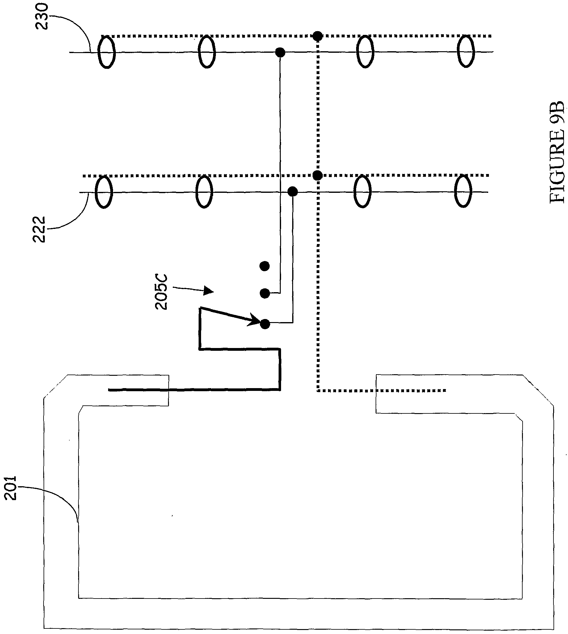


Claims
Priority Applications (7)
| Application Number | Priority Date | Filing Date | Title |
|---|---|---|---|
| KR10-2004-7011493A KR20040089123A (en) | 2002-01-23 | 2003-01-23 | Inventory management system |
| AU2003214872A AU2003214872C1 (en) | 2002-01-23 | 2003-01-23 | Inventory management system |
| CA2474254A CA2474254C (en) | 2002-01-23 | 2003-01-23 | Inventory management system |
| MXPA04007066A MXPA04007066A (en) | 2002-01-23 | 2003-01-23 | Inventory management system. |
| JP2003561322A JP4445265B2 (en) | 2002-01-23 | 2003-01-23 | Inventory management system |
| EP03710711A EP1468473A4 (en) | 2002-01-23 | 2003-01-23 | Inventory management system |
| AU2008221531A AU2008221531B2 (en) | 2002-01-23 | 2008-09-18 | Inventory management system |
Applications Claiming Priority (4)
| Application Number | Priority Date | Filing Date | Title |
|---|---|---|---|
| US34638802P | 2002-01-09 | 2002-01-09 | |
| US35002302P | 2002-01-23 | 2002-01-23 | |
| US60/350,023 | 2002-01-23 | ||
| US10/338,892 | 2003-01-09 |
Publications (2)
| Publication Number | Publication Date |
|---|---|
| WO2003061366A2 true WO2003061366A2 (en) | 2003-07-31 |
| WO2003061366A3 WO2003061366A3 (en) | 2004-03-18 |
Family
ID=26994830
Family Applications (2)
| Application Number | Title | Priority Date | Filing Date |
|---|---|---|---|
| PCT/US2003/000554 WO2003061060A2 (en) | 2002-01-09 | 2003-01-09 | Intelligent station using multiple rf antennae and inventory control system and method incorporating same |
| PCT/US2003/001837 WO2003061366A2 (en) | 2002-01-09 | 2003-01-23 | Inventory management system |
Family Applications Before (1)
| Application Number | Title | Priority Date | Filing Date |
|---|---|---|---|
| PCT/US2003/000554 WO2003061060A2 (en) | 2002-01-09 | 2003-01-09 | Intelligent station using multiple rf antennae and inventory control system and method incorporating same |
Country Status (11)
| Country | Link |
|---|---|
| US (3) | US7084769B2 (en) |
| EP (1) | EP1470613A4 (en) |
| JP (3) | JP2005519491A (en) |
| KR (1) | KR20040096522A (en) |
| CN (2) | CN101957904B (en) |
| AU (1) | AU2003209188B2 (en) |
| CA (2) | CA2801837A1 (en) |
| MX (1) | MXPA04006667A (en) |
| RU (1) | RU2004124049A (en) |
| TW (1) | TWI269235B (en) |
| WO (2) | WO2003061060A2 (en) |
Cited By (24)
| Publication number | Priority date | Publication date | Assignee | Title |
|---|---|---|---|---|
| WO2005053806A2 (en) | 2003-11-17 | 2005-06-16 | Mattel, Inc. | Toy vihecles and play sets with contactless identification |
| EP1600878A2 (en) | 2004-05-27 | 2005-11-30 | Sap Ag | A radio frequency identification (RFID) controller |
| WO2006068338A1 (en) * | 2004-12-20 | 2006-06-29 | Electronics And Telecommunications Research Institute | Real-time business process triggering system and method usingr rfid |
| KR100701644B1 (en) * | 2004-12-14 | 2007-03-30 | 한국전자통신연구원 | System and method for tracking and tracing of objects |
| WO2007061836A2 (en) * | 2005-11-21 | 2007-05-31 | Hewlett-Packard Development Company, L.P. | Method and apparatus for localization of rfid tags |
| KR100730695B1 (en) | 2005-05-13 | 2007-06-21 | 루 리―치 | Automatic inventory management system |
| WO2007086808A2 (en) * | 2006-01-24 | 2007-08-02 | Agency For Science, Technology And Research | System and method for monitoring the status of an inventory item |
| WO2007136353A1 (en) * | 2006-05-24 | 2007-11-29 | Michael Oh Cheng Guan | Movable rfid reading device |
| KR100793455B1 (en) | 2004-10-26 | 2008-01-14 | 교세라 가부시키가이샤 | Transmission control device |
| ITTO20080525A1 (en) * | 2008-07-08 | 2010-01-09 | Garrisonpop S R L | REMOTE MONITORING SYSTEM AND / OR DIFFERENT CONSUMPTION OF ITEMS IN STOCK ON SHELVES AND THE LIKE. |
| WO2011025843A1 (en) * | 2009-08-25 | 2011-03-03 | Maria Estela Seitz | Trans-security components system and methods |
| US7999674B2 (en) | 2007-01-15 | 2011-08-16 | Deka Products Limited Partnership | Device and method for food management |
| CN102645917A (en) * | 2012-03-30 | 2012-08-22 | 山东商业职业技术学院 | Integrated intelligent monitoring system of vehicle-mounted multiple cold accumulation boxes |
| WO2014062457A1 (en) * | 2012-10-19 | 2014-04-24 | Symbol Technologies, Inc. | Method and apparatus for stocking and/or restocking an item |
| WO2014160322A1 (en) * | 2013-03-14 | 2014-10-02 | Impinj, Inc. | Powering rfid tags using multiple systhesized-beam rfid readers |
| WO2015016803A1 (en) * | 2013-07-30 | 2015-02-05 | Chereuchuk Anatolii Anatoliiovych | Method for caring for a living entity |
| CN104408514A (en) * | 2014-11-27 | 2015-03-11 | 深圳市小卫星移动网络科技有限公司 | Intelligent electronic student identity card as well as system and method for shielding telephone in school |
| CN104408507A (en) * | 2014-12-09 | 2015-03-11 | 北京华泰诺安科技有限公司 | Active electronic tag based on power-saving mode |
| CN104408508A (en) * | 2014-12-22 | 2015-03-11 | 陈瑞 | Electronic tag for pipeline |
| EP2812877A4 (en) * | 2012-02-07 | 2015-09-23 | Scott Damon | System and method for tracking inventory of tire components at post-production facility |
| US9916484B2 (en) | 2013-03-14 | 2018-03-13 | Impinj, Inc. | RFID tag location using synthesized-beam RFID readers |
| CN108810161A (en) * | 2018-06-21 | 2018-11-13 | 郑州云海信息技术有限公司 | A kind of storage cabinet system based on cloud computing |
| US10268983B2 (en) | 2013-06-26 | 2019-04-23 | Amazon Technologies, Inc. | Detecting item interaction and movement |
| US10430623B1 (en) | 2013-03-14 | 2019-10-01 | Impinj, Inc. | RFID tag tracking using tag population management |
Families Citing this family (574)
| Publication number | Priority date | Publication date | Assignee | Title |
|---|---|---|---|---|
| US6130602A (en) * | 1996-05-13 | 2000-10-10 | Micron Technology, Inc. | Radio frequency data communications device |
| US6676127B2 (en) | 1997-03-13 | 2004-01-13 | Shuffle Master, Inc. | Collating and sorting apparatus |
| US6254096B1 (en) | 1998-04-15 | 2001-07-03 | Shuffle Master, Inc. | Device and method for continuously shuffling cards |
| US6655684B2 (en) | 1998-04-15 | 2003-12-02 | Shuffle Master, Inc. | Device and method for forming and delivering hands from randomly arranged decks of playing cards |
| US6459726B1 (en) * | 1998-04-24 | 2002-10-01 | Micron Technology, Inc. | Backscatter interrogators, communication systems and backscatter communication methods |
| US6943678B2 (en) * | 2000-01-24 | 2005-09-13 | Nextreme, L.L.C. | Thermoformed apparatus having a communications device |
| US8490973B2 (en) | 2004-10-04 | 2013-07-23 | Shfl Entertainment, Inc. | Card reading shoe with card stop feature and systems utilizing the same |
| US8590896B2 (en) | 2000-04-12 | 2013-11-26 | Shuffle Master Gmbh & Co Kg | Card-handling devices and systems |
| US8511684B2 (en) | 2004-10-04 | 2013-08-20 | Shfl Entertainment, Inc. | Card-reading shoe with inventory correction feature and methods of correcting inventory |
| US8616552B2 (en) | 2001-09-28 | 2013-12-31 | Shfl Entertainment, Inc. | Methods and apparatuses for an automatic card handling device and communication networks including same |
| US8337296B2 (en) | 2001-09-28 | 2012-12-25 | SHFL entertaiment, Inc. | Method and apparatus for using upstream communication in a card shuffler |
| US7753373B2 (en) | 2001-09-28 | 2010-07-13 | Shuffle Master, Inc. | Multiple mode card shuffler and card reading device |
| US7677565B2 (en) | 2001-09-28 | 2010-03-16 | Shuffle Master, Inc | Card shuffler with card rank and value reading capability |
| US20080113783A1 (en) * | 2006-11-10 | 2008-05-15 | Zbigniew Czyzewski | Casino table game monitoring system |
| US20080111300A1 (en) * | 2006-11-10 | 2008-05-15 | Zbigniew Czyzewski | Casino card shoes, systems, and methods for a no peek feature |
| US8011661B2 (en) | 2001-09-28 | 2011-09-06 | Shuffle Master, Inc. | Shuffler with shuffling completion indicator |
| EP1324626A3 (en) * | 2001-12-28 | 2003-12-17 | Matsushita Electric Industrial Co., Ltd. | Control system and method for a wireless communications terminal |
| US20030141962A1 (en) * | 2002-01-25 | 2003-07-31 | Bernard Barink | RFID systems - antenna system and software method to spatially locate transponders |
| US6886829B2 (en) | 2002-02-08 | 2005-05-03 | Vendingdata Corporation | Image capturing card shuffler |
| JP4017424B2 (en) * | 2002-03-25 | 2007-12-05 | 富士通株式会社 | Shelf inspection device, shelf inspection method and shelf inspection program |
| JP2003323539A (en) * | 2002-04-30 | 2003-11-14 | Fujitsu Ltd | Store space management system and information processing device |
| US6933849B2 (en) | 2002-07-09 | 2005-08-23 | Fred Sawyer | Method and apparatus for tracking objects and people |
| WO2004015808A2 (en) * | 2002-08-08 | 2004-02-19 | Burrus, Xavier | Array of modular transmission antennas for an rf identification system |
| EP1537514B1 (en) * | 2002-08-28 | 2006-03-01 | Koninklijke Philips Electronics N.V. | Method of inventorying transponders by means of a communication station |
| US7962361B2 (en) | 2002-11-07 | 2011-06-14 | Novitaz | Customer relationship management system for physical locations |
| US8600804B2 (en) | 2002-11-07 | 2013-12-03 | Novitaz, Inc. | Customer relationship management system for physical locations |
| US7686229B2 (en) | 2003-01-30 | 2010-03-30 | Hewlett-Packard Development Company, L.P. | RFID reader device having closely packed antennas |
| US6796506B1 (en) * | 2003-03-10 | 2004-09-28 | Hewlett-Packard Development Company, L.P. | Tracking electronic devices |
| US6927742B2 (en) * | 2003-03-14 | 2005-08-09 | Aiptek International Inc. | Electromagnetic-induction system with optimum antenna layout and the method for forming the same |
| TW575210U (en) * | 2003-03-28 | 2004-02-01 | Micro Star Int Co Ltd | Wireless network device for computer |
| US20110163857A1 (en) * | 2003-04-09 | 2011-07-07 | Visible Assets, Inc. | Energy Harvesting for Low Frequency Inductive Tagging |
| US8681000B2 (en) | 2003-04-09 | 2014-03-25 | Visible Assets, Inc. | Low frequency inductive tagging for lifecycle management |
| US7675422B2 (en) * | 2003-04-09 | 2010-03-09 | Visible Assets, Inc. | Networked RF Tag for tracking people by means of loyalty cards |
| US7209039B2 (en) * | 2003-05-08 | 2007-04-24 | Illinois Tool Works Inc. | Decorative surface covering with embedded RF antenna and RF shield and method for making the same |
| EP1668741A2 (en) * | 2003-05-09 | 2006-06-14 | MeadWestvaco Corporation | Apparatus for and method of using a close-proximity antenna |
| US7252152B2 (en) * | 2003-06-18 | 2007-08-07 | Weatherford/Lamb, Inc. | Methods and apparatus for actuating a downhole tool |
| US7584016B2 (en) * | 2003-09-30 | 2009-09-01 | Intrinsic Marks International Llc | Item monitoring system and methods |
| US20060244599A1 (en) * | 2003-10-22 | 2006-11-02 | Mobile Aspects, Inc. | Identification apparatus |
| WO2005048181A1 (en) * | 2003-11-04 | 2005-05-26 | Avery Dennison Corporation | Rfid tag with enhanced readability |
| JP4525074B2 (en) * | 2003-12-24 | 2010-08-18 | 日本電気株式会社 | Product identification information management system |
| WO2005069869A2 (en) * | 2004-01-16 | 2005-08-04 | Meadwestvaco Corporation | Systems and methods for prioritizing antennas according to the proximity of an object |
| WO2005071790A2 (en) | 2004-01-16 | 2005-08-04 | Meadwestvaco Corporation | Systems for and methods of assigning priority to reader antennae |
| GB0402240D0 (en) * | 2004-02-02 | 2004-03-03 | Transense Technologies Plc | Remote interrogation of a vehicle wheel |
| JP4519476B2 (en) * | 2004-02-03 | 2010-08-04 | 株式会社東芝 | Wireless communication device |
| US9898712B2 (en) | 2004-02-03 | 2018-02-20 | Rtc Industries, Inc. | Continuous display shelf edge label device |
| US10339495B2 (en) | 2004-02-03 | 2019-07-02 | Rtc Industries, Inc. | System for inventory management |
| US9818148B2 (en) | 2013-03-05 | 2017-11-14 | Rtc Industries, Inc. | In-store item alert architecture |
| US8938396B2 (en) | 2004-02-03 | 2015-01-20 | Rtc Industries, Inc. | System for inventory management |
| WO2005076929A2 (en) | 2004-02-04 | 2005-08-25 | Venture Research, Inc. | Free standing column-shaped structure for housing rfid antennas and readers |
| JP4517674B2 (en) * | 2004-02-25 | 2010-08-04 | パナソニック株式会社 | Wireless communication medium processing apparatus |
| JP4328705B2 (en) * | 2004-02-27 | 2009-09-09 | 均 北吉 | RFID tag device |
| US7398078B2 (en) * | 2004-03-05 | 2008-07-08 | Seknion, Inc. | Method and apparatus for security in a wireless network |
| EP1743271B1 (en) * | 2004-03-05 | 2012-01-18 | Seknion, Inc. | Method and apparatus for improving the efficiency and accuracy of rfid systems |
| ATE458307T1 (en) * | 2004-03-19 | 2010-03-15 | Feig Electronic Gmbh | ELECTRONIC SWITCH FOR HIGH FREQUENCY CONNECTIONS |
| US7301453B2 (en) * | 2004-03-23 | 2007-11-27 | Fry Terry L | Locator system and method |
| EP1745452B1 (en) * | 2004-04-28 | 2008-04-09 | Checkpoint Systems, Inc. | Electronic article tracking system for retail rack using loop antenna |
| US7151455B2 (en) | 2004-04-30 | 2006-12-19 | Kimberly-Clark Worldwide, Inc. | Activating a data tag by load or orientation or user control |
| US7098794B2 (en) | 2004-04-30 | 2006-08-29 | Kimberly-Clark Worldwide, Inc. | Deactivating a data tag for user privacy or tamper-evident packaging |
| US7948381B2 (en) | 2004-04-30 | 2011-05-24 | Binforma Group Limited Liability Company | Reversibly deactivating a radio frequency identification data tag |
| US7102521B2 (en) * | 2004-04-30 | 2006-09-05 | Hewlett-Packard Development Company, L.P. | Method and system for identifying RFID-tagged objects |
| US7102519B2 (en) * | 2004-04-30 | 2006-09-05 | Hewlett-Packard Development Company, L.P. | Concentric tag-reader method and system for RFID |
| US20050258937A1 (en) * | 2004-05-05 | 2005-11-24 | Trenstar, Inc. | Radio frequency identification asset management system and method |
| US7439862B2 (en) | 2004-05-18 | 2008-10-21 | Assa Abloy Ab | Antenna array for an RFID reader compatible with transponders operating at different carrier frequencies |
| US20050280534A1 (en) * | 2004-06-16 | 2005-12-22 | Navarro Pamela W | Clothing item registration system |
| FR2871968B1 (en) * | 2004-06-16 | 2006-09-08 | Gemplus Sa | SYNCHRONOUS PHASE CONTACTLESS DEMODULATION METHOD, DEMODULATOR AND READER |
| EP1774431A4 (en) * | 2004-07-20 | 2009-05-27 | Visible Assets Inc | Rf-enablement of products and receptacles therefor |
| US7432874B2 (en) * | 2004-07-22 | 2008-10-07 | Feig Electronic Gmbh | Antenna array |
| US7348884B2 (en) * | 2004-07-29 | 2008-03-25 | Omnicell, Inc. | RFID cabinet |
| US7246746B2 (en) | 2004-08-03 | 2007-07-24 | Avaya Technology Corp. | Integrated real-time automated location positioning asset management system |
| US7292198B2 (en) | 2004-08-18 | 2007-11-06 | Ruckus Wireless, Inc. | System and method for an omnidirectional planar antenna apparatus with selectable elements |
| US7193562B2 (en) * | 2004-11-22 | 2007-03-20 | Ruckus Wireless, Inc. | Circuit board having a peripheral antenna apparatus with selectable antenna elements |
| US7644016B2 (en) * | 2004-08-25 | 2010-01-05 | Warsaw Orthopedic, Inc. | Automated pass-through surgical instrument tray reader |
| US20060113302A1 (en) * | 2004-09-09 | 2006-06-01 | Inteligistics, Inc. | Modular shipping unit and system |
| US20060066048A1 (en) | 2004-09-14 | 2006-03-30 | Shuffle Master, Inc. | Magnetic jam detection in a card shuffler |
| US20060071791A1 (en) * | 2004-09-29 | 2006-04-06 | Honeywell International Inc. | Enhanced RFID vehicle presence detection system |
| US8085309B1 (en) * | 2004-09-29 | 2011-12-27 | Kelliher Christopher R | GPS enhanced camera for transmitting real-time trail data over a satellite/cellular communication channel |
| US7766332B2 (en) | 2006-07-05 | 2010-08-03 | Shuffle Master, Inc. | Card handling devices and methods of using the same |
| US7357299B2 (en) * | 2004-10-12 | 2008-04-15 | Aristocrat Technologies, Inc. | Method and apparatus for synchronization of proximate RFID readers in a gaming environment |
| US7064668B2 (en) * | 2004-10-25 | 2006-06-20 | The Boeing Company | Reducing electromagnetic interference in radio frequency identification applications |
| US7221269B2 (en) * | 2004-10-29 | 2007-05-22 | Kimberly-Clark Worldwide, Inc. | Self-adjusting portals with movable data tag readers for improved reading of data tags |
| US7623036B2 (en) * | 2004-10-29 | 2009-11-24 | Kimberly-Clark Worldwide, Inc. | Adjusting data tag readers with feed-forward data |
| US7614556B2 (en) | 2004-11-05 | 2009-11-10 | Goliath Solutions, Llc | Distributed RFID antenna array utilizing circular polarized helical antennas |
| WO2006052386A2 (en) * | 2004-11-05 | 2006-05-18 | Goliath Solutions Llc. | Distributed antenna array with centralized data hub for determining presence and location of rf tags |
| US20060109125A1 (en) * | 2004-11-08 | 2006-05-25 | Goliath Solutions Llc. | System for RF detection and location determination of merchandising materials in retail environments |
| US7339476B2 (en) * | 2004-11-10 | 2008-03-04 | Rockwell Automation Technologies, Inc. | Systems and methods that integrate radio frequency identification (RFID) technology with industrial controllers |
| US7551081B2 (en) | 2004-11-10 | 2009-06-23 | Rockwell Automation Technologies, Inc. | Systems and methods that integrate radio frequency identification (RFID) technology with agent-based control systems |
| GB0425008D0 (en) * | 2004-11-12 | 2004-12-15 | Petrowell Ltd | Method and apparatus |
| US20070071131A1 (en) * | 2004-11-18 | 2007-03-29 | Pyne John W | Switched phase receiver for a long range RFID system |
| US7535337B2 (en) * | 2004-11-18 | 2009-05-19 | Goliath Solutions, Llc | Systems and methods for monitoring open stock merchandising |
| US7227469B2 (en) * | 2004-11-22 | 2007-06-05 | Sdgi Holdings, Inc. | Surgical instrument tray shipping tote identification system and methods of using same |
| US7492261B2 (en) * | 2004-11-22 | 2009-02-17 | Warsaw Orthopedic, Inc. | Control system for an RFID-based system for assembling and verifying outbound surgical equipment corresponding to a particular surgery |
| US7492257B2 (en) * | 2004-11-22 | 2009-02-17 | Warsaw Orthopedic, Inc. | Systems and methods for processing surgical instrument tray shipping totes |
| US8049594B1 (en) | 2004-11-30 | 2011-11-01 | Xatra Fund Mx, Llc | Enhanced RFID instrument security |
| US7268684B2 (en) * | 2004-12-08 | 2007-09-11 | Sdgi Holdings, Inc. | Workstation RFID reader for surgical instruments and surgical instrument trays and methods of using same |
| US7358912B1 (en) | 2005-06-24 | 2008-04-15 | Ruckus Wireless, Inc. | Coverage antenna apparatus with selectable horizontal and vertical polarization elements |
| US7387233B2 (en) * | 2004-12-14 | 2008-06-17 | Renesas Technology Corp. | RFID card issuing system |
| US7319398B2 (en) * | 2004-12-15 | 2008-01-15 | Innerspace Corporation | Reconfigurable and replaceable RFID antenna network |
| US7295113B2 (en) | 2004-12-20 | 2007-11-13 | Sap Aktiengesellschaft | Controller for accessing multiple radio frequency identification (RFID) readers |
| WO2006068525A1 (en) * | 2004-12-24 | 2006-06-29 | Edit Id Limited | Improvements in or relating to identification reader systems |
| US7298251B2 (en) * | 2005-01-07 | 2007-11-20 | Honeywell International Inc. | Hand held RFID reader with dipole antenna |
| WO2006075398A1 (en) * | 2005-01-17 | 2006-07-20 | Fujitsu Limited | Communication device and communication method |
| US7893882B2 (en) | 2007-01-08 | 2011-02-22 | Ruckus Wireless, Inc. | Pattern shaping of RF emission patterns |
| CN101111938B (en) | 2005-01-28 | 2010-08-11 | 株式会社半导体能源研究所 | Semiconductor device and method of fabricating the same |
| JP4660219B2 (en) * | 2005-02-01 | 2011-03-30 | パナソニック株式会社 | Non-contact communication reader device |
| US20060187050A1 (en) * | 2005-02-11 | 2006-08-24 | Psc Scanning, Inc. | Loop antenna for RFID |
| US7978060B2 (en) * | 2005-02-14 | 2011-07-12 | Inteligistics, Inc. | Identification system |
| US20060184993A1 (en) * | 2005-02-15 | 2006-08-17 | Goldthwaite Flora P | Method and system for collecting and using data |
| US20060185781A1 (en) * | 2005-02-18 | 2006-08-24 | Mclaughlin Daniel | Apparatus and method for rejecting labels |
| US20060186999A1 (en) * | 2005-02-18 | 2006-08-24 | Ctm Integration, Inc. | Apparatus and method for reading/writing to RFID tags |
| CN102946625A (en) * | 2005-03-03 | 2013-02-27 | 传感电子有限责任公司 | Apparatus for and method of using an intelligent network and RFID signal router |
| US20060197652A1 (en) * | 2005-03-04 | 2006-09-07 | International Business Machines Corporation | Method and system for proximity tracking-based adaptive power control of radio frequency identification (RFID) interrogators |
| US8442433B2 (en) * | 2005-03-30 | 2013-05-14 | At&T Intellectual Property I, Lp | Method and apparatus for provisioning a device |
| US8107625B2 (en) | 2005-03-31 | 2012-01-31 | Avaya Inc. | IP phone intruder security monitoring system |
| DE602006014838D1 (en) | 2005-04-06 | 2010-07-22 | Mallinckrodt Inc | A system for managing information regarding a syringe and a medical fluid |
| JP4812322B2 (en) * | 2005-04-08 | 2011-11-09 | パナソニック株式会社 | Mobile communication device |
| US7837694B2 (en) * | 2005-04-28 | 2010-11-23 | Warsaw Orthopedic, Inc. | Method and apparatus for surgical instrument identification |
| US7362228B2 (en) * | 2005-04-28 | 2008-04-22 | Warsaw Orthepedic, Inc. | Smart instrument tray RFID reader |
| JP4825454B2 (en) * | 2005-05-31 | 2011-11-30 | 株式会社日立国際電気 | Non-contact reader / writer system |
| US7764836B2 (en) | 2005-06-13 | 2010-07-27 | Shuffle Master, Inc. | Card shuffler with card rank and value reading capability using CMOS sensor |
| TWI420428B (en) * | 2005-06-16 | 2013-12-21 | Koninkl Philips Electronics Nv | A wireless system, an rfid objects, and a method of tracking objects |
| US20060289650A1 (en) * | 2005-06-27 | 2006-12-28 | Mobile Aspects, Inc. | Networked monitoring system |
| US7388491B2 (en) | 2005-07-20 | 2008-06-17 | Rockwell Automation Technologies, Inc. | Mobile RFID reader with integrated location awareness for material tracking and management |
| US7764191B2 (en) | 2005-07-26 | 2010-07-27 | Rockwell Automation Technologies, Inc. | RFID tag data affecting automation controller with internal database |
| US8260948B2 (en) * | 2005-08-10 | 2012-09-04 | Rockwell Automation Technologies, Inc. | Enhanced controller utilizing RFID technology |
| US7453363B2 (en) * | 2005-08-19 | 2008-11-18 | Thingmagic, Inc. | RFID reader system incorporating antenna orientation sensing |
| US7336177B2 (en) * | 2005-08-25 | 2008-02-26 | Kimberly-Clark Worldwide, Inc. | RFID system and method for tracking individual articles |
| JP4571555B2 (en) * | 2005-08-25 | 2010-10-27 | 株式会社日立製作所 | Antenna device and reader / writer |
| US7510110B2 (en) * | 2005-09-08 | 2009-03-31 | Rockwell Automation Technologies, Inc. | RFID architecture in an industrial controller environment |
| US8967476B2 (en) * | 2005-09-09 | 2015-03-03 | Assa Abloy Ab | Synchronization techniques in multi-technology/multi-frequency RFID reader arrays |
| US7931197B2 (en) | 2005-09-20 | 2011-04-26 | Rockwell Automation Technologies, Inc. | RFID-based product manufacturing and lifecycle management |
| WO2007035833A2 (en) * | 2005-09-21 | 2007-03-29 | Intermec Ip Corp. | Method, apparatus, and system for selecting and locating objects having radio frequency identification (rfid) tags |
| JP2007087032A (en) * | 2005-09-21 | 2007-04-05 | Toshiba Tec Corp | Wireless tag reader |
| US7446662B1 (en) | 2005-09-26 | 2008-11-04 | Rockwell Automation Technologies, Inc. | Intelligent RFID tag for magnetic field mapping |
| US8025227B2 (en) | 2005-09-30 | 2011-09-27 | Rockwell Automation Technologies, Inc. | Access to distributed databases via pointer stored in RFID tag |
| US7830259B2 (en) * | 2005-10-11 | 2010-11-09 | Nanonation Incorporated | Method and apparatus for RFID initiated interactive retail merchandising |
| JP4569442B2 (en) * | 2005-10-26 | 2010-10-27 | 株式会社デンソーウェーブ | Container box |
| US8159346B2 (en) * | 2005-10-28 | 2012-04-17 | Hitachi, Ltd. | RFID system, RFID cable system, and RFID cable laying method |
| US20070115124A1 (en) * | 2005-11-21 | 2007-05-24 | Cyril Brignone | Determining a state for object identified by an RFID tag |
| US7343265B2 (en) * | 2005-11-23 | 2008-03-11 | Lockheed Martin Corporation | System to monitor the health of a structure, sensor nodes, program product, and related methods |
| GB2475195A (en) | 2005-11-28 | 2011-05-11 | Weatherford Lamb | Method of invoicing for the actual wear to a tubular member |
| CN100458822C (en) * | 2005-11-30 | 2009-02-04 | 中国科学院自动化研究所 | Smart identification terminal system and method based radio-frequency identification and biological characteristic |
| JP2007156937A (en) * | 2005-12-07 | 2007-06-21 | Hitachi Ltd | Radio communication system using electronic tag |
| JP4892962B2 (en) * | 2005-12-22 | 2012-03-07 | オムロン株式会社 | Communication relay device and communication processing device for RFID |
| FR2895839B1 (en) * | 2006-01-03 | 2009-12-18 | Thales Sa | COMPOSITE STRUCTURE HAVING MULTIPLE STACKED LAYERS SUBJECTED TO ELECTROMAGNETIC RADIATION |
| US20070202811A1 (en) * | 2006-01-09 | 2007-08-30 | Benson Chanowitz | System for determining and displaying coverage regionsof an rfid reader/integrator |
| US8447234B2 (en) | 2006-01-18 | 2013-05-21 | Qualcomm Incorporated | Method and system for powering an electronic device via a wireless link |
| US9130602B2 (en) | 2006-01-18 | 2015-09-08 | Qualcomm Incorporated | Method and apparatus for delivering energy to an electrical or electronic device via a wireless link |
| JP4814640B2 (en) * | 2006-01-27 | 2011-11-16 | 富士通株式会社 | RFID reader / writer |
| US7692602B2 (en) * | 2006-02-06 | 2010-04-06 | G-Time Electronic Co., Ltd. | Control system of antenna array of RFID reader applications |
| AU2006338233A1 (en) * | 2006-02-15 | 2007-08-23 | Sensormatic Electronics, LLC | RF switched RFID multiplexer |
| JP4633647B2 (en) * | 2006-02-15 | 2011-02-16 | 株式会社日立製作所 | Control method, control system, and connection confirmation method |
| JP2007221584A (en) * | 2006-02-17 | 2007-08-30 | Nec Corp | Antenna for article management and control method thereof |
| EP1989777A4 (en) | 2006-03-01 | 2011-04-27 | Softmax Inc | System and method for generating a separated signal |
| KR101199142B1 (en) | 2006-03-03 | 2012-11-09 | 엘지이노텍 주식회사 | Distribution administration system using Radio Frequency IDentification |
| US11906988B2 (en) | 2006-03-06 | 2024-02-20 | Deka Products Limited Partnership | Product dispensing system |
| US9146564B2 (en) * | 2006-03-06 | 2015-09-29 | Deka Products Limited Partnership | Product dispensing system |
| US8138891B2 (en) * | 2006-03-07 | 2012-03-20 | Sensormatic Electronics, LLC | RFID network control and redundancy |
| AU2012204104B9 (en) * | 2006-03-07 | 2015-02-12 | Sensormatic Electronics Llc | Network control |
| US8497762B2 (en) * | 2006-03-07 | 2013-07-30 | Tyco Fire & Security Gmbh | Network control |
| US7576657B2 (en) * | 2006-03-22 | 2009-08-18 | Symbol Technologies, Inc. | Single frequency low power RFID device |
| US7556266B2 (en) | 2006-03-24 | 2009-07-07 | Shuffle Master Gmbh & Co Kg | Card shuffler with gravity feed system for playing cards |
| US7806333B1 (en) | 2006-03-27 | 2010-10-05 | Hewlett-Packard Development Company, L.P. | Tracking RFID tags with overlapping antennas |
| US20070221730A1 (en) * | 2006-03-27 | 2007-09-27 | Mcreynolds Alan | RFID enabled cable tracking |
| GB0607052D0 (en) * | 2006-04-07 | 2006-05-17 | Iti Scotland Ltd | Product authentication system |
| US8226003B2 (en) | 2006-04-27 | 2012-07-24 | Sirit Inc. | Adjusting parameters associated with leakage signals |
| US20090176074A1 (en) * | 2006-05-05 | 2009-07-09 | Meadwestvaco Corporation | Conductive/absorbtive sheet materials with enhanced properties |
| US7495560B2 (en) | 2006-05-08 | 2009-02-24 | Corning Cable Systems Llc | Wireless picocellular RFID systems and methods |
| KR100718096B1 (en) * | 2006-05-16 | 2007-05-16 | 삼성전자주식회사 | Communication method between a host and a rfid reader, a host device , a rfid reader and rfid communication system |
| US8472767B2 (en) * | 2006-05-19 | 2013-06-25 | Corning Cable Systems Llc | Fiber optic cable and fiber optic cable assembly for wireless access |
| US7849107B2 (en) * | 2006-05-26 | 2010-12-07 | Symbol Technologies, Inc. | Data format for efficient encoding and access of multiple data items in RFID tags |
| US8353513B2 (en) | 2006-05-31 | 2013-01-15 | Shfl Entertainment, Inc. | Card weight for gravity feed input for playing card shuffler |
| US8579289B2 (en) | 2006-05-31 | 2013-11-12 | Shfl Entertainment, Inc. | Automatic system and methods for accurate card handling |
| US8342525B2 (en) | 2006-07-05 | 2013-01-01 | Shfl Entertainment, Inc. | Card shuffler with adjacent card infeed and card output compartments |
| US20070286599A1 (en) * | 2006-06-12 | 2007-12-13 | Michael Sauer | Centralized optical-fiber-based wireless picocellular systems and methods |
| CN101454787B (en) | 2006-06-14 | 2012-08-15 | 国际商业机器公司 | A method and system for reading a transponder |
| US20070292136A1 (en) * | 2006-06-16 | 2007-12-20 | Michael Sauer | Transponder for a radio-over-fiber optical fiber cable |
| US7385510B2 (en) * | 2006-06-30 | 2008-06-10 | International Business Machines Corporation | Container manifest integrity maintenance system and method |
| US7468650B2 (en) * | 2006-06-30 | 2008-12-23 | International Business Machines Corporation | Methods and systems to improve RFID inventory polling accuracy |
| US8070574B2 (en) | 2007-06-06 | 2011-12-06 | Shuffle Master, Inc. | Apparatus, system, method, and computer-readable medium for casino card handling with multiple hand recall feature |
| US9334820B2 (en) * | 2006-07-11 | 2016-05-10 | Komatsu Ltd. | Working machine component monitoring system |
| WO2008007625A1 (en) * | 2006-07-11 | 2008-01-17 | Komatsu Ltd. | System for monitoring component of operating machine |
| US7551091B2 (en) * | 2006-07-25 | 2009-06-23 | Sensormatic Electronics Corporation | Door with integral antenna |
| US7760093B2 (en) * | 2006-07-26 | 2010-07-20 | Broadcom Corporation | RFID interface and applications thereof |
| ITRM20060404A1 (en) * | 2006-07-27 | 2008-01-28 | Entropia Soluzioni E Rintracci | RFID NETWORK FOR THE TRACEABILITY OF DOCUMENTS AND GOODS |
| CN101118588A (en) * | 2006-08-03 | 2008-02-06 | 西门子(中国)有限公司 | RFID reader and system, method and applied system thereof |
| US20080061940A1 (en) * | 2006-08-03 | 2008-03-13 | Kimberly-Clark Worldwide, Inc. | Smart antenna system for reading data tags |
| EP1892676A1 (en) * | 2006-08-08 | 2008-02-27 | SkiData AG | Access control system |
| DE502006008338D1 (en) * | 2006-08-08 | 2010-12-30 | Skidata Ag | Access control system |
| US20080036601A1 (en) * | 2006-08-11 | 2008-02-14 | Thompson Louis H | Radio frequency integration platform and network therefor |
| US7310070B1 (en) * | 2006-08-23 | 2007-12-18 | Goliath Solutions, Llc | Radio frequency identification shelf antenna with a distributed pattern for localized tag detection |
| GB0616927D0 (en) * | 2006-08-26 | 2006-10-04 | Qinetiq Ltd | Reader apparatus |
| CN101067857A (en) * | 2006-08-28 | 2007-11-07 | 腾讯科技(深圳)有限公司 | Articles-selling system and method for showing goods thereof |
| US20080065496A1 (en) * | 2006-08-29 | 2008-03-13 | Ncr Corporation | Methods and Apparatus for Managing RFID and Other Data |
| JP4918831B2 (en) * | 2006-09-05 | 2012-04-18 | 株式会社日立製作所 | Shelf display and image display method |
| US20080068173A1 (en) * | 2006-09-13 | 2008-03-20 | Sensormatic Electronics Corporation | Radio frequency identification (RFID) system for item level inventory |
| US7787823B2 (en) | 2006-09-15 | 2010-08-31 | Corning Cable Systems Llc | Radio-over-fiber (RoF) optical fiber cable system with transponder diversity and RoF wireless picocellular system using same |
| US20080067244A1 (en) * | 2006-09-20 | 2008-03-20 | Jeffrey Marks | System and method for counting and tracking individuals, animals and objects in defined locations |
| US7887755B2 (en) | 2006-09-20 | 2011-02-15 | Binforma Group Limited Liability Company | Packaging closures integrated with disposable RFID devices |
| US7848654B2 (en) | 2006-09-28 | 2010-12-07 | Corning Cable Systems Llc | Radio-over-fiber (RoF) wireless picocellular system with combined picocells |
| US20080079575A1 (en) * | 2006-09-29 | 2008-04-03 | Sensormatic Electronics Corporation | Distributed radio frequency identification reader and method therefore |
| US7791488B2 (en) * | 2006-10-12 | 2010-09-07 | International Business Machines Corporation | Connectable electronic component comprising a transducer |
| US8010067B2 (en) * | 2006-10-16 | 2011-08-30 | Goliath Solutions, Llc | Long range RFID transmitter power tracking loop |
| US20080094181A1 (en) * | 2006-10-24 | 2008-04-24 | Tagsys Sas | Passive remote control |
| US8919775B2 (en) | 2006-11-10 | 2014-12-30 | Bally Gaming, Inc. | System for billing usage of an automatic card handling device |
| US9789738B2 (en) | 2014-09-29 | 2017-10-17 | Rfmicron, Inc. | Pressure based wireless sensor and applications thereof |
| US8274390B2 (en) | 2006-11-20 | 2012-09-25 | Metrologic Instruments, Inc. | Radio frequency identification antenna switching in a conveyor system |
| JP4953201B2 (en) * | 2007-03-23 | 2012-06-13 | 三菱電線工業株式会社 | RFID gate structure |
| TWI325122B (en) * | 2006-12-04 | 2010-05-21 | Ind Tech Res Inst | Method and system for reading and identifying rfid tag |
| TWI305716B (en) * | 2006-12-06 | 2009-02-01 | Ind Tech Res Inst | Intelligence carrier |
| US8873585B2 (en) | 2006-12-19 | 2014-10-28 | Corning Optical Communications Wireless Ltd | Distributed antenna system for MIMO technologies |
| HK1095702A2 (en) * | 2006-12-28 | 2007-05-11 | Univ Hong Kong Polytechnic | Method for optimizing rfid deployment and rfid deployment optimizer of use thereof |
| US8143996B2 (en) * | 2007-01-08 | 2012-03-27 | The Curators Of The University Of Missouri | Decentralized radio frequency identification system |
| US8073562B2 (en) * | 2007-01-26 | 2011-12-06 | Innovative Picking Technologies, Inc. | Picking system with pick verification |
| US8663779B2 (en) * | 2007-01-31 | 2014-03-04 | Martin Koegl | Formwork panel with frame containing an electronic identification element |
| US20080186174A1 (en) * | 2007-02-02 | 2008-08-07 | Sensormatic Electronics Corporation | Item level inventory with a radio frequency identification (RFID) system |
| JP5105889B2 (en) * | 2007-02-06 | 2012-12-26 | サンデン株式会社 | RFID tag reader and adjustment method thereof |
| US8111998B2 (en) | 2007-02-06 | 2012-02-07 | Corning Cable Systems Llc | Transponder systems and methods for radio-over-fiber (RoF) wireless picocellular systems |
| US9774086B2 (en) | 2007-03-02 | 2017-09-26 | Qualcomm Incorporated | Wireless power apparatus and methods |
| US7752089B2 (en) * | 2007-03-02 | 2010-07-06 | The Curators Of The University Of Missouri | Adaptive inventory management system |
| JP2008226042A (en) * | 2007-03-14 | 2008-09-25 | Fujitsu Ltd | Circulation management system, circulation management device, circulation management method and circulation management program |
| JP2008226093A (en) * | 2007-03-15 | 2008-09-25 | Sanden Corp | Adjusting method of rfid tag reader |
| JP2008244569A (en) * | 2007-03-26 | 2008-10-09 | Sanden Corp | Rfid tag reader |
| EP1973083A3 (en) * | 2007-03-20 | 2009-04-15 | Sanden Corporation | Electronic money charger |
| US20080231438A1 (en) * | 2007-03-23 | 2008-09-25 | Diamond Arrow Communications L.L.C. | Cargo Container Monitoring System |
| US20080231454A1 (en) * | 2007-03-23 | 2008-09-25 | Diamond Arrow Communications L.L.C. | Cargo Container Monitoring Device |
| JP2008242857A (en) * | 2007-03-27 | 2008-10-09 | Brother Ind Ltd | Radio tag information reading device |
| US7825867B2 (en) * | 2007-04-26 | 2010-11-02 | Round Rock Research, Llc | Methods and systems of changing antenna polarization |
| WO2008135641A1 (en) * | 2007-05-04 | 2008-11-13 | Supertec | System for reading rfid tags and showcase for this system |
| US10262168B2 (en) | 2007-05-09 | 2019-04-16 | Weatherford Technology Holdings, Llc | Antenna for use in a downhole tubular |
| US7525487B2 (en) * | 2007-05-17 | 2009-04-28 | Yeon Technologies Co., Ltd. | RFID shelf antennas |
| ITUD20070084A1 (en) * | 2007-05-17 | 2008-11-18 | Immobiliare Metalprogetti Srl | AUTOMATIC DISTRIBUTOR DEVICE FOR OBJECTS |
| US8248212B2 (en) | 2007-05-24 | 2012-08-21 | Sirit Inc. | Pipelining processes in a RF reader |
| US8085150B2 (en) * | 2007-05-29 | 2011-12-27 | Rcd Technology Inc | Inventory system for RFID tagged objects |
| US8044804B1 (en) | 2007-06-01 | 2011-10-25 | Hewlett-Packard Development Company, L. P. | Localizing a tag using variable signal range |
| DE102007026155A1 (en) * | 2007-06-04 | 2009-01-08 | Fraunhofer-Gesellschaft zur Förderung der angewandten Forschung e.V. | Method for recording process parameters and wood-based product |
| WO2008148226A1 (en) * | 2007-06-06 | 2008-12-11 | Elektrobit Wireless Communications Ltd. | Rfid read-write station and method for operation of same |
| US9124120B2 (en) | 2007-06-11 | 2015-09-01 | Qualcomm Incorporated | Wireless power system and proximity effects |
| GB2450531B (en) * | 2007-06-29 | 2012-02-29 | Avonwood Dev Ltd | An RFID monitoring system |
| US8098485B2 (en) * | 2007-07-03 | 2012-01-17 | 3M Innovative Properties Company | Wireless network sensors for detecting events occurring proximate the sensors |
| US8035511B2 (en) * | 2007-07-03 | 2011-10-11 | 3M Innovative Properties Company | Methods for providing services and information based upon data collected via wireless network sensors |
| US8026808B2 (en) | 2007-07-03 | 2011-09-27 | 3M Innovative Properties Company | Display of information related to data collected via wireless network sensors |
| US8013731B2 (en) * | 2007-07-03 | 2011-09-06 | 3M Innovative Properties Company | Apparatus and method for processing data collected via wireless network sensors |
| US20100054746A1 (en) | 2007-07-24 | 2010-03-04 | Eric Raymond Logan | Multi-port accumulator for radio-over-fiber (RoF) wireless picocellular systems |
| JP4488040B2 (en) | 2007-07-26 | 2010-06-23 | Tdk株式会社 | Radio communication transmitter / receiver, RFID system, and radio communication transmitter / receiver reception method |
| US20090027202A1 (en) * | 2007-07-27 | 2009-01-29 | Sensormatic Electronics Corporation | Rfid system with integrated switched antenna array and multiplexer electronics |
| ITTO20070585A1 (en) * | 2007-08-03 | 2009-02-04 | Basicnet S P A | SYSTEM AND METHOD OF ORGANIZING THE SALE OF CLOTHING ARTICLES, PARTICULARLY FOOTWEAR AND SIMILAR |
| WO2009023155A2 (en) | 2007-08-09 | 2009-02-19 | Nigelpower, Llc | Increasing the q factor of a resonator |
| US8400269B2 (en) * | 2007-08-30 | 2013-03-19 | Round Rock Research, Llc | Methods and systems using polarization modulated electromagnetic waves |
| US7936268B2 (en) * | 2007-08-31 | 2011-05-03 | Round Rock Research, Llc | Selectively coupling to feed points of an antenna system |
| US8730121B2 (en) * | 2007-08-31 | 2014-05-20 | Tyco Fire & Security Gmbh | Large scale folded dipole antenna for near-field RFID applications |
| CN101377808B (en) * | 2007-08-31 | 2012-02-29 | 天时电子股份有限公司 | Radio frequency identification positioning apparatus and method |
| TW200910681A (en) * | 2007-08-31 | 2009-03-01 | Yfy Rfid Technologies Company Ltd | Antenna supporter, antenna assembly and machine having the antenna assembly |
| AU2014221256B2 (en) * | 2007-09-06 | 2016-05-05 | Deka Products Limited Partnership | RFID system and method |
| EP2188203B1 (en) * | 2007-09-06 | 2016-07-27 | DEKA Products Limited Partnership | Beverage dispensing system |
| EP2188753B1 (en) * | 2007-09-06 | 2018-11-07 | DEKA Products Limited Partnership | Processing system and method |
| CN101849320B (en) | 2007-09-06 | 2015-12-16 | 德卡产品有限公司 | Rfid system and method |
| US10859072B2 (en) | 2007-09-06 | 2020-12-08 | Deka Products Limited Partnership | Product dispensing system |
| US11634311B2 (en) | 2007-09-06 | 2023-04-25 | Deka Products Limited Partnership | Product dispensing system |
| US10562757B2 (en) | 2007-09-06 | 2020-02-18 | Deka Products Limited Partnership | Product dispensing system |
| US8314740B2 (en) * | 2007-09-06 | 2012-11-20 | Deka Products Limited Partnership | RFID system |
| JP2010539821A (en) | 2007-09-13 | 2010-12-16 | クゥアルコム・インコーポレイテッド | Maximizing the power generated from wireless power magnetic resonators |
| CN101828300A (en) | 2007-09-17 | 2010-09-08 | 高通股份有限公司 | Transmitters and receivers for wireless energy transfer |
| US8400319B2 (en) * | 2007-09-24 | 2013-03-19 | John Mezzalingua Associates, Inc. | Coaxial cable connector with an external sensor and method of use thereof |
| US8570178B2 (en) * | 2007-09-24 | 2013-10-29 | Ppc Broadband, Inc. | Coaxial cable connector with internal floating ground circuitry and method of use thereof |
| US7830322B1 (en) | 2007-09-24 | 2010-11-09 | Impinj, Inc. | RFID reader antenna assembly |
| US8400318B2 (en) * | 2007-09-24 | 2013-03-19 | John Mezzalingua Associates, Inc. | Method for determining electrical power signal levels in a transmission system |
| EP2195880A4 (en) * | 2007-09-24 | 2013-02-13 | Cooper Tire & Rubber Co | Automatic antenna tuner system for rfid |
| US8149127B2 (en) * | 2007-09-24 | 2012-04-03 | John Mezzalingua Associates, Inc. | Coaxial cable connector with an internal coupler and method of use thereof |
| US8773255B2 (en) * | 2007-09-24 | 2014-07-08 | Ppc Broadband, Inc. | Status sensing and reporting interface |
| US8289163B2 (en) * | 2007-09-27 | 2012-10-16 | 3M Innovative Properties Company | Signal line structure for a radio-frequency identification system |
| US20110273360A1 (en) | 2007-10-08 | 2011-11-10 | Sensormatic Electronics, LLC | Combination radio frequency identification and electronic article surveillance antenna system |
| KR101507265B1 (en) | 2007-10-11 | 2015-03-30 | 퀄컴 인코포레이티드 | Wireless power transfer using magneto mechanical systems |
| US8717244B2 (en) * | 2007-10-11 | 2014-05-06 | 3M Innovative Properties Company | RFID tag with a modified dipole antenna |
| US8175459B2 (en) | 2007-10-12 | 2012-05-08 | Corning Cable Systems Llc | Hybrid wireless/wired RoF transponder and hybrid RoF communication system using same |
| US20090096585A1 (en) * | 2007-10-12 | 2009-04-16 | Symbol Technologies, Inc. | Methods, Systems and Apparatus for Radio Frequency Identification (RFID) System Configuration Management |
| GB0720421D0 (en) | 2007-10-19 | 2007-11-28 | Petrowell Ltd | Method and apparatus for completing a well |
| US20090102610A1 (en) * | 2007-10-22 | 2009-04-23 | The Stanley Works | Rfid antenna selection system and method |
| EP2217978B1 (en) * | 2007-10-31 | 2016-02-24 | Corts Engineering GmbH & Co. KG | Rfid system and bearing components for rolling mill |
| WO2009081303A1 (en) * | 2007-12-19 | 2009-07-02 | Koninklijke Philips Electronics, N.V. | Identification of objects using frequency characteristics of rfid tags |
| WO2009081376A2 (en) | 2007-12-20 | 2009-07-02 | Mobileaccess Networks Ltd. | Extending outdoor location based services and applications into enclosed areas |
| KR100942120B1 (en) * | 2008-02-05 | 2010-02-12 | 엘에스산전 주식회사 | Radio frequency identification antenna and apparatus for managing article using the same |
| US9123069B1 (en) | 2008-02-11 | 2015-09-01 | Amazon Technologies, Inc. | Moving transaction details forward in buying process |
| GB0804306D0 (en) | 2008-03-07 | 2008-04-16 | Petrowell Ltd | Device |
| US8427316B2 (en) | 2008-03-20 | 2013-04-23 | 3M Innovative Properties Company | Detecting tampered with radio frequency identification tags |
| JP5114263B2 (en) * | 2008-03-26 | 2013-01-09 | 理想科学工業株式会社 | Open container with recording medium |
| US8629576B2 (en) | 2008-03-28 | 2014-01-14 | Qualcomm Incorporated | Tuning and gain control in electro-magnetic power systems |
| JP2009250480A (en) * | 2008-04-03 | 2009-10-29 | Mitsubishi Electric Corp | Storage and refrigerator |
| US8446256B2 (en) | 2008-05-19 | 2013-05-21 | Sirit Technologies Inc. | Multiplexing radio frequency signals |
| EP2311141B1 (en) | 2008-05-20 | 2018-02-21 | DEKA Products Limited Partnership | Rfid system |
| US8115637B2 (en) | 2008-06-03 | 2012-02-14 | Micron Technology, Inc. | Systems and methods to selectively connect antennas to receive and backscatter radio frequency signals |
| US8120486B2 (en) * | 2008-06-10 | 2012-02-21 | Symbol Technologies, Inc. | Methods and systems for tracking RFID devices |
| WO2009149506A1 (en) | 2008-06-12 | 2009-12-17 | Magellan Technology Pty Ltd. | Antenna design and interrogator system |
| JP2010020685A (en) * | 2008-07-14 | 2010-01-28 | Sanden Corp | Antenna device for rfid tag |
| US20110140842A1 (en) * | 2009-12-15 | 2011-06-16 | Morton Greene | System and method for identifying a genuine printed document |
| US20100017851A1 (en) * | 2008-07-16 | 2010-01-21 | Morton Greene | System and process for registering and later confirming a written or printed document is genuine and unaltered, while mitigating the risk of its loss |
| US9773362B2 (en) | 2008-08-08 | 2017-09-26 | Assa Abloy Ab | Directional sensing mechanism and communications authentication |
| WO2010017552A1 (en) * | 2008-08-08 | 2010-02-11 | Assa Abloy Ab | Directional sensing mechanism and communications authentication |
| US9208306B2 (en) | 2008-08-08 | 2015-12-08 | Assa Abloy Ab | Directional sensing mechanism and communications authentication |
| US7777674B1 (en) * | 2008-08-20 | 2010-08-17 | L-3 Communications, Corp. | Mobile distributed antenna array for wireless communication |
| WO2010025382A2 (en) | 2008-08-28 | 2010-03-04 | Deka Products Limited Partnership | Product dispensing system |
| US20100079248A1 (en) * | 2008-09-29 | 2010-04-01 | Johannes Ian Greveling | Optical fiber connector assembly with wire-based RFID antenna |
| US8414471B2 (en) | 2008-10-28 | 2013-04-09 | Mobile Aspects, Inc. | Endoscope storage cabinet, tracking system, and signal emitting member |
| TW201038166A (en) * | 2008-11-14 | 2010-10-16 | Corning Inc | Equipment cabinet having improved space utilization |
| US8414326B2 (en) * | 2008-11-17 | 2013-04-09 | Rochester Institute Of Technology | Internal coaxial cable connector integrated circuit and method of use thereof |
| US8303334B2 (en) * | 2008-11-17 | 2012-11-06 | John Mezzalingua Associates, Inc. | Embedded coupler device and method of use thereof |
| US8419464B2 (en) * | 2008-11-17 | 2013-04-16 | Ppc Broadband, Inc. | Coaxial connector with integrated molded substrate and method of use thereof |
| US8376774B2 (en) * | 2008-11-17 | 2013-02-19 | Rochester Institute Of Technology | Power extracting device and method of use thereof |
| KR20100056159A (en) * | 2008-11-19 | 2010-05-27 | 삼성전자주식회사 | Radio frequency identification apparatus for applying a plurality of radio frequency identification schemes |
| KR100979405B1 (en) * | 2008-12-30 | 2010-09-02 | 주식회사 열림기술 | Repeater for detecting entrance and exit and system having the same for providing location information of a child |
| BRPI0924115A2 (en) * | 2009-01-07 | 2016-10-04 | Panasonic Corp | reader / writer |
| US8169312B2 (en) | 2009-01-09 | 2012-05-01 | Sirit Inc. | Determining speeds of radio frequency tags |
| US9673904B2 (en) | 2009-02-03 | 2017-06-06 | Corning Optical Communications LLC | Optical fiber-based distributed antenna systems, components, and related methods for calibration thereof |
| JP2012517190A (en) | 2009-02-03 | 2012-07-26 | コーニング ケーブル システムズ リミテッド ライアビリティ カンパニー | Fiber optic based distributed antenna system, components and related methods for monitoring and configuration thereof |
| JP5480916B2 (en) | 2009-02-03 | 2014-04-23 | コーニング ケーブル システムズ リミテッド ライアビリティ カンパニー | Fiber optic based distributed antenna system, components, and related methods for calibration thereof |
| CA2737935C (en) | 2009-02-11 | 2017-10-24 | William W. Segiet | Beverage dispense valve controlled by wireless technology |
| US8446253B2 (en) * | 2009-03-11 | 2013-05-21 | Checkpoint Systems, Inc. | Localization using virtual antenna arrays in modulated backscatter RFID systems |
| JP2010231615A (en) * | 2009-03-27 | 2010-10-14 | Toshiba Tec Corp | Information processing apparatus |
| US8598988B2 (en) * | 2009-03-27 | 2013-12-03 | Osa Acquisition, Llc | Systems and methods for controlling serially connected transmitters in RFID tag tracking |
| US7988152B2 (en) | 2009-04-07 | 2011-08-02 | Shuffle Master, Inc. | Playing card shuffler |
| US8967621B2 (en) | 2009-04-07 | 2015-03-03 | Bally Gaming, Inc. | Card shuffling apparatuses and related methods |
| US8558669B2 (en) * | 2009-04-12 | 2013-10-15 | Megabyte Ltd. | Radio frequency identification reader |
| EP2244333B1 (en) * | 2009-04-24 | 2013-11-13 | Spacecode | RFID system |
| US8416079B2 (en) | 2009-06-02 | 2013-04-09 | 3M Innovative Properties Company | Switching radio frequency identification (RFID) tags |
| US8339244B2 (en) * | 2009-06-15 | 2012-12-25 | Trapeze Networks, Inc. | Asset tag power optimization |
| US9590733B2 (en) * | 2009-07-24 | 2017-03-07 | Corning Optical Communications LLC | Location tracking using fiber optic array cables and related systems and methods |
| US8548330B2 (en) | 2009-07-31 | 2013-10-01 | Corning Cable Systems Llc | Sectorization in distributed antenna systems, and related components and methods |
| GB0914650D0 (en) | 2009-08-21 | 2009-09-30 | Petrowell Ltd | Apparatus and method |
| JP2013503551A (en) * | 2009-08-28 | 2013-01-31 | テレコム・マレーシア・バーハド | Improved high frequency antenna |
| JP4985732B2 (en) * | 2009-09-01 | 2012-07-25 | 日本電気株式会社 | IC tag reading / writing device, electronic device, and IC tag reading / writing method |
| US8284059B2 (en) * | 2009-09-21 | 2012-10-09 | Carefusion 303, Inc. | Inventory monitoring and verification system |
| MX2012003457A (en) | 2009-09-21 | 2012-08-03 | Checkpoint Systems Inc | Retail product tracking system, method, and apparatus. |
| US8508367B2 (en) | 2009-09-21 | 2013-08-13 | Checkpoint Systems, Inc. | Configurable monitoring device |
| US8395508B2 (en) * | 2009-09-23 | 2013-03-12 | Wistron Neweb Corporation | RFID tag monitoring system |
| US9319214B2 (en) * | 2009-10-07 | 2016-04-19 | Rf Micro Devices, Inc. | Multi-mode power amplifier architecture |
| TWI408908B (en) | 2009-10-22 | 2013-09-11 | Ind Tech Res Inst | Antenna switch and antenna switching method thereof |
| US8280259B2 (en) | 2009-11-13 | 2012-10-02 | Corning Cable Systems Llc | Radio-over-fiber (RoF) system for protocol-independent wired and/or wireless communication |
| US8618944B2 (en) * | 2009-12-03 | 2013-12-31 | Ppc Broadband, Inc. | Coaxial cable connector parameter monitoring system |
| US8215550B2 (en) * | 2009-12-18 | 2012-07-10 | Motorola Solutions, Inc. | Orienting a scanning device with respect to a target location |
| US10977965B2 (en) | 2010-01-29 | 2021-04-13 | Avery Dennison Retail Information Services, Llc | Smart sign box using electronic interactions |
| EP2529366B1 (en) | 2010-01-29 | 2016-11-09 | Avery Dennison Corporation | Smart sign box using electronic interactions |
| US8275265B2 (en) | 2010-02-15 | 2012-09-25 | Corning Cable Systems Llc | Dynamic cell bonding (DCB) for radio-over-fiber (RoF)-based networks and communication systems and related methods |
| US8313028B2 (en) * | 2010-02-17 | 2012-11-20 | On Track Innovations Ltd. | Multiple antenna reading system suitable for use with contactless transaction devices |
| BR112012021554A2 (en) * | 2010-02-26 | 2016-08-16 | Deka Products Lp | rfid system with eddy current trap |
| US20110248823A1 (en) | 2010-04-07 | 2011-10-13 | Kristian Silberbauer | Asset identification and tracking system and method |
| KR101821904B1 (en) * | 2010-04-08 | 2018-01-24 | 액세스 비지니스 그룹 인터내셔날 엘엘씨 | Point of sale inductive systems and methods |
| US9525488B2 (en) | 2010-05-02 | 2016-12-20 | Corning Optical Communications LLC | Digital data services and/or power distribution in optical fiber-based distributed communications systems providing digital data and radio frequency (RF) communications services, and related components and methods |
| US20110268446A1 (en) | 2010-05-02 | 2011-11-03 | Cune William P | Providing digital data services in optical fiber-based distributed radio frequency (rf) communications systems, and related components and methods |
| US8723653B2 (en) | 2010-05-27 | 2014-05-13 | Schneider Electric It Corporation | Asset identification and management method and system |
| CN101957925B (en) * | 2010-06-11 | 2016-06-01 | 刘守兵 | Multiple-unit combination aerial array RFID positioning identification system |
| US8410909B2 (en) | 2010-07-09 | 2013-04-02 | Corning Incorporated | Cables and connector assemblies employing a furcation tube(s) for radio-frequency identification (RFID)-equipped connectors, and related systems and methods |
| US8648699B2 (en) | 2010-07-19 | 2014-02-11 | Mobile Aspects, Inc. | Item tracking system and arrangement |
| US20120024669A1 (en) | 2010-07-29 | 2012-02-02 | Danelski Darin L | Networked Motorized Drive Roller Conveyor |
| WO2012024247A1 (en) | 2010-08-16 | 2012-02-23 | Corning Cable Systems Llc | Remote antenna clusters and related systems, components, and methods supporting digital data signal propagation between remote antenna units |
| US9252874B2 (en) | 2010-10-13 | 2016-02-02 | Ccs Technology, Inc | Power management for remote antenna units in distributed antenna systems |
| US8800993B2 (en) | 2010-10-14 | 2014-08-12 | Shuffle Master Gmbh & Co Kg | Card handling systems, devices for use in card handling systems and related methods |
| CA2801402A1 (en) * | 2010-11-11 | 2012-05-18 | Zhejiang Tuwei Electricity Technology Co., Ltd | Technology and device for precisely measuring temperature of cable joint on the basis of radio frequency technique |
| KR20120057835A (en) * | 2010-11-29 | 2012-06-07 | 한국전자통신연구원 | Apparatus of RFID electronic shelf and method of detecting the location of the tag using the same |
| US9251390B2 (en) * | 2010-12-06 | 2016-02-02 | Ncr Corporation | Item identification device antenna |
| US8587407B2 (en) * | 2010-12-06 | 2013-11-19 | Ncr Corporation | Media transaction kiosk and method |
| US8604936B2 (en) | 2010-12-13 | 2013-12-10 | Ppc Broadband, Inc. | Coaxial cable connector, system and method of use thereof |
| US8519848B2 (en) * | 2010-12-22 | 2013-08-27 | Symbol Technologies, Inc. | RFID-based inventory monitoring systems and methods with self-adjusting operational parameters |
| US11182661B2 (en) | 2011-01-06 | 2021-11-23 | Maplebear Inc. | Reader network system for presence management in a physical retail environment |
| CN203504582U (en) | 2011-02-21 | 2014-03-26 | 康宁光缆系统有限责任公司 | Distributed antenna system and power supply apparatus for distributing electric power thereof |
| EP2695071A4 (en) * | 2011-03-17 | 2016-09-07 | Patrick Campbell | On-shelf tracking (ost) system |
| US10378956B2 (en) | 2011-03-17 | 2019-08-13 | Triangle Strategy Group, LLC | System and method for reducing false positives caused by ambient lighting on infra-red sensors, and false positives caused by background vibrations on weight sensors |
| US10083453B2 (en) | 2011-03-17 | 2018-09-25 | Triangle Strategy Group, LLC | Methods, systems, and computer readable media for tracking consumer interactions with products using modular sensor units |
| AU2012228977A1 (en) * | 2011-03-17 | 2013-09-19 | Patrick Campbell | On-shelf tracking (OST) system |
| WO2012147261A1 (en) * | 2011-04-28 | 2012-11-01 | 村田機械株式会社 | Article receiving system, and article receiving and shipment method |
| EP2702710A4 (en) | 2011-04-29 | 2014-10-29 | Corning Cable Sys Llc | Determining propagation delay of communications in distributed antenna systems, and related components, systems and methods |
| CN103609146B (en) | 2011-04-29 | 2017-05-31 | 康宁光缆系统有限责任公司 | For increasing the radio frequency in distributing antenna system(RF)The system of power, method and apparatus |
| JP5881973B2 (en) * | 2011-05-13 | 2016-03-09 | エフ・アイ・ティー・パシフィック株式会社 | Position information management system for rack mounted equipment |
| US10311395B2 (en) * | 2011-06-07 | 2019-06-04 | Deroyal Industries, Inc. | Inventory data management system |
| EP2535850B1 (en) * | 2011-06-16 | 2019-01-23 | Deutsche Post AG | Logistic terminal with loading dock areas suitable to identify objects |
| KR101216841B1 (en) * | 2011-07-08 | 2012-12-28 | 엘에스산전 주식회사 | Shelf-shaped rfid system |
| US9239942B2 (en) * | 2011-07-22 | 2016-01-19 | Avery Dennison Corporation | Apparatus, system and method for extending the field area of a device equipped with a high-frequency reader |
| US9731190B2 (en) | 2011-07-29 | 2017-08-15 | Bally Gaming, Inc. | Method and apparatus for shuffling and handling cards |
| US8485527B2 (en) | 2011-07-29 | 2013-07-16 | Savant Shuffler LLC | Card shuffler |
| CN104025556B (en) | 2011-09-01 | 2018-08-10 | 艾利丹尼森公司 | Equipment, system and method for consumer's tracking |
| TWI423138B (en) * | 2011-09-26 | 2014-01-11 | China Steel Corp | Radio frequency identification tag grouping system |
| US8630908B2 (en) | 2011-11-02 | 2014-01-14 | Avery Dennison Corporation | Distributed point of sale, electronic article surveillance, and product information system, apparatus and method |
| GB2496913B (en) | 2011-11-28 | 2018-02-21 | Weatherford Uk Ltd | Torque limiting device |
| JPWO2013080507A1 (en) * | 2011-12-02 | 2015-04-27 | 日本電気株式会社 | Communication sheet, smart shelf |
| US9246203B2 (en) * | 2011-12-02 | 2016-01-26 | Nec Corporation | Communication sheet, smart shelf |
| CN103164714B (en) * | 2011-12-08 | 2016-04-20 | 鸿富锦精密工业(深圳)有限公司 | Wireless radio frequency identification reader-writer and there is the radio frequency identification system of this read write line |
| US10229383B2 (en) | 2012-02-05 | 2019-03-12 | Matthews International Corporation | Perpetual batch order fulfillment |
| US9446908B2 (en) | 2012-02-05 | 2016-09-20 | Matthews Resources, Inc. | Conveying systems and methods of associating data with an item transported by a conveying system |
| US9634403B2 (en) | 2012-02-14 | 2017-04-25 | Ruckus Wireless, Inc. | Radio frequency emission pattern shaping |
| US10186750B2 (en) | 2012-02-14 | 2019-01-22 | Arris Enterprises Llc | Radio frequency antenna array with spacing element |
| US10062025B2 (en) | 2012-03-09 | 2018-08-28 | Neology, Inc. | Switchable RFID tag |
| EP2642423B1 (en) | 2012-03-22 | 2015-06-10 | Nxp B.V. | Combined multifunctional RFID communication device |
| EP2832012A1 (en) | 2012-03-30 | 2015-02-04 | Corning Optical Communications LLC | Reducing location-dependent interference in distributed antenna systems operating in multiple-input, multiple-output (mimo) configuration, and related components, systems, and methods |
| WO2013162988A1 (en) | 2012-04-25 | 2013-10-31 | Corning Cable Systems Llc | Distributed antenna system architectures |
| US9755311B2 (en) * | 2012-05-29 | 2017-09-05 | Samsung Electronics Co., Ltd. | Circularly polarized patch antennas, antenna arrays, and devices including such antennas and arrays |
| US20130325673A1 (en) * | 2012-06-05 | 2013-12-05 | Microsoft Corporation | Coordinate model for inventory visualization in conjunction with physical layout |
| US8960674B2 (en) | 2012-07-27 | 2015-02-24 | Bally Gaming, Inc. | Batch card shuffling apparatuses including multi-card storage compartments, and related methods |
| EP2883416A1 (en) | 2012-08-07 | 2015-06-17 | Corning Optical Communications Wireless Ltd. | Distribution of time-division multiplexed (tdm) management services in a distributed antenna system, and related components, systems, and methods |
| NO336454B1 (en) * | 2012-08-31 | 2015-08-24 | Id Tag Technology Group As | Device, system and method for identifying objects in a digital image, as well as transponder device |
| US9734365B2 (en) | 2012-09-10 | 2017-08-15 | Avery Dennison Retail Information Services, Llc | Method for preventing unauthorized diversion of NFC tags |
| US20140085052A1 (en) * | 2012-09-27 | 2014-03-27 | Interstate Battery System International, Inc. | Modular rfid tag scanner for a product storage system |
| US9511274B2 (en) | 2012-09-28 | 2016-12-06 | Bally Gaming Inc. | Methods for automatically generating a card deck library and master images for a deck of cards, and a related card processing apparatus |
| US9378766B2 (en) | 2012-09-28 | 2016-06-28 | Bally Gaming, Inc. | Card recognition system, card handling device, and method for tuning a card handling device |
| CN102868237B (en) * | 2012-09-28 | 2014-12-24 | 清华大学 | Circuit for improving energy transmission efficiency of non-contact type IC (integrated circuit) card |
| US10540527B2 (en) | 2012-10-18 | 2020-01-21 | Avery Dennison Retail Information Services Llc | Method, system and apparatus for NFC security |
| US9455784B2 (en) | 2012-10-31 | 2016-09-27 | Corning Optical Communications Wireless Ltd | Deployable wireless infrastructures and methods of deploying wireless infrastructures |
| EP2795950B1 (en) | 2012-11-19 | 2018-09-05 | Avery Dennison Corporation | Nfc security system and method for disabling unauthorized tags |
| AU2013344345B2 (en) | 2012-11-19 | 2017-03-23 | Omnicell, Inc. | Storage cabinet with multiple RFID readers |
| WO2014085115A1 (en) | 2012-11-29 | 2014-06-05 | Corning Cable Systems Llc | HYBRID INTRA-CELL / INTER-CELL REMOTE UNIT ANTENNA BONDING IN MULTIPLE-INPUT, MULTIPLE-OUTPUT (MIMO) DISTRIBUTED ANTENNA SYSTEMS (DASs) |
| US9647758B2 (en) | 2012-11-30 | 2017-05-09 | Corning Optical Communications Wireless Ltd | Cabling connectivity monitoring and verification |
| CN105190655B (en) | 2013-03-04 | 2018-05-18 | 日本电气株式会社 | Article management system, information processing equipment and its control method and control program |
| US10357118B2 (en) * | 2013-03-05 | 2019-07-23 | Rtc Industries, Inc. | Systems and methods for merchandizing electronic displays |
| US9361493B2 (en) | 2013-03-07 | 2016-06-07 | Applied Wireless Identifications Group, Inc. | Chain antenna system |
| US9031872B1 (en) | 2013-03-12 | 2015-05-12 | Target Brands, Inc. | Digital sign with incorrectly stocked item identification |
| US20140270284A1 (en) * | 2013-03-13 | 2014-09-18 | Aliphcom | Characteristic-based communications |
| US9656803B2 (en) * | 2013-03-13 | 2017-05-23 | Symbotic, LLC | Storage and retrieval system rover interface |
| US9443218B2 (en) | 2013-03-15 | 2016-09-13 | Wal-Mart Stores, Inc. | Merchandise event monitoring via wireless tracking |
| US9092679B2 (en) | 2013-03-15 | 2015-07-28 | Wal-Mart Stores, Inc. | RFID reader location self-discovery |
| CA2903717C (en) * | 2013-03-15 | 2019-04-02 | Wal-Mart Stores, Inc. | Misplaced item determination using radio frequency identification data |
| US9098824B2 (en) | 2013-03-15 | 2015-08-04 | Wal-Mart Stores, Inc. | Orphaned product stray analysis using RFID |
| US9520643B2 (en) * | 2013-04-10 | 2016-12-13 | Apple Inc. | Electronic device with foam antenna carrier |
| CN103231885A (en) * | 2013-04-15 | 2013-08-07 | 深圳市海云天科技股份有限公司 | Goods counting and distributing device and system |
| EP2797024B1 (en) * | 2013-04-23 | 2018-03-28 | Bundesdruckerei GmbH | Mobile proximity coupling device |
| EP3008515A1 (en) | 2013-06-12 | 2016-04-20 | Corning Optical Communications Wireless, Ltd | Voltage controlled optical directional coupler |
| EP3008828B1 (en) | 2013-06-12 | 2017-08-09 | Corning Optical Communications Wireless Ltd. | Time-division duplexing (tdd) in distributed communications systems, including distributed antenna systems (dass) |
| JP5632512B1 (en) * | 2013-07-02 | 2014-11-26 | パナソニック株式会社 | Human behavior analysis device, human behavior analysis system, human behavior analysis method, and monitoring device |
| US9601267B2 (en) | 2013-07-03 | 2017-03-21 | Qualcomm Incorporated | Wireless power transmitter with a plurality of magnetic oscillators |
| US9247543B2 (en) | 2013-07-23 | 2016-01-26 | Corning Optical Communications Wireless Ltd | Monitoring non-supported wireless spectrum within coverage areas of distributed antenna systems (DASs) |
| US9661781B2 (en) | 2013-07-31 | 2017-05-23 | Corning Optical Communications Wireless Ltd | Remote units for distributed communication systems and related installation methods and apparatuses |
| US9892618B2 (en) | 2013-08-09 | 2018-02-13 | Mobile Aspects, Inc. | Signal emitting member attachment system and arrangement |
| US9348013B2 (en) * | 2013-09-18 | 2016-05-24 | Mobile Aspects, Inc. | Item hanger arrangement, system, and method |
| US9385810B2 (en) | 2013-09-30 | 2016-07-05 | Corning Optical Communications Wireless Ltd | Connection mapping in distributed communication systems |
| US9224124B2 (en) | 2013-10-29 | 2015-12-29 | Mobile Aspects, Inc. | Item storage and tracking cabinet and arrangement |
| US10579958B2 (en) | 2013-11-20 | 2020-03-03 | Kohl's Department Stores, Inc. | Dispenser and associated tracking application |
| KR101694520B1 (en) * | 2013-11-26 | 2017-01-10 | 한국전자통신연구원 | Loop antenna and method for switching thereof |
| US10034400B2 (en) | 2013-12-04 | 2018-07-24 | Mobile Aspects, Inc. | Item storage arrangement system and method |
| TWI504918B (en) * | 2013-12-31 | 2015-10-21 | Univ Nat Changhua Education | Locatable distributed antenna system and operation method thereof |
| US10024718B2 (en) | 2014-01-02 | 2018-07-17 | Triangle Strategy Group Llc | Methods, systems, and computer readable media for tracking human interactions with objects using modular sensor segments |
| US9178635B2 (en) | 2014-01-03 | 2015-11-03 | Corning Optical Communications Wireless Ltd | Separation of communication signal sub-bands in distributed antenna systems (DASs) to reduce interference |
| US9239210B2 (en) | 2014-04-03 | 2016-01-19 | Magpul Industries Corp. | Firearm accessory mounting interface |
| US9921029B2 (en) | 2014-01-10 | 2018-03-20 | Magpul Industries Corp. | Connector |
| JP5689565B1 (en) * | 2014-01-15 | 2015-03-25 | 太陽パーツ株式会社 | Communication unit, hanger rack, and product information management system |
| US10017154B2 (en) | 2014-03-20 | 2018-07-10 | Foxtrac Inc. | Methods, devices and systems for tracking vehicles |
| US9775123B2 (en) | 2014-03-28 | 2017-09-26 | Corning Optical Communications Wireless Ltd. | Individualized gain control of uplink paths in remote units in a distributed antenna system (DAS) based on individual remote unit contribution to combined uplink power |
| SG11201608344WA (en) | 2014-04-11 | 2016-11-29 | Bally Gaming Inc | Method and apparatus for shuffling and handling cards |
| CN103942518B (en) * | 2014-04-29 | 2017-10-10 | 上海市计算技术研究所 | Surrounding tracing type radio-frequency recognition system and its freight detection method |
| US9474957B2 (en) | 2014-05-15 | 2016-10-25 | Bally Gaming, Inc. | Playing card handling devices, systems, and methods for verifying sets of cards |
| CN103971221A (en) * | 2014-05-23 | 2014-08-06 | 中山达华智能科技股份有限公司 | RFID intelligent warehousing management system based on complex event processing |
| US9357551B2 (en) | 2014-05-30 | 2016-05-31 | Corning Optical Communications Wireless Ltd | Systems and methods for simultaneous sampling of serial digital data streams from multiple analog-to-digital converters (ADCS), including in distributed antenna systems |
| US9900265B2 (en) | 2014-06-16 | 2018-02-20 | Infineon Technologies Ag | Matrix switch |
| KR101427631B1 (en) * | 2014-06-19 | 2014-08-12 | 천우항측 주식회사 | Image handling system based on revision farm of photographing image |
| US9525472B2 (en) | 2014-07-30 | 2016-12-20 | Corning Incorporated | Reducing location-dependent destructive interference in distributed antenna systems (DASS) operating in multiple-input, multiple-output (MIMO) configuration, and related components, systems, and methods |
| US9566501B2 (en) | 2014-08-01 | 2017-02-14 | Bally Gaming, Inc. | Hand-forming card shuffling apparatuses including multi-card storage compartments, and related methods |
| USD764599S1 (en) | 2014-08-01 | 2016-08-23 | Bally Gaming, Inc. | Card shuffler device |
| US20160055560A1 (en) * | 2014-08-22 | 2016-02-25 | Tofugear Limited | System for facilitating point of sale transactions |
| US9730228B2 (en) | 2014-08-29 | 2017-08-08 | Corning Optical Communications Wireless Ltd | Individualized gain control of remote uplink band paths in a remote unit in a distributed antenna system (DAS), based on combined uplink power level in the remote unit |
| US10002269B2 (en) * | 2014-09-04 | 2018-06-19 | Haldor Advanced Technologies Ltd | Mobile handheld antenna for reading tags |
| US9504905B2 (en) | 2014-09-19 | 2016-11-29 | Bally Gaming, Inc. | Card shuffling device and calibration method |
| US10117043B2 (en) | 2014-09-22 | 2018-10-30 | Symbol Technologies, Llc | Serially-connected bluetooth low energy nodes |
| US9602210B2 (en) | 2014-09-24 | 2017-03-21 | Corning Optical Communications Wireless Ltd | Flexible head-end chassis supporting automatic identification and interconnection of radio interface modules and optical interface modules in an optical fiber-based distributed antenna system (DAS) |
| US10659163B2 (en) | 2014-09-25 | 2020-05-19 | Corning Optical Communications LLC | Supporting analog remote antenna units (RAUs) in digital distributed antenna systems (DASs) using analog RAU digital adaptors |
| US9420542B2 (en) | 2014-09-25 | 2016-08-16 | Corning Optical Communications Wireless Ltd | System-wide uplink band gain control in a distributed antenna system (DAS), based on per band gain control of remote uplink paths in remote units |
| US20190370738A1 (en) * | 2014-10-24 | 2019-12-05 | Fellow, Inc. | Methods and apparatus for wireless inventory determinations |
| WO2016071902A1 (en) | 2014-11-03 | 2016-05-12 | Corning Optical Communications Wireless Ltd. | Multi-band monopole planar antennas configured to facilitate improved radio frequency (rf) isolation in multiple-input multiple-output (mimo) antenna arrangement |
| US11182738B2 (en) | 2014-11-12 | 2021-11-23 | Rtc Industries, Inc. | System for inventory management |
| US11109692B2 (en) | 2014-11-12 | 2021-09-07 | Rtc Industries, Inc. | Systems and methods for merchandizing electronic displays |
| WO2016075696A1 (en) | 2014-11-13 | 2016-05-19 | Corning Optical Communications Wireless Ltd. | Analog distributed antenna systems (dass) supporting distribution of digital communications signals interfaced from a digital signal source and analog radio frequency (rf) communications signals |
| CN104360365B (en) * | 2014-11-24 | 2017-01-25 | 成都金本华科技股份有限公司 | Auxiliary positioning method based on radio frequency recognition |
| CN104504414A (en) * | 2014-11-28 | 2015-04-08 | 北京邮电大学 | Antenna diversity radio frequency switching device and distributed RFID system |
| US9729267B2 (en) | 2014-12-11 | 2017-08-08 | Corning Optical Communications Wireless Ltd | Multiplexing two separate optical links with the same wavelength using asymmetric combining and splitting |
| WO2016098111A1 (en) | 2014-12-18 | 2016-06-23 | Corning Optical Communications Wireless Ltd. | Digital- analog interface modules (da!ms) for flexibly.distributing digital and/or analog communications signals in wide-area analog distributed antenna systems (dass) |
| WO2016098109A1 (en) | 2014-12-18 | 2016-06-23 | Corning Optical Communications Wireless Ltd. | Digital interface modules (dims) for flexibly distributing digital and/or analog communications signals in wide-area analog distributed antenna systems (dass) |
| US9755309B2 (en) * | 2014-12-22 | 2017-09-05 | Thin Film Electronics Asa | Resonant compensating loop for shielding of metal for magnetically coupled NFC and/or RFID devices, and methods of making and using the same |
| US10009667B2 (en) | 2014-12-31 | 2018-06-26 | Walmart Apollo, Llc | System and method for monitoring gas emission of perishable products |
| CN104648884B (en) * | 2015-02-05 | 2016-08-17 | 张庆祺 | A kind of intelligent material case |
| US20160249365A1 (en) | 2015-02-19 | 2016-08-25 | Corning Optical Communications Wireless Ltd. | Offsetting unwanted downlink interference signals in an uplink path in a distributed antenna system (das) |
| JP6613360B2 (en) * | 2015-04-02 | 2019-11-27 | エンネティエッレ エッセ.エッレ.エッレ. | RFID system and / or RFID / EM system anti-theft radio frequency detector |
| US9681313B2 (en) | 2015-04-15 | 2017-06-13 | Corning Optical Communications Wireless Ltd | Optimizing remote antenna unit performance using an alternative data channel |
| CN106203192A (en) * | 2015-04-29 | 2016-12-07 | 刘全 | A kind of assets information harvester |
| CN107864679B (en) * | 2015-05-15 | 2022-06-28 | Rtc工业股份有限公司 | System and method for commercializing electronic displays |
| US10663558B2 (en) | 2015-05-22 | 2020-05-26 | Schneider Electric It Corporation | Systems and methods for detecting physical asset locations |
| US9717357B2 (en) | 2015-06-30 | 2017-08-01 | International Business Machines Corporation | Managing a condition of a selection of clothing items |
| US9948349B2 (en) | 2015-07-17 | 2018-04-17 | Corning Optical Communications Wireless Ltd | IOT automation and data collection system |
| US9852396B2 (en) | 2015-08-03 | 2017-12-26 | Wal-Mart Stores, Inc. | Overstock inventory sorting at retail sales facilities |
| US9418267B1 (en) * | 2015-08-10 | 2016-08-16 | Ground Star Llc | Modular RFID shelving |
| US20180235383A1 (en) * | 2015-08-10 | 2018-08-23 | Ground Star Llc | Modular rfid shelving |
| CN105138935A (en) * | 2015-08-12 | 2015-12-09 | 沈阳德邦仪器有限公司 | Management system for accurately finding article |
| US9451060B1 (en) | 2015-10-15 | 2016-09-20 | Civiq Smartscapes, Llc | Techniques and apparatus for controlling access to components of a personal communication structure (PCS) |
| US10560214B2 (en) | 2015-09-28 | 2020-02-11 | Corning Optical Communications LLC | Downlink and uplink communication path switching in a time-division duplex (TDD) distributed antenna system (DAS) |
| US10270918B2 (en) | 2015-10-15 | 2019-04-23 | Civiq Smartscapes, Llc | Method and apparatus for power and temperature control of compartments within a personal communication structure (PCS) |
| WO2017087496A1 (en) | 2015-11-16 | 2017-05-26 | Civiq Smartscapes, Llc | Systems and techniques for vandalism detection in a personal communication structure (pcs) |
| WO2017087566A1 (en) * | 2015-11-16 | 2017-05-26 | Civiq Smartscapes, Llc | Techniques and systems for servicing a personal communication structure (pcs) |
| US20170147966A1 (en) * | 2015-11-24 | 2017-05-25 | Verizon Patent And Licensing Inc. | Inventory monitoring sensor system |
| US9993719B2 (en) | 2015-12-04 | 2018-06-12 | Shuffle Master Gmbh & Co Kg | Card handling devices and related assemblies and components |
| US10128952B2 (en) * | 2016-01-05 | 2018-11-13 | Morton Photonics | Silicon photonics receive phased array sensors |
| US11222306B2 (en) * | 2016-01-29 | 2022-01-11 | Yeyang Sun | Merchandise inventory data collection for shelf systems using light sensors |
| CA3014801A1 (en) * | 2016-02-19 | 2017-08-24 | Walmart Apollo, Llc | Rfid reader-based apparatus and method |
| PH22016000121Y1 (en) * | 2016-03-02 | 2016-03-18 | Renato C Valencia | Configurable modular containment system utilizing a shipping container |
| WO2017156345A1 (en) | 2016-03-09 | 2017-09-14 | WaveMark, Inc. | Medical cabinet communication system and methods |
| US10236924B2 (en) | 2016-03-31 | 2019-03-19 | Corning Optical Communications Wireless Ltd | Reducing out-of-channel noise in a wireless distribution system (WDS) |
| CN107301358B (en) * | 2016-04-14 | 2022-06-17 | 中兴通讯股份有限公司 | Passive electronic tag, and control method, device and system of passive electronic tag |
| US10466111B2 (en) | 2016-05-05 | 2019-11-05 | Walmart Apollo, Llc | Systems and methods for monitoring temperature or movement of merchandise |
| DE102016108582B3 (en) * | 2016-05-10 | 2017-07-13 | Werma Holding Gmbh + Co. Kg | Passage shelf unit for providing material in logistics and manufacturing processes |
| US20170344935A1 (en) * | 2016-05-27 | 2017-11-30 | Wal-Mart Stores, Inc. | Systems and methods for arranging sensors to monitor merchandise conditions at or near shelves |
| US20180005101A1 (en) * | 2016-06-30 | 2018-01-04 | École De Technologie Supérieure | Method and System for Mitigating Metallic Vibration or Shaking Effects in Proximity of a RFID Reader |
| FR3053498B1 (en) * | 2016-07-01 | 2019-06-28 | Biolog-id | PROCESS FOR IMPLEMENTING AN INVENTORY OF A PLURALITY OF BIOLOGICAL CONTAINERS AND ASSOCIATED PORTIC |
| WO2018017759A1 (en) * | 2016-07-21 | 2018-01-25 | Siemens Healthcare Diagnostics Inc. | Temperature controlled transport puck |
| EP3282410A1 (en) * | 2016-08-10 | 2018-02-14 | Bayer Aktiengesellschaft | Storage system and method for operating a storage system |
| US9740897B1 (en) * | 2016-08-22 | 2017-08-22 | The Boeing Company | Inventory management system and method |
| CN106252834B (en) * | 2016-09-09 | 2022-11-18 | 爱康普科技(大连)有限公司 | Antenna and tag reading apparatus |
| US10339765B2 (en) | 2016-09-26 | 2019-07-02 | Shuffle Master Gmbh & Co Kg | Devices, systems, and related methods for real-time monitoring and display of related data for casino gaming devices |
| US10933300B2 (en) | 2016-09-26 | 2021-03-02 | Shuffle Master Gmbh & Co Kg | Card handling devices and related assemblies and components |
| USD818854S1 (en) | 2016-10-11 | 2018-05-29 | Milwaukee Electric Tool Corporation | Tracking device |
| CN106447267A (en) * | 2016-10-13 | 2017-02-22 | 成都聚智工业设计有限公司 | Logistics monitoring system based on Internet of things |
| TWM568972U (en) | 2016-10-31 | 2018-10-21 | 美商米沃奇電子工具公司 | Signaling system and location recording system |
| US10547994B2 (en) | 2017-01-18 | 2020-01-28 | International Business Machines Corporation | Storage elements with label identification for a warehouse |
| EP3373232B1 (en) * | 2017-03-09 | 2020-12-09 | Interroll Holding AG | Intralogistic arrangement |
| US20180268355A1 (en) | 2017-03-15 | 2018-09-20 | Walmart Apollo, Llc | System and method for management of perpetual inventory values associated with nil picks |
| US10997552B2 (en) | 2017-03-15 | 2021-05-04 | Walmart Apollo, Llc | System and method for determination and management of root cause for inventory problems |
| US20180268367A1 (en) | 2017-03-15 | 2018-09-20 | Walmart Apollo, Llc | System and method for management of perpetual inventory values based upon customer product purchases |
| US20180268356A1 (en) | 2017-03-15 | 2018-09-20 | Walmart Apollo, Llc | System and method for perpetual inventory management |
| US20180268509A1 (en) | 2017-03-15 | 2018-09-20 | Walmart Apollo, Llc | System and method for management of product movement |
| US11055662B2 (en) | 2017-03-15 | 2021-07-06 | Walmart Apollo, Llc | System and method for perpetual inventory management |
| JP6323586B1 (en) * | 2017-03-31 | 2018-05-16 | 日本電気株式会社 | Store system, electronic shelf label, store system processing method and program |
| US20180285708A1 (en) * | 2017-04-03 | 2018-10-04 | Walmart Apollo, Llc | Intelligent Fixture System |
| US11135345B2 (en) | 2017-05-10 | 2021-10-05 | Fresenius Medical Care Holdings, Inc. | On demand dialysate mixing using concentrates |
| CN116629743A (en) | 2017-05-23 | 2023-08-22 | 沃尔玛阿波罗有限责任公司 | Automated inspection system |
| US20180341906A1 (en) | 2017-05-26 | 2018-11-29 | Walmart Apollo, Llc | System and method for management of perpetual inventory values based upon confidence level |
| CN107271976A (en) * | 2017-06-21 | 2017-10-20 | 安徽华东光电技术研究所 | The preparation method of S-band frequency synthesizer |
| JP6932577B2 (en) | 2017-07-28 | 2021-09-08 | 株式会社 ゼンショーホールディングス | Inventory management system and wireless tag device |
| EP3701454B1 (en) * | 2017-10-24 | 2023-07-26 | Avery Dennison Retail Information Services LLC | Predictive analysis of data from multiple test scenarios to improve read accuracy |
| EP3483774B1 (en) * | 2017-11-10 | 2021-12-29 | Feig Electronic GmbH | Shelf or cupboard with at least two depositing bases and a shelf or cupboard assembly with at least two shelves or cupboards |
| CN108204697B (en) * | 2017-11-28 | 2022-05-20 | 青岛海尔特种电冰柜有限公司 | Intelligent refrigerator and refrigerator system based on Internet of things |
| CN107910158A (en) * | 2017-12-26 | 2018-04-13 | 天津光电惠高电子有限公司 | A kind of PFC choke coil and processing technology |
| WO2019147646A1 (en) * | 2018-01-23 | 2019-08-01 | Walmart Apollo, Llc | Convertible apparel rack |
| US20190251809A1 (en) * | 2018-02-09 | 2019-08-15 | Mobile Tech, Inc. | Modular Pucks for Retail Security System |
| US11017613B2 (en) | 2018-03-13 | 2021-05-25 | Michael M. Crawley | Augmented reality enabled control system and method for active asset control with real-time attribute tracking |
| US11448632B2 (en) | 2018-03-19 | 2022-09-20 | Walmart Apollo, Llc | System and method for the determination of produce shelf life |
| WO2019191664A1 (en) * | 2018-03-30 | 2019-10-03 | Mobile Tech, Inc. | Data communication hardware module for in-line power connection with equipment |
| CN112351946B (en) * | 2018-06-21 | 2022-07-08 | Tgw物流集团有限公司 | A warehouse and picking system and a method for picking ordered goods from hanging bags and other stowage aids |
| CA3104551A1 (en) | 2018-07-23 | 2020-01-30 | Tgw Logistics Group Gmbh | Storage and order-picking system with a shortened run-through time and a method for operating the same |
| US11393082B2 (en) | 2018-07-26 | 2022-07-19 | Walmart Apollo, Llc | System and method for produce detection and classification |
| IL260949B (en) * | 2018-08-01 | 2021-10-31 | Freetail Tech Ltd | Perpetual inventory management system |
| CN110857892A (en) * | 2018-08-22 | 2020-03-03 | 上海宜链物联网有限公司 | Cold chain temperature monitoring system and method based on dual-mode label |
| USD867909S1 (en) | 2018-08-23 | 2019-11-26 | Milwaukee Electric Tool Corporation | Tracking device |
| US11896891B2 (en) | 2018-09-14 | 2024-02-13 | Sg Gaming, Inc. | Card-handling devices and related methods, assemblies, and components |
| US11376489B2 (en) | 2018-09-14 | 2022-07-05 | Sg Gaming, Inc. | Card-handling devices and related methods, assemblies, and components |
| US11338194B2 (en) | 2018-09-28 | 2022-05-24 | Sg Gaming, Inc. | Automatic card shufflers and related methods of automatic jam recovery |
| US11715059B2 (en) | 2018-10-12 | 2023-08-01 | Walmart Apollo, Llc | Systems and methods for condition compliance |
| US11504458B2 (en) | 2018-10-17 | 2022-11-22 | Fresenius Medical Care Holdings, Inc. | Ultrasonic authentication for dialysis |
| WO2020106332A1 (en) | 2018-11-20 | 2020-05-28 | Walmart Apollo, Llc | Systems and methods for assessing products |
| US11075438B2 (en) * | 2018-11-20 | 2021-07-27 | WaveMark, Inc. | Radiofrequency identification equipped medical cabinet systems and methods of assembly and use thereof |
| US10891586B1 (en) | 2018-11-23 | 2021-01-12 | Smart Supervision System LLC | Systems and methods of detecting, identifying and classifying objects positioned on a surface |
| KR102426308B1 (en) * | 2018-12-04 | 2022-07-28 | 삼성전기주식회사 | Printed circuit board and module having the same |
| US10704970B1 (en) | 2019-03-06 | 2020-07-07 | Ge Global Sourcing Llc | Strain sensor systems |
| US11558539B2 (en) | 2019-03-13 | 2023-01-17 | Smart Supervision System LLC | Systems and methods of detecting and identifying an object |
| CN110309702B (en) * | 2019-04-18 | 2021-07-06 | 成都数之联科技有限公司 | Video monitoring management system for shop counter |
| US20220083957A1 (en) * | 2019-05-08 | 2022-03-17 | Hewlett-Packard Development Company, L.P. | Kiosk device having storage bins |
| US10586082B1 (en) | 2019-05-29 | 2020-03-10 | Fellow, Inc. | Advanced micro-location of RFID tags in spatial environments |
| FR3100237B1 (en) * | 2019-09-02 | 2021-08-27 | Exotec Solutions | System for submitting an order and corresponding process |
| PH12020050309A1 (en) | 2019-09-10 | 2021-03-22 | Shuffle Master Gmbh And Co Kg | Card-handling devices with defect detection and related methods |
| CN110706364A (en) * | 2019-09-30 | 2020-01-17 | 凌云天博光电科技股份有限公司 | Inspection method and device applied to operation and maintenance of network equipment |
| US11173383B2 (en) | 2019-10-07 | 2021-11-16 | Sg Gaming, Inc. | Card-handling devices and related methods, assemblies, and components |
| CN112699696B (en) * | 2019-10-21 | 2024-02-27 | 睿芯联科(北京)电子科技有限公司 | Physical transfer prevention method for radio frequency identification |
| KR102444088B1 (en) * | 2019-12-19 | 2022-09-16 | 한국전자통신연구원 | Apparatus and method for transmitting and receiving magnetic field in magnetic field communication system |
| US10997941B1 (en) * | 2020-02-12 | 2021-05-04 | Himax Technologies Limited | ESL driver mechanism capable of determining whether all ESL drivers are busy or idle without further querying or polling all ESL drivers |
| CN111444738A (en) * | 2020-03-26 | 2020-07-24 | 北京宏诚创新科技有限公司 | Modularized antenna sensing system and modularized antenna |
| CN111597838A (en) * | 2020-04-09 | 2020-08-28 | 上海容易网电子商务股份有限公司 | Application of ultrahigh frequency RFID in intelligent interactive goods shelf |
| CN112129341B (en) * | 2020-09-03 | 2022-04-12 | 重庆工商大学 | Security inspection device with monitoring function and convenient to maintain for intelligent supermarket |
| CN114282630A (en) * | 2020-09-27 | 2022-04-05 | 菜鸟智能物流控股有限公司 | Cage vehicle and radio frequency processing method based on cage vehicle |
| US11030596B1 (en) * | 2020-09-30 | 2021-06-08 | MHG IP Holdings LLC | System for data transfer between server, remote vending machine and computing device of the user |
| CN114444624A (en) * | 2020-10-30 | 2022-05-06 | 菜鸟智能物流控股有限公司 | Transmission line, antenna, radio frequency identification device and identification apparatus |
| CN113466935A (en) * | 2021-06-30 | 2021-10-01 | 中国建筑第八工程局有限公司 | Trigger type detection device for deformation threshold detection and detection method thereof |
| WO2023018689A1 (en) * | 2021-08-12 | 2023-02-16 | Clairvoyant Technology, Inc. | Antenna detection using rfid |
| CN115796200B (en) * | 2022-10-21 | 2024-01-19 | 国网湖北省电力有限公司黄冈供电公司 | Be used for wisdom building site wisdom warehouse system of transformer substation |
| CN116629286B (en) * | 2023-04-20 | 2024-02-13 | 广州巽文智能科技有限公司 | Intelligent card personalization equipment |
Citations (4)
| Publication number | Priority date | Publication date | Assignee | Title |
|---|---|---|---|---|
| US5461385A (en) * | 1994-04-29 | 1995-10-24 | Hughes Identification Devices, Inc. | RF/ID transponder system employing multiple transponders and a sensor switch |
| US5602556A (en) * | 1995-06-07 | 1997-02-11 | Check Point Systems, Inc. | Transmit and receive loop antenna |
| US5777561A (en) * | 1996-09-30 | 1998-07-07 | International Business Machines Corporation | Method of grouping RF transponders |
| US5963173A (en) * | 1997-12-05 | 1999-10-05 | Sensormatic Electronics Corporation | Antenna and transmitter arrangement for EAS system |
Family Cites Families (86)
| Publication number | Priority date | Publication date | Assignee | Title |
|---|---|---|---|---|
| US4560978A (en) * | 1980-01-08 | 1985-12-24 | Lemelson Jerome H | Communication system and method |
| DE3036084A1 (en) * | 1980-09-25 | 1982-04-29 | Robert Bosch Gmbh, 7000 Stuttgart | ROD AERIAL, IN PARTICULAR FOR VHF BROADCAST RECEPTION |
| DE3143208C2 (en) * | 1981-10-30 | 1984-07-05 | Max-E. Dipl.-Ing. 7320 Göppingen Reeb | Identification arrangement in the form of a label-like strip which can be attached to an object and a method for the production thereof |
| US4827395A (en) * | 1983-04-21 | 1989-05-02 | Intelli-Tech Corporation | Manufacturing monitoring and control systems |
| JPS6235702A (en) * | 1985-08-09 | 1987-02-16 | Hitachi Ltd | Antenna system |
| US4703327A (en) * | 1985-10-31 | 1987-10-27 | X-Cyte, Inc. | Interrogator/receiver system for use with a remote transponder |
| US4717916A (en) * | 1986-05-16 | 1988-01-05 | Holodyne Ltd., 1986 | High resolution imaging doppler interferometer |
| US5136719A (en) * | 1988-12-05 | 1992-08-04 | Seiko Corp. | Automatic antenna tubing method and apparatus |
| US5640151A (en) * | 1990-06-15 | 1997-06-17 | Texas Instruments Incorporated | Communication system for communicating with tags |
| IL100213A (en) * | 1990-12-07 | 1995-03-30 | Qualcomm Inc | CDMA microcellular telephone system and distributed antenna system therefor |
| US5231273A (en) * | 1991-04-09 | 1993-07-27 | Comtec Industries | Inventory management system |
| US5268695A (en) * | 1992-10-06 | 1993-12-07 | Trimble Navigation Limited | Differential phase measurement through antenna multiplexing |
| JPH06215245A (en) * | 1993-01-14 | 1994-08-05 | Csk Corp | Merchanoise change managing mechanism for automatic vending machine |
| DE4327642C2 (en) * | 1993-05-17 | 1998-09-24 | Anatoli Stobbe | Reader for a detection plate |
| US5491715A (en) * | 1993-06-28 | 1996-02-13 | Texas Instruments Deutschland Gmbh | Automatic antenna tuning method and circuit |
| US5347280A (en) * | 1993-07-02 | 1994-09-13 | Texas Instruments Deutschland Gmbh | Frequency diversity transponder arrangement |
| US5434775A (en) * | 1993-11-04 | 1995-07-18 | The General Hospital Corporation | Managing an inventory of devices |
| US5751256A (en) * | 1994-03-04 | 1998-05-12 | Flexcon Company Inc. | Resonant tag labels and method of making same |
| US5629981A (en) * | 1994-07-29 | 1997-05-13 | Texas Instruments Incorporated | Information management and security system |
| JPH0858931A (en) * | 1994-08-19 | 1996-03-05 | Omron Corp | Commodity control device |
| US6172596B1 (en) * | 1994-09-09 | 2001-01-09 | Intermec Ip Corp. | System method and apparatus for identifying and communicating with a plurality of types of radio frequency communication devices |
| US5729236A (en) | 1995-04-28 | 1998-03-17 | Texas Instruments Incorporated | Identification system reader with multiplexed antennas |
| CA2223051A1 (en) * | 1995-06-06 | 1996-12-12 | Ken R. Powell | Retail system |
| US5727153A (en) * | 1995-06-06 | 1998-03-10 | Powell; Ken R. | Retail store having a system of receiving electronic coupon information from a portable card and sending the received coupon information to other portable cards |
| JPH08335238A (en) * | 1995-06-07 | 1996-12-17 | Fujitsu Ltd | Article management system |
| US5798693A (en) * | 1995-06-07 | 1998-08-25 | Engellenner; Thomas J. | Electronic locating systems |
| US5661457A (en) * | 1995-06-19 | 1997-08-26 | Sensormatic Electronics Corporation | Directional antenna configuration for asset tracking system |
| US5751220A (en) * | 1995-07-14 | 1998-05-12 | Sensormatic Electronics Corporation | Synchronized network of electronic devices including back-up master units |
| US5640002A (en) * | 1995-08-15 | 1997-06-17 | Ruppert; Jonathan Paul | Portable RF ID tag and barcode reader |
| US5812066A (en) * | 1995-08-16 | 1998-09-22 | Terk Technologies Corporation | Antenna tuning control circuit |
| JP3528367B2 (en) * | 1995-09-30 | 2004-05-17 | ソニーケミカル株式会社 | Antenna for reader / writer |
| US5800724A (en) * | 1996-02-14 | 1998-09-01 | Fort James Corporation | Patterned metal foil laminate and method for making same |
| US5729536A (en) * | 1996-04-10 | 1998-03-17 | Lucent Technologies | Cellular system architectures supporting data services |
| US5825814A (en) * | 1996-04-19 | 1998-10-20 | Pinoak Digital Corporation | High speed, high and medium frequency communication system |
| US5929779A (en) * | 1996-05-31 | 1999-07-27 | Lucent Technologies Inc. | Read/write protocol for radio frequency identification tags |
| US6058374A (en) * | 1996-06-20 | 2000-05-02 | Northrop Grumman Corporation | Inventorying method and system for monitoring items using tags |
| US5786763A (en) * | 1996-06-20 | 1998-07-28 | Sensormatic Electronics Corporation | Antenna multiplexer with isolation of switching elements |
| TW382180B (en) * | 1996-07-15 | 2000-02-11 | Sony Corp | Camera lens |
| ES2160361T3 (en) | 1996-08-21 | 2001-11-01 | Acos Ltd | IDENTIFICATION DEVICE. |
| US6621410B1 (en) * | 1996-08-26 | 2003-09-16 | Rf Code, Inc. | System for item and orientation identification |
| US6362737B1 (en) | 1998-06-02 | 2002-03-26 | Rf Code, Inc. | Object Identification system with adaptive transceivers and methods of operation |
| CN1233327A (en) * | 1996-10-17 | 1999-10-27 | 准确定位公司 | Article tracking system |
| JPH10170329A (en) * | 1996-12-13 | 1998-06-26 | Nippon Dry Chem Co Ltd | Method and device for collectively reading data marked on many articles |
| US6046683A (en) * | 1996-12-31 | 2000-04-04 | Lucent Technologies Inc. | Modulated backscatter location system |
| US6055509A (en) * | 1997-02-11 | 2000-04-25 | Ken R. Powell | System and method for transferring identification information between portable cards in a computerized retail store having communication among a plurality of computers |
| US5884278A (en) * | 1997-02-11 | 1999-03-16 | Powell; Ken R. | Retail store and method employing multiple network interfaces at each cash register, and receiving signals from portable cards at each cash register |
| US5914671A (en) * | 1997-02-27 | 1999-06-22 | Micron Communications, Inc. | System and method for locating individuals and equipment, airline reservation system, communication system |
| US6094173A (en) * | 1997-04-18 | 2000-07-25 | Motorola, Inc. | Method and apparatus for detecting an RFID tag signal |
| US6037879A (en) * | 1997-10-02 | 2000-03-14 | Micron Technology, Inc. | Wireless identification device, RFID device, and method of manufacturing wireless identification device |
| AU1367699A (en) * | 1997-11-03 | 1999-05-24 | Arial Systems Corporation | Personnel and asset tracking method and apparatus |
| US6002344A (en) * | 1997-11-21 | 1999-12-14 | Bandy; William R. | System and method for electronic inventory |
| US5936527A (en) * | 1998-02-10 | 1999-08-10 | E-Tag Systems, Inc. | Method and apparatus for locating and tracking documents and other objects |
| US6395373B2 (en) * | 1998-02-11 | 2002-05-28 | Avery Dennison Corporation | Label/tag with embedded signaling device and method and apparatus for making and using |
| US6351215B2 (en) * | 1998-06-02 | 2002-02-26 | Rf Code, Inc. | Monitoring antenna system |
| US6154137A (en) * | 1998-06-08 | 2000-11-28 | 3M Innovative Properties Company | Identification tag with enhanced security |
| CN1312928A (en) * | 1998-08-14 | 2001-09-12 | 3M创新有限公司 | Application for a radio frequency identification system |
| US6069564A (en) * | 1998-09-08 | 2000-05-30 | Hatano; Richard | Multi-directional RFID antenna |
| CA2343404C (en) * | 1998-09-11 | 2002-11-12 | Key-Trak, Inc. | Object tracking system with non-contact object detection and identification |
| US6166706A (en) | 1998-11-04 | 2000-12-26 | Checkpoint Systems, Inc. | Rotating field antenna with a magnetically coupled quadrature loop |
| US6317027B1 (en) * | 1999-01-12 | 2001-11-13 | Randy Watkins | Auto-tunning scanning proximity reader |
| US6341269B1 (en) * | 1999-01-26 | 2002-01-22 | Mercani Technologies, Inc. | System, method and article of manufacture to optimize inventory and merchandising shelf space utilization |
| US6398105B2 (en) * | 1999-01-29 | 2002-06-04 | Intermec Ip Corporation | Automatic data collection device that intelligently switches data based on data type |
| US6259991B1 (en) * | 1999-02-10 | 2001-07-10 | X-Cyte Inc. | Environmental location system |
| US6356764B1 (en) * | 1999-03-09 | 2002-03-12 | Micron Technology, Inc. | Wireless communication systems, interrogators and methods of communicating within a wireless communication system |
| US6400272B1 (en) * | 1999-04-01 | 2002-06-04 | Presto Technologies, Inc. | Wireless transceiver for communicating with tags |
| EP1049042A1 (en) | 1999-04-28 | 2000-11-02 | The Procter & Gamble Company | Storage system |
| US6317650B1 (en) * | 1999-04-29 | 2001-11-13 | Softcard Systems, Inc. | System and method employing portable cards to monitor a commercial system |
| US6714121B1 (en) * | 1999-08-09 | 2004-03-30 | Micron Technology, Inc. | RFID material tracking method and apparatus |
| JP3936497B2 (en) * | 1999-08-31 | 2007-06-27 | 株式会社日立製作所 | Electronic transaction system, device using the same, and IC card used therefor |
| US6286762B1 (en) * | 1999-09-21 | 2001-09-11 | Intermec Ip Corp. | Method and apparatus to perform a predefined search on data carriers, such as RFID tags |
| JP2001109852A (en) * | 1999-10-07 | 2001-04-20 | Toshiba Corp | Radio information processor |
| US6320556B1 (en) * | 2000-01-19 | 2001-11-20 | Moore North America, Inc. | RFID foil or film antennas |
| US6262662B1 (en) * | 2000-02-25 | 2001-07-17 | Xerox Corporation | Systems and methods that detect proximity information using electric field sensing devices and a page identification using embedded identification tags |
| WO2001069429A2 (en) * | 2000-03-15 | 2001-09-20 | International Paper | Controlled remote product internet access and distribution |
| JP2001283148A (en) * | 2000-03-31 | 2001-10-12 | Rhythm Watch Co Ltd | Reading device |
| US6622028B1 (en) * | 2000-04-19 | 2003-09-16 | Isco International, Inc. | Receiver front-end having a high-temperature superconducting filter and a bypass path |
| US6329908B1 (en) * | 2000-06-23 | 2001-12-11 | Armstrong World Industries, Inc. | Addressable speaker system |
| EP1312004A4 (en) | 2000-06-23 | 2006-01-11 | Int Paper Co | System for inventory control and capturing and analyzing consumer buying decisions |
| US6686830B1 (en) * | 2000-06-28 | 2004-02-03 | Applied Wireless Identifications Group | Homodyne I/Q transceiver for a spread spectrum reader |
| CA2419952A1 (en) * | 2000-09-05 | 2002-03-14 | Gap, Inc. | System and method for using radio frequency identification in retail operations |
| EP1328912A4 (en) * | 2000-10-10 | 2005-05-11 | Escort Memory Systems | Modular rfid antenna system |
| US6696954B2 (en) * | 2000-10-16 | 2004-02-24 | Amerasia International Technology, Inc. | Antenna array for smart RFID tags |
| US6600418B2 (en) * | 2000-12-12 | 2003-07-29 | 3M Innovative Properties Company | Object tracking and management system and method using radio-frequency identification tags |
| WO2002065380A2 (en) * | 2001-02-12 | 2002-08-22 | Matrics, Inc. | Radio frequency identification architecture |
| US6747560B2 (en) * | 2002-06-27 | 2004-06-08 | Ncr Corporation | System and method of detecting movement of an item |
| US6903656B1 (en) * | 2003-05-27 | 2005-06-07 | Applied Wireless Identifications Group, Inc. | RFID reader with multiple antenna selection and automated antenna matching |
-
2003
- 2003-01-09 AU AU2003209188A patent/AU2003209188B2/en not_active Ceased
- 2003-01-09 RU RU2004124049/09A patent/RU2004124049A/en not_active Application Discontinuation
- 2003-01-09 CA CA2801837A patent/CA2801837A1/en not_active Abandoned
- 2003-01-09 TW TW092100421A patent/TWI269235B/en not_active IP Right Cessation
- 2003-01-09 CN CN2010101571312A patent/CN101957904B/en not_active Expired - Fee Related
- 2003-01-09 CA CA2473136A patent/CA2473136C/en not_active Expired - Fee Related
- 2003-01-09 CN CN038053500A patent/CN1639913B/en not_active Expired - Fee Related
- 2003-01-09 EP EP03707332A patent/EP1470613A4/en not_active Withdrawn
- 2003-01-09 MX MXPA04006667A patent/MXPA04006667A/en active IP Right Grant
- 2003-01-09 KR KR10-2004-7010789A patent/KR20040096522A/en not_active Application Discontinuation
- 2003-01-09 WO PCT/US2003/000554 patent/WO2003061060A2/en not_active Application Discontinuation
- 2003-01-09 JP JP2003561038A patent/JP2005519491A/en active Pending
- 2003-01-09 US US10/338,892 patent/US7084769B2/en active Active
- 2003-01-23 WO PCT/US2003/001837 patent/WO2003061366A2/en active Application Filing
-
2006
- 2006-06-06 US US11/447,048 patent/US20060232382A1/en not_active Abandoned
- 2006-06-13 US US11/451,465 patent/US20060238307A1/en not_active Abandoned
-
2007
- 2007-10-18 JP JP2007271756A patent/JP5498653B2/en not_active Expired - Fee Related
-
2012
- 2012-10-23 JP JP2012233780A patent/JP2013056772A/en active Pending
Patent Citations (4)
| Publication number | Priority date | Publication date | Assignee | Title |
|---|---|---|---|---|
| US5461385A (en) * | 1994-04-29 | 1995-10-24 | Hughes Identification Devices, Inc. | RF/ID transponder system employing multiple transponders and a sensor switch |
| US5602556A (en) * | 1995-06-07 | 1997-02-11 | Check Point Systems, Inc. | Transmit and receive loop antenna |
| US5777561A (en) * | 1996-09-30 | 1998-07-07 | International Business Machines Corporation | Method of grouping RF transponders |
| US5963173A (en) * | 1997-12-05 | 1999-10-05 | Sensormatic Electronics Corporation | Antenna and transmitter arrangement for EAS system |
Non-Patent Citations (1)
| Title |
|---|
| See also references of EP1468473A2 * |
Cited By (42)
| Publication number | Priority date | Publication date | Assignee | Title |
|---|---|---|---|---|
| EP1706184A2 (en) * | 2003-11-17 | 2006-10-04 | Mattel, Inc. | Toy vehicles and play sets with contactless identification |
| EP1706184B1 (en) * | 2003-11-17 | 2014-05-21 | Mattel, Inc. | Toy vehicles and play sets with contactless identification |
| WO2005053806A2 (en) | 2003-11-17 | 2005-06-16 | Mattel, Inc. | Toy vihecles and play sets with contactless identification |
| EP1600878A2 (en) | 2004-05-27 | 2005-11-30 | Sap Ag | A radio frequency identification (RFID) controller |
| EP1600878A3 (en) * | 2004-05-27 | 2006-11-08 | Sap Ag | A radio frequency identification (RFID) controller |
| US7245220B2 (en) | 2004-05-27 | 2007-07-17 | Sap Aktiengesellschaft | Radio frequency identification (RFID) controller |
| US7382246B2 (en) | 2004-10-26 | 2008-06-03 | Kyocera Corporation | Transmission control device |
| KR100793455B1 (en) | 2004-10-26 | 2008-01-14 | 교세라 가부시키가이샤 | Transmission control device |
| KR100701644B1 (en) * | 2004-12-14 | 2007-03-30 | 한국전자통신연구원 | System and method for tracking and tracing of objects |
| WO2006068338A1 (en) * | 2004-12-20 | 2006-06-29 | Electronics And Telecommunications Research Institute | Real-time business process triggering system and method usingr rfid |
| US7747554B2 (en) | 2004-12-20 | 2010-06-29 | Electronics And Telecommunications Research Institute | Real-time business process triggering system and method using RFID |
| KR100730695B1 (en) | 2005-05-13 | 2007-06-21 | 루 리―치 | Automatic inventory management system |
| WO2007061836A3 (en) * | 2005-11-21 | 2008-02-21 | Hewlett Packard Development Co | Method and apparatus for localization of rfid tags |
| WO2007061836A2 (en) * | 2005-11-21 | 2007-05-31 | Hewlett-Packard Development Company, L.P. | Method and apparatus for localization of rfid tags |
| US9285471B2 (en) | 2005-11-21 | 2016-03-15 | Hewlett-Packard Development Company, L.P. | Method and apparatus for localization of RFID tags |
| WO2007086808A3 (en) * | 2006-01-24 | 2008-07-10 | Agency Science Tech & Res | System and method for monitoring the status of an inventory item |
| WO2007086808A2 (en) * | 2006-01-24 | 2007-08-02 | Agency For Science, Technology And Research | System and method for monitoring the status of an inventory item |
| WO2007136353A1 (en) * | 2006-05-24 | 2007-11-29 | Michael Oh Cheng Guan | Movable rfid reading device |
| US7999674B2 (en) | 2007-01-15 | 2011-08-16 | Deka Products Limited Partnership | Device and method for food management |
| US11705234B2 (en) | 2007-01-15 | 2023-07-18 | Deka Products Limited Partnership | Device and method for food management |
| ITTO20080525A1 (en) * | 2008-07-08 | 2010-01-09 | Garrisonpop S R L | REMOTE MONITORING SYSTEM AND / OR DIFFERENT CONSUMPTION OF ITEMS IN STOCK ON SHELVES AND THE LIKE. |
| EP2144194A1 (en) * | 2008-07-08 | 2010-01-13 | Garrisonpop s.r.l. | System for remote and/or deferred monitoring of the consumption of articles in stock on shelves and the like |
| WO2011025843A1 (en) * | 2009-08-25 | 2011-03-03 | Maria Estela Seitz | Trans-security components system and methods |
| EP2812877A4 (en) * | 2012-02-07 | 2015-09-23 | Scott Damon | System and method for tracking inventory of tire components at post-production facility |
| CN102645917A (en) * | 2012-03-30 | 2012-08-22 | 山东商业职业技术学院 | Integrated intelligent monitoring system of vehicle-mounted multiple cold accumulation boxes |
| WO2014062457A1 (en) * | 2012-10-19 | 2014-04-24 | Symbol Technologies, Inc. | Method and apparatus for stocking and/or restocking an item |
| US9483717B2 (en) | 2012-10-19 | 2016-11-01 | Symbol Technologies, Llc | Method and apparatus for stocking and/or restocking an item |
| US9916484B2 (en) | 2013-03-14 | 2018-03-13 | Impinj, Inc. | RFID tag location using synthesized-beam RFID readers |
| US10430623B1 (en) | 2013-03-14 | 2019-10-01 | Impinj, Inc. | RFID tag tracking using tag population management |
| US10013587B1 (en) | 2013-03-14 | 2018-07-03 | Impinj, Inc. | Powering RFID tags using multiple RFID readers |
| WO2014160322A1 (en) * | 2013-03-14 | 2014-10-02 | Impinj, Inc. | Powering rfid tags using multiple systhesized-beam rfid readers |
| US9373012B2 (en) | 2013-03-14 | 2016-06-21 | Impinj, Inc. | Powering RFID tags using multiple synthesized-beam RFID readers |
| US9652643B1 (en) | 2013-03-14 | 2017-05-16 | Impinj, Inc | Powering RFID tags using multiple synthesized-beam RFID readers |
| US10268983B2 (en) | 2013-06-26 | 2019-04-23 | Amazon Technologies, Inc. | Detecting item interaction and movement |
| US11526840B2 (en) | 2013-06-26 | 2022-12-13 | Amazon Technologies, Inc. | Detecting inventory changes |
| WO2015016803A1 (en) * | 2013-07-30 | 2015-02-05 | Chereuchuk Anatolii Anatoliiovych | Method for caring for a living entity |
| CN104408514A (en) * | 2014-11-27 | 2015-03-11 | 深圳市小卫星移动网络科技有限公司 | Intelligent electronic student identity card as well as system and method for shielding telephone in school |
| CN104408507A (en) * | 2014-12-09 | 2015-03-11 | 北京华泰诺安科技有限公司 | Active electronic tag based on power-saving mode |
| CN104408508B (en) * | 2014-12-22 | 2018-01-26 | 深圳市欣视景科技有限公司 | Pipeline electronic tag |
| CN104408508A (en) * | 2014-12-22 | 2015-03-11 | 陈瑞 | Electronic tag for pipeline |
| CN108810161A (en) * | 2018-06-21 | 2018-11-13 | 郑州云海信息技术有限公司 | A kind of storage cabinet system based on cloud computing |
| CN108810161B (en) * | 2018-06-21 | 2021-10-22 | 郑州云海信息技术有限公司 | Cloud computing-based storage cabinet system |
Also Published As
| Publication number | Publication date |
|---|---|
| JP5498653B2 (en) | 2014-05-21 |
| WO2003061366A3 (en) | 2004-03-18 |
| WO2003061060A3 (en) | 2004-01-22 |
| RU2004124049A (en) | 2005-03-27 |
| EP1470613A4 (en) | 2005-10-05 |
| MXPA04006667A (en) | 2005-05-27 |
| CN101957904B (en) | 2012-12-05 |
| US20060232382A1 (en) | 2006-10-19 |
| CA2801837A1 (en) | 2003-07-24 |
| JP2008084331A (en) | 2008-04-10 |
| CA2473136A1 (en) | 2003-07-24 |
| CN1639913A (en) | 2005-07-13 |
| TW200406711A (en) | 2004-05-01 |
| US7084769B2 (en) | 2006-08-01 |
| CN101957904A (en) | 2011-01-26 |
| AU2003209188A1 (en) | 2003-07-30 |
| KR20040096522A (en) | 2004-11-16 |
| CN1639913B (en) | 2010-05-26 |
| US20060238307A1 (en) | 2006-10-26 |
| TWI269235B (en) | 2006-12-21 |
| WO2003061060A2 (en) | 2003-07-24 |
| JP2005519491A (en) | 2005-06-30 |
| US20030174099A1 (en) | 2003-09-18 |
| JP2013056772A (en) | 2013-03-28 |
| AU2003209188B2 (en) | 2009-01-22 |
| EP1470613A2 (en) | 2004-10-27 |
| CA2473136C (en) | 2013-04-16 |
Similar Documents
| Publication | Publication Date | Title |
|---|---|---|
| AU2008221531B2 (en) | Inventory management system | |
| WO2003061366A2 (en) | Inventory management system | |
| US8321302B2 (en) | Inventory management system | |
| US6883710B2 (en) | Article tracking system and method | |
| US8049621B1 (en) | Method and apparatus for remote merchandise planogram auditing and reporting | |
| EP1793326A2 (en) | Intelligent station using multiple RF antennae and inventory control system and method incorporating same | |
| US20100277321A1 (en) | RFID Detection System and Methods for Enhanced Marketing | |
| US20050149414A1 (en) | RFID system and method for managing out-of-stock items | |
| AU2020101951A4 (en) | IMS- Inventory Management System: INTELLIGENT MART SELLING AND INVENTORY MANAGEMENT SYSTEM | |
| AU2011213713B2 (en) | Inventory management system | |
| WO2002033511A2 (en) | Article tracking system and method | |
| AU2003214872C1 (en) | Inventory management system | |
| AU2003214872A1 (en) | Inventory management system | |
| MXPA04007066A (en) | Inventory management system. | |
| MXPA06007591A (en) | Rfid system and method for managing out-of-stock items |
Legal Events
| Date | Code | Title | Description |
|---|---|---|---|
| AK | Designated states |
Kind code of ref document: A2 Designated state(s): AE AG AL AM AT AU AZ BA BB BG BR BY BZ CA CH CN CO CR CU CZ DE DK DM DZ EC EE ES FI GB GD GE GH GM HR HU ID IL IN IS JP KE KG KP KR KZ LC LK LR LS LT LU LV MA MD MG MK MN MW MX MZ NO NZ OM PH PL PT RO RU SC SD SE SG SK SL TJ TM TN TR TT TZ UA UG UZ VC VN YU ZA ZM ZW |
|
| AL | Designated countries for regional patents |
Kind code of ref document: A2 Designated state(s): GH GM KE LS MW MZ SD SL SZ TZ UG ZM ZW AM AZ BY KG KZ MD RU TJ TM AT BE BG CH CY CZ DE DK EE ES FI FR GB GR HU IE IT LU MC NL PT SE SI SK TR BF BJ CF CG CI CM GA GN GQ GW ML MR NE SN TD TG |
|
| 121 | Ep: the epo has been informed by wipo that ep was designated in this application | ||
| WWE | Wipo information: entry into national phase |
Ref document number: PA/a/2004/007066 Country of ref document: MX |
|
| WWE | Wipo information: entry into national phase |
Ref document number: 2003561322 Country of ref document: JP |
|
| WWE | Wipo information: entry into national phase |
Ref document number: 2003710711 Country of ref document: EP Ref document number: 2474254 Country of ref document: CA Ref document number: 1020047011493 Country of ref document: KR |
|
| WWE | Wipo information: entry into national phase |
Ref document number: 2004125583 Country of ref document: RU Ref document number: 2003214872 Country of ref document: AU |
|
| WWE | Wipo information: entry into national phase |
Ref document number: 20038067927 Country of ref document: CN |
|
| WWP | Wipo information: published in national office |
Ref document number: 2003710711 Country of ref document: EP |