WO2004012647A1 - 薬剤払出装置 - Google Patents
薬剤払出装置 Download PDFInfo
- Publication number
- WO2004012647A1 WO2004012647A1 PCT/JP2003/009902 JP0309902W WO2004012647A1 WO 2004012647 A1 WO2004012647 A1 WO 2004012647A1 JP 0309902 W JP0309902 W JP 0309902W WO 2004012647 A1 WO2004012647 A1 WO 2004012647A1
- Authority
- WO
- WIPO (PCT)
- Prior art keywords
- medicine
- xxxxxxxxxxxxxxxxxxxx
- nnnnnnnn
- cassette
- xxxxxxxxx
- Prior art date
Links
Classifications
-
- G—PHYSICS
- G07—CHECKING-DEVICES
- G07F—COIN-FREED OR LIKE APPARATUS
- G07F11/00—Coin-freed apparatus for dispensing, or the like, discrete articles
- G07F11/02—Coin-freed apparatus for dispensing, or the like, discrete articles from non-movable magazines
- G07F11/04—Coin-freed apparatus for dispensing, or the like, discrete articles from non-movable magazines in which magazines the articles are stored one vertically above the other
- G07F11/16—Delivery means
- G07F11/24—Rotary or oscillatory members
-
- A—HUMAN NECESSITIES
- A61—MEDICAL OR VETERINARY SCIENCE; HYGIENE
- A61J—CONTAINERS SPECIALLY ADAPTED FOR MEDICAL OR PHARMACEUTICAL PURPOSES; DEVICES OR METHODS SPECIALLY ADAPTED FOR BRINGING PHARMACEUTICAL PRODUCTS INTO PARTICULAR PHYSICAL OR ADMINISTERING FORMS; DEVICES FOR ADMINISTERING FOOD OR MEDICINES ORALLY; BABY COMFORTERS; DEVICES FOR RECEIVING SPITTLE
- A61J3/00—Devices or methods specially adapted for bringing pharmaceutical products into particular physical or administering forms
-
- G—PHYSICS
- G07—CHECKING-DEVICES
- G07F—COIN-FREED OR LIKE APPARATUS
- G07F11/00—Coin-freed apparatus for dispensing, or the like, discrete articles
- G07F11/02—Coin-freed apparatus for dispensing, or the like, discrete articles from non-movable magazines
- G07F11/04—Coin-freed apparatus for dispensing, or the like, discrete articles from non-movable magazines in which magazines the articles are stored one vertically above the other
- G07F11/16—Delivery means
-
- G—PHYSICS
- G07—CHECKING-DEVICES
- G07F—COIN-FREED OR LIKE APPARATUS
- G07F17/00—Coin-freed apparatus for hiring articles; Coin-freed facilities or services
- G07F17/0092—Coin-freed apparatus for hiring articles; Coin-freed facilities or services for assembling and dispensing of pharmaceutical articles
Definitions
- an object of the present invention is to provide a medicine dispensing device capable of reliably dispensing only a prescription quantity based on prescription data. Disclosure of the invention
- the present invention provides, as means for solving the above problems, a medicine dispensing device, a cassette in which medicines are arranged and stored, and an urging means for urging the medicine in the cassette toward one end side,
- a dispensing member is provided at one end of the cassette and dispenses one by one by rotating while holding the medicine in the holding recess.
- FIG. 21B is a side view of a rotary drive mechanism for a rotor according to another embodiment after a cassette is mounted in a storage section.
- FIG. 22A is a plan view of a cover mounted on the cassette.
- Figure 26 shows the OKZNG selection screen.
- Figure 27 shows various business screens.
- Figure 31 shows the inquiry business menu screen.
- Figure 33 shows the drug administration search screen.
- FIG. 44A is a schematic explanatory view of the rotation drive mechanism shown in FIG.
- FIG. 44B is a partial detailed perspective view of FIG. 44A.
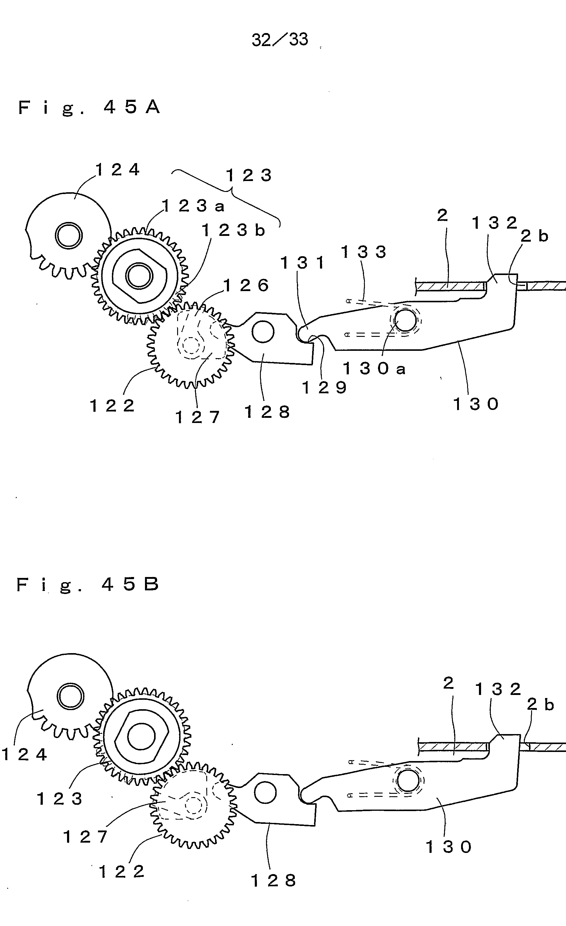
- FIG. 45A is a schematic explanatory view of the rotary drive mechanism shown in FIG. 43 at a reference position.
- FIG. 45B is a schematic explanatory view of the rotation drive mechanism shown in FIG. 43 at an unlocked position.
- FIG. 45C is a schematic explanatory view showing a state where the rotor of the rotary drive mechanism shown in FIG. 43 is rotated to the payout position.
- FIG. 1 shows a medicine dispensing device according to the present embodiment.
- a medicine dispensing apparatus a plurality of cassettes 2 are stored in a storage shelf 1 in a matrix.
- An operation display panel 200 is provided on the front of the storage shelf 1 so that predetermined input and display can be performed.
- a ridge 7 extending in the longitudinal direction is formed on the facing surface of the guide members 30, 31, and the bearing 8 of the slide member 5 rolls on the upper and lower surfaces of the ridge 7.
- a cassette holding portion 9 extending in the longitudinal direction is formed, and when the cassette 2 is mounted on the storage portion 3, the medicine D is pressed by pressing a lid 17 described later. Prevents from rising from set 2.
- the constant load panel 6 is integrated with an encoder 11 on a rotating shaft 10 rotatably provided on the back side of the storage shelf 1.
- the encoder 11 has a disk shape, and a plurality of slits are formed at a predetermined pitch in the outer peripheral portion along the circumferential direction.
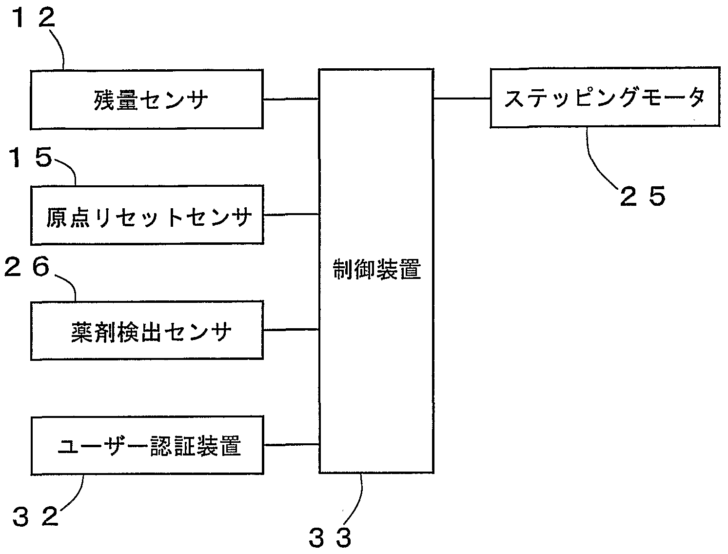
- the origin reset sensor 15 is used to detect the slide member 5 that has moved to the front side when the cassette 2 is not mounted, and to reset the count number by the encoder 11. That is, the dimension (diameter for a sample, width for a medicine box) occupied by one medicine in the longitudinal direction of the cassette 2 and the number of output pulses from the encoder 11 are stored in advance in association with each other. Then, when the cassette 2 is mounted, the quantity of the medicine D is calculated based on the output pulse when the slide member 5 is pushed by the housed medicine D and moves to the rear side.
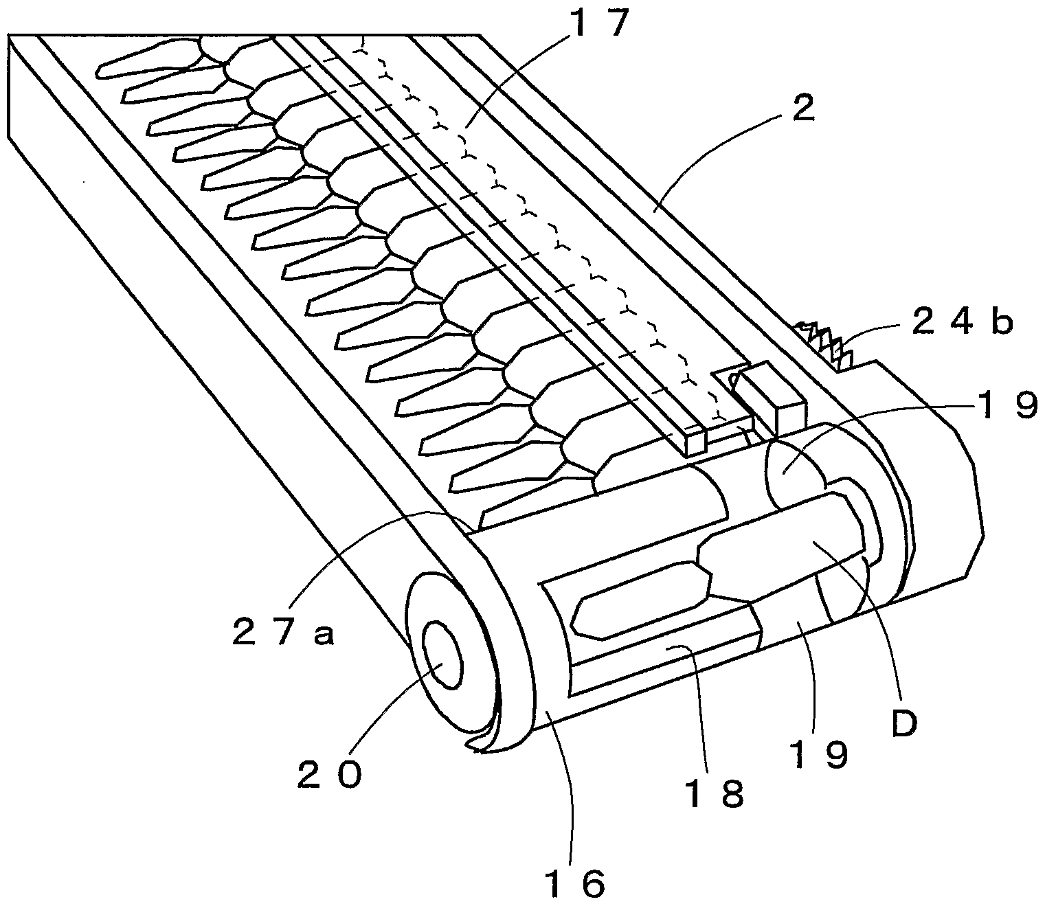
- the rotor 16 has a small rotor for dispensing ampoules, as shown in Fig. 2, and a large rotor for dispensing boxes containing vials, as shown in Figs. 3A and 3B. Etc. These rotors 16 hold drug D as shown in FIG. Holding recess 18 is provided. Notches 19 are formed on both side surfaces of the holding recess 18 so that the medicine D can be easily taken out. At least in the outer peripheral portion on the right end side (may be provided on the outer peripheral portion on the left end side) of the rotor 16, a concave portion 16 a is formed at the holding position, which is continuous with the concave portion 2 a formed in the cassette 2. .
- the second link 24 is driven to rotate forward and reverse based on the driving force of the stepping motor 25 transmitted via the gear 25a.
- the support shaft 24a is provided with magnets (not shown) at three places, and each is detected by the sensor 26, so that the second link 24 is in the standby position (see FIG. 4A), the operation position (see FIG. 4A). It can be stopped at the lock position (see Fig. 6) and the lock position (see Fig. 6).
- the second link 24 is located at the standby position, the rotor 16 via the first link 23, the second gear 22 and the first gear 21 as shown by a dotted line in FIG.
- the holding recess 18 is positioned at a holding position for holding the medicine D in the cassette 2.
- the concave portion 2a formed in the cassette 2 and the concave portion 16a formed in the rotor 16 are located at a continuous position, and a finger can be hooked on this portion to take out the cassette 2 from the storage shelf 1.
- the rotor 16 is indicated by a dotted line in FIG. 5 from the first link 23 via the second gear 22 and the first gear 21 ⁇ . Rotate to unload position Then, the medicine D held in the holding recess 18 can be taken out.
- the second link 24 is rotated to the lock position shown in FIG. 6, the rotor 16 cannot rotate.
- the rotor 16 rotates to the take-out position, whether or not the medicine D is held in the holding recess 18 is detected by a medicine detection sensor (not shown).
- the outer surface of the rotor 16 has a support surface 27 a for supporting the next medicine D when the medicine D is held in the holding recess 18 and rotated.
- a flat surface 27 b for attaching a label printed with is formed.
- the outer shape of the rotor 16 is determined as follows. First, a cylinder provided with a holding recess 18 that can exactly accommodate the medicine D is assumed, and its axis is located at the center position of the medicine D. Then, a shaft portion 20 protrudes from the end face of the rotor 16 on the lower side with respect to the axis of the cylinder and at one end side (the front side of the storage shelf 1). Then, a support surface 27a is formed on an arc centered on the shaft portion 20. Further, when the rotor 16 is located at the holding position, a flat surface 27b is formed continuously from the support surface 27a at a position easily visible from the front side.
- the medicine D can be grasped through the notch 19, and the medicine D can be easily taken out from the holding recess 18. Is possible.
- the stepping motor 25 Is rotated in reverse to rotate the second link 24 from the operating position shown in FIG. 5 to the standby position shown in FIG. 4A (step S5), thereby rotating the rotor 16 to the receiving position. This will give you the next medicine Agent D is retained in HO part 18.
- the shape of the second link 24 is not limited to the above-described substantially V-shape, but may be the substantially I-shape shown in FIGS. 11A and 11B.
- the position indicated by the solid line is the payout position
- the position indicated by the dotted line is the lock position.
- a first gear 21 is provided on the shaft portion 20 of the rotor 16 so as to be combined with the second gear 22.
- these gears 21 and 22 are replaced with those shown in FIG.
- the discontinuous gears 40 and 41 may be provided.
- relief recesses 4Ob and 40c are respectively formed continuously on both sides of the tooth portion 40a.
- a gear 42 is integrated with the interrupted gear 41, and the driving force of the motor 47 is transmitted by sequentially combining the gears 43 to 46.
- the rotor 16 rotates only when the toothed portions 40 &, 41 a of the interrupted gears 40, 41 are engaged with each other.
- the rotor 16 can be reliably positioned at the payout position and the receiving position. Moreover, when the arc portion 41b is located in the escape recesses 40b, 40c, the rotor 16 is in a locked state and cannot be rotated by an external operation.
- the cassettes 2 are arranged horizontally so that they can be stacked in the vertical direction, but they can be arranged vertically or inclined. According to this, the shape of the storage shelf 1 can be appropriately changed according to the arrangement space. For example, when the space for disposing the storage shelves 1 is lower and the force cannot be formed, the cassette 2 may be arranged vertically and the medicine D may be taken out from the upper surface side. It is also possible to arrange the cassette 2 sideways and place the vials and the like with the lid side facing upward.
- FIGS. 13A and 13B show an encoder according to another embodiment.
- a long plate is used instead of a disk. That is, an encoder 51 in which a plurality of slits 50 are formed at predetermined intervals in parallel with a slide shaft 52 extending from the front side to the back side is provided.
- a constant load panel 53 and a position detection sensor 54 are slidably mounted on the slide shaft 52.
- the spring portion 53a of the constant load spring 53 is fixed to the front side, and the medicine D in the cassette 2 is pressed toward the front side by the slide member 55 integrated with the constant load panel 53.
- the position detection sensor 54 detects the slit 50 of the encoder 51, and this detection signal is used for specifying the position of the slide member 55, that is, the quantity of the medicine D in the cassette 2.
- FIG. 14 shows a rotation drive mechanism of the rotor 16 according to another embodiment.
- the rack 61 is rotated by reciprocating the pinion 60 back and forth (left and right in FIG. 14) with a solenoid (not shown) or the like, thereby opposing the urging force of the spring 62.
- the rotor 16 (not shown here) can be positioned at the receiving position and the discharging position via the link 63.
- FIGS. 15A and 15B show a dispensing mechanism according to another embodiment.
- a dispensing plate 71 rotatable around a support shaft 70 is provided in place of the rotor 16.
- the dispensing plate 71 has one end formed with a first locking part 72 for locking the medicine D 1 located at the forefront, and a second locking capable of supporting the next medicine D 2 at the other end.
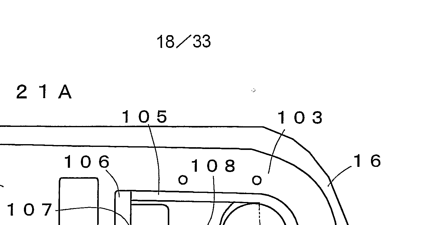
- FIGS. 21A and 21B show an example of a rotation drive mechanism of the rotor 16 according to still another embodiment.
- discs 101 and 102 each having a guide projection 100 formed on a shaft 20 projecting from the center of both end faces of a rotor 16 provided in the cassette 2 are provided with force S, respectively.
- a lock member 103 shown in FIGS. 21A and 21B is provided on the disk 102 side.
- the lock member 103 includes a lock frame 105 urged leftward in the figure by a spring 104.
- One end of the lock frame 105 has a protrusion 107 formed on the inner surface side of the push portion 106 of J, and the protrusion 107 and the groove 108 formed on the side surface of the cassette 2 are formed.
- an engagement groove 109 engaging with and disengaging from the guide projection 100 of the disk 102 is formed at the other end of the lock frame 105.
- the spring 104 and the lock frame 105 are covered by a cover 110 fixed to the cassette 2 except for the pushing portion 106.
- the cover 110 has a slide groove 111 in which the lock frame 105 slides, a first relief recess 112 in which the pushing portion 106 is slidable, and the disk 1 102 described above. And a second escape recessed part 113 that is rotatable.
- the guide projection 100 is disengaged at the center as shown in FIG.
- a drive gear 115 with possible engagement grooves 114 is provided.
- the configuration other than the interrupted gear 40 is the same as that shown in FIG.
- a cut-out portion 116 is formed on one side wall of the housing portion 3, and an engagement groove 114 of the drive gear 115 is exposed.
- the guide projection 100 can be engaged with the engagement groove 114. It works.
- a contact portion 117 with which the pushing portion 106 of the lock frame 105 contacts when the cassette 2 is mounted is formed on the side surface of the storage portion 3.
- FIGS. 23A and 23B show an example of a rotation drive mechanism of the rotor 16 according to still another embodiment.
- This rotation drive mechanism is provided in a casing 80 attached to each storage section 3 of the storage shelf 1, and the driving force of the motor 81 is controlled by the worm gear 82, the worm wheel 83, and the intermediate gear.
- the drive gear 85 is transmitted to the drive gear 85 through the drive gear 84.
- the casing 80 has an upper surface and a side surface that are open, and a side surface that is closed by a cover 86.
- a through hole 80a is formed in one end surface of the casing 80, and a bearing 81a of the motor 81 is fixed to the through hole 80a.
- the worm gear 82 is fixed to a rotating shaft 81 b protruding from a bearing 81 a of the motor 81, and is arranged in the casing 80.
- the worm wheel 83, the intermediate gear 84, and the drive gear 85 are rotatably attached to the cover 86.
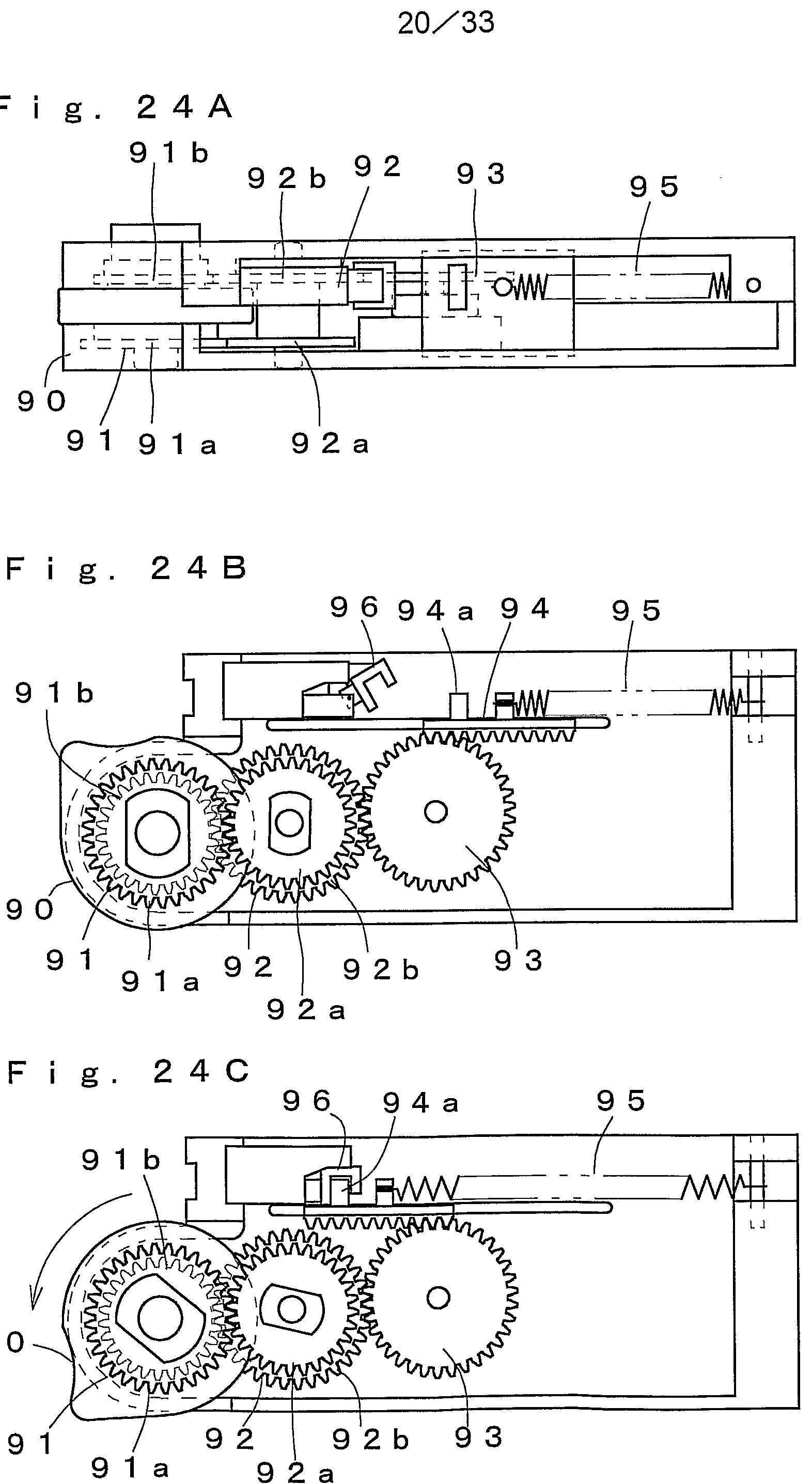
- FIGS. 24A, 24B, and 24C show examples of the rotation drive mechanism of the rotor 16 according to still another embodiment.
- This rotation drive mechanism is provided in each storage section 3 of the storage shelf 1 and includes a rotation force transmission member 90.
- the shaft portion 20 of the rotor 16 provided at one end of the cassette 2 engages with the rotational force transmitting member 90, so that it rotates physically. I have.
- the torque transmitting member 90 includes a first gear.
- the slider 94 is interlocked via the second gear 92 and the third gear 93.
- the first gear 91 integrates the spur gears 9 la and 91 b.
- the second gear 92 is formed by integrating spur gears 92a and 92b, which respectively mesh with the spur gears 91a and 91b of the first gear 91.
- the spur gear 92 a is connected to a gear provided on the rotating shaft of a motor (not shown), and the spur gear 92 b is connected to a third gear 93.
- the slider 94 is urged away from the rotor 16 by the urging force of the spring 95.
- a locking projection 94a is formed on the slider 94, and the latch 96 is locked to the locking projection 94a so that the rotor 16 is positioned at the dispensing position shown in FIG. 24C. Chosen is decided. Further, a damper 97 is provided in the third gear 93, and a sudden rotation caused by the urging force of the spring 95 when the latch 96 is opened is moderated.
- the rotor 16 engages with the rotational force transmitting member 90.
- a motor (not shown) is driven forward and reverse, the rotor 16 is rotated via the rotational force transmitting member 90 to be positioned at the dispensing position or the receiving position, and the medicines D stored in the cassette 2 are dispensed one by one. It is.
- the first gear 91, the second gear 92, and the third gear 93 rotate, and the slider 94 moves to the position shown in FIG. 24C. Then, at this position, the latch 96 is locked to the locking projection 94a.
- FIGS. 43 to 45 show an example of a rotation drive mechanism of the rotor 16 according to still another embodiment.
- This rotation drive mechanism is provided in each storage section 3 of the storage shelf 1.
- the driving force of the motor 120 is changed from the driving gear 122 provided on the rotating shaft 120a to the first intermediate gear 122 and the second intermediate gear 122.
- the transmission to the driven gear 124 provided on the shaft of the rotor 16 via the intermediate gear 123 causes the rotor 16 to rotate.
- the first intermediate gear 122 is provided at one end of a shaft member 125, and a cam 126 is attached to the other end of the shaft member 125.
- the cam 126 has a pressing piece 127, and by rotating about the shaft member 125, pushes one end of the first link 128 with the pressing piece 127. Rotate one link 1 282 around the support shaft 128 a.
- the first link 128 has a connecting recess 129 at one end thereof.
- the connecting recess 129 has a second link 130 provided rotatably about a support shaft 130a.
- a connecting portion 13 1 formed on one end side of the sliding contact is located at the sliding contact position.
- a locking portion 132 is formed. The locking portion 132 can be disengaged from a locking hole 2b formed at the bottom of the cassette 2. ing.
- the second link 130 is urged in the counterclockwise direction in FIG.
- the first intermediate gear 122 is obtained by integrating a first gear 122a composed of a helical gear and a second gear 122b composed of a spur gear.
- the first gear 1 2 2a is combined with the drive gear 1 2 1.
- the second intermediate gear 1 2 3 is composed of a first gear 1 2 3 a composed of a spur gear that is combined with the first gear 1 2 2 a of the first intermediate gear 1 2 2, and a second gear 1 2 3 composed of an interrupted gear. b is integrated.
- the driven gear 1 2 1 is a discontinuous gear similar to the second gear 1 2 3 b of the second intermediate gear 1 2 3, and is interlocked only within a predetermined angle at which the second intermediate gear 1 2 3 rotates. Then, the rotor 16 is rotated. Configuration to rotate rotor 16 using interrupted gear Is the same as that shown in FIG.
- the rotor 16 is rotated via 1 2 1, 1 2 2, 1 2 3 and 1 2 4.
- the forward rotation of the motor 120 rotates the first intermediate gear 122 in the counterclockwise direction, and the driven gear 122 rotates from the position shown in FIG. 45B to the position shown in FIG. 45C. .
- the rotor 16 rotates from the receiving position where the medicine in the cassette 2 can be held in the holding recess 18 to the dispensing position where the medicine is dispensed from the cassette 2.
- the medicine held in the holding recess 18 of the rotor 16 is dispensed.
- the first link 1
- the pressing piece 1 27 of the cam 1 26 comes into contact with one end of the pin 28, and the rotation of the first link 128 is prevented. For this reason, the state where the locking portion 1 32 of the second link 130 is locked in the locking hole 2 b of the cassette 2 is maintained, and the cassette 2 falls off from the storage portion 3 during the medicine dispensing operation. Is reliably prevented.
- the rotor 120 is rotated in the reverse direction and driven to rotate the rotor 16 from the dispensing position to the receiving position.
- FIGS. 25 to 42 show examples of display contents on the operation display panel 200.
- FIG. 25 shows the fingerprint authentication screen in step S2.
- fingerprint authentication is performed, the screen switches to the screen shown in Fig. 26.
- the ⁇ K button is operated, the screen shifts to the various business screens shown in Fig. 27.
- the NG button is operated, the screen returns to the fingerprint authentication screen.
- an anticancer drug management menu that is, a payout business button, a master maintenance button, an inquiry business button, a filling business button, a daily report button, and an end button are displayed.
- the prescription information is read and automatically The list of patient ID, patient name, department, and ward is displayed.
- the screen switches to the payout operation screen shown in Fig. 30, and the information (patient ID, issue date, etc.) of the selected patient and all the prescription contents of the patient are displayed.
- the amount paid out is checked, and addition, deletion, correction, etc. are performed.
- the payout button is operated, the payout process is started in reverse order from the upper row.
- the stock information in the cassette 2 containing the relevant medicine is checked. If there is no stock, the fact is displayed, the data is stored as incomplete information, and the stock check of the next medicine is started. . If there is a stock, the dispensing is started, and the status is displayed in the row of the corresponding medicine on the dispensing business screen so that the progress of the dispensing can be understood (for example, a bar graph indicating what percentage of the dispensing has been completed). ). Rows for which payment processing has been completed are red, rows that are being paid out are green, and rows that have not been paid out are white.
- the manual button is operated on the automatic manual screen, the screen is switched directly to the processing patient list screen, and after inputting data corresponding to each item, the same processing as described above is performed.
- the process is interrupted in the middle of the dispensing process, for example, if a predetermined time has passed since the worker was separated by the weight sensor, or if the device stopped due to an error, etc., the display returns to the initial screen and a new fingerprint authentication is performed. Otherwise, processing cannot be continued. Further, when the processing is desired to be performed later, the processing can be held by operating a hold button (not shown). In this case, as in the case of interruption, the process cannot be resumed without newly performing fingerprint authentication. In the case of interruption, if it is the same operator, the previous process is forcibly restarted (return to the screen at the time of interruption.).
- the screen switches to the inquiry job menu screen shown in Fig. 31, and the prescription history inquiry button, medicine administration search button, medicine consumption button, medicine consumption button by doctor, medicine consumption button by ward, management A usage amount button for each medicine and an end button are displayed.
- the prescription history inquiry button By operating the prescription history inquiry button, the prescription history inquiry screen shown in Fig. 32 can be displayed to inquire the prescription history.
- Drug administration search By operating the button, the drug administration search screen shown in Fig. 33 is displayed, which can be used for investigation when the stock matches.
- the drug usage button By operating the drug usage button, the drug usage screen shown in Fig. 34 is displayed, and a list of drug usage is displayed according to the date of administration. Can be done.
- the physician-specific drug usage button By operating the physician-specific drug usage button, the physician-specific drug usage screen shown in Fig.
- the ward-specific drug usage buttons By operating the ward-specific drug usage buttons, the ward-specific drug usage shown in Fig. 37 can be displayed, and the ward-level drug usage can be confirmed.
- the usage amount for each controlled medicine button By operating the usage amount for each controlled medicine button, the usage amount for each managed drug is displayed as shown in Fig. 38, and it is possible to investigate the medicine for which management of psychotropic drugs, etc., is required for each medicine. .
- the screen switches to the master maintenance screen shown in Fig. 39, and the patient master button, drug master button, etc. are displayed.
- the medicine master button is operated, the screen switches to the medicine master screen shown in Fig. 40, and a list of medicine information can be displayed.
- the reference stock indicates the maximum amount of medicines that can be stocked, and the appropriate stock indicates the minimum stock that needs to be replenished.
- the screen switches to the daily report menu screen shown in Fig. 41, and the payout daily report button and the filling daily report button are displayed.
- the screen switches to the filling 0 report screen shown in Fig. 42, and by inputting the S with the desired output, the filling status of the medicine can be displayed in a list. This makes it possible to check for filling errors and the like.
Description
Claims


Priority Applications (7)
| Application Number | Priority Date | Filing Date | Title |
|---|---|---|---|
| CA002495526A CA2495526A1 (en) | 2002-08-05 | 2003-08-05 | Drug dispenser |
| JP2004525833A JP4473728B2 (ja) | 2002-08-05 | 2003-08-05 | 薬剤払出装置 |
| US10/523,823 US7434704B2 (en) | 2002-08-05 | 2003-08-05 | Medicine feeder |
| EP03766730A EP1541114A4 (en) | 2002-08-05 | 2003-08-05 | DRUGS DONORS |
| CN038119617A CN1655751B (zh) | 2002-08-05 | 2003-08-05 | 药剂支出装置 |
| KR1020107014504A KR101052611B1 (ko) | 2002-08-05 | 2003-08-05 | 약제불출장치 |
| NO20051163A NO20051163L (no) | 2002-08-05 | 2005-03-04 | Medisinbeholder |
Applications Claiming Priority (4)
| Application Number | Priority Date | Filing Date | Title |
|---|---|---|---|
| JP2002-227071 | 2002-08-05 | ||
| JP2002227071 | 2002-08-05 | ||
| JP2002305166 | 2002-10-18 | ||
| JP2002-305166 | 2002-10-18 |
Publications (1)
| Publication Number | Publication Date |
|---|---|
| WO2004012647A1 true WO2004012647A1 (ja) | 2004-02-12 |
Family
ID=31497630
Family Applications (1)
| Application Number | Title | Priority Date | Filing Date |
|---|---|---|---|
| PCT/JP2003/009902 WO2004012647A1 (ja) | 2002-08-05 | 2003-08-05 | 薬剤払出装置 |
Country Status (9)
| Country | Link |
|---|---|
| US (1) | US7434704B2 (ja) |
| EP (3) | EP2034459A3 (ja) |
| JP (2) | JP4473728B2 (ja) |
| KR (2) | KR101003548B1 (ja) |
| CN (1) | CN1655751B (ja) |
| CA (1) | CA2495526A1 (ja) |
| NO (1) | NO20051163L (ja) |
| TW (1) | TWI290898B (ja) |
| WO (1) | WO2004012647A1 (ja) |
Cited By (6)
| Publication number | Priority date | Publication date | Assignee | Title |
|---|---|---|---|---|
| CN100430038C (zh) * | 2003-09-26 | 2008-11-05 | 株式会社汤山制作所 | 药品发放装置 |
| JP2010017458A (ja) * | 2008-07-14 | 2010-01-28 | Yuyama Manufacturing Co Ltd | 複連アンプル払出装置 |
| WO2010032475A1 (ja) * | 2008-09-19 | 2010-03-25 | 株式会社湯山製作所 | 薬剤払出装置 |
| US7721914B2 (en) | 2004-09-13 | 2010-05-25 | Michael Handfield | Container for dispensing medicaments having a compressible medium therein |
| US8146753B2 (en) * | 2006-03-27 | 2012-04-03 | Yuyama Mfg. Co., Ltd. | Medicine cart |
| JP2016105817A (ja) * | 2008-09-19 | 2016-06-16 | 株式会社湯山製作所 | 薬剤払出装置 |
Families Citing this family (35)
| Publication number | Priority date | Publication date | Assignee | Title |
|---|---|---|---|---|
| JP4468729B2 (ja) * | 2003-10-16 | 2010-05-26 | 株式会社湯山製作所 | 薬剤払出装置 |
| KR101182088B1 (ko) * | 2004-05-19 | 2012-09-11 | 가부시키가이샤 유야마 세이사쿠쇼 | 약품 불출 장치 |
| WO2005114320A1 (ja) * | 2004-05-21 | 2005-12-01 | Figla Co., Ltd. | 浴室用プロジェクターシステム及びプロジェクター投映装置 |
| JP4520814B2 (ja) * | 2004-10-15 | 2010-08-11 | 株式会社湯山製作所 | 薬品払出装置 |
| US8468777B2 (en) * | 2005-02-16 | 2013-06-25 | Yuyama Mfg. Co., Ltd. | Tablet filling device |
| JP4629476B2 (ja) * | 2005-03-30 | 2011-02-09 | 株式会社湯山製作所 | 薬品充填業務支援システム |
| JP5044906B2 (ja) * | 2005-08-25 | 2012-10-10 | 株式会社湯山製作所 | 薬剤払出装置 |
| US8271128B1 (en) | 2008-07-30 | 2012-09-18 | Kirby Lester, Llc | Pharmacy workflow management system including plural counters |
| US8588966B2 (en) | 2009-01-09 | 2013-11-19 | Automed Technologies, Inc. | Cabinet system |
| US8744621B2 (en) | 2009-01-09 | 2014-06-03 | Automed Technologies, Inc. | Medical cabinet access belt optimization system |
| US9121197B2 (en) | 2009-01-09 | 2015-09-01 | Automed Technologies, Inc. | Cabinet system with improved drawer security |
| US8103379B2 (en) * | 2009-01-09 | 2012-01-24 | Automed Technologies, Inc. | Medication cabinetry |
| KR101776347B1 (ko) * | 2009-08-12 | 2017-09-07 | 가부시키가이샤 유야마 세이사쿠쇼 | 약제 불출 장치 |
| US8746908B2 (en) | 2010-01-27 | 2014-06-10 | Automed Technologies, Inc. | Medical supply cabinet with lighting features |
| JP2012018560A (ja) * | 2010-07-08 | 2012-01-26 | Panasonic Corp | 薬剤取揃支援システム |
| KR101293099B1 (ko) * | 2011-03-15 | 2013-08-12 | (주)제이브이엠 | 약품공급장치 |
| CN102602639B (zh) * | 2012-03-15 | 2014-04-16 | 江苏迅捷装具科技有限公司 | 基于盒装物品最大侧面相接触排列的储存配发装置及方法 |
| CN103387063B (zh) * | 2012-05-07 | 2015-04-29 | 郝荣华 | 医疗针剂的调配包装装置 |
| US9150119B2 (en) | 2013-03-15 | 2015-10-06 | Aesynt Incorporated | Apparatuses, systems, and methods for anticipating and delivering medications from a central pharmacy to a patient using a track based transport system |
| US9511945B2 (en) | 2012-10-12 | 2016-12-06 | Aesynt Incorporated | Apparatuses, systems, and methods for transporting medications from a central pharmacy to a patient in a healthcare facility |
| JP5673779B2 (ja) * | 2012-11-20 | 2015-02-18 | キヤノンマーケティングジャパン株式会社 | 分包システム、錠剤供給装置及びその制御方法、プログラム |
| WO2014112221A1 (ja) * | 2013-01-18 | 2014-07-24 | 株式会社湯山製作所 | 薬品払出装置、薬品払出方法、薬品払出プログラム、記録媒体 |
| KR102049273B1 (ko) * | 2013-02-13 | 2020-01-08 | (주)제이브이엠 | 약제 불출 유닛 및 이를 포함하는 약제 불출 장치 |
| TWI582026B (zh) * | 2013-04-03 | 2017-05-11 | Jung Hua Shao | Acupuncture administration |
| JP6159135B2 (ja) * | 2013-04-26 | 2017-07-05 | パナソニックヘルスケアホールディングス株式会社 | 薬剤収納カセットおよびこれを備えた薬剤払出装置 |
| KR102114901B1 (ko) * | 2013-10-02 | 2020-05-25 | (주)제이브이엠 | 약제 불출 장치 |
| US9977871B2 (en) | 2014-01-14 | 2018-05-22 | Capsa Solutions Llc | Cassette control including presence sensing and verification |
| JP6143700B2 (ja) * | 2014-03-31 | 2017-06-07 | 東芝テック株式会社 | 薬剤登録装置およびプログラム |
| CN105982446A (zh) * | 2015-01-29 | 2016-10-05 | Hmh株式会社 | 药品匣以及包括药品匣的药品柜 |
| CN106144378B (zh) * | 2016-06-29 | 2018-09-14 | 苏州信亨自动化科技有限公司 | 瓶装药剂自动发药装置 |
| CN107497713B (zh) * | 2017-08-29 | 2024-02-02 | 信远德怡医疗科技(北京)有限公司 | 一种药瓶自动分拣装置 |
| US10517799B2 (en) * | 2017-08-31 | 2019-12-31 | Omnicell, Inc. | Unit dose dispensing mechanisms |
| CN112773709A (zh) * | 2021-02-01 | 2021-05-11 | 天津山岩科技有限公司 | 一种应急药盒 |
| CN113213033B (zh) * | 2021-04-08 | 2023-03-28 | 深圳市瑞意博科技股份有限公司 | 一种药物补取控制方法、装置、设备及存储介质 |
| CN115137594B (zh) * | 2022-07-05 | 2023-06-16 | 东莞职业技术学院 | 一种社区医疗卫生护理用移动配药装置 |
Citations (5)
| Publication number | Priority date | Publication date | Assignee | Title |
|---|---|---|---|---|
| JPS62502870A (ja) * | 1985-04-11 | 1987-11-19 | アテン,エドワ−ド・エム | 制御された分配装置 |
| JPH05229660A (ja) * | 1992-02-17 | 1993-09-07 | Shoji Yuyama | 薬液用容器の貯留供給装置 |
| JP2000072204A (ja) * | 1998-09-01 | 2000-03-07 | Matsushita Electric Ind Co Ltd | 注射薬自動払出装置 |
| US6112502A (en) * | 1998-02-10 | 2000-09-05 | Diebold, Incorporated | Restocking method for medical item dispensing system |
| JP3082647U (ja) * | 2001-05-29 | 2001-12-21 | サンコースプリング株式会社 | 載置物品押出具 |
Family Cites Families (25)
| Publication number | Priority date | Publication date | Assignee | Title |
|---|---|---|---|---|
| US4111332A (en) * | 1972-09-13 | 1978-09-05 | Hurst Kerney J | Article counting device |
| US4018358A (en) * | 1975-09-18 | 1977-04-19 | Pharmaceutical Innovators, Ltd. | Cassette pill storing, dispensing and counting machine |
| US4697721A (en) * | 1985-06-24 | 1987-10-06 | Pharmaceutical Innovators Ltd. | Pill storage and dispensing cassette |
| JP2693431B2 (ja) | 1987-03-17 | 1997-12-24 | アルプス電気株式会社 | コンビネーシヨン磁気ヘツドおよびその製造方法 |
| JPH0228406A (ja) | 1988-07-19 | 1990-01-30 | Tokyo Shokai:Kk | オーダによる注射アンプル自動供給装置及ぎその供給方法 |
| JPH04278933A (ja) * | 1991-03-07 | 1992-10-05 | Canon Inc | カメラ |
| US5337919A (en) * | 1993-02-11 | 1994-08-16 | Dispensing Technologies, Inc. | Automatic dispensing system for prescriptions and the like |
| US5431299A (en) * | 1994-01-26 | 1995-07-11 | Andrew E. Brewer | Medication dispensing and storing system with dispensing modules |
| JP2804884B2 (ja) * | 1994-03-28 | 1998-09-30 | 正二 湯山 | 薬液容器の収納ケース及びそのケースを用いた容器貯留装置 |
| JP3170579B2 (ja) | 1994-04-18 | 2001-05-28 | 株式会社エム・シー・エー | アンプル払い出し装置 |
| US5797515A (en) | 1995-10-18 | 1998-08-25 | Adds, Inc. | Method for controlling a drug dispensing system |
| US5860563A (en) * | 1997-06-23 | 1999-01-19 | Scriptpro, Llc | Medicine vial dispenser |
| JP2987124B2 (ja) * | 1997-06-23 | 1999-12-06 | 正二 湯山 | 薬液入り容器供給装置 |
| US6170230B1 (en) * | 1998-12-04 | 2001-01-09 | Automed Technologies, Inc. | Medication collecting system |
| JP4163806B2 (ja) * | 1999-03-04 | 2008-10-08 | 株式会社湯山製作所 | 定量払出し用のアンプル収納容器およびアンプル定量供給装置 |
| JP2000255717A (ja) * | 1999-03-10 | 2000-09-19 | Matsushita Electric Ind Co Ltd | 製品の残数管理方法および製品取出装置 |
| US6189727B1 (en) * | 1999-03-24 | 2001-02-20 | S&S X-Ray Products, Inc. | Pharmaceutical dispensing arrangement |
| US6216910B1 (en) * | 1999-04-28 | 2001-04-17 | Allen Numerick | Automatic article dispenser |
| US6370841B1 (en) * | 1999-12-03 | 2002-04-16 | Automed Technologies, Inc. | Automated method for dispensing bulk medications with a machine-readable code |
| JP4462689B2 (ja) * | 2000-01-18 | 2010-05-12 | 株式会社トーショー | 薬品収納装置 |
| WO2002091987A2 (en) * | 2001-05-15 | 2002-11-21 | E-Medication Aps | A medicine dispenser |
| JP4467850B2 (ja) | 2001-09-14 | 2010-05-26 | パナソニック株式会社 | 注射薬自動払出装置 |
| JP4436581B2 (ja) | 2001-09-14 | 2010-03-24 | パナソニック株式会社 | 注射薬自動払出装置 |
| US7228198B2 (en) * | 2002-08-09 | 2007-06-05 | Mckesson Automation Systems, Inc. | Prescription filling apparatus implementing a pick and place method |
| TWI295573B (en) * | 2002-10-18 | 2008-04-11 | Yuyama Mfg Co Ltd | Feeding device of drug |
-
2003
- 2003-08-04 TW TW092121270A patent/TWI290898B/zh not_active IP Right Cessation
- 2003-08-05 CN CN038119617A patent/CN1655751B/zh not_active Expired - Fee Related
- 2003-08-05 CA CA002495526A patent/CA2495526A1/en not_active Abandoned
- 2003-08-05 WO PCT/JP2003/009902 patent/WO2004012647A1/ja active Application Filing
- 2003-08-05 KR KR1020047019898A patent/KR101003548B1/ko not_active IP Right Cessation
- 2003-08-05 JP JP2004525833A patent/JP4473728B2/ja not_active Expired - Fee Related
- 2003-08-05 EP EP08169629A patent/EP2034459A3/en not_active Withdrawn
- 2003-08-05 EP EP03766730A patent/EP1541114A4/en not_active Withdrawn
- 2003-08-05 EP EP10173022A patent/EP2251842A1/en not_active Withdrawn
- 2003-08-05 KR KR1020107014504A patent/KR101052611B1/ko active IP Right Grant
- 2003-08-05 US US10/523,823 patent/US7434704B2/en not_active Expired - Fee Related
-
2005
- 2005-03-04 NO NO20051163A patent/NO20051163L/no not_active Application Discontinuation
-
2009
- 2009-08-17 JP JP2009188533A patent/JP5051194B2/ja not_active Expired - Fee Related
Patent Citations (5)
| Publication number | Priority date | Publication date | Assignee | Title |
|---|---|---|---|---|
| JPS62502870A (ja) * | 1985-04-11 | 1987-11-19 | アテン,エドワ−ド・エム | 制御された分配装置 |
| JPH05229660A (ja) * | 1992-02-17 | 1993-09-07 | Shoji Yuyama | 薬液用容器の貯留供給装置 |
| US6112502A (en) * | 1998-02-10 | 2000-09-05 | Diebold, Incorporated | Restocking method for medical item dispensing system |
| JP2000072204A (ja) * | 1998-09-01 | 2000-03-07 | Matsushita Electric Ind Co Ltd | 注射薬自動払出装置 |
| JP3082647U (ja) * | 2001-05-29 | 2001-12-21 | サンコースプリング株式会社 | 載置物品押出具 |
Non-Patent Citations (1)
| Title |
|---|
| See also references of EP1541114A4 * |
Cited By (21)
| Publication number | Priority date | Publication date | Assignee | Title |
|---|---|---|---|---|
| CN100430038C (zh) * | 2003-09-26 | 2008-11-05 | 株式会社汤山制作所 | 药品发放装置 |
| US7886931B2 (en) | 2004-09-13 | 2011-02-15 | Michael Handfield | Medicament container system and method |
| US7949426B2 (en) | 2004-09-13 | 2011-05-24 | Michael Handfield | Medicaments container with display component |
| US7721914B2 (en) | 2004-09-13 | 2010-05-25 | Michael Handfield | Container for dispensing medicaments having a compressible medium therein |
| US7735683B2 (en) | 2004-09-13 | 2010-06-15 | Michael Handfield | Smart tray for dispensing medicaments |
| US7735681B2 (en) | 2004-09-13 | 2010-06-15 | Handfield Michael | Medicament container locking system and method |
| US7751933B2 (en) | 2004-09-13 | 2010-07-06 | Michael Handfield | Smart tray for dispensing medicaments |
| US7860603B2 (en) | 2004-09-13 | 2010-12-28 | Michael Handfield | Medicaments container with medicament authentication mechanism |
| US7908030B2 (en) | 2004-09-13 | 2011-03-15 | Michael Handfield | Smart tray for dispensing medicaments |
| US8112175B2 (en) | 2004-09-13 | 2012-02-07 | Michael Handfield | Methods and apparatus for medicament tracking |
| US8027748B2 (en) | 2004-09-13 | 2011-09-27 | Michael Handfield | Medicament container |
| US7844362B2 (en) | 2004-09-13 | 2010-11-30 | Michael Handfield | Method of intelligently dispensing medicaments |
| US7909207B2 (en) | 2004-09-13 | 2011-03-22 | Michael Handfield | Smart tray for dispensing medicaments |
| US7917246B2 (en) | 2004-09-13 | 2011-03-29 | Michael Handfield | Lockable medicament dispensing apparatus with authentication mechanism |
| US7996105B2 (en) | 2004-09-13 | 2011-08-09 | Michael Handfield | Medicament dispensing authorization |
| US8146753B2 (en) * | 2006-03-27 | 2012-04-03 | Yuyama Mfg. Co., Ltd. | Medicine cart |
| JP2010017458A (ja) * | 2008-07-14 | 2010-01-28 | Yuyama Manufacturing Co Ltd | 複連アンプル払出装置 |
| WO2010032475A1 (ja) * | 2008-09-19 | 2010-03-25 | 株式会社湯山製作所 | 薬剤払出装置 |
| JP2016105817A (ja) * | 2008-09-19 | 2016-06-16 | 株式会社湯山製作所 | 薬剤払出装置 |
| US8991138B2 (en) | 2008-09-19 | 2015-03-31 | Yuyama Mfg. Co., Ltd. | Medicine dispensing device |
| JP2010201152A (ja) * | 2008-09-19 | 2010-09-16 | Yuyama Manufacturing Co Ltd | 薬剤払出装置 |
Also Published As
| Publication number | Publication date |
|---|---|
| KR20100087405A (ko) | 2010-08-04 |
| CN1655751B (zh) | 2012-10-10 |
| EP2034459A3 (en) | 2009-05-20 |
| EP1541114A1 (en) | 2005-06-15 |
| EP2251842A1 (en) | 2010-11-17 |
| JP5051194B2 (ja) | 2012-10-17 |
| TWI290898B (en) | 2007-12-11 |
| US7434704B2 (en) | 2008-10-14 |
| NO20051163L (no) | 2005-03-30 |
| KR101003548B1 (ko) | 2010-12-30 |
| EP1541114A4 (en) | 2007-11-07 |
| JP2010000369A (ja) | 2010-01-07 |
| JPWO2004012647A1 (ja) | 2006-09-21 |
| CA2495526A1 (en) | 2004-02-12 |
| JP4473728B2 (ja) | 2010-06-02 |
| EP2034459A2 (en) | 2009-03-11 |
| KR101052611B1 (ko) | 2011-07-29 |
| KR20050048543A (ko) | 2005-05-24 |
| TW200403174A (en) | 2004-03-01 |
| US20060113314A1 (en) | 2006-06-01 |
| CN1655751A (zh) | 2005-08-17 |
Similar Documents
| Publication | Publication Date | Title |
|---|---|---|
| WO2004012647A1 (ja) | 薬剤払出装置 | |
| DK2367519T3 (en) | Dosing and dispensing device | |
| US6785589B2 (en) | Dispensing cabinet with unit dose dispensing drawer | |
| US8020725B2 (en) | Medicine dispensing apparatus | |
| US20040129716A1 (en) | Portable medication dispenser | |
| CA2701396A1 (en) | Medication dispensing and control unit | |
| WO2000018646A1 (en) | Drug feeder | |
| US20050256830A1 (en) | Systems and methods for storing and dispensing medication | |
| US20030222548A1 (en) | Storage device for health care facility | |
| US6019249A (en) | Apparatus for dispensing medical items | |
| WO2011049167A1 (ja) | 薬剤払出装置 | |
| WO2006046642A1 (ja) | 調剤支援装置及び調剤支援方法 | |
| US6902083B1 (en) | Method for dispensing medical items | |
| WO2000018643A1 (en) | Drug feeder | |
| US6776306B1 (en) | Apparatus for dispensing medical items | |
| US7048142B1 (en) | Apparatus for dispensing medical items | |
| JP2002345928A (ja) | 薬剤管理システム及び薬剤管理装置 | |
| JP2003135565A (ja) | 薬品保管キャビネット | |
| WO2004111955A1 (ja) | 物品取出装置 | |
| JP2011078598A (ja) | 自動薬剤供給装置 | |
| JP7368786B2 (ja) | 錠剤カセットのロック解除システム | |
| JP6267058B2 (ja) | 薬品払出ユニットと、それを備えた薬品払出装置および薬品払出方法 | |
| KR102652743B1 (ko) | 약제 불출 장치 |
Legal Events
| Date | Code | Title | Description |
|---|---|---|---|
| AK | Designated states |
Kind code of ref document: A1 Designated state(s): CA CN JP KR NO US |
|
| AL | Designated countries for regional patents |
Kind code of ref document: A1 Designated state(s): AT BE BG CH CY CZ DE DK EE ES FI FR GB GR HU IE IT LU MC NL PT RO SE SI SK TR |
|
| 121 | Ep: the epo has been informed by wipo that ep was designated in this application | ||
| WWE | Wipo information: entry into national phase |
Ref document number: 2004525833 Country of ref document: JP |
|
| WWE | Wipo information: entry into national phase |
Ref document number: 20038119617 Country of ref document: CN |
|
| WWE | Wipo information: entry into national phase |
Ref document number: 1020047019898 Country of ref document: KR |
|
| ENP | Entry into the national phase |
Ref document number: 2495526 Country of ref document: CA |
|
| WWE | Wipo information: entry into national phase |
Ref document number: 2003766730 Country of ref document: EP |
|
| WWP | Wipo information: published in national office |
Ref document number: 1020047019898 Country of ref document: KR |
|
| WWP | Wipo information: published in national office |
Ref document number: 2003766730 Country of ref document: EP |
|
| ENP | Entry into the national phase |
Ref document number: 2006113314 Country of ref document: US Kind code of ref document: A1 |
|
| WWE | Wipo information: entry into national phase |
Ref document number: 10523823 Country of ref document: US |
|
| WWP | Wipo information: published in national office |
Ref document number: 10523823 Country of ref document: US |