WO2005110258A1 - Spine insert - Google Patents
Spine insert Download PDFInfo
- Publication number
- WO2005110258A1 WO2005110258A1 PCT/KR2005/001451 KR2005001451W WO2005110258A1 WO 2005110258 A1 WO2005110258 A1 WO 2005110258A1 KR 2005001451 W KR2005001451 W KR 2005001451W WO 2005110258 A1 WO2005110258 A1 WO 2005110258A1
- Authority
- WO
- WIPO (PCT)
- Prior art keywords
- spacer
- spinous processes
- band
- intervertebral implant
- notch
- Prior art date
Links
Classifications
-
- A—HUMAN NECESSITIES
- A61—MEDICAL OR VETERINARY SCIENCE; HYGIENE
- A61B—DIAGNOSIS; SURGERY; IDENTIFICATION
- A61B17/00—Surgical instruments, devices or methods, e.g. tourniquets
- A61B17/56—Surgical instruments or methods for treatment of bones or joints; Devices specially adapted therefor
- A61B17/58—Surgical instruments or methods for treatment of bones or joints; Devices specially adapted therefor for osteosynthesis, e.g. bone plates, screws, setting implements or the like
- A61B17/68—Internal fixation devices, including fasteners and spinal fixators, even if a part thereof projects from the skin
- A61B17/70—Spinal positioners or stabilisers ; Bone stabilisers comprising fluid filler in an implant
- A61B17/7053—Spinal positioners or stabilisers ; Bone stabilisers comprising fluid filler in an implant with parts attached to bones or to each other by flexible wires, straps, sutures or cables
-
- A—HUMAN NECESSITIES
- A61—MEDICAL OR VETERINARY SCIENCE; HYGIENE
- A61B—DIAGNOSIS; SURGERY; IDENTIFICATION
- A61B17/00—Surgical instruments, devices or methods, e.g. tourniquets
- A61B17/56—Surgical instruments or methods for treatment of bones or joints; Devices specially adapted therefor
- A61B17/58—Surgical instruments or methods for treatment of bones or joints; Devices specially adapted therefor for osteosynthesis, e.g. bone plates, screws, setting implements or the like
- A61B17/68—Internal fixation devices, including fasteners and spinal fixators, even if a part thereof projects from the skin
- A61B17/70—Spinal positioners or stabilisers ; Bone stabilisers comprising fluid filler in an implant
- A61B17/7062—Devices acting on, attached to, or simulating the effect of, vertebral processes, vertebral facets or ribs ; Tools for such devices
Definitions
- the present invention relates to an intervertebral implant, and more particularly, to an intervertebral implant which is fixedly placed between spinous processes of adjacent vertebrae to maintain a predetermined space between the spinous processes and to prevent a relative displacement between adjacent superior and inferior facets.
- FIG. 1 is a lateral view of a typical human spinal column.
- a plurality of spinous processes 3 are positioned at the back of the human body and a plurality of v.ertebral bodies 8 are positioned on the opposite side.
- a vertebral nerve 1 is located in a space between the spinous processes 3 and the vertebral bodies 8.
- Interspinous ligaments 7 and ligamentum flava 6 are positioned between the spinous processes 3.
- Supraspinous ligaments 5 and a skin 20 run along the posterior surfaces of the spinous processes 3.
- the human spinal column undergoes a retrogressive change.
- the space between the spinous processes 3 decreases (as represented by a dotted line (A) )
- the ligamentum flava 6 thicken while losing their resilience and protrude anteriorly (as represented by a dotted line (B) ) . Therefore, the spinous processes 3 or the ligamentum flava 6 compress the vertebral nerve 1 or the nerve processes (not shown) connected to the vertebral nerve 1, which is called "spinal stenosis.”
- Medication, physical therapy, and surgery have been utilized in the treatment of spinal stenosis. Surgical treatment is done when spinal stenosis cannot be managed through non-surgical treatments.
- an intervertebral implant includes a spacer 2 having two opposing notches suitable for receiving two spinous processes 3a and 3b of two vertebrae to be inserted between the two spinous processes 3a and 3b.
- one of the two opposing notches is defined by two upper flanges 11a and 12a with inner walls and the other notch is defined by two lower flanges lib and 12b with inner walls.
- the intervertebral implant also includes ties 13a and 13b for securing the spacer 2 to the two spinous processes 3a and 3b. These ties 13a and 13b surround surface portions of the spinous processes 3a and 3b.
- a transversal member which does not permit x-rays to pass therethrough may be inserted into the spacer 2.
- the transversal member is sufficiently thin so that x-ray observation is not disturbed, and it is encased in a central housing 14.
- FIG. 1 is a lateral view of a typical human spinal column.
- FIG. 2 is a view illustrating a conventional intervertebral implant.
- FIG. 3 is a perspective view of a spacer according to an embodiment of the present invention.
- FIG. 4 is a front view of a spacer according to an embodiment of the present invention.
- FIG. 5 is a right side view of a spacer according to an embodiment of the present invention.
- FIG. 6 is a perspective view of a strap according to the present invention.
- FIGS. 7 and 8 are views illustrating the insertion of a spacer into the human body.
- FIG. 9 is a diagrammatic view of a spinal column showing a spacer inserted between adjacent spinous processes.
- FIGS. 1 is a lateral view of a typical human spinal column.
- FIG. 2 is a view illustrating a conventional intervertebral implant.
- FIG. 3 is a perspective view of a spacer according to an embodiment of the present invention.
- FIG. 10 through 13 are sequential views illustrating the installing of a spacer with a strap according to a first embodiment of the present invention.
- FIG. 14 is a view illustrating a spacer installed with a strap according to a second embodiment of the present invention.
- FIGS. 15 and 16 are sequential views illustrating the installing of the spacer with the strap according to the second embodiment of the present invention.
- FIG. 17 is a diagrammatic lateral view of a spinal column showing a spacer inserted between adjacent spinous processes according to an embodiment of the present invention.
- FIG. 18 is a diagrammatic view illustrating a lever system in the human body.
- FIG. 19 is a diagrammatic view of a human spinal column illustrating normal articulation of facet joints.
- FIG. 20 is a diagrammatic view showing the state of a spinal column after a spacer is inserted thereinto according to a conventional technique.
- FIG. 21 is a diagrammatic view showing the state of a spinal column after a spacer is inserted thereinto according to the present invention.
- FIG. 22 is a graph illustrating the profile slope of a first notch of an intervertebral implant according to an embodiment of the present invention plotted in the x-y plane.
- FIG. 23 is a histogram illustrating the distribution of lower surface slope measurements of the third spinous process.
- FIG. 24 is a histogram illustrating the distribution of lower surface slope measurements of the fourth spinous process .
- FIG. 25 is a flow diagram illustrating a method of manufacturing a first notch of an intervertebral implant according to an embodiment of the present invention.
- FIG. 26 is a graph illustrating the lower surface slope of the third spinous process plotted in the x-y plane.
- FIG. 27 is a graph illustrating the lower surface slope of the fourth spinous process plotted in the x-y plane.
- FIG. 28 is a graph illustrating the mean lower surface slope of the third and fourth spinous processes plotted in the x-y plane .
- FIG. 29 is a schematic block diagram illustrating a spinal image clustering system according to an embodiment of the present invention.
- FIG. 30 is a flow diagram illustrating a spinal image clustering according to an embodiment of the present invention.
- FIG. 31 is a detailed flow diagram of a preparing operation S210 of the spinal image clustering of FIG. 30.
- FIG. 32 shows a spinal sectional image of 256 gray levels with a selected volume of interest (VOI) .
- FIGS. 33 and 34 are respectively a sectional image of 256 gray levels for a selected VOI and a binarized sectional image of the 256 gray-levels image by image binarization.
- FIG. 35 is a detailed flow diagram of a clustering operation S220 of the spinal image clustering of FIG. 30.
- FIG. 36 is a detailed flow diagram of a representative image matching operation S270 of the spinal image clustering of FIG. 30.
- FIG. 37 is an exemplary view of a representative image matching operation according to an embodiment of the present invention.
- FIG. 38 through 40 are sectional views illustrating assignment of gray-level values to a case image and a region of interest (ROI) of a matching template according to an embodiment of the present invention.
- FIG. 41 is a perspective view illustrating a variable space that can be scanned by a matching template in a case according to an embodiment of the present invention.
- FIG. 42 is a perspective view illustrating a spacer according to another embodiment of the present invention.
- FIG. 43 is a diagrammatic lateral view of a spinal column illustrating the placement of the spacer of FIG. 42 between adjacent spinous processes.
- FIG. 44 is a sectional view of the spacer of FIG. 43 fitted with a band.
- FIG. 45 is a perspective view illustrating a spacer according to still another embodiment of the present invention.
- FIG. 41 is a perspective view illustrating a variable space that can be scanned by a matching template in a case according to an embodiment of the present invention.
- FIG. 42 is a perspective view illustrating a spacer according to
- FIG. 46 is a left side view of the spacer of FIG. 45.
- FIG. 47 is a diagrammatic lateral view of a spinal column illustrating the placement of the spacer of FIG. 45 between adjacent spinous processes.
- DETAILED DESCRIPTION OF THE INVENTION Technical Problem In the conventional intervertebral implant shown in FIG. 2, in addition to the interspinous ligament between the spinous processes 3a and 3b, in which the spacer 2 is inserted, a higher interspinous ligament and a lower interspinous ligament are also removed and then the spinous processes 3a and 3b are surrounded by the ties 13a and 13b. As such, since unaffected ligaments are also removed, lengthy surgery and recovery time is required.
- the tie 13a surrounds the upper flanges 11a and 12a of the spacer 2 and the spinous process 3a and the tie 13b surrounds the lower flanges lib and 12b of the spacer 2 and the spinous process 3b, the horizontally-directed bearing power for the spacer 2 low.
- the spacer 2 may be dislocated in a horizontal direction.
- the present invention provides an intervertebral implant that maintains a predetermined space between spinous processes of two vertebrae and prevents a relative displacement between the two vertebrae.
- the present invention also provides an intervertebral implant that can be placed between spinous processes after removing only an affected interspinous ligament.
- an intervertebral implant including a spacer having two opposing notches receiving two adjacent spinous processes and a band securing the two spinous processes and the spacer, the spacer including a through-hole bored through sides of the spacer to allow the band to pass therethrough and depressions curved inwardly from outsides of the spacer to facilitate fastening of the band passed through the through-hole, and the band binding the two spinous processes and the spacer in a figure 8 while passing through the through-hole to secure the two spinous processes and the spacer.
- an intervertebral implant including a spacer having two opposing notches and receiving two adjacent spinous processes, an elastic folding portion connecting the two opposing notches and producing an elastic restoring force to counter an external force generated from the two spinous processes, two through-holes formed respectively on the two opposing notches, and a band binding the spacer and the two spinous processes by passing through the two through-holes.
- an intervertebral implant including an upper body having a first notch, a lower body having a second notch opposite the first notch, a cylindrical receiver formed on a lower portion of the upper body, and an insertion member formed on an upper portion of the lower body and partially inserted into the cylindrical receiver and having a first angle portion formed near an insertion front part and a second angle portion formed near an insertion rear part, the first angle portion and the second angle portion having different slopes.
- An intervertebral implant according to the present invention includes a spacer maintaining a predetermined space between two adjacent spinous processes, and a strap binding the spacer and the two spinous processes.
- FIG. 3 is a perspective view of a spacer 30 according to an embodiment of the present invention.
- the spacer 30 includes a first notch 33a, a second notch 33b, first flanges 31a and 32a, second flanges 31b and 32b, a first depression 34, a second depression located opposite the first depression (not shown), and a through-hole 35.
- FIG. 4 shows the spacer 30 of FIG. 1 as viewed from the top. ' As shown in FIG. 4, the spacer 30 is symmetric about the top-bottom axis, but it may not be symmetric about the left-right axis.
- the spacer 30 is inserted between two adjacent spinous processes 3a and 3b affected by spinal stenosis.
- the spacer 30 has the first notch 33a for receiving a lower portion of an upper spinous process among the two spinous processes, and the second notch 33b for receiving an upper portion of the other spinous process, i.e., a lower spinous process.
- the first and second notches 33a and 33b face opposite directions, and support an upward- and downward-directed compression force of the higher and lower spinous processes.
- upper and lower portions of spinous processes have different shapes. That is, the lower portions of spinous processes are relatively narrow and elongated, whereas the upper portions are relatively wide and shortened.
- the dimensions of the first notch 33a and the first flanges 31a and 32a are different from those of the second notch 33b and the second flanges 31b and 32b so that the first notch 33a and the first flanges 31a and 32a are fitted with the lower portion of the upper spinous process, and the second notch 33b and the second flanges 31b and 32b are fitted with the upper portion of the lower spinous process.
- the first notch 33a is defined by the first flanges 31a and 32a , which prevent left- and right-directed displacements of the upper spinous process
- the second notch 33b is defined by the second flanges 31b and 32b, which prevent left- and right-directed displacements of the lower spinous process.
- the first depression 34 is formed on the left side of the spacer 30 and the second depression 36 is formed on the right side of the spacer 30. The first and second depressions 34 and 36 facilitate the pulling of both ends of a strap passed through the through-hole 35.
- the first depression 34 is curved inwardly from left outer edges of the first flange 31a and the second flange 31b
- the second depression 36 is curved inwardly from right outer edges of the first flange 32a and the second flange 32b.
- the inward curvature can be changed according to user requirements.
- the through-hole 35 is a hole bored through left and right portions of the spacer 30 and has an elongated slot shape which is wide enough to receive the width of a strap. A detailed description of the structure and shape of the through-hole 35 will be provided with reference to FIG. 5.
- FIG. 5 shows the spacer 30 of FIG. 4 as viewed from the right side (D) of FIG. 4. As shown in FIG.
- the right portion of the spacer 30 is not symmetric about the top- bottom axis.
- the first and second notches 33a and 33b can be fitted with the two spinous processes.
- the first and second notches 33a and 33b may have steeper slopes from an insertion front part to an insertion rear part.
- the through-hole 35 is bored through left and right portions of the spacer 30, and has a width b which is wide enough to receive the width of a strap 40.
- the through-hole 35 has a height h that allows the injection of three strands of the strap, i.e., that barely allows passage of the three strands of the strap.
- the through- hole 35 is formed to a height equal to three times of the thickness of the strap minus a predetermined value ( ⁇ ) .
- ⁇ a predetermined value
- the value is determined according to a desired frictional force among the strands of the strap.
- the ⁇ value can be determined empirically, but it may be substantially similar to the thickness of the strap.
- the spacer 30 is made of a harmless and solid metal such as titanium.
- FIG. 6 is a perspective view illustrating a strap 40 constituting an intervertebral implant according to the present invention.
- the strap 40 binds two adjacent spinous processes and a spacer in a figure 8 form.
- the strap 40 includes a band 43 for fastening the spacer, a hooks formed at both ends of the band 43, and connecting portions 42 and 45 connecting the hook to the band 43.
- the first hook 41 passes through an interspinous ligament above an upper spinous process and the shape of the first hook 41 is determined by the upper shape of the upper spinous process.
- the second hook 44 passes through an interspinous ligament below a lower spinous process, and the shape of the second hook 44 is determined by the lower shape of the lower spinous process.
- FIGS. 7 and 8 are views illustrating the insertion of a spacer 30 into the body of a patient. First, as shown in FIG. 7, a supraspinous ligament 5 is lifted and its corresponding interspinous ligament 7a is removed. Then, as shown in FIG.
- FIG. 9 shows the spacer 30 inserted between the spinous processes 3a and 3b through the procedure shown in FIGS. 7 and 8 as viewed from the back of the body.
- the spacer 30 is inserted between the two spinous processes 3a and 3b, and the two spinous processes 3a and 3b are held by opposing notches 33a and 33b of the spacer 30.
- each spinous process may be slightly moved left or right by flexion of the spinal column. As such, the spacer 30 must be installed with a strap.
- FIGS. 10 through 13 illustrate the securing of a spacer with a strap according to a first embodiment of the present invention.
- a first hook 41 is allowed to pass through a through-hole 35 (not shown) of a spacer 30.
- the first hook 41 is allowed to pass through an area of an interspinous ligament 7b near an upper portion of an upper spinous process 3a.
- the first hook 41 is again allowed to pass through the through-hole 35 of the spacer 30, and a second hook 44 is allowed to pass through an area of an interspinous ligament 7c near a lower portion of a lower spin'ous process 3b.
- the first hook 41 and the second hook 44 are removed, and both ends of a band 43 are tightly pulled in the direction of the arrow shown in FIG. 13.
- the band 43 is closely contacted to depressions 34 and 36 (not shown) of the spacer 30, which ensures a more secure fastening of the spacer 30 to the upper and lower spinous processes 3a and 3b.
- FIG. 14 illustrates a spacer 30 installed with a strap 40 according to a second embodiment of the present invention. Referring to FIG.
- a compression force Fc is produced in the direction depicted by the arrows of FIG. 14.
- the compression force Fc also acts between adjacent strands of the band 43.
- a frictional force Ft is generated between the strands of the band 43 and is proportional to the compression force Fc and the coefficient of friction of the strands of the band 43.
- a frictional force is also generated between an inner surface of the through-hole 35 and the band 43.
- FIGS. 15 and 16 illustrate the installing of the spacer 30 with the strap 40 according to the second embodiment of the present invention. Subsequent processes to those shown in FIGS. 10 through 12 are illustrated in FIGS. 15 and 16.
- FIGS. 10 through 12 are first performed in the second embodiment.
- the first hook 41 is inserted to pass through the through-hole 35 of the spacer 30.
- the first hook 41 is passed through an area of the upper interspinous ligament 7b near the upper portion of the upper spinous process 3a.
- the first hook 41 is again passed through the through-hole 35 of the spacer 30, and the second hook 44 is passed through an area of the lower interspinous ligament 7c near the lower portion of the lower spinous process 3b.
- the second hook 44 is again passed through the through-hole 35.
- FIG. 17 is a lateral view of a spinal column showing an intervertebral implant of a spacer-band complex inserted between two adjacent spinous processes 3a and 3b according to an embodiment of the present invention.
- a spacer 30 maintains a predetermined space between the two spinous processes 3a and 3b (predetermined distance between notches), and supports a compression force F2 acting between the two spinous processes 3a and 3b.
- a band 43 integrally binds the spacer 30 and the two spinous processes 3a and 3b to produce a predetermined bearing force Fl on the two spinous processes 3a and 3b so that a widening of an interspinous space is prevented. • In this way, when the widening of the interspinous space is prevented by the band 43, several problems such as spinal stenosis, which is due to narrowing of the space between corresponding vertebral bodies 8a and 8b, can be corrected.
- the intervertebral implant according to the present invention can prevent various diseases caused due to narrowing of the intervertebral space as well as various diseases caused due to narrowing of the interspinous space.
- the band 43 also serves to prevent a relative displacement between a superior facet 9b and an inferior facet 9a. That is, the band 43 is also responsible for facet joint fastening.
- the inferior and superior facets 9a and 9b serve as the fulcrum
- the vertebral bodies 8a and 8b serve as the load to be moved
- the muscles do the work.
- fastening the inferior and superior facets 9a and 9b (acting as the fulcrum) in order to prevent damage, is an important factor in the proper operation of the spinal column.
- the fastening of the facet joints can eliminate the pain caused by the movement of the facet joints, reduce surgical aftereffects, and prevent spinal stenosis (by limiting the motion in the facet joints) .
- a first class lever system is illustrated in FIG. 18.
- the band 43 is positioned in the place where the force needs to be applied and it produces the force Fl in order to compress the two spinous processes 3a and 3b.
- the force Fl By means of the force Fl, lordosis occurs in the sagittal section of the spinal column.
- extensor muscles are pulled and thus the lever arm length is increased.
- the force Fl balances the load W applied to the vertebral bodies 8a and 8b by means of the inferior and superior facets 9a and 9b acting as the fulcrum.
- the extensor muscles offset the external moment of the torso, and generate a posterior shear force offsetting an anterior shear force generated by an upper vertebral body or an external load.
- FIGS. 19 through 21 are diagrammatic views illustrating the actions of intervertebral implants according to a conventional technique and the present invention.
- FIG. 19 is a diagrammatic view illustrating a normal state of vertebrae and facet joints. Referring to FIG. 19, facet joints 9a and 9b act as the fulcrum of a spinal lever. Upper and lower spinous processes 3a and 3b and upper and lower vertebral bodies 8a and 8b are respectively positioned at both ends of the facet joints 9a and 9b. In FIG. 19, the interspinous space and the intervertebral space are normally maintained.
- FIG. 19 the interspinous space and the intervertebral space are normally maintained.
- FIG. 20 is a diagrammatic view showing the state of a spinal column after a spacer is inserted thereinto according to a conventional technique.
- a conventional technique shown in FIG. 2 in which the upper and lower spinous processes 3and 3b and the spacer 2 are bound with the ties 13a and 13b
- the upper and lower spinous processes 3a and 3b and the spacer 2 are not integrally fastened, a relative displacement between the upper spinous process 3a and the lower spinous process 3b may occur.
- a predetermined force acts on facet joints 9a and 9b serving as the fulcrum of a spinal lever, a relative displacement between the facet joints 9a and 9b may occur, thereby causing various diseases associated with degeneration of the fulcrum.
- FIG. 21 is a diagrammatic view showing the state of a spinal column after a spacer is inserted thereinto according to the present invention.
- a spacer 30 is securely fastened to upper and lower spinous processes 3a and 3b with a band 43. Therefore, a relative displacement between facet joints 9a and 9b does not occur, and thus the spinal lever works properly even after surgery.
- the profile of the first notch 33a has a shape in which a plurality of points are connected by line segments of different functions.
- the profile of the first notch 33a may not be composed of a single straight line with a slope of 20 degrees but may be composed of three straight line segments with different slopes of 40, 30, and 20 degrees joined at three inflection points.
- the profile of the first notch 33a may also have a shape in which a plurality of points are connected by curved lines with different predetermined curvatures .
- FIG. 22 is a graph illustrating the profile slope of a first notch of an intervertebral implant according to an embodiment of the present invention plotted in the x-y plane.
- the profile of the first notch 33a is initially sloped at an angle of 40 degrees. However, at predetermined points the slope changes to angles of 30, 20, and 0 degrees .
- An available profile slope range for the first notch 33a is provided by measuring lower surface slopes of spinous processes intended for spacer insertion in a large number of patients and then statistically analyzing the data.
- angles between the third and fourth spinous processes referred to as "L34,” hereinafter
- L45 fourth and fifth spinous processes
- the lower surface slope of the third spinous process of L34 is measured and the lower surface slope of the fourth spinous process of L45 is measured.
- Lower surface slope measurements for the third spinous process are presented in Table 1 below. For this, 10 computed tomography (CT) images were obtained from 103 spinal stenosis patients by axial CT scan. The lower surface slope measurements listed in Table 1 were obtained using CT images of the third spinous process. Table 1
- L34 and L45 have a different lower surface slope distributions. That is, with respect to L45, a lower surface slope distribution from 0 to 15 degrees is relatively high.
- Table 3 presents lower surface slope measurements of the third and fourth spinous processes. The lower surface slopes of the third and fourth spinous processes of 50 spinal stenosis patients were measured by X-ray. In lower surface slope CT measurements scan as shown in Tables 1 and 2, a blurring effect may appear in CT images. Also, converted slopes based on sliced images may be slightly inaccurate. X-ray imaging can exclude these possibilities. Table 3
- FIG. 23 is a histogram illustrating the distribution of the lower surface slope measurements of the third spinous process.
- the distribution of the lower surface slope measurements of the third spinous process is represented by dividing the lower surface slope measurements of the third spinous process presented in Table 3 into groups separated by five degrees.
- the distribution of the lower surface slope measurements of the third spinous process approximates a normal curve. In particular, 26 patients are distributed in a slope range of 15 to 25°.
- FIG. 24 is a histogram illustrating the distribution of the lower surface slope measurements of the fourth spinous process.
- the distribution of the lower surface slope measurements of the fourth spinous process is represented by dividing measurements presented in Table 3 into groups separated by five degrees. Referring to FIG.
- the lower surface slope measurements of the fourth spinous process exhibit a left- skewed distribution. In particular, 39 patients are distributed in a slope range of 0 to 15°. As shown in FIGS. 23 and 24, the lower surface slope characteristics of the third spinous process are different from those of the fourth spinous process.
- a currently available spacer is mainly inserted into L34 or L45 and is used regardless of where it is inserted. In this respect, a first notch with a profile slope of 20 degrees can be generally used for L34 but it may need to be greatly modified for L45.
- FIG. 25 is a flow diagram illustrating a method of manufacturing a first notch of an intervertebral implant according to an embodiment of the present invention. Referring to FIG.
- a predetermined sample group is drawn from a population containing a plurality of patients, and lower surface slopes of spinous processes of the members of the sample group are measured (operation S10) .
- This embodiment will be described in terms of the lower surface slopes of the third and fourth spinous processes presented in Table 3, which contains data of a sample group containing 50 members.
- the lower surface slope measurements of the spinous processes are assigned to predetermined slope intervals (operation S20) .
- the slope interval is 10 degrees.
- the slope interval can be optionally determined by one of ordinary skill in the art.
- the slope interval of 10 degrees in this embodiment is provided for convenience of illustration. However, it is preferable to gradually shorten the slope intervals to obtain a substantial curve.
- a plurality of statistically obtained points may be connected to form a curve by polynomial interpolation, spline interpolation, or alternatively they may be connected as a substantial curve by straight line segments with shortened slope intervals .
- Table 4 shows a 10 degree slope interval for the lower surface slope measurements of the third and fourth spinous processes of Table 3 (50 member sample group) .
- L345 represents a mean value of the lower surface slope measurements of the third and fourth spinous processes. That is, L345 is a mean lower surface slope value of the third and fourth spinous processes, which is calculated in order to produce a spacer that can be inserted into both L34 and L45.
- a representative value for each slope interval is determined (operation S30) .
- the representative value for each slope interval may be the lower limit value, the upper limit value, or a mean value of each slope interval, or it can be optionally selected by one of ordinary skill in the art.
- the lower limit value of each slope interval is used as the representative value.
- the representative values for the slope intervals are 40, 30, 20, 10, 0, and - 10 degrees.
- the operation of determining the representative value S30 may also be followed by the operation of assigning the slope measurements to each slope interval S20.
- the representative value of each slope interval and the number of the slope measurements assigned to each slope interval are represented in the x-y plane (operation S40) .
- the x-axis is the cumulative number of the assigned slope measurements and the y-axis is the height of the first notch.
- FIG. 26 illustrates the lower surface slope of the third spinous process plotted in the x-y plane. Referring to FIG. 26, the cumulative number of the assigned slope measurements is represented by the x-axis.
- the number 131 represents a line segment with a slope of 40 degrees between the origin and the point where the cumulative number of the assigned slope measurements in a 40-50 degree interval is 1
- 132 represents a line segment with a slope of 30 degrees between the end point of the line segment 131 and the point where the cumulative number of the assigned slope measurements in a 30-40 degree interval is 10 (1+9)
- 133 represents a line segment with a slope of 20 degrees between the end point of the line segment 132 and the point where the cumulative number of the assigned slope measurements in a 20-30 degree interval is 26 (10+16) .
- Numbers 134 and 135 are line segments with a slope of 10 and 0 degrees, respectively, plotted in the same manner as the above line segments.
- the above line segments can be represented by
- FIG. 27 is a graph illustrating the lower surface slope of the fourth spinous process plotted in the x-y plane.
- FIG. 28 is a graph illustrating a mean lower surface slope of the third and fourth spinous processes plotted in the x-y plane.
- the mean lower surface slope of the third and fourth spinous processes can also be plotted in the x- y plane in the same manner.
- Dl is a graph of a function for L34 of FIG. 26
- D2 is a graph of a function for L45 of FIG. 27
- D3 is a graph of a function for L345. Referring to FIG. 28, it can be seen that D3 is plotted between Dl and D2. Advantages of the function for L345 will be described later.
- first notches 33a having the same profile slopes as the slopes of the functions obtained in FIGS. 26 through 28 are manufactured (operation S50) .
- an intervertebral implant having a spacer with a first notch having a profile slope obtained by connecting a plurality of points by line segments of different functions.
- a first notch 33a supports a lower portion of an upper spinous process 3a.
- the bearing power for a vertical-directed compression force increases.
- an intervertebral implant including a spacer with the first notch 33a can be generally applied to upper spinous processes having different lower surface slopes.
- a first notch of the present invention is manufactured based on the lower surface slope measurements of spinous processes of a plurality of spinal stenosis patients, a slope interval to which a larger number of patients are statistically assigned is in a higher ratio, a bearing power for a vertical-directed compression force can be enhanced, as compared to a first notch having a uniform distribution of different profile slopes.
- an intervertebral implant including a spacer with such a first notch 33a can be applied to more patients.
- a spacer for L34 and a spacer for L45 can be separately manufactured.
- a spacer that can be commonly inserted into L34 and L45 can also be manufactured.
- a plurality of points are connected by straight-line segments.
- a plurality of points can be connected by curved lines with predetermined curvatures.
- the profile of a spacer of an intervertebral implant can be curved by polynomial interpolation, spline interpolation, and others.
- a plurality of points can be smoothly connected by polynomial interpolation.
- spline interpolation produces a smooth curving by connecting line segments using a quadratic function, a cubic function, a quartic or higher function according to slope intervals .
- first notch 33a it can be applied to a second notch 33b.
- clustering for the profile slope of a first notch 33a from various patient groups has been described.
- a spinal image clustering method using a spinal image case can be considered.
- the size and shape of spinous processes may vary according to sex and individual differences, the number of intervertebral implants to be substantially manufactured must be restricted.
- clustering analysis can be used to reduce the data and to categorize similar data.
- clustering has been widely applied in information processing.
- An object of the clustering algorithm is to provide an automated tool for performing or assisting categorization and classification. Clustering does not require discrimination between independent variables and dependent variables and previous classification of data sets. The purpose of clustering is to find similar groups in expectation that similar records will behave similarly. Thus, the most important consideration in data comparison and integration is to reduce the size of data sets while not losing the inherent characteristics of the data.
- FIG. 29 is a schematic block diagram illustrating a spinal image clustering system according to an embodiment of the present invention. Referring to FIG.
- the spinal image clustering system includes a user interface 110, a class assignment control module 120, a control module 130, an original image database 140, a representative image database 150, a binarized image database 160, an image collection module 170, a volume of interest (VOI) extraction module 180, and a VOI binarization control module 190.
- the user interface 110 receives a user-selected VOI among a full-field spinal image or it manages input/output for image collection.
- the class assignment control module 120 assigns cases to existing classes according to a similarity threshold determined by a learning module or it creates new classes.
- the control module 130 mainly serves to correct a representative image when new cases are contained in existing classes.
- control module 130 compares a representative image of a previous round and a representative image of a present round for convergence, which leads to re-clustering by increasing the similarity threshold when the number of assigned classes is less than a predetermined number.
- the original image database 140 stores images collected by the image collection module 170 without correction, and provides original images when binarized images are created or when representative class images are corrected.
- the representative image database 150 stores representative images reflecting the characteristics of classes.
- the representative images are mean images of original images belonging to classes.
- the binarized image database 160 stores binarized VOI images extracted from original images. Binarized images of the representative images are also stored in the binarized image database 160.
- the binarized image database 160 is used in comparing the binarized images of cases with the binarized images of the representative images to assign cases to corresponding classes.
- the image collection module 170 receives original images from an external source, and then stores the received original images in the original image database
- FIG. 30 is a flow diagram illustrating spinal image clustering according to an embodiment of the present invention. Referring to FIG. 30 ,
- VOI preparation is first performed prior to clustering. That is, the VOI is extracted and binarized, and a first case is assigned to a first class (hereinafter, referred to as "class A") S210.
- Image matching is performed for a binarized VOI image of a second case and a binarized representative image of class A.
- the binarized VOI image of the second case is matched to the binarized representative image of class A
- the second case is contained in class A and a representative image of class A is corrected.
- the binarized VOI image of the second case is not matched to the binarized representative image of class A, the second case is assigned to a newly created class B. This procedure is iterated for all cases.
- the n-th case is assigned to its matched class. If there are no binarized representative images matching the binarized VOI of the n-th case, the n- th case is assigned to a newly created class P+l.
- classes containing less than a certain ratio (e.g., less than 2%) of cases (based on total cases) are removed (operation S230) .
- the class removal may be selectively performed for the purpose of separately extracting cases with exceptional and different shapes. After exceptional classes are removed, whether correction of the representative image of each class has been made is investigated.
- the preparing operation includes selection of a VOI image from a full-field spinal image and binarization of the VOI image.
- a VOI image is extracted by a user.
- the VOI is represented by a three-dimensional cuboid using xyz-coordinates.
- image slices of the implant area are selected and regions of interest (ROIs) are defined in the slices.
- the VOI is defined by adding an extra volume to the location of an installed intervertebral implant, and several slices are selected in the upper and lower z-axis.
- All images of the ROIs are the same resolution. For example, 10 slices may be selected in the z-direction, and all images may consist of 64 * 64 pixels. Furthermore, in one case, ROIs may be the same in all slices. These cases are represented as: ⁇ Si, S 2 , ... SN ⁇ .
- Equation 2 binarization is performed using Equation 2 below (sub-operation S213) .
- t is a round and c is the number of updates at j.
- B ( c ⁇ t j (x, y, z) ) is a function for binarization of the gray level of each voxel at the (x,y,z) position of the representative image vector.
- a threshold value for spinal image binarization may be optionally selected from the range 190 to 240. However, considering minimal noise and spinal density, 230 is preferable. For persons with a low bone mineral density, 200 may be selected as the threshold value for spinal image binarization.
- the threshold value for spinal image binarization is not limited to the above-described values.
- FIG. 33 shows a ROI image with 64*64 pixels and FIG. 34 shows a binarized image of the ROI image of FIG. 33.
- the preparing operation is terminated by assigning a first case to a class A (sub-operation S214) .
- FIG. 35 is a detailed flow diagram of the clustering operation S220 of FIG. 30. Referring to FIG.
- an initial similarity threshold Th sta rt s determined for class assignment (sub-operation S221) .
- the initial similarity threshold may be directly determined by a user or it may be randomly determined in a predetermined range. For example, the initial similarity threshold may be selected from a range of 70 to 100%. In this embodiment, 76% is selected as the initial similarity threshold. However, since clustering results are not significantly affected by the initial similarity threshold, an appropriate value should be selected as the initial similarity threshold. Then, an n-th case is assigned to a p-th class (sub- operation S222) .
- Equation 3 a binarized gray level of a case to be processed is compared with a binarized gray level of a representative image of a class of a given voxel position and a matching rate of the two binarized gray levels is calculated. That is, the cumulative value of pixels in the matched areas of the binarized gray level of a case and the binarized gray level of the representative image of a class is represented by a percentage.
- a caS e is the number of pixels in the VOI, i.e., the number of pixels in ROI * the number of slices. In this embodiment, A caSe is 64*64*10.
- Con [Si, C H J] is a function for calculating a matching rate of gray levels when a comparison between a binarized image of a case and a binarized image of a representative image of a class is iterated A case times.
- a representative image is corrected (sub-operation S224) .
- a first case Si is assigned to a class 1.
- a gray level of a representative image of the class 1 assigned as cluster 1 is compared with that of a corresponding voxel of the second case S 2 . If a matching rate of the two gray levels is less than an initial similarity ' threshold, the second case S 2 is assigned to a cluster 2. On the other hand, if it exceeds the initial similarity threshold, the second case S 2 is assigned to the class 1 and the representative image of the class 1 is corrected.
- i-th case Si (i is more than 2)
- the i-th case Si is assigned to the j-th class P j exhibiting the highest matching rate. Representative image correction is required in the j-th class P j to which the i-th case Si is assigned.
- the gray level of a pixel is corrected using 256 gray levels instead of a binarized image.
- a new representative image is represented by Equation 5 (below) .
- a procedure of correcting a representative image using Equation 5 is defined as a "learning procedure”, and the ratio of the new c+ iU t j to the previous c ⁇ fc j is defined as the "learning rate”.
- the learning rate is inversely proportional to the number of cases assigned to a corresponding class. In the case of processing one training case, since a representative image value of a class to which the training case belongs is previously determined by c existing cases, the learning rate of a single case decreases as the number of existing cases determining a representative image increases.
- a representative image is determined by a cumulative value of all cases assigned to a corresponding class.
- a representative image of each class is considered a representative image of all cases assigned to each class.
- classes are discriminated only by such representative images, and each case is assigned to a class having the closest representative image.
- sub- operations S222 through S224 are iterated until the assignment of all cases is completed, i.e., until the last case S N is processed (sub-operation S225) .
- classes containing less than 2% of cases (based on total cases) are removed from a class list using Equation 6 (operation S230) . Since exceptional classes are removed, k significant classes remain.
- operation 230 can be intended for separate extraction of cases with exceptional and specific shapes.
- Pj .(6) Table 5 presents the results for a class removal of 100 cases. With respect to L34_upper at a similarity threshold of 76%, four classes are created and classes composed of 2 or smaller cases are removed. As a result, a total of four cases are removed. Table 5
- the convergence determination operation S240 for stabilization of each class is . executed.
- the convergence determination operation whether correction of the representative image of each class has been made is investigated. Rounds are iterated until the convergence of the representative images is accomplished.
- rounds refers to iteration of clustering and class removal.
- an “iteration of 3 rounds” means that clustering and class removal are iterated three times. As shown in Equation 7, rounds are iterated until the matching rate of the representative image of each class of a previous round and the representative image of a newly created class exceeds a predetermined percent.
- the matching rate does not exceed a predetermined percent, it is considered that convergence has not been accomplished. In this case, case assignment must be done again. Thus, a case number is initialized to "1" (operation S245) and then rounds are iterated. If convergence is accomplished, the operation S247 of calculating an error rate is executed.
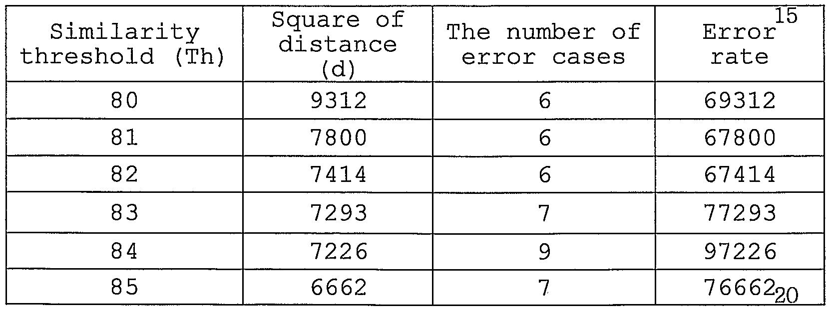
- the error rate of converged classes is calculated S247. As shown in Equation 8, the error rate is defined as the sum of the squares of the distance between each case in a class and the representative image of the class. The "distance" is conceptional. Actually, the error rate is represented by an error observation calculated on the assumption that dissimilarity between each case and its representative image is 100%.
- the re-clustering determination operation S250 is executed.
- the operation S255 of increasing the similarity threshold using Equation 9 is executed. If re-clustering is requested, clustering is again executed using an increased similarity threshold S255. If re-clustering is not requested, the similarity threshold and the k-value are determined S260. Since the initial similarity threshold (Th star t) is an approximate value, the k-value determined from the initial similarity threshold is also not completely suitable for assignment of given cases.
- the maximum similarity threshold (Th s ) can be obtained within permissible classes. For example, if the number of classes is smaller than the number of permissible classes, the process returns to the operation of clustering S220 and increases the similarity threshold by 1% to iterate assignment of all cases to classes .
- the similarity threshold and k-value corresponding to the smallest error rate among error rates calculated with an increased similarity threshold are determined to be the most suitable.
- the representative image matching operation S270 may be selectively performed.
- the number of classes can be reduced and a universal representative image can be created.
- an intervertebral implant is not fitted with spinous processes at a specific spot during scanning, the scanning is stopped and then again performed at another spot.
- the minimal error spot i.e., the minimal error space spot is searched and recorded. This matching procedure is performed by a voxel-based comparison of cases 271' and templates 273' configured for three-dimensional intervertebral implants.
- FIG. 36 is a detailed flow diagram of the representative image matching operation S270 of FIG. 30 and FIG. 37 is an exemplified view of the representative image matching.
- the representative image matching can be efficiently used in manufacturing a universal intervertebral implant suitable for most cases.
- the purposes of the representative image matching can be divided into two groups.
- an intervertebral implant has geometrically curved surfaces, and thus may differ from the three-dimensional shape of the representative image.
- the representative image matching reduces the number of intervertebral implants by a quantitative measurement of the error space between an intervertebral implant and a case, and ensures intervertebral implants with better adapted shapes.
- an intervertebral implant is manufactured to large dimensions considering the error rate.
- the representative image matching is to verify the enlarged dimensions. After determining the similarity threshold and the k-value, a case is provided (sub-operation S271) . The case is provided in a comparable shape.
- a two-dimensional image of an intervertebral implant adapted for a representative image is provided (sub-operation S272) .
- the widths of the spinous processes, an interspinous space, lower surface slopes of the spinous processes, the depths of the spinous processes, and others are measured.
- an intervertebral implant is manufactured so that it has slightly larger dimensions than the representative image.
- the intervertebral implant is now designated a "representative pattern.”
- a plurality of representative patterns can be manufactured according to the degree of margin in the dimensions. Adaptability of the representative patterns is determined through a matching procedure.
- the two-dimensional image of the intervertebral implant is provided so that a matching template can be provided and a region of interest (ROI) can be extracted from the matching template.
- the two-dimensional image of the intervertebral implant may be provided in the same form as the case.
- the intervertebral implant is provided as a cubic image of 64*64*10.
- a matching template adapted for the two- dimensional image of the intervertebral implant is provided (sub-operation S273) . This sub-operation is to detect the presence of spinous processes in a 180-degree range based on the centroid of the lower portion of the representative pattern both inside and outside the template.
- the matching template has a volume of 48*48*4. Referring to FIG.
- a matching template 273' is slightly larger than the two-dimensional image of the representative pattern to perform the matching with a case image . Then, a ROI is extracted from the matching template (sub-operation S274) . Referring to FIG. 37, a portion of the matching template is selected as a ROI 274' .
- a ROI with a size of 48*48 may be defined. In this case, the 48*48 ROI can scan a case region of 64*64 along with a variable space of 17*17.
- a gray level is assigned to the case image and the ROI of the matching template to discriminate the ROI from the case image, which is a target of comparison (sub- operation S275) .
- a gray level is assigned to the case image and the ROI of the matching template to discriminate the ROI from the case image, which is a target of comparison (sub- operation S275) .
- a case image zero (0) is assigned to a spinous process A and 255 is assigned to a background B.
- 100 is assigned to a background C and 255 is assigned to a matching template D. Since gray level assignment can also be performed using another gray level capable of discriminating the four regions, the present invention is not limited to the above-described examples.
- an error rate is calculated by matching the ROI of the matching template and the case (sub-operation S276) . Analysis results for the matching are given below with reference to FIG. 40. Referring to FIG. 40, there are about four regions.
- a region 1 containing only a template has a gray level of (255+255) /2 and is skipped in processing.
- a region 2 is an overlap of the case and the template and has a gray level of (0+255) /2.
- the spinous process of the case is larger than an intervertebral implant, there exists a protrusion of the spinous process from the template. When a voxel is detected during processing, the intervertebral implant is considered to be inappropriate.
- a region 3 contains only the spinous process of the case and has a gray level of (0+100) /2. Like region 1, region 3 is also skipped since it does not affect the processing.
- a region 4 contains only the backgrounds of the two images and represents an error space between the template and the case.
- Region 4 has a gray level of (255+100) /2, and the number of voxels is added cumulatively.
- the cumulative value of region 4 is computed as an error value and it is used to calculate the similarity threshold.
- the spinous process is not matched to the intervertebral implant.
- a space between the intervertebral implant and the spinous process increases.
- cumulative error values are calculated based on all error calculations. That is, in the case of matching a single matching template with a size of 48*48*4 and four slices, cumulative error values for the slices are calculated. Referring to FIG. 41, a matching template 920 is scanned along a variable space (17*17*5) in the x, y, or z direction in a case 910, and a cumulative error value for each position of the variable space is calculated.
- the above-described matching and error rate calculation can be implemented using Visual C++ as follows. For (Z_range) ⁇ For (X_range) ⁇ For (Y_range) ⁇ if (region_ ⁇ ) else if (region_ ( 2 ) ) loop exit ; else if (region_ ⁇ ))
- x_range, y_range, and z_range are respectively x, y, and z values of the variable space, k is the predetermined number of classes or representative images, and case is the number of cases.
- k is the predetermined number of classes or representative images
- case is the number of cases.
- scanning for a single representative image and a single case with a variable space of 17*17*5 is iterated 1,445 (17*17*5*1*1) times.
- Scanning for 40 representative images and 100 cases is iterated 5,780,000 (17*17*5*40*100) times.
- case assignment is not restricted by parameters , Table 8
- An intervertebral implant is manufactured with a margin of error, and therefore it does not perfectly fit an interspinous space.
- the same intervertebral implant can be used for the representative image of another class.
- case assignment to another class can be implemented.
- the representative image matching produces more general intervertebral implants.
- the representative image matching may be omitted. Table 9 presents (100-representative error rate) % of each case in each class. As described above, a • representative error value or a representative error rate may be used instead of (100-representative error rate)%.
- Table 9 shows matching results between each case and an intervertebral implant corresponding to the representative image of each class. From the matching results, a matching rate can be estimated. Also, since classes with very low matching rates can be filtered out, the matching results of Table 9 can be used as primary evaluation standards . Table 9
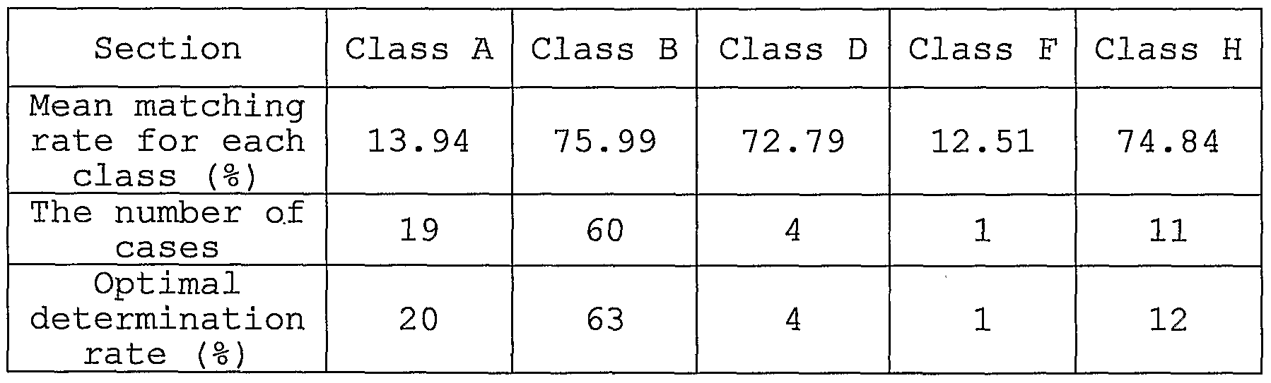
- Table 10 presents a mean matching rate for each class, the number of assigned cases, and an optimal determination rate.
- the mean matching rate indicates a mean of the (100- representative error rate) % values shown in Table 9, the number of cases indicates the number of cases assigned to each class, and the optimal determination rate indicates the ratio (%) of cases assigned to each class to the total number of cases.
- FIG. 42 is a perspective view illustrating a spacer 50 according to another embodiment of the present invention. Referring to FIG.
- the spacer 50 includes flanges 51a, 51b, 52a, and 52b and first and second notches 53a and 53b, like the above-described spacer 30.
- the spacer 50 slightly differs from the spacer 30 in that an elastic folding portion 54 imparting elasticity to the spacer 50 is further included and the first and second notches 53a and 53b are respectively formed with through- holes 55a and 55b.
- the elastic folding portion 54 is positioned at an insertion front part, and has one or more folds to impart elasticity to the spacer 50. Due to such a structural feature, even when the spacer 50 is made of a solid metal such as titanium, the space between upper and lower parts of the spacer 50 can be elastically changed within a predetermined range.
- the elastic folding portion 54 may include a vertical straight line portion 57a connected to the first notch 53a, a vertical straight line portion 57b connected to the second notch 53b, and a curved portion 56 connecting the two straight line portions .
- the straight line portions 57a and 57b serve to ensure a space corresponding to at least the sum of heights of the straight line portions 57a and 57b between spinous processes to prevent excessive spinal extension.
- the curved portion 56 serves to ensure elasticity of the elastic folding portion 54 upon extension or flexion.
- FIG. 43 is a diagrammatic lateral view of a spinal column illustrating the placement of the spacer 50 of FIG.
- a band 43 is inserted into the through-holes 55a and 55b of the spacer 50, like in the embodiment of FIG. 3.
- the band 43 binds an upper spinous process 3a, a lower spinous process 3b, and the spacer 50.
- a sectional view of the spacer 50 bound with the band 43 is shown in FIG.
- the band 43 surrounds the upper spinous process 3a and the lower spinous process 3b one or more times in a figure 8. Then, end portions of the band 43 are fixedly knotted. To prevent contact between the elastic folding portion 54 and the band 43 when the band 43 is inserted into the through-holes 55a and 55b, it is preferable that the band 43 be separated from the elastic folding portion 54 by a predetermined distance in the left and right direction of FIG. 43.
- the spacer 50 When the spacer 50 is placed between two adjacent spinous processes 3a and 3b as shown in FIG. 43, the space between the spinous processes 3a and 3b may be elastically changed. Therefore, the spacer 50 can adapt to a patient's motion while maintaining the space between the spinous processes 3a and 3b.
- FIG. 45 a spacer 60 according to a still another embodiment of the present invention is shown in FIG. 45.
- the spacer 60 is divided into upper and lower bodies 61 and 62 with notches.
- a lower portion of the upper body 61 is formed with a cylindrical receiver 63 and an upper portion of the lower body 62 is formed with an insertion member 64.
- the insertion member 64 is partially inserted into the cylindrical receiver 63.
- a separate connector is not provided for the coupling between the insertion member 64 and the cylindrical receiver 63.
- the cylindrical receiver 63 has a simple cylindrical shape.
- the insertion member 64 has such a shape that it can be partially inserted into the cylindrical receiver 63.
- the insertion member 64 has a conic shape that a first angle portion 66a of the left side (insertion front part) is steeper than a second angle portion 66b of the right side (insertion rear part) . Since there is no separate connector connecting the cylindrical receiver 63 and the insertion member 64, it is preferable that the first angle portion 66a and the second angle portion 66b have a curved shape to ensure relative movement of the cylindrical receiver 63 and the insertion member 64.
- the upper body 61 and the lower body 62 are respectively formed with band fixing projections 65a and 65b to bind the fixing projections 65a and 65b with the band (43 of FIG. 43) .
- the band -43 allows slight flexion within an elastic range due to the gradual slope of the second angle portion 66b, but it does not allow flexibility for extension due the steep slope of the first angle portion 66a.
- FIG. 47 is a diagrammatic lateral view of a spinal column illustrating the placement of the spacer 60 of FIG. 45 between adjacent spinous processes.
- the band fixing projections 65a and 65b are bound with a band 43.
- the tension of the band 43 can be maintained by contacting the first angle portion 66a of the insertion member 64 with an inner surface of the cylindrical receiver 63.
- Upper and lower spinous processes 3a and 3b may also be bound with a separate band near the pivot of the spacer 60.
- the spacer 60 has separate bodies independently supporting spinous processes. Therefore, the motion of spinous processes can be maximally permitted.
- the notches have a profile shape perpendicular to the flanges 44.
- the profile shape of a notch may be conformally curved to fit with a lower surface of a spinous process.
- the profile shapes of the notches of the embodiments shown in FIGS. 42 and 45 can be determined by the clustering method described with reference to FIGS. 22 through 28.
- an intervertebral implant of the present invention can be adapted to human spinous processes having different lower surface slopes.
Abstract
Description


Claims

Priority Applications (7)
| Application Number | Priority Date | Filing Date | Title |
|---|---|---|---|
| AU2005244312A AU2005244312B2 (en) | 2004-05-17 | 2005-05-17 | Spine insert |
| JP2006527925A JP4382092B2 (en) | 2004-05-17 | 2005-05-17 | Intervertebral insert |
| US11/596,853 US20080033552A1 (en) | 2004-05-17 | 2005-05-17 | Sensor Device |
| EP05740797A EP1746947A4 (en) | 2004-05-17 | 2005-05-17 | Spine insert |
| HK07111345.2A HK1102752A1 (en) | 2004-05-17 | 2007-10-20 | Spine insert |
| AU2008202617A AU2008202617B2 (en) | 2004-05-17 | 2008-06-13 | Spine insert |
| AU2008202620A AU2008202620A1 (en) | 2004-05-17 | 2008-06-13 | Spine insert |
Applications Claiming Priority (6)
| Application Number | Priority Date | Filing Date | Title |
|---|---|---|---|
| KR1020040034912A KR100545060B1 (en) | 2004-05-17 | 2004-05-17 | Method and system for clustering bone images |
| KR10-2004-0034921 | 2004-05-17 | ||
| KR10-2004-0034912 | 2004-05-17 | ||
| KR20040034921 | 2004-05-17 | ||
| KR10-2004-0062495 | 2004-08-09 | ||
| KR1020040062495A KR100620113B1 (en) | 2004-08-09 | 2004-08-09 | Spine Insert |
Publications (1)
| Publication Number | Publication Date |
|---|---|
| WO2005110258A1 true WO2005110258A1 (en) | 2005-11-24 |
Family
ID=35393955
Family Applications (1)
| Application Number | Title | Priority Date | Filing Date |
|---|---|---|---|
| PCT/KR2005/001451 WO2005110258A1 (en) | 2004-05-17 | 2005-05-17 | Spine insert |
Country Status (7)
| Country | Link |
|---|---|
| US (1) | US20080033552A1 (en) |
| EP (1) | EP1746947A4 (en) |
| JP (3) | JP4382092B2 (en) |
| AU (3) | AU2005244312B2 (en) |
| HK (1) | HK1102752A1 (en) |
| SG (2) | SG142310A1 (en) |
| WO (1) | WO2005110258A1 (en) |
Cited By (105)
| Publication number | Priority date | Publication date | Assignee | Title |
|---|---|---|---|---|
| WO2007127918A1 (en) * | 2006-04-28 | 2007-11-08 | Paradigm Spine, L.L.C. | Instrument system for use with an interspinous implant |
| WO2008029260A2 (en) * | 2006-09-07 | 2008-03-13 | Jean Taylor | Interspinous spinal prosthesis |
| US20080114455A1 (en) * | 2006-11-15 | 2008-05-15 | Warsaw Orthopedic, Inc. | Rotating Interspinous Process Devices and Methods of Use |
| WO2008130945A1 (en) * | 2007-04-18 | 2008-10-30 | Novara Limited Company | Interspinous process cushioned spacer |
| EP2016917A1 (en) | 2007-07-20 | 2009-01-21 | BioMed Ltd. | Implant for supporting spinous processes |
| US7662187B2 (en) | 2002-10-29 | 2010-02-16 | Kyphon Sarl | Interspinous process implants and methods of use |
| US7666209B2 (en) | 1997-01-02 | 2010-02-23 | Kyphon Sarl | Spine distraction implant and method |
| JP2010506695A (en) * | 2006-10-19 | 2010-03-04 | シンピライカ スパイン, インコーポレイテッド | Method and system for lateral stabilization restraint of spinous processes |
| JP2010506693A (en) * | 2006-10-19 | 2010-03-04 | シンピライカ スパイン, インコーポレイテッド | Structure and method for constraining spinous processes using a single connector |
| US7682376B2 (en) | 2006-01-27 | 2010-03-23 | Warsaw Orthopedic, Inc. | Interspinous devices and methods of use |
| US7691130B2 (en) | 2006-01-27 | 2010-04-06 | Warsaw Orthopedic, Inc. | Spinal implants including a sensor and methods of use |
| US7695513B2 (en) | 2003-05-22 | 2010-04-13 | Kyphon Sarl | Distractible interspinous process implant and method of implantation |
| US7727233B2 (en) | 2005-04-29 | 2010-06-01 | Warsaw Orthopedic, Inc. | Spinous process stabilization devices and methods |
| US7776069B2 (en) | 2002-09-10 | 2010-08-17 | Kyphon SÀRL | Posterior vertebral support assembly |
| US7780709B2 (en) | 2005-04-12 | 2010-08-24 | Warsaw Orthopedic, Inc. | Implants and methods for inter-transverse process dynamic stabilization of a spinal motion segment |
| US7789898B2 (en) | 2005-04-15 | 2010-09-07 | Warsaw Orthopedic, Inc. | Transverse process/laminar spacer |
| US7803190B2 (en) | 2002-10-29 | 2010-09-28 | Kyphon SÀRL | Interspinous process apparatus and method with a selectably expandable spacer |
| US7833246B2 (en) | 2002-10-29 | 2010-11-16 | Kyphon SÀRL | Interspinous process and sacrum implant and method |
| US7837711B2 (en) | 2006-01-27 | 2010-11-23 | Warsaw Orthopedic, Inc. | Artificial spinous process for the sacrum and methods of use |
| US7846186B2 (en) | 2005-06-28 | 2010-12-07 | Kyphon SÀRL | Equipment for surgical treatment of two vertebrae |
| US7846185B2 (en) | 2006-04-28 | 2010-12-07 | Warsaw Orthopedic, Inc. | Expandable interspinous process implant and method of installing same |
| US7862591B2 (en) | 2005-11-10 | 2011-01-04 | Warsaw Orthopedic, Inc. | Intervertebral prosthetic device for spinal stabilization and method of implanting same |
| US7862590B2 (en) | 2005-04-08 | 2011-01-04 | Warsaw Orthopedic, Inc. | Interspinous process spacer |
| US7879104B2 (en) | 2006-11-15 | 2011-02-01 | Warsaw Orthopedic, Inc. | Spinal implant system |
| US7909853B2 (en) | 2004-09-23 | 2011-03-22 | Kyphon Sarl | Interspinous process implant including a binder and method of implantation |
| US7922750B2 (en) | 2006-11-30 | 2011-04-12 | Paradigm Spine, Llc | Interlaminar-interspinous vertebral stabilization system |
| CN102014803A (en) * | 2008-04-22 | 2011-04-13 | 活动脊柱技术有限公司 | Artificial intervertebral spacer |
| US7927354B2 (en) | 2005-02-17 | 2011-04-19 | Kyphon Sarl | Percutaneous spinal implants and methods |
| US7931674B2 (en) | 2005-03-21 | 2011-04-26 | Kyphon Sarl | Interspinous process implant having deployable wing and method of implantation |
| US7955392B2 (en) | 2006-12-14 | 2011-06-07 | Warsaw Orthopedic, Inc. | Interspinous process devices and methods |
| US7959652B2 (en) | 2005-04-18 | 2011-06-14 | Kyphon Sarl | Interspinous process implant having deployable wings and method of implantation |
| US7985246B2 (en) | 2006-03-31 | 2011-07-26 | Warsaw Orthopedic, Inc. | Methods and instruments for delivering interspinous process spacers |
| US7988709B2 (en) | 2005-02-17 | 2011-08-02 | Kyphon Sarl | Percutaneous spinal implants and methods |
| US7993342B2 (en) | 2005-02-17 | 2011-08-09 | Kyphon Sarl | Percutaneous spinal implants and methods |
| US7993374B2 (en) | 1997-01-02 | 2011-08-09 | Kyphon Sarl | Supplemental spine fixation device and method |
| US7998174B2 (en) | 2005-02-17 | 2011-08-16 | Kyphon Sarl | Percutaneous spinal implants and methods |
| US7998208B2 (en) | 2005-02-17 | 2011-08-16 | Kyphon Sarl | Percutaneous spinal implants and methods |
| US8007521B2 (en) | 2005-02-17 | 2011-08-30 | Kyphon Sarl | Percutaneous spinal implants and methods |
| US8012209B2 (en) | 2004-09-23 | 2011-09-06 | Kyphon Sarl | Interspinous process implant including a binder, binder aligner and method of implantation |
| US8029567B2 (en) | 2005-02-17 | 2011-10-04 | Kyphon Sarl | Percutaneous spinal implants and methods |
| US8029549B2 (en) | 2005-02-17 | 2011-10-04 | Kyphon Sarl | Percutaneous spinal implants and methods |
| US8029550B2 (en) | 2006-01-18 | 2011-10-04 | Warsaw Orthopedic, Inc. | Intervertebral prosthetic device for spinal stabilization and method of implanting same |
| US8034079B2 (en) | 2005-04-12 | 2011-10-11 | Warsaw Orthopedic, Inc. | Implants and methods for posterior dynamic stabilization of a spinal motion segment |
| US8034080B2 (en) | 2005-02-17 | 2011-10-11 | Kyphon Sarl | Percutaneous spinal implants and methods |
| US8038698B2 (en) | 2005-02-17 | 2011-10-18 | Kphon Sarl | Percutaneous spinal implants and methods |
| US8043378B2 (en) | 2006-09-07 | 2011-10-25 | Warsaw Orthopedic, Inc. | Intercostal spacer device and method for use in correcting a spinal deformity |
| US8048117B2 (en) | 2003-05-22 | 2011-11-01 | Kyphon Sarl | Interspinous process implant and method of implantation |
| US8048119B2 (en) | 2006-07-20 | 2011-11-01 | Warsaw Orthopedic, Inc. | Apparatus for insertion between anatomical structures and a procedure utilizing same |
| US8048118B2 (en) | 2006-04-28 | 2011-11-01 | Warsaw Orthopedic, Inc. | Adjustable interspinous process brace |
| US8057513B2 (en) | 2005-02-17 | 2011-11-15 | Kyphon Sarl | Percutaneous spinal implants and methods |
| US8062337B2 (en) | 2006-05-04 | 2011-11-22 | Warsaw Orthopedic, Inc. | Expandable device for insertion between anatomical structures and a procedure utilizing same |
| US8066742B2 (en) | 2005-03-31 | 2011-11-29 | Warsaw Orthopedic, Inc. | Intervertebral prosthetic device for spinal stabilization and method of implanting same |
| US8070778B2 (en) | 2003-05-22 | 2011-12-06 | Kyphon Sarl | Interspinous process implant with slide-in distraction piece and method of implantation |
| US8083795B2 (en) | 2006-01-18 | 2011-12-27 | Warsaw Orthopedic, Inc. | Intervertebral prosthetic device for spinal stabilization and method of manufacturing same |
| US8092459B2 (en) | 2005-02-17 | 2012-01-10 | Kyphon Sarl | Percutaneous spinal implants and methods |
| US8096995B2 (en) | 2005-02-17 | 2012-01-17 | Kyphon Sarl | Percutaneous spinal implants and methods |
| US8097018B2 (en) | 2005-02-17 | 2012-01-17 | Kyphon Sarl | Percutaneous spinal implants and methods |
| US8096994B2 (en) | 2005-02-17 | 2012-01-17 | Kyphon Sarl | Percutaneous spinal implants and methods |
| US8097019B2 (en) | 2006-10-24 | 2012-01-17 | Kyphon Sarl | Systems and methods for in situ assembly of an interspinous process distraction implant |
| US8100943B2 (en) | 2005-02-17 | 2012-01-24 | Kyphon Sarl | Percutaneous spinal implants and methods |
| US8105363B2 (en) | 2004-03-09 | 2012-01-31 | The Board Of Trustees Of The Leland Stanford Junior University | Spinal implant and method for restricting spinal flexion |
| US8105358B2 (en) | 2008-02-04 | 2012-01-31 | Kyphon Sarl | Medical implants and methods |
| US8105357B2 (en) | 2006-04-28 | 2012-01-31 | Warsaw Orthopedic, Inc. | Interspinous process brace |
| US8114131B2 (en) | 2008-11-05 | 2012-02-14 | Kyphon Sarl | Extension limiting devices and methods of use for the spine |
| US8114132B2 (en) | 2010-01-13 | 2012-02-14 | Kyphon Sarl | Dynamic interspinous process device |
| US8114135B2 (en) | 2009-01-16 | 2012-02-14 | Kyphon Sarl | Adjustable surgical cables and methods for treating spinal stenosis |
| US8114136B2 (en) | 2008-03-18 | 2012-02-14 | Warsaw Orthopedic, Inc. | Implants and methods for inter-spinous process dynamic stabilization of a spinal motion segment |
| US8118839B2 (en) | 2006-11-08 | 2012-02-21 | Kyphon Sarl | Interspinous implant |
| US8118844B2 (en) | 2006-04-24 | 2012-02-21 | Warsaw Orthopedic, Inc. | Expandable device for insertion between anatomical structures and a procedure utilizing same |
| US8128661B2 (en) | 1997-01-02 | 2012-03-06 | Kyphon Sarl | Interspinous process distraction system and method with positionable wing and method |
| US8128663B2 (en) | 1997-01-02 | 2012-03-06 | Kyphon Sarl | Spine distraction implant |
| US8147526B2 (en) | 2010-02-26 | 2012-04-03 | Kyphon Sarl | Interspinous process spacer diagnostic parallel balloon catheter and methods of use |
| US8147548B2 (en) | 2005-03-21 | 2012-04-03 | Kyphon Sarl | Interspinous process implant having a thread-shaped wing and method of implantation |
| US8147517B2 (en) | 2006-05-23 | 2012-04-03 | Warsaw Orthopedic, Inc. | Systems and methods for adjusting properties of a spinal implant |
| US8157841B2 (en) | 2005-02-17 | 2012-04-17 | Kyphon Sarl | Percutaneous spinal implants and methods |
| US8157842B2 (en) | 2009-06-12 | 2012-04-17 | Kyphon Sarl | Interspinous implant and methods of use |
| US8162982B2 (en) | 2006-10-19 | 2012-04-24 | Simpirica Spine, Inc. | Methods and systems for constraint of multiple spine segments |
| US8187305B2 (en) | 2008-06-06 | 2012-05-29 | Simpirica Spine, Inc. | Methods and apparatus for deploying spinous process constraints |
| US8187307B2 (en) | 2006-10-19 | 2012-05-29 | Simpirica Spine, Inc. | Structures and methods for constraining spinal processes with single connector |
| US8216276B2 (en) | 2004-05-21 | 2012-07-10 | Warsaw Orthopedic, Inc. | Interspinous spacer |
| US8221465B2 (en) | 2006-04-28 | 2012-07-17 | Warsaw Orthopedic, Inc. | Multi-chamber expandable interspinous process spacer |
| US8252031B2 (en) | 2006-04-28 | 2012-08-28 | Warsaw Orthopedic, Inc. | Molding device for an expandable interspinous process implant |
| US8262698B2 (en) | 2006-03-16 | 2012-09-11 | Warsaw Orthopedic, Inc. | Expandable device for insertion between anatomical structures and a procedure utilizing same |
| US8308771B2 (en) | 2008-06-06 | 2012-11-13 | Simpirica Spine, Inc. | Methods and apparatus for locking a band |
| US8317831B2 (en) | 2010-01-13 | 2012-11-27 | Kyphon Sarl | Interspinous process spacer diagnostic balloon catheter and methods of use |
| US8348976B2 (en) | 2007-08-27 | 2013-01-08 | Kyphon Sarl | Spinous-process implants and methods of using the same |
| US8349013B2 (en) | 1997-01-02 | 2013-01-08 | Kyphon Sarl | Spine distraction implant |
| US8348978B2 (en) | 2006-04-28 | 2013-01-08 | Warsaw Orthopedic, Inc. | Interosteotic implant |
| US8357181B2 (en) | 2005-10-27 | 2013-01-22 | Warsaw Orthopedic, Inc. | Intervertebral prosthetic device for spinal stabilization and method of implanting same |
| US8372117B2 (en) | 2009-06-05 | 2013-02-12 | Kyphon Sarl | Multi-level interspinous implants and methods of use |
| US8403961B2 (en) | 2007-06-22 | 2013-03-26 | Simpirica Spine, Inc. | Methods and devices for controlled flexion restriction of spinal segments |
| US8403964B2 (en) | 2007-06-22 | 2013-03-26 | Simpirica Spine, Inc. | Methods and systems for increasing the bending stiffness and constraining the spreading of a spinal segment |
| US8523904B2 (en) | 2004-03-09 | 2013-09-03 | The Board Of Trustees Of The Leland Stanford Junior University | Methods and systems for constraint of spinous processes with attachment |
| US8529606B2 (en) | 2009-03-10 | 2013-09-10 | Simpirica Spine, Inc. | Surgical tether apparatus and methods of use |
| US8562650B2 (en) | 2011-03-01 | 2013-10-22 | Warsaw Orthopedic, Inc. | Percutaneous spinous process fusion plate assembly and method |
| US8562653B2 (en) | 2009-03-10 | 2013-10-22 | Simpirica Spine, Inc. | Surgical tether apparatus and methods of use |
| US8591548B2 (en) | 2011-03-31 | 2013-11-26 | Warsaw Orthopedic, Inc. | Spinous process fusion plate assembly |
| US8591549B2 (en) | 2011-04-08 | 2013-11-26 | Warsaw Orthopedic, Inc. | Variable durometer lumbar-sacral implant |
| US8668719B2 (en) | 2009-03-30 | 2014-03-11 | Simpirica Spine, Inc. | Methods and apparatus for improving shear loading capacity of a spinal segment |
| US8679161B2 (en) | 2005-02-17 | 2014-03-25 | Warsaw Orthopedic, Inc. | Percutaneous spinal implants and methods |
| US8690919B2 (en) | 2006-05-23 | 2014-04-08 | Warsaw Orthopedic, Inc. | Surgical spacer with shape control |
| US8771317B2 (en) | 2009-10-28 | 2014-07-08 | Warsaw Orthopedic, Inc. | Interspinous process implant and method of implantation |
| US8814908B2 (en) | 2010-07-26 | 2014-08-26 | Warsaw Orthopedic, Inc. | Injectable flexible interspinous process device system |
| US8840646B2 (en) | 2007-05-10 | 2014-09-23 | Warsaw Orthopedic, Inc. | Spinous process implants and methods |
| US9107706B2 (en) | 2009-03-10 | 2015-08-18 | Simpirica Spine, Inc. | Surgical tether apparatus and methods of use |
Families Citing this family (34)
| Publication number | Priority date | Publication date | Assignee | Title |
|---|---|---|---|---|
| US9055981B2 (en) | 2004-10-25 | 2015-06-16 | Lanx, Inc. | Spinal implants and methods |
| US8241330B2 (en) | 2007-01-11 | 2012-08-14 | Lanx, Inc. | Spinous process implants and associated methods |
| US7862592B2 (en) * | 2005-12-06 | 2011-01-04 | Nuvasive, Inc. | Methods and apparatus for treating spinal stenosis |
| US8048120B1 (en) * | 2006-05-31 | 2011-11-01 | Medicine Lodge, Inc. | System and method for segmentally modular spinal plating |
| US9265532B2 (en) | 2007-01-11 | 2016-02-23 | Lanx, Inc. | Interspinous implants and methods |
| US9247968B2 (en) | 2007-01-11 | 2016-02-02 | Lanx, Inc. | Spinous process implants and associated methods |
| US20110172708A1 (en) * | 2007-06-22 | 2011-07-14 | Simpirica Spine, Inc. | Methods and systems for increasing the bending stiffness of a spinal segment with elongation limit |
| EP2197374B1 (en) * | 2007-09-14 | 2018-10-31 | Synthes GmbH | Interspinous spacer |
| JP5162741B2 (en) * | 2007-12-05 | 2013-03-13 | 国立大学法人神戸大学 | Spinous process fixture |
| US8343190B1 (en) | 2008-03-26 | 2013-01-01 | Nuvasive, Inc. | Systems and methods for spinous process fixation |
| ES2574302T3 (en) * | 2008-08-08 | 2016-06-16 | Alphatec Spine, Inc. | Device for spinous process |
| ES2477581T3 (en) | 2009-08-27 | 2014-07-17 | Cotera, Inc. | Apparatus for redistribution of forces in joint joints |
| US10349980B2 (en) | 2009-08-27 | 2019-07-16 | The Foundry, Llc | Method and apparatus for altering biomechanics of the shoulder |
| US9668868B2 (en) | 2009-08-27 | 2017-06-06 | Cotera, Inc. | Apparatus and methods for treatment of patellofemoral conditions |
| US9861408B2 (en) | 2009-08-27 | 2018-01-09 | The Foundry, Llc | Method and apparatus for treating canine cruciate ligament disease |
| US9278004B2 (en) | 2009-08-27 | 2016-03-08 | Cotera, Inc. | Method and apparatus for altering biomechanics of the articular joints |
| US8758412B2 (en) | 2010-09-20 | 2014-06-24 | Pachyderm Medical, L.L.C. | Integrated IPD devices, methods, and systems |
| US8496689B2 (en) | 2011-02-23 | 2013-07-30 | Farzad Massoudi | Spinal implant device with fusion cage and fixation plates and method of implanting |
| KR101333657B1 (en) * | 2011-03-03 | 2013-11-27 | 정순명 | Vertebra Processes Fixture |
| US9498560B2 (en) | 2011-03-04 | 2016-11-22 | Spinefrontier, Inc | Interspinous spacer implant |
| US8425560B2 (en) | 2011-03-09 | 2013-04-23 | Farzad Massoudi | Spinal implant device with fixation plates and lag screws and method of implanting |
| FR2977139B1 (en) | 2011-06-30 | 2014-08-22 | Ldr Medical | INTER-SPINAL IMPLANT AND IMPLANTATION INSTRUMENT |
| USD757943S1 (en) | 2011-07-14 | 2016-05-31 | Nuvasive, Inc. | Spinous process plate |
| US8882805B1 (en) | 2011-08-02 | 2014-11-11 | Lawrence Maccree | Spinal fixation system |
| US11812923B2 (en) | 2011-10-07 | 2023-11-14 | Alan Villavicencio | Spinal fixation device |
| US10448977B1 (en) | 2012-03-31 | 2019-10-22 | Ali H. MESIWALA | Interspinous device and related methods |
| US9468466B1 (en) * | 2012-08-24 | 2016-10-18 | Cotera, Inc. | Method and apparatus for altering biomechanics of the spine |
| US9839450B2 (en) | 2013-09-27 | 2017-12-12 | Spinal Elements, Inc. | Device and method for reinforcement of a facet |
| KR101647457B1 (en) * | 2014-11-25 | 2016-08-10 | 주식회사 메드릭스 | Band coupling device for spinous process |
| KR101647453B1 (en) * | 2014-12-03 | 2016-08-10 | 주식회사 메드릭스 | Band fixing spacer device for spinous process |
| TWI627935B (en) * | 2017-01-24 | 2018-07-01 | 好喜歡妮有限公司 | Interspinous stabilizer |
| FR3083074B1 (en) * | 2018-06-29 | 2020-09-11 | Cousin Biotech | IMPLANTABLE DEVICE FOR THE FUSION OF TWO ADJACENT VERTEBRATES |
| CN113827379A (en) * | 2020-06-24 | 2021-12-24 | 好喜欢妮有限公司 | Interspinous process fixing device |
| US20220273442A1 (en) * | 2021-03-01 | 2022-09-01 | Spinal Elements, Inc. | Bone tie methods |
Citations (4)
| Publication number | Priority date | Publication date | Assignee | Title |
|---|---|---|---|---|
| WO2001028442A1 (en) * | 1999-10-15 | 2001-04-26 | Spine Next | Intervertebral implant |
| WO2002003882A2 (en) * | 2000-07-12 | 2002-01-17 | Spine Next | Shock-absorbing intervertebral implant |
| WO2002051326A1 (en) * | 2000-12-22 | 2002-07-04 | Spine Next | Intervertebral implant with deformable wedge |
| WO2002071960A1 (en) * | 2001-03-13 | 2002-09-19 | Spine Next | Self locking fixable intervertebral implant |
Family Cites Families (7)
| Publication number | Priority date | Publication date | Assignee | Title |
|---|---|---|---|---|
| FR2623085B1 (en) * | 1987-11-16 | 1992-08-14 | Breard Francis | SURGICAL IMPLANT TO LIMIT THE RELATIVE MOVEMENT OF VERTEBRES |
| FR2693364B1 (en) * | 1992-07-07 | 1995-06-30 | Erpios Snc | INTERVERTEBRAL PROSTHESIS FOR STABILIZING ROTATORY AND FLEXIBLE-EXTENSION CONSTRAINTS. |
| FR2722980B1 (en) * | 1994-07-26 | 1996-09-27 | Samani Jacques | INTERTEPINOUS VERTEBRAL IMPLANT |
| US6156038A (en) * | 1997-01-02 | 2000-12-05 | St. Francis Medical Technologies, Inc. | Spine distraction implant and method |
| FR2775183B1 (en) * | 1998-02-20 | 2000-08-04 | Jean Taylor | INTER-SPINOUS PROSTHESIS |
| FR2835173B1 (en) * | 2002-01-28 | 2004-11-05 | Biomet Merck France | INTERTEPINEOUS VERTEBRAL IMPLANT |
| US6808538B2 (en) * | 2002-03-15 | 2004-10-26 | Stryker Spine | Vertebral body spacer having variable wedged endplates |
-
2005
- 2005-05-17 SG SG200802973-8A patent/SG142310A1/en unknown
- 2005-05-17 EP EP05740797A patent/EP1746947A4/en not_active Withdrawn
- 2005-05-17 AU AU2005244312A patent/AU2005244312B2/en not_active Ceased
- 2005-05-17 WO PCT/KR2005/001451 patent/WO2005110258A1/en not_active Application Discontinuation
- 2005-05-17 SG SG200802970-4A patent/SG142309A1/en unknown
- 2005-05-17 US US11/596,853 patent/US20080033552A1/en not_active Abandoned
- 2005-05-17 JP JP2006527925A patent/JP4382092B2/en not_active Expired - Fee Related
-
2007
- 2007-10-20 HK HK07111345.2A patent/HK1102752A1/en not_active IP Right Cessation
-
2008
- 2008-06-13 AU AU2008202617A patent/AU2008202617B2/en not_active Expired - Fee Related
- 2008-06-13 AU AU2008202620A patent/AU2008202620A1/en not_active Abandoned
-
2009
- 2009-07-07 JP JP2009161263A patent/JP2009219921A/en active Pending
- 2009-07-07 JP JP2009161262A patent/JP2009219920A/en active Pending
Patent Citations (4)
| Publication number | Priority date | Publication date | Assignee | Title |
|---|---|---|---|---|
| WO2001028442A1 (en) * | 1999-10-15 | 2001-04-26 | Spine Next | Intervertebral implant |
| WO2002003882A2 (en) * | 2000-07-12 | 2002-01-17 | Spine Next | Shock-absorbing intervertebral implant |
| WO2002051326A1 (en) * | 2000-12-22 | 2002-07-04 | Spine Next | Intervertebral implant with deformable wedge |
| WO2002071960A1 (en) * | 2001-03-13 | 2002-09-19 | Spine Next | Self locking fixable intervertebral implant |
Non-Patent Citations (1)
| Title |
|---|
| See also references of EP1746947A4 * |
Cited By (161)
| Publication number | Priority date | Publication date | Assignee | Title |
|---|---|---|---|---|
| US7828822B2 (en) | 1997-01-02 | 2010-11-09 | Kyphon SÀRL | Spinous process implant |
| US8568454B2 (en) | 1997-01-02 | 2013-10-29 | Warsaw Orthopedic, Inc. | Spine distraction implant and method |
| US8568460B2 (en) | 1997-01-02 | 2013-10-29 | Warsaw Orthopedic, Inc. | Spine distraction implant and method |
| US7993374B2 (en) | 1997-01-02 | 2011-08-09 | Kyphon Sarl | Supplemental spine fixation device and method |
| US8617211B2 (en) | 1997-01-02 | 2013-12-31 | Warsaw Orthopedic, Inc. | Spine distraction implant and method |
| US8540751B2 (en) | 1997-01-02 | 2013-09-24 | Warsaw Orthopedic, Inc. | Spine distraction implant and method |
| US8029542B2 (en) | 1997-01-02 | 2011-10-04 | Kyphon Sarl | Supplemental spine fixation device and method |
| US7955356B2 (en) | 1997-01-02 | 2011-06-07 | Kyphon Sarl | Laterally insertable interspinous process implant |
| US7918877B2 (en) | 1997-01-02 | 2011-04-05 | Kyphon Sarl | Lateral insertion method for spinous process spacer with deployable member |
| US7666209B2 (en) | 1997-01-02 | 2010-02-23 | Kyphon Sarl | Spine distraction implant and method |
| US7901432B2 (en) | 1997-01-02 | 2011-03-08 | Kyphon Sarl | Method for lateral implantation of spinous process spacer |
| US8672975B2 (en) | 1997-01-02 | 2014-03-18 | Warsaw Orthopedic, Inc | Spine distraction implant and method |
| US8128661B2 (en) | 1997-01-02 | 2012-03-06 | Kyphon Sarl | Interspinous process distraction system and method with positionable wing and method |
| US8349013B2 (en) | 1997-01-02 | 2013-01-08 | Kyphon Sarl | Spine distraction implant |
| US8128663B2 (en) | 1997-01-02 | 2012-03-06 | Kyphon Sarl | Spine distraction implant |
| US8740943B2 (en) | 1997-01-02 | 2014-06-03 | Warsaw Orthopedic, Inc. | Spine distraction implant and method |
| US7749253B2 (en) | 1997-01-02 | 2010-07-06 | Kyphon SÀRL | Spine distraction implant and method |
| US7758619B2 (en) | 1997-01-02 | 2010-07-20 | Kyphon SÀRL | Spinous process implant with tethers |
| US8157840B2 (en) | 1997-01-02 | 2012-04-17 | Kyphon Sarl | Spine distraction implant and method |
| US8828017B2 (en) | 1997-01-02 | 2014-09-09 | Warsaw Orthopedic, Inc. | Spine distraction implant and method |
| US8821548B2 (en) | 1997-01-02 | 2014-09-02 | Warsaw Orthopedic, Inc. | Spine distraction implant and method |
| US8568455B2 (en) | 1997-01-02 | 2013-10-29 | Warsaw Orthopedic, Inc. | Spine distraction implant and method |
| US8672974B2 (en) | 1997-01-02 | 2014-03-18 | Warsaw Orthopedic, Inc. | Spine distraction implant and method |
| US8216277B2 (en) | 1997-01-02 | 2012-07-10 | Kyphon Sarl | Spine distraction implant and method |
| US7776069B2 (en) | 2002-09-10 | 2010-08-17 | Kyphon SÀRL | Posterior vertebral support assembly |
| US8043336B2 (en) | 2002-09-10 | 2011-10-25 | Warsaw Orthopedic, Inc. | Posterior vertebral support assembly |
| US8007537B2 (en) | 2002-10-29 | 2011-08-30 | Kyphon Sarl | Interspinous process implants and methods of use |
| US8221463B2 (en) | 2002-10-29 | 2012-07-17 | Kyphon Sarl | Interspinous process implants and methods of use |
| US7803190B2 (en) | 2002-10-29 | 2010-09-28 | Kyphon SÀRL | Interspinous process apparatus and method with a selectably expandable spacer |
| US7833246B2 (en) | 2002-10-29 | 2010-11-16 | Kyphon SÀRL | Interspinous process and sacrum implant and method |
| US8894686B2 (en) | 2002-10-29 | 2014-11-25 | Warsaw Orthopedic, Inc. | Interspinous process implants and methods of use |
| US8092535B2 (en) | 2002-10-29 | 2012-01-10 | Kyphon Sarl | Interspinous process implants and methods of use |
| US7662187B2 (en) | 2002-10-29 | 2010-02-16 | Kyphon Sarl | Interspinous process implants and methods of use |
| US8454659B2 (en) | 2002-10-29 | 2013-06-04 | Kyphon Sarl | Interspinous process implants and methods of use |
| US8888816B2 (en) | 2003-05-22 | 2014-11-18 | Warsaw Orthopedic, Inc. | Distractible interspinous process implant and method of implantation |
| US8070778B2 (en) | 2003-05-22 | 2011-12-06 | Kyphon Sarl | Interspinous process implant with slide-in distraction piece and method of implantation |
| US8048117B2 (en) | 2003-05-22 | 2011-11-01 | Kyphon Sarl | Interspinous process implant and method of implantation |
| US7695513B2 (en) | 2003-05-22 | 2010-04-13 | Kyphon Sarl | Distractible interspinous process implant and method of implantation |
| US9149304B2 (en) | 2004-03-09 | 2015-10-06 | The Board Of Trustees Of The Leland Sanford Junior University | Methods and systems for constraint of spinous processes with attachment |
| US8105363B2 (en) | 2004-03-09 | 2012-01-31 | The Board Of Trustees Of The Leland Stanford Junior University | Spinal implant and method for restricting spinal flexion |
| US10080589B2 (en) | 2004-03-09 | 2018-09-25 | The Board Of Trustees Of The Leland Stanford Junior University | Methods and systems for constraint of spinous processes with attachment |
| US8486110B2 (en) | 2004-03-09 | 2013-07-16 | The Board Of Trustees Of The Leland Stanford Junior University | Spinal implant and method for restricting spinal flexion |
| US8216275B2 (en) | 2004-03-09 | 2012-07-10 | The Board Of Trustees Of The Leland Stanford Junior University | Spinal implant and method for restricting spinal flexion |
| US8523904B2 (en) | 2004-03-09 | 2013-09-03 | The Board Of Trustees Of The Leland Stanford Junior University | Methods and systems for constraint of spinous processes with attachment |
| US8216276B2 (en) | 2004-05-21 | 2012-07-10 | Warsaw Orthopedic, Inc. | Interspinous spacer |
| US8012209B2 (en) | 2004-09-23 | 2011-09-06 | Kyphon Sarl | Interspinous process implant including a binder, binder aligner and method of implantation |
| US7909853B2 (en) | 2004-09-23 | 2011-03-22 | Kyphon Sarl | Interspinous process implant including a binder and method of implantation |
| US7988709B2 (en) | 2005-02-17 | 2011-08-02 | Kyphon Sarl | Percutaneous spinal implants and methods |
| US8092459B2 (en) | 2005-02-17 | 2012-01-10 | Kyphon Sarl | Percutaneous spinal implants and methods |
| US8096995B2 (en) | 2005-02-17 | 2012-01-17 | Kyphon Sarl | Percutaneous spinal implants and methods |
| US8454693B2 (en) | 2005-02-17 | 2013-06-04 | Kyphon Sarl | Percutaneous spinal implants and methods |
| US8029549B2 (en) | 2005-02-17 | 2011-10-04 | Kyphon Sarl | Percutaneous spinal implants and methods |
| US7993342B2 (en) | 2005-02-17 | 2011-08-09 | Kyphon Sarl | Percutaneous spinal implants and methods |
| US8147516B2 (en) | 2005-02-17 | 2012-04-03 | Kyphon Sarl | Percutaneous spinal implants and methods |
| US8157841B2 (en) | 2005-02-17 | 2012-04-17 | Kyphon Sarl | Percutaneous spinal implants and methods |
| US8034080B2 (en) | 2005-02-17 | 2011-10-11 | Kyphon Sarl | Percutaneous spinal implants and methods |
| US8043335B2 (en) | 2005-02-17 | 2011-10-25 | Kyphon Sarl | Percutaneous spinal implants and methods |
| US8029567B2 (en) | 2005-02-17 | 2011-10-04 | Kyphon Sarl | Percutaneous spinal implants and methods |
| US8007521B2 (en) | 2005-02-17 | 2011-08-30 | Kyphon Sarl | Percutaneous spinal implants and methods |
| US8038698B2 (en) | 2005-02-17 | 2011-10-18 | Kphon Sarl | Percutaneous spinal implants and methods |
| US7998174B2 (en) | 2005-02-17 | 2011-08-16 | Kyphon Sarl | Percutaneous spinal implants and methods |
| US8167890B2 (en) | 2005-02-17 | 2012-05-01 | Kyphon Sarl | Percutaneous spinal implants and methods |
| US7927354B2 (en) | 2005-02-17 | 2011-04-19 | Kyphon Sarl | Percutaneous spinal implants and methods |
| US8057513B2 (en) | 2005-02-17 | 2011-11-15 | Kyphon Sarl | Percutaneous spinal implants and methods |
| US8221458B2 (en) | 2005-02-17 | 2012-07-17 | Kyphon Sarl | Percutaneous spinal implants and methods |
| US8100943B2 (en) | 2005-02-17 | 2012-01-24 | Kyphon Sarl | Percutaneous spinal implants and methods |
| US8096994B2 (en) | 2005-02-17 | 2012-01-17 | Kyphon Sarl | Percutaneous spinal implants and methods |
| US7998208B2 (en) | 2005-02-17 | 2011-08-16 | Kyphon Sarl | Percutaneous spinal implants and methods |
| US8097018B2 (en) | 2005-02-17 | 2012-01-17 | Kyphon Sarl | Percutaneous spinal implants and methods |
| US8679161B2 (en) | 2005-02-17 | 2014-03-25 | Warsaw Orthopedic, Inc. | Percutaneous spinal implants and methods |
| US7931674B2 (en) | 2005-03-21 | 2011-04-26 | Kyphon Sarl | Interspinous process implant having deployable wing and method of implantation |
| US8591546B2 (en) | 2005-03-21 | 2013-11-26 | Warsaw Orthopedic, Inc. | Interspinous process implant having a thread-shaped wing and method of implantation |
| US8273107B2 (en) | 2005-03-21 | 2012-09-25 | Kyphon Sarl | Interspinous process implant having a thread-shaped wing and method of implantation |
| US8147548B2 (en) | 2005-03-21 | 2012-04-03 | Kyphon Sarl | Interspinous process implant having a thread-shaped wing and method of implantation |
| US8066742B2 (en) | 2005-03-31 | 2011-11-29 | Warsaw Orthopedic, Inc. | Intervertebral prosthetic device for spinal stabilization and method of implanting same |
| US7862590B2 (en) | 2005-04-08 | 2011-01-04 | Warsaw Orthopedic, Inc. | Interspinous process spacer |
| US8034079B2 (en) | 2005-04-12 | 2011-10-11 | Warsaw Orthopedic, Inc. | Implants and methods for posterior dynamic stabilization of a spinal motion segment |
| US7780709B2 (en) | 2005-04-12 | 2010-08-24 | Warsaw Orthopedic, Inc. | Implants and methods for inter-transverse process dynamic stabilization of a spinal motion segment |
| US7789898B2 (en) | 2005-04-15 | 2010-09-07 | Warsaw Orthopedic, Inc. | Transverse process/laminar spacer |
| US7959652B2 (en) | 2005-04-18 | 2011-06-14 | Kyphon Sarl | Interspinous process implant having deployable wings and method of implantation |
| US8128702B2 (en) | 2005-04-18 | 2012-03-06 | Kyphon Sarl | Interspinous process implant having deployable wings and method of implantation |
| US8109972B2 (en) | 2005-04-18 | 2012-02-07 | Kyphon Sarl | Interspinous process implant having deployable wings and method of implantation |
| US8226653B2 (en) | 2005-04-29 | 2012-07-24 | Warsaw Orthopedic, Inc. | Spinous process stabilization devices and methods |
| US7727233B2 (en) | 2005-04-29 | 2010-06-01 | Warsaw Orthopedic, Inc. | Spinous process stabilization devices and methods |
| US7846186B2 (en) | 2005-06-28 | 2010-12-07 | Kyphon SÀRL | Equipment for surgical treatment of two vertebrae |
| US8357181B2 (en) | 2005-10-27 | 2013-01-22 | Warsaw Orthopedic, Inc. | Intervertebral prosthetic device for spinal stabilization and method of implanting same |
| US7862591B2 (en) | 2005-11-10 | 2011-01-04 | Warsaw Orthopedic, Inc. | Intervertebral prosthetic device for spinal stabilization and method of implanting same |
| US8083795B2 (en) | 2006-01-18 | 2011-12-27 | Warsaw Orthopedic, Inc. | Intervertebral prosthetic device for spinal stabilization and method of manufacturing same |
| US8029550B2 (en) | 2006-01-18 | 2011-10-04 | Warsaw Orthopedic, Inc. | Intervertebral prosthetic device for spinal stabilization and method of implanting same |
| US7682376B2 (en) | 2006-01-27 | 2010-03-23 | Warsaw Orthopedic, Inc. | Interspinous devices and methods of use |
| US7691130B2 (en) | 2006-01-27 | 2010-04-06 | Warsaw Orthopedic, Inc. | Spinal implants including a sensor and methods of use |
| US8348977B2 (en) | 2006-01-27 | 2013-01-08 | Warsaw Orthopedic, Inc. | Artificial spinous process for the sacrum and methods of use |
| US8216279B2 (en) | 2006-01-27 | 2012-07-10 | Warsaw Orthopedic, Inc. | Spinal implant kits with multiple interchangeable modules |
| US7837711B2 (en) | 2006-01-27 | 2010-11-23 | Warsaw Orthopedic, Inc. | Artificial spinous process for the sacrum and methods of use |
| US8262698B2 (en) | 2006-03-16 | 2012-09-11 | Warsaw Orthopedic, Inc. | Expandable device for insertion between anatomical structures and a procedure utilizing same |
| US7985246B2 (en) | 2006-03-31 | 2011-07-26 | Warsaw Orthopedic, Inc. | Methods and instruments for delivering interspinous process spacers |
| US8118844B2 (en) | 2006-04-24 | 2012-02-21 | Warsaw Orthopedic, Inc. | Expandable device for insertion between anatomical structures and a procedure utilizing same |
| US7846185B2 (en) | 2006-04-28 | 2010-12-07 | Warsaw Orthopedic, Inc. | Expandable interspinous process implant and method of installing same |
| US8048118B2 (en) | 2006-04-28 | 2011-11-01 | Warsaw Orthopedic, Inc. | Adjustable interspinous process brace |
| US8105357B2 (en) | 2006-04-28 | 2012-01-31 | Warsaw Orthopedic, Inc. | Interspinous process brace |
| US8834482B2 (en) | 2006-04-28 | 2014-09-16 | Paradigm Spine, Llc | Instrument system for use with an interspinous implant |
| US11160585B2 (en) | 2006-04-28 | 2021-11-02 | Paradigm Spine, Llc | Instrument system for use with an interspinous implant |
| TWI426886B (en) * | 2006-04-28 | 2014-02-21 | Paradigm Spine Llc | Instrument system for use with an interspinous implant |
| US8348978B2 (en) | 2006-04-28 | 2013-01-08 | Warsaw Orthopedic, Inc. | Interosteotic implant |
| US8252031B2 (en) | 2006-04-28 | 2012-08-28 | Warsaw Orthopedic, Inc. | Molding device for an expandable interspinous process implant |
| US8221465B2 (en) | 2006-04-28 | 2012-07-17 | Warsaw Orthopedic, Inc. | Multi-chamber expandable interspinous process spacer |
| WO2007127918A1 (en) * | 2006-04-28 | 2007-11-08 | Paradigm Spine, L.L.C. | Instrument system for use with an interspinous implant |
| US8062337B2 (en) | 2006-05-04 | 2011-11-22 | Warsaw Orthopedic, Inc. | Expandable device for insertion between anatomical structures and a procedure utilizing same |
| US8147517B2 (en) | 2006-05-23 | 2012-04-03 | Warsaw Orthopedic, Inc. | Systems and methods for adjusting properties of a spinal implant |
| US8690919B2 (en) | 2006-05-23 | 2014-04-08 | Warsaw Orthopedic, Inc. | Surgical spacer with shape control |
| US8048119B2 (en) | 2006-07-20 | 2011-11-01 | Warsaw Orthopedic, Inc. | Apparatus for insertion between anatomical structures and a procedure utilizing same |
| WO2008029260A3 (en) * | 2006-09-07 | 2008-08-14 | Jean Taylor | Interspinous spinal prosthesis |
| JP2010502339A (en) * | 2006-09-07 | 2010-01-28 | ジャン・テイラー | Interspinous spine prosthesis |
| US8043378B2 (en) | 2006-09-07 | 2011-10-25 | Warsaw Orthopedic, Inc. | Intercostal spacer device and method for use in correcting a spinal deformity |
| WO2008029260A2 (en) * | 2006-09-07 | 2008-03-13 | Jean Taylor | Interspinous spinal prosthesis |
| US8790372B2 (en) | 2006-10-19 | 2014-07-29 | Simpirica Spine, Inc. | Methods and systems for constraint of multiple spine segments |
| US8162982B2 (en) | 2006-10-19 | 2012-04-24 | Simpirica Spine, Inc. | Methods and systems for constraint of multiple spine segments |
| US9295499B2 (en) | 2006-10-19 | 2016-03-29 | Empirical Spine, Inc. | Methods and systems for laterally stabilized constraint of spinous processes |
| US8187307B2 (en) | 2006-10-19 | 2012-05-29 | Simpirica Spine, Inc. | Structures and methods for constraining spinal processes with single connector |
| JP2010506693A (en) * | 2006-10-19 | 2010-03-04 | シンピライカ スパイン, インコーポレイテッド | Structure and method for constraining spinous processes using a single connector |
| US8029541B2 (en) | 2006-10-19 | 2011-10-04 | Simpirica Spine, Inc. | Methods and systems for laterally stabilized constraint of spinous processes |
| JP2010506695A (en) * | 2006-10-19 | 2010-03-04 | シンピライカ スパイン, インコーポレイテッド | Method and system for lateral stabilization restraint of spinous processes |
| US8454660B2 (en) | 2006-10-19 | 2013-06-04 | Simpirica Spine, Inc. | Methods and systems for laterally stabilized constraint of spinous processes |
| FR2907329A1 (en) * | 2006-10-20 | 2008-04-25 | Jean Taylor | Spinal prosthesis for implantation into interspinous gap between fifth lumbar and first sacral vertebrae, has intermediate portion defined in U-shaped implant, stuck against lower edge of fifth lumbar vertebra spinous process |
| US8641762B2 (en) | 2006-10-24 | 2014-02-04 | Warsaw Orthopedic, Inc. | Systems and methods for in situ assembly of an interspinous process distraction implant |
| US8097019B2 (en) | 2006-10-24 | 2012-01-17 | Kyphon Sarl | Systems and methods for in situ assembly of an interspinous process distraction implant |
| US8118839B2 (en) | 2006-11-08 | 2012-02-21 | Kyphon Sarl | Interspinous implant |
| US20080114455A1 (en) * | 2006-11-15 | 2008-05-15 | Warsaw Orthopedic, Inc. | Rotating Interspinous Process Devices and Methods of Use |
| US7879104B2 (en) | 2006-11-15 | 2011-02-01 | Warsaw Orthopedic, Inc. | Spinal implant system |
| US7922750B2 (en) | 2006-11-30 | 2011-04-12 | Paradigm Spine, Llc | Interlaminar-interspinous vertebral stabilization system |
| US7955392B2 (en) | 2006-12-14 | 2011-06-07 | Warsaw Orthopedic, Inc. | Interspinous process devices and methods |
| WO2008130945A1 (en) * | 2007-04-18 | 2008-10-30 | Novara Limited Company | Interspinous process cushioned spacer |
| US8840646B2 (en) | 2007-05-10 | 2014-09-23 | Warsaw Orthopedic, Inc. | Spinous process implants and methods |
| US8403961B2 (en) | 2007-06-22 | 2013-03-26 | Simpirica Spine, Inc. | Methods and devices for controlled flexion restriction of spinal segments |
| US8403964B2 (en) | 2007-06-22 | 2013-03-26 | Simpirica Spine, Inc. | Methods and systems for increasing the bending stiffness and constraining the spreading of a spinal segment |
| EP2016917A1 (en) | 2007-07-20 | 2009-01-21 | BioMed Ltd. | Implant for supporting spinous processes |
| US8348976B2 (en) | 2007-08-27 | 2013-01-08 | Kyphon Sarl | Spinous-process implants and methods of using the same |
| US8105358B2 (en) | 2008-02-04 | 2012-01-31 | Kyphon Sarl | Medical implants and methods |
| US8114136B2 (en) | 2008-03-18 | 2012-02-14 | Warsaw Orthopedic, Inc. | Implants and methods for inter-spinous process dynamic stabilization of a spinal motion segment |
| US8317832B2 (en) | 2008-03-18 | 2012-11-27 | Warsaw Orthopedic, Inc. | Implants and methods for inter-spinous process dynamic stabilization of spinal motion segment |
| CN102014803A (en) * | 2008-04-22 | 2011-04-13 | 活动脊柱技术有限公司 | Artificial intervertebral spacer |
| US8308771B2 (en) | 2008-06-06 | 2012-11-13 | Simpirica Spine, Inc. | Methods and apparatus for locking a band |
| US8187305B2 (en) | 2008-06-06 | 2012-05-29 | Simpirica Spine, Inc. | Methods and apparatus for deploying spinous process constraints |
| US8114131B2 (en) | 2008-11-05 | 2012-02-14 | Kyphon Sarl | Extension limiting devices and methods of use for the spine |
| US8114135B2 (en) | 2009-01-16 | 2012-02-14 | Kyphon Sarl | Adjustable surgical cables and methods for treating spinal stenosis |
| US8529606B2 (en) | 2009-03-10 | 2013-09-10 | Simpirica Spine, Inc. | Surgical tether apparatus and methods of use |
| US10314623B2 (en) | 2009-03-10 | 2019-06-11 | Empirical Spine, Inc. | Surgical tether apparatus and methods of use |
| US8562653B2 (en) | 2009-03-10 | 2013-10-22 | Simpirica Spine, Inc. | Surgical tether apparatus and methods of use |
| US9107706B2 (en) | 2009-03-10 | 2015-08-18 | Simpirica Spine, Inc. | Surgical tether apparatus and methods of use |
| US8668719B2 (en) | 2009-03-30 | 2014-03-11 | Simpirica Spine, Inc. | Methods and apparatus for improving shear loading capacity of a spinal segment |
| US8372117B2 (en) | 2009-06-05 | 2013-02-12 | Kyphon Sarl | Multi-level interspinous implants and methods of use |
| US8157842B2 (en) | 2009-06-12 | 2012-04-17 | Kyphon Sarl | Interspinous implant and methods of use |
| US8771317B2 (en) | 2009-10-28 | 2014-07-08 | Warsaw Orthopedic, Inc. | Interspinous process implant and method of implantation |
| US8114132B2 (en) | 2010-01-13 | 2012-02-14 | Kyphon Sarl | Dynamic interspinous process device |
| US8317831B2 (en) | 2010-01-13 | 2012-11-27 | Kyphon Sarl | Interspinous process spacer diagnostic balloon catheter and methods of use |
| US8840617B2 (en) | 2010-02-26 | 2014-09-23 | Warsaw Orthopedic, Inc. | Interspinous process spacer diagnostic parallel balloon catheter and methods of use |
| US8147526B2 (en) | 2010-02-26 | 2012-04-03 | Kyphon Sarl | Interspinous process spacer diagnostic parallel balloon catheter and methods of use |
| US8814908B2 (en) | 2010-07-26 | 2014-08-26 | Warsaw Orthopedic, Inc. | Injectable flexible interspinous process device system |
| US8562650B2 (en) | 2011-03-01 | 2013-10-22 | Warsaw Orthopedic, Inc. | Percutaneous spinous process fusion plate assembly and method |
| US8591548B2 (en) | 2011-03-31 | 2013-11-26 | Warsaw Orthopedic, Inc. | Spinous process fusion plate assembly |
| US8591549B2 (en) | 2011-04-08 | 2013-11-26 | Warsaw Orthopedic, Inc. | Variable durometer lumbar-sacral implant |
Also Published As
| Publication number | Publication date |
|---|---|
| EP1746947A4 (en) | 2010-05-05 |
| US20080033552A1 (en) | 2008-02-07 |
| JP2009219921A (en) | 2009-10-01 |
| HK1102752A1 (en) | 2007-12-07 |
| AU2008202617B2 (en) | 2010-07-29 |
| EP1746947A1 (en) | 2007-01-31 |
| AU2005244312A1 (en) | 2005-11-24 |
| SG142309A1 (en) | 2008-05-28 |
| JP4382092B2 (en) | 2009-12-09 |
| SG142310A1 (en) | 2008-05-28 |
| JP2009219920A (en) | 2009-10-01 |
| AU2008202620A1 (en) | 2008-07-03 |
| AU2005244312B2 (en) | 2008-07-03 |
| AU2008202617A1 (en) | 2008-07-03 |
| JP2007505720A (en) | 2007-03-15 |
Similar Documents
| Publication | Publication Date | Title |
|---|---|---|
| AU2005244312B2 (en) | Spine insert | |
| US8968365B2 (en) | Interspinous spacer | |
| Shufflebarger et al. | The posterior approach for lumbar and thoracolumbar adolescent idiopathic scoliosis: posterior shortening and pedicle screws | |
| Cidambi et al. | Postoperative Changes in Spinal Rod Contour in Adolescent Idiopathic Scoliosis: An: In Vivo Deformation Study | |
| JPH07505078A (en) | Variable implant for vertebral osteosynthesis with costotransverse bilaterally supported monoblock hooks | |
| US20080177320A1 (en) | Vertebral Rods and Methods of Use | |
| WO2002065954A1 (en) | Method and device for treating scoliosis | |
| CN100486538C (en) | Spine insert | |
| US20220409279A1 (en) | Systems and methods for planning a patient-specific spinal correction | |
| US20220387191A1 (en) | Patient-specific expandable spinal implants and associated systems and methods | |
| US9636149B2 (en) | Pedicle screw assembly and dynamic spinal stabilization devices incorporating the pedicle screw assembly | |
| CN115399874A (en) | Optimal implantation path planning method and device for pedicle screw and electronic equipment | |
| Seoud et al. | Changes in trunk appearance after scoliosis spinal surgery and their relation to changes in spinal measurements | |
| CN201591612U (en) | Intervertebral implant | |
| CN201591613U (en) | Vertebra inset | |
| Hadagali | Subject-specific finite element modeling of the adolescent thoracic spine for scoliosis research | |
| Smith et al. | Scoliosis: a straightforward approach to diagnosis and management | |
| US20230404624A1 (en) | Patient-specific spinal rod using 3d printing and pedicle fixation device including the same | |
| Soutome et al. | Preliminary Shape Similarity Analysis and Standardization for Pre-Bent Rod Design for Adult Spinal Deformity Correction | |
| US20220354511A1 (en) | Three-dimensional (3d) bone-protecting drill guide device and systems and methods of manufacturing and using device | |
| Raja et al. | A biomechanical study of the scoliotic thoracolumbar spine | |
| Ahmed et al. | Classification of Adolescent Idiopathic Scoliosis | |
| KR100620113B1 (en) | Spine Insert | |
| Zhang et al. | Kinematic analysis of lumbar spine undergoing extension and dynamic neural foramina cross section measurement | |
| Lama Seoud et al. | Changes in trunk appearance after scoliosis spinal surgery and their relation to changes in spinal measurements |
Legal Events
| Date | Code | Title | Description |
|---|---|---|---|
| AK | Designated states |
Kind code of ref document: A1 Designated state(s): AE AG AL AM AT AU AZ BA BB BG BR BW BY BZ CA CH CN CO CR CU CZ DE DK DM DZ EC EE EG ES FI GB GD GE GH GM HR HU ID IL IN IS JP KE KG KM KP KZ LC LK LR LS LT LU LV MA MD MG MK MN MW MX MZ NA NG NI NO NZ OM PG PH PL PT RO RU SC SD SE SG SK SL SM SY TJ TM TN TR TT TZ UA UG US UZ VC VN YU ZA ZM ZW |
|
| AL | Designated countries for regional patents |
Kind code of ref document: A1 Designated state(s): BW GH GM KE LS MW MZ NA SD SL SZ TZ UG ZM ZW AM AZ BY KG KZ MD RU TJ TM AT BE BG CH CY CZ DE DK EE ES FI FR GB GR HU IE IS IT LT LU MC NL PL PT RO SE SI SK TR BF BJ CF CG CI CM GA GN GQ GW ML MR NE SN TD TG |
|
| DPEN | Request for preliminary examination filed prior to expiration of 19th month from priority date (pct application filed from 20040101) | ||
| 121 | Ep: the epo has been informed by wipo that ep was designated in this application | ||
| WWE | Wipo information: entry into national phase |
Ref document number: 2006527925 Country of ref document: JP |
|
| WWE | Wipo information: entry into national phase |
Ref document number: 2005244312 Country of ref document: AU |
|
| WWE | Wipo information: entry into national phase |
Ref document number: 2005740797 Country of ref document: EP Ref document number: 11596853 Country of ref document: US Ref document number: 200580015917.8 Country of ref document: CN |
|
| NENP | Non-entry into the national phase |
Ref country code: DE |
|
| WWW | Wipo information: withdrawn in national office |
Ref document number: DE |
|
| ENP | Entry into the national phase |
Ref document number: 2005244312 Country of ref document: AU Date of ref document: 20050517 Kind code of ref document: A |
|
| WWP | Wipo information: published in national office |
Ref document number: 2005244312 Country of ref document: AU |
|
| WWP | Wipo information: published in national office |
Ref document number: 2005740797 Country of ref document: EP |
|
| WWP | Wipo information: published in national office |
Ref document number: 11596853 Country of ref document: US |