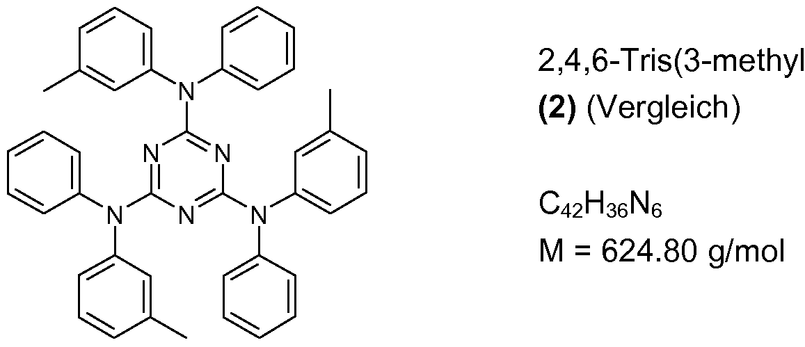
Verwendung von substituierten Tris(diphenylamino)-triazinverbindungen in OLEDs Use of substituted tris (diphenylamino) triazine compounds in OLEDs
Beschreibungdescription
Die vorliegende Erfindung betrifft eine organische Leuchtdiode enthaltend mindestens eine Tris(diphenylamino)-triazinverbindung mit mindestens einem Alkoxy- oder Aryloxy- rest, eine Licht-emittierende Schicht enthaltend mindestens eine Tris(diphenylamino)- triazinverbindung mit mindestens einem Alkoxy- oder Aryloxyrest, die Verwendung der vorstehend genannten Verbindungen als Matrixmaterial, Loch-/Excitonenblocker- material, Elektronen-/Excitonenblockermaterial, Loch-Injektionsmaterial, Elektronen- Injektionsmaterial, Lochleitermaterial und/oder Elektronenleitermaterial sowie eine Vorrichtung ausgewählt aus der Gruppe bestehend aus stationären Bildschirmen, mobilen Bildschirmen und Beleuchtungseinheiten enthaltend mindestens eine erfindungsgemäße organische Leuchtdiode.The present invention relates to an organic light-emitting diode containing at least one tris (diphenylamino) triazine compound having at least one alkoxy or aryloxy radical, a light-emitting layer containing at least one tris (diphenylamino) - triazine compound having at least one alkoxy or aryloxy, the use the abovementioned compounds as matrix material, hole / exciton blocker material, electron / exciton blocker material, hole injection material, electron injection material, hole conductor material and / or electron conductor material and a device selected from the group consisting of stationary screens, mobile screens and lighting units containing at least an organic light emitting diode according to the invention.
In organischen Leuchtdioden (OLED) wird die Eigenschaft von Materialien ausgenutzt, Licht zu emittieren, wenn sie durch elektrischen Strom angeregt werden. OLEDs sind insbesondere interessant als Alternative zu Kathodenstrahlröhren und zu Flüssigkristalldisplays zur Herstellung von Flachbildschirmen. Aufgrund der sehr kompakten Bau- weise und des intrinsisch niedrigen Stromverbrauchs eignen sich Vorrichtungen enthaltend OLEDs insbesondere für mobile Anwendungen, zum Beispiel für Anwendungen in Handys, Laptops, usw. sowie zur Beleuchtung.In organic light emitting diodes (OLEDs), the property of materials is used to emit light when excited by electric current. OLEDs are of particular interest as an alternative to cathode ray tubes and to liquid crystal displays for the manufacture of flat panel displays. Due to the very compact design and the intrinsically low power consumption, devices containing OLEDs are particularly suitable for mobile applications, for example for applications in mobile phones, laptops, etc. as well as for lighting.
Die Grundprinzipien der Funktionsweise von OLEDs sowie geeignete Aufbauten (Schichten) von OLEDs sind dem Fachmann bekannt und zum Beispiel in WO 2005/113704 und der darin zitierten Literatur genannt. Als Licht-emittierende Materialien (Emitter) können neben fluoreszierenden Materialien (Fluoreszenz-Emitter) phosphoreszierende Materialien (Phosphoreszenz-Emitter) eingesetzt werden. Bei den Phosphoreszenz-Emittern handelt es sich üblicherweise um metallorganische Komple- xe, die im Gegensatz zu den Fluoreszenz-Emittern, die eine Singulett-Emission zeigen, eine Triplett-Emission zeigen (Triplett-Emitter) (M. A. Baldow et al., Appl. Phys. Lett. 1999, 75, 4 bis 6). Aus quantenmechanischen Gründen ist bei der Verwendung der Triplett-Emitter (Phosphoreszenz-Emitter) eine bis zu vierfache Quanten-, Energie- und Leistungseffizienz möglich. Um die Vorteile des Einsatzes der metallorganischen Triplett-Emitter (Phosphoreszenz-Emitter) in die Praxis umzusetzen, ist es erforderlich, Device-Kompositionen bereitzustellen, die eine hohe operative Lebensdauer, eine gute Effizienz, eine hohe Stabilität gegenüber Temperaturbelastung und eine niedrige Einsatz- und Betriebsspannung aufweisen.The basic principles of the functioning of OLEDs and suitable structures (layers) of OLEDs are known to the person skilled in the art and are mentioned, for example, in WO 2005/113704 and the literature cited therein. As light-emitting materials (emitters), phosphorescent materials (phosphorescence emitters) can be used in addition to fluorescent materials (fluorescence emitters). The phosphorescence emitters are usually organometallic complexes, which exhibit triplet emission (triplet emitter) in contrast to fluorescence emitters which exhibit singlet emission (MA Baldow et al., Appl. Phys. Lett. 1999, 75, 4 to 6). For quantum mechanical reasons, when using the triplet emitter (phosphorescence emitter) up to fourfold quantum, energy and power efficiency is possible. In order to put into practice the advantages of using the organometallic triplet emitters (phosphorescent emitters), it is necessary to provide device compositions which have a long operating life, good efficiency, high stability against thermal stress, and low use and low energy consumption Operating voltage have.
Solche Device-Kompositionen können zum Beispiel spezielle Matrixmaterialien enthalten, in denen der eigentliche Lichtemitter in verteilter Form vorliegt. Des Weiteren kön-
nen die Kompositionen Blockermaterialien enthalten, wobei Loch-, Excitionen- und/oder Elektronenblocker in den Device-Kompositionen vorliegen können. Daneben oder alternativ können die Device-Kompositionen des Weiteren Loch- Injektionsmaterialien und/oder Elektronen-Injektionsmaterialien und/oder Lochleiterma- terialien und/oder Elektronenleitermaterialien aufweisen. Dabei hat die Auswahl der vorstehend genannten Materialien, die in Kombination mit dem eigentlichen Lichtemitter eingesetzt werden, einen wesentlichen Einfluss unter anderem auf die Effizienz sowie die Lebensdauer der OLEDs.Such device compositions may contain, for example, special matrix materials in which the actual light emitter is present in distributed form. Furthermore, nen the compositions contain blocker materials, which hole, Excitionen- and / or electron blocker may be present in the device compositions. In addition or alternatively, the device compositions may further comprise hole injection materials and / or electron injection materials and / or hole conductor materials and / or electron conductor materials. The selection of the above-mentioned materials, which are used in combination with the actual light emitter, has a significant influence, inter alia, on the efficiency and the lifetime of the OLEDs.
Im Stand der Technik werden zahlreiche verschiedene Materialien für den Einsatz in OLEDs vorgeschlagen. Unter den vorgeschlagenen Materialien sind auch solche, die Tris(diphenylamino)-triazinverbindungen aufweisen.Many different materials for use in OLEDs are proposed in the prior art. Among the suggested materials are also those having tris (diphenylamino) triazine compounds.
In EP 1 701 394 A1 sind OLEDs offenbart, die eine Licht-emittierende Schicht aufwei- sen, die aus einem Matrixpolymer und zwei oder mehr phosphoreszierenden Wirt- Materialien und mindestens einem phosphoreszierenden Dotiermatierial aufgebaut ist. Bei den phosphoreszierenden Wirt-Materialien kann es sich um Triazin-Verbindungen handeln. Als geeignete Triazin-Verbindungen sind 2,4,6-Tris(diarylamino)-1 ,3,5-triazin, 2,4,6-Tris(diphenylamino)-1 ,3,5-triazin, 2,4,6-tricarbazolo-1 ,3,5-triazin, 2,4,6-Tris(N- phenyl-2-naphthylamino)-1 ,3,5-triazin, 2,4,6-Tris(N-phenyl-1-naphthylamino)-1 ,3,5- triazin und 2,4,6-Trisbiphenyl-1 ,3,5-triazin genannt.EP 1 701 394 A1 discloses OLEDs which have a light-emitting layer which is composed of a matrix polymer and two or more phosphorescent host materials and at least one phosphorescent dopant material. The phosphorescent host materials may be triazine compounds. Suitable triazine compounds are 2,4,6-tris (diarylamino) -1, 3,5-triazine, 2,4,6-tris (diphenylamino) -1, 3,5-triazine, 2,4,6-tris tricarbazolo-1, 3,5-triazine, 2,4,6-tris (N-phenyl-2-naphthylamino) -1, 3,5-triazine, 2,4,6-tris (N-phenyl-1-naphthylamino ) -1, 3,5-triazine and 2,4,6-trisbiphenyl-1,3,5-triazine.
In EP 1 610 398 A2 sind OLEDs offenbart, die eine Licht-emittierende Schicht aufweisen, die aus einem Dotiermaterial und einem Wirt-Material aufgebaut sind. Das Wirt- Material umfasst mindestens eine Lochtransport-Verbindung und mindestens eine Verbindung, die eine Triazin-Verbindung sein kann. Als geeignete Triazin-Verbindungen sind 2,4,6-Tris(diarylamino)-1 ,3,5-triazin, 2,4,6-Tris(diphenylamino)-1 ,3,5-triazin, 2,4,6- tricarbazolo-1 ,3,5-triazin, 2,4,6-Tris(N-phenyl-2-naphthylamino)-1 ,3,5-triazin, 2,4,6- Tris(N-phenyl-1-naphthylamino)-1 ,3,5-triazin und 2,4,6-Trisbiphenyl-1 ,3,5-triazin ge- nannt.EP 1 610 398 A2 discloses OLEDs which have a light-emitting layer composed of a doping material and a host material. The host material comprises at least one hole transport compound and at least one compound which may be a triazine compound. Suitable triazine compounds are 2,4,6-tris (diarylamino) -1, 3,5-triazine, 2,4,6-tris (diphenylamino) -1, 3,5-triazine, 2,4,6-tris tricarbazolo-1, 3,5-triazine, 2,4,6-tris (N-phenyl-2-naphthylamino) -1, 3,5-triazine, 2,4,6-tris (N-phenyl-1-naphthylamino ) -1, 3,5-triazine and 2,4,6-trisbiphenyl-1,3,5-triazine.
JP 10-302960 A betrifft lumineszierende Materialien für OLEDs, wobei es sich unter anderem um Triazine handeln kann.JP 10-302960 A relates to luminescent materials for OLEDs, which may inter alia be triazines.
J. C. Li et al., Chem. Mater. 2004, 16, 471 1-4714 betrifft eine Studie von drei verschiedenen Typen von Aminen (Phenylendiamine, Benzidine und dendritische Arylamine) bezüglich ihrer Eignung als Lochtransportmaterialien in OLEDs. Ein Beispiel betrifft methoxysubstituierte Tris(diphenylamino)-triazinverbindungen, wobei die Metho- xygruppen in para-Position angeordnet sind. Das genannte Beispiel wird gegenüber den weiteren genannten Beispielen nicht als vorteilhaft dargestellt.
In US 5,716,722 sind OLEDs offenbart, die als Lochtransportmaterial eine Verbindung mit einem Triazinring mit mindestens einer direkt gebundenen Diphenylaminogruppe aufweisen. Gemäß US 5,716,722 sollen Lochtransportmaterialien bereit gestellt werden, die schwer kristallisieren, da die Kristallisation in der Lochtransportschicht zu Kurzschlüssen führen kann, so dass in den kristallisierten Bereichen keine Lichtemission erfolgt.JC Li et al., Chem. Mater. 2004, 16, 471 1-4714 relates to a study of three different types of amines (phenylenediamines, benzidines and dendritic arylamines) for their suitability as hole transport materials in OLEDs. One example relates to methoxy-substituted tris (diphenylamino) triazine compounds, where the methoxy groups are arranged in the para position. The example mentioned is not shown to be advantageous over the other examples mentioned. US Pat. No. 5,716,722 discloses OLEDs which, as hole transport material, have a compound with a triazine ring with at least one directly bound diphenylamino group. According to US 5,716,722 hole transport materials are to be provided, which are difficult to crystallize, since the crystallization in the hole transport layer can lead to short circuits, so that no light emission takes place in the crystallized areas.
V. Vaitkeviciene et al., Mol. Cryst. Liq. Cryst, Vol. 468, pp. 141/[493]-150/[502], 2007 betrifft aromatische Amine auf Triazinbasis, die als Ladungstransportmaterialien geeig- net sind. Ein symmetrisches Tris(ditolylamino)-substituierte Triazin wird mit unsymmetrischem 6-Phenyl-1 ,3,5-triazin verglichen. Dabei wird für das unsymmetrische Triazin eine hohe thermische Stabilität festegestellt. Des weiteren handelt es sich bei dem unsymmetrischen Triazin um ein im Temperaturbereich von 0 bis 3000C amorphes Material, während das symmetrische Triazin kristallisiert. Gemäß V. Vaitkeviciene et al. stellt das unsymmetrische Triazin ein potentielles Ladungstransportmaterial für elektro- lumineszierende Elemente dar. V. Vaitkeviciene et al. enthält jedoch kein Beispiel, worin die Eignung des unsymmetrischen Triazins als Ladungstransportmaterial in elektro- lumineszierenden Elementen gezeigt wird. Des Weiteren enthält V. Vaitkeviciene et al. keine Information betreffend eine Verlängerung der Lebensdauer von OLEDs bei Ein- satz des unsymmetrischen Triazins.V. Vaitkeviciene et al., Mol. Cryst. Liq. Cryst, Vol. 468, pp. 141 / [493] -150 / [502], 2007 relates to aromatic triazine-based amines which are suitable as charge transport materials. A symmetrical tris (ditolylamino) -substituted triazine is compared to unsymmetrical 6-phenyl-1,3,5-triazine. Here, a high thermal stability is found for the unsymmetrical triazine. Furthermore, the unsymmetrical triazine is an amorphous material in the temperature range from 0 to 300 ° C., while the symmetrical triazine crystallizes. According to V. Vaitkeviciene et al. For example, the unsymmetrical triazine is a potential charge transport material for electroluminescent elements. V. Vaitkeviciene et al. does not, however, show any example of the suitability of unsymmetrical triazine as a charge transport material in electroluminescent elements. Furthermore, V. Vaitkeviciene et al. No information regarding an extension of the lifetime of OLEDs when using the unsymmetrical triazine.
Aufgabe der vorliegenden Erfindung ist die Bereitstellung von Materialien, die für den Einsatz in OLEDs geeignet sind, insbesondere für den Einsatz als Matrixmaterial, insbesondere als Matrixmaterial in der Licht-emittierenden Schicht, Loch- /Excitonenblockermaterial, Elektronen-/Excitonenblockermaterial, Loch-Injektionsmaterial, Elektronen-Injektionsmaterial, Lochleitermaterial und/oder Elektronenleiterma- terial, die gegenüber den im Stand der Technik genannten Materialien verbesserte amorphe Eigenschaften aufweisen, das heißt, eine verringerte Kristallisationsneigung aufweisen, sowie die Bereitstellung von OLEDs mit einem verbesserten Eigenschafts- profil, das sich in einer verbesserten Performance, z.B. einer verlängerten Lebensdauer, gute Leuchtdichten, hohen Quantenausbeuten etc., zeigt.The object of the present invention is to provide materials which are suitable for use in OLEDs, in particular for use as matrix material, in particular as matrix material in the light-emitting layer, hole / exciton blocker material, electron / exciton blocker material, hole injection material, Electron injection material, hole conductor material and / or Elektronenleiterma- material, which have improved compared to the materials mentioned in the prior art amorphous properties, that is, have a reduced tendency to crystallize, as well as the provision of OLEDs with an improved property profile, which in a improved performance, eg a prolonged life, good luminance, high quantum yields, etc., shows.
Diese Aufgabe wird gelöst durch eine organische Leuchtdiode enthaltend mindestens eine Tris(diphenylamino)-triazinverbindung der allgemeinen Formel (I)
This object is achieved by an organic light-emitting diode containing at least one tris (diphenylamino) triazine compound of the general formula (I)
worin die Reste R1 bis R30 unabhängig voneinander die folgenden Bedeutungen aufweisen:wherein the radicals R 1 to R 30 independently of one another have the following meanings:
Wasserstoff, Alkyl, Cycloalkyl, Heterocycloalkyl, Aryl, Heteroaryl, OH, O-Alkyl, O-Aryl, O-Heterorayl, SH, S-Alkyl, S-Aryl, Halogen, Pseudohalogen, Amino oder weitere Sub- stituenten mit Donor- oder Akzeptorwirkung, oderHydrogen, alkyl, cycloalkyl, heterocycloalkyl, aryl, heteroaryl, OH, O-alkyl, O-aryl, O-heteroaryl, SH, S-alkyl, S-aryl, halogen, pseudohalogen, amino or further substituents with donor or Acceptor effect, or
ein Rest der Formel (i)a radical of the formula (i)
worin die Reste R1, R", Rd, R4, Rö, Rb, R', Rö, Ra, Rηu, R11, Rη", Rηd, R14, Rηö, Rηb, R17', R18', R19', R20', R21', R22', R23', R24' und R25' unabhängig voneinander die bezüglich
der Reste R1, R2, R3, R4, R5, R6, R7, R8, R9, R10, R11, R12, R13, R14, R15, R16, R17, R18, R19, R20, R21, R22, R23, R24 und R25 genannten Bedeutungen aufweisen;wherein the radicals R 1 , R ", R d , R 4 , R ö , R b , R ', R ö , R a , R ηu , R 11 , R η ", R ηd , R 14 , R ηö , R ηb, R 17 ', R 18', R 19 ', R 20', R 21 ', R 22', R 23 ', R 24' and R 25 'independently of one another with respect to the R 1 , R 2 , R 3 , R 4 , R 5 , R 6 , R 7 , R 8 , R 9 , R 10 , R 11 , R 12 , R 13 , R 14 , R 15 , R 16 , R 17 , R 18 , R 19 , R 20 , R 21 , R 22 , R 23 , R 24 and R 25 have mentioned meanings;
mit der Bedingung, dass mindestens einer der Reste mindestens einer der Reste R2, R4, R7, R9, R12, R14, R17, R19, R22, R24, R27 oder R29 O-Alkyl oder O-Aryl, bevorzugt O- Alkyl, bedeutet.with the proviso that at least one of the radicals R 2 , R 4 , R 7 , R 9 , R 12 , R 14 , R 17 , R 19 , R 22 , R 24 , R 27 or R 29 O- Alkyl or O-aryl, preferably O-alkyl.
Die Verbindungen der Formel I weisen somit mindestens einen Alkyloxy- oder Aryloxy- rest, bevorzugt mindestens einen Alkyloxyrest, in m-Position zu der mit dem Stickstoff- atom der Diphenylaminogruppen verknüpften Bindungsstelle der Phenylgruppen auf. Es wurde gefunden, dass sich Verbindungen der Formel I, die einen oder mehrere Substituenten in m-Position aufweisen, durch eine besonders geringe Kristallisationsneigung auszeichnen.The compounds of the formula I thus have at least one alkyloxy or aryloxy radical, preferably at least one alkyloxy radical, in the m-position relative to the binding site of the phenyl groups linked to the nitrogen atom of the diphenylamino groups. It has been found that compounds of the formula I which have one or more substituents in the m position are distinguished by a particularly low tendency to crystallize.
Unter dem Ausdruck „weitere Substituenten mit Donor- oder Akzeptorwirkung" sind die nachstehend genannten Substituenten mit Donor- oder Akzeptorwirkung zu verstehen, die nicht bereits in der Definition der Reste R1 bis R30 ausdrücklich genannt sind.The expression "further substituents with donor or acceptor action" is understood to mean the abovementioned substituents with donor or acceptor action which are not expressly mentioned in the definition of the radicals R 1 to R 30 .
Die vorliegende Erfindung betrifft somit speziell substituierte Tris(diphenylamino)- triazinverbindungen, die mindestens einen Alkoxy- oder Aryloxyrest aufweisen. Es wurde gefunden, dass sich diese Verbindungen sich durch eine besonders geringe Kristallisationsneigung auszeichnen und für den Einsatz in OLEDs besonders geeignet sind.The present invention thus relates specifically substituted tris (diphenylamino) - triazine compounds having at least one alkoxy or aryloxy. It has been found that these compounds are distinguished by a particularly low crystallization tendency and are particularly suitable for use in OLEDs.
In Abhängigkeit von ihrem Substitutionsmuster können die Verbindungen der Formel (I) entweder als Matrix, insbesondere als Matrix in der Licht-emittierenden Schicht, als Loch-/Excitonenblocker, als Elektronen-/Excitonenblocker, als Loch- Injektionsmaterialien, als Elektronen-Injektionsmaterialien, als Lochleiter und/oder als Elektronenleiter eingesetzt werden. Entsprechende Schichten von OLEDs sind dem Fachmann bekannt und zum Beispiel in WO 2005/113704 oder WO 2005/019373 genannt.Depending on their substitution pattern, the compounds of the formula (I) can be used either as a matrix, in particular as a matrix in the light-emitting layer, as a hole / exciton blocker, as electron / exciton blocker, as hole injection materials, as electron injection materials, as Hole conductor and / or used as an electron conductor. Corresponding layers of OLEDs are known to the person skilled in the art and are mentioned, for example, in WO 2005/113704 or WO 2005/019373.
Unter Alkyl sind substituierte oder unsubstituierte Ci-C2o-Alkylreste zu verstehen. Bevorzugt sind d- bis Cio-Alkylreste, besonders bevorzugt d- bis C6-Alkylreste. Die Al- kylreste können sowohl geradkettig als auch verzweigt sein. Des Weiteren können die Alkylreste mit einem oder mehreren Substituenten ausgewählt aus der Gruppe bestehend aus CrC2o-Alkoxy, Halogen, bevorzugt F, und C6-C3o-Aryl, das wiederum substituiert oder unsubstituiert sein kann, substituiert sein. Geeignete Arylsubstituenten sowie geeignete Alkoxy- und Halogensubstituenten sind nachstehend genannt. Beispiele für geeignete Alkylgruppen sind Methyl, Ethyl, Propyl, Butyl, Pentyl, Hexyl, Heptyl und Octyl sowie mit C6-C3o-Aryl-, Ci-C2O-AIkOXy- und/oder Halogen, insbesondere F, substi-
tuierte Derivate der genannten Alkylgruppen, zum Beispiel CF3. Dabei sind sowohl die n-lsomere der genannten Reste als auch verzweigte Isomere wie Isopropyl, Isobutyl, Isopentyl, sek-Butyl, tert-Butyl, Neopentyl, 3,3-Dimethylbutyl, 3-Ethylhexyl usw. mit umfasst. Bevorzugte Alkylgruppen sind Methyl, Ethyl, tert-Butyl und CF3.Alkyl is to be understood as meaning substituted or unsubstituted C 1 -C 20 -alkyl radicals. Preference is given to C 1 - to C 10 -alkyl radicals, particularly preferably C 1 to C 6 -alkyl radicals. The alkyl radicals can be both straight-chain and branched. Furthermore, the alkyl radicals may be substituted with one or more substituents selected from the group consisting of CrC 2 o-alkoxy, halogen, preferably F, and C 6 -C 3 o-aryl, which in turn may be substituted or unsubstituted substituted. Suitable aryl substituents as well as suitable alkoxy and halogen substituents are mentioned below. Examples of suitable alkyl groups are methyl, ethyl, propyl, butyl, pentyl, hexyl, heptyl and octyl, as well as C 6 -C 3 o-aryl, Ci-C 2O -AIkOXy- and / or halogen, especially F, substitutable substituted derivatives of said alkyl groups, for example CF 3 . Both the n-isomers of the radicals mentioned and branched isomers such as isopropyl, isobutyl, isopentyl, sec-butyl, tert-butyl, neopentyl, 3,3-dimethylbutyl, 3-ethylhexyl, etc. are included. Preferred alkyl groups are methyl, ethyl, tert-butyl and CF 3 .
Unter Cycloalkyl sind substituierte oder unsubstituierte C3-C2O-AI ky I reste zu verstehen. Bevorzugt sind C3- bis Cio-Alkylreste, besonders bevorzugt C3- bis C8-Alkylreste. Die Cycloalkylreste können einen oder mehrere der bezüglich der Alkylreste genannten Substituenten tragen. Beispiele für geeignete cyclische Alkylgruppen (Cycloalkylreste), die ebenfalls unsubstituiert oder mit den vorstehend bezüglich der Alkylgruppen genannten Resten substituiert sein können, sind Cyclopropyl, Cyclobutyl, Cyclopentyl, Cyclohexyl, Cycloheptyl, Cyclooctyl, Cyclononyl und Cyclodecyl. Gegebenenfalls kann es sich auch um polycyclische Ringsysteme handeln, wie Decalinyl, Norbornyl, Borna- nyl oder Adamantyl.By cycloalkyl are meant substituted or unsubstituted C 3 -C 2 O-AI ky I radicals. Preference is given to C 3 - to Cio-alkyl radicals, more preferably C 3 - to C 8 -alkyl radicals. The cycloalkyl radicals may carry one or more of the substituents mentioned with respect to the alkyl radicals. Examples of suitable cyclic alkyl groups (cycloalkyl radicals) which may likewise be unsubstituted or substituted by the radicals mentioned above with respect to the alkyl groups are cyclopropyl, cyclobutyl, cyclopentyl, cyclohexyl, cycloheptyl, cyclooctyl, cyclononyl and cyclodecyl. If appropriate, these may also be polycyclic ring systems, such as decalinyl, norbornyl, bornanyl or adamantyl.
Geeignete O-Alkyl- und S-Alkylgruppen sind Ci-C2o-Alkoxy- und C1-C20- Alkylthiogruppen und leiten sich entsprechend von den vorstehend genannten C1-C20- Alkylresten ab. Beispielsweise sind hier zu nennen OCH3, OC2H5, OC3H7, OC4H9 und OC8H17 sowie SCH3, SC2H5, SC3H7, SC4H9 und SC8H17. Dabei sind unter C3H7, C4H9 und C8H17 sowohl die n-lsomere als auch verzweigte Isomere wie iso-Propyl, iso-Butyl, sec-Butyl, tert-Butyl und 2-Ethylhexyl umfasst. Besonders bevorzugte Alkoxy- oder Alkylthio-Gruppen sind Methoxy, Ethoxy, n-Octyloxy, 2-Ethylhexyloxy und SCH3.Suitable O-alkyl and S-alkyl groups are Ci-C 2 o-alkoxy and C 1 -C 20 - alkylthio, and derive respectively from the above-mentioned C 1 -C 20 - alkyl radicals from. For example, OCH 3 , OC 2 H 5 , OC 3 H 7 , OC 4 H 9 and OC 8 H 17 and SCH 3 , SC 2 H 5 , SC 3 H 7 , SC 4 H 9 and SC 8 H 17 may be mentioned here , C 3 H 7 , C 4 H 9 and C 8 H 17 include both the n-isomers and branched isomers such as isopropyl, isobutyl, sec-butyl, tert-butyl and 2-ethylhexyl. Particularly preferred alkoxy or alkylthio groups are methoxy, ethoxy, n-octyloxy, 2-ethylhexyloxy and SCH 3 .
Geeignete Halogenreste oder Halogensubstituenten im Sinne der vorliegenden Anmel- düng sind Fluor, Chlor, Brom und lod, bevorzugt Fluor, Chlor und Brom, besonders bevorzugt Fluor und Chlor, ganz besonders bevorzugt Fluor.Suitable halogen radicals or halogen substituents for the purposes of the present application are fluorine, chlorine, bromine and iodine, preferably fluorine, chlorine and bromine, particularly preferably fluorine and chlorine, very particularly preferably fluorine.
Geeignete Pseudohalogenreste im Sinne der vorliegenden Anmeldung sind CN, SCN, OCN, N3 und SeCN zu verstehen, wobei CN und SCN bevorzugt sind. Ganz beson- ders bevorzugt ist CN.Suitable pseudohalogen radicals in the context of the present application are CN, SCN, OCN, N 3 and SeCN, CN and SCN being preferred. Most preferred is CN.
Als Arylreste sind C6-C3o-Arylreste geeignet, die von monocyclischen, bicyclischen oder tricyclischen Aromaten abgeleitet sind, die keine Ringheteroatome enthalten. Sofern es sich nicht um monocyclische Systeme handelt, ist bei der Bezeichnung Aryl für den zweiten Ring auch die gesättigte Form (Perhydroform) oder die teilweise ungesättigte Form (beispielsweise die Dihydroform oder Tetrahyroform), sofern die jeweiligen Formen bekannt und stabil sind, möglich. Das heißt, die Bezeichnung Aryl umfasst in der vorliegenden Erfindung beispielsweise auch bicyclische oder tricyclische Reste, in denen sowohl beide als auch alle drei Reste aromatisch sind, als auch bicyclische oder tricyclische Reste, in denen nur ein Ring aromatisch ist, sowie tricyclische Reste, worin zwei Ringe aromatisch sind. Beispiele für Aryl sind: Phenyl, Naphthyl, Indanyl, 1 ,2-
Dihydronaphthenyl, 1 ,4-Dihydronaphthenyl, Indenyl, Anthracenyl, Phenanthrenyl oder 1 ,2,3,4-Tetrahydronaphthyl. Besonders bevorzugt sind C6-Cio-Arylreste, zum Beispiel Phenyl oder Naphthyl, ganz besonders bevorzugt C6-Arylreste, zum Beispiel Phenyl.Aryl radicals C 6 -C 3 -aryl radicals suitable which are derived from monocyclic, bicyclic or tricyclic aromatic compounds that do not contain ring heteroatoms. Unless they are monocyclic systems, the term aryl for the second ring also means the saturated form (perhydroform) or the partially unsaturated form (for example the dihydroform or tetrahyroform), provided the respective forms are known and stable. That is, in the present invention, the term aryl includes, for example, bicyclic or tricyclic radicals in which both both and all three radicals are aromatic, as well as bicyclic or tricyclic radicals in which only one ring is aromatic, and tricyclic radicals wherein two rings are aromatic. Examples of aryl are: phenyl, naphthyl, indanyl, 1, 2 Dihydronaphthenyl, 1,4-dihydronaphthenyl, indenyl, anthracenyl, phenanthrenyl or 1,2,3,4-tetrahydronaphthyl. Particular preference is given to C 6 -C 10 -aryl radicals, for example phenyl or naphthyl, very particularly preferably C 6 -aryl radicals, for example phenyl.
Die Arylreste können unsubstituiert sein oder mit einem oder mehreren weiteren Resten substituiert sein. Geeignete weitere Reste sind ausgewählt aus der Gruppe bestehend aus CrC2o-Alkyl, C6-C30-Aryl oder Substituenten mit Donor- oder Akzeptorwirkung, wobei geeignete Substituenten mit Donor- oder Akzeptorwirkung nachstehend genannt sind. Bevorzugt sind die C6-C3o-Arylreste unsubstituiert oder mit einer oder mehreren Ci-C2o-Alkoxygruppen, CN, CF3, F oder Aminogruppen substituiert. Weitere bevorzugte Substitutionen der C6-C30-Arylreste sind abhängig von dem Einsatzzweck der Verbindungen der allgemeinen Formel (I) und sind nachstehend genannt.The aryl radicals may be unsubstituted or substituted by one or more further radicals. Suitable other radicals are selected from the group consisting of -C 2 -alkyl, C 6 -C 30 aryl or substituents having donor or acceptor, suitable substituents are mentioned with donor or acceptor below. The C 6 -C 3 are preferably unsubstituted o-aryl radicals or substituted with one or more Ci-C2 o alkoxy, CN, CF 3, F or amino groups. Further preferred substitutions of the C 6 -C 30 aryl radicals are dependent on the intended use of the compounds of the general formula (I) and are mentioned below.
Geeignete O-Aryl- und S-Arylreste sind C6-C3o-Aryloxy-, C6-C30-Al kylthioreste und lei- ten sich entsprechend von den vorstehend genannten C6-C30-Arylresten ab. Besonders bevorzugt sind Phenoxy und Phenylthio.Suitable O-aryl and S-aryl groups are C 6 -C 3 o-aryloxy, C 6 -C 30 -alkyl kylthioreste and managerial th correspondingly from the aforementioned C 6 -C 30 -aryl radicals from. Particularly preferred are phenoxy and phenylthio.
Unter Heteroaryl sind unsubstituierte oder substituierte Heteroarylreste mit 5 bis 30 Ringatomen, die monocyclisch, bicyclisch oder tricyclisch sein können, zu verstehen, die sich zum Teil vom vorstehend genannten Aryl ableiten lassen, in dem im Aryl- Grundgerüst mindestens ein Kohlenstoffatom durch ein Heteroatom ersetzt ist. Bevorzugte Heteroatome sind N, O und S. Besonders bevorzugt weisen die Heteroarylreste 5 bis 13 Ringatome auf. Insbesondere bevorzugt ist das Grundgerüst der Heteroarylreste ausgewählt aus Systemen wie Pyridin und fünfgliedrigen Heteroaromaten wie Thiophen, Pyrrol, Imidazol oder Furan. Diese Grundgerüste können gegebenenfalls mit einem oder zwei sechsgliedrigen aromatischen Resten anelliert sein. Geeignete anel- lierte Heteroaromaten sind Carbazolyl, Benzimidazolyl, Benzofuryl, Dibenzofuryl oder Dibenzothiophenyl. Das Grundgerüst kann an einer, mehreren oder allen substituierbaren Positionen substituiert sein, wobei geeignete Substituenten dieselben sind, die be- reits unter der Definition von C6-C30-Aryl genannt wurden. Bevorzugt sind die Heteroarylreste jedoch unsubstituiert. Geeignete Heteroarylreste sind zum Beispiel Pyridin-2-yl, Pyridin-3-yl, Pyridin-4-yl, Thiophen-2-yl, Thiophen-3-yl, Pyrrol-2-yl, Pyrrol-3-yl, Furan-2- yl, Furan-3-yl und lmidazol-2-yl sowie die entsprechenden benzanellierten Reste, insbesondere Carbazolyl, Benzimidazolyl, Benzofuryl, Dibenzofuryl oder Dibenzothiophe- nyl.Heteroaryl is to be understood as meaning unsubstituted or substituted heteroaryl radicals having 5 to 30 ring atoms, which may be monocyclic, bicyclic or tricyclic, some of which can be derived from the abovementioned aryl, in which at least one carbon atom in the aryl skeleton is replaced by a heteroatom , Preferred heteroatoms are N, O and S. Particularly preferably, the heteroaryl radicals have 5 to 13 ring atoms. Especially preferred is the backbone of the heteroaryl radicals selected from systems such as pyridine and five-membered heteroaromatics such as thiophene, pyrrole, imidazole or furan. These backbones may optionally be fused with one or two six-membered aromatic radicals. Suitable anellated heteroaromatics are carbazolyl, benzimidazolyl, benzofuryl, dibenzofuryl or dibenzothiophenyl. The backbone may be substituted at one, several or all substitutable positions, suitable substituents being the same as those already mentioned under the definition of C 6 -C 30 -aryl. Preferably, however, the heteroaryl radicals are unsubstituted. Suitable heteroaryl radicals are, for example, pyridin-2-yl, pyridin-3-yl, pyridin-4-yl, thiophen-2-yl, thiophen-3-yl, pyrrol-2-yl, pyrrol-3-yl, furan-2 - yl, furan-3-yl and imidazol-2-yl and the corresponding benzanellierten radicals, in particular carbazolyl, benzimidazolyl, benzofuryl, dibenzofuryl or dibenzothiophenyl.
Unter Aminogruppen sind Reste der allgemeinen Formel -NR31R32 zu verstehen, wobei geeignete Reste R31 und R32 nachstehend genannt sind. Beispiele für geeignete Aminogruppen sind Diarylaminogruppen wie Diphenylamino und Dialkylaminogruppen wie Dimethylamino, Diethylamino und Arylalkylaminogruppen wie Phenylmethylamino.
Unter Gruppen/Substituenten mit Donor- oder Akzeptorwirkung sind im Sinne der vorliegenden Anmeldung die folgenden Gruppen zu verstehen:Amino groups are radicals of the general formula -NR 31 R 32 , suitable radicals R 31 and R 32 being mentioned below. Examples of suitable amino groups are diarylamino groups such as diphenylamino and dialkylamino groups such as dimethylamino, diethylamino and arylalkylamino groups such as phenylmethylamino. For the purposes of the present application, groups / substituents with donor or acceptor action are understood to mean the following groups:
CrC20-AIkOXy, C6-C30-ArVIoXy, Ci-C20-Alkylthio, C6-C30-Arylt.hio, SiR31R32R33, Halogen- resten, halogenierten Ci-C20-Alkylresten, Carbonyl (-CO(R31)), Carbonylthio (- C = O (SR31)), Carbonyloxy (- C = 0(OR31)), Oxycarbonyl (- OC = 0(R31)), Thiocarbonyl (- SC = 0(R31)), Amino (-NR31R32), OH, Pseudohalogenresten, Amido (- C = O (NR31)), - NR31C = O (R32), Phosphonat (- P(O) (OR31)2, Phosphat (-OP(O) (OR31)2), Phosphin (- PR31R32), Phosphinoxid (-P(O)R31 2), Sulfat (-OS(O)2OR31), Sulfoxid (-S(O)R31), Sulfonat (-S(O)2OR31), Sulfonyl (-S(O)2R31), Sulfonamid (-S(O)2NR31R32), NO2, Boronsäurees- tern (-OB(OR31)2), Imino (-C = NR31R32)), Boranresten, Stannanresten, Hydrazinresten, Hydrazonresten, Oximresten, Nitroso-Gruppen, Diazo-Gruppen, Vinylgruppen, (=Sulfonat) und Boronsäuregruppen, Sulfoximine, Alane, Germane, Boroxime und Bo- razine.C 1 -C 20 -alkoxy, C 6 -C 30 -arvoyl, C 1 -C 20 -alkylthio, C 6 -C 30 -arylthio, SiR 31 R 32 R 33 , halogen radicals, halogenated C 1 -C 20 -alkyl radicals, carbonyl (-CO (R 31)) carbonylthio (- C = O (SR 31)), carbonyloxy (- C = 0 (OR 31)), oxycarbonyl (- OC = 0 (R 31)), thiocarbonyl (- SC = 0 (R 31 )), amino (-NR 31 R 32 ), OH, pseudohalo radicals, amido (- C = O (NR 31 )), - NR 31 C = O (R 32 ), phosphonate (- P (O) (OR 31 ) 2 , phosphate (-OP (O) (OR 31 ) 2 ), phosphine (- PR 31 R 32 ), phosphine oxide (-P (O) R 31 2 ), sulfate (-OS (O) 2 OR 31 ), sulfoxide (-S (O) R 31 ), sulfonate (-S (O) 2 OR 31 ), sulfonyl (-S (O) 2 R 31 ), sulfonamide (-S (O) 2 NR 31 R 32 ), NO 2 , boronic acid esters (-OB (OR 31 ) 2 ), imino (-C = NR 31 R 32 ), borane radicals, stannane radicals, hydrazine radicals, hydrazone radicals, oxime radicals, nitroso groups, diazo groups, vinyl groups, (= Sulfonate) and boronic acid groups, sulfoximines, alanes, germanes, boroximes and borazines.
Bevorzugte Substituenten mit Donor- oder Akzeptorwirkung sind ausgewählt aus der Gruppe bestehend aus:Preferred substituents with donor or acceptor action are selected from the group consisting of:
Cr bis C20-Alkoxy, bevorzugt d-Cβ-Alkoxy, besonders bevorzugt Ethoxy oder Metho- xy; C6-C30-Aryloxy, bevorzugt C6-Ci0-Aryloxy, besonders bevorzugt Phenyloxy; SiR31R32R33, wobei R31, R32 und R33 bevorzugt unabhängig voneinander substituiertes oder unsubstituiertes Alkyl oder substituiertes oder unsubstituiertes Phenyl bedeuten, wobei geeignete Substituenten vorstehend genannt sind, wobei SiR31R32R33 z.B. SiMe3 bedeutet; Halogenresten, bevorzugt F, Cl, Br, besonders bevorzugt F oder Cl, ganz besonders bevorzugt F, halogenierten CrC20-Alkylresten, bevorzugt halogenierten d- C6-Alkylresten, ganz besonders bevorzugt fluorierten CrC6-Alkylresten, z. B. CF3, CH2F, CHF2 oder C2F5; Amino, bevorzugt Dimethylamino, Diethylamino oder Dipheny- lamino; OH, Pseudohalogenresten, bevorzugt CN, SCN oder OCN, besonders bevorzugt CN, -C(O)OCrC4-Alkyl, bevorzugt -C(O)OMe, P(O)R2, bevorzugt P(O)Ph2 oder SO2R2, bevorzugt SO2Ph.C 1 to C 20 -alkoxy, preferably C 1 -C 6 -alkoxy, particularly preferably ethoxy or methoxy; C6-C 30 -aryloxy preferably, C 6 -C 0 aryloxy, most preferably phenyloxy; SiR 31 R 32 R 33 , wherein R 31 , R 32 and R 33 are preferably each independently substituted or unsubstituted alkyl or substituted or unsubstituted phenyl, suitable substituents being mentioned above, wherein SiR 31 R 32 R 33 eg SiMe 3 ; Halogen radicals, preferably F, Cl, Br, particularly preferably F or Cl, very particularly preferably F, halogenated C 1 -C 20 -alkyl radicals, preferably halogenated C 1 -C 6 -alkyl radicals, very particularly preferably fluorinated C 1 -C 6 -alkyl radicals, eg. CF 3 , CH 2 F, CHF 2 or C 2 F 5 ; Amino, preferably dimethylamino, diethylamino or diphenylamino; OH, pseudohalogen radicals, preferably CN, SCN or OCN, more preferably CN, -C (O) OC r C 4 alkyl, preferably -C (O) OMe, P (O) R 2 , preferably P (O) Ph 2 or SO 2 R 2 , preferably SO 2 Ph.
Ganz besonders bevorzugte Substituenten mit Donor- oder Akzeptorwirkung sind ausgewählt aus der Gruppe bestehend aus Methoxy, Phenyloxy, halogeniertem CrC4- Alkyl, bevorzugt CF3, CH2F, CHF2, C2F5, Halogen, bevorzugt F, CN, SiR14R15R16, wobei geeignete Reste R31, R32 und R33 bereits genannt sind, Diphenylamino, -C(O)OCrC4- Alkyl, bevorzugt -C(O)OMe, P(O)Ph2, SO2Ph.Very particularly preferred substituents having donor or acceptor selected from the group consisting of methoxy, phenyloxy, halogenated CrC 4 - alkyl, preferably CF 3, CH 2 F, CHF 2, C 2 F 5, halogen, preferably F, CN, SiR 14 R 15 R 16 , where suitable radicals R 31 , R 32 and R 33 are already mentioned, diphenylamino, -C (O) OCrC 4 -alkyl, preferably -C (O) OMe, P (O) Ph 2 , SO 2 Ph.
Durch die vorstehend genannten Gruppen mit Donor- oder Akzeptorwirkung soll nicht ausgeschlossen werden, dass auch weitere der vorstehend genannten Reste und Gruppen eine Donor- oder Akzeptorwirkung aufweisen können. Beispielsweise handelt es sich bei den vorstehend genannten Heteroarylresten ebenfalls um Gruppen mit Do-
nor- oder Akzeptorwirkung und bei den Ci-C2o-Alkylresten handelt es sich um Gruppen mit Donorwirkung.By the abovementioned groups with donor or acceptor action, it should not be ruled out that further of the abovementioned radicals and groups may also have a donor or acceptor action. For example, the heteroaryl radicals mentioned above are likewise groups with dopants. nor acceptor effect and the Ci-C 2 o-alkyl radicals are groups with donor action.
Die in den vorstehend genannten Gruppen mit Donor- oder Akzeptorwirkung erwähn- ten Reste R31, R32 und R33 haben die bereits vorstehend erwähnten Bedeutungen, d. h. R31, R32, R33 bedeuten unabhängig voneinander:The radicals R 31 , R 32 and R 33 mentioned in the abovementioned groups with donor or acceptor action have the meanings already mentioned above, ie R 31 , R 32 , R 33 independently of one another
Substituiertes oder unsubstituiertes CrC2o-Alkyl oder substituiertes oder unsubstituier- tes C6-C30-ArYl, wobei geeignete und bevorzugte Alkyl- und Arylreste vorstehend ge- nannt sind. Besonders bevorzugt bedeuten die Reste R31, R32 und R33 CrC6-Alkyl, z. B. Methyl, Ethyl oder i-Propyl oder substituiertes oder unsubstituiertes Phenyl.Substituted or unsubstituted C 2 o alkyl or substituted or unsubstituted C 6 -C 30 -aryl, where suitable and preferred alkyl and aryl radicals are above overall Nannt. Particularly preferably, the radicals R 31 , R 32 and R 33 C r C 6 alkyl, z. For example, methyl, ethyl or i-propyl or substituted or unsubstituted phenyl.
Bevorzugt in den Verbindungen der Formel I geeignete O-Alkylreste sind O-d- bis C8- Alkylreste, bevorzugt Methoxy-, Ethoxy-, n-Propyloxy-, iso-Propyloxy-, n-Butyloxy-, iso- Butyloxy, sek.-Butyloxy-, tert.-Butyloxyreste, besonders bevorzugt Methoxy- oder Etho- xyreste, ganz besonders bevorzugt Methoxyreste.O-alkyl radicals which are preferably suitable in the compounds of the formula I are C 2 - to C 8 -alkyl radicals, preferably methoxy, ethoxy, n-propyloxy, isopropoxy, n-butoxy, isobutoxy, sec-butyloxy -, tert-Butyloxyreste, more preferably methoxy or ethoxy radicals, most preferably methoxy radicals.
Bevorzugt in den Verbindungen der Formel I geeignete O-Arylreste sind 0-C6- bis C20- Arylreste, bevorzugt Phenyloxy- und Naphthyloxyreste, besonders bevorzugt Phenylo- xyreste, die gegebenenfalls mit d- bis Cs-Alkylresten substituiert sein können. Besonders bevorzugt sind unsubstituiertes Phenyloxy, 4-Alkylphenyloxy und 2,4,6- Trialkylphenyloxy.O-aryl radicals which are suitable in the compounds of the formula I are 0-C 6 - to C 20 -aryl radicals, preferably phenyloxy- and naphthyloxy radicals, more preferably phenoxy radicals, which may optionally be substituted by C 1 - to C 6 -alkyl radicals. Particularly preferred are unsubstituted phenyloxy, 4-alkylphenyloxy and 2,4,6-trialkylphenyloxy.
Die weiteren Reste R1 bis R30 weisen unabhängig voneinander die folgenden Bedeu- tungen auf:The further radicals R 1 to R 30 independently of one another have the following meanings:
Wasserstoff, Alkyl, Cycloalkyl, Heterocycloalkyl, Aryl, Heteroaryl, OH, O-Alkyl, O-Aryl, O-Heterorayl, SH, S-Alkyl, S-Aryl, Pseudohalogen, Halogen, Amino oder weitere Sub- stituenten mit Donor- oder Akzeptorwirkung, oderHydrogen, alkyl, cycloalkyl, heterocycloalkyl, aryl, heteroaryl, OH, O-alkyl, O-aryl, O-Heterorayl, SH, S-alkyl, S-aryl, pseudohalogen, halogen, amino or other substituents with donor or Acceptor effect, or
ein Rest der Formel (i)
a radical of the formula (i)
worin die Reste R1' R2' R3' R4' R5' R6' R7' R8' R9' R10' R11' R12' R13' R14' R15' R16' R17', R18', R19', R20', R21', R22', R23', R24' und R25' unabhängig voneinander die bezüglich der Reste R1, R2, R3, R4, R5, R6, R7, R8, R9, R10, R11, R12, R13, R14, R15, R16, R17, R18, R19, R20, R21, R22, R23, R24 und R25 genannten Bedeutungen aufweisen.wherein the radicals R 1 ' R 2' R 3 ' R 4' R 5 ' R 6' R 7 ' R 8' R 9 ' R 10' R 11 ' R 12' R 13 ' R 14' R 15 ' R 16 ' R 17' , R 18 ' , R 19' , R 20 ' , R 21' , R 22 ' , R 23' , R 24 ' and R 25' independently of one another with respect to the radicals R 1 , R 2 , R 3 , R 4 , R 5 , R 6 , R 7 , R 8 , R 9 , R 10 , R 11 , R 12 , R 13 , R 14 , R 15 , R 16 , R 17 , R 18 , R 19 , R 20 , R 21 , R 22 , R 23 , R 24 and R 25 have meanings mentioned.
Geeignete Alkyl-, Cycloalkyl-, Heterocycloalkyl-, Aryl-, Heteroaryl-, OH, O-Alkyl-, O- Aryl-, O-Heterorayl-, SH-, S-Alkyl-, S-Aryl-, Halogen-, Pseudohalogen- oder Aminoreste sind vorstehend genannt.Suitable alkyl, cycloalkyl, heterocycloalkyl, aryl, heteroaryl, OH, O-alkyl, O-aryl, O-Heterorayl, SH, S-alkyl, S-aryl, halogen, pseudohalogen - or amino radicals are mentioned above.
Bevorzugt bedeuten die weiteren Reste R1 bis R30 sowie R1 bis R25 unabhängig voneinander Wasserstoff, Alkyl, Cycloalkyl, O-Alkyl, O-Aryl, Aryl, SH, S-Alkyl, S-Aryl, Halogen, Pseudohalogen oder Amino, besonders bevorzugt Wasserstoff, Cr bis Cs- Alkyl, insbesondere Methyl, Ethyl, n-Propyl, i-Propyl, n-Butyl, i-Butyl, sek.-Butyl oder tert.-Butyl oder mit Halogen substituiertes d- bis C8-Alkyl, z.B. CF3, Aryl, insbesondere Phenyl, Halogen, insbesondere F oder Cl, Pseudohalogen, insbesondere CN, O-Alkyl , insbesondere O-Cr bis C8-Alkyl, O-Aryl, insbesondere O-C6-Aryl, oder SiR31R32R33, wobei die Reste R31, R32 und R33 CrC6-Alkyl, z. B. Methyl, Ethyl oder i-Propyl oder substituiertes oder unsubstituiertes Phenyl bedeuten, insbesondere SiMe3; ganz besonders bevorzugt Methyl, Ethyl, F, CN, CF3, SiMe3 oder O-Methyl.The further radicals R 1 to R 30 and R 1 to R 25 independently of one another preferably denote hydrogen, alkyl, cycloalkyl, O-alkyl, O-aryl, aryl, SH, S-alkyl, S-aryl, halogen, pseudohalogen or amino, particularly preferably hydrogen, C 1 - to C 6 -alkyl, in particular methyl, ethyl, n-propyl, isopropyl, n-butyl, isobutyl, sec-butyl or tert-butyl or halogen-substituted d- to C 8 - Alkyl, for example CF 3 , aryl, especially phenyl, halogen, in particular F or Cl, pseudohalogen, in particular CN, O-alkyl, in particular OC r to C 8 alkyl, O-aryl, in particular OC 6 -aryl, or SiR 31 R 32 R 33 , wherein the radicals R 31 , R 32 and R 33 C r C 6 alkyl, z. Methyl, ethyl or i-propyl or substituted or unsubstituted phenyl, in particular SiMe 3 ; most preferably methyl, ethyl, F, CN, CF 3 , SiMe 3 or O-methyl.
Die Verbindungen der Formel I können einen oder mehrere O-Alkyl- oder O-Arylreste aufweisen, die an beliebigen Positionen in dem Molekül vorliegen können, wobei min- destens ein O-Alkyl- oder O-Arylrest in m-Position zu der mit dem Stickstoffatom der Diphenylaminogruppen verknüpften Bindungsstelle der Phenylgruppen vorliegt. Bevorzugt weisen die Verbindungen der Formel I 1 , 2, 3, 4, 5 oder 6 O-Alkyl- und/oder O- Arylreste auf, besonders bevorzugt 1 , 2 oder 3 O-Alkyl- und/oder O-Arylreste. In einer bevorzugten Ausführungsform betrifft die vorliegende Erfindung Verbindungen der
Formel I, worin 1 , 2, 3, 4, 5 oder 6, bevorzugt 1 , 2 oder 3 der Reste R2, R4, R7, R9, R12, R14, R17, R19, R22, R24, R27 oder R29 O-Alkyl- und/oder O-Aryl bedeuten. Besonders geeignet sind z.B. Verbindungen der Formel I, worin R2, R7, R12, R17, R22 und R27 O-Alkyl- und/oder O-Aryl bedeuten, sowie Verbindungen der Formel I, worin R2, R12 und R22 O- Alkyl- und/oder O-Aryl bedeuten.The compounds of the formula I may have one or more O-alkyl or O-aryl radicals which may be present at any positions in the molecule, wherein at least one O-alkyl or O-aryl radical in the m position to the one with the Nitrogen atom of Diphenylaminogruppen linked binding site of the phenyl groups is present. The compounds of the formula I preferably have 1, 2, 3, 4, 5 or 6 O-alkyl and / or O-aryl radicals, more preferably 1, 2 or 3 O-alkyl and / or O-aryl radicals. In a preferred embodiment, the present invention relates to compounds of the Formula I, wherein 1, 2, 3, 4, 5 or 6, preferably 1, 2 or 3 of the radicals R 2 , R 4 , R 7 , R 9 , R 12 , R 14 , R 17 , R 19 , R 22 , R 24 , R 27 or R 29 are O-alkyl and / or O-aryl. Particularly suitable are, for example, compounds of the formula I in which R 2 , R 7 , R 12 , R 17 , R 22 and R 27 are O-alkyl- and / or O-aryl, and also compounds of the formula I in which R 2 , R 3 12 and R 22 is O-alkyl and / or O-aryl.
In einer weiteren Ausführungsform der vorliegenden Erfindung bedeuten die Reste R1, R5, R6, R10, R11, R15, R16, R20, R21, R25, R26 und R30 Wasserstoff. Das bedeutet, dass in einer Ausführungsform der vorliegenden Erfindung die Positionen in o-Position zu der mit dem Stickstoffatom der Diphenylaminogruppen verknüpften Bindungsstelle der Phenylgruppen mit Wasserstoff substituiert sind.In a further embodiment of the present invention, the radicals R 1 , R 5 , R 6 , R 10 , R 11 , R 15 , R 16 , R 20 , R 21 , R 25 , R 26 and R 30 are hydrogen. That is, in one embodiment of the present invention, the positions in the o-position to the bonding site of the phenyl groups linked to the nitrogen atom of the diphenylamino groups are substituted with hydrogen.
Die Positionen in p-Position zu der mit dem Stickstoff atom der Diphenylaminogruppen verknüpften Bindungsstelle der Phenylgruppen, R3, R8, R13, R18, R23 und R28, können jeweils unabhängig voneinander substituiert oder unsubstituiert sein (unter „unsubstitu- iert ist zu verstehen, dass die entsprechenden Reste Wasserstoff bedeuten). Geeignete Substituenten sind vorstehend genannt.The positions in the p-position to the binding site of the phenyl groups, R 3 , R 8 , R 13 , R 18 , R 23 and R 28 linked to the nitrogen atom of the diphenylamino groups may each be independently substituted or unsubstituted (under "unsubstituted"). It is understood that the corresponding radicals are hydrogen). Suitable substituents are mentioned above.
In einer Ausführungsform weisen die Verbindungen der Formel I die folgenden Formeln (Ia), (Ib), (Ic), (Id), (Ie) oder (If) auf:In one embodiment, the compounds of the formula I have the following formulas (Ia), (Ib), (Ic), (Id), (Ie) or (If):
worin R , R , R , R , R und R unabhängig voneinander die vorstehend genannten Bedeutungen aufweisen. Bevorzugt bedeuten R3, R8, R13, R18, R23 und R28 unabhängig voneinander Wasserstoff, Methyl, Ethyl, F, CF3, SiMe3 oder CN. In einer weiteren Ausführungsform bedeuten R3, R8, R13, R18, R23 und R28 bevorzugt unabhängig voneinander Methyl, Ethyl, F, CF3, SiMe3 oder CN.wherein R, R, R, R, R and R independently of one another have the meanings given above. R 3 , R 8 , R 13 , R 18 , R 23 and R 28 independently of one another preferably denote hydrogen, methyl, ethyl, F, CF 3 , SiMe 3 or CN. In a further embodiment, R 3 , R 8 , R 13 , R 18 , R 23 and R 28 preferably independently of one another are methyl, ethyl, F, CF 3 , SiMe 3 or CN.
Die Reste R2, R4, R7, R9, R12, R14, R17, R22, R24, R27 und R29 in den Verbindungen der Formeln Ia, Ib, Ic, Id, Ie und If weisen - soweit sie nicht OCH3 bedeuten - unabhängig voneinander die vorstehend genannten Bedeutungen auf. Bevorzugt bedeuten R2, R4, R7, R9, R12, R14, R17, R22, R24, R27 oder R29 - soweit sie nicht OCH3 bedeuten - Wasserstoff oder d- bis C4-Alkyl.The radicals R 2 , R 4 , R 7 , R 9 , R 12 , R 14 , R 17 , R 22 , R 24 , R 27 and R 29 in the compounds of the formulas Ia, Ib, Ic, Id, Ie and If - unless they are OCH 3 - independently of one another have the meanings given above. Preferably, R 2, R 4, R 7, R 9, R 12, R 14, R 17, R 22, R 24, R 27 or R 29 represent - as far as they do not represent OCH 3 - hydrogen or d- to C 4 - alkyl.
Die Herstellung der erfindungsgemäß verwendeten Tris(diphenylamino)- triazinverbindungen der allgemeinen Formel I erfolgt gemäß dem Fachmann bekannten Verfahren, z.B. durch nucleophile Substitution von Tris-1 ,3,5-trichloro-2,4,6-triazin mit geeigneten Li-Diarylamiden, z.B. entsprechend dem in H. Inomata et al., Chemistry of Materials 2004, 16, 1285 genannten Verfahren. In dem folgenden Schema 1 ist bei- spielhaft ein allgemeines Reaktionsschema zur Herstellung der Verbindungen der Formel I gezeigt:
The tris (diphenylamino) -triazine compounds of the general formula I used according to the invention are prepared by processes known to the person skilled in the art, for example by nucleophilic substitution of tris-1,3,5-trichloro-2,4,6-triazine with suitable Li-diarylamides, eg according to the method mentioned in H. Inomata et al., Chemistry of Materials 2004, 16, 1285. The following scheme 1 shows by way of example a general reaction scheme for the preparation of the compounds of the formula I:
Schema 1Scheme 1
Die in dem Schema 1 dargestellten Reste R1 bis R30 weisen die vorstehend genannten Bedeutungen auf.The radicals R 1 to R 30 shown in Scheme 1 have the meanings given above.
Die Verbindungen der Formel (I) sind hervorragend für den Einsatz als Matrixmaterialien in organischen Leuchtdioden geeignet. Insbesondere sind sie als Matrixmaterialien
in der Licht-emittierenden Schicht der OLEDs geeignet, wobei die Licht-emittierende Schicht als Emitter-Verbindungen bevorzugt einen oder mehrere Triplett-Emitter enthält.The compounds of the formula (I) are outstandingly suitable for use as matrix materials in organic light-emitting diodes. In particular, they are as matrix materials in the light-emitting layer of the OLEDs, wherein the light-emitting layer preferably contains one or more triplet emitters as emitter compounds.
Des Weiteren sind die Verbindungen der Formel (I) als Loch- /Excitonenblockermaterial, Elektronen-/Excitonenblockermaterial, Loch-Injektionsmaterial, Elektronen-Injektionsmaterial, Lochleitermaterial und/oder Elektronenleiterma- terial geeignet, wobei sie bevorzugt gemeinsam mit mindestens einem Triplett-Emitter in der erfindungsgemäßen OLED eingesetzt werden.Furthermore, the compounds of the formula (I) are suitable as hole / exciton blocker material, electron / exciton blocker material, hole injection material, electron injection material, hole conductor material and / or electron conductor material, wherein they preferably together with at least one triplet emitter in the OLED invention are used.
Die Funktion der Verbindungen der Formel (I) als Matrixmaterial, bevorzugt in der Licht -emittierenden Schicht, als Loch-/Excitonenblockermaterial, als Elektronen- /Excitonenblockermaterial, als Loch-Injektionsmaterial, als Elektronen- Injektionsmaterial, als Lochleitermaterial oder als Elektronenleitermaterial ist unter an- derem abhängig von den elektronischen Eigenschaften der Verbindungen der Formel (I), d.h. von dem Substitutionsmuster der Verbindungen der Formel (I), sowie des Weiteren von den elektronischen Eigenschaften (relative Lagen der HOMOs und LUMOs) der jeweiligen in der erfindungsgemäßen OLED eingesetzten Schichten. Somit ist es möglich, durch geeignete Substitution der Verbindungen der Formel (I) die HOMO und LUMO-Orbitallagen an die weiteren in der erfindungsgemäßen OLED eingesetzten Schichten anzupassen und so eine hohe Stabilität der OLED und damit eine lange o- perative Lebensdauer und gute Effizienzen zu erreichen.The function of the compounds of formula (I) as a matrix material, preferably in the light-emitting layer, as a hole / Excitonenblockermaterial, as electron / Excitonenblockermaterial, as a hole-injection material, as an electron injection material, as a hole conductor material or as an electron conductor material is under - derem depending on the electronic properties of the compounds of formula (I), ie from the substitution pattern of the compounds of the formula (I), and furthermore from the electronic properties (relative positions of the HOMOs and LUMOs) of the respective layers used in the OLED according to the invention. Thus, by suitable substitution of the compounds of the formula (I), it is possible to adapt the HOMO and LUMO orbital layers to the further layers used in the OLED according to the invention and thus to achieve a high stability of the OLED and thus a long operating life and good efficiencies to reach.
Die Grundsätze betreffend die relativen Lagen von HOMO und LUMO in den einzelnen Schichten einer OLED sind dem Fachmann bekannt. Im Folgenden sind die Grundsätze beispielhaft bezüglich der Eigenschaften der Blockschicht für Elektronen und der Blockschicht für Löcher im Verhältnis zur Licht-emittierenden Schicht aufgeführt:The principles relating to the relative locations of HOMO and LUMO in the individual layers of an OLED are known to those skilled in the art. The following are the principles by way of example with respect to the properties of the block layer for electrons and the block layer for holes in relation to the light-emitting layer:
Das LUMO der Blockschicht für Elektronen liegt energetisch höher als das LUMO der in der Licht-emittierenden Schicht eingesetzten Materialien (sowohl des Emittermaterials auch gegebenenfalls eingesetzter Matrixmaterialien). Je größer die energetische Differenz der LUMOs der Blockschicht für Elektronen und der Materialien in der Lichtemittierenden Schicht ist, desto besser sind die Elektronen- und/oder Excitonen- blockierenden Eigenschaften der Blockschicht für Elektronen. Geeignete Substituti- onsmuster der als Elektronen- und/oder Excitonenblockermaterialien geeigneten Verbindungen der Formel (I) sind somit unter anderem abhängig von den elektronischen Eigenschaften (insbesondere der Lage des LUMOs) der in der Licht-emittierenden Schicht eingesetzten Materialien.The LUMO of the block layer for electrons is higher in energy than the LUMO of the materials used in the light-emitting layer (both of the emitter material and optionally used matrix materials). The greater the energy difference of the LUMOs of the block layer for electrons and the materials in the light emitting layer, the better the electron and / or exciton blocking properties of the block layer for electrons. Suitable substitution patterns of the compounds of the formula (I) which are suitable as electron and / or exciton blocker materials are thus dependent inter alia on the electronic properties (in particular the position of the LUMO) of the materials used in the light-emitting layer.
Das HOMO der Blockschicht für Löcher liegt energetisch tiefer als die HOMOs der in der Licht-emittierenden Schicht vorliegenden Materialien (sowohl der Emittermateria-
lien als auch der gegebenenfalls vorliegenden Matrixmaterialien). Je größer die energetische Differenz der HOMOs der Blockschicht für Löcher und der in der Lichtemittierenden Schicht vorliegenden Materialien ist, desto besser sind die Loch- und/oder Excitonen-blockierenden Eigenschaften der Blockschicht für Löcher. Geeig- nete Substitutionsmuster der als Loch- und/oder Excitonenblockermaterialien geeigneten Verbindungen der Formel (I) sind somit unter anderem abhängig von den elektronischen Eigenschaften (insbesondere der Lage der HOMOs) der in der Lichtemittierenden Schicht vorliegenden Materialien.The HOMO of the block layer for holes is lower in energy than the HOMOs of the materials present in the light-emitting layer (both of the emitter materials). and optionally present matrix materials). The greater the energy difference of the HOMOs of the block layer for holes and the materials present in the light emitting layer, the better the hole and / or exciton blocking properties of the block layer are for holes. Suitable substitution patterns of the compounds of the formula (I) which are suitable as hole and / or exciton blocker materials are thus dependent inter alia on the electronic properties (in particular the position of the HOMOs) of the materials present in the light-emitting layer.
Vergleichbare Überlegungen betreffend die relative Lage der HOMOs und LUMOs der unterschiedlichen in der erfindungsgemäßen OLED eingesetzten Schichten gelten für die weiteren gegebenenfalls in der OLED eingesetzten Schichten und sind dem Fachmann bekannt.Comparable considerations concerning the relative position of the HOMOs and LUMOs of the different layers used in the OLED according to the invention apply to the further layers optionally used in the OLED and are known to the person skilled in the art.
Die Energien der HOMOs und LUMOs der in der erfindungsgemäßen OLED eingesetzten Materialien können durch unterschiedliche Methoden bestimmt werden, z.B. durch Lösungselektrochemie, z.B. Cyclovoltametrie. Außerdem lässt sich die Lage des LU- MO eines bestimmten Materials aus dem durch Ultraviolett- Photonenelektronenspektroskopie (UPS) bestimmten HOMO und dem optisch durch Absorptionsspektroskopie bestimmten Bandabstand berechnen.The energies of the HOMOs and LUMOs of the materials used in the inventive OLED can be determined by different methods, e.g. by solution electrochemistry, e.g. Cyclic voltammetry. In addition, the position of the LUMO of a given material can be calculated from the HOMO determined by ultraviolet photon electron spectroscopy (UPS) and the band gap determined optically by absorption spectroscopy.
Ein weiterer Gegenstand der vorliegenden Erfindung ist somit die Verwendung der Tris(diphenylamino)-triazinverbindungen der Formel (I) als Matrixmaterial, bevorzugt als Matrixmaterial in einer Licht-emittierenden Schicht der organischen Leuchtdiode, und/oder als Loch-/Excitonenblockermaterial, Elektronen-/Excitonenblockermaterial, Loch-Injektionsmaterial, Elektronen-Injektionsmaterial, Lochleitermaterial und/oder E- lektronenleitermaterial, wobei die Verbindungen der Formel (I) bevorzugt gemeinsam mit mindestens einem Triplett-Emitter in der organischen Leuchtdiode eingesetzt werden.Another object of the present invention is thus the use of tris (diphenylamino) -triazine compounds of the formula (I) as a matrix material, preferably as a matrix material in a light-emitting layer of the organic light emitting diode, and / or as a hole / Excitonenblockermaterial, electron / Excitonenblockermaterial, hole injection material, electron injection material, hole conductor material and / or E- lektronenleitermaterial, wherein the compounds of formula (I) are preferably used together with at least one triplet emitter in the organic light emitting diode.
Bevorzugt wird die Verbindung der Formel (I) in einer Ausführungsform als Matrixmaterial eingesetzt, wobei das Matrixmaterial besonders bevorzugt gemeinsam mit einem Triplett-Emitter eingesetzt wird.In one embodiment, the compound of the formula (I) is preferably used as the matrix material, with the matrix material particularly preferably being used together with a triplet emitter.
Weiterhin können die Verbindungen der Formel (I) in OLEDs sowohl als Matrixmaterial als auch als Loch-/Excitonenblockermaterial, Elektronen-/Excitonenblockermaterial, Loch-Injektionsmaterial, Elektronen-Injektionsmaterial, Lochleitermaterial und/oder E- lektronenleitermaterial eingesetzt werden. Dabei kann es sich bei dem Matrixmaterial, dem Loch-/Excitonenblockermaterial, dem Elektronen-/Excitonenblockermaterial, dem Loch-Injektionsmaterial, dem Elektronen-Injektionsmaterial, dem Lochleitermaterial
und/oder dem Elektronenleitermaterial um die gleichen oder verschiedene Verbindungen der Formel (I) handeln.Furthermore, the compounds of the formula (I) can be used in OLEDs both as matrix material and as hole / exciton blocker material, electron / exciton blocker material, hole injection material, electron injection material, hole conductor material and / or electron conductor material. These may be the matrix material, the hole / exciton blocker material, the electron / exciton blocker material, the hole injection material, the electron injection material, the hole conductor material and / or the electron conductor material to the same or different compounds of formula (I).
Ein weiterer Gegenstand der vorliegenden Erfindung ist eine Licht-emittierende Schicht, enthaltend mindestens eine Verbindung der Formel (I) und mindestens eine Emitter-Verbindung, wobei es sich bei der Emitter-Verbindung bevorzugt um einen Triplett-Emitter handelt.Another object of the present invention is a light-emitting layer containing at least one compound of formula (I) and at least one emitter compound, wherein the emitter compound is preferably a triplet emitter.
Die Verwendung der Verbindungen der Formel (I) als Matrixmaterialien in der Licht- emittierenden Schicht eines OLEDs ist ebenfalls ein weiterer Gegenstand der vorliegenden Erfindung.The use of the compounds of the formula (I) as matrix materials in the light-emitting layer of an OLED is likewise a further subject of the present invention.
Die Verwendung der Verbindungen der Formel (I) als Matrixmaterialien und/oder als Loch-/Excitonenblockermaterial, Elektronen-/Excitonenblockermaterial, Loch- Injektionsmaterial, Elektronen-Injektionsmaterial, Lochleitermaterial und/oder Elektronenleitermaterial soll hierbei nicht ausschließen, dass diese Verbindungen selbst auch Licht emittieren. Die erfindungsgemäß verwendeten Matrixmaterialien und/oder Loch- /Excitonenblockermaterialien, Elektronen-/Excitonenblockermaterialien, Loch- Injektionsmaterialien, Elektronen-Injektionsmaterialien, Lochleitermaterialien und/oder Elektronenleitermaterialien der Formel (I) weisen eine gegenüber sonst üblichen Materialien verringerte Kristallisationsneigung auf. Unter Einsatz der Verbindungen der Formel (I) können OLEDs mit einem verbesserten Eigenschaftsprofil, das sich in einer verbesserten Performance, z.B. einer verlängerten Lebensdauer, gute Leuchtdichten, hohen Quantenausbeuten etc., zeigt, bereitgestellt werdenThe use of the compounds of the formula (I) as matrix materials and / or as hole / exciton blocker material, electron / exciton blocker material, hole injection material, electron injection material, hole conductor material and / or electron conductor material is not intended to preclude these compounds themselves also emitting light , The matrix materials used according to the invention and / or hole / exciton blocker materials, electron / exciton blocker materials, hole injection materials, electron injection materials, hole conductor materials and / or electron conductor materials of the formula (I) have a tendency to crystallize which is lower than that of conventional materials. Using the compounds of formula (I), OLEDs having an improved property profile resulting in improved performance, e.g. extended lifetime, good luminance, high quantum efficiency, etc., shows
Die erfindungsgemäßen organischen Leuchtdioden (OLEDs) sind grundsätzlich aus mehreren Schichten aufgebaut, z.B.:The organic light-emitting diodes (OLEDs) according to the invention are basically composed of several layers, for example:
1. Anode1. anode
2. Lochleiterschicht 3. Licht-emittierende Schicht2. Hole-conductor layer 3. Light-emitting layer
4. Blockschicht für Löcher/Excitonen4. Blocking layer for holes / excitons
5. Elektronenleiterschicht5. Electron conductor layer
6. Kathode6. cathode
Es sind auch von dem vorstehend genannten Aufbau verschiedene Schichtenfolgen möglich, die dem Fachmann bekannt sind. Beispielsweise ist es möglich, dass das OLED nicht alle der genannten Schichten aufweist, zum Beispiel ist eine OLED mit den Schichten (1 ) (Anode), (3) (Licht-emittierende Schicht) und (6) (Kathode) ebenfalls geeignet, wobei die Funktionen der Schichten (2) (Lochleiterschicht) und (4) (Blockschicht für Löcher/Excitonen) und (5) (Elektronenleiterschicht) durch die angrenzenden Schichten übernommen werden. OLEDs, die die Schichten (1 ), (2), (3) und (6) bzw. die
Schichten (1 ), (3), (4), (5) und (6) aufweisen, sind ebenfalls geeignet. Des Weiteren können die OLEDs zwischen der Anode (1 ) und der Lochleiterschicht (2) eine Blockschicht für Elektronen/Excitonen aufweisen.It is also possible from the above-mentioned structure different layer sequences, which are known in the art. For example, it is possible that the OLED does not have all of the layers mentioned, for example, an OLED having the layers (1) (anode), (3) (light-emitting layer), and (6) (cathode) is also suitable the functions of the layers (2) (hole conductor layer) and (4) (hole / exciton block layer) and (5) (electron conductor layer) are taken over by the adjacent layers. OLEDs, the layers (1), (2), (3) and (6) or the Layers (1), (3), (4), (5) and (6) are also suitable. Furthermore, the OLEDs between the anode (1) and the hole conductor layer (2) may have a block layer for electrons / excitons.
Die Verbindungen der Formel I können als ladungstransportierende oder -blockierende Materialien eingesetzt werden. Sie finden aber vorzugsweise als Matrixmaterialien in der Licht-emittierenden Schicht Verwendung.The compounds of formula I can be used as charge-transporting or -blocking materials. However, they are preferably used as matrix materials in the light-emitting layer.
Die Verbindungen der Formel I können als alleiniges Matrixmaterial - ohne weitere Zusätze - in der Licht-emittierenden Schicht vorliegen. Es ist jedoch ebenfalls möglich, dass neben den erfindungsgemäß eingesetzten Verbindungen der Formel I weitereThe compounds of the formula I can be present as the sole matrix material-without further additives-in the light-emitting layer. However, it is also possible that in addition to the compounds of the formula I used according to the invention further
Verbindungen in der Licht-emittierenden Schicht vorliegen. Beispielsweise kann ein fluoreszierender Farbstoff anwesend sein, um die Emissionsfarbe des vorhandenenCompounds in the light-emitting layer are present. For example, a fluorescent dye may be present to match the emission color of the existing dye
Emittermoleküls zu verändern. Des Weiteren kann ein Verdünnungsmaterial eingesetzt werden. Dieses Verdünnungsmaterial kann ein Polymer sein, zum Beispiel PoIy(N- vinylcarbazol) oder Polysilan. Das Verdünnungsmaterial kann jedoch ebenfalls ein kleines Molekül sein, zum Beispiel 4,4'-N,N'-Dicarbazolbiphenyl (CBP = CDP) oder tertiäre aromatische Amine. Wenn ein Verdünnungsmaterial eingesetzt wird, beträgt der Anteil der erfindungsgemäß eingesetzten Verbindungen der Formel I in der Licht- emittierenden Schicht im Allgemeinen immer noch mindestens 40 Gew.-%, bevorzugtChange emitter molecule. Furthermore, a diluent material can be used. This diluent material may be a polymer, for example, poly (N-vinylcarbazole) or polysilane. However, the diluent material may also be a small molecule, for example 4,4'-N, N'-dicarbazolebiphenyl (CBP = CDP) or tertiary aromatic amines. If a diluent material is used, the proportion of the compounds of the formula I used according to the invention in the light-emitting layer is generally still at least 40% by weight, preferably
50 bis 100 Gew.-% bezogen auf das Gesamtgewicht der Verbindungen der Formel I und Verdünnungsmittel.50 to 100 wt .-% based on the total weight of the compounds of formula I and diluent.
Wird mindestens eine Verbindung der Formel (I) gemeinsam mit einer Emitter- Verbindung, bevorzugt gemeinsam mit einem Triplett-Emitter, in der Lichtemittierenden Schicht eines OLEDs eingesetzt, was besonders bevorzugt ist, beträgt der Anteil der mindestens einen Verbindung der Formel (I) in der Licht-emittierenden Schicht im Allgemeinen 10 bis 99 Gew.-%, bevorzugt 50 bis 99 Gew.-%, besonders bevorzugt 70 bis 97 Gew.-%. Der Anteil der Emitter-Verbindung in der Licht- emittierenden Schicht beträgt im Allgemeinen 1 bis 90 Gew.-%, bevorzugtl bis 50 Gew.-%, besonders bevorzugt 3 bis 30 Gew.-%, wobei die Anteile an der mindestens einen Verbindung der Formel (I) und der mindestens einen Emitter-Verbindung im Allgemeinen 100 Gew.-% ergeben. Es ist jedoch auch möglich, dass die Lichtemittierende Schicht neben der mindestens einen Verbindung der Formel (I) und der mindestens einen Emitter-Verbindung weitere Substanzen enthält, zum Beispiel weiteres Verdünnungsmaterial, wobei geeignetes Verdünnungsmaterial vorstehend genannt ist.If at least one compound of the formula (I) is used together with an emitter compound, preferably together with a triplet emitter, in the light-emitting layer of an OLED, which is particularly preferred, the proportion of the at least one compound of the formula (I) in The light-emitting layer generally 10 to 99 wt .-%, preferably 50 to 99 wt .-%, particularly preferably 70 to 97 wt .-%. The proportion of the emitter compound in the light-emitting layer is generally 1 to 90 wt .-%, preferablyl to 50 wt .-%, particularly preferably 3 to 30 wt .-%, wherein the proportions of the at least one compound of Formula (I) and the at least one emitter compound generally give 100 wt .-%. However, it is also possible for the light-emitting layer to contain, in addition to the at least one compound of the formula (I) and the at least one emitter compound, further substances, for example further diluent material, suitable diluent material being mentioned above.
Die einzelnen der vorstehend genannten Schichten des OLEDs können wiederum aus 2 oder mehreren Schichten aufgebaut sein. Beispielsweise kann die Löcher-trans- portierende Schicht aus einer Schicht aufgebaut sein, in die aus der Elektrode Löcher
injiziert werden, und einer Schicht, die die Löcher von der Loch injizierenden Schicht weg in die Licht-emittierende Schicht transportiert. Die Elektronen-transportierende Schicht kann ebenfalls aus mehreren Schichten bestehen, zum Beispiel einer Schicht, worin Elektronen durch die Elektrode injiziert werden, und einer Schicht, die aus der Elektronen-injizierenden Schicht Elektronen erhält und in die Licht-emittierende Schicht transportiert. Diese genannten Schichten werden jeweils nach Faktoren wie Energieniveau, Temperaturresistenz und Ladungsträgerbeweglichkeit, sowie Energiedifferenz der genannten Schichten mit den organischen Schichten oder den Metallelektroden ausgewählt. Der Fachmann ist in der Lage, den Aufbau der OLEDs so zu wählen, dass er optimal an die erfindungsgemäß als Emittersubstanzen verwendeten organischen Verbindungen angepasst ist.The individual of the abovementioned layers of the OLED can in turn be composed of 2 or more layers. For example, the hole-transporting layer can be made up of a layer into which holes from the electrode and a layer that transports the holes away from the hole-injecting layer into the light-emitting layer. The electron-transporting layer may also consist of several layers, for example a layer in which electrons are injected through the electrode and a layer which receives electrons from the electron-injecting layer and transports them into the light-emitting layer. These mentioned layers are each selected according to factors such as energy level, temperature resistance and charge carrier mobility, as well as the energy difference of said layers with the organic layers or the metal electrodes. The person skilled in the art is able to choose the structure of the OLEDs in such a way that it is optimally adapted to the organic compounds used according to the invention as emitter substances.
Um besonders effiziente OLEDs zu erhalten, sollte das HOMO (höchstes besetztes Molekülorbital) der Loch-transportierenden Schicht mit der Arbeitsfunktion der Anode angeglichen sein und das LUMO (niedrigstes unbesetztes Molekülorbital) der Elektro- nen-transportierenden Schicht sollte mit der Arbeitsfunktion der Kathode angeglichen sein.To obtain particularly efficient OLEDs, the HOMO (highest occupied molecular orbital) of the hole-transporting layer should be aligned with the work function of the anode, and the LUMO (lowest unoccupied molecular orbital) of the electron-transporting layer should be aligned with the work function of the cathode ,
Die Anode (1 ) ist eine Elektrode, die positive Ladungsträger bereitstellt. Sie kann zum Beispiel aus Materialien aufgebaut sein, die ein Metall, eine Mischung verschiedener Metalle, eine Metalllegierung, ein Metalloxid oder eine Mischung verschiedener Metalloxide enthält. Alternativ kann die Anode ein leitendes Polymer sein. Geeignete Metalle umfassen die Metalle der Gruppen Ib, IVa, Va und VIa des Periodensystems der Elemente sowie die Übergangsmetalle der Gruppe Villa. Wenn die Anode lichtdurchlässig sein soll, werden im Allgemeinen gemischte Metalloxide der Gruppen IIb, INb und IVb des Periodensystems der Elemente (alte lUPAC-Version) eingesetzt, zum Beispiel Indium-Zinn-Oxid (ITO). Es ist ebenfalls möglich, dass die Anode (1 ) ein organisches Material, zum Beispiel Polyanilin enthält, wie beispielsweise in Nature, Vol. 357, Seiten 477 bis 479 (11. Juni 1992) beschrieben ist. Zumindest entweder die Anode oder die Kathode sollten mindestens teilweise transparent sein, um das gebildete Licht auskoppeln zu können. Bevorzugt wird als Material für die Anode (1 ) ITO eingesetzt.The anode (1) is an electrode that provides positive charge carriers. For example, it may be constructed of materials including a metal, a mixture of various metals, a metal alloy, a metal oxide, or a mixture of various metal oxides. Alternatively, the anode may be a conductive polymer. Suitable metals include the metals of groups Ib, IVa, Va and VIa of the Periodic Table of the Elements and the transition metals of the group Villa. When the anode is to be transparent, mixed metal oxides of groups IIb, INb and IVb of the Periodic Table of the Elements (old IUPAC version), for example indium tin oxide (ITO), are generally used. It is also possible that the anode (1) contains an organic material, for example polyaniline, as described for example in Nature, Vol. 357, pages 477 to 479 (June 11, 1992). At least either the anode or the cathode should be at least partially transparent in order to be able to decouple the light formed. The material used for the anode (1) is preferably ITO.
Geeignete Lochleitermaterialien für die Schicht (2) der erfindungsgemäßen OLEDs sind zum Beispiel in Kirk-Othmer Encyclopedia of Chemical Technologie, 4. Auflage, Vol. 18, Seiten 837 bis 860, 1996 offenbart. Sowohl Löcher transportierende Moleküle als auch Polymere können als Lochtransportmaterial eingesetzt werden. Üblicherweise eingesetzte Löcher transportierende Moleküle sind ausgewählt aus der Gruppe bestehend aus tris-[N-(1-naphthyl)-N-(phenylamino)]triphenylamin (1-NaphDATA), 4,4'- Bis[N-(1 -naphthyl)-N-phenyl-amino]biphenyl (α-NPD), N,N'-Diphenyl-N,N'-bis(3- methylphenyl)-[1 ,1 '-biphenyl]-4,4'-diamin (TPD), 1 ,1-Bis[(di-4-tolylamino)phenyl]- cyclohexan (TAPC), N,N'-Bis(4-methylphenyl)-N,N'-Bis(4-ethylphenyl)-[1 ,1 '-(3,3'-
dimethyl)biphenyl]-4,4'-diamin (ETPD), Tetrakis-(3-methylphenyl)-N,N,N',N'-2,5- phenylendiamin (PDA), α-Phenyl-4-N,N-diphenylaminostyrol (TPS), p-(Diethylamino)- benzaldehyddiphenylhydrazon (DEH), Triphenylamin (TPA), Bis[4-(N,N-diethylamino)- 2-methylphenyl)(4-methyl-phenyl)methan (MPMP), 1-Phenyl-3-[p-(diethylamino)styryl]- 5-[p-(diethylamino)phenyl]pyrazolin (PPR oder DEASP), 1 ,2-trans-Bis(9H-carbazol-9- yl)cyclobutan (DCZB), N,N,N',N'-Tetrakis(4-methylphenyl)-(1 ,1 '-biphenyl)-4,4'-diamin (TTB), 4,4',4"-tris(N,N-Diphenylamino)triphenylamin (TDTA), Porphyrinverbindungen und Phthalocyaninen wie Kupferphthalocyanine. Üblicherweise eingesetzte Löcher transportierende Polymere sind ausgewählt aus der Gruppe bestehend aus Polyvinyl- carbazolen, (Phenylmethyl)polysilanen und Polyanilinen. Es ist ebenfalls möglich, Löcher transportierende Polymere durch Dotieren Löcher transportierender Moleküle in Polymere wie Polystyrol und Polycarbonat zu erhalten. Geeignete Löcher transportierende Moleküle sind die bereits vorstehend genannten Moleküle.Suitable hole conductor materials for the layer (2) of the OLEDs according to the invention are disclosed, for example, in Kirk-Othmer Encyclopedia of Chemical Technology, 4th Edition, Vol. 18, pages 837 to 860, 1996. Both hole transporting molecules and polymers can be used as hole transport material. Commonly used hole transporting molecules are selected from the group consisting of tris- [N- (1-naphthyl) -N- (phenylamino)] triphenylamine (1-naphDATA), 4,4'-bis [N- (1-naphthyl) -N-phenyl-amino] biphenyl (α-NPD), N, N'-diphenyl-N, N'-bis (3-methylphenyl) - [1, 1'-biphenyl] -4,4'-diamine (TPD ), 1, 1-bis [(di-4-tolylamino) phenyl] cyclohexane (TAPC), N, N'-bis (4-methylphenyl) -N, N'-bis (4-ethylphenyl) - [1, 1 '- (3,3'- dimethyl) biphenyl] -4,4'-diamine (ETPD), tetrakis (3-methylphenyl) -N, N, N ', N'-2,5-phenylenediamine (PDA), α-phenyl-4-N, N-diphenylaminostyrene (TPS), p- (diethylamino) benzaldehyde diphenylhydrazone (DEH), triphenylamine (TPA), bis [4- (N, N -diethylamino) -2-methylphenyl) (4-methylphenyl) methane (MPMP) , 1-Phenyl-3- [p- (diethylamino) styryl] -5- [p- (diethylamino) phenyl] pyrazoline (PPR or DEASP), 1,2-trans-bis (9H-carbazol-9-yl) cyclobutane (DCZB), N, N, N ', N'-tetrakis (4-methylphenyl) - (1, 1'-biphenyl) -4,4'-diamine (TTB), 4,4', 4 "-tris ( N, N-diphenylamino) triphenylamine (TDTA), porphyrin compounds and phthalocyanines such as copper phthalocyanines. [Löcher Es] Hole-transporting polymers commonly used are selected from the group consisting of polyvinylcarbazoles, (phenylmethyl) -polysilanes and polyanilines It is also possible to polymerize holes-transporting polymers by doping To obtain hole-transporting molecules in polymers such as polystyrene and polycarbonate The molecules mentioned above are the molecules already mentioned above.
Weiterhin können - in einer Ausführungsform - Carben-Komplexe als Lochleitermaterialien eingesetzt werden, wobei die Bandlücke des mindestens einen Lochleitermaterials im Allgemeinen größer ist als die Bandlücke des eingesetzten Emittermaterials. Dabei ist unter Bandlücke im Sinne der vorliegenden Anmeldung die Triplett-Energie zu verstehen. Geeignete Carben-Komplexe sind z.B. Carben-Komplexe, wie sie in WO 2005/019373 A2, WO 2006/056418 A2 und WO 2005/1 13704 und in den älteren, nicht vorveröffentlichten Europäischen Anmeldungen EP 06 1 12 228.9 und EP 06 1 12 198.4 beschrieben sind.Furthermore, in one embodiment, carbene complexes can be used as hole conductor materials, wherein the band gap of the at least one hole conductor material is generally greater than the band gap of the emitter material used. In the context of the present application, band gap is to be understood as the triplet energy. Suitable carbene complexes are e.g. Carbene complexes, as described in WO 2005/019373 A2, WO 2006/056418 A2 and WO 2005/1 13704 and in the older, not previously published European Applications EP 06 1 12 228.9 and EP 06 1 12 198.4.
Die Licht-emittierende Schicht (3) enthält mindestens ein Emittermaterial. Dabei kann es sich grundsätzlich um einen Fluoreszenz oder Phosphoreszenzemitter handeln, wobei geeignete Emittermaterialien dem Fachmann bekannt sind. Bevorzugt handelt es sich bei dem mindestens einen Emittermaterial um einen Phosphoreszenzemitter. Die bevorzugt eingesetzten Phosphoreszenzmitter-Verbindungen basieren auf Metallkomplexen, wobei insbesondere die Komplexe der Metalle Ru, Rh, Ir, Os, Pd und Pt, vor allem die Komplexe des Ir Bedeutung erlangt haben. Die erfindungsgemäß verwendeten Verbindungen der Formel I sind besonders für den Einsatz gemeinsam mit solchen Metallkomplexen geeignet. Dabei werden die Verbindungen der Formel (I) in einer bevorzugten Ausführungsform als Matrixmaterialien und/oder Loch/Excitonen- und/oder Elektronen/Excitonen-Blockermaterialien eingesetzt. Insbesondere sind sie für die Verwendung als Matrixmaterialien und/oder Loch/Excitonen- und/oder Elektro- nen/Excitonen-Blockermaterialien zusammen mit Komplexen des Ru, Rh, Ir, Os, Pd und Pt, besonders bevorzugt für die Verwendung zusammen mit Komplexen des Ir geeignet.The light-emitting layer (3) contains at least one emitter material. In principle, it may be a fluorescence or phosphorescence emitter, suitable emitter materials being known to the person skilled in the art. Preferably, the at least one emitter material is a phosphorescence emitter. The preferably used Phosphoreszenzmitter compounds are based on metal complexes, in particular the complexes of the metals Ru, Rh, Ir, Os, Pd and Pt, especially the complexes of Ir have gained importance. The compounds of the formula I used according to the invention are particularly suitable for use together with such metal complexes. In one preferred embodiment, the compounds of the formula (I) are used as matrix materials and / or hole / exciton and / or electron / exciton blocker materials. In particular, they are suitable for use as matrix materials and / or hole / exciton and / or electron / exciton blocker materials along with complexes of Ru, Rh, Ir, Os, Pd and Pt, particularly preferred for use with complexes of the invention Ir suitable.
Geeignete Metallkomplexe zur Verwendung in den erfindungsgemäßen OLEDs sind z.B. in den Schriften WO 02/60910 A1 , US 2001/0015432 A1 , US 2001/0019782 A1 ,
US 2002/0055014 A1 , US 2002/0024293 A1 , US 2002/0048689 A1 , EP 1 191 612 A2, EP 1 191 613 A2, EP 1 211 257 A2, US 2002/0094453 A1 , WO 02/02714 A2, WO 00/70655 A2, WO 01/41512 A1 , WO 02/15645 A1 , WO 2005/019373 A2, WO 2005/1 13704 A2, WO 2006/1 15301 A1 , WO 2006/067074 A1 und WO 2006/056418 beschrieben.Suitable metal complexes for use in the OLEDs according to the invention are described, for example, in the publications WO 02/60910 A1, US 2001/0015432 A1, US 2001/0019782 A1, US 2002/0055014 A1, US 2002/0024293 A1, US 2002/0048689 A1, EP 1 191 612 A2, EP 1 191 613 A2, EP 1 211 257 A2, US 2002/0094453 A1, WO 02/02714 A2, WO 00 / 70655 A2, WO 01/41512 A1, WO 02/15645 A1, WO 2005/019373 A2, WO 2005/1 13704 A2, WO 2006/1 15301 A1, WO 2006/067074 A1 and WO 2006/056418.
Weitere geeignete Metallkomplexe sind die kommerziell erhältlichen Metallkomplexe Tris(2-phenylpyridin)iridium(lll), lridium(lll)tris(2-(4-tolyl)pyridinato-N,C2'), Iridi- um(lll)tris(1-phenylisochinolin), lridium(lll)bis(2-2'-benzo-thienyl)pyridinato- N,C3')(acetylacetonat), lridium(lll)bis(2-(4,6-difluorophenyl)pyridinato-N,C2)picolinat, lridium(lll)bis(1-phenylisochinolin)(acetylacetaonat), lridium(lll)bis(di- benzo[f,h]chinoxalin)(acetylacetaonat), lridium(lll)bis(2-methyldi-benzo[f,h]chinoxalin)- (acetylacetonat) und Tris(3-methyl-1-phenyl-4-trimethyl-acetyl-5-pyrazolin)terbium(lll).Further suitable metal complexes are the commercially available metal complexes tris (2-phenylpyridine) iridium (III), iridium (III) tris (2- (4-tolyl) pyridinato-N, C 2 '), iridium (III) tris (1 -phenylisoquinoline), iridium (III) bis (2-2'-benzothienyl) pyridinato-N, C 3 ') (acetylacetonate), iridium (III) bis (2- (4,6-difluorophenyl) pyridinato-N, C 2 ) picolinate, iridium (III) bis (1-phenylisoquinoline) (acetylacetaonate), iridium (III) bis (di-benzo [f, h] quinoxaline) (acetylacetonate), iridium (III) bis (2-methyldi-benzo [f, h] quinoxaline) - (acetylacetonate) and tris (3-methyl-1-phenyl-4-trimethyl-acetyl-5-pyrazoline) terbium (III).
Des Weiteren sind die folgenden kommerziell erhältlichen Materialien geeignet: Tris(dibenzoylacetonato)-mono(phenanthrolin)-europium(lll), Tris(dibenzoylmethan)- mono(phenanthrolin)europium(lll), Tris(dibenzoylmethan)-mono(5-aminophenan- throlin)europium(lll), Tris(di-2-naphthoylmethan)-mono(phenanthrolin)-europium(lll), Tris(4-bromobenzoylmethan)-mono(phenanthrolin)-europium(lll), Tris(di-biphenyl- methan)-mono(phenanthrolin)-europium(lll), Tris(dibenzoylmethan)-mono(4,7-diphenyl- phenanthrolin)-europium(lll), Tris(dibenzoylmethan)-mono(4,7-di-methylphenanthrolin)- europium(lll), Tris(dibenzoylmethan)-mono(4,7-dimethyl-phenanthrolin-disulfonsäure)- europium(lll)-dinatriumsalz, Tris[di(4-(2-(2-ethoxy-ethoxy)ethoxy)benzoylmethan)]- mono(phenanthrolin)-europium(lll) und Tris[di[4-(2-(2-ethoxyethoxy)ethoxy)benzoyl- methan)]mono-(5-aminophenanthrolin)-europium(lll).The following commercially available materials are also suitable: tris (dibenzoylacetonato) mono (phenanthroline) europium (III), tris (dibenzoylmethane) mono (phenanthroline) europium (III), tris (dibenzoylmethane) mono (5-aminophenan) throline) europium (III), tris (di-2-naphthoylmethane) -mono (phenanthroline) -europium (III), tris (4-bromobenzoylmethane) -mono (phenanthroline) -europium (III), tris (di-biphenylmethane ) mono (phenanthroline) europium (III), tris (dibenzoylmethane) mono (4,7-diphenylphenanthroline) europium (III), tris (dibenzoylmethane) mono (4,7-dimethylphenanthroline) europium (III), tris (dibenzoylmethane) mono (4,7-dimethyl-phenanthroline-disulfonic acid) europium (III) disodium salt, tris [di (4- (2- (2-ethoxyethoxy) ethoxy) benzoylmethane)] mono (phenanthroline) europium (III) and tris [di [4- (2- (2-ethoxyethoxy) ethoxy) benzoylmethane]] mono- (5-aminophenanthroline) europium (III).
Besonders bevorzugte Triplett-Emitter sind Carbenkomplexe. In einer bevorzugten Ausführungsform der vorliegenden Erfindung werden die Verbindungen der Formel (I) in der Licht-emittierenden Schicht als Matrixmaterial gemeinsam mit Carbenkomplexen als Triplett-Emitter eingesetzt. Geeignete Carbenkomplexe sind dem Fachmann bekannt und in einigen der vorstehend genannten Anmeldungen und nachstehend genannt. In einer weiteren bevorzugten Ausführungsform werden die Verbindungen der Formel (I) als Loch/Excitonen-Blockermaterial gemeinsam mit Carbenkomplexen als Triplett-Emitter eingesetzt. Die Verbindungen der Formel (I) können des Weiteren so- wohl als Matrixmaterialien als auch als Loch/Excitonenblockermaterialien gemeinsam mit Carbenkomplexen als Triplett-Emitter eingesetzt werden.Particularly preferred triplet emitters are carbene complexes. In a preferred embodiment of the present invention, the compounds of the formula (I) are used in the light-emitting layer as matrix material together with carbene complexes as triplet emitters. Suitable carbene complexes are known to the person skilled in the art and are mentioned in some of the aforementioned applications and below. In a further preferred embodiment, the compounds of the formula (I) are used as hole / exciton blocker material together with carbene complexes as triplet emitters. The compounds of the formula (I) can furthermore be used both as matrix materials and as hole / exciton blocker materials together with carbene complexes as triplet emitters.
Geeignete Metallkomplexe zur Verwendung zusammen mit den Verbindungen derSuitable metal complexes for use with the compounds of the
Formel I als Matrixmaterialien und/oder Loch/Excitonen- und/oder Elektro- nen/Excitonen-Blockermaterialien in OLEDs sind somit z.B. auch Carben-Komplexe, wie sie in WO 2005/019373 A2, WO 2006/056418 A2 und WO 2005/1 13704 und in den
älteren nicht vorveröffentlichten Europäischen Anmeldungen EP 06 112 228.9 und EP 06 1 12 198.4 beschrieben sind. Auf die Offenbarung der genannten WO- und EP- Anmeldungen wird hierbei explizit Bezug genommen und diese Offenbarungen sollen in den Inhalt der vorliegenden Anmeldung als mit einbezogen gelten.Formula I as matrix materials and / or hole / exciton and / or electron / exciton blocker materials in OLEDs are therefore also, for example, carbene complexes, as described in WO 2005/019373 A2, WO 2006/056418 A2 and WO 2005/1 13704 and in the older unpublished European applications EP 06 112 228.9 and EP 06 1 12 198.4 are described. The disclosure of said WO and EP applications is hereby explicitly incorporated by reference and these disclosures are to be considered incorporated into the content of the present application.
Die Blockschicht für Löcher/Excitonen (4) kann üblicherweise in OLEDs eingesetzte Lochblockermaterialien aufweisen wie 2,9-Dimethyl-4,7-diphenyl-1 ,10-phenanthrolin (Bathocuproin, (BCP)), Bis-(2-methyl-8-chinolinato)-4-phenyl-phenylato)-aluminium(lll) (BAIq), Phenothiazin-S,S-dioxidderivate und 1 ,3,5-tris(N-Phenyl-2-benzylimidazol)- benzol) (TPBI), wobei TPBI und BAIq auch als Elektronen-leitende Materialien geeignet sind. In einer weiteren Ausführungsform können Verbindungen, die aromatische oder heteroaromatische über Carbonyl-Gruppen enthaltende Gruppen verbundene Ringe enthalten, wie sie in WO2006/100298 offenbart sind, als Blockschicht für Löcher/Excitonen (4) oder als Matrixmaterialien in der Licht-emittierenden Schicht (3) eingesetzt werden.The block layer for holes / excitons (4) can typically comprise hole blocker materials used in OLEDs, such as 2,9-dimethyl-4,7-diphenyl-1, 10-phenanthroline (bathocuproine, (BCP)), bis (2-methyl-8 -quinolinato) -4-phenyl-phenylato) -aluminium (III) (BAIq), phenothiazine-S, S-dioxide derivatives and 1,3,5-tris (N-phenyl-2-benzylimidazole) -benzene) (TPBI), wherein TPBI and BAIq are also suitable as electron-conducting materials. In a further embodiment, compounds containing aromatic or heteroaromatic groups containing carbonyl groups via groups as disclosed in WO2006 / 100298 can be used as a blocking layer for holes / excitons (4) or as matrix materials in the light-emitting layer (3 ) are used.
In einer bevorzugten Ausführungsform betrifft die vorliegende Erfindung eine erfindungsgemäße OLED umfassend die Schichten (1 ) Anode, (2) Lochleiterschicht, (3) Licht-emittierende Schicht, (4) Blockschicht für Löcher/Excitonen, (5) Elektronenleiter- schicht und (6) Kathode, sowie gegebenenfalls weitere Schichten, wobei die Blockschicht für Löcher/Excitonen mindestens eine Verbindung der Formel (I) enthält.In a preferred embodiment, the present invention relates to an OLED according to the invention comprising the layers (1) anode, (2) hole conductor layer, (3) light-emitting layer, (4) block layer for holes / excitons, (5) electron conductor layer and (6 ) Cathode, and optionally further layers, wherein the block layer for holes / excitons contains at least one compound of formula (I).
In einer weiteren bevorzugten Ausführungsform betrifft die vorliegende Erfindung eine erfindungsgemäße OLED umfassend die Schichten (1 ) Anode, (2) Lochleiterschicht, (3) Licht-emittierende Schicht, (4) Blockschicht für Löcher/Excitonen, (5) Elektronenlei- terschicht und (6) Kathode, sowie gegebenenfalls weitere Schichten, wobei die Lichtemittierende Schicht (3) mindestens eine Verbindung der Formel (I) und die Blockschicht für Löcher/Excitonen mindestens eine Verbindung der Formel (I) enthält.In a further preferred embodiment, the present invention relates to an OLED according to the invention comprising the layers (1) anode, (2) hole conductor layer, (3) light-emitting layer, (4) block layer for holes / excitons, (5) electron layer and 6) cathode, and optionally further layers, wherein the light-emitting layer (3) contains at least one compound of formula (I) and the block layer for holes / excitons at least one compound of formula (I).
In einer weiteren Ausführungsform betrifft die vorliegende Erfindung eine erfindungsgemäße OLED umfassend die Schichten (1 ) Anode, (2) Lochleiterschicht und/oder (2') Blockschicht für Elektronen/Excitonen (die OLED kann sowohl die Schichten (2) und (2') als auch entweder die Schicht (2) oder die Schicht (2') enthalten), (3) Lichtemittierende Schicht, (4) Blockschicht für Löcher/Excitonen, (5) Elektronenleiterschicht und (6) Kathode, sowie gegebenenfalls weitere Schichten, wobei die die Blockschicht für Elektronen/Excitonen und/oder die Lochleiterschicht und gegebenenfalls die Lichtemittierende Schicht (3) mindestens eine Verbindung der Formel (I) enthält.In a further embodiment, the present invention relates to an OLED according to the invention comprising the layers (1) anode, (2) hole conductor layer and / or (2 ') blocking layer for electrons / excitons (the OLED can comprise both the layers (2) and (2') and either the layer (2) or the layer (2 ')), (3) light-emitting layer, (4) block layer for holes / excitons, (5) electron conductor layer and (6) cathode, and optionally further layers, wherein the the block layer for electrons / excitons and / or the hole conductor layer and optionally the light-emitting layer (3) contains at least one compound of the formula (I).
Geeignete Elektronenleitermaterialien für die Schicht (5) der erfindungsgemäßen O- LEDs umfassen mit oxinoiden Verbindungen chelatisierte Metalle wie Tris(8-chino-
linolato)aluminium (Alqß), Bis-(2-methyl-8-chinolinato)-4-phenyl-phenylato)- aluminium(lll) (BAIq), Verbindungen auf Phenanthrolinbasis wie 2,9-Dimethyl-4,7- diphenyl-1 ,10-phenanthrolin (DDPA = BCP) oder 4,7-Diphenyl-1 ,10-phenanthrolin (DPA) und Azolverbindungen wie 2-(4-Biphenylyl)-5-(4-t-butylphenyl)-1 ,3,4-oxadiazol (PBD) und 3-(4-Biphenylyl)-4-phenyl-5-(4-t-butylphenyl)-1 ,2,4-triazol (TAZ) und 2,2', 2"-(1 ,3,5-phenylen)tris-[1-phenyl-1 H-benzimidazol] (TPBI). Dabei kann die Schicht (5) sowohl zur Erleichterung des Elektronentransports dienen als auch als Pufferschicht oder als Sperrschicht, um ein Quenchen des Excitons an den Grenzflächen der Schichten des OLEDs zu vermeiden. Vorzugsweise verbessert die Schicht (5) die Be- weglichkeit der Elektronen und reduziert ein Quenchen des Excitons. Bevorzugt geeignete Elektronenleitermaterialien sind TPBI und BAIq.Suitable electron conductor materials for the layer (5) of the O-LEDs according to the invention comprise chelated metals such as tris (8-quinoline) with oxinoid compounds. linolato) aluminum (Alqβ), bis (2-methyl-8-quinolinato) -4-phenyl-phenylato) aluminum (III) (BAIq), phenanthroline-based compounds such as 2,9-dimethyl-4,7-diphenyl- 1, 10-phenanthroline (DDPA = BCP) or 4,7-diphenyl-1, 10-phenanthroline (DPA) and azole compounds such as 2- (4-biphenylyl) -5- (4-t-butylphenyl) -1, 3, 4-oxadiazole (PBD) and 3- (4-biphenylyl) -4-phenyl-5- (4-t-butylphenyl) -1,2,4-triazole (TAZ) and 2,2 ', 2 "- (1 , 3,5-phenylene) tris [1-phenyl-1H-benzimidazole] (TPBI) .This layer (5) may serve both to facilitate electron transport and as a buffer layer or as a barrier layer to quench the exciton Preferably, the layer (5) improves the mobility of the electrons and reduces quenching of the exciton, and preferred electron conductor materials are TPBI and BAIq.
Von den vorstehend als Lochleitermaterialien und Elektronenleitermaterialien genannten Materialien können einige mehrere Funktionen erfüllen. Zum Beispiel sind einige der Elektronen leitenden Materialien gleichzeitig Löcher blockende Materialien, wenn sie ein tief liegendes HOMO aufweisen. Diese können z. B. in der Blockschicht für Lö- cher/Excitonen (4) eingesetzt werden. Es ist jedoch ebenfalls möglich, dass die Funktion als Loch/Excitonenblocker von der Schicht (5) mit übernommen wird, so dass die Schicht (4) entfallen kann.Of the materials mentioned above as hole conductor materials and electron conductor materials, some may fulfill several functions. For example, some of the electron-conducting materials are simultaneously hole-blocking materials if they have a deep HOMO. These can be z. In the block layer for holes / excitons (4). However, it is also possible that the function as a hole / exciton blocker of the layer (5) is taken over, so that the layer (4) may be omitted.
Die Ladungstransportschichten können auch elektronisch dotiert sein, um die Transporteigenschaften der eingesetzten Materialien zu verbessern, um einerseits die Schichtdicken großzügiger zu gestalten (Vermeidung von Pinholes/Kurzschlüssen) und um andererseits die Betriebsspannung des Devices zu minimieren. Beispielsweise können die Lochleitermaterialien mit Elektronenakzeptoren dotiert werden, zum Beispiel können Phthalocyanine bzw. Arylamine wie TPD oder TDTA mit Tetrafluor- tetracyanchinodimethan (F4-TCNQ) dotiert werden. Die Elektronenleitermaterialien können zum Beispiel mit Alkalimetallen dotiert werden, beispielsweise AIq3 mit Lithium. Die elektronische Dotierung ist dem Fachmann bekannt und zum Beispiel in W. Gao, A. Kahn, J. Appl. Phys., Vol. 94, No. 1 , 1 JuIy 2003 (p-dotierte organische Schichten); A. G. Werner, F. Li, K. Harada, M. Pfeiffer, T. Fritz, K. Leo. Appl. Phys. Lett., Vol. 82, No. 25, 23 June 2003 und Pfeiffer et al., Organic Electronics 2003, 4, 89 - 103 offenbart.The charge transport layers can also be electronically doped in order to improve the transport properties of the materials used, on the one hand to make the layer thicknesses more generous (avoidance of pinholes / short circuits) and on the other hand to minimize the operating voltage of the device. For example, the hole conductor materials can be doped with electron acceptors, for example phthalocyanines or arylamines such as TPD or TDTA can be doped with tetrafluorotetracyanchinodimethane (F4-TCNQ). The electron conductor materials can be doped, for example, with alkali metals, for example Alq 3 with lithium. The electronic doping is known to the person skilled in the art and described, for example, in W. Gao, A. Kahn, J. Appl. Phys., Vol. 94, no. 1, 1 July 2003 (p-doped organic layers); AG Werner, F. Li, K. Harada, M. Pfeiffer, T. Fritz, K. Leo. Appl. Phys. Lett., Vol. 82, no. 25, 23 June 2003 and Pfeiffer et al., Organic Electronics 2003, 4, 89-103.
Die Kathode (6) ist eine Elektrode, die zur Einführung von Elektronen oder negativen Ladungsträgern dient. Geeignete Materialien für die Kathode sind ausgewählt aus der Gruppe bestehend aus Alkalimetallen der Gruppe Ia, zum Beispiel Li, Cs, Erdalkalimetallen der Gruppe IIa, zum Beispiel Calcium, Barium oder Magnesium, Metallen der Gruppe IIb des Periodensystems der Elemente (alte ILJPAC-Version), umfassend die Lanthaniden und Aktiniden, zum Beispiel Samarium. Des Weiteren können auch Metalle wie Aluminium oder Indium, sowie Kombinationen aller genannten Metalle eingesetzt
werden. Weiterhin können Lithium enthaltende organometallische Verbindungen oder LiF zwischen der organischen Schicht und der Kathode aufgebracht werden, um die Betriebsspannung (Operating Voltage) zu vermindern.The cathode (6) is an electrode which serves to introduce electrons or negative charge carriers. Suitable materials for the cathode are selected from the group consisting of alkali metals of group Ia, for example Li, Cs, alkaline earth metals of group IIa, for example calcium, barium or magnesium, metals of group IIb of the Periodic Table of the Elements (old ILJPAC version) comprising the lanthanides and actinides, for example samarium. Furthermore, metals such as aluminum or indium, as well as combinations of all mentioned metals can be used become. Furthermore, lithium-containing organometallic compounds or LiF can be applied between the organic layer and the cathode to reduce the operating voltage.
Das OLED gemäß der vorliegenden Erfindung kann zusätzlich weitere Schichten enthalten, die dem Fachmann bekannt sind. Beispielsweise kann zwischen der Schicht (2) und der Licht emittierenden Schicht (3) eine Schicht aufgebracht sein, die den Transport der positiven Ladung erleichtert und/oder die Bänderlücke der Schichten aneinander anpasst. Alternativ kann diese weitere Schicht als Schutzschicht dienen. In analo- ger Weise können zusätzliche Schichten zwischen der Licht emittierenden Schicht (3) und der Schicht (4) vorhanden sein, um den Transport der negativen Ladung zu erleichtern und/oder die Bänderlücke zwischen den Schichten aneinander anzupassen. Alternativ kann diese Schicht als Schutzschicht dienen.The OLED according to the present invention may additionally contain further layers which are known to the person skilled in the art. For example, a layer can be applied between the layer (2) and the light-emitting layer (3), which facilitates the transport of the positive charge and / or adapts the band gap of the layers to one another. Alternatively, this further layer can serve as a protective layer. In an analogous manner, additional layers may be present between the light-emitting layer (3) and the layer (4) to facilitate the transport of the negative charge and / or to match the band gap between the layers. Alternatively, this layer can serve as a protective layer.
In einer bevorzugten Ausführungsform enthält das erfindungsgemäße OLED zusätzlich zu den Schichten (1 ) bis (6) mindestens eine der im Folgenden genannten weiteren Schichten:In a preferred embodiment, in addition to the layers (1) to (6), the OLED according to the invention contains at least one of the further layers mentioned below:
eine Loch-Injektionsschicht zwischen der Anode (1 ) und der Löcher- transportierenden Schicht (2); eine Blockschicht für Elektronen zwischen der Löcher-transportierenden Schichta hole injection layer between the anode (1) and the hole transporting layer (2); a block layer for electrons between the hole-transporting layer
(2) und der Licht-emittierenden Schicht (3); eine Elektronen-Injektionsschicht zwischen der Elektronen-transportierenden(2) and the light-emitting layer (3); an electron injection layer between the electron-transporting
Schicht (5) und der Kathode (6).Layer (5) and the cathode (6).
Dem Fachmann ist bekannt, wie er (zum Beispiel auf Basis von elektrochemischen Untersuchungen) geeignete Materialien auswählen muss. Geeignete Materialien für die einzelnen Schichten sind dem Fachmann bekannt und z.B. in WO 00/70655 offenbart.The person skilled in the art knows how to select suitable materials (for example based on electrochemical investigations). Suitable materials for the individual layers are known to those skilled in the art and e.g. in WO 00/70655.
Des Weiteren ist es möglich, dass einige oder alle der in der erfindungsgemäßen O- LED eingesetzten Schichten oberflächenbehandelt sind, um die Effizienz des Ladungsträgertransports zu erhöhen. Die Auswahl der Materialien für jede der genannten Schichten ist bevorzugt dadurch bestimmt, ein OLED mit einer hohen Effizienz und Lebensdauer zu erhalten.Furthermore, it is possible that some or all of the layers used in the O-LED according to the invention are surface-treated in order to increase the efficiency of the charge carrier transport. The selection of materials for each of said layers is preferably determined by obtaining an OLED having a high efficiency and lifetime.
Die Herstellung des erfindungsgemäßen OLEDs kann nach dem Fachmann bekannten Methoden erfolgen. Im Allgemeinen wird das erfindungsgemäße OLED durch aufeinander folgende Dampfabscheidung (Vapor Deposition) der einzelnen Schichten auf ein geeignetes Substrat hergestellt. Geeignete Substrate sind zum Beispiel Glas, anorga- nische Halbleiter oder Polymerfilme. Zur Dampfabscheidung können übliche Techniken eingesetzt werden wie thermische Verdampfung, Chemical Vapor Deposition (CVD),
Physical Vapor Deposition (PVD) und andere. In einem alternativen Verfahren können die organischen Schichten der OLED aus Lösungen oder Dispersionen in geeigneten Lösungsmitteln aufgetragen werden, wobei dem Fachmann bekannte Beschichtungs- techniken angewendet werden.The preparation of the OLEDs according to the invention can be carried out by methods known to the person skilled in the art. In general, the inventive OLED is produced by successive vapor deposition (vapor deposition) of the individual layers onto a suitable substrate. Suitable substrates are, for example, glass, inorganic semiconductors or polymer films. For vapor deposition conventional techniques can be used such as thermal evaporation, chemical vapor deposition (CVD), Physical Vapor Deposition (PVD) and others. In an alternative method, the organic layers of the OLED can be applied from solutions or dispersions in suitable solvents, using coating techniques known to those skilled in the art.
Im Allgemeinen haben die verschiedenen Schichten folgende Dicken: Anode (1 ) 50 bis 500 nm, bevorzugt 100 bis 200 nm; Löcher-leitende Schicht (2) 5 bis 100 nm, bevorzugt 20 bis 80 nm, Licht-emittierende Schicht (3) 1 bis 100 nm, bevorzugt 10 bis 80 nm, Blockschicht für Löcher/Excitonen (4) 2 bis 100 nm, bevorzugt 5 bis 50 nm, Elekt- ronen-leitende Schicht (5) 5 bis 100 nm, bevorzugt 20 bis 80 nm, Kathode (6) 20 bis 1000 nm, bevorzugt 30 bis 500 nm. Die relative Lage der Rekombinationszone von Löchern und Elektronen in dem erfindungsgemäßen OLED in Bezug zur Kathode und somit das Emissionsspektrum des OLED können u. a. durch die relative Dicke jeder Schicht beeinflusst werden. Das bedeutet, die Dicke der Elektronentransportschicht sollte bevorzugt so gewählt werden, dass die Lage der Rekombinationszone auf die optische Resonatoreigenschaft der Diode und damit auf die Emissionswellenlänge des Emitters abgestimmt ist. Das Verhältnis der Schichtdicken der einzelnen Schichten in dem OLED ist von den eingesetzten Materialien abhängig. Die Schichtdicken von gegebenenfalls eingesetzten zusätzlichen Schichten sind dem Fachmann bekannt. Es ist möglich, dass die Elektronen-leitende Schicht und/oder die Löcher leitende Schicht größere Dicken als die angegebenen Schichtdicken aufweisen, wenn sie elektrisch dotiert sind.In general, the various layers have the following thicknesses: anode (1) 50 to 500 nm, preferably 100 to 200 nm; Hole-conductive layer (2) 5 to 100 nm, preferably 20 to 80 nm, light-emitting layer (3) 1 to 100 nm, preferably 10 to 80 nm, Block layer for holes / excitons (4) 2 to 100 nm, preferably 5 to 50 nm, electron-conducting layer (5) 5 to 100 nm, preferably 20 to 80 nm, cathode (6) 20 to 1000 nm, preferably 30 to 500 nm. The relative position of the recombination zone of holes and electrons in the inventive OLED with respect to the cathode and thus the emission spectrum of the OLED u. a. be influenced by the relative thickness of each layer. This means that the thickness of the electron transport layer should preferably be chosen such that the position of the recombination zone is tuned to the optical resonator property of the diode and thus to the emission wavelength of the emitter. The ratio of the layer thicknesses of the individual layers in the OLED depends on the materials used. The layer thicknesses of optionally used additional layers are known to the person skilled in the art. It is possible that the electron-conducting layer and / or the hole-conducting layer have larger thicknesses than the specified layer thicknesses when they are electrically doped.
Erfindungsgemäß enthält die Licht-emittierende Schicht und/oder mindestens eine der weiteren in der erfindungsgemäßen OLED gegebenenfalls vorliegenden Schichten mindestens eine Verbindung der allgemeinen Formel (I). Während die mindestens eine Verbindung der allgemeinen Formel (I) in der Licht-emittierenden Schicht als Matrixmaterial vorliegt, kann die mindestens eine Verbindung der allgemeinen Formel (I) in der mindestens einen weiteren Schicht der erfindungsgemäßen OLED jeweils allein oder gemeinsam mit mindestens einem der weiteren für die entsprechenden Schichten geeigneten vorstehend genannten Materialien eingesetzt werden. Es ist ebenfalls möglich, dass die Licht-Emittierende Schicht neben der Verbindung der Formel (I) ein oder mehrere weitere Matrixmaterialien enthält.According to the invention, the light-emitting layer and / or at least one of the further layers optionally present in the OLED according to the invention contains at least one compound of the general formula (I). While the at least one compound of the general formula (I) is present in the light-emitting layer as the matrix material, the at least one compound of the general formula (I) in the at least one further layer of the inventive OLED can each alone or together with at least one of the others for the corresponding layers suitable materials mentioned above are used. It is also possible for the light-emitting layer to contain, in addition to the compound of the formula (I), one or more further matrix materials.
Die Effizienz der erfindungsgemäßen OLEDs z.B. durch Optimierung der einzelnen Schichten verbessert werden. Beispielsweise können hoch effiziente Kathoden wie Ca oder Ba, gegebenenfalls in Kombination mit einer Zwischenschicht aus LiF, eingesetzt werden. Geformte Substrate und neue Löcher-transportierende Materialien, die eine Reduktion der Operationsspannung oder eine Erhöhung der Quanteneffizienz bewir- ken, sind ebenfalls in den erfindungsgemäßen OLEDs einsetzbar. Des Weiteren kön-
nen zusätzliche Schichten in den OLEDs vorhanden sein, um die Energielevel der verschiedenen Schichten einzustellen und um Elektrolumineszenz zu erleichtern.The efficiency of the OLEDs according to the invention can be improved, for example, by optimizing the individual layers. For example, highly efficient cathodes such as Ca or Ba, optionally in combination with an intermediate layer of LiF, can be used. Shaped substrates and new hole-transporting materials, which cause a reduction in the operating voltage or an increase in the quantum efficiency, can also be used in the inventive OLEDs. Furthermore, Additional layers may be present in the OLEDs to adjust the energy levels of the various layers and to facilitate electroluminescence.
Die erfindungsgemäßen OLEDs können in allen Vorrichtungen eingesetzt werden, wor- in Elektrolumineszenz nützlich ist. Geeignete Vorrichtungen sind bevorzugt ausgewählt aus stationären und mobilen Bildschirmen und Beleuchtungseinheiten. Stationäre Bildschirme sind z.B. Bildschirme von Computern, Fernsehern, Bildschirme in Druckern, Küchengeräten sowie Reklametafeln, Beleuchtungen und Hinweistafeln. Mobile Bildschirme sind z.B. Bildschirme in Handys, Laptops, Digitalkameras, Fahrzeugen sowie Zielanzeigen an Bussen und Bahnen.The OLEDs according to the invention can be used in all devices in which electroluminescence is useful. Suitable devices are preferably selected from stationary and mobile screens and lighting units. Stationary screens are e.g. Screens of computers, televisions, screens in printers, kitchen appliances and billboards, lights and signboards. Mobile screens are e.g. Screens in cell phones, laptops, digital cameras, vehicles, and destination displays on buses and trains.
Weiterhin können die Verbindungen der Formel I in OLEDs mit inverser Struktur eingesetzt werden. Bevorzugt werden die erfindungsgemäß eingesetzten Verbindungen der Formel I in diesen inversen OLEDs wiederum als Matrixmaterialien in der Licht- emittierenden Schicht eingesetzt. Der Aufbau von inversen OLEDs und die üblicherweise darin eingesetzten Materialien sind dem Fachmann bekannt.Furthermore, the compounds of formula I can be used in OLEDs with inverse structure. The compounds of the formula I used according to the invention in these inverse OLEDs are preferably used in turn as matrix materials in the light-emitting layer. The construction of inverse OLEDs and the materials usually used therein are known to the person skilled in the art.
Die nachfolgenden Beispiele erläutern die Erfindung zusätzlich.The following examples further illustrate the invention.
BeispieleExamples
1.) Synthesen von Tris(diphenylamino)-triazinverbindungen1.) Syntheses of tris (diphenylamino) triazine compounds
Beispiel a): Dreifachsubstitution von 2,4,6-Trichloro-1,3,5-triazin (Cyanurchlorid) zur Darstellung von 2,4,6-Tris(diphenylamino)-1,3,5-triazin (1) (Vergleich)Example a): Triply substituted 2,4,6-trichloro-1,3,5-triazine (cyanuric chloride) to give 2,4,6-tris (diphenylamino) -1,3,5-triazine (1) (Comparison )
Allgemeine Vorschrift A: 5.92 g (35 mmol) Diphenylamin werden in einem 250 ml 2- Halskolben, bestückt mit Stickstoffeinlass und Septum, in 100 ml über Kalium getrocknetem THF unter Stickstoffatmosphäre, gelöst. Anschließend wird die Lösung bei Raumtemperatur über einen Zeitraum von 10 Minuten mit 21.8 ml (35 mmol) n- Buthyllithium (1.6M in Hexan) versetzt und weitere 10 Minuten gerührt. In einem 500 ml 3-Halskolben, bestückt mit Stickstoffeinlass, Rückflusskühler und Septum, werden
1.84 g (10 mmol) Cyanurchlorid in 100 ml über Kalium getrocknetem THF unter Stickstoffatmosphäre, gelöst. Die Lithium-Diphenylamin-Lösung wird mittels einer Transferkanüle tropfenweise zur Cyanurchlorid-Lösung zugeführt. Das Reaktionsgemisch wird anschließend 6 Stunden unter Rückfluss gekocht. Nach Abkühlen auf Raumtemperatur wird das Lösungsmittel verdampft und der Rückstand 10 Minuten in 200 ml Wasser gerührt. Der durch Filtration gewonnene weiße Feststoff wird mit Diethylether gewaschen, in heißem Ethanol aufgeschlämmt und heiß filtriert. Zur weiteren Reinigung wird das Produkt in Chlorbenzol umkristallisiert und im Hochvakuum getrocknet, um 3.55 g (61 %) 2,4,6-Tris(diphenylamino)-1 ,3,5-triazin (1) als weißen Feststoff zu erhalten. 1H-NMR (250 MHz, CDCI3) δ (ppm): 7.09-7.16 (m, 24H), 7.02-7.06 (m, 6H). EI-MS: m/z = 582 (M+)General Procedure A: 5.92 g (35 mmol) of diphenylamine are dissolved in a 250 ml 2-necked flask equipped with nitrogen inlet and septum in 100 ml of potassium-dried THF under a nitrogen atmosphere. The solution is then treated at room temperature over a period of 10 minutes with 21.8 ml (35 mmol) of n-butyllithium (1.6M in hexane) and stirred for a further 10 minutes. In a 500 ml 3-necked flask equipped with nitrogen inlet, reflux condenser and septum 1.84 g (10 mmol) of cyanuric chloride in 100 ml of potassium-dried THF under a nitrogen atmosphere, dissolved. The lithium-diphenylamine solution is added dropwise to the cyanuric chloride solution by means of a transfer cannula. The reaction mixture is then refluxed for 6 hours. After cooling to room temperature, the solvent is evaporated and the residue is stirred for 10 minutes in 200 ml of water. The white solid obtained by filtration is washed with diethyl ether, slurried in hot ethanol and filtered while hot. For further purification, the product is recrystallized in chlorobenzene and dried under high vacuum to obtain 3.55 g (61%) of 2,4,6-tris (diphenylamino) -1, 3,5-triazine (1) as a white solid. 1 H-NMR (250 MHz, CDCl 3 ) δ (ppm): 7.09-7.16 (m, 24H), 7.02-7.06 (m, 6H). EI-MS: m / z = 582 (M + )
Beispiel b):Example b):
Dreifachsubstitution von 2,4,6-Trichloro-1 ,3,5-triazin zur Darstellung von 2,4,6-Tris(3- methyldiphenylamino)-1,3,5-triazin (2) (Vergleich)Triply substituted 2,4,6-trichloro-1,3,5-triazine to give 2,4,6-tris (3-methyldiphenylamino) -1,3,5-triazine (2) (comparative)
6.41 g (35 mmol) 3-Methyldiphenylamin werden mit 1.84 g (10 mmol) Cyanurchlorid entsprechend Vorschrift A zur Reaktion gebracht und gereinigt, wobei 3.81 g (64%) 2,4,6-Tris(3-methyldiphenylamino)-1 ,3,5-triazin (2) als weißer Feststoff erhalten werden.6.41 g (35 mmol) of 3-methyldiphenylamine are reacted with 1.84 g (10 mmol) of cyanuric chloride according to procedure A and purified to give 3.81 g (64%) of 2,4,6-tris (3-methyldiphenylamino) -1,3 , 5-triazine (2) can be obtained as a white solid.
1H-NMR (250 MHz, CDCI3) δ (ppm): 7.08-7.15 (m, 9H), 6.82-7.05 (m, 18H), 2.17 (s, 9H). EI-MS: m/z = 624 (M+). 1 H-NMR (250 MHz, CDCl 3 ) δ (ppm): 7.08-7.15 (m, 9H), 6.82-7.05 (m, 18H), 2.17 (s, 9H). EI-MS: m / z = 624 (M + ).
Beispiel c):Example c):
Zweifachsubstitution von 2,4,6-Trichloro-1 ,3,5-triazin zur Darstellung von 2,4-Bis(3- methyldiphenylamino)-6-chloro-1,3,5-triazin (erfindungsgemäß)
Two-fold substitution of 2,4,6-trichloro-1,3,5-triazine to give 2,4-bis (3-methyldiphenylamino) -6-chloro-1,3,5-triazine (according to the invention)
3.66 g (20 mmol) 3-Methyldiphenylamin werden mit 1.84 g (10 mmol) Cyanurchlorid entsprechend Vorschrift A zur Reaktion gebracht. Die Reinigung des Produkts erfolgt mittels Säulenchromatographie mit einem Hexan/THF Elutionsmittelgemisch (7/1 , V/V), wobei 3.72 g (78%) 2,4-Bis(3-methyldiphenylamino)-6-chloro-1 ,3,5-triazin als weißer Feststoff erhalten werden.3.66 g (20 mmol) of 3-methyldiphenylamine are reacted with 1.84 g (10 mmol) of cyanuric chloride in accordance with procedure A. The product is purified by column chromatography with a hexane / THF eluent mixture (7/1, v / v) to give 3.72 g (78%) of 2,4-bis (3-methyldiphenylamino) -6-chloro-1, 3.5 Triazine be obtained as a white solid.
1H-NMR (250 MHz, CDCI3) δ (ppm): 7.07-7.16 (m, 6H), 6.81-7.05 (m, 12H), 2.17 (s, 6H). EI-MS: m/z = 477 (M+). 1 H-NMR (250 MHz, CDCl 3 ) δ (ppm): 7.07-7.16 (m, 6H), 6.81-7.05 (m, 12H), 2.17 (s, 6H). EI-MS: m / z = 477 (M + ).
Substitution von Bis-1 ,3-(3-methyldiphenylamino)-5-chloro-1 ,3,5-triazin zur Darstellung von 2, 4-Bis(3-methyldiphenylamino)-6-(3-methoxydiphenylamino)- 1, 3, 5-triazin (3) (erfindungsgemäß)Substitution of bis-1,3,3-methyldiphenylamino-5-chloro-1,3,5-triazine to give 2,4-bis (3-methyldiphenylamino) -6- (3-methoxydiphenylamino) -1,3 , 5-triazine (3) (according to the invention)
1.19 g (6 mmol) 3-Methoxydiphenylamin werden mit 4.78 g (5 mmol) 2,4-Bis(3- methyldiphenylamino)-6-chloro-1 ,3,5-triazin entsprechend Vorschrift A zur Reaktion gebracht. Die Reinigung des Produkts erfolgt mittels Säulenchromatographie mit einem Hexan/THF Elutionsmittelgemisch (7/1 , V/V), wobei 2.18 g (68%) 2,4-Bis(3- methyldiphenylamino)-6-(3-methoxydiphenylamino)-1 ,3,5-triazin (3) als weißer Feststoff erhalten werden.1.19 g (6 mmol) of 3-methoxydiphenylamine are reacted with 4.78 g (5 mmol) of 2,4-bis (3-methyldiphenylamino) -6-chloro-1,3,5-triazine according to procedure A. Purification of the product is performed by column chromatography with a hexane / THF eluent mixture (7/1, v / v) to give 2.18 g (68%) of 2,4-bis (3-methyldiphenylamino) -6- (3-methoxydiphenylamino) -1 , 3,5-triazine (3) can be obtained as a white solid.
1H-NMR (250 MHz, CDCI3) δ (ppm): 6.98-7.17 (m, 18H), 6.81-6.95 (m, 6H), 6.55-6.76 (m, 3H), 3.63 (s, 3H), 2.17 (s, 6H). EI-MS: m/z = 640 (M+). 1 H-NMR (250 MHz, CDCl 3 ) δ (ppm): 6.98-7.17 (m, 18H), 6.81-6.95 (m, 6H), 6.55-6.76 (m, 3H), 3.63 (s, 3H), 2.17 (s, 6H). EI-MS: m / z = 640 (M + ).
Beispiel d):
Dreifachsubstitution von 2,4,6-Trichloro-i ,3,5-triazin zur Darstellung von 2,4,6-Tris(3- methoxydiphenylamino)-1,3,5-triazin (4) (erfindungsgemäß)Example d): Triply substituted 2,4,6-trichloro-i, 3,5-triazine to give 2,4,6-tris (3-methoxydiphenylamino) -1,3,5-triazine (4) (according to the invention)
6.97 g (35 mmol) 3-Methoxydiphenylamin werden mit 1.84 g (10 mmol) Cyanurchlorid entsprechend Vorschrift A zur Reaktion gebracht. Die Reinigung des Produkts erfolgt mittels Säulenchromatographie mit einem Hexan/THF Elutionsmittelgemisch (10/1 , V/V), wobei 3.43 g (51 %) 2,4, 6-Tris(3-methoxy-diphenylamino)-1 ,3,5-triazin (4) als weißer Feststoff erhalten werden. 1H-NMR (250 MHz, CDCI3): δ (ppm) 6.95-7.16 (m, 18H), 6.56-6.76 (m, 9H), 3.63 (s, 9H). EI-MS: m/z = 672 (M+). 6.97 g (35 mmol) of 3-methoxydiphenylamine are reacted with 1.84 g (10 mmol) of cyanuric chloride according to procedure A. The product is purified by column chromatography with a hexane / THF eluant mixture (10/1, v / v) to give 3.43 g (51%) 2,4,6-tris (3-methoxy-diphenylamino) -1, 3.5 triazine (4) can be obtained as a white solid. 1 H NMR (250 MHz, CDCl 3 ): δ (ppm) 6.95-7.16 (m, 18H), 6.56-6.76 (m, 9H), 3.63 (s, 9H). EI-MS: m / z = 672 (M + ).
2.) Thermische Eigenschaften der gemäß 1.) hergestellten Tris(diphenylamino)- triazinverbindungen2.) Thermal properties of the tris (diphenylamino) -triazine compounds prepared according to 1.)
Alle hier aufgeführten thermischen Daten wurden mittels 'differential scanning calori- metry' (DSC) an einem Perkin-Elmer DSC-7 Kalorimeter mit einer Heiz- bzw. Kühlrate von 10K/min unter Inertgas gemessen.All the thermal data listed here were measured by means of differential scanning calorimetry (DSC) on a Perkin-Elmer DSC-7 calorimeter with a heating or cooling rate of 10 K / min under inert gas.
Die chemischen Strukturformeln der einzelnen Triazinderivate sind nachstehend aufgeführt.The chemical structural formulas of the individual triazine derivatives are listed below.
Beispiel e) (Vergleich)Example e) (comparison)
Das unsubstituierte 2, 4, 6-Tris(diphenylamino)-1 ,3,5-triazin (1) (Vergleich) schmilzt beim ersten Aufheizen bei 308 0C. Während des darauf folgenden Abkühlens kristallisiert die Verbindung fast vollständig bei einer Temperatur von 264 0C. Wird die Verbindung erneut aufheizt, rekristallisiert der amorphe Teil der Probe bei einer Temperatur von 208 0C.The unsubstituted 2, 4, 6-tris (diphenylamino) -1, 3,5-triazine (1) (comparative) melts at 308 ° C. during the first heating. During the subsequent cooling, the compound crystallizes almost completely at a temperature of 264 0 C. when the compound heats up again, the amorphous part of the sample recrystallized at a temperature of 208 0 C.
Filme, die durch Vakuumverdampfen oder spin-coating aufgebracht werden, kristallisieren sofort nach bzw. während der Herstellung.Films deposited by vacuum evaporation or spin-coating crystallize immediately after or during production.
Beispiel f) (Vergleich)
Das mefa-methylsubstituierte (2) (Vergleich) zeigt beim ersten Aufheizen einen Schmelzpunkt bei 175 0C. Während des darauf folgenden Abkühlens kristallisiert die Verbindung fast vollständig in einem langsamen komplexen Vorgang. Der Kristallisati- onspeak erstreckt sich von 125 0C bis 90 0C mit mehreren Maxima. Das intensivste Maximum ist bei einer Temperatur von 102 0C zu erkennen. Die Kristallisationsenthalpie beträgt 24 kJ/mol. Beim nächsten Aufheizen rekristallisiert der amorphe Teil der Probe bei einer Temperatur von 1 19 0C.Example f) (comparison) The MEFA-methyl substituted (2) (comparison) showing the first heating has a melting point at 175 0 C. During the subsequent cooling, the compound crystallizes almost completely in a slow complex process. The crystallization onspeak extends from 125 0 C to 90 0 C with multiple maxima. The most intense maximum is seen at a temperature of 102 0 C. The crystallization enthalpy is 24 kJ / mol. The next time it is heated, the amorphous part of the sample recrystallizes at a temperature of 1 19 ° C.
Filme, die durch Vakuumverdampfen oder spin-coating hergestellt werden, sind über mehrere Stunden bis einen Tag amorph bis ein Kristallisationsprozess einsetzt.Films produced by vacuum evaporation or spin-coating are amorphous for several hours to a day until a crystallization process begins.
Beispiel g) (erfindungsgemäß)Example g) (according to the invention)
2,4-Bis(3-methyldiphenylamino)-6-(3-methoxydiphenylamino)-1 ,3,5-triazin (3) (erfindungsgemäß) zeigt beim ersten Aufheizen einen Schmelzpunkt bei 153 0C. Beim darauf folgenden Abkühlen erstarrt die Verbindung glasartig. Die darauf folgenden Aufheizzyklen zeigen einen Glasübergang bei einer Temperatur von 39 0C. Wird weiter aufgeheizt führt das zu einer Rekristallisation bei 100 0C und einem Schmelzen bei 156 0C. Beim Abkühlen mit 10K/min ist keine Kristallisation zu beobachten.2,4-bis (3-methyldiphenylamino) -6- (3-methoxydiphenylamino) -1, 3,5-triazine (3) (according to the invention) shows a melting point at 153 ° C. during the first heating. In the subsequent cooling, the compound solidifies glassy. The subsequent heating cycles show a glass transition at a temperature of 39 0 C. If heated further, this leads to a recrystallization at 100 0 C and a melting at 156 0 C. Upon cooling at 10K / min, no crystallization is observed.
Filme, die durch Vakuumverdampfen oder spin-coating hergestellt werden, sind über zwei Wochen amorph bis ein Kristallisationsprozess einsetzt.Films made by vacuum evaporation or spin-coating are amorphous for two weeks until a crystallization process begins.
Beispiel h) (erfindungsgemäß)Example h) (according to the invention)
Das mete-methoxysubstituierte 2,4,6-Tris(3-methoxydiphenylamino)-1 ,3,5-triazin (4) (erfindungsgemäß) zeigt beim ersten Aufheizen einen Schmelzpunkt bei 167 0C. Bei allen weiteren Heiz- und Kühlzyklen ist keine Kristallisation oder Rekristallisation zu beobachten. Beim Aufheizen wird ein Glasübergang bei 37 0C gemessen.The mete-methoxy-substituted 2,4,6-tris (3-methoxydiphenylamino) -1, 3,5-triazine (4) (according to the invention) shows a melting point at 167 ° C. during the first heating. In all other heating and cooling cycles, none To observe crystallization or recrystallization. Upon heating, a glass transition at 37 0 C is measured.
Filme, die durch Vakuumverdampfen oder spin-coating hergestellt werden, sind über den gesamten Messzeitraum (mehr als 60 Tage) amorph.Films made by vacuum evaporation or spin-coating are amorphous over the entire measurement period (more than 60 days).
Tabelle 1 : Thermische Eigenschaften Tris(diphenylamino)-triazinverbindungen der allgemeinen Formel (I) gemäß den Beispielen e) bis h)Table 1: Thermal Properties Tris (diphenylamino) triazine compounds of the general formula (I) according to Examples e) to h)
Kristallisation derCrystallization of
Verbindung Tm [° C]1) Tc [°C]2) Trec [° C]3) T9 [°C]4) FilmeCompound T m [° C] 1) T c [° C] 2) T rec [° C] 3) T 9 [° C] 4) Films
1 (Vergleich) 309 265 208 Sofort 2 (Vergleich) 175 102 119 - 1 Tag
3 (erfindungsgemäß) 153 100 39 2 Wochen1 (compare) 309 265 208 Instant 2 (compare) 175 102 119 - 1 day 3 (according to the invention) 153 100 39 2 weeks
4 (erfindungsgemäß) 168 38 > 60 Tage4 (according to the invention) 168 38> 60 days
1 ) Schmelzpunkt 2) Kristallisationstemperatur 3) Rekristallisationstemperatur1) melting point 2) crystallization temperature 3) recrystallization temperature
4) Glasübergangstemperatur4) glass transition temperature
lamino)-1 ,3,5-triazin (1) (Ver¬lamino) -1, 3,5-triazine (1) (Ver
ldiphenylamino)-1 ,3,5-triazin ldiphenylamino) -1, 3,5-triazine
enylamino)-6-(3- no)-1 ,3,5-triazin (3)enylamino) -6- (3-oxy) -1, 3,5-triazine (3)
y-diphenylamino)-1 ,3,5- y-diphenylamino) -1, 3,5-
3.) Dioden enthaltend gemäß 1.) hergestellte Tris(diphenylamino)- triazinverbindungen3.) diodes containing tris (diphenylamino) - triazine compounds prepared according to 1.)
Beispiel i):Example i):
Herstellung einer OLED enthaltend 2,4,6-Tris(diphenylamino)-1,3,5-triazin (1) als Matrixmaterial (Vergleich)Preparation of an OLED containing 2,4,6-tris (diphenylamino) -1,3,5-triazine (1) as matrix material (comparison)
Das als Anode verwendete ITO-Substrat wird zuerst in einem Aceton/Isopropanol- Gemisch im Ultraschallbad gereinigt. Zur Beseitigung möglicher organischer Rückstände wird das Substrat weitere 10 Minuten im (VPIasma gereinigt.The ITO substrate used as anode is first cleaned in an acetone / isopropanol mixture in an ultrasonic bath. To remove any organic residues, the substrate is cleaned for a further 10 minutes in (VPIasma.
Danach werden die nachfolgend genannten organischen Materialien mit einer Rate von ca. 0.5-5 nm/min bei 10"6 mbar auf das gereinigte Substrat aufgedampft. Als Lochleiter und Excitonenblocker wird N,N'-Di(naphth-1-yl)-N,N'-diphenyl-benzidin (α-NPD) (V1 ) mit einer Dicke von 30 nm auf das Substrat aufgebracht.Thereafter, the below-mentioned organic materials at a rate of about 0.5-5 nm / min at 10 "6 mbar are vapor-deposited on the cleaned substrate. The hole conductor and exciton is N, N'-di (naphth-1-yl) -N , N'-diphenyl-benzidine (α-NPD) (V1) is applied to the substrate at a thickness of 30 nm.
Anschließend wird eine Mischung aus 20 Gew.-% der Verbindung lridium(lll)-bis[(4,6- difluorophenyl)-pyridinato-N,C2']picolinat (Flrpic) (V2) und 80 Gew.-% der Verbindung 2,4,6-Tris(diphenylamino)-1 ,3,5-triazin (1 ) in einer Dicke von 40 nm aufgedampft, wobei erstere Verbindung als Emitter, letztere als Matrixmaterial fungiert.
Subsequently, a mixture of 20 wt .-% of the compound iridium (III) -bis [(4,6-difluorophenyl) -pyridinato-N, C2 '] picolinate (Flrpic) (V2) and 80 wt .-% of the compound. 2 , 4,6-tris (diphenylamino) -1, 3,5-triazine (1) evaporated to a thickness of 40 nm, the former compound acts as an emitter, the latter as a matrix material.
Flrpic (V2)Flrpic (V2)
Als nächstes wird der Elektronentransporter und Excitonen- /Lochblocker Bis(2-methyl- 8- quinolinolato)-4-(phenylphenolato)aluminium(lll) (BAIq) (V3) in einer Dicke von 30 nm, anschließend eine 1 nm dicke Lithiumfluorid-Schicht und abschließend eine 200 nm dicke Aluminium-Elektrode aufgedampft.Next, the electron transporter and exciton / hole blocker bis (2-methyl-8-quinolinolato) -4- (phenylphenolato) aluminum (III) (BAIq) (V3) in a thickness of 30 nm, followed by a 1 nm thick lithium fluoride Layer and finally vapor deposited a 200 nm thick aluminum electrode.
BAIq (V3)BAIq (V3)
Die Verbindungen α-NPD (V1 ), Flrpic (V2) und BAIq (V3) sind kommerziell erhältlich.The compounds α-NPD (V1), Flrpic (V2) and BAIq (V3) are commercially available.
Zur Charakterisierung der OLED werden Elektrolumineszenz-Spektren bei verschiedenen Strömen bzw. Spannungen aufgenommen. Weiterhin wird die Strom-Spannungs- Kennlinie in Kombination mit der abgestrahlten Lichtmenge mit einem Luminanzmeter gemessen.To characterize the OLED, electroluminescence spectra are recorded at different currents or voltages. Furthermore, the current-voltage characteristic in combination with the emitted light quantity is measured with a luminance meter.
Zur Bestimmung der Stabilität der OLED bezüglich der Kristallisationstendenz wurde die OLED eine Tag unter Stickstoffatmosphäre bei Raumtemperatur gelagert und erneut vermessen.To determine the stability of the OLED with respect to the crystallization tendency, the OLED was stored for one day under a nitrogen atmosphere at room temperature and measured again.
Für die beschriebene OLED ergeben sich die folgenden elektrooptischen Daten:
For the described OLED, the following electro-optical data result:
Nach einem Tag der Lagerung ergeben sich für die beschriebene OLED die folgenden elektrooptischen Daten:After one day of storage, the following electro-optical data results for the described OLED:
* Durch Kristallisation des Matrixmaterials ist die Funktion der OLED irreversibel beeinträchtigt, (n.d. = nicht detektierbar) * Crystallization of the matrix material irreversibly affects the function of the OLED (nd = undetectable)
Die Einsatz von 2,4,6-Tris(diphenylamino)-1 ,3,5-triazin (1) mit Tris(2- phenylpyridin)iridium(lll) (lr(ppy)3), wobei erstere Verbindung als Matrixmaterial, letztere als Emitter fungiert, in einer OLED wurde von H. Inomata et al., Chemistry of Materials 2004, 16, 1285 beschrieben. Eine Funktion des Matrixmaterials in der OLED konnte auf Grund von schlechten Filmbildungseigenschaften nicht bestimmt werden.The use of 2,4,6-tris (diphenylamino) -1, 3,5-triazine (1) with tris (2-phenylpyridine) iridium (III) (Ir (ppy) 3 ), the former compound as matrix material, the latter as an emitter, in an OLED has been described by H. Inomata et al., Chemistry of Materials 2004, 16, 1285. A function of the matrix material in the OLED could not be determined due to poor film-forming properties.
Beispiel k):Example k):
Herstellung einer OLED enthaltend 2,4,6-Tris(3-methyldiphenylamino)-1,3,5-triazin (2) als Matrixmaterial (Vergleich)Preparation of an OLED containing 2,4,6-tris (3-methyldiphenylamino) -1,3,5-triazine (2) as matrix material (comparison)
Das als Anode verwendete ITO-Substrat wird zuerst in einem Aceton/Isopropanol- Gemisch im Ultraschallbad gereinigt. Zur Beseitigung möglicher organischer Rückstände wird das Substrat weitere 10 Minuten im O2-Plasma gereinigt.The ITO substrate used as anode is first cleaned in an acetone / isopropanol mixture in an ultrasonic bath. To remove any organic residues, the substrate is cleaned for a further 10 minutes in the O 2 plasma.
Danach werden die nachfolgend genannten organischen Materialien mit einer Rate von ca. 0.5-5 nm/min bei etwa 10"6 mbar auf das gereinigte Substrat aufgedampft. Als Lochleiter und Excitonenblocker wird N,N'-Di(naphth-1-yl)-N,N'-diphenyl-benzidin (α-NPD) (V1 ) mit einer Dicke von 30 nm auf das Substrat aufgebracht.Thereafter, the below-mentioned organic materials at a rate of about 0.5-5 nm / min at about 10 "6 mbar are vapor-deposited on the cleaned substrate as a hole conductor and exciton is N, N'-di (naphth-1-yl). - N, N'-diphenyl-benzidine (α-NPD) (V1) was applied to the substrate at a thickness of 30 nm.
Anschließend wird eine Mischung aus 20 Gew.-% der Verbindung lridium(lll)-bis[(4,6- difluorophenyl)-pyridinato-N,C2']picolinat (Flrpic) (V2) und 80 Gew.-% der Verbindung 2,4,6-Tris(3-methyldiphenylamino)-1 ,3,5-triazin (2) in einer Dicke von 40 nm aufgedampft, wobei erstere Verbindung als Emitter, letztere als Matrixmaterial fungiert.
Als nächstes wird der Elektronentransporter und Excitonen- /Lochblocker Bis(2-methyl- 8-quinolinolato)-4-(phenylphenolato)aluminium(lll) (BAIq) (V3) in einer Dicke von 30 nm, anschließend eine 1 nm dicke Lithiumfluorid-Schicht und abschließend eine 200 nm dicke Aluminium-Elektrode aufgedampft.Subsequently, a mixture of 20 wt .-% of the compound iridium (III) -bis [(4,6-difluorophenyl) -pyridinato-N, C2 '] picolinate (Flrpic) (V2) and 80 wt .-% of the compound. 2 , 4,6-tris (3-methyldiphenylamino) -1, 3,5-triazine (2) evaporated to a thickness of 40 nm, the former compound acts as an emitter, the latter as a matrix material. Next, the electron transporter and exciton / hole blocker bis (2-methyl-8-quinolinolato) -4- (phenylphenolato) aluminum (III) (BAIq) (V3) in a thickness of 30 nm, followed by a 1 nm thick lithium fluoride Layer and finally vapor deposited a 200 nm thick aluminum electrode.
Zur Charakterisierung der OLED werden Elektrolumineszenz-Spektren bei verschiedenen Strömen bzw. Spannungen aufgenommen. Weiterhin wird die Strom-Spannungs- Kennlinie in Kombination mit der abgestrahlten Lichtmenge mit einem Luminanzmeter gemessen.To characterize the OLED, electroluminescence spectra are recorded at different currents or voltages. Furthermore, the current-voltage characteristic in combination with the emitted light quantity is measured with a luminance meter.
Zur Bestimmung der Stabilität der OLED bezüglich der Kristallisationstendenz wurde die OLED eine Tag unter Stickstoffatmosphäre bei Raumtemperatur gelagert und erneut vermessen.To determine the stability of the OLED with respect to the crystallization tendency, the OLED was stored for one day under a nitrogen atmosphere at room temperature and measured again.
Für die beschriebene OLED ergeben sich die folgenden elektrooptischen Daten:For the described OLED, the following electro-optical data result:
Nach einem Tag der Lagerung ergeben sich für die beschriebene OLED die folgenden elektrooptischen Daten:After one day of storage, the following electro-optical data results for the described OLED:
* Durch Kristallisation des Matrixmaterials ist die Funktion der OLED irreversibel beeinträchtigt, (n.d. = nicht detektierbar) * Crystallization of the matrix material irreversibly affects the function of the OLED (nd = undetectable)
Beispiel I):
Herstellung einer OLED enthaltend 2!4!6-Tris(3-methoxydiphenylamino)-1!3,5-triazin (4) (erfindungsgemäß) als MatrixmaterialExample I): Production of an OLED containing 2 ! 4 ! 6-tris (3-methoxydiphenylamino) -1 ! 3,5-triazine (4) (according to the invention) as matrix material
Das als Anode verwendete ITO-Substrat wird zuerst in einem Aceton/Isopropanol- Gemisch im Ultraschallbad gesäubert. Zur Beseitigung möglicher organischer Rückstände wird das Substrat weitere 10 Minuten im O2-Plasma gereinigt.The ITO substrate used as the anode is first cleaned in an acetone / isopropanol mixture in an ultrasonic bath. To remove any organic residues, the substrate is cleaned for a further 10 minutes in the O 2 plasma.
Danach werden die nachfolgend genannten organischen Materialien mit einer Rate von ca. 0.5-5 nm/min bei etwa 10"6 mbar auf das gereinigte Substrat aufgedampft. Als Lochleiter und Excitonenblocker wird N,N'-Di(naphth-1-yl)-N,N'-diphenyl-benzidin (α-NPD) (V1 ) mit einer Dicke von 30 nm auf das Substrat aufgebracht.Thereafter, the below-mentioned organic materials at a rate of about 0.5-5 nm / min at about 10 "6 mbar are vapor-deposited on the cleaned substrate as a hole conductor and exciton is N, N'-di (naphth-1-yl). - N, N'-diphenyl-benzidine (α-NPD) (V1) was applied to the substrate at a thickness of 30 nm.
Anschließend wird eine Mischung aus 20 Gew.-% der Verbindung lridium(lll)-bis[(4,6- difluorophenyl)-pyridinato-N,C2']picolinat (Flrpic) (V2) und 80 Gew.-% der Verbindung 2,4,6-Tris(3-methoxydiphenylamino)-1 ,3,5-triazin (4) (erfindungsgemäß) in einer Dicke von 40 nm aufgedampft, wobei erstere Verbindung als Emitter, letztere als Matrixmaterial fungiert.Subsequently, a mixture of 20 wt .-% of the compound iridium (III) -bis [(4,6-difluorophenyl) -pyridinato-N, C2 '] picolinate (Flrpic) (V2) and 80 wt .-% of the compound. 2 , 4,6-tris (3-methoxydiphenylamino) -1, 3,5-triazine (4) (according to the invention) vapor-deposited to a thickness of 40 nm, the former compound acting as an emitter, the latter as a matrix material.
Als nächstes wird der Elektronentransporter und Excitonen- /Lochblocker Bis(2-methyl- 8- quinolinolato)-4-(phenylphenolato)aluminium(lll) (BAIq) (V3) in einer Dicke von 30 nm, anschließend eine 1 nm dicke Lithiumfluorid-Schicht und abschließend eine 200 nm dicke Aluminium-Elektrode aufgedampft.Next, the electron transporter and exciton / hole blocker bis (2-methyl-8-quinolinolato) -4- (phenylphenolato) aluminum (III) (BAIq) (V3) in a thickness of 30 nm, followed by a 1 nm thick lithium fluoride Layer and finally vapor deposited a 200 nm thick aluminum electrode.
Zur Charakterisierung der OLED werden Elektrolumineszenz-Spektren bei verschiede- nen Strömen bzw. Spannungen aufgenommen. Weiterhin wird die Strom-Spannungs- Kennlinie in Kombination mit der abgestrahlten Lichtmenge mit einem Luminanzmeter gemessen.To characterize the OLED, electroluminescence spectra are recorded at different currents or voltages. Furthermore, the current-voltage characteristic in combination with the emitted light quantity is measured with a luminance meter.
Zur Bestimmung der Stabilität der OLED bezüglich der Kristallisationstendenz wurde die OLED eine Tag unter Stickstoffatmosphäre bei Raumtemperatur gelagert und erneut vermessen.To determine the stability of the OLED with respect to the crystallization tendency, the OLED was stored for one day under a nitrogen atmosphere at room temperature and measured again.
Für die beschriebene OLED ergeben sich die folgenden elektrooptischen Daten:For the described OLED, the following electro-optical data result:
Nach einem Tag der Lagerung ergeben sich für die beschriebene OLED die folgenden elektrooptischen Daten:After one day of storage, the following electro-optical data results for the described OLED: