WO2012052100A1 - Switch element comprising a liquid-crystalline medium - Google Patents
Switch element comprising a liquid-crystalline medium Download PDFInfo
- Publication number
- WO2012052100A1 WO2012052100A1 PCT/EP2011/004731 EP2011004731W WO2012052100A1 WO 2012052100 A1 WO2012052100 A1 WO 2012052100A1 EP 2011004731 W EP2011004731 W EP 2011004731W WO 2012052100 A1 WO2012052100 A1 WO 2012052100A1
- Authority
- WO
- WIPO (PCT)
- Prior art keywords
- formula
- atoms
- groups
- compounds
- liquid
- Prior art date
Links
- 0 Cc1cc(*)c(C)cc1 Chemical compound Cc1cc(*)c(C)cc1 0.000 description 32
- UZAADUUYLOZMFU-UHFFFAOYSA-N CC(CC1)CC=C1c1cc(F)c(-c2cc(F)c(C)cc2)c(F)c1 Chemical compound CC(CC1)CC=C1c1cc(F)c(-c2cc(F)c(C)cc2)c(F)c1 UZAADUUYLOZMFU-UHFFFAOYSA-N 0.000 description 1
- KAHZFCWHUOVCPU-UHFFFAOYSA-N CC(CC1)CCC1C1COC(c(cc2F)cc(F)c2F)OC1 Chemical compound CC(CC1)CCC1C1COC(c(cc2F)cc(F)c2F)OC1 KAHZFCWHUOVCPU-UHFFFAOYSA-N 0.000 description 1
- IQVVYQPESWAFDD-UHFFFAOYSA-N CC1CCC(CCC(CC2)CCC2c(cc2F)cc(F)c2F)CC1 Chemical compound CC1CCC(CCC(CC2)CCC2c(cc2F)cc(F)c2F)CC1 IQVVYQPESWAFDD-UHFFFAOYSA-N 0.000 description 1
- BPUGRBGBZBZMBT-UHFFFAOYSA-N CC1CCC(CCC2COC(c(cc3F)cc(F)c3F)OC2)CC1 Chemical compound CC1CCC(CCC2COC(c(cc3F)cc(F)c3F)OC2)CC1 BPUGRBGBZBZMBT-UHFFFAOYSA-N 0.000 description 1
- JEMQGCFXSGPPTJ-UHFFFAOYSA-N CC1CCC(CCc(c(F)c2F)ccc2F)CC1 Chemical compound CC1CCC(CCc(c(F)c2F)ccc2F)CC1 JEMQGCFXSGPPTJ-UHFFFAOYSA-N 0.000 description 1
- DBLHOBLHKVAQSR-UHFFFAOYSA-N Cc(cc1)ccc1-c(cc1)cc(F)c1-c1ccc(C)cc1 Chemical compound Cc(cc1)ccc1-c(cc1)cc(F)c1-c1ccc(C)cc1 DBLHOBLHKVAQSR-UHFFFAOYSA-N 0.000 description 1
- DGLYTMLIGRQDPE-UHFFFAOYSA-N Cc1nnc(C)nn1 Chemical compound Cc1nnc(C)nn1 DGLYTMLIGRQDPE-UHFFFAOYSA-N 0.000 description 1
Classifications
-
- C—CHEMISTRY; METALLURGY
- C09—DYES; PAINTS; POLISHES; NATURAL RESINS; ADHESIVES; COMPOSITIONS NOT OTHERWISE PROVIDED FOR; APPLICATIONS OF MATERIALS NOT OTHERWISE PROVIDED FOR
- C09K—MATERIALS FOR MISCELLANEOUS APPLICATIONS, NOT PROVIDED FOR ELSEWHERE
- C09K19/00—Liquid crystal materials
- C09K19/04—Liquid crystal materials characterised by the chemical structure of the liquid crystal components, e.g. by a specific unit
- C09K19/06—Non-steroidal liquid crystal compounds
- C09K19/08—Non-steroidal liquid crystal compounds containing at least two non-condensed rings
- C09K19/30—Non-steroidal liquid crystal compounds containing at least two non-condensed rings containing saturated or unsaturated non-aromatic rings, e.g. cyclohexane rings
- C09K19/3001—Cyclohexane rings
- C09K19/3003—Compounds containing at least two rings in which the different rings are directly linked (covalent bond)
-
- C—CHEMISTRY; METALLURGY
- C09—DYES; PAINTS; POLISHES; NATURAL RESINS; ADHESIVES; COMPOSITIONS NOT OTHERWISE PROVIDED FOR; APPLICATIONS OF MATERIALS NOT OTHERWISE PROVIDED FOR
- C09K—MATERIALS FOR MISCELLANEOUS APPLICATIONS, NOT PROVIDED FOR ELSEWHERE
- C09K19/00—Liquid crystal materials
- C09K19/04—Liquid crystal materials characterised by the chemical structure of the liquid crystal components, e.g. by a specific unit
- C09K19/06—Non-steroidal liquid crystal compounds
- C09K19/08—Non-steroidal liquid crystal compounds containing at least two non-condensed rings
- C09K19/10—Non-steroidal liquid crystal compounds containing at least two non-condensed rings containing at least two benzene rings
-
- C—CHEMISTRY; METALLURGY
- C09—DYES; PAINTS; POLISHES; NATURAL RESINS; ADHESIVES; COMPOSITIONS NOT OTHERWISE PROVIDED FOR; APPLICATIONS OF MATERIALS NOT OTHERWISE PROVIDED FOR
- C09K—MATERIALS FOR MISCELLANEOUS APPLICATIONS, NOT PROVIDED FOR ELSEWHERE
- C09K19/00—Liquid crystal materials
- C09K19/04—Liquid crystal materials characterised by the chemical structure of the liquid crystal components, e.g. by a specific unit
- C09K19/06—Non-steroidal liquid crystal compounds
- C09K19/08—Non-steroidal liquid crystal compounds containing at least two non-condensed rings
- C09K19/30—Non-steroidal liquid crystal compounds containing at least two non-condensed rings containing saturated or unsaturated non-aromatic rings, e.g. cyclohexane rings
- C09K19/3001—Cyclohexane rings
- C09K19/3066—Cyclohexane rings in which the rings are linked by a chain containing carbon and oxygen atoms, e.g. esters or ethers
- C09K19/3068—Cyclohexane rings in which the rings are linked by a chain containing carbon and oxygen atoms, e.g. esters or ethers chain containing -COO- or -OCO- groups
-
- C—CHEMISTRY; METALLURGY
- C09—DYES; PAINTS; POLISHES; NATURAL RESINS; ADHESIVES; COMPOSITIONS NOT OTHERWISE PROVIDED FOR; APPLICATIONS OF MATERIALS NOT OTHERWISE PROVIDED FOR
- C09K—MATERIALS FOR MISCELLANEOUS APPLICATIONS, NOT PROVIDED FOR ELSEWHERE
- C09K19/00—Liquid crystal materials
- C09K19/04—Liquid crystal materials characterised by the chemical structure of the liquid crystal components, e.g. by a specific unit
- C09K19/06—Non-steroidal liquid crystal compounds
- C09K19/08—Non-steroidal liquid crystal compounds containing at least two non-condensed rings
- C09K19/30—Non-steroidal liquid crystal compounds containing at least two non-condensed rings containing saturated or unsaturated non-aromatic rings, e.g. cyclohexane rings
- C09K19/3098—Unsaturated non-aromatic rings, e.g. cyclohexene rings
-
- C—CHEMISTRY; METALLURGY
- C09—DYES; PAINTS; POLISHES; NATURAL RESINS; ADHESIVES; COMPOSITIONS NOT OTHERWISE PROVIDED FOR; APPLICATIONS OF MATERIALS NOT OTHERWISE PROVIDED FOR
- C09K—MATERIALS FOR MISCELLANEOUS APPLICATIONS, NOT PROVIDED FOR ELSEWHERE
- C09K19/00—Liquid crystal materials
- C09K19/04—Liquid crystal materials characterised by the chemical structure of the liquid crystal components, e.g. by a specific unit
- C09K19/06—Non-steroidal liquid crystal compounds
- C09K19/34—Non-steroidal liquid crystal compounds containing at least one heterocyclic ring
- C09K19/3402—Non-steroidal liquid crystal compounds containing at least one heterocyclic ring having oxygen as hetero atom
-
- C—CHEMISTRY; METALLURGY
- C09—DYES; PAINTS; POLISHES; NATURAL RESINS; ADHESIVES; COMPOSITIONS NOT OTHERWISE PROVIDED FOR; APPLICATIONS OF MATERIALS NOT OTHERWISE PROVIDED FOR
- C09K—MATERIALS FOR MISCELLANEOUS APPLICATIONS, NOT PROVIDED FOR ELSEWHERE
- C09K19/00—Liquid crystal materials
- C09K19/04—Liquid crystal materials characterised by the chemical structure of the liquid crystal components, e.g. by a specific unit
- C09K19/06—Non-steroidal liquid crystal compounds
- C09K19/34—Non-steroidal liquid crystal compounds containing at least one heterocyclic ring
- C09K19/3441—Non-steroidal liquid crystal compounds containing at least one heterocyclic ring having nitrogen as hetero atom
-
- C—CHEMISTRY; METALLURGY
- C09—DYES; PAINTS; POLISHES; NATURAL RESINS; ADHESIVES; COMPOSITIONS NOT OTHERWISE PROVIDED FOR; APPLICATIONS OF MATERIALS NOT OTHERWISE PROVIDED FOR
- C09K—MATERIALS FOR MISCELLANEOUS APPLICATIONS, NOT PROVIDED FOR ELSEWHERE
- C09K19/00—Liquid crystal materials
- C09K19/04—Liquid crystal materials characterised by the chemical structure of the liquid crystal components, e.g. by a specific unit
- C09K19/42—Mixtures of liquid crystal compounds covered by two or more of the preceding groups C09K19/06 - C09K19/40
-
- G—PHYSICS
- G02—OPTICS
- G02F—OPTICAL DEVICES OR ARRANGEMENTS FOR THE CONTROL OF LIGHT BY MODIFICATION OF THE OPTICAL PROPERTIES OF THE MEDIA OF THE ELEMENTS INVOLVED THEREIN; NON-LINEAR OPTICS; FREQUENCY-CHANGING OF LIGHT; OPTICAL LOGIC ELEMENTS; OPTICAL ANALOGUE/DIGITAL CONVERTERS
- G02F1/00—Devices or arrangements for the control of the intensity, colour, phase, polarisation or direction of light arriving from an independent light source, e.g. switching, gating or modulating; Non-linear optics
- G02F1/01—Devices or arrangements for the control of the intensity, colour, phase, polarisation or direction of light arriving from an independent light source, e.g. switching, gating or modulating; Non-linear optics for the control of the intensity, phase, polarisation or colour
- G02F1/13—Devices or arrangements for the control of the intensity, colour, phase, polarisation or direction of light arriving from an independent light source, e.g. switching, gating or modulating; Non-linear optics for the control of the intensity, phase, polarisation or colour based on liquid crystals, e.g. single liquid crystal display cells
- G02F1/132—Thermal activation of liquid crystals exhibiting a thermo-optic effect
-
- C—CHEMISTRY; METALLURGY
- C09—DYES; PAINTS; POLISHES; NATURAL RESINS; ADHESIVES; COMPOSITIONS NOT OTHERWISE PROVIDED FOR; APPLICATIONS OF MATERIALS NOT OTHERWISE PROVIDED FOR
- C09K—MATERIALS FOR MISCELLANEOUS APPLICATIONS, NOT PROVIDED FOR ELSEWHERE
- C09K19/00—Liquid crystal materials
- C09K19/04—Liquid crystal materials characterised by the chemical structure of the liquid crystal components, e.g. by a specific unit
- C09K19/06—Non-steroidal liquid crystal compounds
- C09K19/08—Non-steroidal liquid crystal compounds containing at least two non-condensed rings
- C09K19/10—Non-steroidal liquid crystal compounds containing at least two non-condensed rings containing at least two benzene rings
- C09K19/12—Non-steroidal liquid crystal compounds containing at least two non-condensed rings containing at least two benzene rings at least two benzene rings directly linked, e.g. biphenyls
- C09K2019/121—Compounds containing phenylene-1,4-diyl (-Ph-)
- C09K2019/123—Ph-Ph-Ph
-
- C—CHEMISTRY; METALLURGY
- C09—DYES; PAINTS; POLISHES; NATURAL RESINS; ADHESIVES; COMPOSITIONS NOT OTHERWISE PROVIDED FOR; APPLICATIONS OF MATERIALS NOT OTHERWISE PROVIDED FOR
- C09K—MATERIALS FOR MISCELLANEOUS APPLICATIONS, NOT PROVIDED FOR ELSEWHERE
- C09K19/00—Liquid crystal materials
- C09K19/04—Liquid crystal materials characterised by the chemical structure of the liquid crystal components, e.g. by a specific unit
- C09K19/06—Non-steroidal liquid crystal compounds
- C09K19/08—Non-steroidal liquid crystal compounds containing at least two non-condensed rings
- C09K19/30—Non-steroidal liquid crystal compounds containing at least two non-condensed rings containing saturated or unsaturated non-aromatic rings, e.g. cyclohexane rings
- C09K19/3001—Cyclohexane rings
- C09K19/3003—Compounds containing at least two rings in which the different rings are directly linked (covalent bond)
- C09K2019/3016—Cy-Ph-Ph
-
- C—CHEMISTRY; METALLURGY
- C09—DYES; PAINTS; POLISHES; NATURAL RESINS; ADHESIVES; COMPOSITIONS NOT OTHERWISE PROVIDED FOR; APPLICATIONS OF MATERIALS NOT OTHERWISE PROVIDED FOR
- C09K—MATERIALS FOR MISCELLANEOUS APPLICATIONS, NOT PROVIDED FOR ELSEWHERE
- C09K19/00—Liquid crystal materials
- C09K19/04—Liquid crystal materials characterised by the chemical structure of the liquid crystal components, e.g. by a specific unit
- C09K19/06—Non-steroidal liquid crystal compounds
- C09K19/34—Non-steroidal liquid crystal compounds containing at least one heterocyclic ring
- C09K19/3402—Non-steroidal liquid crystal compounds containing at least one heterocyclic ring having oxygen as hetero atom
- C09K2019/3422—Non-steroidal liquid crystal compounds containing at least one heterocyclic ring having oxygen as hetero atom the heterocyclic ring being a six-membered ring
-
- C—CHEMISTRY; METALLURGY
- C09—DYES; PAINTS; POLISHES; NATURAL RESINS; ADHESIVES; COMPOSITIONS NOT OTHERWISE PROVIDED FOR; APPLICATIONS OF MATERIALS NOT OTHERWISE PROVIDED FOR
- C09K—MATERIALS FOR MISCELLANEOUS APPLICATIONS, NOT PROVIDED FOR ELSEWHERE
- C09K2219/00—Aspects relating to the form of the liquid crystal [LC] material, or by the technical area in which LC material are used
- C09K2219/13—Aspects relating to the form of the liquid crystal [LC] material, or by the technical area in which LC material are used used in the technical field of thermotropic switches
Definitions
- Switch element comprising a liquid-crystalline medium
- the present invention relates to a switch element, which is thermo- responsive and which switches between a less transmissive state for radiant energy and a more transmissive state for radiant energy, and which comprises a liquid-crystalline medium.
- the invention furthermore relates to the use of the switch element for the regulation of radiant energy flow between interior spaces and the environment and for the regulation of the temperature of interior spaces.
- the invention furthermore relates to a liquid-crystalline medium, characterised in that it comprises a compound of the formula (I), in particular for use in the switch element mentioned above.
- the switch element is used in accordance with the invention in windows or comparable openings in buildings, such as, for example, in glazed doors, skylights and/or glass roofs for the regulation of light influx.
- liquid-crystalline medium is to be taken to mean a material or compound which under certain conditions shows liquid-crystalline properties.
- the liquid-crystalline medium shows thermotropic behavior, more preferably, the liquid-crystalline medium exhibits a temperature-induced phase transition from an isotropic to a liquid-crystalline phase, most preferably to a nematic phase.
- interior space is intended to be taken to mean both interior spaces in private, public or commercial build- jngs, for example buildings used for office purposes, and also the interior spaces of vehicles.
- interior space is also intended to be taken to mean the interior spaces of buildings used purely commercially, such as, for example, greenhouses.
- window is intended to be taken to mean any desired light-transmissive openings sealed by solid material in buildings, in transport containers or in vehicles.
- radiant energy flow is taken to mean the flow of electromagnetic radiation which emanates from the sun, hits the earth after passing through the atmosphere and is only absorbed to a small extent, or not at all, by glass sheets.
- the electromagnetic radiation may alternatively also emanate from light sources other than the sun.
- UV-B light since relatively short-wavelength radiation (UV-B light) and long-wavelength infrared radiation are absorbed by the atmosphere or by glass sheets, for the purposes of this invention, the term "radiant energy” is understood to comprise UV-A light, light in the visible region (VIS light) and near-infrared (NIR) light.
- light unless defined more precisely, is likewise intended to be taken to mean electromagnetic radiation in the UV-A region, VIS region and near-infrared region.
- UV-A-light is understood to be
- electromagnetic radiation of 320 to 380 nm wavelength electromagnetic radiation of 320 to 380 nm wavelength.
- VIS-light is understood to be electromagnetic radiation of 380 to 780 nm wavelength.
- NIR near-infrared light
- NIR is understood to be electromagnetic radiation of 780 to 3000 nm wavelength.
- the terms "radiant energy” and “light” are understood to be electromagnetic radiation of 320 to
- switch element thus denotes a device capable of switching between a state in which it has lower transmission for radiant energy and a state in which it has higher transmission for radiant energy, the term radiant energy being defined as above.
- the switch element may selectively switch in one or more sub- regions of the spectrum of radiant energy.
- device and “switch element” are being used interchangeably in the following.
- the switch element according to the invention is thermoresponsive.
- glass surfaces In warm climatic zones and in the warm season in temperate climatic zones, glass surfaces result in undesired heating of the interior spaces when they are hit by solar radiation. This is due to the fact that glass is transparent to radiation in the VIS and NIR region of the electromagnetic spectrum. Objects in the interior space absorb the radiation that is allowed through and are warmed thereby, which results in an increase in the temperature of the interior space (greenhouse effect). This increase in temperature of the interior space behind a glass surface which is called greenhouse effect is due to the fact that the objects in the interior which have absorbed the radiation will also emit radiation.
- the emitted radiation of these objects is mainly in the infrared spectrum (typically about 10,000 nm wavelength) of light. It therefore cannot pass through the glass again and is "trapped" in the space behind the glazing.
- the prior art discloses both non-switchable devices, which limit the energy flow, but cannot be adapted in a variable manner, and also switchable devices, which are able to match the energy flow to the respective conditions prevailing.
- switchable devices a distinction should be made between devices which do not adapt automatically to the ambient conditions and devices which adapt automatically to the ambient conditions.
- the latter devices are also known as smart windows.
- multiple-glazed window units insulated glass units, IGU
- the sequence of two or more glass panes which enclose one or more gas- filled interspaces which are insulated from the environment enables thermal conduction through windows to be significantly reduced compared with single-glass panes.
- the prior art furthermore discloses the coating of glass surfaces with thin layers, e. g. metal or metal oxide layers
- the radiant energy flow is controlled exclusively by a coating technique of this type and/or by the use of insulating glass, however, adaptation to varying weather or seasonal conditions is not possible. For example, it would be of interest for windows to be totally transparent to sunlight at cold outside temperatures in order to reduce the energy consumption for heating. Conversely, it would be desirable for windows to allow less sunlight to pass through at warm outside temperatures, so that less heating of the interior spaces takes place.
- the prior art discloses devices which, on application of an electrical voltage, can be switched reversibly from a light-transmissive state to a less light-transmissive state.
- the first state will be referred to as bright state in the following, whereas the second state will be referred to as dark state.
- a possible embodiment of electrically switchable devices are electro- chromic devices, which are presented, inter alia, in Seeboth et al., Solar Energy Materials & Solar Cells, 2000, 263-277. A further review is offered by C. M. Lampert et al., Solar Energy Materials & Solar Cells, 2003, 489- 499.
- US 2009/0015902 and US 2009/0167971 disclose optical switch elements comprising a liquid-crystalline medium between two polarisers.
- the liquid- crystalline medium has the property of rotating the plane of polarisation of the light at a first temperature and not rotating or essentially not rotating the plane of polarisation of the light at a second temperature.
- a suit- able arrangement of the polarisers enables the devices to allow more light to pass through at the first temperature than at the second temperature.
- the two temperature-dependent states represent a bright state (first temperature) and a dark transparent state (second temperature), and are preferably caused by a change of the liquid-crystalline medium from a nematic state (first temperature, liquid-crystalline medium is rotating the plane of polarisation of light) to an isotropic state (second temperature, liquid-crystalline medium is not rotating the plane of polarisation of light).
- liquid-crystalline media having a low clearing point are suitable for use in the said devices.
- the switching process from the bright state to the dark transparent state, which is caused by the phase transition of the liquid-crystalline medium, is intended to take place merely on heating of the device by the typical radiation intensity of the sun in the warm season.
- a preferred clearing point of below 85°C is disclosed.
- An example disclosed is a liquid-crystalline medium which comprises the liquid-crystalline mixture E7 together with added 4'-hexyl-4- cyanobiphenyl (6CB) and which has a clearing point of 35°C.
- liquid-crystalline mixture ZLI1132 Merck KGaA
- a clearing point of 72°C can alternatively also be used as the basis for the preparation of liquid-crystalline media for use in the switchable devices.
- no specific illustrative embodiments are disclosed in this respect.
- liquid-crystalline media which are suitable for use in thermally switchable devices.
- liquid-crystalline media which show a transition from a nematic state to an isotropic state (clearing point) at a temperature which is within the operating-temperature range of the switch element.
- liquid-crystalline media which have good low- temperature storage stability, preferably in combination with the properties mentioned above.
- the present invention provides a switch element, characterised in that it is thermoresponsive and that it switches between a less
- transmissive state for radiant energy and a more transmissive state for radiant energy comprising a liquid-crystalline medium, which comprises one or more compounds selected from compounds of the formula (I)
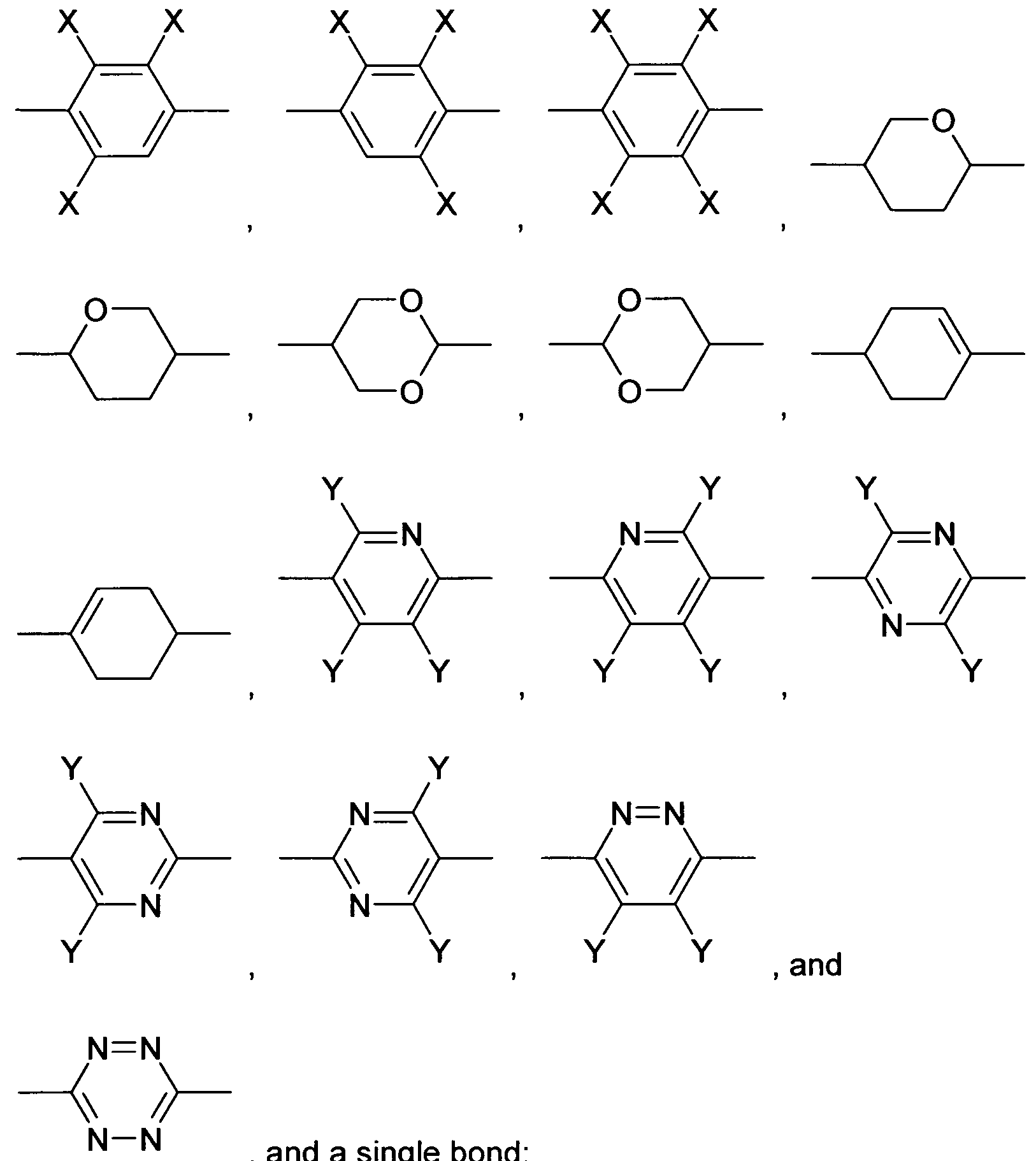
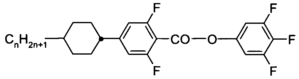
- X is on each occurrence, identically or differently, F, CI, Br, CN or an alkyl, alkoxy or thioalkoxy group having 1 to 10 C atoms, where one or more H atoms in the groups mentioned above may be replaced by F or CI and where one or more CH 2 groups may be replaced by O or S; and
- Y is on each occurrence, identically or differently, selected from H and X;
- Z 1 and Z 12 are, identically or differently, selected from CO-0-, -0-CO-, -CF 2 0-, -OCF 2 -, -OCH 2 -, -CH 2 0-, -CH 2 CH 2 - and a single bond.
- the liquid-crystalline medium furthermore comprises one or more compounds of the formula (II)
- formula (II) are on each occurrence, identically or differently, selected from H, F, CI, CN, NCS, R -0-CO-, R 1 -CO-O-, an alkyl, alkoxy or thioalkoxy group having 1 to 10 C atoms and an alkenyl, alkenyloxy or thioalkenyloxy group having 2 to 10 C atoms, where one or more H atoms in the groups mentioned above may be replaced by F or CI, and where one or more CH 2 groups in the groups mentioned above may be replaced by O, S, -O-CO- or -CO-0-;
- R is defined as above; are selected from
- Q Y is on each occurrence, identically or differently, selected from H and X;
- X is defined as above; and 5 Z 2 is selected from -CO-0-, -0-CO-, -CF 2 0-, -OCF 2 -, -CH 2 CH 2 -,
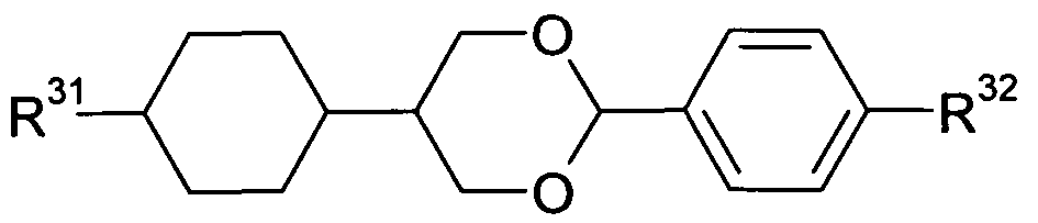
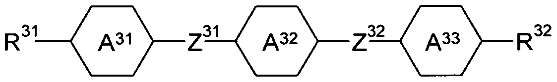
- the liquid-crystalline medium furthermore comprises one orQ more compounds selected from compounds of the formula (III)
- R 5 is H, CN, NCS, R 1 -0-CO-, R 1 -CO-0-, an alkyl, alkoxy or thioalkoxy group having 1 to 10 C atoms, or an alkenyl, alkenyloxy or thioalkenyloxy group having 2 to 10 C atoms, where one or more CH 2 groups in the groups mentioned above may be replaced by O, S, -O-CO- or -CO-0-; is H, an alkyl or alkoxy group having 1 to 10 C atoms, or an alkenyl or alkenyloxy group having 2 to 10 C atoms; and are on each occurrence, identically or differently, selected from
- Z 31 and Z 32 are, identically or differently, selected from CO-0-, -0-CO-, -CF 2 O- ( -OCF 2 -, -OCH 2 -, -CH 2 O-, -CH 2 CH 2 - and a single bond.
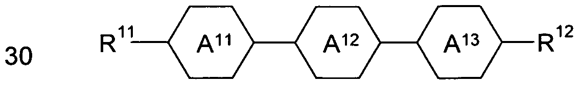
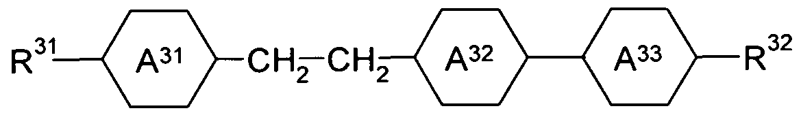
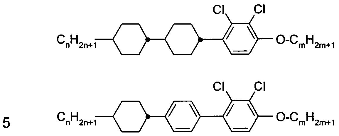
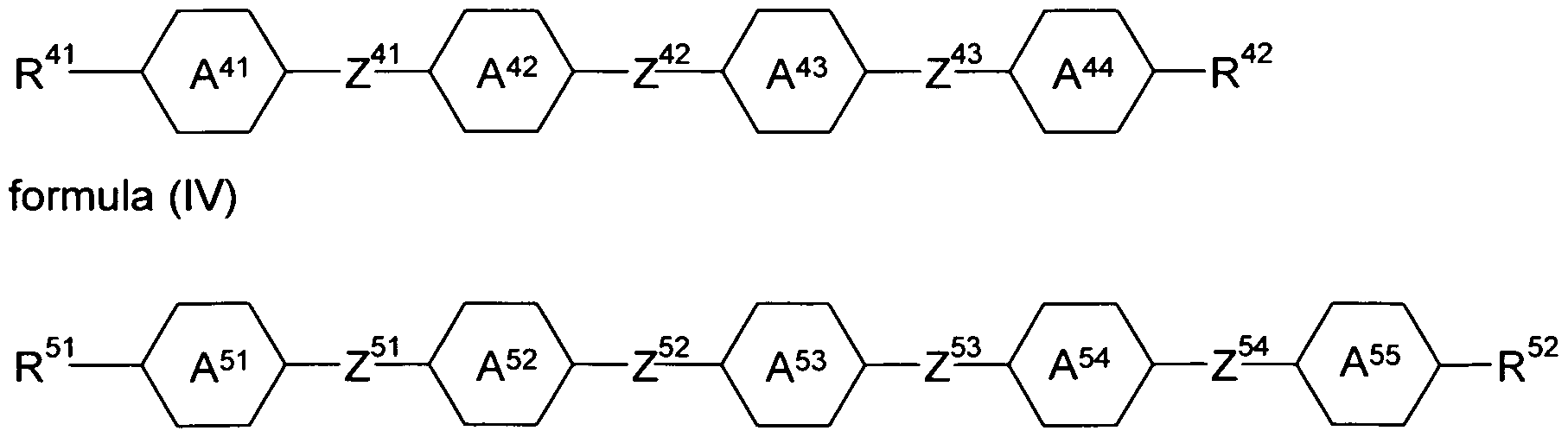
- the liquid-crystalline medium furthermore comprises one or more compounds selected from compounds of the formulas (IV), (V) and (VI)
- R 1 ,R 42 ,R 51 ,R 52 ,R 6 ,R 62 are on each occurrence, identically or differently, selected from H, F, CI, CN, NCS, R 1 -0-CO-, R 1 -CO-0-, an alkyl, alkoxy or thioalkoxy group having 1 to 10 C atoms and an alkenyl, alkenyloxy or thioalkenyloxy group having 2 to 10 C atoms, where one or more H atoms in the groups mentioned above may be replaced by F or CI, and where one or more CH 2 groups in the groups mentioned above may be replaced by O, S, -O-CO- or -CO-O-; is defined as above;
- Y is on each occurrence, identically or differently, selected from H and X;
- X is defined as above;
- Z 41 to Z 43 and Z 51 to Z 55 are, identically or differently, selected from -CO-O-, -O-CO-, -CF 2 O-, -OCF 2 -, -CH 2 CH 2 -, -OCH 2 -, -CH 2 O- and a single bond.
- the liquid-crystalline medium comprises one or more compounds of formula (I) and one or more compounds selected from compounds of the formulas (II), (III), (IV), (V) and (VI), as defined above. According to a particularly preferred
- the liquid-crystalline medium comprises one or more compounds of formula (I) and one or more compounds of formula (II). According to another particularly preferred embodiment, the liquid- crystalline medium comprises one or more compounds of formula (I) and one or more compounds of formula (VI).
- X is, identically or differently on each occurrence, selected from F, CI, CN and an alkyl or alkoxy group having 1 to 8 C atoms. It is particularly preferred that X is selected from F, CI, and an alkyl group having 1 to 8 C atoms, and it is very particularly preferred that X is F.
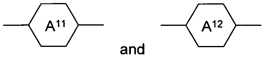
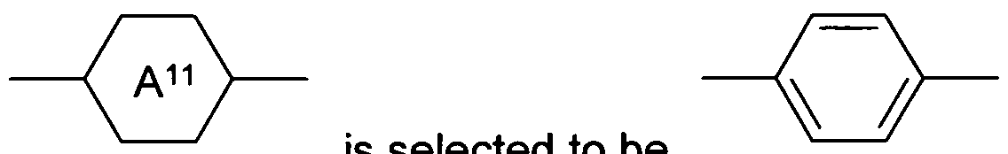
- compounds according to formula (I) are selected from compounds according to formulas (l-A) and (l-B),
- Z 11 and Z 12 are, identically or differently, selected from CO-0-, -0-CO-, -CF 2 0-, -OCF2-, -OCH2-, -CH2O-, -CH2CH2- and a single bond, with the proviso that at least one of Z 11 and Z 12 is not a single bond.
- R 11 is H, F, CI, CN, R 1 -O-CO-, R 1 -CO-0-, an alkyl or alkoxy group having 1 to 10 C atoms or an alkenyl or alkenyloxy group having 2 to 10 C atoms, where one or more H atoms in the groups mentioned above may be replaced by F or CI, and where one or more CH 2 groups in the groups mentioned above may be replaced by -O-CO- or -CO-O-, with R 1 being defined as above.
- R 12 is selected from F, CI, alkyl and alkoxy groups having 1 to 3 C atoms, and alkenyl and alkenyloxy groups having 2 to 3 C atoms, with the proviso that in the above-mentioned groups two or more H atoms are replaced by F.
- R 12 is selected from F or the following groups R 12"1 to R 12"38
- R 12-1 R 12-2 R 12-3 R 12-4 -OCHF2 -OCH2F -CHF-CF3 -CF2-CF3
- R 12 is particularly preferred to be F or OCF 3 .
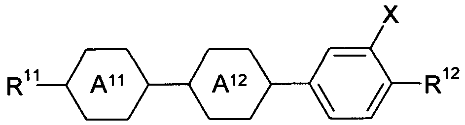
- Particularly preferred embodiments of compounds according to formula (l-A) are compounds of the following formulas (l-A-1) to (l-A-4)
- X is defined as above and is preferably, identically or differently, an alkyl group having 1 to 8 C atoms, F, or CI;
- R 11 is H, F, CI, CN, R 1 -O-CO-, R 1 -CO-0-, an alkyl or alkoxy group having 1 to 10 C atoms or an alkenyl or alkenyloxy group having 2 to 10 C atoms, where one or more H atoms in the groups mentioned above may be replaced by F or CI, and where one or more CH 2 groups in the groups mentioned above may be replaced by -O-CO- or -CO-0-, with R 1 being defined as above;
- R 12 is selected from F, CI, alkyl and alkoxy groups having 1 to 3 C atoms, and alkenyl and alkenyloxy groups having 2 to 3 C atoms, with the proviso that in the above-mentioned groups two or more H atoms are replaced by F; and
- Particularly preferred embodiments of compounds according to formula (l-A-1) are compounds of the following formulas (l-A-1a) to (l-A-1g)
- R 12 is selected from F and the above groups R 2"1 to R 12
- Particularly preferred embodiments of compounds according to formula (l-A-2) are compounds of the following formulas (l-A-2a) to (l-A-2g)
- R 12 is selected from F and the above groups R 12"1 to R 12
- Particularly preferred embodiments of compounds according to formula (l-A-3) are compounds of the following formulas (l-A-3a) to (l-A-3g)
- R 12 is defined as above, and R 12 is selected from F and the above groups R 12"1 to R 12"38 .
- Particularly preferred embodiments of compounds according to formula (l-A-4) are compounds of the following formulas (l-A-4a) to (l-A-4g)
- R 1 is defined as above, and
- R 12 is selected from F and the above groups R 12"1 to R 12"38 .
- exactly one of Z 1 and Z 12 is a single bond and the other is selected fin CO-O-, -0-CO-, -CF 2 0-, -OCF 2 -, -OCH 2 -, -CH 2 O- and -CH 2 CH 2 -.
- Z 11 is a single bond and Z 12 is selected from CO-O-, -O-CO-, -CF 2 O-, -OCF 2 -, -OCH 2 -, -CH 2 0- and -CH 2 CH 2 -.
- Preferred embodiments of compounds according to formula (l-B) are compounds according to the following formulas (l-B-1) to (l-B-14)
- R 11 is H, F, CI, CN, R 1 -0-CO-, R 1 -CO-0-, an alkyl or alkoxy group having 1 to 10 C atoms or an alkenyl or alkenyloxy group having 2 to 10 C atoms, where one or more H atoms in the groups mentioned above may be replaced by F or CI, and where one or more CH 2 groups in the groups mentioned above may be replaced by -O-CO- or -CO-O-, with R being defined as above;
- R 12 is selected from F, CI, alkyl and alkoxy groups having 1 to 3 C atoms, and alkenyl and alkenyloxy groups having 2 to 3 C atoms, with the proviso that in the above-mentioned groups two or more H atoms are replaced by F; and are, identically or differently, selected from
- X is defined as above and is preferably, identically or differently, F or CI.
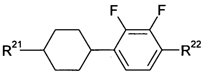
- R 21 is selected from H, an alkyl group having 1 to 10 C atoms and an alkenyl group having 2 to 10 C atoms, where one or more H atoms in the groups mentioned above may be replaced by F or CI.
- R is selected from H, F, CI, CN or an alkyl or alkoxy group having 1 to 10 C atoms and an alkenyl or alkenyloxy group having 2 to 10 C atoms, where one or more H atoms in the groups mentioned above may be replaced by F or CI.
- Z 21 is selected from -CO-0-, CH2CH2- and a single bond. According to a more preferred embodiment, Z 21 is a single bond.
- Preferred embodiments of compounds according to formula (II) are compounds of the following formulas (11-1) to (II-5)
- R 2 is H, an alkyl group having 1 to 10 C atoms or an alkenyl group having 2 to 10 C atoms;
- R 22 is H, an alkyl group having 1 to 10 C atoms or an alkenyl group having 2 to 10 C atoms, where one or more H atoms may be replaced by F or CI.
- R 21 and R 22 are, identically or differently, H, an alkyl group having 1 to 10 C atoms or an alkenyl group having 2 to 10 C atoms.
- Most preferred embodiments of compounds according to formula (11-3) are compounds of the following formulas (ll-3a) and (ll-3b)
- R 21 is H, an alkyl group having 1 to 10 C atoms or an alkenyl group having 2 to 10 C atoms.
- R is H, an alkyl group having 1 to 10 C atoms or an alkenyl group having 2 to 10 C atoms.
- R 21 and R 22 are, identically or differently, H, an alkyl group having 1 to 10 C atoms or an alkenyl group having 2 to 10 C atoms.
- compounds according to formula (III) are compounds according to formula (lll-A) or (lll-B)
- R 31 is H, CN, NCS, R 1 -0-CO-, R 1 -CO-0-, an alkyl, alkoxy or thioalkoxy group having 1 to 10 C atoms, or an alkenyl, alkenyloxy or thioalkenyloxy group having 2 to 10 C atoms, where one or more CH 2 groups in the groups mentioned above may be replaced by O, S, -O-CO- or -CO-O-, with R 1 being defined as above;
- R 32 is H, an alkyl or alkoxy group having 1 to 10 C atoms or an alkenyl or alkenyloxy group having 2 to 10 C atoms;
- Z 3 and Z 32 are, identically or differently, selected from CO-O-, -O-CO-, -CF 2 O-, -OCF2-, -OCH 2 -, -CH 2 O-, -CH 2 CH 2 - and a single bond, with the proviso that at least one of Z 31 and Z 32 is not a single bond; and are defined as above.
- R 31 is CN, R -O-CO-, R -CO-0-, an alkyl or alkoxy group having 1 to 10 C atoms or an alkenyl or alkenyloxy group having 2 to 10 C atoms, where one or more CH 2 groups in the groups mentioned above may be replaced by -O-CO- or -CO-O-, with R 1 being defined as above.
- compounds according to formula (lll-A) are compounds of the following formulas (lll-A-1) to (lll-A-3)
- X being defined as above and preferably being F.
- Particulary preferred compounds according to formula (lll-A) according to this preferred embodiment are compounds of the formulas (lll-A-4) to (lll-A-11)
- R 31 is selected from H, alkyl groups having 1 to 10 C atoms, or alkenyl groups having 2 to 10 C atoms;
- R is selected from H, alkyl or alkoxy groups having 1 to 10 C atoms, or alkenyl or alkenyloxy groups having 2 to 10 C atoms.
- exactly one of Z 31 and Z 32 is a single bond and the other is selected from CO-0-, -0-CO-, -CF 2 0-, -OCF 2 -, -OCH 2 -, -CH 2 O- and -CH 2 CH 2 -.
- Z 31 is a single bond and Z 32 is selected from CO-O-, -O-CO-, -CF 2 0-, -OCF 2 -, -OCH 2 -, -CH 2 O- and -CH 2 CH 2 -.
- X is defined as above and is preferably F.
- Preferred embodiments of compounds according to formula (lll-B) are compounds of the formulas (lll-B-1) to (lll-B-14)
- X is defined as above and is preferably F
- concentration of the compounds of the formula (I) is between 5 and 100 %. More preferably, the concentration of the compounds according to formula (I) is between 10 and 98 %, most preferably between 20 and 97 %.
- the total concentration of the compounds of the formula (l-A) is between 5 and
- the concentration of the compounds according to formula (l-A) is between 10 and 98 %, most preferably between 20 and
- the total concentration of the compounds of the formulas (l-A-2) and (l-A-3) is between 5 and 100 %. More preferably, the concentration of the
- the total concentration of the compounds of formula (II) is between 0 and 60 %. More preferably, the concentration of the compounds according to formula (II) is between 0 and 55 %. it is furthermore preferred that the total concentration of the compounds of the formulas (I) and (II) is between 20 and 100 %. More preferably, the concentration of the compounds according to formulas (I) and (II) is between 30 and 100 %, most preferably between 40 and 100 %. it is furthermore preferred that the total concentration of the compounds of the formulas (I) and (VI) is between 10 and 100 %, more preferably 20 to 100 % and most preferably 40 to 100 %.
- the total concentration of the compounds of the formula (III) is between 0 and 70 %. More preferably, the total concentration of the compounds of the formula (III) is between 0 and 60 %. Most preferably, it is between 0 and 50 %.
- the total concentration of the compounds of the formulas (IV) and (V) is between 0 and 40 %.
- the total concentration of the compounds of the formula (VI) is between 0 and 60 %.
- the invention concerns furthermore a liquid-crystalline medium comprising one or more compounds of the formula (I) as defined above in a total concentration of 5 to 100 %, and preferably at least one further compound of the formulas (II) and (III) as defined above, so that the total
- concentration of the compounds of the formulas (I), (II) and (III) is between 20 and 100 %.
- the liquid-crystalline medium comprises at least 5 different compounds selected from the compounds of formulas (I) to (VI).
- the liquid-crystalline medium comprises at least 6 different compounds selected from the compounds of formulas (I) to (VI).
- the liquid-crystalline medium comprises at least 7 different compounds selected from the compounds of formulas (I) to (VI).
- the media according to the present invention may comprise further liquid crystal compounds in order to adjust the physical properties. Such compounds are known to the expert. Their concentration in the media according to the instant invention is preferably 0 % to 30 %, more preferably 0.1 % to 20 % and most preferably 1 % to 15 %.
- the liquid crystal media according to the present invention may contain chiral dopants as further additives in usual concentrations.
- Preferred chiral dopants are listed in Table E below.
- the total concentration of these further constituents is in the range of 0 % to 10 %, preferably 0.1 % to 6 %, based on the total mixture.
- the concentrations of the individual compounds used each are preferably in the range of 0.1 % to 3 %. The concentration of these and of similar additives is not taken into
- the liquid crystalline media according to the invention may contain stabilizers as further additives in usual concentrations.
- Preferred stabilizers are listed in Table F below.
- the total concentration of the stabilizers is in the range of 0 % to 10 %, preferably 0.0001 % to 1 %, based on the total mixture.
- the clearing point (the temperature of the phase transition from the nematic to the isotropic state, T(N,I)) is lower than 60 °C. According to a particularly preferred embodiment, T(N,I) is lower than 50 °C. According to an even more preferred embodiment, T(N,I) is lower than 40 °C.
- the liquid crystal media according to the present invention consist of several compounds, preferably of 5 to 30, more preferably of 6 to 20 and most preferably of 6 to 16 compounds. These compounds are mixed according to methods known in the art. As a rule, the required amount of the compound used in the smaller amount is dissolved in the compound used in the greater amount. In case the temperature is above the clearing point of the compound used in the higher concentration, it is particularly easy to observe completion of the process of dissolution. It is, however, also possible to prepare the media by other conventional ways, e.g. using so called pre-mixtures, which can be e.g. homologous or eutectic mixtures of compounds or using so called multi-bottle-systems, the constituents of which are ready to use mixtures themselves.
- pre-mixtures which can be e.g. homologous or eutectic mixtures of compounds or using so called multi-bottle-systems, the constituents of which are ready to use mixtures themselves.
- the invention concerns furthermore a process for the preparation of a liquid-crystalline medium as defined above, characterized in that one or more compounds according to formula (I) and one or more compounds according to formulas (II) to (VI) are mixed with one another and optionally with one or more further mesogenic compounds and/or additives.
- the switch element comprises
- polarisers preferably in the form of thin layers, one of them positioned on one side of the liquid-crystalline medium, the other positioned on the opposite side of the liquid-crystalline medium.
- the polarisers can be linear or circular polarisers, preferably linear polarisers.
- the directions of polarisation of the two polarisers are rotated with respect to each other by a defined angle.
- Further layers and/or elements such as one or more separate alignment layers, one or more glass sheets, one or more bandblock filters and/or color filters to block light of certain wavelengths, for example UV-light, may be present.
- one or more insulating layers such as low- emissivity films, for example, may be present.
- one or more adhesive layers, one ore more protective layers, one or more passivation layers and one or more barrier layers may be present.
- a metal oxide layer where the metal oxide may comprise two or more different metals and where the metal oxide may be doped with halogenide ions, preferably fluoride, may be present.
- a metal oxide layer comprising one or more of the following: indium tin oxide (ITO), antimony tin oxide (ATO), aluminium zinc oxide (AZO), SnO 2 and SnO 2 :F (fluorine doped SnO 2 ).
- ITO indium tin oxide
- ATO antimony tin oxide
- AZO aluminium zinc oxide
- SnO 2 and SnO 2 :F fluorine doped SnO 2
- a metal oxide layer comprising ITO.
- spacers may be present. Typical embodiments of the above-mentioned elements as well as their function is known to the person skilled in the art.
- polariser refers to a device or substance which blocks light of one polarisation direction and transmits light of another polarisation direction.
- polariser refers to a device or substance which blocks light of one kind of circular polarisation (right-handed or left-handed) whereas it transmits light of the other kind of circular polarisation (left-handed or right-handed).
- a reflective polariser therefore reflects light of one polarisation direction or one kind of circular polarisation and transmits light of the opposite polarisation direction or other kind of circular polarisation; and an absorptive polariser absorbs light of one polarisation direction or one kind of circular
- polarisation and transmits light of the opposite polarisation direction or other kind of circular polarisation.
- the reflection or absorption is typically not quantitative, leading to the polarisation of light by the polariser not being perfect.
- both absorptive and reflective polarisers may be used in the switch element.
- the polarisers according to the invention represent optical thin films.
- Examples of reflective polarisers which can be used according to the invention are DRPF (diffusive reflective polariser film, by 3M), DBEF (dual brightness enhanced film, by 3M), layered-polymer distributed Bragg reflectors (DBR) as described in US 7,038,745 and US 6,099,758 and APF (advanced polariser film, by 3M).
- wire-grid-polarisers (WGP) which reflect infrared light, as described in US 4,512,638, for example, may be used.
- Wire-grid polarizers which reflect in the visible and ultraviolet part of the spectrum are described in US 6,122,103, for example, and may also be used according to the invention.
- absorptive polarisers which may be used according to the invention are Itos XP38 polarising film or Nitto Denko GU-1220DUN polarising film.
- circular polarisers which can be used according to the invention are APNCP37- 035-STD (left handed) and APNCP37-035-RH (right handed) from
- the switch element is thermoresponsive, signifying that its switching state is determined by temperature.
- no electrical wiring, circuitry and/or switching network is present in the switch element. The switching of the switch element occurs between a bright or open state of the switch element in which a higher proportion of radiant energy is transmitted and a dark or shut state of the switch element in which a smaller proportion of radiant energy is transmitted.
- Radiant energy is defined as above and is understood to comprise electromagnetic radiation in the UV-A region, VIS region and near-infrared region.
- the switch element is not equally effective over the complete spectrum of radiant energy as defined above.
- the switch element blocks a high proportion of NIR and VIS-light in the shut state, particularly preferably a high proportion of NIR light.
- switch elements that switch in one of the ranges VIS or NIR only as well as combinations switching in one range and permanently blocking the other, for example switching VIS and permanently blocking NIR.
- the switching is effected by a change in the physical condition of the liquid-crystalline medium.
- This change in the physical condition of the liquid-crystalline medium is temperature-dependent. Preferably, it is a phase transition.
- the switching is effected by a phase transition of the liquid-crystalline medium from a liquid-crystalline phase to an isotropic phase which takes place at a particular temperature. Even more preferably, the switching is effected by a phase transition of the liquid-crystalline medium from a nematic phase to an isotropic phase.
- the liquid-crystalline medium is in the isotropic state at a temperature above the phase-transition temperature and in a liquid- crystalline, preferably nematic state at a temperature below the phase- transition temperature.
- the liquid- crystalline medium represents the thermoresponsive element of the optical switch.
- further thermoresponsive elements may be present.
- the switch For the use of the switch to regulate the radiation energy flow between an interior space and the environment, preferably between a room of a building and the exterior, it is desirable that the switch operates at a temperature which is typical for the exterior of buildings.
- the switching temperature of the switch element is between -20 and 80 °C, more preferably between 10 and 60 °C and most preferably between 20 and 50 °C.
- the switching temperature is defined to be the temperature of the switch element. Typically, this temperature is similar to the outside air
- the switching of the switch element is effected by a change in the physical condition of the liquid-crystalline medium. More preferably, this change in physical condition represents a phase transition which takes place at a certain phase transition temperature.
- the phase transition temperature is between -20 and 80 °C, more preferably between 10 and 60 °C and most preferably between 20 and 50 °C.
- the plane of polarisation of polarised light is rotated by the liquid-crystalline medium by a defined value if it is in the liquid-crystalline state.
- the plane of polarisation of polarised light is not rotated by the liquid-crystalline medium if it is in the isotropic state.
- the directions of polarisation of the polarisers are not identical to each other, but rotated against each other by a defined angle. ln this preferred embodiment, the two states of the device are
- incoming light is polarised linearly by the first polariser.
- the linearly polarised light then passes through the liquid- crystalline medium in its liquid-crystalline state, which leads to its direction of polarisation being rotated by a defined angle.
- the linearly polarised light After passing the liquid-crystalline medium, the linearly polarised light then hits the second polariser. A defined fraction of the light hitting the polariser is transmitted through the polariser.
- there is an identity or only a relatively small divergence most preferably an identity of the value by which the planes of polarisation of the two polarisers are rotated against each other and the value by which the plane of polarisation of the polarised light is rotated by the liquid-crystalline medium in its nematic state.
- the value by which the plane of polarisation of the polarised light is rotated by the liquid-crystalline medium is understood to be the angle formed between the plane of polarisation before entering the medium and the plane of polarisation after leaving the medium.
- This angle can in principle be between 0° and 180°.
- a turn by an angle X being larger than 180° is equivalent to a turn by X minus n * 180°, the integer n being chosen so that the resulting angle X' is in the range 0° ⁇ X' ⁇ 180°.
- the liquid-crystalline medium may cause a twisting of the plane of polarisation of the polarised light passing it which has an absolute value larger than 180°. Even a rotation by more than one complete turn (360°), for example 2 1 ⁇ 4 turns or 3 3 ⁇ 4 turns may occur according to the invention.
- the net value by which the plane of polarisation of polarised light is rotated from entering to leaving the liquid- crystalline medium is still in any case between 0° and 180°, as has been explained above.
- the angle by which the plane of polarisation is rotated may also be represented as ranging from -90° to 90°, negative values meaning right-turns, positive values meaning left-turns.
- the liquid-crystalline medium is in its liquid-crystalline state. Typically, this is the case at a temperature below the phase-transition temperature.
- the switch element is in the bright state, when it is at a temperature which is below the switching temperature.
- the liquid-crystalline medium In order for the dark transparent or shut state to occur, it is required that the liquid-crystalline medium is in the isotropic state.
- incoming light is again linearly polarised by the first polariser.
- the polarised light then passes through the liquid-crystalline medium being in its isotropic state.
- the liquid-crystalline medium in the isotropic state does not rotate the direction of polarisation of linearly polarised light.
- the linearly polarised light with its direction of polarisation maintained hits the second polariser.
- the direction of polarisation of the second polariser is, as described above, rotated with respect to the direction of polarisation of the first polariser, which is in this case, as explained above, also the direction of polarisation of the linearly polarised light hitting the second polariser.
- the liquid-crystalline medium in its isotropic state. Typically, this is the case at a temperature above the phase-transition temperature. Therefore, according to this preferred embodiment, the switch element is in the dark or shut state, when it is at a temperature which is above the switching temperature.
- the directions of polarisation of the two polarisers may be rotated with respect to each other by any arbitrary value, depending on the desired transmission of the switch element in the dark transparent state. Preferred values are in the range of 45° to 135°, more preferred 70° to 110°, most preferred 80° to 100°.
- the value by which the liquid-crystalline medium in its nematic state rotates the plane of polarisation of polarised light does not have to be identical to the value by which the directions of polarisation of the two polarisers are rotated with respect to each other.
- the values are similar, with a preferred deviation of very preferably less than 30° and most preferably less than 20°.
- the value by which the liquid-crystalline medium in its nematic state rotates the plane of polarisation of polarised light is preferably in the range of 0° to 360°. However, values of larger than 360° may also be present according to the invention.
- the setup described above is generally preferred.
- the flow of radiant energy is allowed since the switch element is in the open state. This leads to an increase in the heat uptake of the building, reducing heating costs.
- the switch element is in the shut state, limiting the flow of radiant energy into the building. This decreases unwanted heat uptake at high temperatures, reducing the costs for air conditioning.
- more or less light is transmitted through the switch element in the shut state. With perfect polarisers in a "crossed" position (direction of polarisation rotated by 90° against each other), no light is transmitted in the shut state. If the direction of
- the amount of light which is transmitted through the switch element in the open state depends, among other factors, on the efficiency of the polarisers and on the difference between the angle by which the liquid-crystalline medium rotates the direction of polarisation of linearly polarised light and the angle by which the directions of polarisation of the two polarisers are rotated against each other.
- the angle by which the liquid-crystalline medium rotates the direction of polarisation of linearly polarised light depends, among other factors, on the angle by which the liquid-crystalline medium rotates the direction of polarisation of linearly polarised light and the angle by which the directions of polarisation of the two polarisers are rotated against each other.
- the rejection of 50 % of the light is due to the fact that a perfect linear polariser rejects (by absorption or reflection) 50 % of incoming unpolarised light.
- the transmittance of light through the device can therefore be raised significantly if non-perfect polarisers are used, which may be desirable.
- numerous other combinations of polariser orientations and rotation of the direction of polarised light due to the liquid- crystal medium can be used within the present invention.
- liquid-crystalline medium which scatters light when it is within a first temperature range and which is transparent within a second temperature range, whereas this second temperature range may be above or below the first temperature range.
- the liquid-crystalline medium may affect the polarisation state of circularly polarised light.
- the liquid- crystalline medium represents a guest-host system which comprises, in addition to one or more liquid-crystalline compounds, dye molecules or other materials which show absorptive or reflective properties.
- the liquid-crystalline medium provides orientation for the dye molecules when in the liquid-crystalline state (low temperature), but does not provide such orientation when in the isotropic state (high temperature).
- the guest-host-system shows temperature-dependent transmission properties.
- the liquid-crystalline medium represents a guest-host system
- a twisted nematic orientation of the liquid-crystalline medium or a vertically aligned orientation of the liquid-crystalline medium is preferably used.
- the rotation of polarised light by the liquid-crystalline medium in the liquid-crystalline state is caused by an alignment of the molecules of the liquid-crystalline medium.
- this alignment is typically effected by alignment layers which are in direct contact with the liquid-crystalline medium.
- the alignment layers represent the two outer boundaries of the liquid-crystalline medium layer.
- two alignment layers facing each other may be attached to the interior of the compartment enclosing the liquid-crystalline medium.
- the alignment layers constitute the compartment enclosing the liquid-crystalline medium.
- the alignment layers may be prepared by rubbing a polymer or polymer film with a rubbing cloth, a sandpaper or some other suitable material.
- Polyimide films are particularly suitable for this, but orientation may be achieved also on other kinds of polymers.
- the alignment layer and the polariser layer are not separate but form one single layer. They may, for example, be glued or laminated together. The property of inducing an alignment of the liquid-crystalline molecules may for example be conferred to the polariser by rubbing, scratching and/or micropatterning the polariser layer.
- patent application US 2010/0045924 whose disclosure is hereby incorporated by reference.
- a preferred embodiment of the switch element according to the invention comprises the liquid-crystalline medium within a container of transparent material, preferably a transparent polymer or glass.
- the switch element comprises two or more alignment layers which are in direct contact with the liquid-crystalline medium.
- the aligment layers can be attached to the inner surface of the above- mentioned container.
- the inner container surface can serve as an alignment layer itself.
- the switch element comprises two or more polarisers which may be present in the form of polarising foils, as disclosed above. Further rigid or flexible layers may be present, such as additional glass sheets, bandblock filters such as UV-blocking films and/or insulating layers such as low-emissivity films. According to this embodiment of the invention, the switch element is rigid and cannot be bent or rolled up for storage and/or transport due to the presence of layers of rigid material.
- the liquid- crystalline medium is enclosed by a flexible polymer sheet.
- This flexible polymer sheet may represent the polariser and/or the alignment layer. Further layers, such as described above, may be additionally present.
- the switch element is flexible and can be bent and/or rolled up.
- the liquid- crystalline medium has a solid or gel-like consistency.
- a rigid container for the liquid-crystalline medium is not required, eliminating the need for glass and/or rigid polymer sheets to be present in the switch element.
- An advantage of this embodiment of the invention is that the switch element is less vulnerable to damage and can be produced in the form of thin flexible sheets which can be rolled up. The switch element can then be cut from this roll in any shape or size, which simplifies storage, transport and production of the device.
- the liquid-crystalline medium may, for example, be embedded in the form of discrete compartments such as microdroplets of liquid-crystalline medium, within an optically transparent medium.
- the optically transparent medium preferably is a polymeric material, particularly preferably an isotropic thermoplastic, duroplastic or elastomeric polymer.
- the polymeric material is a thermoplastic or elastomeric polymer.
- PDLC-films polymer dispersed liquid crystal
- NCAP films may be obtained by a process in which the encapsulating polymeric material, for example polyvinyl alcohol, the liquid-crystalline medium and a carrier material, such as water, are mixed thoroughly in a colloid mill.
- the carrier material is removed, for example by evaporation.
- a detailed procedure for the formation of NCAP-films is described in
- WO 89/06264 may be obtained by homogeneously mixing the liquid- crystalline medium with monomers and/or oligomers which will later react to the polymer matrix. After polymerisation, a phase separation is induced, in which compartments or microdroplets of liquid crystalline medium form, which are dispersed within the polymer matrix.
- the liquid-crystalline medium is present as a continuous phase within a polymer network (PN- systems).
- PN- systems polymer network
- the polymer network typically has a spongy structure, in which the liquid-crystalline medium can float freely. According to a preferred embodiment, it is formed by polymerisation of mono- or polyacrylate monomers.
- the liquid-crystalline medium is present in PN-systems in a percentage of more than 60 %, particularly preferably in a percentage of 70-95 %.
- the polymer network systems can be prepared by inducing a polymerisation reaction in a mixture comprising the liquid-crystalline medium and the respective monomers and/or oligomers which form the three-dimensional polymer network. According to a preferred embodiment, the polymerisation is started by photoinitiation.
- the polymer does not form a network, but is dispersed in the form of small particles within the liquid-crystalline medium, which is present as a continuous phase as in PN-network systems.
- liquid-crystalline media according to the present invention are particularly suitable for use in the above-mentioned PDLC-, NCAP- and PN-systems. Further subject of the present invention is therefore a composite system comprising a liquid-crystalline medium as defined above and a polymer, preferably a microporous polymer.
- the switch element can be attached to transparent windows, facades, doors or roofs of any kind, including those present in private, public and commercial builings, in containers for transport, storage and inhabitation and in any vehicles. Particularly preferred is the attachment to insulated glass units (IGU) or multipane windows and/or the use as an integrated element of insulated glass units or multipane windows.
- IGU insulated glass units
- the switch element is attached at the outside-facing side of the window, facade, door or roof.
- the switch element is placed in the interior of an IGU, where it is protected from adverse effects such as extreme weather conditions and from degradation due to UV exposure.
- the switch element is attached at the inside-facing side of the window, facade, door or roof.
- the switch element covers the complete surface of the window. In this case, the control over the radiant energy flow by the switching of the device is maximised.
- the switch element covers only parts of the surface of the window, so that there are gaps left which are not covered by the switch element. These gaps may take the form of stripes, spots and/or larger areas. This could allow that some parts of a window can be switched between a bright state and a dark state, whereas other parts remain bright at all times. This leads to the
- the switch element may be used according to the invention to regulate the radiant energy flow between an interior space and the environment.
- the switch element regulates the radiant energy flow automatically, without the need for manual controlling, by its capability of temperature- dependent switching between an open state and a shut state.
- the switch element is used to regulate the interior temperature of a building and/or a vehicle.
- clearing points of a mixture in a display can be determined in normally white-mode TN-cells in a microscope hot stage. The beginning of the transition from the nematic to the isotropic state leads to black spots in the TN-cell. When heating up, the temperature at which such spots first occur is determined to be the clearing point.
- the liquid-crystalline mixture is filled into several TN-cells with a thickness of 5 to 6 pm.
- the TN-cells receive an end-seal, get polarisers attached for normally white mode setup and are stored for up to 1000 hours in a refrigerator at a given temperature.
- the TN-cells are inspected visually for dark spots indicating crystallisation or smectic- nematic transitions. If the TN-cells do not show spots at the end of the testing period, the test is passed. Otherwise, the time elapsed until the first spots are detected is noted as a measure of long-term storage stability.
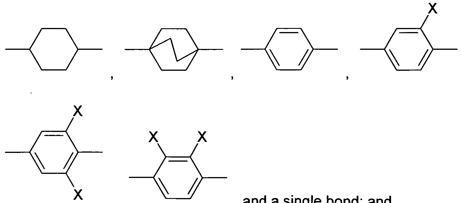
- the Indices n, m, p and q preferably have a value between 1 and 10. Remark: From left side to right side in the chemical structure, the indices used are n, if only one index occurs; n and m if two indices occur; n, m and p if three indices occur; and n, m, p and q if four indices occur. This nomenclature may be extended if necessary.
- a right-hand-side alkyl group -C n H2n+i corresponding to -n may also be a group -C m H 2m +i corresponding to -m, or a group -CpH 2 p + i corresponding to -p, or a group -C q H 2 q + i corresponding to -q, depending on the index which is chosen.
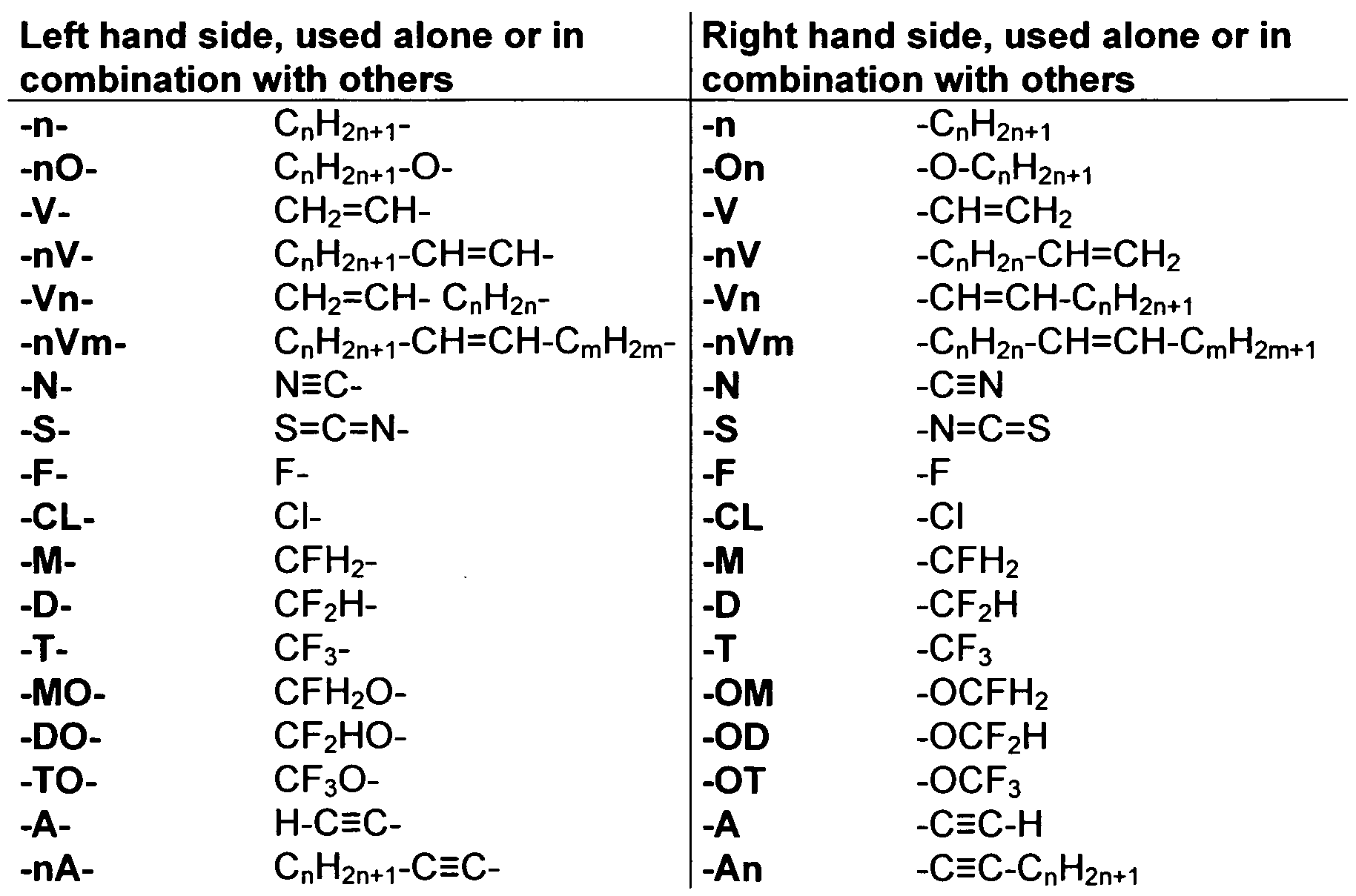
- Table C where a letter n is used signifying an alkyl group having n carbon atoms and 2n+1 hydrogen atoms or an alkylene group having n carbon atoms and 2n hydrogen atoms.
- Table A lists the symbols used for the ring elements, table B those for the linking groups and table C those for the symbols for the left hand and the right hand end groups of the molecules.
- n und m each are integers and three points indicate that other symbols of this table may be present at the position.
- Table E lists chiral dopants, which are preferably used in the liquid crystalline media according to the present invention.
- the media according to the present invention comprise one or more compounds selected from the group of compounds of table E.
- Table F lists stabilizers, which are preferably used in the liquid crystalline media according to the present invention.
- n means an integer in the range from 1 to 12.
- the media according to the present invention comprise one or more compounds selected from the group of compounds of table F.
- Liquid crystal mixtures with the compositions listed in the following tables are prepared, and their clearing points and long-term-storage behaviour are determined.
- the clearing point of the liquid-crystalline media according to the invention is preferably between -20 and 80 °C, more preferably between 10 and 60 °C and most preferably between 20 and 50 °C. Even more preferably, the clearing point is between 20 and 40 C°.
- Exemplary mixtures with a relatively high clearing point are preferably used as a so-called two-bottle system in combination with a mixture having a lower clearing point.
- mixtures 1 to 14 according to the invention are employed as liquid- crystalline media in the switch element according to the procedure of US 2009/0015902.
- switch elements With the mixtures according to the invention (Example-1 to Example-14), switch elements with high operational lifetime can be obtained.
- the switch elements have a switching temperature which is close to the clearing point of the mixtures (10 °C to 80 °C, which is in the preferred operating range of the elements).
Abstract
Description


Claims


Priority Applications (5)
| Application Number | Priority Date | Filing Date | Title |
|---|---|---|---|
| EP11758413.6A EP2630217B1 (en) | 2010-10-20 | 2011-09-21 | Switch element comprising a liquid-crystalline medium |
| KR1020137012641A KR101879889B1 (en) | 2010-10-20 | 2011-09-21 | Switch element comprising a liquid-crystalline medium |
| US13/878,646 US9238775B2 (en) | 2010-10-20 | 2011-09-21 | Switch element comprising a liquid-crystalline medium |
| JP2013534183A JP5964310B2 (en) | 2010-10-20 | 2011-09-21 | Switch element including liquid crystal medium |
| CN201180050410.1A CN103180409B (en) | 2010-10-20 | 2011-09-21 | Switch element comprising liquid-crystalline medium |
Applications Claiming Priority (4)
| Application Number | Priority Date | Filing Date | Title |
|---|---|---|---|
| EP10013797 | 2010-10-20 | ||
| EP10013797.5 | 2010-10-20 | ||
| US40874910P | 2010-11-01 | 2010-11-01 | |
| US61/408,749 | 2010-11-01 |
Publications (1)
| Publication Number | Publication Date |
|---|---|
| WO2012052100A1 true WO2012052100A1 (en) | 2012-04-26 |
Family
ID=44658713
Family Applications (1)
| Application Number | Title | Priority Date | Filing Date |
|---|---|---|---|
| PCT/EP2011/004731 WO2012052100A1 (en) | 2010-10-20 | 2011-09-21 | Switch element comprising a liquid-crystalline medium |
Country Status (8)
| Country | Link |
|---|---|
| US (1) | US9238775B2 (en) |
| EP (1) | EP2630217B1 (en) |
| JP (1) | JP5964310B2 (en) |
| KR (1) | KR101879889B1 (en) |
| CN (1) | CN103180409B (en) |
| PL (1) | PL2630217T3 (en) |
| TW (1) | TWI542674B (en) |
| WO (1) | WO2012052100A1 (en) |
Cited By (12)
| Publication number | Priority date | Publication date | Assignee | Title |
|---|---|---|---|---|
| WO2013060406A1 (en) | 2011-10-24 | 2013-05-02 | Merck Patent Gmbh | Switch element comprising a liquid crystalline medium |
| WO2014090373A1 (en) | 2012-12-13 | 2014-06-19 | Merck Patent Gmbh | Liquid-crystalline medium |
| WO2014135240A2 (en) | 2013-03-05 | 2014-09-12 | Merck Patent Gmbh | Device for regulating the passage of energy |
| WO2014180525A1 (en) | 2013-05-08 | 2014-11-13 | Merck Patent Gmbh | Device comprising two liquid crystal switching layers for regulating the passage of optical energy |
| WO2014187529A1 (en) | 2013-05-24 | 2014-11-27 | Merck Patent Gmbh | Device for controlling the passage of energy, containing a dichroic dye compound |
| WO2016173693A1 (en) | 2015-04-27 | 2016-11-03 | Merck Patent Gmbh | Optical switching layer for use in an optical switching element |
| WO2017118465A1 (en) * | 2016-01-06 | 2017-07-13 | Merck Patent Gmbh | Device for regulating entry of light |
| EP3260913A1 (en) | 2016-06-22 | 2017-12-27 | Merck Patent GmbH | Optical switching device |
| WO2019110458A1 (en) * | 2017-12-06 | 2019-06-13 | Merck Patent Gmbh | Liquid-crystalline medium for use in a switching element |
| EP3623451A1 (en) | 2013-12-19 | 2020-03-18 | Merck Patent GmbH | Compound |
| WO2020127141A1 (en) * | 2018-12-19 | 2020-06-25 | Merck Patent Gmbh | Switching layers for use in a switching element |
| WO2020229434A1 (en) * | 2019-05-15 | 2020-11-19 | Merck Patent Gmbh | Method for preparing a liquid crystal-based switching element |
Families Citing this family (25)
| Publication number | Priority date | Publication date | Assignee | Title |
|---|---|---|---|---|
| CN102858917B (en) * | 2010-04-28 | 2015-02-18 | 默克专利股份有限公司 | Optical switch element comprising a liquid-crystalline medium |
| WO2011144299A1 (en) * | 2010-05-19 | 2011-11-24 | Merck Patent Gmbh | Optical switch element comprising a liquid-crystalline medium |
| GB201009488D0 (en) * | 2010-06-07 | 2010-07-21 | Merck Patent Gmbh | Switch element comprising a liquid-crystaline medium |
| EP2423294A1 (en) * | 2010-08-24 | 2012-02-29 | Merck Patent GmbH | Switch element comprising a liquid-crystalline medium |
| CN102337139A (en) * | 2011-08-02 | 2012-02-01 | 江苏和成化学材料有限公司 | Liquid crystal composition and liquid crystal display comprising same |
| CN108251127A (en) * | 2014-11-20 | 2018-07-06 | 北京八亿时空液晶科技股份有限公司 | Liquid crystal compound containing difluoromethoxy bridge bond and application thereof |
| CN104479688B (en) * | 2014-11-27 | 2016-06-29 | 北京八亿时空液晶科技股份有限公司 | A kind of containing the liquid-crystal compounds of difluoro-methoxy bridged bond, compositions and application thereof |
| CN104610983B (en) * | 2015-01-21 | 2017-01-11 | 北京八亿时空液晶科技股份有限公司 | Liquid crystal composition containing 2-methyl-3,4,5-trifluorobenzene liquid crystal compound and application of liquid crystal composition |
| CN104673323B (en) * | 2015-02-04 | 2016-09-21 | 北京八亿时空液晶科技股份有限公司 | A kind of liquid-crystal composition containing 2-methyl-3,4,5-trifluoro-benzene liquid-crystal compounds and application thereof |
| CN104774623B (en) * | 2015-03-13 | 2017-03-01 | 北京八亿时空液晶科技股份有限公司 | A kind of liquid-crystal composition and its application |
| CN104830349B (en) * | 2015-03-13 | 2017-03-29 | 北京八亿时空液晶科技股份有限公司 | Liquid-crystal composition containing 2 methyl, 3,4,5 trifluoro-benzene liquid-crystal compoundss and its application |
| CN106065329B (en) * | 2015-04-28 | 2018-03-30 | 北京八亿时空液晶科技股份有限公司 | A kind of liquid-crystal compounds containing difluoro-methoxy bridged bond, composition and its application |
| CN107557020A (en) * | 2015-09-02 | 2018-01-09 | 石家庄诚志永华显示材料有限公司 | A kind of liquid-crystal compounds and its preparation method and application |
| CN105112073A (en) * | 2015-09-21 | 2015-12-02 | 西安近代化学研究所 | Negative nitrogen heterocyclic liquid crystal compound and liquid crystal composition |
| CN105295950A (en) * | 2015-09-30 | 2016-02-03 | 石家庄诚志永华显示材料有限公司 | Liquid crystal medium containing light absorbing agent and triphenyl series liquid crystal compounds |
| CN105295956A (en) * | 2015-09-30 | 2016-02-03 | 石家庄诚志永华显示材料有限公司 | Positive dielectric liquid crystal composition |
| CN105295955A (en) * | 2015-09-30 | 2016-02-03 | 石家庄诚志永华显示材料有限公司 | Positive and negative mixed liquid crystal composition |
| CN105199746A (en) * | 2015-09-30 | 2015-12-30 | 石家庄诚志永华显示材料有限公司 | Liquid crystal composition with high UV (ultraviolet) stability |
| CN105199745A (en) * | 2015-09-30 | 2015-12-30 | 石家庄诚志永华显示材料有限公司 | Positive-negative-mixed liquid crystal composition |
| CN105419816A (en) * | 2015-12-07 | 2016-03-23 | 石家庄诚志永华显示材料有限公司 | Liquid crystal medium and liquid crystal display including same |
| KR20180099870A (en) * | 2016-01-06 | 2018-09-05 | 메르크 파텐트 게엠베하 | Liquid crystal mixture |
| CN105694909B (en) * | 2016-01-13 | 2018-08-28 | 石家庄诚志永华显示材料有限公司 | Liquid-crystal composition |
| CN108300488A (en) * | 2017-10-31 | 2018-07-20 | 晶美晟光电材料(南京)有限公司 | A kind of low diffusivity liquid crystal compound and its application |
| CN109134423B (en) * | 2017-11-23 | 2020-03-17 | 江苏和成显示科技有限公司 | Compound, liquid crystal composition thereof and photoelectric display device |
| KR20200093633A (en) * | 2017-12-06 | 2020-08-05 | 메르크 파텐트 게엠베하 | Liquid crystal medium for use in switching elements |
Citations (26)
| Publication number | Priority date | Publication date | Assignee | Title |
|---|---|---|---|---|
| US3990784A (en) | 1974-06-05 | 1976-11-09 | Optical Coating Laboratory, Inc. | Coated architectural glass system and method |
| US4268126A (en) | 1978-12-20 | 1981-05-19 | Allied Chemical Corporation | Thermal-pane window with liquid crystal shade |
| US4435047A (en) | 1981-09-16 | 1984-03-06 | Manchester R & D Partnership | Encapsulated liquid crystal and method |
| US4512638A (en) | 1982-08-31 | 1985-04-23 | Westinghouse Electric Corp. | Wire grid polarizer |
| US4641922A (en) | 1983-08-26 | 1987-02-10 | C-D Marketing, Ltd. | Liquid crystal panel shade |
| US4688900A (en) | 1984-03-19 | 1987-08-25 | Kent State University | Light modulating material comprising a liquid crystal dispersion in a plastic matrix |
| EP0272585A2 (en) | 1986-12-23 | 1988-06-29 | Asahi Glass Company Ltd. | Liquid crystal optical device and process for its production. |
| EP0313053A2 (en) | 1987-10-20 | 1989-04-26 | Dainippon Ink And Chemicals, Inc. | Liquid crystal device |
| WO1989006264A1 (en) | 1987-12-28 | 1989-07-13 | Hughes Aircraft Company | Dispersion of liquid crystal droplets in a photopolymerized matrix, and devices made therefrom |
| EP0359146A2 (en) | 1988-09-08 | 1990-03-21 | Dainippon Ink And Chemicals, Inc. | Liquid crystal device |
| EP0452460A1 (en) | 1989-10-02 | 1991-10-23 | Merck Patent Gmbh | Electro-optical liquid crystal system. |
| US5940150A (en) | 1991-11-27 | 1999-08-17 | Reveo, Inc. | Electro-optical glazing structures having total-reflection and transparent modes of operation for use in dynamical control of electromagnetic radiation |
| US6099758A (en) | 1997-09-17 | 2000-08-08 | Merck Patent Gesellschaft Mit Beschrankter Haftung | Broadband reflective polarizer |
| US6122103A (en) | 1999-06-22 | 2000-09-19 | Moxtech | Broadband wire grid polarizer for the visible spectrum |
| US6218018B1 (en) | 1998-08-21 | 2001-04-17 | Atofina Chemicals, Inc. | Solar control coated glass |
| EP1333082A1 (en) * | 2002-02-05 | 2003-08-06 | MERCK PATENT GmbH | Liquid crystalline medium with higher double refraction and improved UV stability |
| US20030197154A1 (en) * | 2002-04-16 | 2003-10-23 | Merck Paptentgesellschaft Mit Beschrankter Haftung | Liquid-crystalline medium having high birefringence and light stability |
| DE10317295A1 (en) * | 2002-04-16 | 2003-10-30 | Merck Patent Gmbh | Liquid crystal medium, useful for the production of liquid crystal display devices, contains a trifluoromethoxy aromatic compound |
| DE102004019901A1 (en) * | 2003-04-23 | 2004-11-18 | Merck Patent Gmbh | Liquid crystalline medium for electro-optical displays, e.g. TN-TFT and IPS displays, contains two groups of LC compounds with high dielectric anisotropy, plus LC compounds with low dielectric anisotropy and optionally others |
| US7038745B2 (en) | 1993-12-21 | 2006-05-02 | 3M Innovative Properties Company | Brightness enhancing reflective polarizer |
| WO2008027031A2 (en) | 2006-08-29 | 2008-03-06 | Jiuzhi Xue | Windows with electrically controllable transmission and reflection |
| US20080083903A1 (en) * | 2006-10-05 | 2008-04-10 | Chisso Corporation | Liquid crystal composition and liquid crystal display device |
| US20090015902A1 (en) | 2007-07-11 | 2009-01-15 | Powers Richard M | Thermally Switched Reflective Optical Shutter |
| US20090167971A1 (en) | 2007-12-20 | 2009-07-02 | Ravenbrick, Llc | Thermally switched absorptive window shutter |
| US20100045924A1 (en) | 2008-08-20 | 2010-02-25 | Ravenbrick, Llc | Methods for Fabricating Thermochromic Filters |
| US20100243956A1 (en) * | 2007-10-05 | 2010-09-30 | Merck Patent Gesellschaft Mit Beschrankter Haftung | Liquid-crystalline medium and liquid-crystal display |
Family Cites Families (8)
| Publication number | Priority date | Publication date | Assignee | Title |
|---|---|---|---|---|
| JP3807454B2 (en) * | 1995-12-27 | 2006-08-09 | チッソ株式会社 | Electro-optic liquid crystal system |
| JP3477980B2 (en) * | 1996-02-29 | 2003-12-10 | チッソ株式会社 | Liquid crystal composition and liquid crystal display device |
| JP4665265B2 (en) * | 1999-07-01 | 2011-04-06 | Dic株式会社 | Nematic liquid crystal composition and liquid crystal display device using the same |
| KR101182931B1 (en) | 2003-07-11 | 2012-09-13 | 메르크 파텐트 게엠베하 | Liquid-crystal medium containing monofluoroterphenyl compounds |
| CN102858917B (en) * | 2010-04-28 | 2015-02-18 | 默克专利股份有限公司 | Optical switch element comprising a liquid-crystalline medium |
| WO2011144299A1 (en) * | 2010-05-19 | 2011-11-24 | Merck Patent Gmbh | Optical switch element comprising a liquid-crystalline medium |
| GB201009488D0 (en) * | 2010-06-07 | 2010-07-21 | Merck Patent Gmbh | Switch element comprising a liquid-crystaline medium |
| EP2423294A1 (en) * | 2010-08-24 | 2012-02-29 | Merck Patent GmbH | Switch element comprising a liquid-crystalline medium |
-
2011
- 2011-09-21 PL PL11758413T patent/PL2630217T3/en unknown
- 2011-09-21 CN CN201180050410.1A patent/CN103180409B/en active Active
- 2011-09-21 US US13/878,646 patent/US9238775B2/en not_active Expired - Fee Related
- 2011-09-21 WO PCT/EP2011/004731 patent/WO2012052100A1/en active Application Filing
- 2011-09-21 KR KR1020137012641A patent/KR101879889B1/en active IP Right Grant
- 2011-09-21 EP EP11758413.6A patent/EP2630217B1/en active Active
- 2011-09-21 JP JP2013534183A patent/JP5964310B2/en not_active Expired - Fee Related
- 2011-10-19 TW TW100137951A patent/TWI542674B/en active
Patent Citations (26)
| Publication number | Priority date | Publication date | Assignee | Title |
|---|---|---|---|---|
| US3990784A (en) | 1974-06-05 | 1976-11-09 | Optical Coating Laboratory, Inc. | Coated architectural glass system and method |
| US4268126A (en) | 1978-12-20 | 1981-05-19 | Allied Chemical Corporation | Thermal-pane window with liquid crystal shade |
| US4435047A (en) | 1981-09-16 | 1984-03-06 | Manchester R & D Partnership | Encapsulated liquid crystal and method |
| US4512638A (en) | 1982-08-31 | 1985-04-23 | Westinghouse Electric Corp. | Wire grid polarizer |
| US4641922A (en) | 1983-08-26 | 1987-02-10 | C-D Marketing, Ltd. | Liquid crystal panel shade |
| US4688900A (en) | 1984-03-19 | 1987-08-25 | Kent State University | Light modulating material comprising a liquid crystal dispersion in a plastic matrix |
| EP0272585A2 (en) | 1986-12-23 | 1988-06-29 | Asahi Glass Company Ltd. | Liquid crystal optical device and process for its production. |
| EP0313053A2 (en) | 1987-10-20 | 1989-04-26 | Dainippon Ink And Chemicals, Inc. | Liquid crystal device |
| WO1989006264A1 (en) | 1987-12-28 | 1989-07-13 | Hughes Aircraft Company | Dispersion of liquid crystal droplets in a photopolymerized matrix, and devices made therefrom |
| EP0359146A2 (en) | 1988-09-08 | 1990-03-21 | Dainippon Ink And Chemicals, Inc. | Liquid crystal device |
| EP0452460A1 (en) | 1989-10-02 | 1991-10-23 | Merck Patent Gmbh | Electro-optical liquid crystal system. |
| US5940150A (en) | 1991-11-27 | 1999-08-17 | Reveo, Inc. | Electro-optical glazing structures having total-reflection and transparent modes of operation for use in dynamical control of electromagnetic radiation |
| US7038745B2 (en) | 1993-12-21 | 2006-05-02 | 3M Innovative Properties Company | Brightness enhancing reflective polarizer |
| US6099758A (en) | 1997-09-17 | 2000-08-08 | Merck Patent Gesellschaft Mit Beschrankter Haftung | Broadband reflective polarizer |
| US6218018B1 (en) | 1998-08-21 | 2001-04-17 | Atofina Chemicals, Inc. | Solar control coated glass |
| US6122103A (en) | 1999-06-22 | 2000-09-19 | Moxtech | Broadband wire grid polarizer for the visible spectrum |
| EP1333082A1 (en) * | 2002-02-05 | 2003-08-06 | MERCK PATENT GmbH | Liquid crystalline medium with higher double refraction and improved UV stability |
| US20030197154A1 (en) * | 2002-04-16 | 2003-10-23 | Merck Paptentgesellschaft Mit Beschrankter Haftung | Liquid-crystalline medium having high birefringence and light stability |
| DE10317295A1 (en) * | 2002-04-16 | 2003-10-30 | Merck Patent Gmbh | Liquid crystal medium, useful for the production of liquid crystal display devices, contains a trifluoromethoxy aromatic compound |
| DE102004019901A1 (en) * | 2003-04-23 | 2004-11-18 | Merck Patent Gmbh | Liquid crystalline medium for electro-optical displays, e.g. TN-TFT and IPS displays, contains two groups of LC compounds with high dielectric anisotropy, plus LC compounds with low dielectric anisotropy and optionally others |
| WO2008027031A2 (en) | 2006-08-29 | 2008-03-06 | Jiuzhi Xue | Windows with electrically controllable transmission and reflection |
| US20080083903A1 (en) * | 2006-10-05 | 2008-04-10 | Chisso Corporation | Liquid crystal composition and liquid crystal display device |
| US20090015902A1 (en) | 2007-07-11 | 2009-01-15 | Powers Richard M | Thermally Switched Reflective Optical Shutter |
| US20100243956A1 (en) * | 2007-10-05 | 2010-09-30 | Merck Patent Gesellschaft Mit Beschrankter Haftung | Liquid-crystalline medium and liquid-crystal display |
| US20090167971A1 (en) | 2007-12-20 | 2009-07-02 | Ravenbrick, Llc | Thermally switched absorptive window shutter |
| US20100045924A1 (en) | 2008-08-20 | 2010-02-25 | Ravenbrick, Llc | Methods for Fabricating Thermochromic Filters |
Non-Patent Citations (4)
| Title |
|---|
| C. M. LAMPERT ET AL., SOLAR ENERGY MATERIALS & SOLAR CELLS, 2003, pages 489 - 499 |
| MOL. CRYST. LIQ. CRYST. NONLIN. OPTIC, vol. 157, 1988, pages 427 - 441 |
| NITZ ET AL., SOLAR ENERGY, vol. 79, 2005, pages 573 - 582 |
| SEEBOTH ET AL., SOLAR ENERGY MATERIALS & SOLAR CELLS, 2000, pages 263 - 277 |
Cited By (19)
| Publication number | Priority date | Publication date | Assignee | Title |
|---|---|---|---|---|
| WO2013060406A1 (en) | 2011-10-24 | 2013-05-02 | Merck Patent Gmbh | Switch element comprising a liquid crystalline medium |
| WO2014090373A1 (en) | 2012-12-13 | 2014-06-19 | Merck Patent Gmbh | Liquid-crystalline medium |
| WO2014135240A2 (en) | 2013-03-05 | 2014-09-12 | Merck Patent Gmbh | Device for regulating the passage of energy |
| WO2014180525A1 (en) | 2013-05-08 | 2014-11-13 | Merck Patent Gmbh | Device comprising two liquid crystal switching layers for regulating the passage of optical energy |
| WO2014187529A1 (en) | 2013-05-24 | 2014-11-27 | Merck Patent Gmbh | Device for controlling the passage of energy, containing a dichroic dye compound |
| EP3623451A1 (en) | 2013-12-19 | 2020-03-18 | Merck Patent GmbH | Compound |
| WO2016173693A1 (en) | 2015-04-27 | 2016-11-03 | Merck Patent Gmbh | Optical switching layer for use in an optical switching element |
| US10655067B2 (en) | 2016-01-06 | 2020-05-19 | Merck Patent Gmbh | Device for regulating the entry of light |
| WO2017118465A1 (en) * | 2016-01-06 | 2017-07-13 | Merck Patent Gmbh | Device for regulating entry of light |
| KR20180000314A (en) * | 2016-06-22 | 2018-01-02 | 메르크 파텐트 게엠베하 | Optical switching device |
| EP3260913A1 (en) | 2016-06-22 | 2017-12-27 | Merck Patent GmbH | Optical switching device |
| US10598998B2 (en) | 2016-06-22 | 2020-03-24 | Merck Patent Gmbh | Optical switching device |
| KR102422385B1 (en) * | 2016-06-22 | 2022-07-19 | 메르크 파텐트 게엠베하 | Optical switching device |
| WO2019110458A1 (en) * | 2017-12-06 | 2019-06-13 | Merck Patent Gmbh | Liquid-crystalline medium for use in a switching element |
| US11760931B2 (en) | 2017-12-06 | 2023-09-19 | Merck Patent Gmbh | Liquid-crystalline medium for use in a switching element |
| WO2020127141A1 (en) * | 2018-12-19 | 2020-06-25 | Merck Patent Gmbh | Switching layers for use in a switching element |
| CN113195683A (en) * | 2018-12-19 | 2021-07-30 | 默克专利股份有限公司 | Switching layer for switching element |
| US11952528B2 (en) | 2018-12-19 | 2024-04-09 | Merck Patent Gmbh | Switching layers for use in a switching element |
| WO2020229434A1 (en) * | 2019-05-15 | 2020-11-19 | Merck Patent Gmbh | Method for preparing a liquid crystal-based switching element |
Also Published As
| Publication number | Publication date |
|---|---|
| TWI542674B (en) | 2016-07-21 |
| CN103180409B (en) | 2015-04-01 |
| EP2630217B1 (en) | 2016-10-26 |
| PL2630217T3 (en) | 2017-05-31 |
| KR20130132811A (en) | 2013-12-05 |
| CN103180409A (en) | 2013-06-26 |
| TW201221631A (en) | 2012-06-01 |
| KR101879889B1 (en) | 2018-07-18 |
| JP2013545129A (en) | 2013-12-19 |
| US20130208227A1 (en) | 2013-08-15 |
| JP5964310B2 (en) | 2016-08-03 |
| US9238775B2 (en) | 2016-01-19 |
| EP2630217A1 (en) | 2013-08-28 |
Similar Documents
| Publication | Publication Date | Title |
|---|---|---|
| EP2630217B1 (en) | Switch element comprising a liquid-crystalline medium | |
| EP2609172B1 (en) | Switch element comprising a liquid-crystalline medium | |
| EP2576728B1 (en) | Switch element comprising a liquid-crystalline medium | |
| EP2563875B1 (en) | Optical switch element comprising a liquid-crystalline medium | |
| EP2571958B1 (en) | Optical switch element comprising a liquid-crystalline medium |
Legal Events
| Date | Code | Title | Description |
|---|---|---|---|
| 121 | Ep: the epo has been informed by wipo that ep was designated in this application |
Ref document number: 11758413 Country of ref document: EP Kind code of ref document: A1 |
|
| REEP | Request for entry into the european phase |
Ref document number: 2011758413 Country of ref document: EP |
|
| WWE | Wipo information: entry into national phase |
Ref document number: 2011758413 Country of ref document: EP |
|
| WWE | Wipo information: entry into national phase |
Ref document number: 13878646 Country of ref document: US |
|
| ENP | Entry into the national phase |
Ref document number: 2013534183 Country of ref document: JP Kind code of ref document: A |
|
| NENP | Non-entry into the national phase |
Ref country code: DE |
|
| ENP | Entry into the national phase |
Ref document number: 20137012641 Country of ref document: KR Kind code of ref document: A |