

Introduction: Configuring Endstops on Ramps 1.4 With Marlin Firmware - @section Homing


This is going to be a, hopefully, complete tutorial on configuring endstops on 3D printers build on Ramps 1.4 using Marlin firmware.
I am going to use Pronterface/Printrun host program to connect to my printer and issue terminal commands (G-codes). That sounded very hairy, but it is just a simple program with a graphical interface.
Even though I'm going to use Ramps 1.4 and Marlin firmware, this tutoral will most likely be usefull for most setups. We are going to use the newest Arduino IDE to edit the Marlin firmware.
Configuring endstops often boils down to being methodical in finding faults, which is why it is causing so many problems for many people, as many hope they can, and try to, just plug in the printer and hope it works. Which it rarely does.
If it doesn't Work it can be tempting to do something rash in hope of a quick fix, which in turn tends to compound the issues and make it much worse.
Common symptons of faulty endstops are motors/axes which refuses to move, move in the wrong direction or move a tad this and then that way.
In short: setting up endstops correctly is not just recommended, but is mandatory before beginning to configure movement, including homing -settings for the Axes.
In this tutorial we are going to:
- Explorer physical endstop pin-layout on Ramps 1.4 board.
- Connect 2 and 3 pin endstops.
- Get endstop status and configure Marlin firmware @section homing using Pronterface and the newest Arduino IDE
- All done. Ready for motion configuration.
Attachments

Step 1: Endstop Pin-layout on Ramps 1.4


Our first task is to identify the pins we are going to use on our Ramps 1.4 board.
Endstop pin-layout
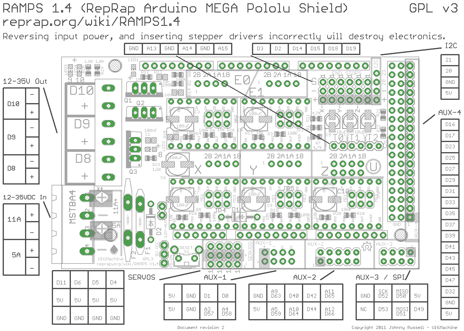
When looking at the Ramps 1.4 board with the power-plugs facing left, the endstop-pins are located in the upper right corner as shown in the image.
From left to right we have X-min, X-max, Y-min, Y-max, Z-min, Z-max
The top most pins are Signal pins, the middle pins are ground and the lower pins are 5v/Vcc.
Connecting Endstops
If we use a simple limit-switch as our endstop, shown on an image here, which only uses 2 wires, we are going to connect them to the Signal and Ground pin. It does not matter in which order they are connected. Signal and Ground are the 2 top-most pins.
The limit-switch has 3 legs where 1 is for signal and the other 2 are labeled NC and NO, which means Normally Closed and Normally Open, respectively.
Choosing NC or NO
I prefer using NC which Means a current is running through it all the time. When depressing the arm on the switch the circuit is broken and it triggers a response. It also means a fault is registered if a wire breaks, a connector comes loose, or something similar.
If you use NO the Circuit is closed, a current runs through it, when the arm is depressed. This means that no alarm is triggered if a wire or connector comes.
Some years ago NO was the norm as it wasn't as sensitve to noise and Thus did not make false positive (triggering the endstop) due to noise from motors.
The Electronics now, even on cheap Ramps 1.4 has imrpoved a lot and the noise should not be an issue any more, so I'll recommend using the NC pin.
3-pin endstops
More advanced endstops which have LEDS or other Electronics Integrated use 3 wires. One for signal, ground and 5v/vcc.
When connecting these kinds of endstops it is vitally important that the wires are correctly connected. The Signal and Ground becomes important, as opposed to the 2-wire switches, as you risk shorting out the Electronics if you connect the signal to gnd and gnd to signal, while also using the 5v/vcc pin.
Testing wires
When you have soldered the two wires to your endstop, you should test for continuity on the wires using a Multimeter. If you do not have one, I'll recommend you go buy one. A cheap one will do.
If you use more advanced endstops like IR sensors or similar, you should test it according to the manufacturers documentation.
Step 2: Endstop Status Using Pronterface and Setup Marlin in Arduino


Now we have successfully connected our endstop and it is time to setup our firmware.
Using Pronterface
Fire up Pronterface and connect to your printer.
You can see in the middle of the program, marked by a blue Square, I have added some custom bottoms for actions I use a lot like getting Endstop status, allowing Cold Extrusion and Vis Temperature on Extruder (Vis = show in Danish).
You do not have to create any button, but it is a nice tool. Just click the +, type in some text and the Gcode you want to use. The code for Get Endstop Status is M119
Commands can also just be written in the input boxt in lower right corner, see image, and exectud by pressing enter or send.
Using M119 command
First make sure no endstops are triggered. Move the Axes if neccessary. It makes it much easier to do this if all endstops has the same status. When all is ready you issue the M119 command.
After issueing the command you will most likely see some endstops with the status of OPEN and some with the status TRIGGERED
The ones with the OPEN status are most likely configured correctly, while the other endstops are either defective, activated by your axes or the firmware needs to be corrected.
Fault finding/verifying
Now that we have our status we check to see that all the endstop with OPEN status are working correctly. You do that by manually activating them one by one while issue in the M119 command. If the status does not change when activated it is most likely due to bad pin-wiring on Ramps, but it can also be the firmware.
If you have any endstops not behaving you turn off the printer, unplug the USB and Check the pin-connection.Correct as nesccesary.
Also check for continuity again, using a multimeter.
Make a list of the endstops which shows the staus as TRIGGERED when not triggered, or just keep pronterface open to see the output.
Configuring Marlin firmware in Arduino IDE
Open the Configuration.h file/sketch/tab and scroll Down to the @section homing - around line 330 or so.
Make sure you do not have 2 // in front of #define ENDSTOPPULLUPS. If you have, then remove them, upload the firmware to your printer and redo the tests we just did in Pronterface.
Note: remmeber you have to discconnect in Pronterface before uploading firmware or you will get an error in Arduino IDE
Now go Down a few line to "// Mechanical endstop with COM to ground and NC..." and change the value from false to true or the other way, see image, for the endstops outputting TRIGGERED when not triggered.
// The pullups are needed if you directly connect a mechanical endswitch between the signal and ground pins.
const bool X_MIN_ENDSTOP_INVERTING = false; // set to true to invert...
const bool Y_MIN_ENDSTOP_INVERTING = true; // set to true to invert...
const bool Z_MIN_ENDSTOP_INVERTING = false; // set to true to invert...
const bool X_MAX_ENDSTOP_INVERTING = true; // set to true to invert...
const bool Y_MAX_ENDSTOP_INVERTING = false; // set to true to invert..
const bool Z_MAX_ENDSTOP_INVERTING = false; // set to true to invert...
//#define DISABLE_MAX_ENDSTOPS
//#define DISABLE_MIN_ENDSTOPS
Upload the firmware and redo the test in Pronterface.
I changed my Z-min to true from false and it now displays correctly in Pronterface - see image.
Step 3: All Done. Ready for Motion Configuration

Congratulate yourself as you have just setup one of the most important features of your printer.
You actually don't need to use endstops, but when you do, you really need to have them configured correctly before you can move on and setup the motion of your printer.
I am going to make an Instructable on setting up the movement direction of the axes, homing direction and configuration of Travel limits after homing.
Update: you can find it here: Motion Configuration on Ramps 1.4 with Marlin firmware @section machine

Participated in the
Tech Contest


