CN100555783C - The splice enclosure that reenterable is gone into - Google Patents
The splice enclosure that reenterable is gone into Download PDFInfo
- Publication number
- CN100555783C CN100555783C CNB2005800065645A CN200580006564A CN100555783C CN 100555783 C CN100555783 C CN 100555783C CN B2005800065645 A CNB2005800065645 A CN B2005800065645A CN 200580006564 A CN200580006564 A CN 200580006564A CN 100555783 C CN100555783 C CN 100555783C
- Authority
- CN
- China
- Prior art keywords
- cover
- gone
- closure member
- reenterable
- spatial accommodation
- Prior art date
- Legal status (The legal status is an assumption and is not a legal conclusion. Google has not performed a legal analysis and makes no representation as to the accuracy of the status listed.)
- Active
Links
Images


Classifications
-
- G—PHYSICS
- G02—OPTICS
- G02B—OPTICAL ELEMENTS, SYSTEMS OR APPARATUS
- G02B6/00—Light guides; Structural details of arrangements comprising light guides and other optical elements, e.g. couplings
- G02B6/44—Mechanical structures for providing tensile strength and external protection for fibres, e.g. optical transmission cables
- G02B6/4439—Auxiliary devices
- G02B6/444—Systems or boxes with surplus lengths
- G02B6/4441—Boxes
- G02B6/4446—Cable boxes, e.g. splicing boxes with two or more multi fibre cables
-
- H—ELECTRICITY
- H02—GENERATION; CONVERSION OR DISTRIBUTION OF ELECTRIC POWER
- H02G—INSTALLATION OF ELECTRIC CABLES OR LINES, OR OF COMBINED OPTICAL AND ELECTRIC CABLES OR LINES
- H02G15/00—Cable fittings
- H02G15/013—Sealing means for cable inlets
-
- H—ELECTRICITY
- H02—GENERATION; CONVERSION OR DISTRIBUTION OF ELECTRIC POWER
- H02G—INSTALLATION OF ELECTRIC CABLES OR LINES, OR OF COMBINED OPTICAL AND ELECTRIC CABLES OR LINES
- H02G15/00—Cable fittings
- H02G15/08—Cable junctions
- H02G15/10—Cable junctions protected by boxes, e.g. by distribution, connection or junction boxes
- H02G15/113—Boxes split longitudinally in main cable direction
Abstract
The closure member that a kind of reenterable that is used for the joint between the cable is gone into, it comprises two covers (1,3) with inwall, inwall is configured to define cavity (7,9), is used for blockade line cable joint when cover (1,3) is engaged with each other in make position.In the cover (1,3) at least one also has inwall (15,17), and these inwalls (15,17) are configured to limit the spatial accommodation of surrounding cavity (7,9) at least in part.In use, these spatial accommodations can accommodate encapsulant (27).At least one inwall of a cover can be inserted in the spatial accommodation of another cover, if so that the encapsulant of wherein having packed into, then when cover (1,3) is engaged with each other in make position, spatial accommodation will be squeezed.Be used for accommodating the spatial accommodation of encapsulant (27) by means of change, the protection of the moisture-resistant gas of varying level can be provided for the cable connector in the cavity.
Description
Technical field
The present invention relates to a kind of closure member that is used for the joint between the cable, this closure member can be beaten again out, reenter, so that allow to touch cable connector when needed, afterwards preferably by resealing.Cable can for example be the communications cable, electric power cable or optical fiber cable.
Cable connector can for example be the joint (i.e. joint between the cable that roughly extends from relative direction) of longitudinal extension or so-called " pigtail shape " or the joint that flushes (i.e. joint between the cable that roughly extends from equidirectional).
Background technology
Cable connector needs protection usually and avoids the influence of its residing environment, and especially needs protection and avoid entering of mechanical shock and moisture.Usually cables against strain also needs protection.Provide the closure member multiple different, that be used for cable connector of different degree of protections all can obtain, they comprise the closure member of being gone into by so-called reenterable, and it can be beaten again out, so that no matter when need, all allow the contact joint.
The splice enclosure that known reenterable is gone into is the form that two parts are beaten again out housing usually, limits the cavity around joint, and encapsulant is housed.Housing provides the protection that makes joint avoid mechanical shock, and with encapsulant join protection cavity, to need entering of level opposing moisture, when housing is beaten again out, allow the contact joint simultaneously.In some cases, cavity is full of encapsulant fully (referring to for example U.S. Patent No. 6,169, the splice enclosure of describing in 250), and in other situation, by molded, encapsulant is pre-formed given shape, so that be used in the cable bushing (referring to for example splice enclosure described in the WO 02/063736) that is arranged in shell end.
Summary of the invention
The splice enclosure that provides a kind of reenterable to go into is provided; the protection that it can provide suitable, opposing mechanical shock and moisture to enter for cable connector; and do not need the cavity around joint to be full of any suitable encapsulant, and do not need that encapsulant is pre-formed relative complex so that be used in shape in the cable bushing.Therefore, the invention still further relates to provides a kind of reenterable to go into splice seal, and the protection that it can provide suitable, opposing mechanical shock and moisture to enter for cable connector is used more a spot of relatively encapsulant simultaneously, and is easy to assembling simultaneously relatively.
The invention provides the closure member that a kind of reenterable that is used for the joint between the cable is gone into, this closure member comprises two covers with inwall, and inwall is configured to define cavity, is used for blockade line cable joint when cover is engaged with each other in make position, wherein,
(i) wherein at least one cover has the inwall that is configured to limit spatial accommodation, and spatial accommodation is suitable for accommodating the encapsulant of surrounding cavity at least in part, and
(ii) at least one inwall of a cover can be inserted in the spatial accommodation of another cover, so that when cover was engaged with each other in make position, extruding was housed within the encapsulant in the spatial accommodation.
Advantageously, one of them cover comprises the tension force releasing parts that is associated with described cable admission passage.Like this, closure member can provide the protection of the influence of opposing cable strain for joint, in addition; by cover; the protection of opposing mechanical shock is provided, and, provides and resisted the protection that moisture enters by the combining of any encapsulant in cover and the spatial accommodation.
Description of drawings
Only as an example, describe with reference to the accompanying drawings according to splice enclosure of the present invention, in the accompanying drawings:
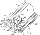
Fig. 1 is the perspective view that is in the exemplary adapter closure member of open mode, has shown the inside of cover;
Fig. 2 is the end-view along the splice enclosure of bold arrow 2 directions of Fig. 1;
Fig. 3 is the zoomed-in view of an end of one of them cover shown in Figure 1;
Fig. 4 is similar to Fig. 1, but has shown another exemplary adapter closure member with the encapsulant that is housed within the spatial accommodation;
Fig. 5 has shown the longitudinal cross-section of the splice enclosure 5-5 along the line shown in Figure 4 that is in closure state;
Fig. 6 has shown the splice enclosure shown in Figure 4 that is in open mode, and is ready to around the cable connector closure;
Fig. 7 is similar to Fig. 1, and has shown the encapsulant that is housed within the spatial accommodation;
Fig. 8 is a splice enclosure shown in Figure 7 sectional view along arrow 8-8 direction;
Fig. 9 is the end-view of magnification ratio of the part of splice enclosure, shows the hinge of revising; With
Figure 10 is the perspective view that is in the another splice enclosure of open mode, has shown the inside of cover.
Embodiment
Fig. 1 has shown the cover 1,3 of two elongations, and they use in the following manner, in order to form the cylindrical protective closure member of vertical line cable joint (not shown).The molded assembly of cover 1,3 for making by appropriate plastic material, for example polypropylene or polyamide, and two covers 1,3 link together by the interior longitudinal edge 2 of hinge 5 along them.Go out hinge 5 and cover 1,3 integrally moulded formation, and it comprises that one subtracts thick district, this has subtracted thick area definition bending axis of hinge as shown.The hinge of this type is known, and is commonly called " living " hinge.
1,3 two of covers all comprise inwall (following more detailed description), and they limit center cavity district 7,9 respectively.When cover 1,3 was folded around hinge 5 and is engaged with each other with the closed joint closure member, cavity zone 7,9 had formed the center enclosed cavity together, is used to hold the cable connector of being protected.For cover 1,3 is remained on make position together, there is grip tab 11 in the outer longitudinal edge 10 of cover unit 1, to raise up, thereby they will slip into the snap close space 10A after the outer longitudinal edge 10 of lower cover member 3, and be engaged in the corresponding opening 12.In addition, in order to reduce the possibility of any relative motion between the cover 1,3, in case they are in detent position, then lower cover member 3 has pin 13, and pin 13 is engaged in the hole 14 of cover unit 1.Like this, when splice enclosure in use, the pressure on the hinge 5 is limited, and makes grip tab 11 drop to minimum from opening 12 out of gear mesh risks unfriendly.
The sidewall 15 of the cavity zone 7 of cover unit 1 and double end walls 17 stand on the outer peripheral horizontal plane top of cover, and be positioned such that, when cover 1,3 folds into when closing with the position together, wall 15,17 will be inserted in the spatial accommodation in surrounding cavity district 9 of lower cover member 3.
The cable admission passage of splice enclosure is also limited by the semi-circular recesses 25B in the end wall 17 of the end wall of cover 1 and cavity zone 7.
Referring now to Fig. 3, Fig. 3 is the zoomed-in view of lower cover member 3 one ends, can see that each strain-relief structures 21 includes three isolated walls 25, and they are parallel to the abutting end 19 of lower cover member 3 and arrange.Wall 25 has held some cable openings 25A, and they depart from each other, thereby limits a cable admission passage that circles round in splice enclosure.Cable admission passage in the splice enclosure is also limited by the semi-circular recesses 25B in the end wall of the end wall of cover 3 and cavity zone 9.What link to each other with groove 25B in the end wall 23 is the surface that can choose employing wantonly, is used to guide cable to enter cavity zone 9, and if necessary, then provides other tension force release action.
Can use the splice enclosure that comprises cover 1,3; and need not to add any encapsulant (promptly; Fig. 1 and the shown form of Fig. 3) so that except the protection that opposing mechanical shock and cable strain are provided, provide the protection of the opposing moisture of basic horizontal for the landing edge between the cable.At first, the ready line cable joint, cable is placed on the lower cover member 3 then, joint itself is positioned in the cavity zone 9, and cable extends to outside the opposite end of cover along the passage that is limited by the groove 25B in the opening 25A in the strain-relief structures 21 and wall 19,17 and 23.Then, around hinge 5, cover unit 1 is folded into downwards on the lower cover member 3, and snap close is in make position.Now, by cover 1,3, protected the opposing moisture of cable connector opposing mechanical shock and basic horizontal, but, still can easily touch cable connector by drawing back cover unit and it being moved to open position.The cable passage that circles round that is limited by opening 25A provides tension force release for cable, and has guaranteed the integrality of joint.
With reference to Fig. 4,, then in the spatial accommodation that the end of cavity zone 7,9 is located, encapsulant 27 is set if cable connector needs the protection of higher levels of opposing moisture.In the situation of cavity zone 9, be maintained in the spatial accommodation at cavity end place the spatial accommodation of side (and can not enter into) in order to guarantee encapsulant 27, the wall 23 of lower cover member 3 stretches out in each end, so that barrier 23A to be provided.Then, at the top cut-in groove 15A of the wall 15 of cover unit 1, so that when splice enclosure is closed, the top that holds barrier 23A.
Then, the ready line cable joint, and place it in above-mentioned and lower cover member as shown in Figure 63 on, Fig. 6 has shown that closure member shown in Figure 4 is using with the situation in the process of protecting two landing edges between the cable 28.Cable is shown as and comprises two couples of lead 28A (but this is not substantial), and they are positioned on the lower cover member 3, make the 28B that is connected between the lead of individual conductor 28A and another root cable of single line cable be positioned at cavity zone 9, and cable 28 is from its opposite end, along being extended out by the groove 25B in opening 25A the strain-relief structures 21 and the wall 19,23.Then, as above-mentioned closed joint closure member, so the top of the barrier 23A in the lower cover member 3 is arranged in the corresponding recesses 15A of cover unit 1.Simultaneously, the upper end wall 17 (with the encapsulant between them 27) at cavity zone 7 ends places will be inserted in the encapsulant 27 at place, end of cavity zone 9, and as shown in Figure 5, Fig. 5 has shown the longitudinal cross-section, center of splice enclosure, for clear, has saved cable.As a result, the encapsulant 27 at the inner chamber two ends of splice enclosure places all is squeezed, and forms sealing with the adjacently situated surfaces of cable and cover effectively.According to the character of encapsulant, it can also trend towards flowing to outside the spatial accommodation, and limits length along the flows outside one of cable, thereby sealing effectiveness is provided.Now, cable connector has been protected to the opposing moisture of better level and as before, opposing mechanical shock and cable strain, but by drawing back cover unit and it is moved to open position, still contact cable taking joint easily.
The encapsulant 27 that is used for closure member shown in Figure 4 can be set as the form of the gel of some moulding in advance, is positioned in the spatial accommodation at end place of cavity zone 7,9.Perhaps, encapsulant can be set as liquid form, and in this case, it is poured in the spatial accommodation, and is solidified into the denseness of similar gels before use in spatial accommodation.By means of the encapsulant that employing has shorter curing time, higher tack, can limit liquid sealing material from the tendency of spatial accommodation by adjacent groove 25A, 25B outflow.
With reference to Fig. 7, if cable connector needs the protection of higher levels of opposing moisture, before the cable that will connect head was placed on the above-mentioned lower cover member 3, the side along cavity zone 9 in spatial accommodation also was provided with other encapsulant 29.In the case, do not need barrier 23A shown in Figure 4 and relevant groove 15A, and can omit.Then, as above-mentioned closed joint closure member, so the sidewall 15 of cavity zone 7 and double end walls 17 (with the encapsulant between them 27) will be inserted in respectively in the encapsulant 29,27 at the side of cavity zone 9 and end place, shown in the sectional view of Fig. 5 and 8.The result; the inner chamber of splice enclosure is surrounded by extruded encapsulant; and the protected one-tenth higher level opposing of cable connector moisture (and as before opposing mechanical shock and cable strain); but, still can easily touch cable connector by drawing back cover unit and it being moved to open position.
As mentioned above, the encapsulant 29,27 that is used for closure member shown in Figure 7 can be set as the form of the gel of some moulding in advance, is positioned in the spatial accommodation at end place of cavity zone 7,9.Perhaps, encapsulant can be set as liquid form, and in this case, it is poured in the spatial accommodation, and is solidified into the denseness of similar gels before use in spatial accommodation.
Comprise that the concrete advantage as the splice enclosure of above-mentioned cover 1,3 is, only by making the suitable position in the cover comprise encapsulant, just can provide the protection of the opposing moisture of several levels with one type closure member.In fact, in each case, although do not need barrier 23A, splice enclosure shown in Figure 4 still can be used to provide the protection of the opposing moisture of three kinds of varying levels, is shown among Fig. 1,4 and 7.To the moisture protection of every kind of level, also provide effective protection of opposing mechanical shock and cable strain for joint.
Splice enclosure has simple structure, and adopts less relatively parts, makes them all assemble easily at the scene even in difficult or not readily accessible place.
Manufacturer or setter can easily need to change the modification of protection level (promptly adding encapsulant), especially when using liquid sealing material, because there is no need to deposit the gel piece that is carried out to given shape.Have only when imperative, just need to use the encapsulant (Fig. 7) of maximum, and this amount still all has been full of the encapsulant that uses in the encapsulant less than the wherein whole joint cavity of the splice enclosure of going at for example reenterable.Thereby, comprise that the cost of the splice enclosure of above-mentioned cover 1,3 can be lower than the cost that whole joint cavity all has been filled the splice enclosure of encapsulant.In addition, cavity zone the 7, the 9th, empty, this allows to make more joint to be accommodated in the single closure member; The better environmental condition that makes the long-term location of joint is provided; And make contact joint simplification when beating again out closure member.
Owing in the splice enclosure shown in Fig. 4 and 7 of accompanying drawing, only used a kind of encapsulant, therefore do not have and the different sealing material between contact-making surface (for example, the joint of encapsulant 27,29 in Fig. 7, the perhaps joint between the encapsulant 27 in upper and lower covers parts 1,3) relevant sealing problem.And, the concrete structure of splice enclosure (as described, when closure member was closed, this structure caused the double end walls 17 of cover unit 1 and the encapsulant 27 that is contained in wherein to be inserted in the encapsulant 27 of lower cover member 3) guaranteed that cable 28 is surrounded fully by the encapsulant 27 in the zone in center cavity 7,9 outsides of adjacent closure member.Thereby eliminated the possibility of the air gap around these local cables, if the encapsulant 27 in the cover unit 1 only is the encapsulant 27 that contacts Face to face in the lower cover member 3, then air gap may appear in these places, if there is air gap, then may allow moisture to enter center cavity 7,9.
In a single day preferably, encapsulant 27,29 has enough long-term elasticity, is squeezed under the effect of closing lid parts 1,3 with assurance, the sealing of then remaining valid is until reopening splice enclosure.Advantageously, encapsulant allows splice enclosure to be resealed (and if necessary, then repeatedly open and reseal) and continues the protection level that provides same for cable connector.U.S. Patent Application Serial Number 10/770 at applicant's while pending trial, a kind of suitable encapsulant has been described in 095, this application is filed on February 2nd, 2004, and name is called " MICROSPHERE-FILLED SEALANT MATERIAL ", and is combined in this as a reference.But, if necessary, then can place one or more outside elastomeric elements the suitable local of cover 1,3 in known manner, so that when splice enclosure is closed, encapsulant is applied required extruding force.
Be appreciated that and make various modifications to the structure of cover 1,3, and can not have influence on the defencive function of splice enclosure.In a modification, the single hinge 5 between two covers 1,3 is replaced by two hinge 5A, 5B, as shown in Figure 9.This modification make splice enclosure can each cover is only moved through with respect to adjacent hinge just can be closed under 90 ° the effect, thereby reduced tension force on each hinge.When adopting single hinge 5, as shown in Figure 2, hinge is not in fact integrally moulded with cover; As an alternative, it can be independent parts, for example is the form of film or band, sandwiches molded or connects with adhesive.Can also revise the shape, position and the quantity that are used to cover is remained in the snap close 11,12 of make position.
Though convenient, the size that the cable that restriction can be used with splice enclosure is set of the strain-relief structures 21 in the splice enclosure.For using, can omit strain-relief structures 21, and replace with traditional cable ties with larger-diameter cable.Perhaps, strain-relief structures 21 can be designed to hold the cable of the maximum gauge that intention uses with splice enclosure, and some other mechanisms can be set, so that closure member can be used with the cable than minor diameter.For example, Figure 10 has shown a kind of splice enclosure, wherein each strain-relief structures 21 all is designed to hold five pairs cable, and cover 3 is expanded at every end, thereby some compartments 30 are provided, cable (for example, two pairs cable) than minor diameter can be fixed on traditional cable ties in these compartments 30.For this purpose, each compartment 30 all has seat 32, aims at the cable openings 25A of adjacent strain-relief structures 21, and provides support for the cable that enters splice enclosure.If cable is too little, can not be suitably fixing with strain-relief structures 21, then can cable be fixed in seat 32 with the cable ties (not shown), cable ties around cable and seat by the hole 34 in the cover 3.
By the advantage that the present invention instructed, those skilled in the art can apply the present invention to the cable of virtually any size or any desired cable logarithm.
In splice enclosure shown in Figure 10, cover 1 is also expanded the length identical with cover 3 at every end place, thereby when cover 1,3 is closed around cable connector, makes compartment 30 sealings of containing seat 32.In modification, cable tray 32 can be arranged to the extension of cover simply, and keeps exposing when splice enclosure is closed.
Figure 10 also shown splice enclosure another revise, be the form (each compartment 30 interior) of two weakening regions 36 in the cover 3, they can pierce through with screw, if necessary, then so that can make closure member can be fixed in flat surface.Substitute as another, the position of screw can be located at the extension of cover 3, makes when splice enclosure is closed, keeps exposing and can touching.
Figure 10 also shown, before using splice enclosure, cable openings/recesses 25A, the 25B in the wall of the spatial accommodation at place, the end of cavity zone 7,9 sealed by rupturable wall portion 26.These wall portions 26 allow liquid sealing material to pour in the spatial accommodation, the horizontal plane until the wall top, and during curing keep.After this, because wall portion 26 can break, so they will be under the effect of the action of the appropriate location in cable being placed into link to each other openings/ recesses 25A, 25B and be removed, thereby makes cable can embed encapsulant effectively.Can in above-mentioned any other splice enclosure, adopt the wall portion of similarly can breaking with reference to accompanying drawing.
Figure 10 has shown that also on the midfeather 25 of each strain-relief structures 21, adjacent hinge 5 places are provided with bossed extendible portion 40.Each extendible portion 40 can both be engaged in the corresponding hole 41 on the hinge opposite side in the cover 1, thereby when cover 1,3 is closed, for hinge provides other protection.
It is also understood that, the joint that can be called as " pigtail shape " with splice enclosure protect the same with the general type shown in the accompanying drawing or flush (i.e. joint between the cable that roughly extends from equidirectional, rather than from as shown in Figure 6 relative direction).In this case, splice enclosure (comprising strain-relief structures 21) will need to revise, so that allow cable to enter closure member from equidirectional usually, rather than as shown in drawings from relative direction.
The further modification of the cable admission passage of above-mentioned any splice enclosure with reference to accompanying drawing all can be for joint between the cable of varying number provides protection, and for example the landing edge between two cables that extend for the single line cable that extends from a direction with from other direction provides protection.
Claims (13)
1. closure member that the reenterable that is used for cable connector is gone into, this closure member comprises:
Have first and second covers (1,3) of inwall (17,23,25), inwall is configured to define cavity (7,9), is used for blockade line cable joint when cover (1,3) is engaged with each other in make position, wherein,
The inwall of two covers (1,3) (17,23,25) is configured to limit spatial accommodation (17A), and this spatial accommodation is suitable for accommodating the encapsulant (27) that centers on described cavity (7,9) at least in part, and
At least one inwall in the cover (1,3) (17,23,25) can be inserted in the spatial accommodation of another cover (1,3), so that when cover (1,3) is engaged with each other in make position, extruding is housed within the encapsulant (27) in the spatial accommodation,
It is characterized in that the spatial accommodation (17A) in the cover (1,3) can be inserted in another cover (1,3) in the spatial accommodation in, thereby when cover (1,3) was engaged with each other in make position, extruding was housed within the encapsulant (27) in two spatial accommodations (17A).
2. the closure member that reenterable as claimed in claim 1 is gone into, wherein, described spatial accommodation is around the cable admission passage that enters described cavity, and wherein said cable admission passage crosses described spatial accommodation.
3. the closure member that reenterable as claimed in claim 1 is gone into, wherein, the sealing material has been poured in the spatial accommodation and has been solidified subsequently.
4. the closure member that reenterable as claimed in claim 1 is gone into, wherein, spatial accommodation all accommodates identical encapsulant.
5. the closure member that reenterable as claimed in claim 1 is gone into, wherein, the cavity that is used for the blockade line cable joint does not have encapsulant.
6. the closure member that reenterable as claimed in claim 2 is gone into, wherein, at least one cover comprises the tension force releasing parts that is associated with described cable admission passage.
7. the closure member that reenterable as claimed in claim 1 is gone into, wherein, cavity has elongate in shape, and the closure member that described reenterable is gone into comprises the some cable admission passages that enter this cavity from the longitudinal relative end of this cavity.
8. the closure member that reenterable as claimed in claim 7 is gone into, wherein, the described spatial accommodation that is gone out by inner wall limit is included in the some horizontal spatial accommodation of the described longitudinal relative end of cavity.
9. the closure member that reenterable as claimed in claim 8 is gone into, wherein, the cable admission passage crosses described horizontal spatial accommodation.
10. the closure member that reenterable as claimed in claim 8 is gone into, wherein, in at least one cover, the described spatial accommodation that is gone out by inner wall limit also comprises some vertical spatial accommodations, and extend these vertical spatial accommodations vertical both sides along this cavity between the longitudinal relative end of cavity.
11. the closure member that reenterable as claimed in claim 1 is gone into, wherein, cover is connected to each other by at least one hinge.
12. the closure member that reenterable as claimed in claim 1 is gone into, wherein, cover releasably is engaged with each other.
13. the closure member that reenterable as claimed in claim 1 is gone into, wherein, cover is a molded assembly.
Applications Claiming Priority (2)
| Application Number | Priority Date | Filing Date | Title |
|---|---|---|---|
| US10/770,377 | 2004-02-02 | ||
| US10/770,377 US7141738B2 (en) | 2004-02-02 | 2004-02-02 | Re-enterable splice enclosure |
Publications (2)
| Publication Number | Publication Date |
|---|---|
| CN1926738A CN1926738A (en) | 2007-03-07 |
| CN100555783C true CN100555783C (en) | 2009-10-28 |
Family
ID=34808317
Family Applications (1)
| Application Number | Title | Priority Date | Filing Date |
|---|---|---|---|
| CNB2005800065645A Active CN100555783C (en) | 2004-02-02 | 2005-01-04 | The splice enclosure that reenterable is gone into |
Country Status (16)
| Country | Link |
|---|---|
| US (1) | US7141738B2 (en) |
| EP (1) | EP1711989B1 (en) |
| JP (1) | JP4749342B2 (en) |
| CN (1) | CN100555783C (en) |
| AT (1) | ATE395739T1 (en) |
| AU (1) | AU2005211099A1 (en) |
| BR (1) | BRPI0507368B1 (en) |
| CA (1) | CA2554960A1 (en) |
| DE (1) | DE602005006741D1 (en) |
| DK (1) | DK1711989T3 (en) |
| EG (1) | EG24471A (en) |
| MY (1) | MY139820A (en) |
| NO (1) | NO20063625L (en) |
| RU (1) | RU2361347C2 (en) |
| TW (1) | TW200537778A (en) |
| WO (1) | WO2005076427A1 (en) |
Families Citing this family (64)
| Publication number | Priority date | Publication date | Assignee | Title |
|---|---|---|---|---|
| US7141738B2 (en) * | 2004-02-02 | 2006-11-28 | 3M Innovative Properties Company | Re-enterable splice enclosure |
| US7273984B2 (en) * | 2005-07-11 | 2007-09-25 | Twins Investments Company | Outdoor cord connection cover apparatus |
| CN101170247B (en) * | 2006-10-27 | 2010-05-19 | 3M新设资产公司 | Re-accessible connector enclosing cover |
| US7618269B2 (en) * | 2007-02-28 | 2009-11-17 | Hubbell Incorporated | Compliant cap |
| US7453042B2 (en) * | 2007-04-09 | 2008-11-18 | Andrew Llc | Cable and apparatus interconnection close quarters environmental seal |
| JP2009020221A (en) * | 2007-07-11 | 2009-01-29 | Fujikura Ltd | Optical closure and method of optical wiring from optical cable assembly to subscriber's house |
| US7562864B2 (en) * | 2007-10-09 | 2009-07-21 | Robbins Iii Edward S | Fence splice cover assembly |
| US7885505B2 (en) | 2007-10-22 | 2011-02-08 | Adc Telecommunications, Inc. | Wavelength division multiplexing module |
| US7536075B2 (en) * | 2007-10-22 | 2009-05-19 | Adc Telecommunications, Inc. | Wavelength division multiplexing module |
| FR2926166B1 (en) * | 2008-01-08 | 2010-06-11 | Ge Energy Products France Snc | KIT OF TEMPERATURE SENSORS, IN PARTICULAR FOR COMBUSTION TURBINE. |
| US7697812B2 (en) * | 2008-01-18 | 2010-04-13 | 3M Innovative Properties Company | Enclosure and organizer for telecommunication lines and splices |
| US8107816B2 (en) | 2008-01-29 | 2012-01-31 | Adc Telecommunications, Inc. | Wavelength division multiplexing module |
| DE102008051482A1 (en) * | 2008-04-01 | 2009-10-08 | Zumtobel Lighting Gmbh | Strain relief device |
| SE532380C2 (en) * | 2008-09-23 | 2009-12-29 | Syntune Ab | Waveguide for low reflex switch-off. |
| ES2380503T3 (en) * | 2008-10-30 | 2012-05-14 | 3M Innovative Properties Company | Waterproof case |
| CN102388516B (en) * | 2008-11-18 | 2014-10-29 | 泰科电子有限公司 | Sealant-filled enclosures and methods for environmentally protecting a connection |
| CA2988835C (en) * | 2008-11-18 | 2020-01-21 | Tyco Electronics Corporation | Sealant-filled enclosures and methods for environmentally protecting a connection |
| TWI420768B (en) * | 2009-02-26 | 2013-12-21 | Chi Yu Fen | Communication cable connection box with flexible rubber shrink tube waterproof device |
| MX2012010844A (en) * | 2010-03-29 | 2012-10-15 | Afl Telecommunications Llc | High fiber count package inner module. |
| CN102221735B (en) * | 2010-04-16 | 2013-07-17 | 泰科电子(上海)有限公司 | Cable connector box |
| DE202010006582U1 (en) * | 2010-05-07 | 2010-08-05 | CCS Technology, Inc., Wilmington | Inline cable sleeve |
| WO2011162926A2 (en) * | 2010-06-21 | 2011-12-29 | 3M Innovative Properties Company | Sealing member for an enclosure |
| CN102331609B (en) * | 2010-07-13 | 2015-05-27 | 泰科电子(上海)有限公司 | Optical fiber terminal box |
| CN201789149U (en) * | 2010-08-10 | 2011-04-06 | 泰科电子(上海)有限公司 | Sealing device for sealing connecting piece |
| CN201829633U (en) * | 2010-08-18 | 2011-05-11 | 泰科电子(上海)有限公司 | Sealed junction box |
| EP2630711B1 (en) | 2010-10-19 | 2014-09-03 | 3M Innovative Properties Company | Enclosure for a cable connection |
| CN103201516B (en) * | 2010-11-10 | 2016-08-03 | 艾默生环境优化技术有限公司 | Compressor and the enclosure assemblies for electric component |
| US8476540B2 (en) | 2010-12-14 | 2013-07-02 | Trystar, Inc. | Shelter for portable electrical inlets/outlets |
| WO2013109305A1 (en) | 2011-08-19 | 2013-07-25 | Aerovironment, Inc. | Water-tight compartment with removable hatch and two-sided gel seal for multiple conduit access |
| US8960973B1 (en) * | 2011-10-06 | 2015-02-24 | Cooper Technologies Company | Splice enclosure for luminaires |
| US9480177B2 (en) | 2012-07-27 | 2016-10-25 | Emerson Climate Technologies, Inc. | Compressor protection module |
| WO2014035611A1 (en) * | 2012-08-30 | 2014-03-06 | 3M Innovative Properties Company | Sealed fiber optic splice tray |
| US9326391B2 (en) | 2012-08-31 | 2016-04-26 | Apple Inc. | Combined audio jack and mobile electronic device enclosure |
| US9594227B2 (en) | 2013-05-09 | 2017-03-14 | CommScope Connectivity Belgium BVBA | Sealing block with stackable sealing elements |
| US11098502B2 (en) | 2014-05-15 | 2021-08-24 | Steven Joseph Jaworski | Tamper proof cable lock |
| WO2015200321A1 (en) | 2014-06-23 | 2015-12-30 | Adc Telecommunications, Inc. | Fiber cable fan-out assembly and method |
| US9363343B2 (en) * | 2014-08-29 | 2016-06-07 | Apple Inc. | Audio jack connector integrated into enclosure |
| ES1132305Y (en) * | 2014-10-22 | 2015-01-28 | Simon S A U | Quick flanging device for electrical connections |
| US10054753B2 (en) | 2014-10-27 | 2018-08-21 | Commscope Technologies Llc | Fiber optic cable with flexible conduit |
| AT517416B1 (en) * | 2015-05-06 | 2017-06-15 | Gebauer & Griller Kabelwerke Ges M B H | CABLE AND METHOD FOR PRODUCING A CABLE |
| AU2015207954C1 (en) | 2015-07-31 | 2022-05-05 | Adc Communications (Australia) Pty Limited | Cable breakout assembly |
| JP6342859B2 (en) * | 2015-08-18 | 2018-06-13 | 矢崎総業株式会社 | Optical connector |
| CN108780200B (en) | 2016-03-18 | 2021-05-07 | 康普技术有限责任公司 | Fiber optic cable fanout duct structures, components and methods |
| EP3507633A4 (en) | 2016-08-31 | 2020-04-01 | Commscope Technologies LLC | Fiber optic cable clamp and clamp assembly |
| WO2018071481A1 (en) | 2016-10-13 | 2018-04-19 | Commscope Technologies Llc | Fiber optic breakout transition assembly incorporating epoxy plug and cable strain relief |
| JP6466983B2 (en) * | 2017-03-22 | 2019-02-06 | 京セラ株式会社 | connector |
| USD960115S1 (en) | 2017-04-20 | 2022-08-09 | University Of Tennessee Research Foundation | Tampering detection enclosure |
| USD960114S1 (en) | 2017-04-20 | 2022-08-09 | University Of Tennessee Research Foundation | Tampering detection enclosure |
| USD826875S1 (en) * | 2017-04-20 | 2018-08-28 | University Of Tennessee Research Foundation | Tampering detection clamping box for ingress and egress lines |
| WO2018208518A1 (en) | 2017-05-08 | 2018-11-15 | Commscope Technologies Llc | Fiber-optic breakout transition assembly |
| USD848992S1 (en) * | 2017-05-26 | 2019-05-21 | Samsung Electronics Co., Ltd. | Connecting device for wireless communications |
| US10283954B2 (en) * | 2017-07-28 | 2019-05-07 | Nicholas T. Tavare | Connection shield for power distribution networks |
| WO2019190760A1 (en) | 2018-03-29 | 2019-10-03 | Corning Research & Development Corporation | Pre-mold assembly for branched optical cable and related method |
| US11561354B2 (en) | 2018-05-09 | 2023-01-24 | Afl Telecommunications Llc | Butt closures and bases therefor |
| IT201800005665A1 (en) * | 2018-05-24 | 2019-11-24 | CONNECTION BOX, IN PARTICULAR FOR THE SEALING AND INSULATION OF ELECTRICAL AND SIMILAR CONNECTIONS | |
| CN109217227A (en) * | 2018-08-15 | 2019-01-15 | 深圳供电局有限公司 | A kind of high-voltage cable middle joint protecting crust that screw rod is reinforced |
| CN108879578A (en) * | 2018-08-16 | 2018-11-23 | 深圳供电局有限公司 | A kind of stackable cable intermediate joint protecting crust |
| EP3939134A4 (en) * | 2019-03-13 | 2023-03-08 | CommScope Technologies LLC | Re-enterable enclosure with environmental sealing |
| JP7272032B2 (en) * | 2019-03-20 | 2023-05-12 | 住友電装株式会社 | connector |
| EP3981052A4 (en) * | 2019-06-05 | 2023-10-11 | Tyco Fire Products LP | Clamping connector |
| US11515696B2 (en) * | 2019-12-17 | 2022-11-29 | Te Connectivity Solutions Gmbh | Electrical component enclosure with injected seal and method |
| US10996414B1 (en) | 2020-03-23 | 2021-05-04 | Afl Telecommunications Llc | Butt closures and bases therefor |
| WO2021203116A1 (en) * | 2020-04-02 | 2021-10-07 | Commscope Technologies Llc | Cable cuffs for multiple sized cables |
| CN113451804A (en) * | 2021-06-30 | 2021-09-28 | 贵州电网有限责任公司 | High-reliability multifunctional interface suitable for 500kV relay protection |
Family Cites Families (42)
| Publication number | Priority date | Publication date | Assignee | Title |
|---|---|---|---|---|
| US3183302A (en) | 1962-01-08 | 1965-05-11 | Jasper Blackburn Corp | Cover for an electrical connector |
| US4449015A (en) | 1981-05-18 | 1984-05-15 | Proto Production Plastics, Inc. | Connector cover with multiple mounting means |
| US4423918A (en) | 1981-08-18 | 1984-01-03 | Minnesota Mining & Manufacturing Company | Re-enterable service wire splice closure |
| US4451696A (en) | 1982-11-15 | 1984-05-29 | Amp Incorporated | Toolless splice sealant device |
| EP0233417B1 (en) | 1986-02-21 | 1990-01-31 | ETABLISSEMENTS MOREL - ATELIERS ELECTROMECANIQUES DE FAVIERES (Société Anonyme) | Sleeve of plastics material for avoiding the splicing of electrical or communication cables, and process for ensuring the sealing capacity of such a sleeve |
| WO1986004181A1 (en) * | 1985-01-04 | 1986-07-17 | Raychem Corporation | Splice case |
| US4610738A (en) | 1985-01-04 | 1986-09-09 | Raychem Corporation | Encapsulating a splice with a gel-filled case |
| JP2510577B2 (en) | 1987-05-13 | 1996-06-26 | 東芝シリコ−ン株式会社 | Curable silicone gel composition |
| US4849580A (en) | 1988-02-11 | 1989-07-18 | Minnesota Mining And Manufacturing Company | Environmental protection closure for wire splices; and method |
| US4879436A (en) | 1988-08-18 | 1989-11-07 | Northern Telecom Limited | Closure for telecommunications cable |
| TR24079A (en) | 1988-11-09 | 1991-03-01 | Raychem Sa Nv | CLOSING LUGGAGE |
| WO1990010035A1 (en) | 1989-03-01 | 1990-09-07 | Raychem Corporation | Method of curing organopolysiloxane compositions and compositions and articles therefrom |
| JPH0353466A (en) | 1989-07-19 | 1991-03-07 | Three Bond Co Ltd | Coating member for joint member |
| GB9112181D0 (en) | 1991-06-06 | 1991-07-24 | Raychem Sa Nv | Cable sealing |
| KR970003184B1 (en) | 1991-06-07 | 1997-03-14 | 레이켐 코포레이션 | Hinged gel-filled security and environmental protection device |
| US5310075A (en) | 1992-11-27 | 1994-05-10 | Distribution Control Systems, Inc. | Waterproof, gasketless enclosure |
| CA2172837A1 (en) | 1993-10-07 | 1995-04-13 | Valere Buekers | Environmental protection |
| GB9322929D0 (en) | 1993-11-08 | 1994-01-05 | Raychem Sa Nv | Cable closure |
| MY112885A (en) | 1993-12-01 | 2001-10-31 | N V Raychem S A | Sealing device. |
| US5397859A (en) | 1993-12-10 | 1995-03-14 | The Whitaker Corporation | Enclosure with sealant for spliced coaxial cables |
| ATE172319T1 (en) | 1993-12-22 | 1998-10-15 | Raychem Ltd | CABLE CONNECTION |
| GB9403838D0 (en) | 1994-02-28 | 1994-04-20 | Raychem Sa Nv | Environmental sealing |
| JPH07245030A (en) * | 1994-03-07 | 1995-09-19 | Sumitomo Wiring Syst Ltd | Grommet |
| US5529508A (en) | 1994-04-01 | 1996-06-25 | Raychem Corporation | Sealing member |
| US5525073A (en) | 1994-06-01 | 1996-06-11 | Raychem Corporation | Environmental protection device with manually operated latch mechanism |
| US5777268A (en) | 1995-10-06 | 1998-07-07 | Raychem Corporation | Splice closure for buried telecommunications cables |
| GB9505458D0 (en) | 1995-03-17 | 1995-05-03 | Raychem Ltd | An article for protecting a multi-conductor connector |
| EP0733672B1 (en) | 1995-03-22 | 1997-09-03 | ERNST SONDERHOFF GmbH & Co. KG | Method of manufacturing a (foamed) soft elastic silicone elastomer, especially for sealing purposes |
| US5763835A (en) | 1995-11-01 | 1998-06-09 | Raychem Corporation | Gel-filled closure |
| ID15837A (en) | 1996-01-24 | 1997-08-14 | Raychem Sa Nv | CABLE COVER |
| US5844171A (en) | 1997-04-22 | 1998-12-01 | Mev Corporation | Environmentally enclosed cable splice |
| JPH1141781A (en) * | 1997-07-22 | 1999-02-12 | Harness Sogo Gijutsu Kenkyusho:Kk | Waterproof case at wire joint |
| FR2770048B1 (en) | 1997-10-16 | 1999-12-31 | Rxs Morel Accessoires De Cable | SPLICE PROTECTION DEVICE AND METHOD FOR ALLOWING THE PLACEMENT OF SUCH A DEVICE |
| JPH11204982A (en) * | 1998-01-08 | 1999-07-30 | Takeuchi Kogyo Kk | Noise absorber |
| GB9815080D0 (en) | 1998-07-10 | 1998-09-09 | Dow Corning Sa | Compressible silicone composition |
| FR2789816B1 (en) | 1999-02-17 | 2001-03-30 | Rxs Morel Accessoires De Cable | SPLICE PROTECTION DEVICE |
| US6169250B1 (en) * | 1999-04-29 | 2001-01-02 | 3M Innovative Properties Company | Low voltage re-enterable splice enclosure |
| JP3430404B2 (en) * | 2000-08-11 | 2003-07-28 | 株式会社ニチフ端子工業 | Connector waterproof cover |
| FR2820555B1 (en) | 2001-02-06 | 2003-04-11 | 3M Innovative Properties Co | WATERPROOF AND MODULAR CABLE PASSAGE WITH EASY CABLE POSITIONING AND SLEEVE EQUIPPED WITH SUCH A PASSAGE |
| JP2002294076A (en) | 2001-04-02 | 2002-10-09 | Dow Corning Toray Silicone Co Ltd | Silicone gel composition for molding in metal mold |
| CN1269260C (en) * | 2002-10-18 | 2006-08-09 | 矢崎总业株式会社 | Sealing-up structure of insulate line |
| US7141738B2 (en) * | 2004-02-02 | 2006-11-28 | 3M Innovative Properties Company | Re-enterable splice enclosure |
-
2004
- 2004-02-02 US US10/770,377 patent/US7141738B2/en not_active Expired - Lifetime
-
2005
- 2005-01-04 DK DK05704941T patent/DK1711989T3/en active
- 2005-01-04 AU AU2005211099A patent/AU2005211099A1/en not_active Abandoned
- 2005-01-04 EP EP05704941A patent/EP1711989B1/en active Active
- 2005-01-04 BR BRPI0507368-5A patent/BRPI0507368B1/en active IP Right Grant
- 2005-01-04 CN CNB2005800065645A patent/CN100555783C/en active Active
- 2005-01-04 WO PCT/US2005/000107 patent/WO2005076427A1/en active Application Filing
- 2005-01-04 DE DE602005006741T patent/DE602005006741D1/en not_active Expired - Fee Related
- 2005-01-04 AT AT05704941T patent/ATE395739T1/en not_active IP Right Cessation
- 2005-01-04 CA CA002554960A patent/CA2554960A1/en not_active Abandoned
- 2005-01-04 RU RU2006128074/09A patent/RU2361347C2/en active
- 2005-01-04 JP JP2006552116A patent/JP4749342B2/en active Active
- 2005-01-18 TW TW094101436A patent/TW200537778A/en unknown
- 2005-01-29 MY MYPI20050368A patent/MY139820A/en unknown
-
2006
- 2006-08-10 NO NO20063625A patent/NO20063625L/en not_active Application Discontinuation
-
2008
- 2008-08-02 EG EGNA2006000731 patent/EG24471A/en active
Also Published As
| Publication number | Publication date |
|---|---|
| JP2007520990A (en) | 2007-07-26 |
| BRPI0507368A (en) | 2007-07-10 |
| RU2361347C2 (en) | 2009-07-10 |
| EG24471A (en) | 2009-08-03 |
| TW200537778A (en) | 2005-11-16 |
| US20050167147A1 (en) | 2005-08-04 |
| RU2006128074A (en) | 2008-03-10 |
| CA2554960A1 (en) | 2005-08-18 |
| NO20063625L (en) | 2006-11-01 |
| EP1711989B1 (en) | 2008-05-14 |
| DE602005006741D1 (en) | 2008-06-26 |
| DK1711989T3 (en) | 2008-09-01 |
| CN1926738A (en) | 2007-03-07 |
| US7141738B2 (en) | 2006-11-28 |
| AU2005211099A1 (en) | 2005-08-18 |
| EP1711989A1 (en) | 2006-10-18 |
| BRPI0507368B1 (en) | 2018-07-24 |
| ATE395739T1 (en) | 2008-05-15 |
| WO2005076427A1 (en) | 2005-08-18 |
| JP4749342B2 (en) | 2011-08-17 |
| MY139820A (en) | 2009-10-30 |
Similar Documents
| Publication | Publication Date | Title |
|---|---|---|
| CN100555783C (en) | The splice enclosure that reenterable is gone into | |
| CN102498627B (en) | Sealant filled type sealing cover and the method for environmental protection is carried out for butt joint | |
| CN101170247B (en) | Re-accessible connector enclosing cover | |
| AU721422B2 (en) | Cable closure | |
| US9632268B2 (en) | Pressure actuated sealant assembly | |
| AU626154B2 (en) | Splice case | |
| JP2622480B2 (en) | Method and apparatus for protective inclusion of electrical cable | |
| US5371323A (en) | Splice housing apparatus | |
| CA2347841C (en) | Cable closure | |
| CN102576994B (en) | Sealant-filled enclosures and methods for environmentally protecting a connection | |
| JP2000516729A (en) | Fiber optic splice closure | |
| CN102331609B (en) | Optical fiber terminal box | |
| JP2578459Y2 (en) | Waterproof protective cover | |
| JP3504846B2 (en) | Waterproof protective cover | |
| KR20070017121A (en) | Re-enterable splice enclosure | |
| EP2557442B1 (en) | Cable closure | |
| MXPA06008744A (en) | Re-enterable splice enclosure | |
| WO1998049755A1 (en) | Connector protective cover | |
| JPH11329528A (en) | Waterproof protecting cover | |
| JPH1074547A (en) | Water-proof protecting cover | |
| AU1320092A (en) | Splice case |
Legal Events
| Date | Code | Title | Description |
|---|---|---|---|
| C06 | Publication | ||
| PB01 | Publication | ||
| C10 | Entry into substantive examination | ||
| SE01 | Entry into force of request for substantive examination | ||
| C14 | Grant of patent or utility model | ||
| GR01 | Patent grant | ||
| TR01 | Transfer of patent right |
Effective date of registration: 20180720 Address after: American New York Patentee after: Corelle Stolle Research and Development Corporation Address before: American Minnesota Patentee before: 3M Innovation Co., Ltd. |
|
| TR01 | Transfer of patent right |