CN1281989A - Distorting/power failure distinguishing method and equipment - Google Patents
Distorting/power failure distinguishing method and equipment Download PDFInfo
- Publication number
- CN1281989A CN1281989A CN 00119960 CN00119960A CN1281989A CN 1281989 A CN1281989 A CN 1281989A CN 00119960 CN00119960 CN 00119960 CN 00119960 A CN00119960 A CN 00119960A CN 1281989 A CN1281989 A CN 1281989A
- Authority
- CN
- China
- Prior art keywords
- shell
- ammeter
- circuit
- processor
- installation site
- Prior art date
- Legal status (The legal status is an assumption and is not a legal conclusion. Google has not performed a legal analysis and makes no representation as to the accuracy of the status listed.)
- Pending
Links
Images


Classifications
-
- G—PHYSICS
- G01—MEASURING; TESTING
- G01R—MEASURING ELECTRIC VARIABLES; MEASURING MAGNETIC VARIABLES
- G01R22/00—Arrangements for measuring time integral of electric power or current, e.g. electricity meters
- G01R22/06—Arrangements for measuring time integral of electric power or current, e.g. electricity meters by electronic methods
- G01R22/061—Details of electronic electricity meters
- G01R22/066—Arrangements for avoiding or indicating fraudulent use
-
- G—PHYSICS
- G01—MEASURING; TESTING
- G01R—MEASURING ELECTRIC VARIABLES; MEASURING MAGNETIC VARIABLES
- G01R22/00—Arrangements for measuring time integral of electric power or current, e.g. electricity meters
Abstract
An electrical utility meter includes a source of energy consumption measurement signals, a removable housing, a measurement circuit, and a tamper protection circuit. The removable housing has an installed position and an uninstalled position. The removable housing further has a power input for receiving electrical power from a power line when in the installed position. The measurement circuit is secured to the housing and is coupled to the source of energy consumption measurement signals to receive energy consumption measurement signals therefrom when the housing is in the installed position. The measurement circuit is configured to generate metering information based at least in part on said measurement signals. The tamper detection circuit is secured to the housing and is operable to detect an interruption of the electrical power to the housing input and determine whether the housing is in the uninstalled position when an interruption of the electrical power to the housing input is detected.
Description
The present invention relates to watt-hour meter, particularly, relate to watt-hour meter comprising electronic measurement circuit.
Watt-hour meter is a kind of being used for, and especially, surveys the device of power consumption.Many ammeters comprise the employed ammeter of relevant residential district user, are made up of the closed cell between the electric system that is connected utility power line and user.Ammeter is based on the amount of passing through and measures and write down power consumption.Usually, public utility supplier draws the information of consumption from each ammeter, thereby charges to the client.
Watt-hour meter adopts the disk of rotation in history always, and it moves by electromagnetic induction.The disk of rotation is proportional to the electric power amount rotation of consumption.The a series of mechanical counter accumulations in ammeter or the rotating cycle of registration disk.Then, power department is charged to the user according to the rotating cycle that has been occurred since the last time charge.
Recently introduced ammeter is an accumulation power consumption information and do not use rotating circular disk.Such ammeter obtains power consumption information by using digital processing technology.Ammeter has not singly been eliminated motion parts and typically relevant with it shortcoming, and is easy to realize the information processing of perfectly consuming energy, and this can be used for improving the NE BY ENERGY TRANSFER networks efficiency.Ammeter typically comprises power consumption measuring-signal source and metering circuit.The power consumption measuring-signal is simulating signal typically, and they have represented system's power consumption of being measured.Metering circuit is signal digitalized energy measurement, then digitized signal is calculated, and draws with watt-hour, voltampere-hour and/or other consumption information about the form of the numerical value of energy.Metering circuit accumulation power consumption information is used for charge and other purposes.
The common issue with relevant with metering is to distort the energy stealing of carrying out by ammeter.Ammeter is distorted and is only just caused annual several hundred million dollars loss at north America region.The main target that ammeter is distorted is to consume the electric energy of not measured or accumulating by ammeter.Avoiding the tangible method of the electric power of stoichiometric consumption is that ammeter is taken off from line of electric force, so that do not produce record for the electric power that consumes when ammeter is removed.Then, before the personnel of tabling look-up returned meter reading, ammeter can be reconnected.
In order to detect such removal, ammeter usually comprises packoff, must stave this device and could implement to remove ammeter.Packoff can comprise that special sealing wax is in conjunction with an iron wire ring.Great majority comprise that the packoff of above-mentioned wax and iron wire sealing is destroyed when ammeter is removed.Therefore, if ammeter was removed and be resumed in the past in the personnel's of tabling look-up meter reading of returning, then the personnel of tabling look-up can detect the incident of distorting by observing damaged sealing.Use such packoff, or the packoff that uses separately, having such shortcoming, promptly each ammeter takes off from line of electric force all to be needed to recover, and no matter whether such removal relates to and distort.Therefore, the ammeter attendant may be distorted or ammeter when needing repairing at ammeter, must carry the material and the instrument that are used to reseal ammeter.
Use the above shortcoming of ammeter packoff in the design of modular ammeter, to be exaggerated separately.Particularly, developed the modular ammeter, wherein high electric power sensing element is in the box that separates with processing/metering circuit.Because the processing/metering circuit of such modular ammeter is used for registering and showing the power consumption information of accumulation, so as long as remove the module that comprises processing/metering circuit, the modular ammeter is stolen with regard to the easier energy that is subjected to like this.Yet in theory, the packoff of the independent use of prior art can be used on processing/measurement module and sensing module interconnected and detect such distorting.
Yet the packoff that uses is disadvantageous especially in the modular ammeter separately, because in some aspects, comprises that the module of processing/metering circuit is designed to removable.Particularly, a purpose implementing the modular ammeter is to allow ammeter to escalate into to comprise different functions and needn't replace whole ammeter.But, only need to replace processing/measurement module.Therefore, the modular ammeter solves the needs of nearest upgrading ability for the such enhancing that is partly excited by the lack of standardization of power industry.As a result, the removed frequent degree of the processing/measurement module of modular ammeter most likely is much higher than the frequent degree that the single-piece ammeter is removed from line of electric force in history.
Therefore, on the processing/measurement module of modular ammeter, use separately the anti-packoff of distorting to be replaced by the higher frequent degree when using compared with common single-piece ammeter.Like this, the inconvenience that causes owing to the packoff that uses separately has been exaggerated in the design of modular ammeter.
Therefore, need a kind of anti-device of reusing of distorting, it is non-destructive when ammeter is removed, and still writes down or the relevant information of distorting incident of login.And, needing a kind of anti-device of reusing of distorting, it is reused easily, and without any need for special instrument.At last, need such device to have high fiduciary level.
The present invention is by adopting anti-needs and other needs of circuit more than satisfying of distorting in ammeter, whether this resists distorts circuit and be fastened in the removable watchcase and be used for detecting watchcase from watchcase when power supply is removed and correctly installed.Particularly, when the power supply that is added to watchcase is interrupted, detect the potential incident of distorting.Whether this circuit is in correct position by the detection watchcase and makes a distinction distorting with normal power interruption when detecting power interruption.Distort if detect, relevant sign can randomly be set.Then, this sign can be sent to the power department personnel, so that the incident of distorting is informed power department.
In one embodiment, the present invention is the ammeter that is used to measure the electric flux that is consumed by load.This ammeter comprises power consumption measuring-signal source, detachable shell, metering circuit and the anti-circuit of distorting.Detachable shell has an installation site and a non-installation site.Detachable shell also has power input end, when being in the installation site, is used to receive the electric energy from line of electric force.Metering circuit is in the enclosure fastened, and is coupled to power consumption measuring-signal source, receives the power consumption measuring-signal from this signal source when being in the installation site with convenient shell.Metering circuit is made at least in part and produces metrical information based on described measuring-signal.Anti-to distort testing circuit in the enclosure fastened, and the interruption that is used for detecting the electric energy of delivering to the shell input end, and determine whether shell is in non-installation site when detecting the interruption of the electric energy of delivering to the shell input end.
Should be pointed out that after distorting sign and being sent to power department, distorting sign can be reset anti-distorting in the circuit.Therefore, anti-destruction and the replacement that circuit does not cause part of distorting of the present invention.
To more easily understand characteristic discussed above of the present invention and advantage and its its feature by reference the following description and accompanying drawing.
Fig. 1 has shown to have according to the anti-block scheme of distorting the exemplary electronic watt-hour meter of circuit of the present invention, and wherein the shell of electronic electric meter is in non-installation site;
Fig. 2 has shown the block scheme of the ammeter of the Fig. 1 when being in the installation site;
Fig. 3 has shown to have according to the anti-exploded view of distorting the example modules formula ammeter of circuit of the present invention;
Fig. 4 has shown the exploded view of mounting structure of the modular ammeter of Fig. 3;
Fig. 5 has shown the cut-open view of the ammeter of Fig. 3, and wherein measurement module is in the installation site with respect to sensor assembly;
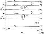
Fig. 6 has shown the principle schematic of sensor assembly of the ammeter of Fig. 3;
Fig. 7 has shown the principle schematic of measuring appliance module of the ammeter of Fig. 3; And
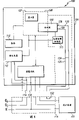
Fig. 8 has shown the exemplary process diagram of operation of processor of the measuring appliance module of Fig. 7.
Figure and 2 block schemes that shown according to exemplary electronic watt-hour meter 100 of the present invention.Ammeter 100 is the devices that are used for measuring the electric energy total amount that is consumed by customer charge 102.Customer charge 102 for example, can be the electric system of industrial plants, commercial department or apartment house.Customer charge 102 is made into the phase A line of electric force φ A from " network " connecting line construction configuration of knowing, and phase C line of electric force φ C and neutral line of electric force N obtain electric power.Yet, should be pointed out that according to ammeter 100 of the present invention easily to be applicable to the electric system that contains by the connecting line construction reception electric energy of any standard that these connecting line constructions include, but not limited to three-way △, four line Y, four line △ and single-phase connecting line construction.
Power consumption measuring-signal source 104 goes for any generation representative and flows through the circuit of signal of electric power of line of electric force φ A, φ C and N or the combination of circuit.For example, power consumption measuring-signal source 104 can suitably comprise one or more voltage sensors and one or more current sensor.Voltage sensor is connected between every phase line of electric force and the neutral line of electric force, and the signal that produces the voltage of representative on each line of electric force.Current sensor can suitably comprise a coil, and it is finished the circuit from phase A line of electric force and φ C line of electric force φ C mutually to customer charge 102 and is used for measuring device at the electric current of coil.In some system, ammeter is not finished the circuit from line of electric force to load, but draws current information from the transformer of the outside that is coupled to line of electric force φ A, φ C.The various forms of voltage sensor (for example bleeder circuit) and current sensor (for example coil of Qian Ruing, power pack and parallel branch) is known.
Metrical information is and the relevant information of being used by the user of energy that typically in standardized unit, it can comprise the kilowatt hour (kwh) of accumulation, volt-ampere-hour (va-hr), or reactive volt-ampere-hour (var-hr) information.Metrical information is typically to be easy to by transmitting or be sent to by visible display a kind of form of power department.The example that can be used for producing from the power consumption measuring-signal the suitable metering circuit of metrical information is discussed in conjunction with Fig. 7 below.
Back with reference to Fig. 1 and 2, anti-distort circuit 110 and also be fastened in the detachable shell 106, it also can be used to detect the interruption of the electric energy that is added to power input end 114,116, and determine whether shell 106 is in non-installation site when detecting such power interruptions.In order to detect the interruption of the electric energy that is added to power input end 114,116, exemplary embodiment as described herein anti-distorted the voltage that circuit 110 can be used to detect output terminal 122 places of power supply 112 and when is reduced to below the predetermined threshold value.
For this reason, in the described here exemplary embodiment, anti-distort circuit 111 and comprise power failure detection circuit 111, it is coupled to the output terminal of power supply 112.Power failure detection circuit 111 shown in Figure 1 is to be used for voltage when output terminal 122 places of power supply 112 to be reduced to the device that predetermined threshold value produces power failure signal when following.For this reason, power failure detection circuit 111 can comprise comparer, has a differential input end that is connected to the Zener diode reference voltage circuit and another differential input end that is connected to power supply output terminal 122.Such circuit is known.
In any case processor 120 of the present invention determines that by using installation continuity circuit detachable shell 106 is in the installation site or is in non-installation site.The continuity circuit is installed is comprised the first shell terminal 124 and the second shell terminal 126.The first shell terminal 124 is coupled to bias voltage source, is shown as first output terminal 128 of processor 120 here.Alternatively, the first shell terminal 124 can be coupled to another bias voltage source, for example the output terminal 122 of power supply 112.The second shell terminal 126 is coupled to the first input end of processor 120.
The first shell terminal 124 is made into that (see figure 2) is electrically coupled to the second shell terminal 126 when detachable shell 106 is in the installation site.On the contrary, the first shell terminal 124 is made into (see figure 1) and the 126 disconnection electric coupling of the second shell terminal when detachable shell 106 is in non-installation site.For this reason, when detachable shell 106 was in the installation site, the part of at least the first shell terminal 124 and the second shell terminal 126 were adjusted to and are electrically coupled to a conductor 132 that is positioned at erecting device 118.
Should be pointed out that processor 120 is suitably programmed, determine that detachable shell 106 is in non-installation site so that whether be added on the second shell terminal 126 according to bias voltage.
In an alternative embodiment, power failure detection circuit 111 are not coupled to the output terminal 122 of power supply 112, but are coupled to power input end 114 and 116.The example of such power failure detection circuit can suitably comprise threshold compataror, is coupled to power input end 114,116, and it produces one and has the pulse width modulating signal of representing the dutycycle of voltage on the line of electric force.Then, whether processor 120 is lower than predetermined threshold value by the dutycycle of determining pulse width modulating signal and determines whether the electric power of delivering to power input end 114,116 interrupts.
And in the embodiment of another replacement, installation continuity circuit need not rely on the conductor 132 in erecting device 118.But, can adopt mechanical switch, when the detachable shell 106 of shell is in the installation site, force this switch to enter primary importance, and when the detachable shell 106 of shell is in non-installation site, this switch is forwarded to the second place.Switch can be made into the circuit that closes between the first shell terminal 124 and the second shell terminal 126 when being in the first position, and opens the circuit between the first shell terminal 124 and the second shell terminal 126 when being in the second place.Though use such switch to eliminate needs, in no case wish moving component is incorporated into anti-distorting in the device of the present invention for erecting device with conductor 132.In another embodiment, the continuity circuit is installed can be comprised optical element, and need not or except electric device.
In the operation of above-mentioned embodiments of the invention, the technician installs detachable shell 106, so that realize the metering of customer charge 102.For this reason, detachable shell 106 is coupled to erecting device 118 (see figure 2)s.When dismountable shell 106 was mounted, power consumption signal source 104 was coupled on line of electric force φ A, φ C, the N.Similarly, the first shell terminal 124 and the second shell terminal 126 carry out electric coupling by conductor 132.
In case be mounted, ammeter 100 is carried out the energy-dissipation measuring functions, knows as technical.Particularly, the voltage and current that power consumption measuring-signal source 104 is detected on line of electric force, and from this signal source generation power consumption measuring-signal.Such signal for example can comprise the simulating signal of representing every voltage waveform of going up mutually and the signal of representing every current waveform of going up mutually.Yet, signal power consumption, that pulse-width signal is provided that other ammeter can adopt representative to be represented by the voltage and current on the line of electric force.The circuit that can produce such power consumption measuring-signal is known.
Simultaneously, power supply 112 receives the AC electric energy from power input end 114 and 116, and provides bias voltage at its output terminal 122.Bias voltage provides biasing electric power to processor 120 and metering circuit 108 and anti-other element of distorting circuit 110 by required strategic point.
Get back to power consumption and measure operation, power consumption measuring-signal source 104 provides the power consumption measuring-signal to metering circuit 108.Metering circuit 108 converts the power consumption measuring-signal to the measuring-signal of numeral.Yet in the embodiment that replaces, power consumption measuring-signal itself may be a digital signal.In any one event, processor 120 or combine individually or with other processor or circuit in the metering circuit 108 produces metrical information from the digital measurement signal.Metrical information particularly comprises the information relevant with power consumption, is called as the power consumption information of accumulation here.The power consumption information of accumulation particularly is used to use for energy and charges to the user.
Then, metrical information is stored and/or outwards transmits.Metrical information can be stored in the storer that is arranged in processor 120, or is arranged in the storer (not shown) of another part of metering circuit 108.Metrical information can provide visible display 121 or the telecommunication circuit (not shown) by the outside outwards to transmit.Employed appropriate display and telecommunication circuit are known technically when conveying and metering information.
The anti-circuit 110 of distorting in the embodiment that is disclosed is normally measuring the operation that in fact run duration does not influence ammeter 100.In any case it is free that processor 120 preferably has an institute of biasing electric power at processor 120, produces the bias voltage with high logic-level voltages form on its first output terminal 128.
In any case, anti-distort circuit 110 mainly detect the electric power that is added to power input end 114 and 116 in the operation of having no progeny., or just be interrupted during from erecting device 118 removals when detachable shell 106 typically only at line of electric force φ A, φ C, when N is subjected to power breakdown at the electric energy at power input end 114 and 116 places.
As what discuss in more detail below, the anti-circuit 110 of distorting of the present invention is distinguished between power breakdown on line of electric force φ A, φ C, the N (not being the incident of distorting) and the removal (constituting the incident of distorting potentially) at detachable shell 106 on the erecting device 118.Particularly, if detachable shell 106 is removed from erecting device 118, as shown in Figure 1, then metering circuit 104 can not produce the metrical information with the power consumption message form of accumulation.If detachable shell 106 is removed and another device is used for finishing circuit between line of electric force φ A, φ C, N and customer charge 102, then customer charge 102 can consume electric power, and not detected, thereby can not charge for electricity usage by power department.In order to detect such energy stealing, the anti-circuit 110 of distorting determines according to the detection for the power interruption that arrives power input end 114,116 whether shell 106 is in the installation site.
By for during the electricity usage and, such operation has been described in anti-discussion of distorting the operation of circuit 110 during the detachable shell 106 of erecting device 118 removals.
During electricity usage, seldom or do not have voltage or electric current on line of electric force φ A, φ C, N, to present electric energy.As a result, seldom or do not have voltage to be provided for power input end 114,116 from phase C line of electric force φ C.Because seldom or do not have voltage to be provided for power input end 114,116, so power supply 112 produces bias voltage on its output terminal 122.Though power supply 112 is because the dissipation of the electric charge on the electric capacity of one or more inside, can in the short time interval, provide bias voltage, but in fact the loss of input electric power causes very big the reducing of the voltage on the output terminal of power supply 112, if not the words of total loss.
When the bias voltage at output terminal 122 places is reduced to predetermined threshold value when following, power failure detection circuit 111 produces power failure signals, and it is offered processor 120.Simultaneously, backup power supply 113, according to reducing of output terminal 122 upper offset voltages, the biasing electric power that begins to provide auxiliary is at least a portion of distorting testing circuit 110 and metering circuit 108., particularly, backup power supply 113 provides assisted bias electric power at least to processor 120.
On the contrary, if detachable shell 106 is removed from erecting device 118, then processor 120 is determined the incident of distorting.
Particularly, when detachable shell 106 when erecting device 118 is removed, power input end 114 disconnects from phase place C line of electric force φ C and connecting, and power input end 116 disconnects from neutral line of electric force N and connecting.Because power input end 114 and 116 disconnects with N from line of electric force φ C respectively be connected, do not have voltage or electric current to power supply 112.As a result, power supply 112 can not produce bias voltage on its output terminal 122.
According to the landing at the voltage at output terminal 122 places, power failure detection circuit 111 is used for producing power failure signal as described above and provides power failure signal to processor 120.Simultaneously, backup power supply 113 also as described above, begins to provide the assisted bias power supply at least to processor 120.Processor 120 receives power failure signal, determines that then high logic-level voltages appears on the first input end 130.
Because power interruption is because detachable shell 106 is removed, the first shell terminal 124 and the second shell terminal 126 no longer are electrically connected by conductor 132.As a result, first input end 130 is not connected to first output terminal 128.Therefore, processor 120 is determined to represent thus that in the high logic-level voltages of first output terminal, 128 generations detachable shell 106 is in non-installation site.
Alternatively, the incident of distorting can be sent to the far-end monitor unit by telecommunication circuit.In case ammeter is taken back in the shell 106, communication just can be implemented like this.
Like this, the testing circuit 110 distorted of the present invention is differentiated and is distorted incident and by sealing wax, sealing and other ruined and must be replaced entity.Particularly, by during detecting the power interruption of delivering to power input end 114 and 116, determine whether shell 106 is in non-installation site, the anti-circuit 110 of distorting is differentiated such situation, forbid that metering circuit 108 work implement the energy stealing thereby wherein attempt removing shell 106, and this situation and the situation that the power supply power failure wherein takes place are made a distinction.Opposite with the design of prior art, the present invention does not need disposable element, and as sealing wax, they need special alternate material.But the present invention only needs common ammeter reading device (such as, reed switch arrangement, press shift knob or programming device), so that in case obtain distorting event information by power department, is used for reconfiguring ammeter.
And above-mentioned embodiments of the invention have design relatively more reliably, because it seldom or not comprises moving parts.Even adopted mechanical switch in the continuity circuit, this switch can have relatively more solid design, because switch value need make according to detachable shell 106 whether be in that the installation site is opened or closed.
The embodiment that has shown a kind of replacement of the present invention on Fig. 3 to 8.The embodiment of this replacement has adopted in modular ammeter 10 according to the anti-circuit of distorting of the present invention.Usually, the modular ammeter is a kind of device, and the measuring-signal source of wherein consuming energy is not to be positioned at the shell that comprises metering circuit.But the metering circuit 42 of modular ammeter is positioned at the first shell 14a, or comprises the part of modular ammeter, is called as measurement module 14.Yet power consumption measuring-signal source, voltage and current sensor 15 are positioned at the second shell 12a, and it holds or support the part of ammeter, is called as sensor assembly.
Anti-to distort circuit be useful especially in the modular ammeter according to of the present invention, because measurement module 14 is estimated to be to remove easily and replace.In other words, though the shell 106 of the modular ammeter 100 on Fig. 1 and 2 seldom be removed, except the incident of distorting.The measurement module 14 of the ammeter 10 of Fig. 3 is designed to be removed, so that realize the upgrading of service and/or metering ability.Therefore, use destructive, independent use, the anti-device of distorting, such as sealing wax, during during interconnected between the measurement module 14 of module ammeter 10 and sensor assembly 12 even compared with interconnected between the shell 106 of the ammeter 100 of figure and 2 and ammeter erecting device 118, not too want.
Referring now to modular ammeter 100, Fig. 3 has shown the cut-open view according to example modules formula ammeter 10 of the present invention.The modular ammeter comprises as the sensor assembly 12 of its basic element of character and measurement module 14.Watt-hour meter 10 is made into as described below, makes measurement module 14 to remove from sensor assembly 12.Exemplary electrical kilsyth basalt 10 is a kind of ammeters that are called as 12S ammeter form in watt-hour meter industry.The ammeter form relates to ammeter and installs, and for example, it is single-phase or polyphase meter.In any case, should be pointed out that the present invention is not limited to relate to the patented claim of 12S ammeter form, and can easily be referred to 2S, 3S, 4S, 8S/9S and other known ammeter form by those skilled in the art.
The shell 12a of sensor assembly 12 holds voltage and current sensor 15, it is according to exemplary embodiment as described herein, comprise first and second power pack 16a and the 16b, first and second current coil 18a and the 18b, and one or more neutral contact chip 20.The first current coil 18a comprises first and second ends, limits the first and second electric current contact chip 22a and 24a respectively and is admitted (see figure 4) by the jaw of compatible ammeter socket.The second current coil 18b similarly comprises first and second ends, limits the first and second electric current contact chip 22b and 24b respectively and is admitted (see figure 4) by the jaw of compatible ammeter socket.
The first and second power pack 16a and 16b are respectively the solenoid shape transformer preferably, have the circle that is limited by circular magnetic core.In the present embodiment, the first power pack 16a has the number of turns ratio of N1 and the number of turns ratio that the second power pack 16b has N2.By using such solenoid current transducer, when assembling, the first current coil 18a passes the solenoidal inside of the first power pack 16a.Preferably, power pack 16a is arranged to make that the axial dimension of power pack 16a is arranged essentially parallel to the axial dimension of shell 12a.In other words, power pack 16a flatly is placed in the sensor assembly shell 12a.The second power pack 16b and the second current coil 18b preferably are placed in the shell 12b in the same way.Therefore, the second power pack 16b flatly is placed in the shell 12b.The use of the solenoid current transducer of horizontal positioned has reduced thickness, has therefore reduced total bulkiness of ammeter 10.
Sensor assembly 12 also comprises electric safe interface 26.Electricity safe interface 26 comprises first interconnect device, is used to be connected to measurement module 14.Electricity safe interface 26 also comprises a device, is used to stop the operator and contacts with the physics of the electric signal of danger potentially that occurs at least a portion of current sensor 15 first.The signal level that is considered to potential danger is known.The signal level that also has different potential dangers.For example, the signal that can produce the shock current that surpasses 70 milliamperes may be a heat injury, and can the constitute a threat to injury of life of the signal that is created in the shock current of 300 milliamperes of magnitudes.And the signal that produces low to 0.5 to 5 milliampere shock current is considered to cause unconscious muscle response.
In the watt-hour meter of the modular ammeter that comprises Fig. 3, some sensor device carries some harmful potentially electric signal at least.Particularly, any part from the voltage and current signal of line of electric force of being electrically connected to of sensor assembly 12 constitutes life and threatens injury, must pass through electric safe interface 26 and contact isolation with human body.In the present embodiment, current coil 18a and 18b are directly connected to the facility line of electric force, so must be isolated.On the contrary, power pack 16a and 16b not necessarily carry life-threatening electric current, because as will be discussed, power pack 16a and 16b are not directly coupled to the facility line of electric force.Therefore, according to the maximum level of the electric current that flows through power pack 16a and 16b of expecting, power pack 16a and 16b may maybe may not carry harmful potentially electric signal.Yet, in any case electric safe interface 26 preferably prevents all parts of human body touch voltage and current sensor, as measuring of safety.
In the present embodiment, be used to prevent that the device of physics contact from comprising top board 28, and a plurality of socket 30a, 30b, 30c, 30d, 30e, 30f and 30g.Each socket 30a has stipulated a perforate on top board 28 to 30g.Except by socket 30a to the perforate of 30g regulation, top board 28 preferably is formed on the space of shell 12a outside and complete dividing plate or the wall between the voltage and current sensor 15.
Alternatively, be at least top board 28 be used for preventing human body touch voltage and current sensor 15 those directly touch the part of the line of electric force of facility, current coil 18a and 18b specifically.
For complete dividing plate is provided, top board 28 combines with the remainder of shell 12a and/or ammeter erecting device or another polycrystalline substance surrounds voltage and current sensor 15 with the bottom from the side.Fig. 4 discusses as following, has described exemplary ammeter erecting device, and it can be used for combining with top board 28, to surround voltage and current sensor 15.
In the embodiment of another replacement, top board 28 can combine with broader shell, and it comprises bigger sidewall and/or polycrystalline substance, is used for surrounding fully voltage and current sensor 15.
Referring again to Fig. 3, socket 30a preferably is made into to the corresponding perforate of 30g and they and prevents the physically current-carrying part of contact base of operator's human body.Particularly, the perforate of being stipulated to 30g by socket 30a has fully small size, prevents the current-carrying part of the test finger piece contact base 30a of standard to 30g.The test finger piece of standard is the mechanical hook-up that uses in electrical industry, is used for determining the whether safety contact that can not caused the accident by human finger of electric-connected socket.A kind of test finger piece of standard is at Underwriter ' s Laboratory, describe among Inc Standard For Safety of Information Technology EquipmentIncluding Electrical Equipment Business (for the standard of the security of the Information Technology Equipment that the comprises electric equipment) UL-1950 (February 26,1993).
In the present embodiment, preferably has first size by socket 30a to the perforate that 30g stipulates, length for example, with second size, width for example, wherein first size has at least and the second measure-alike size, and second size stops very big enter of operator's human body by perforate thus less than 1/8 inch.
In top board 28, also stipulated strip conductor 202.Strip conductor 202 satisfies the effect identical functions that the conductor 132 with the ammeter 100 of Fig. 1 and 2 plays.As what below will discuss, strip conductor 202 provides when measurement module 14 is coupled to sensor assembly 12 and is resisting electrically contacting between the terminal 204 and 206 of distorting circuit.Strip conductor 202 does not preferably carry any harmful potentially voltage, because strip conductor 202 preferably is not connected to any part in the sensor assembly 12, it is coupled to line of electric force again.Therefore, strip conductor 202 not necessarily must be placed on electric safety socket, such as socket 30a, and 30b, or the like.
Here the shell 14a of the measurement module 14 in the exemplary embodiment of Miao Shuing comprises lid 32, printed circuit board (PCB) 34 and pad 36.Being installed to or being fixed on the printed circuit board (PCB) 34 is display 38, metering circuit (not shown) and the anti-circuit (not shown) of distorting.Fig. 7 discusses as following, shows the metering circuit 42 and the anti-circuit block diagram of distorting the exemplary embodiment of circuit 230 that can easily be used in the measurement module 14 of Fig. 1 in greater detail.Yet usually, metering circuit is used for receiving measuring-signal, and produces metrical information from this measuring-signal.Metering circuit is connected provides at least some metrical information to display 38.The anti-circuit of distorting is a kind ofly to be used for determining whether be installed in circuit on the sensor assembly shell 12a detecting measurement module shell 14a after the power breakdown of delivering to measurement module.
Shown an anti-part of distorting circuit on Fig. 3, the first and second shell terminals 204 and 206.The first and second shell terminals 204 and 206 advantageously are placed on the printed circuit board (PCB) 34, and from expansion here, touch conductor 202 when being installed in the sensor assembly with convenient measurement module 14.
Measurement module 14 also comprises second interconnect device, is used for combining with first interconnect device (on sensor assembly), so that the metering circuit of printed circuit board (PCB) 34 is connected to voltage and current sensor 15.For example, in the present embodiment, measurement module 14 comprises a plurality of plug 40a to 40g, and they are admitted to 30g by corresponding a plurality of socket 30a.A plurality of plug 40a when assembled, are electrically connected to metering circuit and the interior printed circuit board (PCB) 34 that physically is connected to 40g.
Fig. 4 has shown mounting structure, and it comprises watt-hour meter 10 and watchcase 13, and watchcase comprises again installs shell 16 and lid 18.Shell 16 is installed structurally as box, is had a perforate and be used to admit lid 18 and cable perforate to be used to admit the line of electric force of the electric system that is measured, not shown.It will be appreciated that shell 16 is installed not to be needed structurally as box, and any other suitable shape can be used also, as long as watchcase lid and a cable perforate of having a perforate to be used to admit to match.Shell 16 is installed is also comprised inner region 20.A plurality of jaws 22 of being made by conductive material are positioned at inner region 20.In the time of in being installed to facility, a plurality of jaws 22 are electrically connected to the line of electric force of the electric system of facility.
A plurality of jaws 22 are admitted and are provided and are electrically connected to current coil contact chip 22a, 24a, 22b and 24b (see figure 1) and neutral contact chip 20.Jaw and contact chip 22a, 24a, the relation of 22b and 24b has also been stipulated the aligning of the sensor assembly 12 in shell 16 is installed.In case contact chip 22a, 24a, 22b and 24b (see figure 3) and 22 engagements (Fig. 4) of a plurality of jaw, sensor assembly 12 just is installed in the inner region 20 that shell 16 is installed.Then, lid 18 is installed to and is installed on the shell 16.Lid 18 comprises ammeter perforate 25, has the circumference by the circumference regulation of sensor assembly 12.Preferably, the circumference of ammeter perforate 25 has shape much at one, and it is slightly less than the circumference of sensor assembly 12, so that sensor assembly 12 can not be removed when lid meshes with installation shell 16.
In case lid 18 is mounted, the measurement module 14 in the present embodiment is placed with and sensor assembly 12 engagements by 18 ammeter perforates 25 of watchcase lid.When engagement, the plug 40a of measurement module 14 is electrically connected to the socket 30a of sensor assembly 12 respectively to 30g to 40g.In case measurement module 14, lid 18, sensor assembly 12 and installation shell 16 all are mounted as described above, ammeter 10 (that is, sensor assembly 12 and measurement module 14) is just finished the energy-dissipation measuring operation for the electric system of facility.
Should be pointed out that if measurement module 14 is removed from sensor assembly then the facility that is connected to of ammeter 10 will continue to accept the electric energy service, but will not be that such electricity usage is paid.It is because pay imformation normally draws in the power consumption information of the accumulation from measurement module 14 that this facility is not paid for such electricity usage, and when measurement module 14 when sensor assembly 12 is removed, measurement module 14 can not get the power consumption information of accumulating.Therefore, potential metering tampering methods is in one day several hours, or removes measurement module 14 from sensor assembly 12 in one day or several days, then, reinstalls measurement module before the power department personnel come meter reading.
As following further discussion, of the present invention anti-distort device be used for reading and/or transmit one about measurement module 14 from sensor assembly 12 removed indications, it can indicate one to distort incident.The power department personnel can easily use conventional equipment (such as by switch) to take out and distort record and/or indication, as following further discussion.Therefore, after the power department technician removed measurement module 14 owing to legal reason, distorting indication can easily be removed.
Fig. 5 has shown the side sectional view of ammeter 10, and wherein measurement module 14 is assembled or be installed on the sensor assembly 12.The panel lid 32 of measurement module comprises the shirt rim 64 of column part 62 and ring-type.Top board 28 parts of sensor assembly 12 are by annular projection 66 regulations.Annular projection 66 is held by the space of defined between the shirt rim 64 of the ring-type of ammeter lid 32 and column part 66.Top board 28 is stipulated by support 68 that also this support is smooth and the close column part 62 of part basically.Support 68 constitutes half of about top board 28.Second half of top board 28 comprises by the following groove 56 of the part regulation at the edge 66 of domatic 70, base plate 72 and ring-type.Domatic 70 stipulated the variation on the degree of depth between support 68 and base plate 72 down.
As discussed above, top board 28 also comprises distorts perforate, on Fig. 5 by the perforate 52d explanation of example.Perforate 52d also exists corresponding to other socket 30a corresponding to socket 30d, 30b, 30c, 30e, the same perforate (see figure 1) of 30f and 30g.It is conical that perforate 52d preferably is slightly, to allow the carrying out aligning adjustment of plug 40d when assembling measurement module 14 is to sensor assembly 12.Socket 30d, it can suitably be a terminal of loading onto spring, is electrically connected to current coil 18b, so that be provided to the connection of the voltage measurement of phase C, discusses in conjunction with Fig. 3 as top.
Fig. 5 further shows the plug 40d that is connected to circuit board 34, and it is inserted into socket 30d by perforate 52d.Socket 30d physically meshes in this wise with plug 40d, so that be provided at the electrical connection between them.Plug 40d compatibly can be common conducting strip.
The first and second shell terminals 204 and 206 on the printed circuit board (PCB) 34 of measurement module 14 extend downwardly into the strip conductor 206 of sensor assembly 12.Therefore, when measurement module 14 socket installation sites, the first and second shell terminals 204 and 206 pass through strip conductor 206 by electric coupling.As what below will further discuss, whether the anti-circuit of distorting is according to there being circuit continuity to determine whether measurement module is in the installation site between the first and second shell terminals 204 and 206.
Can see by reference Fig. 3,4 and 5, electricity safe interface or top board 28, when the meter case that is suitable for matching, be provided at measurement module 14 owing to maintenance or replace the very hard dividing plate between operator or technician's human body and electric current and voltage sensing device when being removed.It will be appreciated that other interconnect device can be used in sensor assembly 12 and the measurement module 14, it also will provide electric safe interface.For example, wireless device can be used as interconnect device.Such wireless device can provide voltage and current measuring-signal from sensor assembly 12 to measurement module 14.For example, measurement module 14 can comprise responsive electric field and magnetic field sensor, and it draws the voltage and current metrical information from the electromagnetic radiation of current coil 18a and 18b.Similarly, optical communication apparatus can be used for providing measuring-signal information to measurement module from sensor assembly 12.Under any circumstance, electric safe interface typically comprises dividing plate, and such as top board 28, it stops operator's human body physics to insert other dangerous part of current coil 18a and 18b and sensor assembly 12 when measurement module 14 is removed.
In order fully to obtain modular benefit, in the design of ammeter 10, must solve the correction problem.Particularly, the transducing part of ammeter must have correcting feature, and this allows it to use together in conjunction with any suitable measure portion.In the ammeter of non-module, metering circuit is usually proofreaied and correct for using specially with specific voltage and current sensor.Special reason of proofreading and correct is to have very big difference in the signal response of each voltage and current sensor.Particularly, current sensor device, power pack for example, the variable signal response that usually has wide range.The signal response of common operational power pack is all wide range ground variations on amplitude and phase response.
The signal response change of such power pack is much bigger compared with the energy measurement accuracy requirement of ammeter.In other words, though the power pack signal response may change 10%, require total ratio of precision 10% of ammeter much smaller.Therefore, for the change of current sensor device, or tolerance, must compensate, to guarantee that the final energy measurement precision of ammeter is in acceptable range of tolerable variance.In the prior art, compensate for typical ground is by adjusting during fabrication or the correcting measuring circuit is realized, so that consider in specific ammeter unit the signal response characteristic of the particular current sensing device that will be used.In other words, each metering circuit is proofreaied and correct for each ammeter customizedly.
Yet real modular ammeter does not need the specific correction in huge like this unit.But the modular element must easily exchange.Therefore, referring again to Fig. 3, sensor assembly 12 is proofreaied and correct in advance is used for modularization, so that sensor assembly 12 can not need the specific correction in unit of this measurement module 14 with any measurement module 14 couplings.
For this reason, sensor assembly 12, voltage and current sensor 15 is proofreaied and correct in advance specifically, so that the signal response that the voltage and current sensor has is in the range of tolerable variance of the signal response of predesignating, this tolerance is not more than the tolerance of the energy measurement precision of ammeter 10.The energy measurement precision of ammeter 10 is defined as the precision for the power consumption of the measurement of the actual energy consumption of facility.Therefore, be 0.5% if require the tolerance of the energy measurement precision of ammeter, then the difference between the power consumption of power consumption of measuring and reality will be no more than 0.5%.Under these circumstances, the signal response of voltage and current sensor will be not more than, and typically widely less than 0.5%.As a result, measurement module 14 can easily replace with another measurement module, and does not need the measurement module of replacing is carried out special correction.
The correction in advance of voltage and current sensor 15 can reach by meticulous manufacture process.Main error source on the signal response of voltage and current sensor 15 is the signal response of power pack 16a and 16b.Usually, operational power pack has change easily in amplitude and phase angle signal response.Therefore, proofread and correct in advance to relate to and use manufactured power pack in needed range of tolerable variance, to carry out.For this reason, power pack 16a and 16b are to use the high permeability core material to make, and it reduces the phase angle error in the signal response.And power pack 16a and 16b are manufactured into and make the actual number of turns be accurately controlled.Produce enough consistance of range signal response for the accurate production control of the number of turns among power pack 16a and the 16b, to allow exchange.
Alternatively, if do not wish to control the number of turns during initial the manufacturing for the reason of cost, then the number of turns can be increased after manufacturing or deduct, to reach the signal response of wanting.For example, buying on the market of very wide tolerance has the power pack of sale and adjusts the number of turns, and compared with the power pack of the enough narrow tolerance of special manufacturing, possible cost is more economical.
Fig. 3,4 and 5 has described a kind of modular ammeter 10 of carrying out function of measuring, and it allows to replace and upgrading measurement module 14, and need not replace whole ammeter.By adopting of the present invention resisting to distort circuit, as discussed below, can finish the replacement of measurement module 14, and not destroy the packoff of distorting of machinery, thereby the packoff of new machinery need not be installed.
Fig. 6 and 7 has shown the circuit block diagram of modular ammeter.Fig. 6 has shown the circuit block diagram of sensor assembly 12.Figure 76 has shown the circuit block diagram of measurement module 14.The circuit block diagram that should be pointed out that Fig. 6 and 7 just provides in the mode of example.Those skilled in the art can easily adopt themselves the execution and the circuit of the identical functions of following total description, and still from acquiring benefit according to of the present invention in the measurement module of modular ammeter, the eliminating anti-many advantages of distorting circuit and providing.
Circuit block diagram and Fig. 7 referring now to sensor assembly 12, socket 30a is provided to being connected of the first power pack 16a with 30b, socket 30e is provided to being connected of the second power pack 16b with 30f, socket 30c is provided to the connection of the first current coil 18a, socket 30d is provided to the connection of the second current coil 18b, and socket 30g is provided to the connection of one or more neutral contact chips 20.
Fig. 7 has shown the circuit block diagram of metering circuit 42 with the relevant display circuit 38 that uses in measurement module 14.Metering circuit 42 comprises power measurement integrated circuit (" IC ") 44, processor 48, nonvolatile memory 50, power failure detector 208, backup power supply 210 and reed switch detecting device 213.
Phase A current input circuit 212 is the devices of signal that are used for obtaining representing the ratio of the line current waveform on the phase A.For this reason, phase A current input circuit 212 is connected across on the line resistance R1, and it is connected in series between plug 40a and plug 40b.Similarly, phase C current input circuit 214 is the devices of signal that are used for obtaining representing the ratio of the line current waveform on the phase S.For this reason, phase C current input circuit 214 is connected across on the line resistance R2, and it is connected in series between plug 40e and plug 40f.Phase A is provided for power measurement IC 44 with the output of C current input circuit 212 mutually and 214.
Phase A voltage input circuit 216 is divider networks that tap is connected to plug 40c.Similarly, phase C voltage input circuit 218 is divider networks that tap is connected to plug 40d.Power supply 60 receives the device of AC input line voltage, and from wherein producing dc offset voltage Vcc.Such power supply is known technically.Electric power input to power supply 60 preferably is connected to plug 40d by tap.Phase A is provided for power measurement IC 44 with the output of C voltage input circuit 216 mutually and 218.
Alternatively, power measurement IC 44 can be with realizing that the one or more discrete circuits that produce the identical functions of power consumption information from the voltage and current measuring-signal replace.For example, power measurement IC 44 can suitably be used in the first and second power measurement IC (label 44 and 46) that describe in the U.S. Patent No. 08/690,973 and replace, and this patent is assigned to procurator of the present invention and this patent is quoted at this, for your guidance.
In any case power measurement IC 44 also is connected to processor 48 by bus structure 220.Bus structure 220 comprise one or more serials and/or parallel bus, to allow to be used for the data communication between processor 48 and power measurement IC 44.Usually, power measurement IC 44 gives processor 48 by the power consumption data, and processor 48 provides control and correction data to power measurement IC 44.
In the embodiment that describes in conjunction with Fig. 3 to 8, power failure detector 208 is the circuit that are used for detecting at the bias voltage of the output of power supply 60a, and its bias voltage that furnishes an explanation drops to the power failure signal that is lower than predetermined threshold value.Preferably power failure signal has the paraphase logic behavior, so that power failure detector 208 provides during greater than threshold value high logic-level voltages to processor 48 when bias voltage, and provide low logic-level voltages during less than threshold value when bias voltage on the contrary.Power failure detector 208 can suitably comprise the circuit of the power failure detection circuit 111 that is similar to Fig. 1 and 2 discussed above.
Reed switch detecting device 213 is one and is made into and handles watt-hour meter in response to the specific magnetic reed switch that is typically used by the power department personnel and need not be connected to the device of watt-hour meter circuit.Reed switch usually is utilized to trigger other characteristic that diagnosis shows and designed by special power supply power departmental staff use.Reed switch detecting device 213 is made into the mode of knowing technically and notifies the processor 48 that abuts against with the magnetic reed switch (not shown), and expression processor 48 should be carried out specific operation.Among the described here embodiment, reed switch detecting device 213 provides signal to processor 48, and sign is distorted in expression or indication (if having) has been noticed by the power department personnel and distorted indication and can be removed.
The anti-circuit 230 of distorting in modular ammeter 14 comprises processor 48, power failure detector 208 and the first and second shell terminals 204 and 206.
As mentioned above, present embodiment plans to use in conjunction with 12S ammeter form, and it is relevant with the triple chain wire structure usually.The triple chain wire structure is known as technical, comprises phase A line of electric force, phase C line of electric force, and the neutral line.Yet the present invention never is limited to and is used in the triple chain wire structure.Notion as described herein can easily be implemented on the employed ammeter in other structure (comprising single-phase and other heterogeneous structure).
When operation, a plurality of jaws 22 provide contact chip 22a and the power line signal of A mutually at 24a place, i.e. the voltage and current (see figure 3) of phase A that is connected across the first coil 18a.Similarly, a plurality of jaws 22 provide the contact chip 22b that is connected across the first coil 18b and the power line signal of the C mutually (see figure 3) at 24b place.With reference to Fig. 7, the electric current of phase A flows to contact chip 22a from contact chip 24a by the first current coil 18a.The first current coil 18a applies the electric current of a bi-directional scaling on the first power pack 16a, be called phase A current measurement signal here.Phase A current measurement signal approximates the electric current that flows through current coil 18a greatly and is multiplied by a factor N1, and wherein N1 is the number of turns ratio of power pack 16a.Phase A current measurement signal is provided for socket 30a and 30b.The first current coil 18a also is used for being connected to socket 30c, so that phase A to be provided voltage.
Be similar to phase A electric current, the electric current of phase C flows to contact chip 22b from contact chip 24b by the second current coil 18b.Phase C electric current is applied on the second power pack 16b, makes the second power pack 16b produce phase C current measurement signal thus.Phase C current measurement signal approximates phase C electric current greatly and is multiplied by a factor N2, and wherein N2 is the number of turns ratio of the second power pack 16b.The number of turns that is respectively power pack 16a and 16b is than N1 and N2, typically much at one, and preferably equate.Yet fabrication tolerance may cause the number of turns more different slightly with N2 than N1.In any case the second power pack 16b provides phase C current measurement signal to socket 30e and 30f.The second current coil 18b also is used for being connected to socket 30d, so that phase C voltage is provided on it.Neutral contact chip 20 provides being connected between neutral line of electric force and socket 30g.
When measurement module 14 was in the installation site, as shown in Figure 5, the modular ammeter moved by the mode of describing below, to produce metrical information, comprised the power consumption information of accumulation.
Particularly, socket 30a and 30b (Fig. 6) provide A current measurement signal mutually respectively to the plug 40a and the 40b (Fig. 7) of measurement module 14.Similarly, socket 30e and 30f (Fig. 6) provide C current measurement signal mutually respectively to the plug 40e and the 40f (Fig. 7) of measurement module 14. Socket 30c and 30d (Fig. 6) provide mutually A and C voltage measurement signal mutually to plug 40c and 40d (Fig. 7) respectively.The neutrality that neutral socket 30g (Fig. 6) is provided to the plug 40g of Fig. 7 connects.
Referring again to Fig. 7, metering circuit 42 produces metrical information according to the measuring-signal that receives in measurement module 14.Should be pointed out that the metrical information that is produced by metering circuit 42 can comprise the power consumption information that is far above accumulation.For example, metrical information can be included in Useful Information in one or more advanced persons' the characteristic, comprises the requirement metering, time or use metering, COS identification, diagnosis or the like.
In any case, plug 40a and 40b provide mutually the A current measurement signal by phase A current input circuit 212 to power measurement IC 44.Phase A current input circuit 212 preferably is transformed into one to phase A current measurement signal and has the amplitude of representing phase A electric current and the voltage signal of phase place.Socket 40c provides phase A voltage measurement signal to pass through phase A voltage input circuit 216 to power measurement IC 44.
Similarly, plug 40e and 40f provide mutually the C current measurement signal by phase C current input circuit 214 to power measurement IC 44.Phase C current input circuit 214 preferably is transformed into one to phase C current measurement signal and has the amplitude of representing phase C electric current and the voltage signal of phase place.Socket 40d provides phase C voltage measurement signal to pass through phase C voltage input circuit 218 to power measurement IC 44.
The voltage vcc that is provided by power supply 60 surpasses the voltage that is produced by the battery circuit in the backup power supply 210.As a result, backup power supply 210 does not provide electric power to metering circuit 42.In addition, the threshold voltage that surpasses power failure detector 208 at the voltage that produces by power supply output terminal 60a place.As a result, power failure detector 208 does not provide power failure signal to processor 48.
Get back to measuring-signal once more, power measurement IC 44 receives phase A and C voltage and current measuring-signal mutually, and produces the data that consume energy from this signal.For this reason, power measurement IC 44 measuring-signal of preferably sampling, multiply each other and add up is known as technical, to produce the wattage certificate, volt-ampere (VA) data, and/or VAR data.For example, referring to U.S. Patent Application Serial Number No.08/690,973 or U.S. Patent Application Serial Number No.08/881,140, as discussed above, be used to illustrate such operation.
The anti-circuit 230 of distorting of modular ammeter is similar to the anti-circuit 110 of distorting of Fig. 1, and after detecting to the power input end power breakdown of (it is comprising plug 40d and 40g on Fig. 7), continues operation.
If to the power breakdown of plug 40d and 40g, then the voltage that is produced on its output terminal 60a by power supply 60 descends.When the voltage of the generation of power supply drops to when being lower than threshold value, then power failure detector 208 produces (low logic level) power failure signals.And, in case the voltage vcc that is produced by power supply 60 drops to the voltage level that is lower than backup power supply 210, just start backup power supply 210, so that bias voltage Vcc to be provided the element to metering circuit 42.
When processor 48 received power failure signal, whether its judgement had continuity between the first shell terminal 204 and the second shell terminal 206.For this reason, the first shell terminal 204 typically is connected to the output terminal 48a of processor 48, and it produces high logic-level voltages, and the second shell terminal 206 is connected to the input end 48b of processor 48.Under these circumstances, processor only adjudicates at input end 48b place whether high logic-level voltages is arranged.
In any case if continuity is arranged, then processor 48 determines that measurement module 14 still is in the installation site.Yet if there is not continuity, processor 48 determines that measurement modules 14 are in non-installation site, and is provided with one and distorts sign.Processor 48 can enter low power mode then, so that save backup power supply 210.More detailed details about the operation of processor 48 provides in conjunction with Fig. 8 below.
Be set up if distort sign, then processor 48 can one of form be distorted designator on display circuit 38, typically by reinstalling measurement module 14 power recovery after plug 40d and 40g.Distort designator and distort sign and may have only by correct startup reed switch detecting device 213 and just can be reset.Suppose that the operation of reed switch detecting device 213 has only the operation (he will write down and incident is distorted in report) by the power department technician just can carry out.
Fig. 8 has shown the process flow diagram of one group of exemplary operation of processor (for example, can be used in according to the processor in the ammeter of the present invention 48).Particularly, shown in Figure 8 and operation that describe below may suitably be carried out by the processor 48 of Fig. 7, in any case but, can be by carrying out according to processor of the present invention, that particularly comprise the part of the anti-ammeter of distorting circuit.
Process flow diagram be included in normal metering operation and with anti-operation of distorting the operating controller 48 relevant with power fail.The normal metering operation of processor 48 for example relates to the operation of carrying out calculating correction values, is highly versatileization, the explanation operation relevant with distorting detection just.
Step 405 is illustrated in the ammeter 10 initial first steps that power up the back execution.Initial powering up can be taken place when ammeter at first is connected to line of electric force φ A, φ C, N.In step 405, processor 48 initialize routine parameters, and the startup operation of carrying out other.After this, in step 410, whether processor 48 judgement AC electric energy exist.For this reason, whether processor 48 judgement power failure detector 208 provide the power failure signal of expression power breakdown.
If in step 410, processor 48 determines that the AC electric energy exists, and then processor 48 enters execution in step 415.In step 415, processor 48 receives the power consumption data from power measurement IC 44.After this, in step 420, processor 48 produces metrical information.For this reason, processor 48 can become standardized unit to the untreated power consumption data conversion that receives from power measurement IC 44, is used for storing and showing.Such operation is known.In any case processor 48 can produce metrical information, include, but not limited to accumulate watt-hour, VA-hour and VAR-hour, and RMS voltage and current information.Processor 48 certainly produces the amount of the standard metering that not necessarily is shown.
In case produce metrical information in step 420, processor 48 just provides metrical information to internal storage and/or display 38 in step 425.Then, in step 427, ammeter is determined that it has received and is distorted the input that resets.Particularly, as discussed above, before be set up (see step 430 and 433, be discussed below) if distort sign, a facility then is provided, in case noticing, the power department technician distorts sign, he just can reset by this facility and distort sign.In above-mentioned exemplary embodiment, the facility of distorting sign that is used to reset is a reed switch, and is not shown.Therefore, whether processor 48 detects by reed switch detecting device 213 in step 427 judgement and distorts the sign reset command.
Indicate the indication that resets if processor 48 is determined to have detected to distort in step 427, then processor 48 resets in step 428 and distorts sign, gets back to step 410 then.Yet if it's not true, processor 48 directly enters step 410 from step 427, proceeds the metering operation.
In the embodiment that replaces, distorting sign can be sent out by the communications facility in ammeter, and the processor that allows ammeter is thus confirming that this representative distorts the sign that automatically resets after the information of incident has been sent to the far-end facility.In this case, aforesaid step 427 and 428 will be unnecessary.
The process description of step 410 to 428 the normal operation of processor 48 when the AC electric energy exists.Should be pointed out that processor 48 can suitably carry out several other functions at normal operation period, they are not the centers for operation of the present invention, so in order to explain for simplicity, they are omitted.
In any case, if determining the AC electric energy when execution in step 410, processor 48 interrupts, then processor 48 enters step 430.In step 430, whether processor 48 judgement shells (measurement module 14) are in the installation site.Discuss in conjunction with Fig. 7 as top, processor 48 is by determining whether whether exist high logic-level voltages to adjudicate measurement module 14 is mounted on the second shell terminal 206.
If in step 430, determine on the second shell terminal 206, not have high logic-level voltages, then processor 48 is distorted sign=1 step 433 setting, enters step 435 then.Yet if determine to have high logic-level voltages on the second shell terminal 206, processor 48 directly enters step 435, and be not provided with distort the sign equal 1.
In step 435, processor 48 comprises the numerical value of distorting sign to some critical data, is sent to nonvolatile memory 50.Particularly, some metrical information must be saved in power fail and in the incident that the backup power supply breaks down.Such information will comprise the power consumption information and the time-stamp information of accumulation usually.Distort value of statistical indicant and also be stored, be saved so that distort in the power loss process that is recorded in processor 48.In any case processor 48 is from the register of its inside, or be sent in the nonvolatile memory 50 from such information of other storer.
After this, in step 440, processor 48 enters low power mode.At low power mode, processor 48 clock speeds are lowered, know as technical, and processor 48 can turn-off some inside and/or circuit external, to save electric power.
Then, in step 445, processor 48 is provided with and Abort Timer TIMER.Before phase, processor 48 is not carried out other function at TIMER, preserves electric power thus.Before the TIMER expiration, whether processor 48 represents that at step 450 judgement power failure signal the AC electric energy is resumed.If not, then processor 48 adds increment to the clock counter in the processor in step 455.Clock counter is followed the tracks of the time during the AC power interruptions.Clock counter can suitably be stored in the storer in the processor 48, and nonvolatile memory 50, or other storer are not shown.In addition, processor 48 is carried out other periodically low electric power function in step 455, and is irrelevant for explanation and the present invention described herein of these functions.After this, processor 48 is got back to step 445, continues low operation power.
Yet if in step 450, processor 48 determines that the AC electric energy is resumed processor 48 execution in step 485.In step 485, processor is carried out low power mode.Particularly, processor 48 can suitably switch to the clock of the fair speed that is used for " normally " metering operation.In addition, processor 48 resets and/or restarts other function and the circuit that moves at normal metering run duration.
After this, in step 490, processor 48 recovers to be stored in data storage in the nonvolatile memory 50 to register and other storage unit, is stored in wherein in " normally " run duration data of ammeter 10.The condition of distorting sign can suitably be restored to the interior register of processor.After step 490, processor 48 is got back to step 410.From step 410, processor 48 moves as described above.Should be pointed out that then processor 48, for example in step 425, can suitably provide visible indication to display if distorting sign is set up.
Like this, processor 48 can be used for controlling metering operation and the anti-operation of distorting the part of circuit of conduct.Though many advantages of the present invention can be used and be used for processor 48 double-duty and be done, such use can reduce element cost and ammeter size.
It will be appreciated that the above embodiments just provide in the mode of example, and the embodiment that those skilled in the art can readily design themselves, quote the principle of the invention, these schemes belong to the spirit and scope of the present invention.
Claims (26)
1. be used to measure the ammeter of the electric flux that is consumed by load, ammeter comprises:
Power consumption measuring-signal source;
Detachable shell has an installation site and a non-installation site, and shell has power input end, is used for receiving electric energy from line of electric force when shell is in the installation site;
Metering circuit is fixed on shell and is coupled to power consumption measuring-signal source, when being in the installation site with convenient shell, receives the power consumption measuring-signal from this signal source, and metering circuit is made at least in part according to described measuring-signal generation power consumption information; And
Anti-distort circuit, be fixed on shell and be used to detect the shell input end electric energy interruption and when the interruption of the electric energy that detects the shell input end, adjudicate shell and whether be in the installation site.
2. the ammeter of claim 1 is characterized in that, wherein processor comprises at least a portion and the described testing circuit of distorting of described metering circuit.
3. the ammeter of claim 1 is characterized in that, wherein the power consumption information source is fixed on shell, and it is used to produce power consumption information when shell is in the installation site.
4. the ammeter of claim 1, it is characterized in that, wherein the power consumption information source is fixed on second shell, and wherein when shell is coupled to second shell shell be in the installation site, and be in non-installation site when shell shell when second shell disconnects coupling.
5. the ammeter of claim 1, it is characterized in that, also comprise the power supply that is fixed on shell, power supply is used for receiving electric energy from input end, and biasing electric power at least a portion and described at least a portion of distorting testing circuit to described metering circuit are provided.
6. the ammeter of claim 5 is characterized in that, wherein distorts the connection that testing circuit also is included in the output terminal of power supply, and also is used to by using described connection to detect the interruption of the electric energy of input end.
7. the ammeter of claim 1 is characterized in that, wherein distort testing circuit and comprise processor, and wherein processor is used for determining after shell is in non-installation site a sign to be set according to the interruption that detects the electric energy of delivering to the shell input end.
8. the ammeter of claim 7 is characterized in that, wherein distorts the nonvolatile memory that testing circuit also comprises the sign that is used to store setting.
9. the ammeter of claim 7 is characterized in that, also comprises being fixed on visible indicator shell and that be coupled to processor, and visible indicator is made into the visible indication of the sign that provides set when shell is mounted.
10. the ammeter of claim 7 is characterized in that, also is coupled to the display of metering circuit and described processor, and described display is used for:
Show the information of representing metrical information; And
When being mounted, shell shows the visible indication of set sign.
11. at the ammeter that is used for measuring the electric flux that consumes by load, ammeter comprises power consumption measuring-signal source, detachable shell, have an installation site and a non-installation site, shell has power input end, be used for when shell is in the installation site, receiving electric energy from line of electric force, and metering circuit, be fixed on shell and be coupled to power consumption measuring-signal source, when being in the installation site with convenient shell, receive the power consumption measuring-signal from this signal source, metering circuit is made at least in part according to described measuring-signal generation power consumption information
Anti-distort circuit, be fixed on shell and be used to detect the shell input end electric energy interruption and when the interruption of the electric energy that detects the shell input end, adjudicate shell and whether be in the installation site.
12. claim 11 distort testing circuit, it is characterized in that, also comprise processor.
13. claim 12 distort testing circuit, it is characterized in that wherein processor also comprises at least a portion of metering circuit.
14. claim 12 distort testing circuit, it is characterized in that, wherein processor is included in the connection of the power supply output terminal of power supply, when described shell is in the installation site, described power supply obtains electric energy from described shell input end, and wherein said processor is delivered to the interruption of the electric energy of shell input end according to described joint detection.
15. the ammeter of claim 12 is characterized in that, wherein processor is used for determining after shell is in non-installation site a sign to be set according to the interruption that detects the electric energy of delivering to the shell input end.
16. claim 12 distort testing circuit, it is characterized in that, also comprise the continuity circuit be installed, the continuity circuit is installed is comprised:
The first shell terminal is coupled to bias voltage source, and the described first shell terminal is suitable for electrically contacting with the first of conductive unit;
The second shell terminal is coupled to processor, and the described second shell terminal is suitable for electrically contacting with the second portion of conductive unit; And
Whether wherein said processor is used for according to existing bias voltage to determine that described shell is in non-installation site on the second shell terminal.
17. claim 12 distort testing circuit, it is characterized in that, also comprise the continuity circuit be installed, the continuity circuit is installed is comprised:
The first shell terminal is coupled to bias voltage source,
The second shell terminal is coupled to processor,
Wherein the first shell terminal is electrically coupled to the second shell terminal when shell is in the installation site, and the wherein first shell terminal and second shell terminal disconnection electric coupling when shell is in non-installation site; And
Whether wherein said processor is used for according to existing bias voltage to determine that described shell is in non-installation site on the second shell terminal.
18. claim 17 distort testing circuit, it is characterized in that, wherein:
The first shell terminal only is suitable for when shell is in the installation site just electrically contacting with the first of conducting element; And
The second shell terminal only is suitable for when shell is in the installation site just electrically contacting with the second portion of conducting element.
19. be coupled to the ammeter of the electric system of facility, ammeter comprises:
(a) sensor assembly is made into and is connected to electric system, and described sensor assembly comprises the voltage and current sensor, and described voltage and current sensor is used for receiving the voltage and current signal and producing measuring-signal thus from electric system;
(b) measurement module, comprise metering circuit, be used for receiving measuring-signal and produce the power consumption data thus, described measurement module comprises and is used to transmit the information relevant with the data that consume energy, described measurement module is used for being coupled to sensor assembly, so that metering circuit is connected to the voltage and current sensor, described measurement module is used for being coupled to electric energy when measurement module is coupled to sensor assembly; And
(c) distort testing circuit, be fixed on the measurement module, and be used for detecting the interruption of the electric energy of delivering to measurement module and when detecting the interruption of the electric energy of delivering to measurement module, adjudicate measurement module whether disconnect coupling with sensor assembly.
20. the ammeter of claim 19 is characterized in that, distorts testing circuit and also comprises processor.
21. the ammeter of claim 20 is characterized in that, wherein processor also comprises at least a portion of metering circuit.
22. the ammeter of claim 20, it is characterized in that, wherein processor is included in the connection of the power supply output terminal of power supply, when measurement module is coupled to sensor assembly, described power supply obtains electric energy from described sensor assembly, and wherein said processor is according to the interruption of described joint detection electric energy.
23. the ammeter of claim 20 is characterized in that, wherein processor is used for determining that according to the interruption that detects the electric energy of delivering to the shell input end measurement module is and a sign is set after the sensor assembly disconnection is connected.
24. the ammeter of claim 20 is characterized in that, wherein distorts testing circuit and also comprises installation continuity circuit, the continuity circuit is installed is comprised:
The first shell terminal is coupled to bias voltage source, and the described first shell terminal is suitable for electrically contacting with the first of conductive unit;
The second shell terminal is coupled to processor, and the described second shell terminal is suitable for electrically contacting with the second portion of conductive unit; And
Whether wherein said processor is used for according to existing bias voltage to determine that described measurement module is to disconnect coupling with sensor assembly on the second shell terminal.
25. the ammeter of claim 20 is characterized in that, wherein distorts testing circuit and also comprises installation continuity circuit, the continuity circuit is installed is comprised:
The first shell terminal is coupled to bias voltage source;
The second shell terminal is coupled to processor;
Wherein the first shell terminal is electrically coupled to the second shell terminal when measurement module is coupled to sensor assembly, and is the first shell terminal and second shell terminal disconnection electric coupling when disconnecting coupling with sensor assembly when measurement module is coupled wherein; And
Whether wherein said processor is used for according to existing bias voltage to determine that described measurement module is to disconnect coupling with sensor assembly on the second shell terminal.
26. the ammeter of claim 25 is characterized in that, wherein:
The first shell terminal only is suitable for when shell is in the installation site just electrically contacting with the first of conducting element; And second the shell terminal only be suitable for when shell is in the installation site just electrically contacting with the second portion of conducting element.
Applications Claiming Priority (2)
| Application Number | Priority Date | Filing Date | Title |
|---|---|---|---|
| US34569699A | 1999-06-30 | 1999-06-30 | |
| US09/345,696 | 1999-06-30 |
Publications (1)
| Publication Number | Publication Date |
|---|---|
| CN1281989A true CN1281989A (en) | 2001-01-31 |
Family
ID=23356101
Family Applications (1)
| Application Number | Title | Priority Date | Filing Date |
|---|---|---|---|
| CN 00119960 Pending CN1281989A (en) | 1999-06-30 | 2000-06-30 | Distorting/power failure distinguishing method and equipment |
Country Status (2)
| Country | Link |
|---|---|
| EP (1) | EP1065508A3 (en) |
| CN (1) | CN1281989A (en) |
Cited By (3)
| Publication number | Priority date | Publication date | Assignee | Title |
|---|---|---|---|---|
| CN100452600C (en) * | 2002-12-20 | 2009-01-14 | 惠尔丰以色列有限公司 | Anti-distort casing for electronic circuit |
| CN104539427A (en) * | 2014-12-27 | 2015-04-22 | 中国西电电气股份有限公司 | Wireless charging electricity energy measuring method based on identity verification |
| CN112798859A (en) * | 2021-02-01 | 2021-05-14 | 杭州万高科技股份有限公司 | Ammeter and ammeter chip thereof |
Families Citing this family (10)
| Publication number | Priority date | Publication date | Assignee | Title |
|---|---|---|---|---|
| DE202004019104U1 (en) * | 2004-12-10 | 2005-04-07 | Emh Elek Zitaetszaehler Gmbh & | Electronic electricity meter |
| DE202004019570U1 (en) * | 2004-12-18 | 2005-02-24 | EMH Elektrizitätszähler GmbH & Co. KG | electricity meters |
| GB2426596B (en) * | 2005-05-25 | 2010-07-14 | Landis & Gyr Ag | An electricity meter |
| ITBO20060403A1 (en) † | 2006-05-25 | 2007-11-26 | Alfa Centauri S P A | METHOD FOR THE OPERATION OF A SOLENOID VALVE ASSOCIATED WITH A GAS COUNTER AND DEVICE INTENDED TO ACTUATE IT |
| ES2364441T3 (en) | 2008-08-14 | 2011-09-02 | Kamstrup A/S | CONSUMER METER WITH MAGNETIC FIELD DETECTOR. |
| RU2474825C1 (en) * | 2011-08-11 | 2013-02-10 | Олег Фёдорович Меньших | Device to inspect operation of single-phase induction electric counters |
| US9599638B2 (en) * | 2012-11-08 | 2017-03-21 | Landis+Gyr, Inc. | Mechanical switch activity detection on power outage |
| US9291684B2 (en) * | 2013-06-28 | 2016-03-22 | Rosemount, Inc. | Logic capable power module |
| CN103326309B (en) * | 2013-07-11 | 2016-01-06 | 上海中船重工船舶推进设备有限公司 | A kind of comprehensive digital protection device for ship power system |
| GB2581280B (en) * | 2015-05-26 | 2021-03-17 | Secure Int Holdings Pte Ltd | Utility meter |
Family Cites Families (6)
| Publication number | Priority date | Publication date | Assignee | Title |
|---|---|---|---|---|
| US4571691A (en) * | 1983-02-16 | 1986-02-18 | Westinghouse Electric Corp. | Watt-hour meter with fiber optics tamper detector |
| GB2183852A (en) * | 1985-11-27 | 1987-06-10 | Triad Communications Inc | Utility meter |
| GB8828553D0 (en) * | 1988-12-07 | 1989-01-11 | Mutch A J | Electrical fault detecting device |
| US5293115A (en) * | 1991-08-06 | 1994-03-08 | Schlumberger Industries, Inc. | Method and system for sensing removal of a utility meter from its socket |
| US5473322A (en) * | 1992-07-24 | 1995-12-05 | Schlumberger Industries, Inc. | Apparatus and method for sensing tampering with a utility meter |
| DE69835952T2 (en) * | 1997-05-23 | 2007-03-08 | Ciena Corp. | WAVE LENGTH MULTIPLEX NETWORK WITH DISTRIBUTED INTELLIGENCE |
-
2000
- 2000-06-15 EP EP00112665A patent/EP1065508A3/en not_active Withdrawn
- 2000-06-30 CN CN 00119960 patent/CN1281989A/en active Pending
Cited By (3)
| Publication number | Priority date | Publication date | Assignee | Title |
|---|---|---|---|---|
| CN100452600C (en) * | 2002-12-20 | 2009-01-14 | 惠尔丰以色列有限公司 | Anti-distort casing for electronic circuit |
| CN104539427A (en) * | 2014-12-27 | 2015-04-22 | 中国西电电气股份有限公司 | Wireless charging electricity energy measuring method based on identity verification |
| CN112798859A (en) * | 2021-02-01 | 2021-05-14 | 杭州万高科技股份有限公司 | Ammeter and ammeter chip thereof |
Also Published As
| Publication number | Publication date |
|---|---|
| EP1065508A2 (en) | 2001-01-03 |
| EP1065508A3 (en) | 2001-09-05 |
Similar Documents
| Publication | Publication Date | Title |
|---|---|---|
| CN1281989A (en) | Distorting/power failure distinguishing method and equipment | |
| CN106169783B (en) | Electronic equipment, charger, integrated circuit and electronic equipment connector detection method | |
| KR960003069B1 (en) | Battery operated computer | |
| CN102197543B (en) | Power supply for electronic devices and method | |
| CN1264839A (en) | Advanced watt-hour meter device and method thereof | |
| CN1756024A (en) | Control circuit for charging/discharging of secondary cell and a sensor node | |
| CN1142264A (en) | Measuring process for measuring chargeable electrical consumption from an electrical network and electronic electricity meter | |
| US20210140796A1 (en) | Automatic data acquisition system based on low-insulation vibrating wire sensor | |
| CN202285025U (en) | One-phase fee-control smart electricity meter | |
| RU2449346C1 (en) | Apparatus for collecting, processing and transmitting telemetric information | |
| CN100401078C (en) | Earth fault detection circuit for battery | |
| CN102331231A (en) | Gap analyser device and method | |
| CN108062155A (en) | A kind of electric energy meter MCU power supply circuits | |
| CN111458671A (en) | Magnetic steel magnetic pole judgment detection circuit, detection device and detection method | |
| CN1234119A (en) | Method and apparatus for oscillator compensation in electrical eneryg meter | |
| CN214895504U (en) | Novel live-line detection device of lightning arrester online monitor | |
| Balraj et al. | Investigations on the Physical Parameters and Real Time Protection of Distributed Transformers using Internet of Things | |
| JP2005233804A (en) | Charging system for electrical energy, and watt-hour meter thereof | |
| CN210657142U (en) | Transformer substation grounding device cathodic protection potential detection system | |
| JP2005147766A (en) | Charging system for electric power charge and watt-hour meter for the same | |
| WO2001024345A1 (en) | Supervision system | |
| CN210090556U (en) | Keyboard type prepayment intelligent electric energy meter | |
| CN1185838A (en) | Electronic metering device with automatic service sensor | |
| CN207801515U (en) | A kind of battery protecting circuit, battery case and electric energy meter | |
| KR100671316B1 (en) | Power contril circuit of Automatic reading electronic watt hour meter |
Legal Events
| Date | Code | Title | Description |
|---|---|---|---|
| C06 | Publication | ||
| PB01 | Publication | ||
| C10 | Entry into substantive examination | ||
| SE01 | Entry into force of request for substantive examination | ||
| C02 | Deemed withdrawal of patent application after publication (patent law 2001) | ||
| WD01 | Invention patent application deemed withdrawn after publication |