EP0044918A1 - Circuit for establishing and cleaning a data connection - Google Patents
Circuit for establishing and cleaning a data connection Download PDFInfo
- Publication number
- EP0044918A1 EP0044918A1 EP81104055A EP81104055A EP0044918A1 EP 0044918 A1 EP0044918 A1 EP 0044918A1 EP 81104055 A EP81104055 A EP 81104055A EP 81104055 A EP81104055 A EP 81104055A EP 0044918 A1 EP0044918 A1 EP 0044918A1
- Authority
- EP
- European Patent Office
- Prior art keywords
- circuit arrangement
- arrangement according
- line
- connection
- office
- Prior art date
- Legal status (The legal status is an assumption and is not a legal conclusion. Google has not performed a legal analysis and makes no representation as to the accuracy of the status listed.)
- Granted
Links
Images

Classifications
-
- H—ELECTRICITY
- H04—ELECTRIC COMMUNICATION TECHNIQUE
- H04M—TELEPHONIC COMMUNICATION
- H04M1/00—Substation equipment, e.g. for use by subscribers
- H04M1/26—Devices for calling a subscriber
- H04M1/27—Devices whereby a plurality of signals may be stored simultaneously
- H04M1/272—Devices whereby a plurality of signals may be stored simultaneously with provision for storing only one subscriber number at a time, e.g. by keyboard or dial
- H04M1/2725—Devices whereby a plurality of signals may be stored simultaneously with provision for storing only one subscriber number at a time, e.g. by keyboard or dial using electronic memories
-
- H—ELECTRICITY
- H04—ELECTRIC COMMUNICATION TECHNIQUE
- H04M—TELEPHONIC COMMUNICATION
- H04M11/00—Telephonic communication systems specially adapted for combination with other electrical systems
- H04M11/06—Simultaneous speech and data transmission, e.g. telegraphic transmission over the same conductors
-
- H—ELECTRICITY
- H04—ELECTRIC COMMUNICATION TECHNIQUE
- H04M—TELEPHONIC COMMUNICATION
- H04M11/00—Telephonic communication systems specially adapted for combination with other electrical systems
- H04M11/08—Telephonic communication systems specially adapted for combination with other electrical systems specially adapted for optional reception of entertainment or informative matter
- H04M11/085—Telephonic communication systems specially adapted for combination with other electrical systems specially adapted for optional reception of entertainment or informative matter using a television receiver, e.g. viewdata system
Definitions
- the invention relates to a circuit arrangement for setting up or clearing down a connection with the aid of a data transmission device according to the preamble of the main claim.
- Such screen text modems which are provided with an automatic dialing device, together with a television set which is set up for screen text reception, allow the owner or user of a telephone connection to consume the new service screen text via his telephone connection line, whereby telephone and screen text reception are only possible.
- the on-screen text modems have to have a mains-independent power supply due to a requirement of the German Federal Post Office, they are therefore fed via the telephone connection line.
- the object of the invention is therefore to provide a circuit arrangement of the type mentioned above which, with little effort, allows the connection to be successfully continued after supply current interruptions or a new structure to be started automatically.
- the solution according to the invention offers the advantages that, with little effort, bypassing a voluminous energy store, the establishment of a data connection is successfully completed or restarted in the shortest possible time in an energy-saving manner after interruptions of the feeding loop current, without central switching devices being occupied unnecessarily long are.
- the dash-dotted block of FIG. 1 comprises a screen text modem which is also suitable for use in private branch exchanges and which is connected to the wires a, b of the telephone connection line FAL and possibly earth, which is connected to the telephone set 1 via the wires a ', b' and which is connected via the four lines of control and power supply S, received data ED, transmitted data SD and return line E to the data terminal device DEE (here screen text device).
- DEE here screen text device
- the screen text modem contains the line connection device 5, which is fed by the screen text device, and the following function blocks, which are fed via the telephone connection line FAL: speech loop test device 2, reverse polarity protection and selector switch 8, 9, switch 11, power supply circuit 13 for obtaining the supply voltage from the loop current, sequence control with Tomatical selector 10, 10a, demodulator DEMOD, modulator MOD, multiplex MUX facility as well as identification and telephone number memory. Further blocks that are not essential to the invention are not shown in FIG. 1.
- the storage device (22) according to the invention for storing the operating states of the data transmission device is connected to the controller 10 via a rectifier g and a charging capacitor C2 to the output of the power supply 13 and via the control lines NW, NW and reset.
- the circuit works as follows. If a connection is to be established by actuating the "Select" button on the remote control transmitter of the data terminal DEE, supply voltage is applied to the line interface device 5 via the line S, which is thus connected by means of a speech loop test device 2, the output of which by means of an optocoupler to the line leading to the input of the line interface device 5 3 is connected, can determine whether the telephone line is busy or not. If the connection is busy, a signal is generated by the speech loop test circuit 2 within 1.5 seconds after S is set, which signal is transmitted from the line interface device 5 to the data terminal device DEE, evaluated there and leads to the shutdown of S.
- the modem is switched on by energizing a changeover relay U of the line switching device 5 and connecting the wire a via the changeover contact u of the said relay to the loop input of the reverse polarity protection 8 or the selector contact device nsi (9).
- the connection establishment procedure takes place, after a short waiting time by the controller 10 or by the dialing device 10a the digits of one or, if necessary, a number of ten-digit telephone numbers are provided from the telephone number memory and dialing pulses are generated for the nsi contact.
- various audible tones as well as modem IDs and code words are inserted between the selected screen text Central and on-screen text modem exchanged and data transfer possible after a positive test result.
- the sequence controller 10 sets the relevant operating state memory in the memory device 22 via the line NW.
- the sequence controller 10 is then put into a defined basic state by the memory device 22 via the reset line in order to prevent malfunctions as a result of the voltage breakdown on the capacitor C1 or on the sequence controller 10.
- the signal reset is canceled again by the memory device 22.
- the operating state memory of the memory device 22 is queried by the sequence controller 10 and the former is returned to the stored initial operating state.
- the charging capacitor C2 and corresponding switching means at the input of the memory device 22, which advantageously consists of CMOS circuits, are dimensioned such that the operating state memories are automatically reset to the initial operating state when a certain adjustable line interruption time (for example 10 seconds) is exceeded , which enables a new connection to be established.
- a certain adjustable line interruption time for example 10 seconds
- a selection arrangement 20 is provided for the selection and setting of the corresponding official initiation procedure.
- This selection arrangement can advantageously be implemented as a selection matrix with wire jumpers or switches.
- the sequence controller 10 is connected to this selection arrangement 20 and generates the corresponding operating state steps when a data connection is requested.
- the controller 10 is advantageously implemented as a microprocessor controller with PROM or EPROM memory, as a result of which the power consumption of the modem can be kept very low.
- a memory 21 is provided for storing code number sequences or pause sequences.
- the code number or pause sequences can also be stored in the memory for telephone numbers which is already available per se, as a result of which only a few additional operating state steps are required in the sequence control 10, since the code number can then be dialed in the same way as the dialing of the telephone number of the remote subscriber .
- the relay contact solution is therefore a semiconductor structure, for example a self-blocking field effect transistor or preferred to a VMOS element, because firstly the relay contact is an ideal short-circuit contact with a resistance of ⁇ 1 ⁇ , secondly the problem of additional lightning protection for the semiconductor elements is eliminated and thirdly because a relay simultaneously brings the necessary galvanic isolation with it if there is Excitation current from the line interface unit 5 and thus from the on-screen text device is not supplied by the office, so that an additional optocoupler between the office loop and the line interface unit 5 can be omitted.
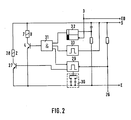
- FIG. 2 shows the line switching device 5 according to FIG. 1 in more detail. It contains in. essentially a flip-flop 32, two monoflops 33 and 29, an AND gate 31, the three inputs of which are connected to the output of the flip-flop 32 and to the negated outputs of the two monoflops 33 and 29, the relay U , 7, with a switching transistor 4 connected in series, the base of which is driven by the output of the AND gate 31, and the relay Z, 28 with a transistor 27, also connected in series, the base of which is driven by the standard output of the second monoflop 29.
- the circuit works as follows. If a connection is to be set up, voltage is applied to the line connection device via the control and power supply line S or the return line E. There the flip-flop 32 is set and the monoflop 33 is triggered. If the connection is busy, a pulse is generated by the speech loop test circuit 2 within 1.5 seconds after S is set, which pulse resets the flip-flop 32 via 3. If, on the other hand, the connection is free, the third input of the AND gate 31 is also set after the mono-flop 33 time has elapsed, as a result of which the switching transistor 4 is turned on by the output of the AND gate 31 and the changeover relay U is excited.
- the relay Z is switched off again and the changeover relay U is switched on accordingly.
- the arrangement according to the invention does not remain limited to a single earth key simulation, but, if the sequence control 10 is set accordingly, two earth key simulations separated by a defined pause can also be carried out for an outside office.
Abstract
Description
Die Erfindung betrifft eine Schaltungsanordnung zum Auf- bzw. Abbau einer Verbindung mit Hilfe einer Datenübertragungseinrichtung gemäß Oberbegriff des Hauptanspruchs.The invention relates to a circuit arrangement for setting up or clearing down a connection with the aid of a data transmission device according to the preamble of the main claim.
Solche Anordnungen sind bekannt geworden beispielsweise als Bildschirmtextmodem bei der Entwicklung und Planung des zukünftigen neuen Dienstes Bildschirmtext, wobei stellvertretend zitiert seien die deutschen Patentanmeldungen P 28 23 283, P 28 40 845, P 29 42 441 und der Aufsatz "Funktion der Teilnehmereinrichtungen für Bildschirmtext" von Bambach, Koeck, Schüssler in Fernmeldepraxis Bd. 56/1979 Nr. 24.Such arrangements have become known, for example, as a screen text modem in the development and planning of the future new service screen text, the German
Derartige Bildschirmtextmodems, die mit automatischer Wähleinrichtung versehen sind, gestatten zusammen mit einem Fernsehgerät, das für Bildschirmtextempfang eingerichtet ist, dem Inhaber oder Benutzer eines Fernsprechanschlusses den Konsum des neuen Dienstes Bildschirmtext über seine Fernsprechanschlußleitung, wobei Fernsprechen und Bildschirmtextempfang nur wahlweise möglich sind.Such screen text modems, which are provided with an automatic dialing device, together with a television set which is set up for screen text reception, allow the owner or user of a telephone connection to consume the new service screen text via his telephone connection line, whereby telephone and screen text reception are only possible.
Die Bildschirmtextmodems müssen aufgrund einer Forderung der Deutschen Bundespost eine netzunabhängige Stromversorgung aufweisen, sie werden deshalb über die Fernsprechanschlußleitung gespeist.The on-screen text modems have to have a mains-independent power supply due to a requirement of the German Federal Post Office, they are therefore fed via the telephone connection line.
Beim Aufbau einer Bildschirmtextverbindung können kurzzeitige Speisestromunterbrechungen bzw. -einbrüche auftreten, die dazu führen können, daß der Verbindungsaufbau gestört wird und evtl. vom Teilnehmer erneut gestartet werden muß. Je nach Verweildauer des einzelnen Teilnehmers in einem solchen Fall, können hierdurch wichtige Organe der Vermittlungseinrichtungen unnötig lange belegt werden. Besonders wichtig ist dieser Aspekt bei Einsatz von Bildschirmtextmodems in Nebenstellenwählanlagen.When establishing a screen text connection, brief interruptions in or interruption of the power supply can occur, which can lead to the connection establishment being disturbed and possibly having to be restarted by the subscriber. Depending on the length of time the individual subscriber stays in such a case, important organs of the switching facilities can be occupied unnecessarily long. This aspect is particularly important when using screen text modems in private branch exchanges.
Die Erfindung hat sich deshalb zur Aufgabe gestellt, eine Schaltungsanordnung der obengenannten Art anzugeben, die es bei kleinem Aufwand gestattet, nach Speisestromunterbrechungen den Aufbau einer Verbindung erfolgreich weiterzuführen oder selbsttätig einen neuen Aufbau zu starten.The object of the invention is therefore to provide a circuit arrangement of the type mentioned above which, with little effort, allows the connection to be successfully continued after supply current interruptions or a new structure to be started automatically.
Die Lösung dieser Aufgabe erfolgt mit den in den Patentansprüchen angegebenen Mitteln.This object is achieved with the means specified in the patent claims.
Zwar wurde schon vorgeschlagen, den Energiespeicher für die Stromversorgung der Datenübertragungseinrichtung zu vergrössern. Die erforderliche Vergrößerung würde jedoch mindestens eine bis zwei Größenordnungen betragen, um auch die langen, bis zu einigen Sekunden betragenden Stromunterbrechungen bei der Amtsanlassung in Nebenstellenanlagen zu überbrücken, und einen großen Platzbedarf beanspruchen. Auch wurde schon vorgeschlagen, die Datenübertragungseinrichtung vom Wechselspan~ nungsnetz zusätzlich mit Strom zu versorgen. Dies hat jedoch den Nachteil, daß aufwendige Blitzschutzmaßnahmen getroffen werden müssen.It has already been proposed to increase the energy storage for the power supply of the data transmission device. The required enlargement would, however, be at least one to two orders of magnitude in order to also bridge the long power interruptions of up to a few seconds when the office was started in private branch exchanges, and would take up a large amount of space. It has also already been proposed to additionally supply the data transmission device with power from the AC voltage network. However, this has the disadvantage that complex lightning protection measures must be taken.
Die erfindungsgemäße Lösung bietet die Vorteile, daß bei wenig Aufwand, unter Umgehung eines voluminösen Energiespeichers, in energiesparender Weise nach Unterbrechungen des speisenden Schleifenstromes der Aufbau einer Datenverbindung in kürzest möglicher Zeit erfolgreich zu Ende geführt oder neu gestartet wird, ohne daß zentrale Vermittlungseinrichtungen unnötig lange belegt sind.The solution according to the invention offers the advantages that, with little effort, bypassing a voluminous energy store, the establishment of a data connection is successfully completed or restarted in the shortest possible time in an energy-saving manner after interruptions of the feeding loop current, without central switching devices being occupied unnecessarily long are.
Im folgenden wird die Erfindung anhand der Figuren beschrieben.
- Die Fig. 1 zeigt ein Funktionsschaltbild eines Bildschirmtextmodems,
- die Fig. 2 weitere Einzelheiten der Leitungsanschalteinrichtung.
- 1 shows a functional circuit diagram of a screen text modem,
- 2 further details of the line switching device.
Der strichpunktierte Block der Fig. 1 umfaßt einen Bildschirmtextmodem, der auch für den Einsatz in Nebenstellenanlagen geeignet ist und der an die Adern a, b der Fernsprechanschlußleitung FAL und gegebenenfalls Erde angeschlossen ist, der über die Adern a', b' mit dem Telefonapparat 1 und der über die vier Leitungen Steuerung und Stromversorgung S, Empfangsdaten ED, Sendedaten SD und Rückleitung E mit der Datenendeinrichtung DEE (hier Bildschirmtextgerät) verbunden ist. Der Bildschirmtextmodem enthält die Leitungsanschalteinrichtung 5, die vom Bildschirmtextgerät gespeist wird, sowie die folgenden über die Fernsprechanschlußleitung FAL gespeisten Funktionsblöcke: Sprechschleifentesteinrichtung 2, Verpolungsschutz und Wählschalter 8, 9, Weiche 11, Stromversorgungsschaltung 13 zur Gewinnung der Versorgungsspannung aus dem Schleifenstrom, Ablaufsteuerung mit au-tomatischer Wähleinrichtung 10, 10a, Demodulator DEMOD, Modulator MOD, Multiplexeinrichtung MUX sowie Kennungs- und Telefonnummern-Speicher. Weitere für die Erfindung unwesentliche Blöcke sind in Fig. 1 nicht wiedergegeben.The dash-dotted block of FIG. 1 comprises a screen text modem which is also suitable for use in private branch exchanges and which is connected to the wires a, b of the telephone connection line FAL and possibly earth, which is connected to the telephone set 1 via the wires a ', b' and which is connected via the four lines of control and power supply S, received data ED, transmitted data SD and return line E to the data terminal device DEE (here screen text device). The screen text modem contains the
Die erfindungsgemäße Speichereinrichtung (22) zur Abspeicherung der Betriebszustände der Datenübertragungseinrichtung ist über einen Gleichrichter g und einen Ladekondensator C2 an den Ausgang der Stromversorgung 13 und über die Steuerleitungen NW, NW und Reset mit der Steuerung 10 verbunden.The storage device (22) according to the invention for storing the operating states of the data transmission device is connected to the controller 10 via a rectifier g and a charging capacitor C2 to the output of the
Die Funktionsweise der Schaltung ist folgende. Wenn durch Betätigung der Taste "Wählen" am Fernbedienungsgeber des Datenendgerätes DEE eine Verbindung aufgebaut werden soll, wird über die Leitung S Speisespannung an die Leitungsanschalteinrichtung 5 gelegt, die somit mittels Sprechschleifentesteinrichtung 2, deren Ausgang mittels Optokoppler an die zum Eingang der Leitungsanschalteinrichtung 5 führende Leitung 3 verbunden ist, feststellen kann, ob der Fernsprechanschluß belegt ist oder nicht. Bei belegtem Anschluß wird innerhalb von 1,5 Sekunden nach Setzen von S von der Sprechschleifentestschaltung 2 ein Signal erzeugt, das von der Leitungsanschalteinrichtung 5 zur Datenendeinrichtung DEE übertragen, dort ausgewertet wird und zur Abschaltung von S führt. Bei freiem Anschluß wird der Modem angeschaltet, indem ein Umschaltrelais U der Leitungsanschalteinrichtung 5 erregt wird und die Ader a über den Umschaltkontakt u des genannten Relais an den Schleifeneingang des Verpolungsschutzes 8 bzw. der Wählkontakteinrichtung nsi (9) gelegt wird. Nach Aufbau der Betriebsspannung erfolgt die Verbindungsaufbauprozedur, wobei nach einer kurzen Wartezeit durch die Steuerung 10 bzw. durch die Wähleinrichtung 10a die Ziffern einer oder gegebenenfalls mehrerer zehnstelligen Rufnummern aus dem Telefonnummern-Speicher bereitgestellt und Wählimpulse für den nsi-Kontakt erzeugt werden. Nach Abschluß des Verbindungsaufbaus werden verschiedene Hörtöne sowie Modemkennungen und Codewürter zwischen angewählter Bildschirmtextzentrale und Bildschirmtextmodem ausgetauscht und nach positivem Prüfungsergebnis ein Datentransfer ermöglicht.The circuit works as follows. If a connection is to be established by actuating the "Select" button on the remote control transmitter of the data terminal DEE, supply voltage is applied to the
Findet nun während des Verbindungsaufbaues eine Unterbrechung oder ein Einbruch des Schleifenstromes statt, so wird dies von der Stromversorgung 13 über die Leitung LU an die Steuerung 10 gemeldet, die eine kurze Zeit lang (in der Größenordnung 200 msec) durch den Kondensator C1 weiterversorgt wird. In dieser Zeit wird durch die Ablaufsteuerung 10 über die Leitung NW in der Speichereinrichtung 22 der betreffende Betriebszustandsspeicher gesetzt. Anschließend wird die Ablaufsteuerung 10 durch die Speichereinrichtung 22 über die Leitung Reset in einen definierten Grundzustand versetzt, um Fehlfunktionen infolge des Spannungszusammenbrüchs am Kondensator C1 bzw. an der Ablaufsteuerung 10 zu verhindern. Bei Spannungswiederkehr wird das Signal Reset durch die Speichereinrichtung 22 wieder zurückgenommen. Danach werden durch die Ablaufsteuerung 10 die Betriebszustandsspeicher der Speichereinrichtung 22 abgefragt und erstere in den eingespeicherten Ausgangsbetriebszustand zurückversetzt.If the loop current is interrupted or broken during the establishment of the connection, this is reported by the
In einer Ausgestaltung der Erfindung sind der Ladekondensator C2 und entsprechende Schaltmittel am Eingang der Speichereinrichtung 22, die vorteilhafterweise aus CMOS-Schaltkreisen besteht, so dimensioniert, daß die Betriebszustandsspeicher bei Überschreitung einer bestimmten einstellbaren Leitungsunterbrechungszeit (beispielsweise 10 sec.) automatisch in den Anfangsbetriebszustand zurückversetzt werden, wodurch ein erneuter Verbindungsaufbau ermöglicht wird.In one embodiment of the invention, the charging capacitor C2 and corresponding switching means at the input of the
Dies gestattet auch den Einsatz der erfindungsgemäßen Anordnung in Nebenstellenanlagen, bei denen vor der eigentlichen Wahl des Fernteilnehmers eine Amtsanlassung zu erfolgen hat. Dabei gibt es drei gebräuchliche Amtsanlässungsprozeduren:
- 1. Wahl einer oder mehrerer Kennziffern,
- 2. Betätigung einer Erdtaste,
- 3. Betätigung einer sog. Flashtaste.
- 1. choice of one or more codes,
- 2. pressing an earth button,
- 3. Actuation of a so-called flash key.
Zur Auswahl und Einstellung der entsprechenden Amtsanlassungsprozedur ist erfindungsgemäß eine Auswahlanordnung 20 vorgesehen. Diese Auswahlanordnung kann vorteilhafterweise als Auswahlmatrix mit Drahtbrücken oder Schaltern realisiert sein. Die Ablaufsteuerung 10 ist mit dieser Auswahlanordnung 20 verbunden und erzeugt bei einem Datenverbindungswunsch die entsprechenden Betriebszustandsschritte. Vorteilhafterweise ist die Steuerung 10 als Mikroprozessorsteuerung mit PROM- bzw. EPROM-Speicher realisiert, wodurch der Stromverbrauch des Modems sehr niedrig gehalten werden kann.According to the invention, a
Bei Einsatz des erfindungsgemäßen Modems in Nebenstellenanlagen mit der ersten Amtsanlassungsprozedur ist in einer Ausgestaltung ein Speicher 21 zur Einspeicherung von Kennziffern- bzw. Pausenfolgen vorgesehen. Die Kennziffern- bzw. Pausenfolgen können jedoch auch in dem an sich schon vorhandenen Speicher für Telefonnummern abgelegt werden, wodurch nur wenige zusätzliche Betriebszustandsschritte in der Ablaufsteuerung 10 erforderlich sind, da dann die Kennziffernvorwahl in der gleichen Weise wie die Wahl der Telefonnummer des Fernteilnehmers erfolgen kann.When using the modem according to the invention in private branch exchanges with the first initiation procedure, in one embodiment a
Bei Einsatz der erfindungsgemäßen Anordnung in Nebenstellenanlagen mit Amtsanlassung durch Erdtastenbetätigung, wobei die beiden Adern a und b mit Erde verbunden werden, sind zwei Relaisschaltkontakte z vorgesehen, die als Umschalte- bzw. Arbeitskontakte realisiert sein können.When using the arrangement according to the invention in private branch exchanges with official initiation by earth key actuation, the two wires a and b being connected to earth, two relay switch contacts z are provided, which can be implemented as changeover or work contacts.
In Fig. 1 ist eine Ausführung als Umschalter 23 gezeichnet. Die Relaiskontaktlösung wird deshalb einer Halbleiterstruktur beispielsweise einem selbstsperrenden Feldeffekttransistor oder einem VMOS-Element vorgezogen, weil erstens der Relaiskontakt ein idealer Kurzschlußkontakt mit einem Widerstand von < 1 Ω darstellt, weil zweitens das Problem des zusätzlichen Blitzschutzes für die Halbleiterlemente entfällt und drittens weil ein Relais gleichzeitig die erforderliche galvanische Trennung mit sich bringt, wenn sein Erregerstrom von der Leitungsanschalteeinheit 5 und damit vom Bildschirmtextgerät d. h. also nicht vom Amt geliefert wird,so daß ein zusätzlicher Optokoppler zwischen Amtsschleife und Leitungsanschalteeinheit 5 entfallen kann.In Fig. 1, an embodiment as a
Das oben Gesagte gilt ebenfalls für die Amtsanlassungsprozedur durch Flashtastenbetätigung, wodurch der Schleifenstrom eine definierte Zeit (beispielsweise 80 msec) unterbrochen wird. Diese Schleifenunterbrechung wird erfindungsgemäß ebenfalls mit einem Relaiskontaktpaar z durchgeführt, wobei bei der Realisierung als Umschaltekontaktblock 23 der Fig. 1 die Brücke 25 aufgetrennt werden muß.The above also applies to the office initiation procedure by flash key actuation, whereby the loop current is interrupted for a defined time (for example 80 msec). This loop interruption is also carried out according to the invention with a pair of relay contacts z, the
In Fig. 2 ist die Leitungsanschalteeinrichtung 5 nach Fig. 1 detaillierter dargestellt. Sie enthält im. wesentlichen ein Flip-Flop 32, zwei Monoflops 33 und 29, ein UND-Verknüpfungsglied 31, dessen drei Eingänge mit dem Ausgang des F'lip-Flops 32 bzw. mit den negierten Ausgängen der beiden Monoflops 33 und 29 verbunden sind, das Relais U, 7, mit einem in Reihe geschalteten Schalttransistor 4, dessen Basis durch den Ausgang des UND-Gliedes 31 angesteuert wird, und dem Relais Z, 28 mit einem ebenfalls in Reihe geschalteten Transistor 27, dessen Basis vom Normaiausgang des zweiten Monoflops 29 angesteuert wird.FIG. 2 shows the
Die Schaltung funktioniert wie folgt. Soll eine Verbindung aufgebaut werden, so wird über die Steuerung und Stromversorgungsleitiung S bzw. den Ruckleiter E Spannung an die Leitungsanschalteeeinrichtung gelegt. Dadurch werden das Flip-Flop 32 gesetzt und das Monoflop 33 getriggert. Bei belegtem Anschluß wird innerhalb 1,5 Sekunden nach Setzen von S von der Sprechschleifentestschaltung 2 ein Impuls erzeugt, der über 3 das Flip-Flop 32 zurücksetzt. Ist dagegen der Anschluß frei, so wird nach Ablauf der Mono-Flop-33-Zeit auch der dritte Eingang des UND-Gliedes 31 gesetzt, wodurch der Schalttransistor 4 vom Ausgang des UND-Gliedes 31 leitend gesteuert und das Umschaltrelais U erregt wird.The circuit works as follows. If a connection is to be set up, voltage is applied to the line connection device via the control and power supply line S or the return line E. There the flip-
Bei den Amstanlassungsprozeduren Erd- bzw. Flashtaste wird von der Ablaufsteuerung 10 über einen Optokoppler auf den negierten Eingang 26 des zweiten Mono-Flops 29 ein kurzer Trigger-Impuls gegeben, wodurch der Schalttransistor 27 durch den Ausgang des zweiten Mono-Flops 29 angesteuert und das Relais Z erregt wird. Gleichzeitig wird über den negierten Ausgang des zweiten Mono-Flops 29 die UND-Bedingung am UND-Verknüpfungsglied 31 aufgehoben, wodurch das Umschaltrelais U abfällt. Dies hat den Vorteil, daß der vom Bildschirmtextendgerät gelieferte Strom voll dem Erd- bzw. Flashtastensimulationsrelais Z zur Verfügung gestellt werden kann. Dies ist deshalb von großer Bedeutung, da auf der Steuerleitung S lediglich eine Spannung von 4 V zugelassen ist, wodurch die angebotene Schaltleistung eng begrenzt ist.In the initial start-up procedures earth or flash button is given a short trigger pulse by the sequencer 10 via an optocoupler to the negated
Nach Beendigung der mittels Kondensatoren und Brücken in einer Einstellvorrichtung 30 varriierbaren Schaltzeit des zweiten Mono-Flops 29, wird das Relais Z wieder ab- und das Umschaltrelais U entsprechend zugeschaltet.After the switching time of the second mono-
Selbstverständlich bleibt die erfindungsgemäße Anordnung nicht beschränkt auf eine einzige Erdtastensimulation, sondern es können bei entsprechender Einstellung der Ablaufsteuerung 10 beispielsweise auch zwei durch eine definierte Pause getrennte Erdtastensimulationen für eine Amtsanlassung durchgeführt werden.Of course, the arrangement according to the invention does not remain limited to a single earth key simulation, but, if the sequence control 10 is set accordingly, two earth key simulations separated by a defined pause can also be carried out for an outside office.
Claims (12)
Priority Applications (1)
| Application Number | Priority Date | Filing Date | Title |
|---|---|---|---|
| AT81104055T ATE6894T1 (en) | 1980-07-25 | 1981-05-27 | CIRCUIT ARRANGEMENT FOR UP OR. DISCONNECTING A DATA CONNECTION. |
Applications Claiming Priority (2)
| Application Number | Priority Date | Filing Date | Title |
|---|---|---|---|
| DE19803028236 DE3028236A1 (en) | 1980-07-25 | 1980-07-25 | CIRCUIT ARRANGEMENT FOR DISCONNECTING A DATA CONNECTION |
| DE3028236 | 1980-07-25 |
Publications (2)
| Publication Number | Publication Date |
|---|---|
| EP0044918A1 true EP0044918A1 (en) | 1982-02-03 |
| EP0044918B1 EP0044918B1 (en) | 1984-03-28 |
Family
ID=6108104
Family Applications (1)
| Application Number | Title | Priority Date | Filing Date |
|---|---|---|---|
| EP81104055A Expired EP0044918B1 (en) | 1980-07-25 | 1981-05-27 | Circuit for establishing and cleaning a data connection |
Country Status (6)
| Country | Link |
|---|---|
| US (1) | US4434326A (en) |
| EP (1) | EP0044918B1 (en) |
| AT (1) | ATE6894T1 (en) |
| CA (1) | CA1173181A (en) |
| DE (2) | DE3028236A1 (en) |
| DK (1) | DK156867C (en) |
Cited By (1)
| Publication number | Priority date | Publication date | Assignee | Title |
|---|---|---|---|---|
| FR2591835A1 (en) * | 1985-12-16 | 1987-06-19 | Ricoh Kk | DATA TRANSMISSION SYSTEM WITH LIMITATION IN TIME |
Families Citing this family (8)
| Publication number | Priority date | Publication date | Assignee | Title |
|---|---|---|---|---|
| US4591663A (en) * | 1983-11-17 | 1986-05-27 | Trad, Inc. | Servo-linearized opto-electronic analog interface |
| US4640988A (en) * | 1984-04-03 | 1987-02-03 | Robinton Products, Inc. | Telephone interrupter |
| US4571463A (en) * | 1984-06-01 | 1986-02-18 | Code-A-Phone Corporation | Method and system for automatically inserting at least one pause into means for memorizing a dialing sequence |
| US4654482A (en) * | 1984-10-15 | 1987-03-31 | Deangelis Lawrence J | Home merchandise ordering telecommunications terminal |
| US4698757A (en) * | 1984-11-15 | 1987-10-06 | International Business Machines Corp. | Terminal procedure for utilizing host processor log on and log off prompts |
| JPS62104356A (en) * | 1985-10-31 | 1987-05-14 | Ricoh Co Ltd | Facsimile equipment |
| KR930001641A (en) * | 1991-06-17 | 1993-01-16 | 정용문 | How to recover the call on restart of the Kitelephone system |
| JP3046229B2 (en) * | 1995-10-04 | 2000-05-29 | キヤノン株式会社 | Telephone equipment |
Citations (4)
| Publication number | Priority date | Publication date | Assignee | Title |
|---|---|---|---|---|
| US3959778A (en) * | 1973-09-05 | 1976-05-25 | Compagnie Honeywell Bull (Societe Anonyme) | Apparatus for transferring data from a volatile main memory to a store unit upon the occurrence of an electrical supply failure in a data processing system |
| DE2536200A1 (en) * | 1975-08-13 | 1977-02-24 | Standard Elektrik Lorenz Ag | Telephone voice line supply break monitor - uses transistor switched from divider by line potential |
| DE2814837B1 (en) * | 1978-04-06 | 1979-05-17 | Standard Elek K Lorenz Ag | Data modem, especially for teletext operation |
| EP0023695A1 (en) * | 1979-08-02 | 1981-02-11 | Siemens Aktiengesellschaft | Surveillance circuitry for an input voltage |
-
1980
- 1980-07-25 DE DE19803028236 patent/DE3028236A1/en not_active Withdrawn
-
1981
- 1981-05-27 EP EP81104055A patent/EP0044918B1/en not_active Expired
- 1981-05-27 AT AT81104055T patent/ATE6894T1/en not_active IP Right Cessation
- 1981-05-27 DE DE8181104055T patent/DE3162861D1/en not_active Expired
- 1981-07-10 DK DK307581A patent/DK156867C/en not_active IP Right Cessation
- 1981-07-24 US US06/286,584 patent/US4434326A/en not_active Expired - Fee Related
- 1981-07-24 CA CA000382549A patent/CA1173181A/en not_active Expired
Patent Citations (4)
| Publication number | Priority date | Publication date | Assignee | Title |
|---|---|---|---|---|
| US3959778A (en) * | 1973-09-05 | 1976-05-25 | Compagnie Honeywell Bull (Societe Anonyme) | Apparatus for transferring data from a volatile main memory to a store unit upon the occurrence of an electrical supply failure in a data processing system |
| DE2536200A1 (en) * | 1975-08-13 | 1977-02-24 | Standard Elektrik Lorenz Ag | Telephone voice line supply break monitor - uses transistor switched from divider by line potential |
| DE2814837B1 (en) * | 1978-04-06 | 1979-05-17 | Standard Elek K Lorenz Ag | Data modem, especially for teletext operation |
| EP0023695A1 (en) * | 1979-08-02 | 1981-02-11 | Siemens Aktiengesellschaft | Surveillance circuitry for an input voltage |
Non-Patent Citations (2)
| Title |
|---|
| CONTROL ENGINEERING, Band 25, Nr. 12, Dezember 1978, Seiten 84,85 New York, U.S.A. BEASTON: " Automatically restarting a microprocessor after power failure" * |
| TECHNISCHE MITTEILUNGEN AEG-TELE-FUNKEN, Band 69, Nr. 4, 1979, Seiten 136-140 Berlin, DE. BAMBACH et al.: "Bildschirmtext-Beschreibung des Teilnehmergerätesund der Datenübertragungseinrichtung" * |
Cited By (1)
| Publication number | Priority date | Publication date | Assignee | Title |
|---|---|---|---|---|
| FR2591835A1 (en) * | 1985-12-16 | 1987-06-19 | Ricoh Kk | DATA TRANSMISSION SYSTEM WITH LIMITATION IN TIME |
Also Published As
| Publication number | Publication date |
|---|---|
| CA1173181A (en) | 1984-08-21 |
| DK307581A (en) | 1982-01-26 |
| ATE6894T1 (en) | 1984-04-15 |
| DK156867B (en) | 1989-10-09 |
| EP0044918B1 (en) | 1984-03-28 |
| US4434326A (en) | 1984-02-28 |
| DK156867C (en) | 1990-02-26 |
| DE3028236A1 (en) | 1982-03-18 |
| DE3162861D1 (en) | 1984-05-03 |
Similar Documents
| Publication | Publication Date | Title |
|---|---|---|
| DE1762969B2 (en) | CIRCUIT ARRANGEMENT FOR DISPLAYING THE RATING CLASS IN REMOTE COMMUNICATION SYSTEMS | |
| EP0044918B1 (en) | Circuit for establishing and cleaning a data connection | |
| DE10253308B4 (en) | Process for commissioning a house communication system and house communication system to be put into operation with this process | |
| DE19630456B4 (en) | ISDN telephone | |
| DE416087C (en) | Circuit arrangement for telephone systems with dialer operation, in which registers are set by a calling station | |
| DE1924096C3 (en) | Circuit arrangement for establishing connections in a telephone system | |
| DE1292169B (en) | Circuit arrangement of a field office for the transmission of binary data between a central office and a plurality of these field stations arranged in a message loop | |
| DE3213217A1 (en) | Method and circuit arrangement for remote control of electrical devices | |
| EP0066668B1 (en) | Method of operating a telephone system | |
| DE878227C (en) | Automatic telephone system in which the dial setting is controlled by marker dials | |
| DE635284C (en) | Arrangement for automatic telephone systems | |
| DE2912744C2 (en) | Method for telephone and private branch exchange systems with cyclical scanning of connecting lines with the aid of a centrally arranged memory | |
| DE2743623C3 (en) | Electronically controlled telephone system with an electronic crosspoints having speech path through switching and Tonanschaltungkoppelmatrix, as well as with these associated stop sets | |
| DE3604753A1 (en) | Circuit arrangement for an electronic ripple-control receiver | |
| DE3310608A1 (en) | Circuit arrangement for a small dial-up PBX system | |
| DE1512100A1 (en) | Message switching system with control signal delay device | |
| DE3610730A1 (en) | Device for a secondary PABX system | |
| DE2748560C2 (en) | Circuit arrangement for telecommunications switching systems, in particular telephone switching systems, with connection-specific switching devices and sub-central control devices assigned to them | |
| DE965134C (en) | Circuit arrangement for encoders for setting dialers in telecommunications, in particular telephone systems | |
| EP0120459B1 (en) | Circuit arrangement for a small pbx with a switching device with electronic switching points | |
| DE19730295C2 (en) | Device for using convenience features of the telephone service on terminals connected via PABX to analogue dial-up connections of a telephone network | |
| DE1512062A1 (en) | Messaging system | |
| DE641061C (en) | Circuit arrangement for telecommunications, in particular self-connecting telephone systems | |
| DE1256265C2 (en) | CIRCUIT ARRANGEMENT FOR REMOTE COMMUNICATION SYSTEMS, IN PARTICULAR TELEPHONE SYSTEMS, WITH A COUPLING FIELD, EQUIPMENT FOR RECEIVING AND TRANSFERRING DIAL TAGS AND A CENTRAL MARKER | |
| DE3310562A1 (en) | Circuit arrangement for a small dial-up PBX system which can be used as a satellite PBX system |
Legal Events
| Date | Code | Title | Description |
|---|---|---|---|
| PUAI | Public reference made under article 153(3) epc to a published international application that has entered the european phase |
Free format text: ORIGINAL CODE: 0009012 |
|
| AK | Designated contracting states |
Designated state(s): AT BE CH DE FR GB LI LU NL SE |
|
| 17P | Request for examination filed |
Effective date: 19820225 |
|
| RAP1 | Party data changed (applicant data changed or rights of an application transferred) |
Owner name: AEG - TELEFUNKEN NACHRICHTENTECHNIK GMBH |
|
| RAP1 | Party data changed (applicant data changed or rights of an application transferred) |
Owner name: ANT NACHRICHTENTECHNIK GMBH |
|
| GRAA | (expected) grant |
Free format text: ORIGINAL CODE: 0009210 |
|
| AK | Designated contracting states |
Designated state(s): AT BE CH DE FR GB LI LU NL SE |
|
| REF | Corresponds to: |
Ref document number: 6894 Country of ref document: AT Date of ref document: 19840415 Kind code of ref document: T |
|
| REF | Corresponds to: |
Ref document number: 3162861 Country of ref document: DE Date of ref document: 19840503 |
|
| ET | Fr: translation filed | ||
| PLBE | No opposition filed within time limit |
Free format text: ORIGINAL CODE: 0009261 |
|
| STAA | Information on the status of an ep patent application or granted ep patent |
Free format text: STATUS: NO OPPOSITION FILED WITHIN TIME LIMIT |
|
| 26N | No opposition filed | ||
| R20 | Corrections of a patent specification |
Effective date: 19880406 |
|
| PGFP | Annual fee paid to national office [announced via postgrant information from national office to epo] |
Ref country code: GB Payment date: 19930511 Year of fee payment: 13 |
|
| PGFP | Annual fee paid to national office [announced via postgrant information from national office to epo] |
Ref country code: FR Payment date: 19930518 Year of fee payment: 13 |
|
| PGFP | Annual fee paid to national office [announced via postgrant information from national office to epo] |
Ref country code: SE Payment date: 19930527 Year of fee payment: 13 Ref country code: AT Payment date: 19930527 Year of fee payment: 13 |
|
| PGFP | Annual fee paid to national office [announced via postgrant information from national office to epo] |
Ref country code: NL Payment date: 19930531 Year of fee payment: 13 |
|
| PGFP | Annual fee paid to national office [announced via postgrant information from national office to epo] |
Ref country code: BE Payment date: 19930601 Year of fee payment: 13 |
|
| PGFP | Annual fee paid to national office [announced via postgrant information from national office to epo] |
Ref country code: LU Payment date: 19930602 Year of fee payment: 13 |
|
| PGFP | Annual fee paid to national office [announced via postgrant information from national office to epo] |
Ref country code: CH Payment date: 19930617 Year of fee payment: 13 |
|
| EPTA | Lu: last paid annual fee | ||
| PG25 | Lapsed in a contracting state [announced via postgrant information from national office to epo] |
Ref country code: LU Free format text: LAPSE BECAUSE OF NON-PAYMENT OF DUE FEES Effective date: 19940527 Ref country code: GB Effective date: 19940527 Ref country code: AT Effective date: 19940527 |
|
| PG25 | Lapsed in a contracting state [announced via postgrant information from national office to epo] |
Ref country code: SE Effective date: 19940528 |
|
| PG25 | Lapsed in a contracting state [announced via postgrant information from national office to epo] |
Ref country code: LI Effective date: 19940531 Ref country code: CH Effective date: 19940531 Ref country code: BE Effective date: 19940531 |
|
| PGFP | Annual fee paid to national office [announced via postgrant information from national office to epo] |
Ref country code: DE Payment date: 19940707 Year of fee payment: 14 |
|
| BERE | Be: lapsed |
Owner name: ANT NACHRICHTENTECHNIK G.M.B.H. Effective date: 19940531 |
|
| PG25 | Lapsed in a contracting state [announced via postgrant information from national office to epo] |
Ref country code: NL Effective date: 19941201 |
|
| NLV4 | Nl: lapsed or anulled due to non-payment of the annual fee | ||
| GBPC | Gb: european patent ceased through non-payment of renewal fee |
Effective date: 19940527 |
|
| EUG | Se: european patent has lapsed |
Ref document number: 81104055.9 Effective date: 19941210 |
|
| PG25 | Lapsed in a contracting state [announced via postgrant information from national office to epo] |
Ref country code: FR Effective date: 19950131 |
|
| REG | Reference to a national code |
Ref country code: CH Ref legal event code: PL |
|
| EUG | Se: european patent has lapsed |
Ref document number: 81104055.9 |
|
| REG | Reference to a national code |
Ref country code: FR Ref legal event code: ST |
|
| PG25 | Lapsed in a contracting state [announced via postgrant information from national office to epo] |
Ref country code: DE Effective date: 19960201 |