EP0111321A2 - Methods and apparatus for initializing the print wheels in an electronic postage meter - Google Patents
Methods and apparatus for initializing the print wheels in an electronic postage meter Download PDFInfo
- Publication number
- EP0111321A2 EP0111321A2 EP83112363A EP83112363A EP0111321A2 EP 0111321 A2 EP0111321 A2 EP 0111321A2 EP 83112363 A EP83112363 A EP 83112363A EP 83112363 A EP83112363 A EP 83112363A EP 0111321 A2 EP0111321 A2 EP 0111321A2
- Authority
- EP
- European Patent Office
- Prior art keywords
- print wheel
- moving
- rotating
- predetermined
- Prior art date
- Legal status (The legal status is an assumption and is not a legal conclusion. Google has not performed a legal analysis and makes no representation as to the accuracy of the status listed.)
- Granted
Links
Images


Classifications
-
- G—PHYSICS
- G07—CHECKING-DEVICES
- G07B—TICKET-ISSUING APPARATUS; FARE-REGISTERING APPARATUS; FRANKING APPARATUS
- G07B17/00—Franking apparatus
- G07B17/00459—Details relating to mailpieces in a franking system
- G07B17/00508—Printing or attaching on mailpieces
-
- G—PHYSICS
- G07—CHECKING-DEVICES
- G07B—TICKET-ISSUING APPARATUS; FARE-REGISTERING APPARATUS; FRANKING APPARATUS
- G07B17/00—Franking apparatus
- G07B17/00459—Details relating to mailpieces in a franking system
- G07B17/00508—Printing or attaching on mailpieces
- G07B2017/00516—Details of printing apparatus
- G07B2017/00524—Printheads
- G07B2017/00548—Mechanical printhead
Definitions
- the present invention relates to methods and apparatus for initializing print wheels of an electronic postage meter, and to electronic postage meters.
- the present invention relates broadly to electronic postage meters, for example to electronic postage meters of the stand-alone type such as disclosed in the aforementioned copending European application corresponding to U.S. Application Serial No.. 447,815.
- Known electronic postage meters have generally comprised two separate units like their earlier mechanical forerunners, i.e. a postage meter and base or mailing machine to enable the postage meter to be physically . taken to the post office periodically to charge the meter.
- a postage meter and base or mailing machine to enable the postage meter to be physically . taken to the post office periodically to charge the meter.
- Such a meter is disclosed in United States Letters Patent 4,301,507 issued on November 17, 1981 and assigned to Pitney Bowes, Inc. of Stamford, Connecticut. With the advent of remote meter resetting systems, it is no longer necessary that the postage meter be separated into two distinct units since the necessity to take the meter to the post office for recharging
- a program for use with the stand-alone postage meter of the present invention is disclosed in the accompanying Program Appendix.
- it is important during initial power up after power failure, or after unforeseen binding of the'meter components to relocate the print wheels to a known position for the subsequent setting of postage.
- a method and associated apparatus for initializing the print wheels in an electronic postage meter, comprising the steps of placing a print wheel selection mechanism in its select position, moving the print wheel selection mechanism into abutment with a stop a plurality of times, aligning the print wheel selection mechanism, orienting the print wheel selection mechanism with a predetermined one of the print wheels, rotating the print wheel into abutment with a stop a plurality of times, aligning the print wheel, exercising the print wheel to set it at a predetermined position, continuing the moving, aligning, orienting, and exercising steps sequentially with each print wheel to set all the print wheels to a predetermined position and outputting a signal when the foregoing steps have all been accomplished.
- the force by which the print wheel selection mechanism or print wheel is moved into abutment with a stop may be increased as desired.
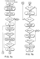
- FIGURE 7 formed from partial Figures 7a and 7b is a flow chart of a Postage Selection Routine.
- the electronic postage meter includes Referring to Figure 1, the electronic postage meter includes an 8-bit microprocessor 10 (CPU), such as an Intel Model 8085A microprocessor which is connected to various components through a system bus 12.
- ROM 14 is connected to the microprocessor 10 through the system bus 12.
- the ROM 14 stores the programs for controlling the postage meter. It should be understood that the term ROM as used herein includes permanently programmed and reprogrammable devices.
- An integrated circuit 16, which may be Intel Model 8155, is connected to the system bus 12 and includes RAM, input and output lines and a timer.
- the RAM portion of the intergrated circuit 16 has memory space allocated for transient storage of the data for the ascending register and descending register.
- An external data communication port 18 is connected to the microprocessor 10 through optical isolator 20
- the external data communication port 18 allows connection with devices such as an electronic scale, an external computer, servicing equipment and the like.
- Also electrically connected to the microprocessor 10 through the system bus 12 is the keyboard 22 of the postage meter and a non-volatile memory (NVM) 24.
- Stepper motors 26, 28 are also in electrical connection with the microprocessor 10 via motor drivers 30 and the integrated circuit 16.
- a reset and power control 32 is electrically connected between the integrated circuit 16, the NVM 24 and the microprocessor 10.
- a relay 34 connects the AC printer motor 36 to the integrated circuit 16.
- a display 38 is also electrically connected to the integrated circuit 16.
- Trip photosensor 40 is connected to the microprocessor 10 through integrated circuit 16 to indicate the presence of an envelope to be stamped, as described more fully in the aforementioned copending European patent application corresponding to the U. S. applicaticn entitled Stand-Alone Electronic Mailing Machine".
- the electronic postage meter is controlled by the micropro- cessor 10 operating under control of the programs stored in the ROM 14.
- the microprocessor 10 accepts information entered via the keyboard 22 or via the external communication port 18 from external message generators.
- Critical accounting data and other important information is stored in the non-volatile memory 24.
- the non-volatile memory 24 may be an MNOS semiconductor type memory, a battery augmented CMOS memory, core memory, or other suitable non- volatile memory component.
- the non-volatile memory 24 stores critical postage meter data during periods when power is not applied to the postage meter.
- This data includes in addition to the serial number of the mailing machine or postage meter information as to the value in the descending register (the amount of postage available for printing), the value in the ascending register (the total amount of postage printed by the meter), and the value in the piece count register (the total number of cycles the meter has performed), as well as other types of data, such as trip status, initialization and service information, which are desired to be retained in the memory even though no power is applied to the meter.
- a power supply internal to the mailing machine energizes the microprocessor 10 and the balance of the electronic components.
- the information stored in the non-volatile memory 24 is transferred via the microprocessor 10 to the RAM of the integrated circuit 16.
- the RAM contains an image or copy of the information stored in the non-volatile memory 24 prior to energization.
- certain of the data in the RAM is modified. Accordingly, when postage is printed, the descending register will be reduced by the value of the printed postage, the ascending register increased by the value of the printed postage and the piece counter register incremented.
- the updated data in the RAM is transferred via the microprocessor 10 back into a suitably prepared area of the non-volatile memory 24. A like transfer of information between the non-volatile memory 24 and the RAM takes place during power failure.
- FIG. 48 a more detailed block diagram of the arrangement of the electrical components for the postage meter is illustrated generally as 48.
- Power is supplied to the postage meter from the AC line voltage, typically 115 volts.
- This line voltage is applied to the meter through a hot switch 50 which cuts off power to the postage meter to protect the electrical components thereof if the temperature rises above a preset limit, nominally 70°C.
- the hot switch 50 is connected to the AC drive motor 36A through an RF filter 52 and an opto-triac 54 -which provides isolation between the line voltage and the control logic for the meter.
- the hot switch 50 is also connected to a transformer 56 protected by a fuse 58.
- the output of the transformer 56 is coupled to a pre-regulator 59 through a cold switch 60.
- the cold switch 60 cuts off power to the pre-regulator 59 if the temperature drops below a preset limit, nominally 0°C.
- the pre-regulator 59 provides an output voltage of . a predetermined range to a switcher 62 which generates the output voltage +5V; and the voltages for generating -12V and -30V.
- the +5V is applied to a +3 volt regulator 64 and then to the display 38A.
- the +5V from the switcher 62 is also applied to a +5V filter 66 which provides +5V for loqic circuits.
- the +5V is applied to the keyboard 22A, the display 38A, and bank, digit and trip sensor logic 68 and to the integrated circuits.
- the -12V is applied to a -12V regulator 70 and then to the non-volatile memory 24A.
- the -30V output from the switcher 62 is also applied to a of-30V regulator 74 and then to a -30V switch 76 which switches its output voltage on and off in response to the requirements of writing in NVM as dictated by the program.
- the output of the -30V switch is applied to the non-volatile memory 24A.
- the -30V supply is connected to the power on reset 72 of the microprocessor in 10A.
- suitatabl +5V from the switcher 62 is also supplied to one input of the power on reset 72; the other input receives -30V from the regulator 74 as previously described.
- a low voltage sensor 88 also receives one input of +5V from the switcher 62 and its other input from the pre-regulator 59; its output is applied to the microprocessor 10A. The low voltage sensor 88 detects power failure and communicates this to the microprocessor 10A which in turn addresses the RAM through system bus 12A to transfer all security data present in the RAM to the non-volatile memory 24A.
- Another output from the pre-regulator 59 in the form of +24V is applied to the digit and bank motor drive 30A for the bank motor 26A and digit motor 28A, which selects the particular printing wheel (bank) which is to be activated and the particular digit of the selected printing wheel which is to be set.
- An output strobe from the integrated circuit 16A is buffered through buffer driver 68 and applied to digit sensor (encoder) 78, bank sensor (encoder) 80, and trip sensor 40A.
- the opto strobe applies power to the digit sensor 78, bank sensor 80 and trip sensor 40A When needed.
- the output from the trip sensor 40A is applied to the input/output lines 82 which are coupled to the integrated circuit 16A .
- the outputs from the digit sensor 78 and bank sensor 80 and cycle switch 84 are applied to a storage buffer 86.
- initialization may include a hard and/or soft initialization process as'disclosed in the aforementioned United States Letters Patent 4,301,507.
- the microprocessor 10A under control of the ROM 14A and possibly the auxiliary ROM 100 communicates over the address bus 94 and control bus 98 with the device select 98.
- the output of the device select 98 communicates with the particular module to be addressed over select lines 99.
- the modules to be addressed are the RAM, the ROM 14A, an auxiliary ROM 100, a demultiplexer 102, NVM logic 104 and the buffer 86.
- the RAM of integrated circuit 16A provides the working memory for the postage meter and the microprocessor 10A.
- the ROM 14A stores the program; the auxiliary ROM 100 may be used to provide additional program storage space.
- the non-volatile memory 24A provides storage of all security information for the meter and retains.such information during power down or power failure.
- the demultiplexer 102 latches the lower eight (8) bits of address information that defines a particular location which is used immediately thereafter.
- the NVM logic 104 controls the mode of operation of the NVM 24A and also provides ready wait and NVM ready signals to the microprocessor 10A to indicate the presence of the slow speed device (NVM) as active on the bus 12A.
- NVM slow speed device
- the digital sensor 78 (optical) encoder) and bank sensor 80, (optical encoder) and cycle switch 84 whose current state is read, i.e., "Home” or "In Cycle", apply input signals to the buffer 86 which sends output signals over data bus 108 to the microprocessor 10A for storage in the proper RAM location.
- the RAM is also electrically coupled to I/O lines to transmit or receive data from the trip sensor 40A, the display 33A, keyboard 22A, and privilege access switch 110, if present.
- the privilege access switch 10 may be used in applications which require manual resetting of meter postage via a switch which is kept under seal.
- a print wheel selection mechanism for an electronic postage meter of the type disclosed in the aforementioned copending European patent application corresponding to the U.S. application entitled “Stand-Alone Electronic Mailing Machine”, is illustrated generally as 140, 182 and 185, respectively. Further details regarding the print wheel selection mechanism and the other mechanical components of such an electronic postage meter may be obtained from said aforementioned patent application, the disclosure of which is incorporated by reference as previously noted.
- the print wheel selection mechanism 140 includes a trip lever 142 affixed to a rotatable trip shaft.144 adjacent to one end thereof for engagement and disengagement with a clutch 145.
- the trip shaft 144 also includes.a gear 146, see Fig. 4, affixed thereto for engagement with and rotation by a gear 148 affixed to a tri-lobed shaft 150.
- a stepper motor 28A includes an output shaft 152 having a gear .154 and an optical encoder disk 156 (not to scale) mounted on the output shaft 152.
- the optical encoder disk 156 is received within a sensor 158 so that the position of the stepper motor shaft 152 can be determined.
- the gear 154 engages a gear 157 affixed to the tri-lobed shaft 150.
- the gear 148 is disposed within an opening of a carriage 160.
- Another stepper motor 26a has a gear 168 mounted on its output shaft 170.
- An optical encoder disk 172 is also mounted on the output shaft 170 for determining the angular position of the gear 168 and output shaft 170.
- An optical sensor 174 receives the optical encoder disk 172 therein.
- the stepper motor 28A is energized to rotate the stepper motor gear 154 and the gear 157 affixed to the tri-lobed shaft 150.
- rotation of the tri-lobed shaft 150 rotates gear 146 affixed to the trip shaft 144 which rotates a locking lever 162 affixed to the trip lever shaft 144 out of engagement with a carriage slot 164, thereby freeing the carriage 160 for movement along the tri-lobed shaft .150.
- the trip shaft 144 and trip lever 142 are i their home or middle position.
- the down position of the trip lever 142 is the set position.
- the up position of the trip lever 142. is the trip position.
- the individual digit or font 192 of the desired print wheel 194 is then selected by the stepper motor 28A which rotates the tri-lobed shaft 150 and thus gear 148 which is engageable with the upper teeth 196 of a selected one of four print wheel racks 198..
- The. gear 148 is engageable with the upper teeth 196 of one of the four racks 198 which racks 198 have lower teeth 200 on their opposite end.
- the lower teeth 200 of each of the racks 198 engage gears 202 that are integral with their respective print wheels 194. That is, there is a corresponding print wheel 194 and associated gear 202 for each of the four racks 198.
- the four print wheels 194 have fonts 192 distributed about their peripheries: each print wheel 194 having ten fonts 192 representing the digits 0 to 9.
- the trip lever 142 and print wheel selection mechanism are in the lock position.
- soft an initialization from a known position
- hard initialization from an unknown position
- the trip lever 142 is moved downwardly to its set or select position thereby freeing the locking lever 162 from the slot 164 to allow movement of the carriage 160.
- the print wheel selection mechanism including the carriage 160, is then moved to the right to the limit of its range of movement until it abuts against framework 180. Two additional tries to move past this framework abutment 180 are made.
- the print wheel selection mechanism including the carriage 160, is then aligned with its last legitimate position by the optical encoder disk ' 172, sensor 174 and stepper motor 26a, and moved four (4) positions for alignment with the left most or first channel of racks 198. Thereafter, the first print wheel 194 associated with the first rack 198 is set to zero. The print wheel selection mechanism is then moved one position to the right to the second channel of racks 198 and the second print wheel 194 associated there with is set to zero. This procedure is repeated sequentially with the third and fourth print wheels 194 mtil all the print wheels are aligned at the position 0000.
- a soft initialization of the type described in the aforementioned United States Letters Patent 4,301,507 occurs on each power up subsequent to the initial power up of the eter unless there was a power failure during postage, selection, power failure during soft initialization, or unforeseen binding the meter components after which a hard initialization will occur. .at is, a soft initialization will occur if the power was turned of in a.stable state. Otherwise, a hard initialization will occur.
- the print wheels are individually exercised from their existing position until they all reach their maximum digit position, i.e., all 9s, and then rotated individually back to their minimum digit positions, i.e., all Os.
- Optical encoder sensors indicate the position of the print wheels. Signals from these sensors are sent to the microprocessor for indicating on the display that the meter is now in condition for the new postage value to be selected, see Fig. 7.
- gear 148 is meshing with gear 146, see Fig. 4. Therefore, the print wheel selection mechanism is in the select, lock and trip channel as shown in Figs. 3 and 4. Two, the gear 148 is meshing with one of the racks 198, see Fig. 5. Three, the gear 148 is: in between the racks 198.
- the stepper motor 28a first rotates the gear 148 towards the select position, i.e., corresponding with the select position of the trip lever 142, one (1) increment or position at a time unt it cannot rotate any farther. This fact is confirmed through a predetermined number of repetitive attempts, e.g., three times.
- the gear 148 is then aligned by the stepper motor 28a, optical encoder disk 156 and sensor 158 until the print wheel selection mechanism 140 is in the select position.
- condition Two exists, the digit stepper motor 28a first rotates the print wheel 194 associated with the rack 198 which is in mesh with gear 148 one (1) increment or position at a time until it abuts a stop beyond the maximum digit (cannot rotate any further). This is repeated three (3) times. The gear 148 is then aligned by the stepper motor 28a.
- condition Three the interposer teeth 183, see Fig. 4, engage the racks 198 preventing rotation of the gear 148.
- the bank stepper motor 26a first moves the gear 148 to a rack 198 and then the digit stepper motor 28a rotates the print wheel 194 associated with that rack 198 as described with reference to condition Two.
- the print wheel selection mechanism including the carriage 160 is moved in one direction (to the right in Fig. 3) by the bank motor 26a one (1) increment or position at a time until it reaches an obstruction. Two more attempts are made to move past the obstruction. It is then concluded that the print wheel selection mechanism is at one end of the limit of its ranqe of movement, i.e., abutting framework 180. Sensor 174 then aligns the print wheel selection mechanism to its last legitimate unobstructed position. To verify this position, the orint wheel selection mechanism is then moved in a direction towards the other extreme position of the print wheel selection mechanism four (4) positions.
- the select and lock positions are in the middle channel and two sets of print wheels 192 are located on each side thereof for engagement with four racks 198, resulting in five (5) possible positions within the extremes of the range of movement of the print'wheel selection mechanism.
- the only condition when the print wheel selection mechanism can move four positions in the direction towards the opposite extreme is if it is in the channel for the first print wheel.
- the print wheel selection mechanism for the digit motor is positioned, i.e., what digit is selected.
- the print wheel 192 under control of the digit motor 28a is moved one step or increment at a time to the upper limit in its range of movement until the movement fails after a total of three (3) attempts.
- the print wheel is then aligned with its last legitimate position by moving digit motor 28a slightly backward or forward.
- the motor rotates the print wheel nine (9) positions forward to its lowest digit to arrive at the position OXXX. If it does not arrive at the position OXXX, the entire process is repeated. The process is repeated a maximum of three times; if not successful, a fatal error bit is sent to the non-volatile memory 24a.
- the bank motor 26a then moves the print wheel selection mechanism one position to the right (position of :i..second print wheel .194) and the digit motor 28a then moves the second print wheel 194 into engagement with its mechanical block or stop, aligns it at the last legitimate position (digit 9), then rotates it forward to establish the position OOXX as explained above.
- the bank motor 26a then moves the print'wheel selection mechanism two positions to the right (skipping the select, lock and trip channel) and the digit motor 28a then moves the third print wheel 194 up into engagement with its mechanical block or stop, aligns it at the last legitimate position (digit 9) and then rotates it forward to establish the position OOOX.
- the bank motor 26a moves the print wheel selection mechanism one . position to the right and then the digit motor 28a rotates the fourth print wheel up into engagement with its mechanical block or stop, aligns it at the last legitimate position (digit 9) and then rotates it nine (9) positions forward to establish the position 0000.
- the print wheel selection, mechanism is then moved two channels to the left to arrive at the select channel and the digit motor 28a is moved a specified number of steps to position the trip lever 142 in the lock condition.
- a flag or bit is then sent to the working memory (RAM 16a) to indicate that the Hard Initialization process has been completed.
- the Hard Seek Routine for accomplishing the Hard Initialization is illustrated as 210.
- the digit and bank motors 28a and 26a are aligned to their home positions via digit and bank motor sensors 158 and 174, respectively.
- the digit stepper motor 28a rotates the gear 148 one position at a time until a stop is encountered. This is repeated two more times.
- the digit motor 28a is then aligned to its last legitimate position.
- the bank stepper motor 26a then moves the gear 148 and carriage 160 one position to the right, see Fig. 3. Movement of the carriage 160 is continued until the stop 180 is encountered. Two more attempts are made to move past the stop 180.
- the print wheel selection mechanism is..at its extreme range of movement.
- the bank motor 26a is then aligned to its last legitimate position.
- the print wheel selection mechanism is then moved four (4) positions to the left.. If the move is successful, the index or channel position is then set at one (1). If unsuccessful, the process starts over. If the move is successful, the print wheel 194 is moved (1) position towards its maximum digit. If that move is successful, movement of the print wheel 194 is further continued until a mechanical abutment occurs. Three attempts are made to move past the abutment. It is then concluded that the print wheel 194 is at its extreme ranqe of movement.
- the digit motor 28a is aligned to its last legitimate position.
- the print wheel 194 is then rotated nine (9) positions to its zero digit. If the move is not successful, RETRY is executed. If the move is successful, the print wheel selection mechanism is moved one position to the left to the next channel or rack. If the move is not successful, RETRY is executed. With a successful move, the index is changed by one. When the index becomes equal to three (3) (select, lock and trip channel position), this position is skipped and the index is changed by one. with the index equal to four (4) and five (5), ' the positions of the third and fourth racks or channels, respectively the same procedures are repeated as with the first and second print wheels.
- the print wheel selection mechanism is moved to home, i.e., select lock and trip channel. If the move to home is okay, the digit motor 28a moves the trip lever 142 to the lock position. If this move is okay, the Routine stops. If this move is not okay, RFTRY is executed.
- the alignment provided by the hard initialization of the present invention permits assembly of the postage meter with adjustments being done on the fly as required. This eliminates the need to make precise adjustments of the stepper motors, sen- sors and encoder disks during manufacture with an attendant reduction in manufacturing costs. Moreover, the digit motor 28a achieves precise positioning by utilizing a six (6) incremental movement for each digit in contrast with prior initialization techniques such as those disclosed in the aforementioned 26 United States Letters Patent 4,301,507, which utilized a four (4) . step incremental movement for each digit.
- the Postage Selection Routine illustrated as 220 may be implemented. This routine begins with a computation between the present value at which the print wheels are set, and the new postage value. The trip lever 142 and print wheel selection mechanism is then moved from the lock to the select position. If the move is not okay, a fatal error is logged in non-volatile memory and the routine is ended. If the move is okay, the channel position (rack) is set at one (1). The print wheel selection mechanism is then moved to the position of the first rack. If the setting of the print wheels 194 at each rack 198 is okay, the channel position (rack) is then changed by one (1).
- the print wheel selection mechanism When the channel number (rack) is equal to six (6), the print wheel selection mechanism is moved home. If the setting of the print wheels 194 at each rack 198 is not okay, the digit motor is energized to rotate the print wheel 194 to make up the differential. If the movement of each print wheel" 194 is okay, the channel position is incremented by one (1); channel three (3) is skipped. If the movement caused by the digit motor 28a or bank motor 26a is not okay, a fatal error is logged in non-volatile memory 24a and the routine is ended.
- the algorithm underlying the program set forth in the Program Appendix provides increased power to the bank motor 26a and digit motor 28a when an unforeseen mechanical obstruction or bind is encountered.
- the bank motor 26a and digit motor 28a both of which include four windings, have only one (1) of their windings energized and operate as a single phase drive.
- additional power is applied to the desired motor 26a or 28a by energizing a second winding, using a two phase drive for the subsequent attempts to move past the obstruction.
- the algorithm de-energizes the second winding of the motor 28a or 26a and the respective motor 28a or 26a shifts back to a single phase drive. This conserves power and minimizes the effect of increasing the power on the electrical components. It should also be understood that power to the motors 26a or 28a may be increased prior to encountering a stop. That is, in anticipation of a stop.
- the algorithm can cause the torque of the motors 26a or 28a to increase by reducing the stepping rate of the motors 26a or 28a.
- the reduction in the stepping rate allows more time for current build up in the windings of the motors 26a or 28a to increase the torque and overcome any possible resistance by stress imparted to the mechanical components due to aging.
- the stepping rate of the digital motor 28a is reduced since the digital motor 28a must drive the trip lever 142 to the trip position to enable the drive mechanism for printing postage on an envelope. It should also be understood that both the power and torque to the motors 26a and 28a may be increased as described above.
- postage meter refers to the general class of device for the imprinting of a defined unit value for governmental or private carrier delivery of parcels, envelopes or other like application for unit value printing.
- postage meter is utilized, it is both known and employed in the trade as a general term for devices utilized in conjunction with services other than those exclusively employed by governmental postage and tax services.
- private, parcel and freight services purchase and employ such meters as a means to provide unit value printing and accounting for individual parcels.
Abstract
Description
- The present invention relates to methods and apparatus for initializing print wheels of an electronic postage meter, and to electronic postage meters.
- The present application is related to the copending European pataent application of even date corresponding to U.S. Application Serial No. 447,815 in the name of Danilo Buan and entitled "Stand-Alone Electronic Mailing Machine", the disclosure of which is hereby incorporated herein by this reference.
- A program listing for use in the electronic postage meter disclosed in this application and in the aforementioned related patent application is set forth as part of this specification at the end of the detailed description and before the claims.
- The present invention relates broadly to electronic postage meters, for example to electronic postage meters of the stand-alone type such as disclosed in the aforementioned copending European application corresponding to U.S. Application Serial No.. 447,815.
- Known electronic postage meters have generally comprised two separate units like their earlier mechanical forerunners, i.e. a postage meter and base or mailing machine to enable the postage meter to be physically . taken to the post office periodically to charge the meter. Such a meter is disclosed in United States Letters Patent 4,301,507 issued on November 17, 1981 and assigned to Pitney Bowes, Inc. of Stamford, Connecticut. With the advent of remote meter resetting systems, it is no longer necessary that the postage meter be separated into two distinct units since the necessity to take the meter to the post office for recharging
- has been eliminated. Further, it is desirable to have a self- contained electronic postage meter that includes the metering function as well as all drive mechanisms to reduce the size and weight of the meter as well as making it more economical to produce. The mechanical construction of such a meter is disclosed in the aforementioned European patent application. U.S. Letters Patent 4,251,874, issued on February 17, 1979 in the name of Frank T Check, Jr., entitled, ELECTRONIC POSTAGE METER SYSTEM, and assigned to Pitney. Bowes, Inc., of Stamford, Connecticut, discloses a system for keeping track of the number of errors present during meter operation, and the disclosure thereof is also incorporated hereby into this specification.
- A program for use with the stand-alone postage meter of the present invention is disclosed in the accompanying Program Appendix. In such a meter, as well as in other programmable electronic postage meters, it is important during initial power up after power failure, or after unforeseen binding of the'meter components to relocate the print wheels to a known position for the subsequent setting of postage.
- It is an object of the present invention to provide initialization of the print wheels in an electronic postage meter.
- It is a further object of the present invention to provide for initialization of the print wheels from an unknown setting position in an electronic postage meter.
- It is a further object of the present invention to provide a procedure to relocate the print wheels of an electronic postage meter from a known starting position.
- It is a still further object of the present invention to provide for initializing the print wheels of an electronic postage meter when power is initially applied to the postage meter.
- It is a still further object of the present invention to provide for initializing the print wheels of an electronic postage meter after a power failure.
- It is a still further object of the present invention to provide for initializing the print wheels of an electronic postage meter after unforeseen binding of the meter components.
- It is a still further object of the present invention to implement the initialization with stepper motors whose speed and torque may be varied to overcome mechanical obstructions or unforeseen binding of the mechanical components.
- It is a still further object of the present invention to provide an initialization technique for the print wheels of an electronic postage meter which minimizes manufacturing costs by providing for alignment on the fly.
- and Briefly, a method and associated apparatus is provided for initializing the print wheels in an electronic postage meter, comprising the steps of placing a print wheel selection mechanism in its select position, moving the print wheel selection mechanism into abutment with a stop a plurality of times, aligning the print wheel selection mechanism, orienting the print wheel selection mechanism with a predetermined one of the print wheels, rotating the print wheel into abutment with a stop a plurality of times, aligning the print wheel, exercising the print wheel to set it at a predetermined position, continuing the moving, aligning, orienting, and exercising steps sequentially with each print wheel to set all the print wheels to a predetermined position and outputting a signal when the foregoing steps have all been accomplished. Advantageously, the force by which the print wheel selection mechanism or print wheel is moved into abutment with a stop may be increased as desired.
- Other objects, aspects and advantages of the present invention will be apparent when the detailed description is considered . with the preferred embodiment of the invention illustrated in the drawings, in which:
- FIGURE 1 is a block diagram of a general electronic circuit for a stand-alone electronic postage meter;
- FIGURE 2 formed from partial Figures 2a and 2b is a detailed block diagram of an electronic circuitry for a stand-alone electronic postage meter;
- FIGURE 3 is a plan view of the print wheel selection mechanism for a postage meter utilizing the present invention;
- FIGURE 4 is a side elevation of the locking mechanism for the print wheels;
- prov FIGURE 5 is a detailed cross sectional view of the print wheel selection mechanism operative on a print wheel;
-
initiFIGURE 6 formed from partial Figures 6a to 6d is a flow chart of a HARD SEEK Routine illustrating the present invention; and - FIGURE 7 formed from partial Figures 7a and 7b is a flow chart of a Postage Selection Routine.
- Referring to Figure 1,the electronic postage meter includes Referring to Figure 1, the electronic postage meter includes an 8-bit microprocessor 10 (CPU), such as an Intel Model 8085A microprocessor which is connected to various components through a
system bus 12. ROM 14 is connected to themicroprocessor 10 through thesystem bus 12. The ROM 14 stores the programs for controlling the postage meter. It should be understood that the term ROM as used herein includes permanently programmed and reprogrammable devices. An integratedcircuit 16, which may be Intel Model 8155, is connected to thesystem bus 12 and includes RAM, input and output lines and a timer. The RAM portion of the intergratedcircuit 16 has memory space allocated for transient storage of the data for the ascending register and descending register. An externaldata communication port 18 is connected to themicroprocessor 10 throughoptical isolator 20 The externaldata communication port 18 allows connection with devices such as an electronic scale, an external computer, servicing equipment and the like. Also electrically connected to themicroprocessor 10 through thesystem bus 12 is thekeyboard 22 of the postage meter and a non-volatile memory (NVM) 24. Stepper motors 26, 28 are also in electrical connection with themicroprocessor 10 viamotor drivers 30 and the integratedcircuit 16. A reset and power control 32 is electrically connected between the integratedcircuit 16, theNVM 24 and themicroprocessor 10. Arelay 34 connects theAC printer motor 36 to the integratedcircuit 16. Adisplay 38 is also electrically connected to the integratedcircuit 16.Trip photosensor 40 is connected to themicroprocessor 10 through integratedcircuit 16 to indicate the presence of an envelope to be stamped, as described more fully in the aforementioned copending European patent application corresponding to the U. S. applicaticn entitled Stand-Alone Electronic Mailing Machine". - The electronic postage meter is controlled by the micropro-
cessor 10 operating under control of the programs stored in the ROM 14. Themicroprocessor 10 accepts information entered via thekeyboard 22 or via theexternal communication port 18 from external message generators. Critical accounting data and other important information is stored in thenon-volatile memory 24. Thenon-volatile memory 24 may be an MNOS semiconductor type memory, a battery augmented CMOS memory, core memory, or other suitable non- volatile memory component. Thenon-volatile memory 24 stores critical postage meter data during periods when power is not applied to the postage meter. This data includes in addition to the serial number of the mailing machine or postage meter information as to the value in the descending register (the amount of postage available for printing), the value in the ascending register (the total amount of postage printed by the meter), and the value in the piece count register (the total number of cycles the meter has performed), as well as other types of data, such as trip status, initialization and service information, which are desired to be retained in the memory even though no power is applied to the meter. - When an on/off power switch 42 is turned on (closed) a power supply internal to the mailing machine energizes the
microprocessor 10 and the balance of the electronic components. The information stored in thenon-volatile memory 24 is transferred via themicroprocessor 10 to the RAM of theintegrated circuit 16. After power up the RAM contains an image or copy of the information stored in thenon-volatile memory 24 prior to energization. During operation of the postage meter, certain of the data in the RAM is modified. Accordingly, when postage is printed, the descending register will be reduced by the value of the printed postage, the ascending register increased by the value of the printed postage and the piece counter register incremented. When the power switch 42 is turned off (opened), the updated data in the RAM is transferred via themicroprocessor 10 back into a suitably prepared area of thenon-volatile memory 24. A like transfer of information between thenon-volatile memory 24 and the RAM takes place during power failure. - Referring to Figure 2, a more detailed block diagram of the arrangement of the electrical components for the postage meter is illustrated generally as 48. Power is supplied to the postage meter from the AC line voltage, typically 115 volts. This line voltage is applied to the meter through a
hot switch 50 which cuts off power to the postage meter to protect the electrical components thereof if the temperature rises above a preset limit, nominally 70°C. Thehot switch 50 is connected to the AC drive motor 36A through anRF filter 52 and an opto-triac 54 -which provides isolation between the line voltage and the control logic for the meter. Thehot switch 50 is also connected to a transformer 56 protected by afuse 58. The output of the transformer 56 is coupled to a pre-regulator 59 through a cold switch 60. The cold switch 60 cuts off power to the pre-regulator 59 if the temperature drops below a preset limit, nominally 0°C. The pre-regulator 59 provides an output voltage of . a predetermined range to aswitcher 62 which generates the output voltage +5V; and the voltages for generating -12V and -30V. The +5V is applied to a +3volt regulator 64 and then to the display 38A. The +5V from theswitcher 62 is also applied to a +5V filter 66 which provides +5V for loqic circuits. - Specifically, the +5V is applied to the keyboard 22A, the display 38A, and bank, digit and
trip sensor logic 68 and to the integrated circuits. The -12V is applied to a -12V regulator 70 and then to the non-volatile memory 24A. - The -30V output from the
switcher 62 is also applied to a of-30V regulator 74 and then to a -30V switch 76 which switches its output voltage on and off in response to the requirements of writing in NVM as dictated by the program. The output of the -30V switch is applied to the non-volatile memory 24A. The -30V supply is connected to the power onreset 72 of the microprocessor in 10A. - suitatabl +5V from the
switcher 62 is also supplied to one input of the power onreset 72; the other input receives -30V from theregulator 74 as previously described. Alow voltage sensor 88 also receives one input of +5V from theswitcher 62 and its other input from the pre-regulator 59; its output is applied to the microprocessor 10A. Thelow voltage sensor 88 detects power failure and communicates this to the microprocessor 10A which in turn addresses the RAM through system bus 12A to transfer all security data present in the RAM to the non-volatile memory 24A. - Another output from the pre-regulator 59 in the form of +24V is applied to the digit and bank motor drive 30A for the bank motor 26A and digit motor 28A, which selects the particular printing wheel (bank) which is to be activated and the particular digit of the selected printing wheel which is to be set.
- An output strobe from the integrated circuit 16A is buffered through
buffer driver 68 and applied to digit sensor (encoder) 78, bank sensor (encoder) 80, and trip sensor 40A. The opto strobe . applies power to thedigit sensor 78,bank sensor 80 and trip sensor 40A When needed. The output from the trip sensor 40A is applied to the input/output lines 82 which are coupled to the integrated circuit 16A . The outputs from thedigit sensor 78 andbank sensor 80 andcycle switch 84 are applied to astorage buffer 86. - During power up, the key switch 42, see Fig. 1, is closed, and the AC line voltage energizes the electrical components previously described and an initialization process will occur. Such initialization, may include a hard and/or soft initialization process as'disclosed in the aforementioned United States Letters Patent 4,301,507.
- In operation, the microprocessor 10A under control of the ROM 14A and possibly the
auxiliary ROM 100 communicates over theaddress bus 94 andcontrol bus 98 with the device select 98. The output of the device select 98 communicates with the particular module to be addressed overselect lines 99. The modules to be addressed are the RAM, the ROM 14A, anauxiliary ROM 100, ademultiplexer 102,NVM logic 104 and thebuffer 86. The RAM of integrated circuit 16A provides the working memory for the postage meter and the microprocessor 10A. The ROM 14A stores the program; theauxiliary ROM 100 may be used to provide additional program storage space. The non-volatile memory 24A provides storage of all security information for the meter and retains.such information during power down or power failure. Thedemultiplexer 102 latches the lower eight (8) bits of address information that defines a particular location which is used immediately thereafter. TheNVM logic 104 controls the mode of operation of the NVM 24A and also provides ready wait and NVM ready signals to the microprocessor 10A to indicate the presence of the slow speed device (NVM) as active on the bus 12A. - As previously mentioned, the digital sensor 78 (optical) encoder) and
bank sensor 80, (optical encoder) and cycle switch 84 whose current state is read, i.e., "Home" or "In Cycle", apply input signals to thebuffer 86 which sends output signals overdata bus 108 to the microprocessor 10A for storage in the proper RAM location. - The RAM is also electrically coupled to I/O lines to transmit or receive data from the trip sensor 40A, the display 33A, keyboard 22A, and privilege access switch 110, if present. The
privilege access switch 10 may be used in applications which require manual resetting of meter postage via a switch which is kept under seal. - Referring to Figs. 3, 4 and 5, a print wheel selection mechanism for an electronic postage meter of the type disclosed in the aforementioned copending European patent application corresponding to the U.S. application entitled "Stand-Alone Electronic Mailing Machine", is illustrated generally as 140, 182 and 185, respectively. Further details regarding the print wheel selection mechanism and the other mechanical components of such an electronic postage meter may be obtained from said aforementioned patent application, the disclosure of which is incorporated by reference as previously noted.
- Referring to Figs 3 and 5, the print
wheel selection mechanism 140 includes atrip lever 142 affixed to a rotatable trip shaft.144 adjacent to one end thereof for engagement and disengagement with a clutch 145. Thetrip shaft 144 also includes.agear 146, see Fig. 4, affixed thereto for engagement with and rotation by agear 148 affixed to atri-lobed shaft 150. A stepper motor 28A includes anoutput shaft 152 having a gear .154 and an optical encoder disk 156 (not to scale) mounted on theoutput shaft 152. Theoptical encoder disk 156 is received within asensor 158 so that the position of thestepper motor shaft 152 can be determined. Thegear 154 engages agear 157 affixed to thetri-lobed shaft 150. Thegear 148 is disposed within an opening of a carriage 160. Anotherstepper motor 26a has agear 168 mounted on itsoutput shaft 170. Anoptical encoder disk 172 is also mounted on theoutput shaft 170 for determining the angular position of thegear 168 andoutput shaft 170. Anoptical sensor 174 receives theoptical encoder disk 172 therein. - In operation, as seen in Fig. 3, the stepper motor 28A is energized to rotate the
stepper motor gear 154 and thegear 157 affixed to thetri-lobed shaft 150. As seen in Fig. 4, rotation of thetri-lobed shaft 150 rotatesgear 146 affixed to thetrip shaft 144 which rotates a lockinglever 162 affixed to thetrip lever shaft 144 out of engagement with acarriage slot 164, thereby freeing the carriage 160 for movement along the tri-lobed shaft .150. As shown in Figs. 3 and 4, thetrip shaft 144 andtrip lever 142 are i their home or middle position. The down position of thetrip lever 142 is the set position. The up position of the trip lever 142.is the trip position. In the middle or intermediate position of the-trip lever 142, as shown in Fig. 4, a locked condition exists. Rotation of thetrip lever 142 to the down position disengagesthe.locking lever 162 from thecarriage slot 164 and allows movement to be imparted to the carriage 160 in either direction along thetri-lobed shaft 150 for selecting the appropriate bank or rack of theprinting head 190, see also Fig. 5, in response to energization of bank stepper motor 26A which movesgear 166 viastepper motor gear 168. - Referring to Figs. 3 and 5, the individual digit or font 192 of the desired
print wheel 194 is then selected by the stepper motor 28A which rotates thetri-lobed shaft 150 and thus gear 148 which is engageable with theupper teeth 196 of a selected one of four print wheel racks 198.. The.gear 148 is engageable with theupper teeth 196 of one of the fourracks 198 which racks 198 have lower teeth 200 on their opposite end. The lower teeth 200 of each of theracks 198 engagegears 202 that are integral with theirrespective print wheels 194. That is, there is acorresponding print wheel 194 and associatedgear 202 for each of the fourracks 198. The fourprint wheels 194 have fonts 192 distributed about their peripheries: eachprint wheel 194 having ten fonts 192 representing the digits 0 to 9. - As seen in Fig. 4, the
trip lever 142 and print wheel selection mechanism are in the lock position. It should be understood, that hereinafter an initialization from a known position will be referred to as soft; and initialization from an unknown position will be referred to as hard. During hard Initialization, if the carriage 160 cannot be moved freely in a horizontal plane, thetrip lever 142 is moved downwardly to its set or select position thereby freeing the lockinglever 162 from theslot 164 to allow movement of the carriage 160. Referring again to Fig. 3, the print wheel selection mechanism, including the carriage 160, is then moved to the right to the limit of its range of movement until it abuts againstframework 180. Two additional tries to move past thisframework abutment 180 are made. The print wheel selection mechanism, including the carriage 160, is then aligned with its last legitimate position by theoptical encoder disk '172,sensor 174 andstepper motor 26a, and moved four (4) positions for alignment with the left most or first channel ofracks 198. Thereafter, thefirst print wheel 194 associated with thefirst rack 198 is set to zero. The print wheel selection mechanism is then moved one position to the right to the second channel ofracks 198 and thesecond print wheel 194 associated there with is set to zero. This procedure is repeated sequentially with the third andfourth print wheels 194 mtil all the print wheels are aligned at the position 0000. - Before discussing the flow charts in Figs. 6 and 7, it is believed helpful to make some general comments regarding the present invention. Briefly, a soft initialization of the type described in the aforementioned United States Letters Patent 4,301,507 occurs on each power up subsequent to the initial power up of the eter unless there was a power failure during postage, selection, power failure during soft initialization, or unforeseen binding the meter components after which a hard initialization will occur. .at is, a soft initialization will occur if the power was turned of in a.stable state. Otherwise, a hard initialization will occur.
- During the soft initialization process, the print wheels are individually exercised from their existing position until they all reach their maximum digit position, i.e., all 9s, and then rotated individually back to their minimum digit positions, i.e., all Os. Optical encoder sensors indicate the position of the print wheels. Signals from these sensors are sent to the microprocessor for indicating on the display that the meter is now in condition for the new postage value to be selected, see Fig. 7.
- As previously stated, during the initial power up of the meter, after power failure, or after unforeseen binding of the meter components, a hard initialization will occur, i.e., the exact posi- tion of the
print wheels 194 or the carriage 160 is unknown. - Three possible conditions exist. One, the
gear 148 is meshing withgear 146, see Fig. 4. Therefore, the print wheel selection mechanism is in the select, lock and trip channel as shown in Figs. 3 and 4. Two, thegear 148 is meshing with one of theracks 198, see Fig. 5. Three, thegear 148 is: in between theracks 198. - If condition One exists, see Figs. 3 and 4, the
stepper motor 28a first rotates thegear 148 towards the select position, i.e., corresponding with the select position of thetrip lever 142, one (1) increment or position at a time unt it cannot rotate any farther. This fact is confirmed through a predetermined number of repetitive attempts, e.g., three times. Thegear 148 is then aligned by thestepper motor 28a,optical encoder disk 156 andsensor 158 until the printwheel selection mechanism 140 is in the select position. - If condition Two exists, the
digit stepper motor 28a first rotates theprint wheel 194 associated with therack 198 which is in mesh withgear 148 one (1) increment or position at a time until it abuts a stop beyond the maximum digit (cannot rotate any further). This is repeated three (3) times. Thegear 148 is then aligned by thestepper motor 28a. - If condition Three exists, the
interposer teeth 183, see Fig. 4, engage theracks 198 preventing rotation of thegear 148. Thebank stepper motor 26a first moves thegear 148 to arack 198 and then thedigit stepper motor 28a rotates theprint wheel 194 associated with thatrack 198 as described with reference to condition Two. - We must now place the print wheels in a known position so we can thereafter set the print wheels to the desired postage value prior to commencing a DOTRIP Routine.
- To accomplish this, the print wheel selection mechanism including the carriage 160 is moved in one direction (to the right in Fig. 3) by the
bank motor 26a one (1) increment or position at a time until it reaches an obstruction. Two more attempts are made to move past the obstruction. It is then concluded that the print wheel selection mechanism is at one end of the limit of its ranqe of movement, i.e., abuttingframework 180.Sensor 174 then aligns the print wheel selection mechanism to its last legitimate unobstructed position. To verify this position, the orint wheel selection mechanism is then moved in a direction towards the other extreme position of the print wheel selection mechanism four (4) positions. The select and lock positions are in the middle channel and two sets of print wheels 192 are located on each side thereof for engagement with fourracks 198, resulting in five (5) possible positions within the extremes of the range of movement of the print'wheel selection mechanism. The only condition when the print wheel selection mechanism can move four positions in the direction towards the opposite extreme is if it is in the channel for the first print wheel. However, it is not known where in this channel the print wheel selection mechanism for the digit motor is positioned, i.e., what digit is selected. Thereafter, the print wheel 192 under control of thedigit motor 28a is moved one step or increment at a time to the upper limit in its range of movement until the movement fails after a total of three (3) attempts. The print wheel is then aligned with its last legitimate position by movingdigit motor 28a slightly backward or forward. To confirm that the selection mechanism for the digit and bank motors is now in the nine position and to position it at the lowest digit, the motor rotates the print wheel nine (9) positions forward to its lowest digit to arrive at the position OXXX. If it does not arrive at the position OXXX, the entire process is repeated. The process is repeated a maximum of three times; if not successful, a fatal error bit is sent to thenon-volatile memory 24a. - If the zero position is achieved in the first channel (extreme rack 198), the
bank motor 26a then moves the print wheel selection mechanism one position to the right (position of :i..second print wheel .194) and thedigit motor 28a then moves thesecond print wheel 194 into engagement with its mechanical block or stop, aligns it at the last legitimate position (digit 9), then rotates it forward to establish the position OOXX as explained above. Thebank motor 26a then moves the print'wheel selection mechanism two positions to the right (skipping the select, lock and trip channel) and thedigit motor 28a then moves thethird print wheel 194 up into engagement with its mechanical block or stop, aligns it at the last legitimate position (digit 9) and then rotates it forward to establish the position OOOX. Finally, thebank motor 26a moves the print wheel selection mechanism one . position to the right and then thedigit motor 28a rotates the fourth print wheel up into engagement with its mechanical block or stop, aligns it at the last legitimate position (digit 9) and then rotates it nine (9) positions forward to establish the position 0000. The print wheel selection, mechanism is then moved two channels to the left to arrive at the select channel and thedigit motor 28a is moved a specified number of steps to position thetrip lever 142 in the lock condition. A flag or bit is then sent to the working memory (RAM 16a) to indicate that the Hard Initialization process has been completed. - Referring to Fig. 6, the Hard Seek Routine for accomplishing the Hard Initialization is illustrated as 210. Initially the digit and
bank motors bank motor sensors digit stepper motor 28a rotates thegear 148 one position at a time until a stop is encountered. This is repeated two more times. Thedigit motor 28a is then aligned to its last legitimate position. Thebank stepper motor 26a then moves thegear 148 and carriage 160 one position to the right, see Fig. 3. Movement of the carriage 160 is continued until thestop 180 is encountered. Two more attempts are made to move past thestop 180. When an abutment occurs this is repeated two (2) more times; then thedigit motor 28a is aligned to its last legitimate position. It is now concluded that the print wheel selection mechanism is..at its extreme range of movement. Thebank motor 26a is then aligned to its last legitimate position. The print wheel selection mechanism is then moved four (4) positions to the left.. If the move is successful, the index or channel position is then set at one (1). If unsuccessful, the process starts over. If the move is successful, theprint wheel 194 is moved (1) position towards its maximum digit. If that move is successful, movement of theprint wheel 194 is further continued until a mechanical abutment occurs. Three attempts are made to move past the abutment. It is then concluded that theprint wheel 194 is at its extreme ranqe of movement. Thereafter, thedigit motor 28a is aligned to its last legitimate position. Theprint wheel 194 is then rotated nine (9) positions to its zero digit. If the move is not successful, RETRY is executed. If the move is successful, the print wheel selection mechanism is moved one position to the left to the next channel or rack. If the move is not successful, RETRY is executed. With a successful move, the index is changed by one. When the index becomes equal to three (3) (select, lock and trip channel position), this position is skipped and the index is changed by one. with the index equal to four (4) and five (5),'the positions of the third and fourth racks or channels, respectively the same procedures are repeated as with the first and second print wheels. When the index becomes equal to six (6), the print wheel selection mechanism is moved to home, i.e., select lock and trip channel. If the move to home is okay, thedigit motor 28a moves thetrip lever 142 to the lock position. If this move is okay, the Routine stops. If this move is not okay, RFTRY is executed. - The alignment provided by the hard initialization of the present invention permits assembly of the postage meter with adjustments being done on the fly as required. This eliminates the need to make precise adjustments of the stepper motors, sen- sors and encoder disks during manufacture with an attendant reduction in manufacturing costs. Moreover, the
digit motor 28a achieves precise positioning by utilizing a six (6) incremental movement for each digit in contrast with prior initialization techniques such as those disclosed in the aforementioned 26 United States Letters Patent 4,301,507, which utilized a four (4) . step incremental movement for each digit. - Referring to Fig. 7, after completion of the Hard Initialization process in Fig. 6, the Postage Selection Routine illustrated as 220 may be implemented. This routine begins with a computation between the present value at which the print wheels are set, and the new postage value. The
trip lever 142 and print wheel selection mechanism is then moved from the lock to the select position. If the move is not okay, a fatal error is logged in non-volatile memory and the routine is ended. If the move is okay, the channel position (rack) is set at one (1). The print wheel selection mechanism is then moved to the position of the first rack. If the setting of theprint wheels 194 at eachrack 198 is okay, the channel position (rack) is then changed by one (1). When the channel number (rack) is equal to six (6), the print wheel selection mechanism is moved home. If the setting of theprint wheels 194 at eachrack 198 is not okay, the digit motor is energized to rotate theprint wheel 194 to make up the differential. If the movement of each print wheel" 194 is okay, the channel position is incremented by one (1); channel three (3) is skipped. If the movement caused by thedigit motor 28a orbank motor 26a is not okay, a fatal error is logged innon-volatile memory 24a and the routine is ended. - Advantageously, the algorithm underlying the program set forth in the Program Appendix provides increased power to the
bank motor 26a anddigit motor 28a when an unforeseen mechanical obstruction or bind is encountered. Normally, thebank motor 26a anddigit motor 28a, both of which include four windings, have only one (1) of their windings energized and operate as a single phase drive. When an obstruction is encountered, i.e.,the.bank motor 26a ordigit motor 28a is mechanically bound, additional power is applied to the desiredmotor digit motor 28a orbank motor 26a can be aligned, the algorithm de-energizes the second winding of themotor respective motor motors - Further, on those occasions when it is anticipated that a stop limit will be encountered, the algorithm can cause the torque of the
motors motors motors trip lever 142 from the lock position to the trip position, the stepping rate of thedigital motor 28a is reduced since thedigital motor 28a must drive thetrip lever 142 to the trip position to enable the drive mechanism for printing postage on an envelope. It should also be understood that both the power and torque to themotors - It will be understood for the purpose of the present application that the term postage meter refers to the general class of device for the imprinting of a defined unit value for governmental or private carrier delivery of parcels, envelopes or other like application for unit value printing. Thus, although the term postage meter is utilized, it is both known and employed in the trade as a general term for devices utilized in conjunction with services other than those exclusively employed by governmental postage and tax services. For example, private, parcel and freight services purchase and employ such meters as a means to provide unit value printing and accounting for individual parcels.
- It should be apparent to those skilled in the art that various modifications may be made in the present invention without departing from the scope thereof as described in the specification and defined in the appended claims.
Claims (27)
Applications Claiming Priority (2)
| Application Number | Priority Date | Filing Date | Title |
|---|---|---|---|
| US44791382A | 1982-12-08 | 1982-12-08 | |
| US447913 | 1982-12-08 |
Publications (3)
| Publication Number | Publication Date |
|---|---|
| EP0111321A2 true EP0111321A2 (en) | 1984-06-20 |
| EP0111321A3 EP0111321A3 (en) | 1987-05-27 |
| EP0111321B1 EP0111321B1 (en) | 1990-07-18 |
Family
ID=23778241
Family Applications (1)
| Application Number | Title | Priority Date | Filing Date |
|---|---|---|---|
| EP19830112363 Expired - Lifetime EP0111321B1 (en) | 1982-12-08 | 1983-12-08 | Methods and apparatus for initializing the print wheels in an electronic postage meter |
Country Status (4)
| Country | Link |
|---|---|
| EP (1) | EP0111321B1 (en) |
| JP (1) | JPS59114090A (en) |
| CA (1) | CA1214275A (en) |
| DE (1) | DE3381748D1 (en) |
Cited By (6)
| Publication number | Priority date | Publication date | Assignee | Title |
|---|---|---|---|---|
| EP0177056A2 (en) * | 1984-10-04 | 1986-04-09 | Pitney Bowes Inc. | Postage meter apparatus and process employing computer controlled D.C. motor for indexing postage value changing means |
| EP0177051A2 (en) * | 1984-10-04 | 1986-04-09 | Pitney Bowes Inc. | Printing apparatus comprising microprocessor controlled D.C. motor for controlling print value selection means and process for operating printing apparatus |
| EP0194661A2 (en) * | 1985-03-12 | 1986-09-17 | Pitney Bowes Inc. | Reset delay circuit for an electronic postage meter |
| EP0197345A2 (en) * | 1985-03-12 | 1986-10-15 | Pitney Bowes Inc. | An electronic postage meter having power up and power down protection circuitry |
| EP0177055A3 (en) * | 1984-10-04 | 1987-07-01 | Pitney Bowes Inc. | Postage meter apparatus having microprocessor controlled d.c. motor for controlling a postage meter and process for use in the same |
| WO1990016047A1 (en) * | 1989-06-22 | 1990-12-27 | Ascom Hasler Ag | Rotor unit for franking machine |
Families Citing this family (1)
| Publication number | Priority date | Publication date | Assignee | Title |
|---|---|---|---|---|
| US7928184B2 (en) | 2005-03-15 | 2011-04-19 | Polyplastics Co., Ltd. | Unstable terminal group decomposer, and stabilized polyacetal resin, manufacturing method, composition and molded article using the same |
Citations (6)
| Publication number | Priority date | Publication date | Assignee | Title |
|---|---|---|---|---|
| US3949203A (en) * | 1974-04-03 | 1976-04-06 | A J M Research Corporation | Selection mechanism for a postage meter |
| US3978457A (en) * | 1974-12-23 | 1976-08-31 | Pitney-Bowes, Inc. | Microcomputerized electronic postage meter system |
| US4050374A (en) * | 1976-06-21 | 1977-09-27 | Pitney-Bowes, Inc. | Meter setting mechanism |
| EP0017406A2 (en) * | 1979-03-28 | 1980-10-15 | Pitney Bowes, Inc. | Postage meter improvement |
| US4251874A (en) * | 1978-10-16 | 1981-02-17 | Pitney Bowes Inc. | Electronic postal meter system |
| GB2062550A (en) * | 1979-10-30 | 1981-05-28 | Pitney Bowes Inc | Printing control system |
Family Cites Families (1)
| Publication number | Priority date | Publication date | Assignee | Title |
|---|---|---|---|---|
| FR2377066A1 (en) * | 1977-01-07 | 1978-08-04 | Secap | IMPROVEMENT OF SAFETY DEVICES IN AN ELECTRONIC POSTAGE MACHINE |
-
1983
- 1983-12-06 CA CA000442623A patent/CA1214275A/en not_active Expired
- 1983-12-08 DE DE8383112363T patent/DE3381748D1/en not_active Expired - Fee Related
- 1983-12-08 EP EP19830112363 patent/EP0111321B1/en not_active Expired - Lifetime
- 1983-12-08 JP JP58232209A patent/JPS59114090A/en active Granted
Patent Citations (6)
| Publication number | Priority date | Publication date | Assignee | Title |
|---|---|---|---|---|
| US3949203A (en) * | 1974-04-03 | 1976-04-06 | A J M Research Corporation | Selection mechanism for a postage meter |
| US3978457A (en) * | 1974-12-23 | 1976-08-31 | Pitney-Bowes, Inc. | Microcomputerized electronic postage meter system |
| US4050374A (en) * | 1976-06-21 | 1977-09-27 | Pitney-Bowes, Inc. | Meter setting mechanism |
| US4251874A (en) * | 1978-10-16 | 1981-02-17 | Pitney Bowes Inc. | Electronic postal meter system |
| EP0017406A2 (en) * | 1979-03-28 | 1980-10-15 | Pitney Bowes, Inc. | Postage meter improvement |
| GB2062550A (en) * | 1979-10-30 | 1981-05-28 | Pitney Bowes Inc | Printing control system |
Cited By (11)
| Publication number | Priority date | Publication date | Assignee | Title |
|---|---|---|---|---|
| EP0177056A2 (en) * | 1984-10-04 | 1986-04-09 | Pitney Bowes Inc. | Postage meter apparatus and process employing computer controlled D.C. motor for indexing postage value changing means |
| EP0177051A2 (en) * | 1984-10-04 | 1986-04-09 | Pitney Bowes Inc. | Printing apparatus comprising microprocessor controlled D.C. motor for controlling print value selection means and process for operating printing apparatus |
| EP0177055A3 (en) * | 1984-10-04 | 1987-07-01 | Pitney Bowes Inc. | Postage meter apparatus having microprocessor controlled d.c. motor for controlling a postage meter and process for use in the same |
| EP0177051A3 (en) * | 1984-10-04 | 1987-07-01 | Pitney Bowes Inc. | Printing apparatus comprising microprocessor controlled d.c. motor for controlling print value selection means and process for operating printing apparatus |
| EP0177056A3 (en) * | 1984-10-04 | 1987-07-01 | Pitney Bowes Inc. | Postage meter apparatus and process employing computer controlled d.c. motor for indexing postage value changing means |
| EP0194661A2 (en) * | 1985-03-12 | 1986-09-17 | Pitney Bowes Inc. | Reset delay circuit for an electronic postage meter |
| EP0197345A2 (en) * | 1985-03-12 | 1986-10-15 | Pitney Bowes Inc. | An electronic postage meter having power up and power down protection circuitry |
| EP0197345A3 (en) * | 1985-03-12 | 1987-08-05 | Pitney Bowes Inc. | An electronic postage meter having power up and power doan electronic postage meter having power up and power down protection circuitry wn protection circuitry |
| EP0194661A3 (en) * | 1985-03-12 | 1987-08-12 | Pitney Bowes Inc. | Reset delay circuit for an electronic postage meter |
| WO1990016047A1 (en) * | 1989-06-22 | 1990-12-27 | Ascom Hasler Ag | Rotor unit for franking machine |
| US5363760A (en) * | 1989-06-22 | 1994-11-15 | Ascom Hasler Ag | Rotor unit for a postage meter machine |
Also Published As
| Publication number | Publication date |
|---|---|
| EP0111321B1 (en) | 1990-07-18 |
| DE3381748D1 (en) | 1990-08-23 |
| EP0111321A3 (en) | 1987-05-27 |
| JPH0410435B2 (en) | 1992-02-25 |
| CA1214275A (en) | 1986-11-18 |
| JPS59114090A (en) | 1984-06-30 |
Similar Documents
| Publication | Publication Date | Title |
|---|---|---|
| US4308579A (en) | Multiprocessor parcel postage metering system having serial data bus | |
| US4271481A (en) | Micro computerized electronic postage meter system | |
| EP0376487B1 (en) | EPM having an improvement in non-volatile storage of accounting data | |
| EP0111321B1 (en) | Methods and apparatus for initializing the print wheels in an electronic postage meter | |
| EP0376488B1 (en) | EPM having an improvement in accounting update security | |
| GB2102346A (en) | Postage meter value selecting system | |
| US4675841A (en) | Micro computerized electronic postage meter system | |
| EP0017406A2 (en) | Postage meter improvement | |
| EP0111316A2 (en) | Apparatus and methods for controlling firmware branch points in an electronic postage meter | |
| US4584647A (en) | Electronic postage meter with a ring counter | |
| US4559443A (en) | Initializing the print wheels in an electronic postage meter | |
| US4628476A (en) | Completing an incomplete trip in an electronic postage meter | |
| EP0111317B1 (en) | Methods and apparatus for modifying a firmware variable in an electronic postage meter | |
| EP0111315B1 (en) | Postal meter with date check reminder means and method of operating the meter | |
| US4535407A (en) | Postage meter with keyboard keys for changing postage unused amount | |
| EP0386968B1 (en) | Electronic postage meters | |
| CA2032600C (en) | Fraud detection in postage meter having unsecured print whells | |
| US4509141A (en) | Postage meter with keyboard keys used for changing operating constants | |
| EP0441411B1 (en) | Drive system having skewed gear axes | |
| US4030070A (en) | Postage meter setting device | |
| US4601240A (en) | Print drum security system | |
| US5343133A (en) | Electronic postage meter having microcomputer-controlled motor-printwheel alignment | |
| EP0111318A2 (en) | Postage meter with keyboard keys for commanding and requesting performance of meter operations | |
| EP0806746A2 (en) | Postage meter | |
| US4536850A (en) | Monitoring the status of the trip cycle in an electronic postage meter |
Legal Events
| Date | Code | Title | Description |
|---|---|---|---|
| PUAI | Public reference made under article 153(3) epc to a published international application that has entered the european phase |
Free format text: ORIGINAL CODE: 0009012 |
|
| AK | Designated contracting states |
Designated state(s): CH DE FR GB LI |
|
| RAP1 | Party data changed (applicant data changed or rights of an application transferred) |
Owner name: PITNEY BOWES INC. |
|
| PUAL | Search report despatched |
Free format text: ORIGINAL CODE: 0009013 |
|
| AK | Designated contracting states |
Kind code of ref document: A3 Designated state(s): CH DE FR GB LI |
|
| 17P | Request for examination filed |
Effective date: 19870723 |
|
| 17Q | First examination report despatched |
Effective date: 19880906 |
|
| GRAA | (expected) grant |
Free format text: ORIGINAL CODE: 0009210 |
|
| AK | Designated contracting states |
Kind code of ref document: B1 Designated state(s): CH DE FR GB LI |
|
| REF | Corresponds to: |
Ref document number: 3381748 Country of ref document: DE Date of ref document: 19900823 |
|
| ET | Fr: translation filed | ||
| PLBE | No opposition filed within time limit |
Free format text: ORIGINAL CODE: 0009261 |
|
| STAA | Information on the status of an ep patent application or granted ep patent |
Free format text: STATUS: NO OPPOSITION FILED WITHIN TIME LIMIT |
|
| 26N | No opposition filed | ||
| PGFP | Annual fee paid to national office [announced via postgrant information from national office to epo] |
Ref country code: FR Payment date: 19991117 Year of fee payment: 17 |
|
| PGFP | Annual fee paid to national office [announced via postgrant information from national office to epo] |
Ref country code: GB Payment date: 19991118 Year of fee payment: 17 Ref country code: DE Payment date: 19991118 Year of fee payment: 17 |
|
| PGFP | Annual fee paid to national office [announced via postgrant information from national office to epo] |
Ref country code: CH Payment date: 19991122 Year of fee payment: 17 |
|
| PG25 | Lapsed in a contracting state [announced via postgrant information from national office to epo] |
Ref country code: GB Free format text: LAPSE BECAUSE OF NON-PAYMENT OF DUE FEES Effective date: 20001208 |
|
| PG25 | Lapsed in a contracting state [announced via postgrant information from national office to epo] |
Ref country code: LI Free format text: LAPSE BECAUSE OF NON-PAYMENT OF DUE FEES Effective date: 20001231 Ref country code: CH Free format text: LAPSE BECAUSE OF NON-PAYMENT OF DUE FEES Effective date: 20001231 |
|
| GBPC | Gb: european patent ceased through non-payment of renewal fee |
Effective date: 20001208 |
|
| REG | Reference to a national code |
Ref country code: CH Ref legal event code: PL |
|
| PG25 | Lapsed in a contracting state [announced via postgrant information from national office to epo] |
Ref country code: FR Free format text: LAPSE BECAUSE OF NON-PAYMENT OF DUE FEES Effective date: 20010831 |
|
| REG | Reference to a national code |
Ref country code: FR Ref legal event code: ST |
|
| PG25 | Lapsed in a contracting state [announced via postgrant information from national office to epo] |
Ref country code: DE Free format text: LAPSE BECAUSE OF NON-PAYMENT OF DUE FEES Effective date: 20011002 |