EP0201253A2 - Power line communications system - Google Patents
Power line communications system Download PDFInfo
- Publication number
- EP0201253A2 EP0201253A2 EP86303183A EP86303183A EP0201253A2 EP 0201253 A2 EP0201253 A2 EP 0201253A2 EP 86303183 A EP86303183 A EP 86303183A EP 86303183 A EP86303183 A EP 86303183A EP 0201253 A2 EP0201253 A2 EP 0201253A2
- Authority
- EP
- European Patent Office
- Prior art keywords
- signal
- station
- repeater
- control unit
- identity
- Prior art date
- Legal status (The legal status is an assumption and is not a legal conclusion. Google has not performed a legal analysis and makes no representation as to the accuracy of the status listed.)
- Granted
Links
Images

Classifications
-
- H—ELECTRICITY
- H04—ELECTRIC COMMUNICATION TECHNIQUE
- H04Q—SELECTING
- H04Q9/00—Arrangements in telecontrol or telemetry systems for selectively calling a substation from a main station, in which substation desired apparatus is selected for applying a control signal thereto or for obtaining measured values therefrom
-
- H—ELECTRICITY
- H02—GENERATION; CONVERSION OR DISTRIBUTION OF ELECTRIC POWER
- H02J—CIRCUIT ARRANGEMENTS OR SYSTEMS FOR SUPPLYING OR DISTRIBUTING ELECTRIC POWER; SYSTEMS FOR STORING ELECTRIC ENERGY
- H02J13/00—Circuit arrangements for providing remote indication of network conditions, e.g. an instantaneous record of the open or closed condition of each circuitbreaker in the network; Circuit arrangements for providing remote control of switching means in a power distribution network, e.g. switching in and out of current consumers by using a pulse code signal carried by the network
- H02J13/00006—Circuit arrangements for providing remote indication of network conditions, e.g. an instantaneous record of the open or closed condition of each circuitbreaker in the network; Circuit arrangements for providing remote control of switching means in a power distribution network, e.g. switching in and out of current consumers by using a pulse code signal carried by the network characterised by information or instructions transport means between the monitoring, controlling or managing units and monitored, controlled or operated power network element or electrical equipment
- H02J13/00007—Circuit arrangements for providing remote indication of network conditions, e.g. an instantaneous record of the open or closed condition of each circuitbreaker in the network; Circuit arrangements for providing remote control of switching means in a power distribution network, e.g. switching in and out of current consumers by using a pulse code signal carried by the network characterised by information or instructions transport means between the monitoring, controlling or managing units and monitored, controlled or operated power network element or electrical equipment using the power network as support for the transmission
- H02J13/00009—Circuit arrangements for providing remote indication of network conditions, e.g. an instantaneous record of the open or closed condition of each circuitbreaker in the network; Circuit arrangements for providing remote control of switching means in a power distribution network, e.g. switching in and out of current consumers by using a pulse code signal carried by the network characterised by information or instructions transport means between the monitoring, controlling or managing units and monitored, controlled or operated power network element or electrical equipment using the power network as support for the transmission using pulsed signals
-
- H—ELECTRICITY
- H02—GENERATION; CONVERSION OR DISTRIBUTION OF ELECTRIC POWER
- H02J—CIRCUIT ARRANGEMENTS OR SYSTEMS FOR SUPPLYING OR DISTRIBUTING ELECTRIC POWER; SYSTEMS FOR STORING ELECTRIC ENERGY
- H02J13/00—Circuit arrangements for providing remote indication of network conditions, e.g. an instantaneous record of the open or closed condition of each circuitbreaker in the network; Circuit arrangements for providing remote control of switching means in a power distribution network, e.g. switching in and out of current consumers by using a pulse code signal carried by the network
- H02J13/00032—Systems characterised by the controlled or operated power network elements or equipment, the power network elements or equipment not otherwise provided for
- H02J13/00034—Systems characterised by the controlled or operated power network elements or equipment, the power network elements or equipment not otherwise provided for the elements or equipment being or involving an electric power substation
-
- Y—GENERAL TAGGING OF NEW TECHNOLOGICAL DEVELOPMENTS; GENERAL TAGGING OF CROSS-SECTIONAL TECHNOLOGIES SPANNING OVER SEVERAL SECTIONS OF THE IPC; TECHNICAL SUBJECTS COVERED BY FORMER USPC CROSS-REFERENCE ART COLLECTIONS [XRACs] AND DIGESTS
- Y02—TECHNOLOGIES OR APPLICATIONS FOR MITIGATION OR ADAPTATION AGAINST CLIMATE CHANGE
- Y02B—CLIMATE CHANGE MITIGATION TECHNOLOGIES RELATED TO BUILDINGS, e.g. HOUSING, HOUSE APPLIANCES OR RELATED END-USER APPLICATIONS
- Y02B90/00—Enabling technologies or technologies with a potential or indirect contribution to GHG emissions mitigation
- Y02B90/20—Smart grids as enabling technology in buildings sector
-
- Y—GENERAL TAGGING OF NEW TECHNOLOGICAL DEVELOPMENTS; GENERAL TAGGING OF CROSS-SECTIONAL TECHNOLOGIES SPANNING OVER SEVERAL SECTIONS OF THE IPC; TECHNICAL SUBJECTS COVERED BY FORMER USPC CROSS-REFERENCE ART COLLECTIONS [XRACs] AND DIGESTS
- Y02—TECHNOLOGIES OR APPLICATIONS FOR MITIGATION OR ADAPTATION AGAINST CLIMATE CHANGE
- Y02E—REDUCTION OF GREENHOUSE GAS [GHG] EMISSIONS, RELATED TO ENERGY GENERATION, TRANSMISSION OR DISTRIBUTION
- Y02E60/00—Enabling technologies; Technologies with a potential or indirect contribution to GHG emissions mitigation
-
- Y—GENERAL TAGGING OF NEW TECHNOLOGICAL DEVELOPMENTS; GENERAL TAGGING OF CROSS-SECTIONAL TECHNOLOGIES SPANNING OVER SEVERAL SECTIONS OF THE IPC; TECHNICAL SUBJECTS COVERED BY FORMER USPC CROSS-REFERENCE ART COLLECTIONS [XRACs] AND DIGESTS
- Y04—INFORMATION OR COMMUNICATION TECHNOLOGIES HAVING AN IMPACT ON OTHER TECHNOLOGY AREAS
- Y04S—SYSTEMS INTEGRATING TECHNOLOGIES RELATED TO POWER NETWORK OPERATION, COMMUNICATION OR INFORMATION TECHNOLOGIES FOR IMPROVING THE ELECTRICAL POWER GENERATION, TRANSMISSION, DISTRIBUTION, MANAGEMENT OR USAGE, i.e. SMART GRIDS
- Y04S40/00—Systems for electrical power generation, transmission, distribution or end-user application management characterised by the use of communication or information technologies, or communication or information technology specific aspects supporting them
- Y04S40/12—Systems for electrical power generation, transmission, distribution or end-user application management characterised by the use of communication or information technologies, or communication or information technology specific aspects supporting them characterised by data transport means between the monitoring, controlling or managing units and monitored, controlled or operated electrical equipment
- Y04S40/121—Systems for electrical power generation, transmission, distribution or end-user application management characterised by the use of communication or information technologies, or communication or information technology specific aspects supporting them characterised by data transport means between the monitoring, controlling or managing units and monitored, controlled or operated electrical equipment using the power network as support for the transmission
Definitions
- the present invention relates to a data communications system, especi - ".y but not solely to a mainsborne signalling system which mak,s use of the electrical supply wiring.
- a typical system for utility telemetry, has a central controller located at a distribution substation and a large number of home units each sited at the premises of a consumer adjacent the electricity meter. Communication between the central controller and the home units is achieved by sending spread spectrum signals via the mains electricity circuit wiring.
- Clearly many sources of noise and attenuation (inter alia normal domestic equipment) are connected intermittently and randomly into the system, thereby producing unpredictable degrees of line attenuation and of interference with the system signals at any given time. Accordingly the range of a signal emitted from the central control (or from a home unit) tends to vary significantly, dependent on the time of day and on the time of day and on the season of the year.
- An object of the present invention is to provide a data communications system which is not subject to the disadvantages associated with the variability of signal range.
- the present invention provides a communications system having a main control unit and a plurality of stations, one or more of the stations having signal-repeater means, the system having means to selectively use the repeater means of one or more stations in the routing of a signal between the control unit and a station.
- the present invention also provides a communications system having a main control unit and a plurality of stations, one or more of the stations having signal-repeater means, the system having means to detect that a signal has not reached its intended station(s) and means to direct the signal to an intermediate station for subsequent routing to its intended station(s) .
- a system signal when a system signal is unable to reach its destination station(s), it can be routed via one or more intermediate stations which act, in this circumstance, as a repeater.
- the main control means incorporates means to modify the signal to address it to an intermediate station for subsequent routing to the intended station(s).
- the main control means has means to monitor for the launch of the signal from the intermediate station towards the intended station(s).
- the system utilizes a signal which includes a section identifying the target station(s) which is or are the intended destination of the signal, and a section identifying any intermediate station which is to act as a repeater in a re-routing operation.
- a station has means to process a received signal to locate and inspect any target identity and/or repeater identity contained within the received signal; the station may also have means to compare any identity of a received signal with that of the station identity and means to effect appropriate action.
- a station has a target identity which is for use when that station is the intended destination of a signal, and a repeater identity (different to the target identity) which is for use when that station is to operate on the signal as a repeater.
- the mainsborne signalling network 1 illustrated in Figure 1 has a main control unit 2 located at a distribution substation; this control unit 2 can communicate with any of a number of home units 3 by means of signals sent along the electrical mains wiring 4.
- Each home unit 3 is associated with a separate household and is located at the respective electricity meter such that it can provide information on the meter reading (and optionally on the condition of the meter) and other information whenever polled by the control unit 2.
- the home units are labelled "HU 1", "HU 2" and so on, in order to clarify distinction between individual units; some of the home units 3 (namely HU 2, HU 4 and HU 6) have signal-repeater facilities, whose use will be described in greater detail below.
- Each of the control unit 2 and of the home units 3 has an address identity unique in the network 1; for simplicity, the address identity for control unit 2 is referred to as A, that for HU 1 as B, that for HU 2 as C and so on.
- control unit 2 applies, to the mains wiring 4, a signal R targeted at HU7 and instructing it to send a return signal indicating the respective meter reading. Thereafter, control unit 2 monitors the mains wiring 4 for any acknowledgement signals or return signals from HU 7. If the line attenuation or interference on mains wiring circuit is substantial, it may reduce the range of any signal output from control unit 2 to such an extent that it would not reach HU 7. Thus, if after a predetermined time the control unit has not detected any such acknowledgement or return signal, it re-routes the signal R to an intermediate home unit which has a repeater facility, for example HU 6.
- HU 4 After sending out the re-routed signal R, it monitors the wiring 4 for any acknowledgement signal from HU6 or for launch of the signal from HU 6 towards HU 7; if, after a predetermined time, control unit 2 has not detected any such signal from HU 6, it re-routes the signal R to a closer home unit with a signal-repeater facility, for example HU 4. If the signal R reaches HU 4, then the latter cleans up and amplifies the signal R before launching it again onto mains wiring 4 towards HU 7; HU 4 attempts to send the signal directly to HU 7, but if this fails it re-rautes it via an intermediate home unit with a signal-repeater facility, i.e. HU 6. Alternatively, HU 4 notes the range of the signal R already achieved (i.e. in this case from central control unit 2 to HU 4) and plans the continued path to HU 7 accordingly.
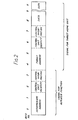
- a signal to be sent on the network 1 has the format as illustrated in Figure 2.
- the signal has three sections.
- One section defines the home unit which is to be used as an intermediate in a re-routing operation, this section consisting of two bytes for the address of the respective home unit acting as the intermediate, one byte indicating the identity of the central control unit (necessary when a number of networks, each with their own central control, are connected together) , and one byte for control information.
- Another section defines the home unit(s) which is or are the intended destination for the signal, this section consisting of two bytes for the address of the target home unit(s), one byte for the identity of the central control unit and one byte for control information.
- the remaining section consists of n bytes of data information to be supplied to the target home unit(s) to instruct whatever operation is appropriate.
- control unit 2 needing to communicate with HU 7
- the following table lists the necessary stages when the line attenuation and/or interference is such that the range of the signal output by control unit 2 is less than the distance between three home units, assuming (for the purpose of this simplified example) that they are all equi-spaced.
- Y represents the control information for any home unit acting as an intermediate
- W represents the control information for the target home unit HU 7
- Z represents the data information for the target home unit HU 7.
- main control unit 2 applies to the wiring 4 a signal R which has byte numbers 1 to 4 blank, byte numbers 4 and 5 containing identity H, byte number 6 containing identity A, byte number 7 containing W and byte numbers 8 to X containing Z.
- control unit 2 monitors wiring 4 for any response from HU 7, but none is forthcoming. Thereafter it proceeds to the second stage indicated in the table, and so on.
- each home unit has the ability to function either in normal mode or in repeater mode.
- the repeater capability of the home unit is achieved by the provision of programmed procedures held in memory devices; operation of these procedures is implemented when the home unit detects a repeater command in any received signal.
- the home unit uses a single set of access protocals both for its normal mode and for its repeater mode.
- the home unit consists of an interface connected to a control bus, which also functions as a system address bus and a system data bus.
- the control bus is connected to a processing block which incorporates a central processing unit, a clock and ROM and RAM storage which includes the normal mode procedures and the repeater mode procedure.
- the control bus is also connected to a power supply unit and to control units with interfaces to the user.
Abstract
Description
- The present invention relates to a data communications system, especi -".y but not solely to a mainsborne signalling system which mak,s use of the electrical supply wiring.
- A typical system, for utility telemetry, has a central controller located at a distribution substation and a large number of home units each sited at the premises of a consumer adjacent the electricity meter. Communication between the central controller and the home units is achieved by sending spread spectrum signals via the mains electricity circuit wiring. Clearly many sources of noise and attenuation (inter alia normal domestic equipment) are connected intermittently and randomly into the system, thereby producing unpredictable degrees of line attenuation and of interference with the system signals at any given time. Accordingly the range of a signal emitted from the central control (or from a home unit) tends to vary significantly, dependent on the time of day and on the time of day and on the season of the year.
- An object of the present invention is to provide a data communications system which is not subject to the disadvantages associated with the variability of signal range.
- The present invention provides a communications system having a main control unit and a plurality of stations, one or more of the stations having signal-repeater means, the system having means to selectively use the repeater means of one or more stations in the routing of a signal between the control unit and a station.
- The present invention also provides a communications system having a main control unit and a plurality of stations, one or more of the stations having signal-repeater means, the system having means to detect that a signal has not reached its intended station(s) and means to direct the signal to an intermediate station for subsequent routing to its intended station(s) .
- Thus, for example, when a system signal is unable to reach its destination station(s), it can be routed via one or more intermediate stations which act, in this circumstance, as a repeater.
- Preferably, the main control means incorporates means to modify the signal to address it to an intermediate station for subsequent routing to the intended station(s).
- Preferably the main control means has means to monitor for the launch of the signal from the intermediate station towards the intended station(s).
- Preferably the system utilizes a signal which includes a section identifying the target station(s) which is or are the intended destination of the signal, and a section identifying any intermediate station which is to act as a repeater in a re-routing operation.
- Preferably a station has means to process a received signal to locate and inspect any target identity and/or repeater identity contained within the received signal; the station may also have means to compare any identity of a received signal with that of the station identity and means to effect appropriate action.
- Preferably a station has a target identity which is for use when that station is the intended destination of a signal, and a repeater identity (different to the target identity) which is for use when that station is to operate on the signal as a repeater.
- In order that the invention may more readily be understood, a description is now given, by way of example only, reference being made to the accompanying drawings, in which:
- Figure 1 is a schematic diagram of part of a data communications system embodying the present invention; and
- Figure 2 is a schematic diagram of the format of a signal used in the system of Figure 1.
- The
mainsborne signalling network 1 illustrated in Figure 1 has amain control unit 2 located at a distribution substation; thiscontrol unit 2 can communicate with any of a number ofhome units 3 by means of signals sent along theelectrical mains wiring 4. Eachhome unit 3 is associated with a separate household and is located at the respective electricity meter such that it can provide information on the meter reading (and optionally on the condition of the meter) and other information whenever polled by thecontrol unit 2. In Figure 1, the home units are labelled "HU 1", "HU 2" and so on, in order to clarify distinction between individual units; some of the home units 3 (namelyHU 2,HU 4 and HU 6) have signal-repeater facilities, whose use will be described in greater detail below. Each of thecontrol unit 2 and of thehome units 3 has an address identity unique in thenetwork 1; for simplicity, the address identity forcontrol unit 2 is referred to as A, that forHU 1 as B, that forHU 2 as C and so on. - Consider the situation in which
control unit 2 requires to determine the electricity meter reading for the property at which HU 7 is located. Accordinglycontrol unit 2 applies, to themains wiring 4, a signal R targeted at HU7 and instructing it to send a return signal indicating the respective meter reading. Thereafter,control unit 2 monitors themains wiring 4 for any acknowledgement signals or return signals fromHU 7. If the line attenuation or interference on mains wiring circuit is substantial, it may reduce the range of any signal output fromcontrol unit 2 to such an extent that it would not reachHU 7. Thus, if after a predetermined time the control unit has not detected any such acknowledgement or return signal, it re-routes the signal R to an intermediate home unit which has a repeater facility, forexample HU 6. After sending out the re-routed signal R, it monitors thewiring 4 for any acknowledgement signal from HU6 or for launch of the signal fromHU 6 towardsHU 7; if, after a predetermined time,control unit 2 has not detected any such signal fromHU 6, it re-routes the signal R to a closer home unit with a signal-repeater facility, forexample HU 4. If the signal R reachesHU 4, then the latter cleans up and amplifies the signal R before launching it again ontomains wiring 4 towardsHU 7;HU 4 attempts to send the signal directly toHU 7, but if this fails it re-rautes it via an intermediate home unit with a signal-repeater facility, i.e. HU 6. Alternatively, HU 4 notes the range of the signal R already achieved (i.e. in this case fromcentral control unit 2 to HU 4) and plans the continued path toHU 7 accordingly. - A signal to be sent on the
network 1 has the format as illustrated in Figure 2. The signal has three sections. One section defines the home unit which is to be used as an intermediate in a re-routing operation, this section consisting of two bytes for the address of the respective home unit acting as the intermediate, one byte indicating the identity of the central control unit (necessary when a number of networks, each with their own central control, are connected together) , and one byte for control information. Another section defines the home unit(s) which is or are the intended destination for the signal, this section consisting of two bytes for the address of the target home unit(s), one byte for the identity of the central control unit and one byte for control information. The remaining section consists of n bytes of data information to be supplied to the target home unit(s) to instruct whatever operation is appropriate. - Returning to the situation of
control unit 2 needing to communicate withHU 7, the following table lists the necessary stages when the line attenuation and/or interference is such that the range of the signal output bycontrol unit 2 is less than the distance between three home units, assuming (for the purpose of this simplified example) that they are all equi-spaced.
- In this table, Y represents the control information for any home unit acting as an intermediate, W represents the control information for the target
home unit HU 7, and Z represents the data information for the targethome unit HU 7. Thus at the start of the transmission operation,main control unit 2 applies to the wiring 4 a signal R which hasbyte numbers 1 to 4 blank,byte numbers byte number 6 containing identity A,byte number 7 containing W andbyte numbers 8 to X containing Z. Oncecontrol unit 2 has applied this signal to wiring 4, the control unit monitors wiring 4 for any response fromHU 7, but none is forthcoming. Thereafter it proceeds to the second stage indicated in the table, and so on. - In one form of home unit for use in the
network 1, each home unit has the ability to function either in normal mode or in repeater mode. The repeater capability of the home unit is achieved by the provision of programmed procedures held in memory devices; operation of these procedures is implemented when the home unit detects a repeater command in any received signal. The home unit uses a single set of access protocals both for its normal mode and for its repeater mode. The home unit consists of an interface connected to a control bus, which also functions as a system address bus and a system data bus. The control bus is connected to a processing block which incorporates a central processing unit, a clock and ROM and RAM storage which includes the normal mode procedures and the repeater mode procedure. The control bus is also connected to a power supply unit and to control units with interfaces to the user.
Claims (12)
Applications Claiming Priority (2)
| Application Number | Priority Date | Filing Date | Title |
|---|---|---|---|
| GB858511758A GB8511758D0 (en) | 1985-05-09 | 1985-05-09 | Data communications systems |
| GB8511758 | 1985-05-09 |
Publications (3)
| Publication Number | Publication Date |
|---|---|
| EP0201253A2 true EP0201253A2 (en) | 1986-11-12 |
| EP0201253A3 EP0201253A3 (en) | 1988-06-08 |
| EP0201253B1 EP0201253B1 (en) | 1991-12-18 |
Family
ID=10578872
Family Applications (1)
| Application Number | Title | Priority Date | Filing Date |
|---|---|---|---|
| EP86303183A Expired - Lifetime EP0201253B1 (en) | 1985-05-09 | 1986-04-28 | Power line communications system |
Country Status (5)
| Country | Link |
|---|---|
| US (1) | US4937569A (en) |
| EP (1) | EP0201253B1 (en) |
| CA (1) | CA1252538A (en) |
| DE (1) | DE3682936D1 (en) |
| GB (1) | GB8511758D0 (en) |
Cited By (6)
| Publication number | Priority date | Publication date | Assignee | Title |
|---|---|---|---|---|
| EP0456395A2 (en) * | 1990-05-08 | 1991-11-13 | International Business Machines Corporation | System and method for monitoring electronic data processing equipment |
| EP0534710A1 (en) * | 1991-09-26 | 1993-03-31 | Vari-Lite, Inc. | Computer controlled lighting system with intelligent data distribution networks |
| WO1995001030A1 (en) * | 1993-06-25 | 1995-01-05 | Remote Metering Systems Ltd. | Mains signalling systems |
| WO1996005644A1 (en) * | 1994-08-10 | 1996-02-22 | Siemens Aktiengesellschaft | Telecontrol system with data transmission via the shielding of power transmission cables |
| GB2344674A (en) * | 1998-12-11 | 2000-06-14 | Pittway Corp | Message repeating |
| CN100462724C (en) * | 2003-12-16 | 2009-02-18 | 脉冲设备有限公司 | A power line communication system and an intelligent meter |
Families Citing this family (16)
| Publication number | Priority date | Publication date | Assignee | Title |
|---|---|---|---|---|
| JP2975724B2 (en) * | 1991-07-12 | 1999-11-10 | キヤノン株式会社 | Image communication device |
| US5835005A (en) * | 1994-07-13 | 1998-11-10 | Omron Corporation | Power-line data transmission method and system utilizing relay stations |
| GB9416688D0 (en) * | 1994-08-18 | 1994-10-12 | Remote Metering Systems Ltd | Mains signalling systems |
| US5818821A (en) | 1994-12-30 | 1998-10-06 | Intelogis, Inc. | Universal lan power line carrier repeater system and method |
| US5978371A (en) * | 1997-03-31 | 1999-11-02 | Abb Power T&D Company Inc. | Communications module base repeater |
| US20020120569A1 (en) * | 1997-10-16 | 2002-08-29 | Day Mark E. | System and method for communication between remote locations |
| US5986574A (en) * | 1997-10-16 | 1999-11-16 | Peco Energy Company | System and method for communication between remote locations |
| WO1999045510A2 (en) | 1998-03-03 | 1999-09-10 | Itron, Inc. | Method and system for reading intelligent utility meters |
| US9075136B1 (en) | 1998-03-04 | 2015-07-07 | Gtj Ventures, Llc | Vehicle operator and/or occupant information apparatus and method |
| US7236765B2 (en) * | 2003-07-24 | 2007-06-26 | Hunt Technologies, Inc. | Data communication over power lines |
| US7145438B2 (en) * | 2003-07-24 | 2006-12-05 | Hunt Technologies, Inc. | Endpoint event processing system |
| US7742393B2 (en) * | 2003-07-24 | 2010-06-22 | Hunt Technologies, Inc. | Locating endpoints in a power line communication system |
| US7180412B2 (en) | 2003-07-24 | 2007-02-20 | Hunt Technologies, Inc. | Power line communication system having time server |
| US8055461B2 (en) * | 2006-09-15 | 2011-11-08 | Itron, Inc. | Distributing metering responses for load balancing an AMR network |
| US8064826B2 (en) * | 2007-01-31 | 2011-11-22 | Broadcom Corporation | Intra-device RF bus and control thereof |
| US10546441B2 (en) | 2013-06-04 | 2020-01-28 | Raymond Anthony Joao | Control, monitoring, and/or security, apparatus and method for premises, vehicles, and/or articles |
Citations (4)
| Publication number | Priority date | Publication date | Assignee | Title |
|---|---|---|---|---|
| US3944723A (en) * | 1974-12-05 | 1976-03-16 | General Electric Company | Station for power line access data system |
| US3967264A (en) * | 1975-01-31 | 1976-06-29 | Westinghouse Electric Corporation | Distribution network power line communication system including addressable interrogation and response repeater |
| US4230989A (en) * | 1979-05-11 | 1980-10-28 | Engineered Systems, Inc. | Communications system with repeater stations |
| JPS5817750A (en) * | 1981-07-23 | 1983-02-02 | Sharp Corp | Data collection system |
Family Cites Families (6)
| Publication number | Priority date | Publication date | Assignee | Title |
|---|---|---|---|---|
| US3693155A (en) * | 1971-03-23 | 1972-09-19 | Nat Telecommunications System | Communication system |
| US4210901A (en) * | 1977-04-25 | 1980-07-01 | Westinghouse Electric Corp. | Signal repeater for a distribution network communication system |
| US4399531A (en) * | 1980-09-29 | 1983-08-16 | Rockwell International Corporation | Distributed digital data communications network |
| US4427968A (en) * | 1981-04-09 | 1984-01-24 | Westinghouse Electric Corp. | Distribution network communication system with flexible message routes |
| US4550397A (en) * | 1983-12-16 | 1985-10-29 | At&T Bell Laboratories | Alternate paths in a self-routing packet switching network |
| US4651318A (en) * | 1984-11-30 | 1987-03-17 | At&T Bell Laboratories | Self-routing packets with stage address identifying fields |
-
1985
- 1985-05-09 GB GB858511758A patent/GB8511758D0/en active Pending
-
1986
- 1986-04-28 EP EP86303183A patent/EP0201253B1/en not_active Expired - Lifetime
- 1986-04-28 DE DE8686303183T patent/DE3682936D1/en not_active Expired - Lifetime
- 1986-05-02 CA CA000508182A patent/CA1252538A/en not_active Expired
-
1988
- 1988-06-28 US US07/212,068 patent/US4937569A/en not_active Expired - Fee Related
Patent Citations (4)
| Publication number | Priority date | Publication date | Assignee | Title |
|---|---|---|---|---|
| US3944723A (en) * | 1974-12-05 | 1976-03-16 | General Electric Company | Station for power line access data system |
| US3967264A (en) * | 1975-01-31 | 1976-06-29 | Westinghouse Electric Corporation | Distribution network power line communication system including addressable interrogation and response repeater |
| US4230989A (en) * | 1979-05-11 | 1980-10-28 | Engineered Systems, Inc. | Communications system with repeater stations |
| JPS5817750A (en) * | 1981-07-23 | 1983-02-02 | Sharp Corp | Data collection system |
Non-Patent Citations (1)
| Title |
|---|
| PATENT ABSTRACTS OF JAPAN, vol. 7, no. 4 (E-171)(1239), 20th April 1983; & JP-A-58 017 750 (SHARP K.K.) 02-02-1983 * |
Cited By (9)
| Publication number | Priority date | Publication date | Assignee | Title |
|---|---|---|---|---|
| EP0456395A2 (en) * | 1990-05-08 | 1991-11-13 | International Business Machines Corporation | System and method for monitoring electronic data processing equipment |
| EP0456395A3 (en) * | 1990-05-08 | 1993-09-01 | International Business Machines Corporation | System and method for monitoring electronic data processing equipment |
| EP0534710A1 (en) * | 1991-09-26 | 1993-03-31 | Vari-Lite, Inc. | Computer controlled lighting system with intelligent data distribution networks |
| WO1995001030A1 (en) * | 1993-06-25 | 1995-01-05 | Remote Metering Systems Ltd. | Mains signalling systems |
| WO1996005644A1 (en) * | 1994-08-10 | 1996-02-22 | Siemens Aktiengesellschaft | Telecontrol system with data transmission via the shielding of power transmission cables |
| GB2344674A (en) * | 1998-12-11 | 2000-06-14 | Pittway Corp | Message repeating |
| US6252501B1 (en) | 1998-12-11 | 2001-06-26 | Pittway Corporation | Message repeating apparatus and method |
| GB2344674B (en) * | 1998-12-11 | 2003-07-09 | Pittway Corp | Message repeating apparatus and method |
| CN100462724C (en) * | 2003-12-16 | 2009-02-18 | 脉冲设备有限公司 | A power line communication system and an intelligent meter |
Also Published As
| Publication number | Publication date |
|---|---|
| EP0201253B1 (en) | 1991-12-18 |
| DE3682936D1 (en) | 1992-01-30 |
| GB8511758D0 (en) | 1985-06-19 |
| EP0201253A3 (en) | 1988-06-08 |
| US4937569A (en) | 1990-06-26 |
| CA1252538A (en) | 1989-04-11 |
Similar Documents
| Publication | Publication Date | Title |
|---|---|---|
| EP0201253A2 (en) | Power line communications system | |
| US4955018A (en) | Protocol for network having plurality of intelligent cells | |
| US4885564A (en) | Power line carrier communication system for monitoring refrigerated containers | |
| US4918690A (en) | Network and intelligent cell for providing sensing, bidirectional communications and control | |
| US4969146A (en) | Protocol for network having a plurality of intelligent cells | |
| US4941143A (en) | Protocol for network having a plurality of intelligent cells | |
| US4947484A (en) | Protocol for network having a plurality of intelligent cells | |
| US5034882A (en) | Multiprocessor intelligent cell for a network which provides sensing, bidirectional communications and control | |
| US4953194A (en) | Automated documentation system for a communications network | |
| EP0062870A1 (en) | Distribution network communication system | |
| AU7040094A (en) | Mains signalling systems | |
| JPH0616624B2 (en) | Circuit device for voltage supply | |
| CA1177931A (en) | Two-way optical data communication system | |
| EP1251721A1 (en) | Urban remote surveillance system for street lamps | |
| EP0071367B1 (en) | Self-sequencing data bus allocation system | |
| CN101473700B (en) | Method and device for transmitting information over a complex network | |
| CA1309186C (en) | Input/output section for an intelligent cell which provides sensing, bidirectional communications and control | |
| US5973610A (en) | System for automated selection of a communications unit for refrigerating containers | |
| JP2000350271A (en) | Power-line carrier communication system | |
| CN101904106A (en) | Method for transmitting data records | |
| JPH0122782B2 (en) | ||
| AU621581B2 (en) | Protocol for network having a plurality of intelligent cells | |
| FI970541A (en) | Remote control system where data transmission takes place via the sheath of an energy transmission cable | |
| JPS5857829A (en) | Power line data transmitting system | |
| ATE6975T1 (en) | REMOTE CONTROL DEVICE WITH OUTPUT OF RECEIVED MESSAGES AND STATUS MESSAGES DEPENDING ON THE OPERATING STATUS OF THE STATIONS. |
Legal Events
| Date | Code | Title | Description |
|---|---|---|---|
| PUAI | Public reference made under article 153(3) epc to a published international application that has entered the european phase |
Free format text: ORIGINAL CODE: 0009012 |
|
| AK | Designated contracting states |
Kind code of ref document: A2 Designated state(s): DE FR GB IT NL SE |
|
| PUAL | Search report despatched |
Free format text: ORIGINAL CODE: 0009013 |
|
| AK | Designated contracting states |
Kind code of ref document: A3 Designated state(s): DE FR GB IT NL SE |
|
| 17P | Request for examination filed |
Effective date: 19880916 |
|
| RAP1 | Party data changed (applicant data changed or rights of an application transferred) |
Owner name: THORN EMI PATENTS LIMITED |
|
| 17Q | First examination report despatched |
Effective date: 19901029 |
|
| GRAA | (expected) grant |
Free format text: ORIGINAL CODE: 0009210 |
|
| AK | Designated contracting states |
Kind code of ref document: B1 Designated state(s): DE FR GB IT NL SE |
|
| ITF | It: translation for a ep patent filed |
Owner name: FUMERO BREVETTI S.N.C. |
|
| REF | Corresponds to: |
Ref document number: 3682936 Country of ref document: DE Date of ref document: 19920130 |
|
| ET | Fr: translation filed | ||
| PLBE | No opposition filed within time limit |
Free format text: ORIGINAL CODE: 0009261 |
|
| STAA | Information on the status of an ep patent application or granted ep patent |
Free format text: STATUS: NO OPPOSITION FILED WITHIN TIME LIMIT |
|
| 26N | No opposition filed | ||
| PGFP | Annual fee paid to national office [announced via postgrant information from national office to epo] |
Ref country code: SE Payment date: 19940210 Year of fee payment: 9 |
|
| PGFP | Annual fee paid to national office [announced via postgrant information from national office to epo] |
Ref country code: FR Payment date: 19940224 Year of fee payment: 9 |
|
| PGFP | Annual fee paid to national office [announced via postgrant information from national office to epo] |
Ref country code: NL Payment date: 19940430 Year of fee payment: 9 |
|
| PGFP | Annual fee paid to national office [announced via postgrant information from national office to epo] |
Ref country code: DE Payment date: 19940622 Year of fee payment: 9 |
|
| EAL | Se: european patent in force in sweden |
Ref document number: 86303183.7 |
|
| PG25 | Lapsed in a contracting state [announced via postgrant information from national office to epo] |
Ref country code: SE Effective date: 19950429 |
|
| PG25 | Lapsed in a contracting state [announced via postgrant information from national office to epo] |
Ref country code: NL Effective date: 19951101 |
|
| PG25 | Lapsed in a contracting state [announced via postgrant information from national office to epo] |
Ref country code: FR Effective date: 19951229 |
|
| NLV4 | Nl: lapsed or anulled due to non-payment of the annual fee |
Effective date: 19951101 |
|
| PG25 | Lapsed in a contracting state [announced via postgrant information from national office to epo] |
Ref country code: DE Effective date: 19960103 |
|
| EUG | Se: european patent has lapsed |
Ref document number: 86303183.7 |
|
| REG | Reference to a national code |
Ref country code: FR Ref legal event code: ST |
|
| REG | Reference to a national code |
Ref country code: GB Ref legal event code: 732E |
|
| REG | Reference to a national code |
Ref country code: GB Ref legal event code: 732E |
|
| REG | Reference to a national code |
Ref country code: GB Ref legal event code: 732E |
|
| REG | Reference to a national code |
Ref country code: GB Ref legal event code: IF02 |
|
| PGFP | Annual fee paid to national office [announced via postgrant information from national office to epo] |
Ref country code: GB Payment date: 20031027 Year of fee payment: 18 |
|
| PG25 | Lapsed in a contracting state [announced via postgrant information from national office to epo] |
Ref country code: GB Free format text: LAPSE BECAUSE OF NON-PAYMENT OF DUE FEES Effective date: 20040428 |
|
| GBPC | Gb: european patent ceased through non-payment of renewal fee |
Effective date: 20040428 |
|
| PG25 | Lapsed in a contracting state [announced via postgrant information from national office to epo] |
Ref country code: IT Free format text: LAPSE BECAUSE OF NON-PAYMENT OF DUE FEES;WARNING: LAPSES OF ITALIAN PATENTS WITH EFFECTIVE DATE BEFORE 2007 MAY HAVE OCCURRED AT ANY TIME BEFORE 2007. THE CORRECT EFFECTIVE DATE MAY BE DIFFERENT FROM THE ONE RECORDED. Effective date: 20050428 |