EP0202723A2 - Remote reading system of a counter-position - Google Patents
Remote reading system of a counter-position Download PDFInfo
- Publication number
- EP0202723A2 EP0202723A2 EP86200900A EP86200900A EP0202723A2 EP 0202723 A2 EP0202723 A2 EP 0202723A2 EP 86200900 A EP86200900 A EP 86200900A EP 86200900 A EP86200900 A EP 86200900A EP 0202723 A2 EP0202723 A2 EP 0202723A2
- Authority
- EP
- European Patent Office
- Prior art keywords
- plate
- transmission
- counter
- wall
- hole
- Prior art date
- Legal status (The legal status is an assumption and is not a legal conclusion. Google has not performed a legal analysis and makes no representation as to the accuracy of the status listed.)
- Withdrawn
Links
Images
Classifications
-
- G—PHYSICS
- G06—COMPUTING; CALCULATING OR COUNTING
- G06M—COUNTING MECHANISMS; COUNTING OF OBJECTS NOT OTHERWISE PROVIDED FOR
- G06M3/00—Counters with additional facilities
- G06M3/06—Counters with additional facilities for printing or separately displaying result of count
-
- G—PHYSICS
- G01—MEASURING; TESTING
- G01F—MEASURING VOLUME, VOLUME FLOW, MASS FLOW OR LIQUID LEVEL; METERING BY VOLUME
- G01F15/00—Details of, or accessories for, apparatus of groups G01F1/00 - G01F13/00 insofar as such details or appliances are not adapted to particular types of such apparatus
- G01F15/06—Indicating or recording devices
- G01F15/061—Indicating or recording devices for remote indication
- G01F15/063—Indicating or recording devices for remote indication using electrical means
Definitions
- the present invention relates to the remote reading of the index of a totalizing meter with contact pads and relates to an improvement of the transmission system of this index, applicable to all kinds of fluids, such as water, gas, fuel oil or electricity.
- a microswitch detects the presence of this plate and warns of it a suitable computer, which sends a power wave train through the transformer coil with the coil of the transmission plate, the latter then supplying power to all the electronics placed in the meter.
- the demodulation in the counter provides the necessary signals to the electronics for the demultiplexing and the serial reading of switched pads and the number of the counter.
- the serial output is made via the second coil of the transmission plate forming a weak signal transformer with the second coil of the reading gun, whose signal is amplified to provide the computer with the index and the number of the counter, data which at this point are still coded with a verification system.
- the computer then decodes this data and displays the result on its LCD screen.
- a keyboard allows the easy manipulation of the data, which can at the end of the day be transferred without problem to the main management computer of the distributing company.
- the object of the invention is to provide an improvement to this known reading system by a characteristic conformation of the meter transmission plate.
- an inductive transmission plate is characterized in that it consists of a base comprising the transmission coil (s) and provided on its rear face with a single locating pin, through which the connecting cable projects. to the counter and intended to be inserted into a wall.
- the invention also relates to the system for fixing such a transmission plate. It consists of drilling a hole in the support wall corresponding to the diameter of the locating pin, passing the connecting cable through this hole, coating the rear face of the plate and said pin with a hardening adhesive agent. apply the plate against the wall with the dowel in the hole and hold the plate in place to allow the setting of the adhesive agent.
- An inductive transmission plate for reading the index of a totalizer with contact pads, such as that described in the patent application filed jointly by the applicant, consists of a base 1 containing two coils of transmission, a coil 2 intended to supply power to all the electronics of the meter and a coil 3 for the serial output, and carrying on its rear face a locating pin 4.
- Such a plate is intended to be affixed to a wall, so as to be easily accessible to the operator. It is easy to see that it can be affixed, for example, to the front door of a building. Thus, such a plate can still advantageously be provided on its front face with a ringing switch 6 and a label holder 7.
- the fixing has the advantage of being completely tight with respect to gas and humidity and of offering no cavity to shelter parasites, without counting the ease of installation thanks to a single and unique hole, for example in the front door of a building.
Abstract
Description
La présente invention concerne la lecture à distance de l'index d'un compteur totalisateur à plots de contact et est relative à un perfectionnement du système de transmission de cet index, applicable à tout genre de fluides, tels que eau, gaz, mazout ou électricité.The present invention relates to the remote reading of the index of a totalizing meter with contact pads and relates to an improvement of the transmission system of this index, applicable to all kinds of fluids, such as water, gas, fuel oil or electricity.
Il est connu que dans le système de lecture à distance de l'index d'un compteur, lorsque l'opérateur pose un pistolet de lecture sur une plaque de transmission du compteur, un micros- witch détecte la présence de cette plaque et en avertit un ordinateur approprié, qui envoie un train d'ondes de puissance à travers la bobine formant transformateur avec la bobine de la plaque de transmission, celle-ci fournissant alors la puissance à toute l'électronique placée dans le compteur.It is known that in the remote reading system of the index of a counter, when the operator places a reading gun on a transmission plate of the meter, a microswitch detects the presence of this plate and warns of it a suitable computer, which sends a power wave train through the transformer coil with the coil of the transmission plate, the latter then supplying power to all the electronics placed in the meter.
Le train d'ondes étant modulé, la démodulation dans le compteur fournit les signaux nécessaires à l'électronique pour le démultiplexage et la lecture sérielle de plots commutés et du numéro du compteur.The wave train being modulated, the demodulation in the counter provides the necessary signals to the electronics for the demultiplexing and the serial reading of switched pads and the number of the counter.
La sortie sérielle se fait via la seconde bobine de la plaque de transmission formant transformateur de signaux faibles avec la seconde bobine du pistolet de lecture, dont le signal est amplifié pour fournir à l'ordinateur l'index et le numéro du compteur, données qui à ce stade sont encore codées avec un système de vérification. Ensuite, l'ordinateur décode ces données et affiche le résultat sur son écran LCD.The serial output is made via the second coil of the transmission plate forming a weak signal transformer with the second coil of the reading gun, whose signal is amplified to provide the computer with the index and the number of the counter, data which at this point are still coded with a verification system. The computer then decodes this data and displays the result on its LCD screen.
Un clavier permet la manipulation aisée des données, qui peuvent à la fin de la journée être transférées sans problème vers l'ordinateur principal de gestion de la société distributrice.A keyboard allows the easy manipulation of the data, which can at the end of the day be transferred without problem to the main management computer of the distributing company.
L'objet de l'invention est d'apporter un perfectionnement à ce système de lecture connu par une conformation caractéristique de la plaque de transmission du compteur.The object of the invention is to provide an improvement to this known reading system by a characteristic conformation of the meter transmission plate.
Suivant l'invention une plaque de transmission inductive est caractérisée en ce qu'elle consiste en un socle comportant la ou les bobines de transmission et pourvu sur sa face arrière d'une unique cheville de localisation, à travers laquelle fait saillie le câble de liaison au compteur et destinée à être insérée dans une paroi.According to the invention, an inductive transmission plate is characterized in that it consists of a base comprising the transmission coil (s) and provided on its rear face with a single locating pin, through which the connecting cable projects. to the counter and intended to be inserted into a wall.
L'invention concerne également le système de fixation d'une telle plaque de transmission. Il consiste à forer dans la paroi de support un trou correspondant au diamètre de la cheville de localisation, à faire passer le câble de liaison à travers ce trou, à enduire la face arrière de la plaque et ladite cheville d'un agent collant durcissable à appliquer la plaque contre la paroi avec la cheville dans le trou et à maintenir la plaque en place pour permettre la prise de l'agent collant.The invention also relates to the system for fixing such a transmission plate. It consists of drilling a hole in the support wall corresponding to the diameter of the locating pin, passing the connecting cable through this hole, coating the rear face of the plate and said pin with a hardening adhesive agent. apply the plate against the wall with the dowel in the hole and hold the plate in place to allow the setting of the adhesive agent.
Pour mieux faire comprendre l'invention celle-ci est décrite maintenant sur la base du dessin annexé, à titre d'exemple uniquement, montrant en
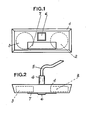
- Figure 1 une vue de face d'une plaque de transmission suivant l'invention, et
- Figure 2 une vue en plan de la plaque de la figure 1.
- Figure 1 a front view of a transmission plate according to the invention, and
- Figure 2 a plan view of the plate of Figure 1.
Une plaque de transmission inductive suivant l'invention pour la lecture de l'index d'un compteur totalisateur à plots de contact, tel que celui décrit dans la demande de brevet déposée conjointement par la demanderesse, consiste en un socle 1 renfermant deux bobines de transmission, une bobine 2 destinée à fournir la puissance à toute l'électronique du compteur et une bobine 3 pour la sortie sérielle, et portant sur sa face arrière une cheville de localisation 4.An inductive transmission plate according to the invention for reading the index of a totalizer with contact pads, such as that described in the patent application filed jointly by the applicant, consists of a
Une telle plaque est destinée à être apposée sur une paroi, de manière à être facilement accessible pour l'opérateur. On conçoit aisément qu'elle puisse être apposée par exemple sur la porte d'entrée d'un immeuble. C'est ainsi qu'une telle plaque peut encore être avantageusement pourvue sur sa face avant d'un commutateur de sonnerie 6 et d'un porte-étiquette 7.Such a plate is intended to be affixed to a wall, so as to be easily accessible to the operator. It is easy to see that it can be affixed, for example, to the front door of a building. Thus, such a plate can still advantageously be provided on its front face with a
Le but de l'invention en conformant la plaque de transmission de cette manière est de simplifier à l'extrême sa fixation. En effet, le système de fixation consiste à :
- -forer un seul et unique trou, du diamètre de la cheville de localisation, dans la paroi de support ;
- -passer le câble de transmission dans le trou ;
- -enduire la face arrière de la plaque et la cheville de localisation d'un agent collant durcissable ;
- -appliquer la plaque contre la paroi avec la cheville dans le trou ;
- -maintenir la plaque en place en pinçant le câble de l'autre côté de la paroi pour permettre la prise de l'agent collant.
- -bore a single hole, the diameter of the locating pin, in the support wall;
- - pass the transmission cable through the hole;
- coat the rear face of the plate and the locating pin with a curable adhesive agent;
- -apply the plate against the wall with the dowel in the hole;
- -maintain the plate in place by pinching the cable on the other side of the wall to allow the setting of the adhesive agent.
Grâce à un tel système la fixation présente l'avantage d'être complètement étanche par rapport au gaz et à l'humidité et de n'offrir aucune cavité pour abriter des parasites, sans compter la facilité d'installation grâce à un seul et unique trou, par exemple dans la porte d'entrée d'un immeuble.Thanks to such a system, the fixing has the advantage of being completely tight with respect to gas and humidity and of offering no cavity to shelter parasites, without counting the ease of installation thanks to a single and unique hole, for example in the front door of a building.
Claims (3)
Applications Claiming Priority (2)
| Application Number | Priority Date | Filing Date | Title |
|---|---|---|---|
| BE6/48094A BE902501A (en) | 1985-05-24 | 1985-05-24 | Inductive coupling for remote reading totaliser - uses single locating pin and adhesive for mounting and passing cable |
| BE6048094 | 1985-05-24 |
Publications (2)
| Publication Number | Publication Date |
|---|---|
| EP0202723A2 true EP0202723A2 (en) | 1986-11-26 |
| EP0202723A3 EP0202723A3 (en) | 1989-05-24 |
Family
ID=3874972
Family Applications (1)
| Application Number | Title | Priority Date | Filing Date |
|---|---|---|---|
| EP86200900A Withdrawn EP0202723A3 (en) | 1985-05-24 | 1986-05-23 | Remote reading system of a counter-position |
Country Status (2)
| Country | Link |
|---|---|
| EP (1) | EP0202723A3 (en) |
| BE (1) | BE902501A (en) |
Citations (3)
| Publication number | Priority date | Publication date | Assignee | Title |
|---|---|---|---|---|
| DE1931399A1 (en) * | 1968-06-21 | 1970-01-02 | Michelin & Cie | Device for the transmission of information between mutually moving elements |
| GB2074816A (en) * | 1980-02-01 | 1981-11-04 | Techwise International Ltd | A door bell or like device arranged to emit a warning sound upon activation of a remotely situated switch |
| US4463354A (en) * | 1981-12-09 | 1984-07-31 | Sears Lawrence M | Apparatus for communicating utility usage related information from a utility usage location to a portable utility usage registering device |
-
1985
- 1985-05-24 BE BE6/48094A patent/BE902501A/en unknown
-
1986
- 1986-05-23 EP EP86200900A patent/EP0202723A3/en not_active Withdrawn
Patent Citations (3)
| Publication number | Priority date | Publication date | Assignee | Title |
|---|---|---|---|---|
| DE1931399A1 (en) * | 1968-06-21 | 1970-01-02 | Michelin & Cie | Device for the transmission of information between mutually moving elements |
| GB2074816A (en) * | 1980-02-01 | 1981-11-04 | Techwise International Ltd | A door bell or like device arranged to emit a warning sound upon activation of a remotely situated switch |
| US4463354A (en) * | 1981-12-09 | 1984-07-31 | Sears Lawrence M | Apparatus for communicating utility usage related information from a utility usage location to a portable utility usage registering device |
Also Published As
| Publication number | Publication date |
|---|---|
| EP0202723A3 (en) | 1989-05-24 |
| BE902501A (en) | 1985-09-16 |
Similar Documents
| Publication | Publication Date | Title |
|---|---|---|
| US5214587A (en) | Device for monitoring utility usage | |
| AU4209399A (en) | Portable information display device with ergonomic bezel | |
| ATE356370T1 (en) | BISTABLE REFLECTION DISPLAY DEVICE WITH CONVERTED CONTRAST | |
| AU5814398A (en) | Optical profilometer combined with stylus probe measurement device | |
| WO1999003005A3 (en) | Optical computational system | |
| AU5804296A (en) | Transflective displays with reflective polarizing transflector | |
| JP6242499B2 (en) | Wristwatch with a fluorescent time display dial | |
| WO1997044707A3 (en) | Liquid crystal display device with integrated solar power source and antenna | |
| ATE513272T1 (en) | HIGH FREQUENCY IDENTIFICATION OF A CONNECTOR USING A PANEL OR SIMILAR STRUCTURE | |
| AU4724397A (en) | Surface light source and liquid crystal display, portable telephone and information terminal employing the surface light source | |
| DE69321114D1 (en) | Read head with two functions for reflection measuring device | |
| DE59915078D1 (en) | ||
| WO2002044653A8 (en) | Integrated optic gyroscope and method of fabrication | |
| WO2003088286A3 (en) | Electro-optical circuitry having integrated connector and methods for the production thereof | |
| EP0202723A2 (en) | Remote reading system of a counter-position | |
| HK1012081A1 (en) | Watch with a display device associated with an optical magnifying device | |
| WO2005060522A3 (en) | Low-loss compact reflective turns in optical waveguides | |
| GB2462006A (en) | Device for optically reading a utility meter, with pass-through communication | |
| GB2280544B (en) | Providing optical coupling with single crystal substrate mounted electro-optic transducers | |
| WO2002050592A3 (en) | Photonic and electronic components on a shared substrate with through substrate communication | |
| SE9902552D0 (en) | Optical coupling | |
| WO2001098815A3 (en) | Display device | |
| WO2002048989A3 (en) | Display housing | |
| FR2803043B1 (en) | DEVICE FOR MEASURING AN ELECTROMAGNETIC FIELD WITH ANY POLARIZATION | |
| WO2005043084A3 (en) | A tap- resistant system with an optical device |
Legal Events
| Date | Code | Title | Description |
|---|---|---|---|
| PUAI | Public reference made under article 153(3) epc to a published international application that has entered the european phase |
Free format text: ORIGINAL CODE: 0009012 |
|
| AK | Designated contracting states |
Kind code of ref document: A2 Designated state(s): AT CH DE FR GB IT LI LU NL SE |
|
| PUAL | Search report despatched |
Free format text: ORIGINAL CODE: 0009013 |
|
| AK | Designated contracting states |
Kind code of ref document: A3 Designated state(s): AT CH DE FR GB IT LI LU NL SE |
|
| STAA | Information on the status of an ep patent application or granted ep patent |
Free format text: STATUS: THE APPLICATION IS DEEMED TO BE WITHDRAWN |
|
| 18D | Application deemed to be withdrawn |
Effective date: 19891127 |
|
| RIN1 | Information on inventor provided before grant (corrected) |
Inventor name: LENFANT, THEO |