EP0213577B1 - Apparatus providing data backup upon power failure in a micro-computer controlled television receiver - Google Patents
Apparatus providing data backup upon power failure in a micro-computer controlled television receiver Download PDFInfo
- Publication number
- EP0213577B1 EP0213577B1 EP86111668A EP86111668A EP0213577B1 EP 0213577 B1 EP0213577 B1 EP 0213577B1 EP 86111668 A EP86111668 A EP 86111668A EP 86111668 A EP86111668 A EP 86111668A EP 0213577 B1 EP0213577 B1 EP 0213577B1
- Authority
- EP
- European Patent Office
- Prior art keywords
- data
- micro
- computer
- ram
- voltage
- Prior art date
- Legal status (The legal status is an assumption and is not a legal conclusion. Google has not performed a legal analysis and makes no representation as to the accuracy of the status listed.)
- Expired - Lifetime
Links
Images


Classifications
-
- G—PHYSICS
- G06—COMPUTING; CALCULATING OR COUNTING
- G06F—ELECTRIC DIGITAL DATA PROCESSING
- G06F11/00—Error detection; Error correction; Monitoring
- G06F11/07—Responding to the occurrence of a fault, e.g. fault tolerance
- G06F11/0703—Error or fault processing not based on redundancy, i.e. by taking additional measures to deal with the error or fault not making use of redundancy in operation, in hardware, or in data representation
- G06F11/0751—Error or fault detection not based on redundancy
- G06F11/0754—Error or fault detection not based on redundancy by exceeding limits
-
- G—PHYSICS
- G06—COMPUTING; CALCULATING OR COUNTING
- G06F—ELECTRIC DIGITAL DATA PROCESSING
- G06F1/00—Details not covered by groups G06F3/00 - G06F13/00 and G06F21/00
- G06F1/26—Power supply means, e.g. regulation thereof
- G06F1/30—Means for acting in the event of power-supply failure or interruption, e.g. power-supply fluctuations
-
- G—PHYSICS
- G06—COMPUTING; CALCULATING OR COUNTING
- G06F—ELECTRIC DIGITAL DATA PROCESSING
- G06F11/00—Error detection; Error correction; Monitoring
- G06F11/07—Responding to the occurrence of a fault, e.g. fault tolerance
- G06F11/14—Error detection or correction of the data by redundancy in operation
- G06F11/1402—Saving, restoring, recovering or retrying
- G06F11/1415—Saving, restoring, recovering or retrying at system level
- G06F11/1441—Resetting or repowering
-
- G—PHYSICS
- G11—INFORMATION STORAGE
- G11C—STATIC STORES
- G11C14/00—Digital stores characterised by arrangements of cells having volatile and non-volatile storage properties for back-up when the power is down
-
- G—PHYSICS
- G11—INFORMATION STORAGE
- G11C—STATIC STORES
- G11C5/00—Details of stores covered by group G11C11/00
- G11C5/14—Power supply arrangements, e.g. power down, chip selection or deselection, layout of wirings or power grids, or multiple supply levels
- G11C5/141—Battery and back-up supplies
-
- G—PHYSICS
- G11—INFORMATION STORAGE
- G11C—STATIC STORES
- G11C7/00—Arrangements for writing information into, or reading information out from, a digital store
-
- H—ELECTRICITY
- H03—ELECTRONIC CIRCUITRY
- H03J—TUNING RESONANT CIRCUITS; SELECTING RESONANT CIRCUITS
- H03J1/00—Details of adjusting, driving, indicating, or mechanical control arrangements for resonant circuits in general
- H03J1/0008—Details of adjusting, driving, indicating, or mechanical control arrangements for resonant circuits in general using a central processing unit, e.g. a microprocessor
Definitions
- This invention relates generally to an apparatus for accommodating power failures in a micro-computer controlled electronic system, especially in a television receiver.
- Modern television receivers comprise an apparatus of the above mentioned type, said apparatus comprising:
- such an apparatus additionally comprises a non-volatile memory into which data are transferred from said RAM in case of a power failure.
- a non-volatile memory When transferring the data, it makes no sense to transfer time display data.
- nonvolatile memories typically use some sort of magnetic elements, such as bubble memory elements, which can generally only be accessed about 100,00 times in their lifetime. This is perfectly adequate to accommodate the number of times a television receiver is turned on and off, be it manually or by power failures, during its lifetime, which on the average is about 7 years, however, is not enough to stand this lifetime in case of updating time display data. Therefore, the power source is typically backed-up by a special, large value condenser or a capacitor bank to prevent the time display data in the RAM of the micro-computer from being erased when power failure occurs.
- EP-A-0 043 462 An apparatus similar to the one described above, however, with no time display feature, is described in EP-A-0 043 462.
- the terminal voltage of a capacitor which is provided for data holding purposes, is detected, when a main power source is connected, to judge whether data have extinguished from a memory. If this is the case, new data have to be input via a keyboard.
- Power failures can last for an appreciable period of time, such as they are caused by a storm or the like, however, in most cases the power failures are essentially instantaneous and are terminated within a second or less.
- Such power failures or brief outages may be caused by generator switch overs or network changes within the power grid, and brief power outages can also be caused in the home by rapid increases in load, such as when the motor of a refrigerator or air conditioner unit is suddenly switched on.
- the apparatus of the present invention is able to save the time display information in case of the above mentioned typical brief power failures.
- This function is performed due to a RAM which has a data holding voltage which is lower than the operating voltage of the micro-computer, and due to a standby power source having a voltage-time-relation insuring that the voltage supplied in case of a power failure remains above the just mentioned data holding voltage during the time period of a typical brief voltage failure.
- the apparatus of the present invention does not check this voltage, but it checks whether a checking condition is fulfilled for predetermined stored checking data.
- these checking data are the time display data themselves. In these data, the tens minute digit always has to have a value below "6" and the tens hour digit has to have a value below "2" in case that the voltage as supplied by the standby power source did not fall below the data holding voltage.
- Fig. 1 schematically represents a portion of a micro-computer controlled television receiver and, more particularly, reference numerals 1 through 7 designate those circuits that form the main receiving system of a television receiver.
- the television signal is received at the antenna AN and is supplied to a tuner circuit 1, and the video intermediate frequency signal (IF) from tuner 1 is fed through an intermediate frequency (IF) amplifier 2 to a video output circuit 3, from which the three primary color signals are derived and fed to a color cathode ray tube 4 for display.
- the intermediate frequency signal from the IF amplifier 2 is also supplied to an audio output circuit 5, which derives the audio signal therefrom and feeds it to a loudspeaker 6.
- Tuning is typically achieved by means of a channel selection control circuit 7 that provides a tuning signal to tuner circuit 1 so that the appropriate channel selection is carried out.
- micro-computer 10 typically found in this type of digital television receiver carries out the control operations, such as channel selection and the like, and one form that micro-computer 10 may take is that of a one-chip micro-computer with four-bit data processing.
- micro-computer 10 includes a central processing unit 11 (CPU), a read only memory 12 (ROM), in which the various kinds of control programs are written, and a random access memory 13 (RAM) used as a work area and a data area.
- CPU central processing unit 11
- ROM read only memory
- RAM random access memory 13
- a plurality of input ports 14 and output ports 15 typically found in micro-computers are also provided.
- these circuit elements 12 through 15 making up micro-computer 10 are all connected to the central processing unit 11 by a common bus 16.
- television receivers typically include a number of function selecting and operating keys, and such keys are represented at 21A through 21N and are connected to micro-computer 10 through input port 14.
- tuning control to change the station by increasing or decreasing the channel number can be provided at keys 21A, and such channel selection data would be stored in random access memory 13 and supplied through output port 15 to control circuit 7, which provides a control voltage Vc that varies to tune the channel in tuner 1.
- other control signals are derived in response to operation of keys 21B through 21N, with the appropriate control signals being supplied through the input ports 14 and output ports 15 to video output circuit 3 and audio output circuit 5 for changing volume, picture contrast, hue, color, and the like.
- a main power source circuit 32 is provided and one of keys 21A through 21N would be the main power key, so that when the power key is depressed a relay 22 will be driven by a signal produced at output port 15 and the relay contacts 22S will be closed.
- a standard utility AC voltage from power source plug 31 is applied through relay contacts 22S to a main power source circuit 32 that produces a predetermined DC voltage used to operate the circuits of the television receiver.
- the DC voltage generated by main power source circuit 32 would be supplied to all of the circuits 1 through 7 as the respective operating voltages thereof.
- a standby power source circuit 33 is connected to the line voltage through plug 31 and provides a DC voltage V5 that may be, for example, 5 volts.
- This DC voltage V5 is always supplied to micro-computer 10 as the operation voltage thereof, even when the television has been turned off, in order to keep the necessary data in RAM 13.
- Reset circuit 34 receives DC voltage V5 as the input voltage thereto and if DC voltage V5 drops to a voltage less than the operational voltage of micro-computer 10, which may be, for example, 4 volts, reset circuit 34 will detect this voltage drop and supply an output signal to central processing unit 11 as a reset signal therefor. Accordingly, central processing unit 11 is kept reset by reset circuit 34 during a time period in which the AC line voltage drops to an unacceptable limit.
- Fig. 2A the AC line voltage is arbitrarily shown as 100 volts and a brief period is shown during which the line voltage drops to zero volts before resuming the desired voltage level of 100 volts.
- Fig. 2B then represents the output from standby power source circuit 33 as DC voltage V5 in which it is seen that in correspondence with the line voltage, the DC voltage V5 also drops below the operational voltage of 5 volts. Once the AC line voltage recovers, the DC voltage V5 then will resume its 5 volt operational level, and this period of time below the operational level is denoted as time period Tr.
- a waveform shaping circuit 35 has its input connected to standby power source circuit 33 and generates a reference clock signal suitable for the clock data.
- standby power source circuit 33 provides an AC signal that has the line voltage frequency (50 or 60 cycles) but with a substantially reduced peak to peak voltage.
- waveform shaping circuit 35 squares the alternating current signal to a square wave signal that is supplied through input port 14 as the reference clock for counting the current time.
- This reference clock is counted by central processing unit 11 to form a signal indicating the current hour and minute, which is then supplied through output port 15 to a digital time display 23 that displays the appropriate numerals.
- an elapsed time count could be displayed and a so-called sleep timer could be implemented utilizing these same elements.
- a nonvolatile random access memory 24 is connected to micro-computer 10 through input ports 14 and output ports 15 such that when the power source circuit 32 is switched off by operation of one of the keys 21N, the channel data, volume data, and the like that are stored in random access memory 13 will be automatically transferred to nonvolatile random access memory 24 and stored therein even though the relay contacts 22S are open. This is the backup in case the power outage occurs, or the plug 31 is pulled out. In any event, however, according to the present invention the time display data is not transferred to nonvolatile memory 24.
- Fig. 3 is a pictorial representation of the data stored within random access memory 13 being transferred to the nonvolatile random access memory 24 and back again. Because the standby power source circuit 33 is connected to the main power line through plug 31 at a point electrically before the relay contacts 22S even though the television receiver and power source circuit 32 are switched off, micro-computer 10 will remain powered so that the data stored in the RAM 13 is not erased. Nevertheless, in the event that a power failure occurs or plug 31 is pulled out from the outlet, by which operation standby power source circuit 33 is turned off, the drop in voltage V5, as represented in Fig.
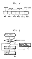
- addresses A n to A n+4 of random access memory 13 are used as the data area to count the time. This is represented in Fig. 4 in which the addresses to display the hours and minutes are represented and in which address A n is chosen to represent AM or PM. Each of these addresses, A n through A n+4 are formed as 4-bit addresses in this embodiment. Thus, the data at address A n+4 must be refreshed every minute. This is no problem when this information is stored at addresses in RAM 13, however, if there is a power interruption and the time data were to be transferred to nonvolatile random access memory 24 it must still be refreshed every minute.
- the present invention teaches the use of a nonvolatile memory only to store the data for controlling the television receiver but teaches the use of the random access memory already found in the micro-computer to store the time display data. This is only possible because the random access memory has a data holding voltage less than the operational voltage of the micro-computer and a system is provided to check whether the time data in the random access memory is correct and, if so, to use that data for display.
- a check code is provided with a special bit pattern, for example, "1010" at address A n+5 .
- the operation of the present invention is such that when the power switch of the television receiver is turned off, main data stored in random access memory 13 are automatically transferred to nonvolatile random access memory 24 but the time display are not transferred.
- both the main data and time display data will have been retained correctly in random access memory 13 by means of the standby power source circuit 33 maintaining the power on the micro-computer 10, even though relay contacts 22S are open.
- the problem arises when the plug 31 is pulled from the power socket or if the entire power line goes dead. In the event that voltage is removed from the input to power source circuit 33, the DC voltage V5 will drop, thereby triggering reset circuit 34.
- the triggering of reset circuit 34 then serves to start a predetermined operational routine that has been stored in read only memory 12. This routine will permit the time display data in random access memory 13 to be used in the event that the power outage exists only instantaneously.
- Fig. 5 is started at step 41 at the time that the central processing unit 11 is reset by reset circuit 34 during the period Tr due to the power failure and then the subsequent resumption of the power.
- step 42 it is checked whether or not the data at addresses A n to A n+5 are correct. This checking of data is carried out by determining whether or not the data at that address falls within a normal range. For example, as represented in Fig. 4, the clock data that indicates the tens digit in the minutes portion is data address A n+3 and by determining if the data at this address falls within the range of 0 to 5, then it can be judged whether that data is correct.
- step 42 the inventive routine then advances from step 42 to step 45 in which the main processing executed, as in normal operation. More specifically, because the timing data in RAM 13 are correct then the main data are also correct and such data can be used directly therefrom.
- step 42 when any one of the data at address A n through A n+5 is erroneous, for example, because of a long power failure, the routine advances from step 42 to step 43 at which initialization of time data is performed.
- This data is supplied to the time display means 23, whereby some indication, for example, "8888", flashes on and off thereby announcing the occurrence of a power failure.
- the processing routine then advances to step 44 where the data contained as backup data in the nonvolatile random access memory 24 are then transferred directly to random access memory 13 for subsequent transfer and supply to video output circuit 3, audio output circuit 5, and the channel selection control circuit 7. Thereafter, the routing moves to step 45 at which the main processing is executed.
- the data relating to the time display is regarded as correct and the time counting operation continues as it is, so that it is not necessary to provide a backup for the power source of the micro-computer 10 by means of a specially provided condenser or capacitor.
- the accuracy of such time display data is immediately checked, however.
- the manufacturing costs of such receiver are maintained at a constant level.
- nonvolatile random access memory even if a power failure occurs and lasts for a relatively long time, no problem is presented because the more important television receiver control data, such as channel selection data, sound volume data, and the like are provided in the backup nonvolatile random access memory. Also, when the power source of the micro-computer is backed up by a backup condenser, the capacitor voltage thereof may be reduced.
- the apparatus is such that the data holding voltage of the random access memory should be selected to be lower than the operation voltage of the micro-computer. Also, where data is to refreshed a number of times and can not be accomplished by means of a nonvolatile random access memory the invention provides a routine to follow using existing hardware.
Abstract
Description
- This invention relates generally to an apparatus for accommodating power failures in a micro-computer controlled electronic system, especially in a television receiver.
- Modern television receivers comprise an apparatus of the above mentioned type, said apparatus comprising:
- a RAM within said micro-computer, said RAM storing time display data and other data;
- a standby power source for supplying said micro-computer with power; and
- a reset circuit for resetting said micro-computer in case that the power as supplied from said standby power source resumes a level above the operating voltage of the micro-computer.
- Typically, such an apparatus additionally comprises a non-volatile memory into which data are transferred from said RAM in case of a power failure. When transferring the data, it makes no sense to transfer time display data. This, as nonvolatile memories typically use some sort of magnetic elements, such as bubble memory elements, which can generally only be accessed about 100,00 times in their lifetime. This is perfectly adequate to accommodate the number of times a television receiver is turned on and off, be it manually or by power failures, during its lifetime, which on the average is about 7 years, however, is not enough to stand this lifetime in case of updating time display data. Therefore, the power source is typically backed-up by a special, large value condenser or a capacitor bank to prevent the time display data in the RAM of the micro-computer from being erased when power failure occurs.
- An apparatus similar to the one described above, however, with no time display feature, is described in EP-A-0 043 462. In this apparatus the terminal voltage of a capacitor, which is provided for data holding purposes, is detected, when a main power source is connected, to judge whether data have extinguished from a memory. If this is the case, new data have to be input via a keyboard.
- Power failures can last for an appreciable period of time, such as they are caused by a storm or the like, however, in most cases the power failures are essentially instantaneous and are terminated within a second or less. Such power failures or brief outages may be caused by generator switch overs or network changes within the power grid, and brief power outages can also be caused in the home by rapid increases in load, such as when the motor of a refrigerator or air conditioner unit is suddenly switched on.
- It is the object of the present invention to provide an apparatus for accommodating power failures in a micro-computer controlled electronic system, which apparatus can save the time display information in most cases of power failures without requiring a large value condenser or capacitor bank.
- The apparatus of the present invention comprises the above listed features and is characterized in that:
- said RAM within said micro-computer has a data holding voltage lower than the operating voltage of said micro-computer and stores check data which are checked after a reset of said micro-computer as provided by said reset circuit, for using the time display data as stored in said RAM in case that the check data fulfil a predetermined checking condition; and
- said standby power source has a voltage-time-relation according to which its output power remains above said data holding voltage in case of brief dropouts of the main power supply.
- The apparatus of the present invention is able to save the time display information in case of the above mentioned typical brief power failures. This function is performed due to a RAM which has a data holding voltage which is lower than the operating voltage of the micro-computer, and due to a standby power source having a voltage-time-relation insuring that the voltage supplied in case of a power failure remains above the just mentioned data holding voltage during the time period of a typical brief voltage failure. For deciding whether the data holding voltage could be kept, the apparatus of the present invention does not check this voltage, but it checks whether a checking condition is fulfilled for predetermined stored checking data. Preferably, these checking data are the time display data themselves. In these data, the tens minute digit always has to have a value below "6" and the tens hour digit has to have a value below "2" in case that the voltage as supplied by the standby power source did not fall below the data holding voltage.
- The above and other objects, features, and advantages of the present invention will become apparent from the following datailed description of illustrated embodiments thereof to be read in conjunction with the accompanying drawings, in which like reference numerals designate like or similar elements and parts.
- Fig. 1 is a schematic in block diagram form of apparatus for use with a micro-computer controlled television receiver according to an embodiment of the present invention;
- Figs. 2A and 2B are useful in explaining the operation of the system of Fig. 1;
- Fig. 3 is a pictorial representation useful in explaining data transfer in the apparatus of Fig. 1;
- Fig. 4 is a pictorial representation of an arrangement of data used for time display in the apparatus of Fig. 1; and
- Fig. 5 is a flow chart representing the steps to be taken in the operation of the embodiment of the embodiment of the present invention as shown, for example, in Fig. 1.
- Fig. 1 schematically represents a portion of a micro-computer controlled television receiver and, more particularly,
reference numerals 1 through 7 designate those circuits that form the main receiving system of a television receiver. The television signal is received at the antenna AN and is supplied to atuner circuit 1, and the video intermediate frequency signal (IF) fromtuner 1 is fed through an intermediate frequency (IF)amplifier 2 to avideo output circuit 3, from which the three primary color signals are derived and fed to a colorcathode ray tube 4 for display. In addition, the intermediate frequency signal from theIF amplifier 2 is also supplied to anaudio output circuit 5, which derives the audio signal therefrom and feeds it to aloudspeaker 6. Tuning is typically achieved by means of a channel selection control circuit 7 that provides a tuning signal totuner circuit 1 so that the appropriate channel selection is carried out. - The micro-computer typically found in this type of digital television receiver carries out the control operations, such as channel selection and the like, and one form that micro-computer 10 may take is that of a one-chip micro-computer with four-bit data processing. Generally, micro-computer 10 includes a central processing unit 11 (CPU), a read only memory 12 (ROM), in which the various kinds of control programs are written, and a random access memory 13 (RAM) used as a work area and a data area. A plurality of
input ports 14 andoutput ports 15 typically found in micro-computers are also provided. As is well known, thesecircuit elements 12 through 15 making up micro-computer 10 are all connected to thecentral processing unit 11 by acommon bus 16. - Of course, television receivers typically include a number of function selecting and operating keys, and such keys are represented at 21A through 21N and are connected to micro-computer 10 through
input port 14. For example, tuning control to change the station by increasing or decreasing the channel number can be provided atkeys 21A, and such channel selection data would be stored inrandom access memory 13 and supplied throughoutput port 15 to control circuit 7, which provides a control voltage Vc that varies to tune the channel intuner 1. Similarly, other control signals are derived in response to operation ofkeys 21B through 21N, with the appropriate control signals being supplied through theinput ports 14 andoutput ports 15 tovideo output circuit 3 andaudio output circuit 5 for changing volume, picture contrast, hue, color, and the like. A mainpower source circuit 32 is provided and one ofkeys 21A through 21N would be the main power key, so that when the power key is depressed arelay 22 will be driven by a signal produced atoutput port 15 and therelay contacts 22S will be closed. As a result of the operation ofrelay 22, a standard utility AC voltage frompower source plug 31 is applied throughrelay contacts 22S to a mainpower source circuit 32 that produces a predetermined DC voltage used to operate the circuits of the television receiver. For example, the DC voltage generated by mainpower source circuit 32 would be supplied to all of thecircuits 1 through 7 as the respective operating voltages thereof. - A standby
power source circuit 33 is connected to the line voltage throughplug 31 and provides a DC voltage V5 that may be, for example, 5 volts. This DC voltage V5 is always supplied to micro-computer 10 as the operation voltage thereof, even when the television has been turned off, in order to keep the necessary data inRAM 13.Reset circuit 34 receives DC voltage V5 as the input voltage thereto and if DC voltage V5 drops to a voltage less than the operational voltage of micro-computer 10, which may be, for example, 4 volts,reset circuit 34 will detect this voltage drop and supply an output signal tocentral processing unit 11 as a reset signal therefor. Accordingly,central processing unit 11 is kept reset byreset circuit 34 during a time period in which the AC line voltage drops to an unacceptable limit. - Referring to Fig. 2A, the AC line voltage is arbitrarily shown as 100 volts and a brief period is shown during which the line voltage drops to zero volts before resuming the desired voltage level of 100 volts. Fig. 2B then represents the output from standby
power source circuit 33 as DC voltage V5 in which it is seen that in correspondence with the line voltage, the DC voltage V5 also drops below the operational voltage of 5 volts. Once the AC line voltage recovers, the DC voltage V5 then will resume its 5 volt operational level, and this period of time below the operational level is denoted as time period Tr. - Referring back to Fig. 1, a
waveform shaping circuit 35 has its input connected to standbypower source circuit 33 and generates a reference clock signal suitable for the clock data. In that regard, standbypower source circuit 33 provides an AC signal that has the line voltage frequency (50 or 60 cycles) but with a substantially reduced peak to peak voltage. Thus,waveform shaping circuit 35 squares the alternating current signal to a square wave signal that is supplied throughinput port 14 as the reference clock for counting the current time. This reference clock is counted bycentral processing unit 11 to form a signal indicating the current hour and minute, which is then supplied throughoutput port 15 to adigital time display 23 that displays the appropriate numerals. In addition to the display of the current time, an elapsed time count could be displayed and a so-called sleep timer could be implemented utilizing these same elements. - A nonvolatile
random access memory 24 is connected to micro-computer 10 throughinput ports 14 andoutput ports 15 such that when thepower source circuit 32 is switched off by operation of one of thekeys 21N, the channel data, volume data, and the like that are stored inrandom access memory 13 will be automatically transferred to nonvolatilerandom access memory 24 and stored therein even though therelay contacts 22S are open. This is the backup in case the power outage occurs, or theplug 31 is pulled out. In any event, however, according to the present invention the time display data is not transferred tononvolatile memory 24. - Fig. 3 is a pictorial representation of the data stored within
random access memory 13 being transferred to the nonvolatilerandom access memory 24 and back again. Because the standbypower source circuit 33 is connected to the main power line throughplug 31 at a point electrically before therelay contacts 22S even though the television receiver andpower source circuit 32 are switched off, micro-computer 10 will remain powered so that the data stored in theRAM 13 is not erased. Nevertheless, in the event that a power failure occurs orplug 31 is pulled out from the outlet, by which operation standbypower source circuit 33 is turned off, the drop in voltage V5, as represented in Fig. 2, is detected byreset circuit 34 andcentral processing unit 11 can be reset thereby, with the data stored in nonvolatilerandom access memory 24 being subsequently transferred torandom access memory 13 in accordance with a predetermined data transfer routine that is contained in readonly memory 12. Then, the data stored innonvolatile RAM 24 are effectively transferred to RAM 13 and thence tovideo output circuit 3,audio output circuit 5, and channel selection control circuit 7. Thus, even though the power to micro-computer 10 is interrupted by reason of a power failure or a disconnection from the AC power lines, and the micro-computer 10 stops operating completely, once the power is recovered, the television receiver is placed back into the original operative condition to commence receiving television signals. - In regard to the display of current time on
time display unit 23, addresses An to An+4 ofrandom access memory 13 are used as the data area to count the time. This is represented in Fig. 4 in which the addresses to display the hours and minutes are represented and in which address An is chosen to represent AM or PM. Each of these addresses, An through An+4 are formed as 4-bit addresses in this embodiment. Thus, the data at address An+4 must be refreshed every minute. This is no problem when this information is stored at addresses inRAM 13, however, if there is a power interruption and the time data were to be transferred to nonvolatilerandom access memory 24 it must still be refreshed every minute. This poses a problem with thisnonvolatile memory 24, because it can be accessed only around 100,000 times in its entire lifetime, the clock data cannot be rewritten in the non-volatilerandom access memory 24 every minute. Thus, the present invention teaches the use of a nonvolatile memory only to store the data for controlling the television receiver but teaches the use of the random access memory already found in the micro-computer to store the time display data. This is only possible because the random access memory has a data holding voltage less than the operational voltage of the micro-computer and a system is provided to check whether the time data in the random access memory is correct and, if so, to use that data for display. - As shown in Fig. 4, in addition to the addresses necessary to provide the digits for the hours and minutes, as well as the AM/PM indicator, a check code is provided with a special bit pattern, for example, "1010" at address An+5.
- The operation of the inventive apparatus will now set forth by means of the operational flow chart of Fig. 5, however, first some details relating to the operation of
standby circuit 33 are necessary. More particularly, referring back to Figs. 2A and 2B, when the main power line voltage drops to essentially zero volts and then recovers to its original voltage level, for example, 100 volts, although the DC voltage V5 as produced bystandby power circuit 33 also drops markedly from 5 volts, because of the time constant ofstandby power circuit 33, the voltage V5 will not drop all the way to zero if the main power line comes back to its original value within a short period of time. In that situation, as represented in Fig. 2B where the voltage V5 drops only to one volt, it has been found that if the random access memory is chosen correctly, then the data stored therein will not be erased and will be retained therein at the normal values when voltage V5 resumes its original value. On the other hand, when voltage V5 does drop all the way to zero, the data stored inrandom access memory 13 are erased regardless of the choice of data holding voltage. - In view of the above, the operation of the present invention is such that when the power switch of the television receiver is turned off, main data stored in
random access memory 13 are automatically transferred to nonvolatilerandom access memory 24 but the time display are not transferred. Note that if the television receiver is turned back on again, then both the main data and time display data will have been retained correctly inrandom access memory 13 by means of the standbypower source circuit 33 maintaining the power on the micro-computer 10, even thoughrelay contacts 22S are open. The problem, as pointed out above, arises when theplug 31 is pulled from the power socket or if the entire power line goes dead. In the event that voltage is removed from the input topower source circuit 33, the DC voltage V5 will drop, thereby triggeringreset circuit 34. The triggering ofreset circuit 34 then serves to start a predetermined operational routine that has been stored in read onlymemory 12. This routine will permit the time display data inrandom access memory 13 to be used in the event that the power outage exists only instantaneously. - More particularly, the steps in one such routine according to the present invention are shown in Fig. 5, which is started at
step 41 at the time that thecentral processing unit 11 is reset byreset circuit 34 during the period Tr due to the power failure and then the subsequent resumption of the power. Once the routine is started instep 41, it goes to step 42 at which it is checked whether or not the data at addresses An to An+5 are correct. This checking of data is carried out by determining whether or not the data at that address falls within a normal range. For example, as represented in Fig. 4, the clock data that indicates the tens digit in the minutes portion is data address An+3 and by determining if the data at this address falls within the range of 0 to 5, then it can be judged whether that data is correct. On the other hand, if the data at address An+3 is outside of these normal values, such as 8, then this data is judged to be incorrect. Similarly, there is a known limit for address An+1 since it can not go above 1. In addition, because the data at An+5 is known to be "1010", if that data is detected then the data is judged to be correct, whereas if that specific code is not detected the data is judged to be incorrect. As will be set forth below, if the data is correct it can be used directly fromRAM 13 once the power outage ends. - Thus, in the cases described above, because when an instantaneous power failure occurs the DC voltage V5 will rarely drop all the way to zero, if the data stored in
random access memory 13 are determined to be retained accurately therein, when the instantaneous power interruption ceases in most cases the data at addresses An through An+5 can be regarded as being correct data. - Therefore, if all the data are correct, which will be the situation in most cases of an instantaneous power failure, the inventive routine then advances from
step 42 to step 45 in which the main processing executed, as in normal operation. More specifically, because the timing data inRAM 13 are correct then the main data are also correct and such data can be used directly therefrom. - In the case, however, when any one of the data at address An through An+5 is erroneous, for example, because of a long power failure, the routine advances from
step 42 to step 43 at which initialization of time data is performed. This data is supplied to the time display means 23, whereby some indication, for example, "8888", flashes on and off thereby announcing the occurrence of a power failure. At such point, the processing routine then advances to step 44 where the data contained as backup data in the nonvolatilerandom access memory 24 are then transferred directly torandom access memory 13 for subsequent transfer and supply tovideo output circuit 3,audio output circuit 5, and the channel selection control circuit 7. Thereafter, the routing moves to step 45 at which the main processing is executed. - According to the present invention, as set forth hereinabove, when an instantaneous power failure occurs, the data relating to the time display is regarded as correct and the time counting operation continues as it is, so that it is not necessary to provide a backup for the power source of the micro-computer 10 by means of a specially provided condenser or capacitor. The accuracy of such time display data is immediately checked, however. In addition, because such backup is realized by a specific routine utilizing a read only memory and central processing unit already employed within a typical micro-computer controlled television receiver, the manufacturing costs of such receiver are maintained at a constant level.
- Moreover, by means of a nonvolatile random access memory, even if a power failure occurs and lasts for a relatively long time, no problem is presented because the more important television receiver control data, such as channel selection data, sound volume data, and the like are provided in the backup nonvolatile random access memory. Also, when the power source of the micro-computer is backed up by a backup condenser, the capacitor voltage thereof may be reduced.
- Thus, in keeping with the present invention, the apparatus is such that the data holding voltage of the random access memory should be selected to be lower than the operation voltage of the micro-computer. Also, where data is to refreshed a number of times and can not be accomplished by means of a nonvolatile random access memory the invention provides a routine to follow using existing hardware.
- The above description is provided for a single preferred embodiment of the invention, however, it will be apparent that many modifications and variations could be effected by one skilled in the art without departing from the scope of the novel concepts of the invention, which should be determined only by the appended claims.
Claims (6)
- An apparatus for accommodating power failures in a micro-computer controlled electronic system, said apparatus comprising:- a RAM (13) within said micro-computer (10), said RAM storing time display data and other data;- a standby power source (33) for supplying said micro-computer with power; and- a reset circuit (34) for resetting said micro-computer until the power as supplied from said standby power source resumes the operational level of the micro-computer;
characterized in that- said RAM within said micro-computer has a data holding voltage lower than the operating voltage of said micro-computer and stores check data which are checked after a reset of said micro-computer as provided by said reset circuit, for displaying the time display data as stored in said RAM in case that the check data fulfil a predetermined checking condition; and- said standby power source has a voltage-time-relation according to which its output power remains above said data holding voltage in case of brief dropouts of the main power supply. - An apparatus according to claim 1, characterized in that said check data comprise predetermined data and that the checking condition is whether said check data agree with said predetermined data.
- An apparatus according to one of the claims 1 or 2, characterized in that said check data comprise tens digit minute data and that the checking condition is whether said tens digit minute data are above "6".
- An apparatus according to one of the claims 1 to 3, characterized in that said check data comprise tens hour data and that the checking condition is whether this tens hour data are below "2".
- An apparatus according to one of the claims 1 to 4, characterized in that said electronic system is a micro-computer controlled television receiver.
- An apparatus according to one of the claims 1 to 5, characterized in that it comprises a nonvolatile RAM (24) for storing main data contained in said RAM, other than time data, and that said main data are transferred to said RAM from said nonvolatile RAM after the reset of said micro-computer (10).
Applications Claiming Priority (2)
| Application Number | Priority Date | Filing Date | Title |
|---|---|---|---|
| JP185353/85 | 1985-08-23 | ||
| JP60185353A JPH0746297B2 (en) | 1985-08-23 | 1985-08-23 | Electronics |
Publications (3)
| Publication Number | Publication Date |
|---|---|
| EP0213577A2 EP0213577A2 (en) | 1987-03-11 |
| EP0213577A3 EP0213577A3 (en) | 1988-10-26 |
| EP0213577B1 true EP0213577B1 (en) | 1993-10-20 |
Family
ID=16169302
Family Applications (1)
| Application Number | Title | Priority Date | Filing Date |
|---|---|---|---|
| EP86111668A Expired - Lifetime EP0213577B1 (en) | 1985-08-23 | 1986-08-22 | Apparatus providing data backup upon power failure in a micro-computer controlled television receiver |
Country Status (6)
| Country | Link |
|---|---|
| US (1) | US4750040A (en) |
| EP (1) | EP0213577B1 (en) |
| JP (1) | JPH0746297B2 (en) |
| AU (1) | AU595228B2 (en) |
| CA (1) | CA1299283C (en) |
| DE (1) | DE3689185T2 (en) |
Families Citing this family (33)
| Publication number | Priority date | Publication date | Assignee | Title |
|---|---|---|---|---|
| JP2522311B2 (en) * | 1987-07-08 | 1996-08-07 | ソニー株式会社 | Service mode setting method for electronic devices |
| US4858006A (en) * | 1987-07-28 | 1989-08-15 | Sony Corp. | Method and apparatus for establishing a servicing mode of an electronic apparatus |
| US5157270A (en) * | 1987-10-31 | 1992-10-20 | Canon Kabushiki Kaisha | Reset signal generating circuit |
| US5247692A (en) * | 1988-02-08 | 1993-09-21 | Nec Corporation | Multiple file system having a plurality of file units holding the same files in which loss of data is prevented in a failure of a file unit |
| US5021776A (en) * | 1988-07-11 | 1991-06-04 | Yale Security Inc. | Electronic combination of lock with changeable entry codes, lock-out and programming code |
| DE8817191U1 (en) * | 1988-07-28 | 1993-12-02 | Bosch Gmbh Robert | Arrangement for defined switching of a microcomputer in waiting mode |
| US5144441A (en) * | 1989-03-23 | 1992-09-01 | Thomson Consumer Electronics, Inc. | Quieting receiver during power interruption |
| DE69029005T2 (en) * | 1989-04-20 | 1997-05-28 | Sanyo Electric Co | Initialization process after power supply failure and associated process system |
| US4964011A (en) * | 1989-05-22 | 1990-10-16 | Databook, Inc. | Voltage transient protection circuit |
| JP2795906B2 (en) * | 1989-06-20 | 1998-09-10 | 株式会社東芝 | Tuning device |
| US5194954A (en) * | 1990-06-29 | 1993-03-16 | Thomson Consumer Electronics, Inc. | Automatic channel sampling picture-in-picture circuitry |
| JP3264919B2 (en) * | 1990-07-23 | 2002-03-11 | 松下電器産業株式会社 | Television receiver |
| US5390322A (en) * | 1991-02-01 | 1995-02-14 | O'brien; Michael J. | Apparatus and method for retaining cycle memory in electronic sterilizer controls |
| US5437040A (en) * | 1991-12-20 | 1995-07-25 | Codar Technology | Electronic system with variable threshold power failure signaling |
| KR0120191B1 (en) * | 1992-09-28 | 1997-10-30 | 윤종용 | Auto power-on method during noise set-off |
| DE4404131C2 (en) * | 1994-02-09 | 1998-07-23 | Siemens Ag | Battery-free data buffering |
| JPH07239795A (en) * | 1994-02-28 | 1995-09-12 | Sanyo Electric Co Ltd | Runaway preventing circuit for microprocessor |
| JP3701776B2 (en) * | 1997-08-05 | 2005-10-05 | アルプス電気株式会社 | In-vehicle electrical equipment with microcomputer |
| US6115079A (en) * | 1998-02-14 | 2000-09-05 | Mcrae; Michael W. | Programmable video channel controller |
| JP2000137607A (en) * | 1998-10-29 | 2000-05-16 | Sanyo Electric Co Ltd | Digital television receiver |
| EP1111347B1 (en) | 1999-12-15 | 2001-09-05 | Brown & Sharpe Tesa S.A. | Positional encoder |
| US7249282B2 (en) * | 2002-04-29 | 2007-07-24 | Thomson Licensing | Eeprom enable |
| US20030204857A1 (en) * | 2002-04-29 | 2003-10-30 | Dinwiddie Aaron Hal | Pre-power -failure storage of television parameters in nonvolatile memory |
| US7304689B2 (en) * | 2002-06-06 | 2007-12-04 | Microtune (Texas), L.P. | Single chip tuner for multi receiver applications |
| US20070192822A1 (en) * | 2006-02-13 | 2007-08-16 | Sbc Knowledge Ventures, L.P. | System and method of failure recovery for a television tuning device |
| JP4622950B2 (en) * | 2006-07-26 | 2011-02-02 | ソニー株式会社 | RECORDING DEVICE, RECORDING METHOD, RECORDING PROGRAM, IMAGING DEVICE, IMAGING METHOD, AND IMAGING PROGRAM |
| JP5241179B2 (en) * | 2007-09-07 | 2013-07-17 | キヤノン株式会社 | Projection display |
| WO2010049669A1 (en) * | 2008-10-27 | 2010-05-06 | Lifescan Scotland Limited | Methods and devices for mitigating esd events |
| US9660540B2 (en) | 2012-11-05 | 2017-05-23 | Flextronics Ap, Llc | Digital error signal comparator |
| US9494658B2 (en) * | 2013-03-14 | 2016-11-15 | Flextronics Ap, Llc | Approach for generation of power failure warning signal to maximize useable hold-up time with AC/DC rectifiers |
| US9490651B2 (en) | 2013-03-15 | 2016-11-08 | Flextronics Ap, Llc | Sweep frequency mode for magnetic resonant power transmission |
| US9621053B1 (en) | 2014-08-05 | 2017-04-11 | Flextronics Ap, Llc | Peak power control technique for primary side controller operation in continuous conduction mode |
| US9941799B1 (en) | 2014-08-08 | 2018-04-10 | Flextronics Ap, Llc | Cascade power system with isolated Class-E resonant circuit |
Family Cites Families (11)
| Publication number | Priority date | Publication date | Assignee | Title |
|---|---|---|---|---|
| US4281349A (en) * | 1980-04-29 | 1981-07-28 | Rca Corporation | Power supply arrangement for a tuning system |
| JPS5764398A (en) * | 1980-10-03 | 1982-04-19 | Olympus Optical Co Ltd | Memory device |
| US4422163A (en) * | 1981-09-03 | 1983-12-20 | Vend-A-Copy, Inc. | Power down circuit for data protection in a microprocessor-based system |
| JPS58139241A (en) * | 1982-02-10 | 1983-08-18 | Toshiba Corp | Picture memory access system |
| JPS5920025A (en) * | 1982-07-27 | 1984-02-01 | Toshiba Corp | Initializing device of semiconductor integrated circuit |
| US4523295A (en) * | 1982-09-07 | 1985-06-11 | Zenith Electronics Corporation | Power loss compensation for programmable memory control system |
| JPS60160333A (en) * | 1984-01-30 | 1985-08-21 | ソニー株式会社 | Electronic device |
| JPS6195629A (en) * | 1984-10-16 | 1986-05-14 | Sony Corp | Television receiver |
| JPS6199822A (en) * | 1984-10-22 | 1986-05-17 | Japan Atom Energy Res Inst | Device for detecting vacuum ultraviolet light |
| US4777626A (en) * | 1984-12-22 | 1988-10-11 | Tokyo Electric Co., Ltd. | Memory device having backup power supply |
| US4654717A (en) * | 1985-05-20 | 1987-03-31 | Rca Corporation | Cathode-ray tube arc-over protection for digital data in television display apparatus |
-
1985
- 1985-08-23 JP JP60185353A patent/JPH0746297B2/en not_active Expired - Lifetime
-
1986
- 1986-08-18 AU AU61560/86A patent/AU595228B2/en not_active Expired
- 1986-08-20 US US06/898,113 patent/US4750040A/en not_active Expired - Lifetime
- 1986-08-21 CA CA000516481A patent/CA1299283C/en not_active Expired - Lifetime
- 1986-08-22 EP EP86111668A patent/EP0213577B1/en not_active Expired - Lifetime
- 1986-08-22 DE DE86111668T patent/DE3689185T2/en not_active Expired - Fee Related
Also Published As
| Publication number | Publication date |
|---|---|
| JPS6246317A (en) | 1987-02-28 |
| EP0213577A3 (en) | 1988-10-26 |
| DE3689185D1 (en) | 1993-11-25 |
| CA1299283C (en) | 1992-04-21 |
| EP0213577A2 (en) | 1987-03-11 |
| US4750040A (en) | 1988-06-07 |
| AU6156086A (en) | 1987-02-26 |
| DE3689185T2 (en) | 1994-05-11 |
| AU595228B2 (en) | 1990-03-29 |
| JPH0746297B2 (en) | 1995-05-17 |
Similar Documents
| Publication | Publication Date | Title |
|---|---|---|
| EP0213577B1 (en) | Apparatus providing data backup upon power failure in a micro-computer controlled television receiver | |
| US4800336A (en) | Battery level indicator supplying data from a memory to a display in a power-off state | |
| US5424722A (en) | Device for displaying remaining electric energy of battery | |
| US5237698A (en) | Microcomputer | |
| US4580248A (en) | Electronic apparatus with memory backup system | |
| EP0141445A1 (en) | Stand-alone functional apparatus comprising a micro-computer | |
| JP4504804B2 (en) | Pre-power-out storage of TV jung parameters in non-volatile memory | |
| US5831347A (en) | Apparatus for determining if the duration of a power failure exceeded predetermined limits | |
| US5406272A (en) | Time setting and backup device for a battery-driven communications terminal and the method thereof | |
| EP0697791B1 (en) | Apparatus for determining if the duration of a power failure exceeded predetermined limits | |
| JP2001169465A (en) | Battery pack and real-time information delivery method | |
| JP2989076B2 (en) | Terminal network controller | |
| US7079006B1 (en) | Radio paging receiver and message erasing method | |
| EP0369782A2 (en) | Drive circuit for operating an appliance such as a printer | |
| US4943961A (en) | Memory retention system for volatile memory devices | |
| JPH10111737A (en) | Resetting device | |
| US5828704A (en) | Radio selective calling receiver | |
| JPH1155872A (en) | Charging monitor for backup battery | |
| US5357492A (en) | Apparatus for indicating times and/or date in portable recording unit | |
| US5416814A (en) | Elapsed time recording device | |
| JP2692093B2 (en) | Television receiver | |
| US4447160A (en) | Leap year compensation circuit | |
| JPH0230080B2 (en) | MEETASENSA | |
| JP3039122B2 (en) | Radio selective call receiver | |
| JPH0212417A (en) | Microprocessor initialization guarantee system |
Legal Events
| Date | Code | Title | Description |
|---|---|---|---|
| PUAI | Public reference made under article 153(3) epc to a published international application that has entered the european phase |
Free format text: ORIGINAL CODE: 0009012 |
|
| AK | Designated contracting states |
Kind code of ref document: A2 Designated state(s): DE FR GB NL |
|
| PUAL | Search report despatched |
Free format text: ORIGINAL CODE: 0009013 |
|
| AK | Designated contracting states |
Kind code of ref document: A3 Designated state(s): DE FR GB NL |
|
| 17P | Request for examination filed |
Effective date: 19881201 |
|
| 17Q | First examination report despatched |
Effective date: 19910408 |
|
| GRAA | (expected) grant |
Free format text: ORIGINAL CODE: 0009210 |
|
| AK | Designated contracting states |
Kind code of ref document: B1 Designated state(s): DE FR GB NL |
|
| REF | Corresponds to: |
Ref document number: 3689185 Country of ref document: DE Date of ref document: 19931125 |
|
| ET | Fr: translation filed | ||
| PLBE | No opposition filed within time limit |
Free format text: ORIGINAL CODE: 0009261 |
|
| STAA | Information on the status of an ep patent application or granted ep patent |
Free format text: STATUS: NO OPPOSITION FILED WITHIN TIME LIMIT |
|
| 26N | No opposition filed | ||
| PGFP | Annual fee paid to national office [announced via postgrant information from national office to epo] |
Ref country code: FR Payment date: 20010810 Year of fee payment: 16 |
|
| PGFP | Annual fee paid to national office [announced via postgrant information from national office to epo] |
Ref country code: DE Payment date: 20010813 Year of fee payment: 16 |
|
| PGFP | Annual fee paid to national office [announced via postgrant information from national office to epo] |
Ref country code: GB Payment date: 20010822 Year of fee payment: 16 |
|
| PGFP | Annual fee paid to national office [announced via postgrant information from national office to epo] |
Ref country code: NL Payment date: 20010830 Year of fee payment: 16 |
|
| REG | Reference to a national code |
Ref country code: GB Ref legal event code: IF02 |
|
| PG25 | Lapsed in a contracting state [announced via postgrant information from national office to epo] |
Ref country code: GB Free format text: LAPSE BECAUSE OF NON-PAYMENT OF DUE FEES Effective date: 20020822 |
|
| PG25 | Lapsed in a contracting state [announced via postgrant information from national office to epo] |
Ref country code: NL Free format text: LAPSE BECAUSE OF NON-PAYMENT OF DUE FEES Effective date: 20030301 Ref country code: DE Free format text: LAPSE BECAUSE OF NON-PAYMENT OF DUE FEES Effective date: 20030301 |
|
| GBPC | Gb: european patent ceased through non-payment of renewal fee |
Effective date: 20020822 |
|
| PG25 | Lapsed in a contracting state [announced via postgrant information from national office to epo] |
Ref country code: FR Free format text: LAPSE BECAUSE OF NON-PAYMENT OF DUE FEES Effective date: 20030430 |
|
| NLV4 | Nl: lapsed or anulled due to non-payment of the annual fee |
Effective date: 20030301 |
|
| REG | Reference to a national code |
Ref country code: FR Ref legal event code: ST |