EP0243835A1 - Measuring arrangement in systems with digital subsystems for registering voltage, current and phase angle - Google Patents
Measuring arrangement in systems with digital subsystems for registering voltage, current and phase angle Download PDFInfo
- Publication number
- EP0243835A1 EP0243835A1 EP87105767A EP87105767A EP0243835A1 EP 0243835 A1 EP0243835 A1 EP 0243835A1 EP 87105767 A EP87105767 A EP 87105767A EP 87105767 A EP87105767 A EP 87105767A EP 0243835 A1 EP0243835 A1 EP 0243835A1
- Authority
- EP
- European Patent Office
- Prior art keywords
- voltage
- current
- measuring arrangement
- phase angle
- systems
- Prior art date
- Legal status (The legal status is an assumption and is not a legal conclusion. Google has not performed a legal analysis and makes no representation as to the accuracy of the status listed.)
- Granted
Links
Images
Classifications
-
- G—PHYSICS
- G01—MEASURING; TESTING
- G01R—MEASURING ELECTRIC VARIABLES; MEASURING MAGNETIC VARIABLES
- G01R19/00—Arrangements for measuring currents or voltages or for indicating presence or sign thereof
- G01R19/175—Indicating the instants of passage of current or voltage through a given value, e.g. passage through zero
-
- G—PHYSICS
- G01—MEASURING; TESTING
- G01R—MEASURING ELECTRIC VARIABLES; MEASURING MAGNETIC VARIABLES
- G01R19/00—Arrangements for measuring currents or voltages or for indicating presence or sign thereof
- G01R19/25—Arrangements for measuring currents or voltages or for indicating presence or sign thereof using digital measurement techniques
-
- H—ELECTRICITY
- H03—ELECTRONIC CIRCUITRY
- H03K—PULSE TECHNIQUE
- H03K5/00—Manipulating of pulses not covered by one of the other main groups of this subclass
- H03K5/153—Arrangements in which a pulse is delivered at the instant when a predetermined characteristic of an input signal is present or at a fixed time interval after this instant
Definitions
- the invention relates to a measuring arrangement in digital systems for measuring alternating voltage, alternating current and phase angle by means of voltage converters and current converters which are connected on the secondary side to a multiplexer connected to the analog-digital converter.
- a difficulty with such measuring arrangements lies in the determination of the phase angle, that is to say in the exact detection of the point in time of the zero crossing of current and voltage, particularly when large measuring signal ranges are to be processed. This difficulty arises from the fact that a value approaching zero is practically impossible to measure.
- the object of the invention is therefore to provide a measuring arrangement in which this difficulty is avoided.
- This object is achieved in the measuring arrangement mentioned at the outset in that one pole of the secondary sides of the voltage and current transformers is at the potential of a reference voltage which is applied to the multiplexer as a reference variable for the voltage and current values to be measured.
- the advantage achieved with the invention lies primarily in the fact that it is hereby possible to exactly detect the point in time of the zero crossing of a measurement signal down to the smallest measurement signals. If, for example, a 10-bit AD converter is used, measurement signals up to 0.2% of the nominal value can still be processed. Another advantage is that temperature responses of the analog-digital converter and the reference voltage have no influence on the measurement accuracy to have.
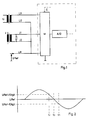
- the drawing shows an example of a measuring arrangement as a circuit diagram in FIG.
- a voltage converter (U) and a current converter (J) with one pole each (U1 and J1) are connected to a multiplexer (M).
- the other pole (U2 or J2) of the voltage transformer and current transformer is connected to a line (LR) which is supplied with a reference voltage (URef) and which is connected to the multiplexer (M) and serves as a reference variable for the voltage and current values to be measured .
- the multiplexer (M) is connected to the analog-to-digital converter (A / D).
- the control (C) of the digital system is carried out in the usual way.
- Figure 2 shows how the time of the zero crossing is appropriately detected.
- the time (Tv) for a measured value URef + 1 digit and the time (tn) for a measured value URef - 1 digit are recorded.
- the zero crossing can be calculated from
Abstract
Description
Die Erfindung bezieht sich auf eine Meßanordnung in digitalen Systemen zum Messen von Wechselspannung, Wechselstrom und Phasenwinkel mittels Spannungswandler und Stromwandler, die sekundärseitig an einem mit dem Analog-Digital-Wandler verbundenen Multiplexer angeschlossen sind.The invention relates to a measuring arrangement in digital systems for measuring alternating voltage, alternating current and phase angle by means of voltage converters and current converters which are connected on the secondary side to a multiplexer connected to the analog-digital converter.
Eine Schwierigkeit bei derartigen Meßanordnungen liegt in der Bestimmung des Phasenwinkels, also in der exakten Erfassung des Zeitpunktes des Nulldurchganges von Strom und Spannung, insbesondere dann, wenn große Meßsignalbereiche verarbeitet werden sollen. Diese Schwierigkeit begründet sich darin, daß ein gegen Null gehender Wert praktisch nicht meßbar ist.A difficulty with such measuring arrangements lies in the determination of the phase angle, that is to say in the exact detection of the point in time of the zero crossing of current and voltage, particularly when large measuring signal ranges are to be processed. This difficulty arises from the fact that a value approaching zero is practically impossible to measure.
Aufgabe der Erfindung ist es deshalb, eine Meßanordnung anzugeben, bei der diese Schwierigkeit vermieden wird. Diese Aufgabe wird bei der eingangs genannten Meßanordnung dadurch gelöst, daß jeweils ein Pol der Sekundärseiten von Spannungs- und Stromwandler am Potential einer Referenzspannung liegen, die dem Multiplexer als Bezugsgröße für die zu messenden Spannungs- und Stromwerte aufgeschaltet ist.The object of the invention is therefore to provide a measuring arrangement in which this difficulty is avoided. This object is achieved in the measuring arrangement mentioned at the outset in that one pole of the secondary sides of the voltage and current transformers is at the potential of a reference voltage which is applied to the multiplexer as a reference variable for the voltage and current values to be measured.
Der mit der Erfindung erzielte Vorteil liegt vor allem darin, daß es hiermit möglich ist, den Zeitpunkt des Nulldurchganges eines Meßsignals bis hin zu kleinsten Meßsignalen exakt zu erfassen. Wird z.B. ein 10-Bit AD-Wandler verwendet, können Meßsignale bis zu 0,2 % des Nennwertes noch verarbeitet werden. Weiter ist von Vorteil, daß Temperaturgänge des Analog-Digital-Wandlers und der Referenzspannung keinen Einfluß auf die Meßgenauigkeit haben.The advantage achieved with the invention lies primarily in the fact that it is hereby possible to exactly detect the point in time of the zero crossing of a measurement signal down to the smallest measurement signals. If, for example, a 10-bit AD converter is used, measurement signals up to 0.2% of the nominal value can still be processed. Another advantage is that temperature responses of the analog-digital converter and the reference voltage have no influence on the measurement accuracy to have.
Die Zeichnung zeigt in Figur 1 beispielhaft eine Meßanordnung als Schaltbild. Wie ersichtlich, sind ein Spannungswandler (U) und ein Stromwandler (J) mit je einem Pol (U1 bzw.J1) an einem Multiplexer (M) angeschlossen. Jeweils der andere Pol (U2 bzw. J2) von Spannungswandler und Stromwandler liegen an einer Leitung (LR), die mit einer Referenzspannung (URef) beaufschlagt ist und die am Mulitplexer (M) angeschlossen als Bezugsgröße für die zu messenden Spannungs- und Stromwerte dient. Der Multiplexer (M) ist mit dem Analog-Digital-Wandler (A/D) verbunden. Die Ansteuerung (C) des Digitalsystems erfolgt auf übliche Weise.The drawing shows an example of a measuring arrangement as a circuit diagram in FIG. As can be seen, a voltage converter (U) and a current converter (J) with one pole each (U1 and J1) are connected to a multiplexer (M). The other pole (U2 or J2) of the voltage transformer and current transformer is connected to a line (LR) which is supplied with a reference voltage (URef) and which is connected to the multiplexer (M) and serves as a reference variable for the voltage and current values to be measured . The multiplexer (M) is connected to the analog-to-digital converter (A / D). The control (C) of the digital system is carried out in the usual way.
Figur 2 zeigt, wie der Zeitpunkt des Nulldurchganges zweckmäßiger Weise erfaßt wird. Meßtechnisch erfaßt werden hierbei der Zeitpunkt (Tv) bei einem Meßwert URef + 1 Digit und der Zeitpunkt (tn) bei einem Meßwert URef - 1 Digit. Der Nulldurchgang läßt sich berechnen nach
Claims (1)
Priority Applications (1)
| Application Number | Priority Date | Filing Date | Title |
|---|---|---|---|
| AT87105767T ATE64014T1 (en) | 1986-04-29 | 1987-04-18 | MEASUREMENT ARRANGEMENT IN SYSTEMS WITH DIGITAL SUB-ASSEMBLIES FOR DETECTING VOLTAGE, CURRENT AND PHASE ANGLE. |
Applications Claiming Priority (2)
| Application Number | Priority Date | Filing Date | Title |
|---|---|---|---|
| DE3614419 | 1986-04-29 | ||
| DE19863614419 DE3614419A1 (en) | 1986-04-29 | 1986-04-29 | MEASURING ARRANGEMENT IN DIGITAL SYSTEMS FOR DETECTING VOLTAGE, CURRENT AND PHASE ANGLE |
Publications (2)
| Publication Number | Publication Date |
|---|---|
| EP0243835A1 true EP0243835A1 (en) | 1987-11-04 |
| EP0243835B1 EP0243835B1 (en) | 1991-05-29 |
Family
ID=6299745
Family Applications (1)
| Application Number | Title | Priority Date | Filing Date |
|---|---|---|---|
| EP87105767A Expired - Lifetime EP0243835B1 (en) | 1986-04-29 | 1987-04-18 | Measuring arrangement in systems with digital subsystems for registering voltage, current and phase angle |
Country Status (4)
| Country | Link |
|---|---|
| EP (1) | EP0243835B1 (en) |
| JP (1) | JPS62267671A (en) |
| AT (1) | ATE64014T1 (en) |
| DE (2) | DE3614419A1 (en) |
Cited By (3)
| Publication number | Priority date | Publication date | Assignee | Title |
|---|---|---|---|---|
| EP0332881A1 (en) * | 1988-03-16 | 1989-09-20 | Asea Brown Boveri Ag | Process and appliance for digital measuring |
| WO1994003818A1 (en) * | 1991-12-13 | 1994-02-17 | The Dow Chemical Company | High speed power analyzer |
| EP0691545A1 (en) * | 1994-07-08 | 1996-01-10 | MASCHINENFABRIK REINHAUSEN GmbH | Process and appliance in digital systems for measuring alternating voltage, current and phase angle of a signal |
Families Citing this family (4)
| Publication number | Priority date | Publication date | Assignee | Title |
|---|---|---|---|---|
| JPH0333378U (en) * | 1989-08-07 | 1991-04-02 | ||
| FI93256C (en) * | 1993-06-21 | 1995-03-10 | Tamrock Oy | Equipment for handling drill rods |
| DE19642871C2 (en) * | 1996-10-17 | 2001-06-13 | Reinhausen Maschf Scheubeck | Measuring circuit for voltage regulators |
| CN108152572B (en) * | 2017-12-29 | 2021-05-07 | 苏州英威腾电力电子有限公司 | Current Hall detection method and device for grid-connected converter |
Citations (1)
| Publication number | Priority date | Publication date | Assignee | Title |
|---|---|---|---|---|
| US4459546A (en) * | 1980-11-03 | 1984-07-10 | Rockwell International Corporation | Electronic kilowatthour meter |
Family Cites Families (3)
| Publication number | Priority date | Publication date | Assignee | Title |
|---|---|---|---|---|
| US3786338A (en) * | 1970-01-27 | 1974-01-15 | Technical Management Services | Transformer for direct and/or alternating currents |
| CH557033A (en) * | 1972-09-04 | 1974-12-13 | Bauer Messinstrumente Ag | PROCEDURE AND EQUIPMENT FOR THE DERIVATION OF DIGITAL MEASUREMENTS ON ELECTRICITY NETWORKS. |
| DE3126485A1 (en) * | 1981-07-04 | 1983-01-20 | Metrawatt GmbH, 8500 Nürnberg | Measuring arrangement |
-
1986
- 1986-04-29 DE DE19863614419 patent/DE3614419A1/en active Granted
-
1987
- 1987-04-18 AT AT87105767T patent/ATE64014T1/en not_active IP Right Cessation
- 1987-04-18 DE DE8787105767T patent/DE3770328D1/en not_active Expired - Fee Related
- 1987-04-18 EP EP87105767A patent/EP0243835B1/en not_active Expired - Lifetime
- 1987-04-28 JP JP62103418A patent/JPS62267671A/en active Pending
Patent Citations (1)
| Publication number | Priority date | Publication date | Assignee | Title |
|---|---|---|---|---|
| US4459546A (en) * | 1980-11-03 | 1984-07-10 | Rockwell International Corporation | Electronic kilowatthour meter |
Non-Patent Citations (4)
| Title |
|---|
| ELEKTOR, Band 11, Nr. 7/8, Juli-August 1985, Seite 7-69, Canterbury, GB; "Simple zero crossing detector" * |
| ELEKTRONIK, Band 31, Nr. 14, Juli 1982, Seite 61, München, DE; U. KREBS: "Nullspannungsdetektor mit NE 555" * |
| IBM TECHNICAL DISCLOSURE BULLETIN, Band 18, Nr. 1, 1975, Seite 144, New York, US; H. BRAQUET et al.: "Zero-crossing detector" * |
| POLYTECHNISCH TIJDSCHRIFT/ELEKTROTECHNIEK ELEKTRONICA, Band 39, Nr. 1, Januar 1983, Seiten 13-17, Rijswijk, NL; W. TEBRA: "Standaarden en kalibratie-apparatuur" * |
Cited By (4)
| Publication number | Priority date | Publication date | Assignee | Title |
|---|---|---|---|---|
| EP0332881A1 (en) * | 1988-03-16 | 1989-09-20 | Asea Brown Boveri Ag | Process and appliance for digital measuring |
| WO1994003818A1 (en) * | 1991-12-13 | 1994-02-17 | The Dow Chemical Company | High speed power analyzer |
| EP0691545A1 (en) * | 1994-07-08 | 1996-01-10 | MASCHINENFABRIK REINHAUSEN GmbH | Process and appliance in digital systems for measuring alternating voltage, current and phase angle of a signal |
| AU692516B2 (en) * | 1994-07-08 | 1998-06-11 | Maschinenfabrik Reinhausen Gmbh | Method and means for signal processing for parameter measurement |
Also Published As
| Publication number | Publication date |
|---|---|
| DE3614419C2 (en) | 1991-02-07 |
| DE3770328D1 (en) | 1991-07-04 |
| DE3614419A1 (en) | 1987-11-26 |
| JPS62267671A (en) | 1987-11-20 |
| EP0243835B1 (en) | 1991-05-29 |
| ATE64014T1 (en) | 1991-06-15 |
Similar Documents
| Publication | Publication Date | Title |
|---|---|---|
| DE2945895A1 (en) | MAGNETIC LENGTH MEASURING SYSTEM PREFERABLY FOR MEASURING THE POSITION OF HYDRAULIC AND PNEUMATIC CYLINDERS | |
| HU198250B (en) | Device for measuring voltage in magnetic field | |
| EP0294590B1 (en) | Compensation principle current sensor | |
| EP0243835B1 (en) | Measuring arrangement in systems with digital subsystems for registering voltage, current and phase angle | |
| EP0058050B1 (en) | Measuring method | |
| DE2632377C2 (en) | ||
| DE4204515A1 (en) | Measurement of electric currents esp. in high and medium voltage supply mains - using Rogowski coil with measurements from coil digitised and integrated in computer unit which with over-supply of digital signals reduces signal paths | |
| DE2153121A1 (en) | Impedance measuring circuit | |
| DE1803457C3 (en) | Overload protection for jib cranes | |
| DE3734912C2 (en) | ||
| DE4142342C2 (en) | Method and device for digital current measurement | |
| DE2120911C3 (en) | Method and circuit arrangement for digitally measuring the voltage of an electrical signal | |
| DE1015614B (en) | Electric length measuring device | |
| DE19715991A1 (en) | Adjustment detector with magnetic sensor | |
| DE2508033A1 (en) | Measurement of capacitance and loss factor - using automatic range finding network involving relays and comparators | |
| DE3027800C2 (en) | Circuit arrangement to avoid interference voltages during measurements with DC Murray bridge circuits on cables | |
| SU879273A1 (en) | Reference signal pickup for checking transformer converters of displacement | |
| DE942759C (en) | Device for measuring loss angles and large capacities by comparing them with a known capacitance with a current transformer and an alternating current measuring bridge | |
| EP0347649A1 (en) | Device for measuring the fluid-flow rate of an electrically conductive fluid | |
| SU947624A1 (en) | Capacitive displacement meter | |
| DE4419228B4 (en) | Device for strain measurement | |
| DE3816568A1 (en) | METHOD AND DEVICE FOR DEMODULATING AN AC VOLTAGE SIGNAL | |
| RU1800422C (en) | Device for electric defects of insulation of underground pipelines | |
| DD243341A1 (en) | ELECTRONIC TILTING KNIFE | |
| DE3428392A1 (en) | DC sensor |
Legal Events
| Date | Code | Title | Description |
|---|---|---|---|
| PUAI | Public reference made under article 153(3) epc to a published international application that has entered the european phase |
Free format text: ORIGINAL CODE: 0009012 |
|
| AK | Designated contracting states |
Kind code of ref document: A1 Designated state(s): AT DE FR GB SE |
|
| EL | Fr: translation of claims filed | ||
| 17P | Request for examination filed |
Effective date: 19880409 |
|
| RAP1 | Party data changed (applicant data changed or rights of an application transferred) |
Owner name: MASCHINENFABRIK REINHAUSEN GMBH |
|
| 17Q | First examination report despatched |
Effective date: 19900918 |
|
| GRAA | (expected) grant |
Free format text: ORIGINAL CODE: 0009210 |
|
| AK | Designated contracting states |
Kind code of ref document: B1 Designated state(s): AT DE FR GB SE |
|
| REF | Corresponds to: |
Ref document number: 64014 Country of ref document: AT Date of ref document: 19910615 Kind code of ref document: T |
|
| REF | Corresponds to: |
Ref document number: 3770328 Country of ref document: DE Date of ref document: 19910704 |
|
| ET | Fr: translation filed | ||
| GBT | Gb: translation of ep patent filed (gb section 77(6)(a)/1977) | ||
| PLBE | No opposition filed within time limit |
Free format text: ORIGINAL CODE: 0009261 |
|
| STAA | Information on the status of an ep patent application or granted ep patent |
Free format text: STATUS: NO OPPOSITION FILED WITHIN TIME LIMIT |
|
| 26N | No opposition filed | ||
| EAL | Se: european patent in force in sweden |
Ref document number: 87105767.5 |
|
| PGFP | Annual fee paid to national office [announced via postgrant information from national office to epo] |
Ref country code: SE Payment date: 19980416 Year of fee payment: 12 |
|
| PGFP | Annual fee paid to national office [announced via postgrant information from national office to epo] |
Ref country code: GB Payment date: 19980417 Year of fee payment: 12 |
|
| PGFP | Annual fee paid to national office [announced via postgrant information from national office to epo] |
Ref country code: AT Payment date: 19980427 Year of fee payment: 12 |
|
| PGFP | Annual fee paid to national office [announced via postgrant information from national office to epo] |
Ref country code: FR Payment date: 19980430 Year of fee payment: 12 |
|
| PGFP | Annual fee paid to national office [announced via postgrant information from national office to epo] |
Ref country code: DE Payment date: 19980603 Year of fee payment: 12 |
|
| PG25 | Lapsed in a contracting state [announced via postgrant information from national office to epo] |
Ref country code: GB Free format text: LAPSE BECAUSE OF NON-PAYMENT OF DUE FEES Effective date: 19990418 Ref country code: AT Free format text: LAPSE BECAUSE OF NON-PAYMENT OF DUE FEES Effective date: 19990418 |
|
| PG25 | Lapsed in a contracting state [announced via postgrant information from national office to epo] |
Ref country code: SE Free format text: LAPSE BECAUSE OF NON-PAYMENT OF DUE FEES Effective date: 19990419 |
|
| GBPC | Gb: european patent ceased through non-payment of renewal fee |
Effective date: 19990418 |
|
| PG25 | Lapsed in a contracting state [announced via postgrant information from national office to epo] |
Ref country code: FR Free format text: LAPSE BECAUSE OF NON-PAYMENT OF DUE FEES Effective date: 19991231 |
|
| EUG | Se: european patent has lapsed |
Ref document number: 87105767.5 |
|
| REG | Reference to a national code |
Ref country code: FR Ref legal event code: ST |
|
| PG25 | Lapsed in a contracting state [announced via postgrant information from national office to epo] |
Ref country code: DE Free format text: LAPSE BECAUSE OF NON-PAYMENT OF DUE FEES Effective date: 20000201 |