EP0252184A1 - Pit cover meter reader - Google Patents
Pit cover meter reader Download PDFInfo
- Publication number
- EP0252184A1 EP0252184A1 EP86115258A EP86115258A EP0252184A1 EP 0252184 A1 EP0252184 A1 EP 0252184A1 EP 86115258 A EP86115258 A EP 86115258A EP 86115258 A EP86115258 A EP 86115258A EP 0252184 A1 EP0252184 A1 EP 0252184A1
- Authority
- EP
- European Patent Office
- Prior art keywords
- sensor
- meter
- face plate
- wall
- enclosure
- Prior art date
- Legal status (The legal status is an assumption and is not a legal conclusion. Google has not performed a legal analysis and makes no representation as to the accuracy of the status listed.)
- Withdrawn
Links
- 230000001939 inductive effect Effects 0.000 claims abstract description 8
- 230000008878 coupling Effects 0.000 claims abstract description 7
- 238000010168 coupling process Methods 0.000 claims abstract description 7
- 238000005859 coupling reaction Methods 0.000 claims abstract description 7
- 238000013500 data storage Methods 0.000 claims abstract 4
- 239000012530 fluid Substances 0.000 claims 1
- XLYOFNOQVPJJNP-UHFFFAOYSA-N water Substances O XLYOFNOQVPJJNP-UHFFFAOYSA-N 0.000 description 8
- 238000009434 installation Methods 0.000 description 5
- 230000001154 acute effect Effects 0.000 description 1
- 230000008014 freezing Effects 0.000 description 1
- 238000007710 freezing Methods 0.000 description 1
- 239000000463 material Substances 0.000 description 1
Images
Classifications
-
- G—PHYSICS
- G08—SIGNALLING
- G08C—TRANSMISSION SYSTEMS FOR MEASURED VALUES, CONTROL OR SIMILAR SIGNALS
- G08C17/00—Arrangements for transmitting signals characterised by the use of a wireless electrical link
- G08C17/04—Arrangements for transmitting signals characterised by the use of a wireless electrical link using magnetically coupled devices
-
- G—PHYSICS
- G01—MEASURING; TESTING
- G01D—MEASURING NOT SPECIALLY ADAPTED FOR A SPECIFIC VARIABLE; ARRANGEMENTS FOR MEASURING TWO OR MORE VARIABLES NOT COVERED IN A SINGLE OTHER SUBCLASS; TARIFF METERING APPARATUS; MEASURING OR TESTING NOT OTHERWISE PROVIDED FOR
- G01D4/00—Tariff metering apparatus
- G01D4/002—Remote reading of utility meters
- G01D4/006—Remote reading of utility meters to a non-fixed location, i.e. mobile location
-
- H—ELECTRICITY
- H04—ELECTRIC COMMUNICATION TECHNIQUE
- H04B—TRANSMISSION
- H04B5/00—Near-field transmission systems, e.g. inductive loop type
-
- H04B5/73—
-
- H04B5/77—
-
- Y—GENERAL TAGGING OF NEW TECHNOLOGICAL DEVELOPMENTS; GENERAL TAGGING OF CROSS-SECTIONAL TECHNOLOGIES SPANNING OVER SEVERAL SECTIONS OF THE IPC; TECHNICAL SUBJECTS COVERED BY FORMER USPC CROSS-REFERENCE ART COLLECTIONS [XRACs] AND DIGESTS
- Y02—TECHNOLOGIES OR APPLICATIONS FOR MITIGATION OR ADAPTATION AGAINST CLIMATE CHANGE
- Y02B—CLIMATE CHANGE MITIGATION TECHNOLOGIES RELATED TO BUILDINGS, e.g. HOUSING, HOUSE APPLIANCES OR RELATED END-USER APPLICATIONS
- Y02B90/00—Enabling technologies or technologies with a potential or indirect contribution to GHG emissions mitigation
- Y02B90/20—Smart grids as enabling technology in buildings sector
-
- Y—GENERAL TAGGING OF NEW TECHNOLOGICAL DEVELOPMENTS; GENERAL TAGGING OF CROSS-SECTIONAL TECHNOLOGIES SPANNING OVER SEVERAL SECTIONS OF THE IPC; TECHNICAL SUBJECTS COVERED BY FORMER USPC CROSS-REFERENCE ART COLLECTIONS [XRACs] AND DIGESTS
- Y04—INFORMATION OR COMMUNICATION TECHNOLOGIES HAVING AN IMPACT ON OTHER TECHNOLOGY AREAS
- Y04S—SYSTEMS INTEGRATING TECHNOLOGIES RELATED TO POWER NETWORK OPERATION, COMMUNICATION OR INFORMATION TECHNOLOGIES FOR IMPROVING THE ELECTRICAL POWER GENERATION, TRANSMISSION, DISTRIBUTION, MANAGEMENT OR USAGE, i.e. SMART GRIDS
- Y04S20/00—Management or operation of end-user stationary applications or the last stages of power distribution; Controlling, monitoring or operating thereof
- Y04S20/30—Smart metering, e.g. specially adapted for remote reading
Definitions
- This invention relates to the reading of utility meters which are located outside of the residence in pits below the surface of the ground.
- a long standing problem in the utility industry is the economic reading of utility meters without inconvenience to the home owner.
- the problem is especially acute in connection with the reading of water meters.
- the reading of such meter installations presents a number of problems in that it may cause inconvenience to the homeowner, or the homeowner may be absent at the time the individual taking meter readings is making his rounds making it necessary to subsequently revisit such residences, or delay taking the reading until the next regularly scheduled visit or request the homeowner to take the reading visually and send it to the utility on forms provided by the utility.
- Another approach to the problem has been to provide the meter within the residence with an encoded register with storage means in which data representative of volumetric flow through the meter is accumulated.
- the output from the encoded register is then connected to a receptacle located outside of the building.
- a readout device is carried by the person taking the reading and by plugging the readout device into the receptacle thereby connecting the readout device with the output of the encoded register so that the data stored in the register is downloaded into the readout device.
- An interrogation signal is sent by the portable interrogator/storage unit through the inductively coupled coils to the encoded register at the meter, which in response to the interrogation signal transmits the data accumulated by the encoder through the inductive coupling into the portable interrogator/storage unit.
- the system described immediately above has the advantage of economical and error-free recording of data accumulated by the meter encoder.
- the entire meter is located outside of the residence within a pit below the surface of the ground.
- it is current practice to locate the meter sensor unit on the meter itself which of course is below the level of the ground within the pit.
- the individual taking the reading is equipped with an interrogator/storage unit and a portable sensor as described above but which in such cases would be located at the end of an extension rod.
- the individual taking the reading then removes the pit cover and extends the portable sensor into the pit until it is in close enough proximity with the sensor on the meter to establish an inductive coupling between the two coils located respectively within the meter sensor and the portable sensor.
- Such an arrangement is shown in Bulletin W-1500 published by the Municipal and Control Division of the Rockwell International Corporation.
- Applicants have devised a meter reading system in which the meter sensor is located in the cover of the pit in which the meter itself is installed.
- the individual performing the reading operation then carries a portable interrogator/storage unit and the portable sensor is located at the end of an extension rod.
- the portable interrogator sensor then is brought into close proximity to the meter sensor located on the pit cover in order to achieve an inductive coupling between the two coils located respectively in the two sensors whereby data accumulated in the encoded register at the meter may be transmitted from the register via the two sensors into the interrogator/storage unit where it is stored until downloaded by equipment installed at the utilities premises.
- Figure 1 shows an underground chamber or pit 10 the walls and floor 12 of which are formed of some suitable material such as masonry.
- a water meter 14 is installed together with an encoded register 16 driven by the flow responsive element within the meter 14.
- the encoded register 16 is comprised of a water tight housing which encloses several digit wheels driven by the meter flow responsive element to indicate the volume of water having flowed through the meter. The position of each digit wheel is sensed by suitable electric circuitry such as that as described in co-pending application for U. S. patent of Bruce Gray, Serial No. 510,753 filed July 1, 1983.
- register 16 The output of register 16 is electrically connected by means of a waterproof cord 18 to a meter sensor designated generally by the numeral 20 located in the pit cover 22 which is removable or hinged to the top of the pit.
- the sensor assembly 20 is comprised of a housing 30 which in turn is comprised of a face plate 32 which has a downwardly extending tubular extension 34.
- the tubular extension 34 has an exterior threaded section 36 and projects through an opening 38 in the pit cover 22.
- a locking nut 40 is threaded onto the threaded section 36 from the inside of the cover 22 so as to clamp the portion of the cover 22 surrounding the opening 38 between face plate 32 and locking nut 40.
- a passage 44 extends axially through housing 30 and an annular shoulder 42 is formed in the face plate 32 around the upper end of the passage 44.
- the meter sensor 46 is received within the passage 44 so that its upper end abuts against shoulder 42 in face plate 32 when in place in the assembly.
- the passage 44 is internally threaded to receive a threaded tube 52 to clamp the sensor 46 between shoulder 42 in face plate 32 and the end of the tube 52.
- a circular recess 54 is formed in the upper surface of face plate 32 by uniformly spaced radially extending sloping raised portions 56.
- the sensor 46 contains an inductive coil sealed within the sensor which is electrically connected to the register 16 (Fig. 1) by means of cord 18.
- an interrogator sensor 60 is contained within a housing 62 which is mounted on the end of extension 66 by means of a universal joint 64 to facilitate alignment of housing 62 in recess 54.
- housing 62 is fully inserted into recess 54 the sensors 46 and 60 will be inductively coupled.
- the housing 62 is of a size to snugly fit into recess 54 to thereby guide the sensor 60 into a good inductive coupling with sensor 46.
- the extension rod 66 is carried by an individual 68 who takes the meter reading.
- the individual also carries an interrogator/storage unit 70 which is connected by suitable wiring 72 extending through extension 66 to the coil within the sensor 60.
- the individual 68 In order to read the data accumulated by the encoded register 16, the individual 68 merely inserts the housing 62 into the recess 54. He then operates a switch on the handle 65 of the upper end of extension 66 to cause an interrogation signal to be sent through the sensor 60 and sensor 46 to the encoded register 16. Upon receipt of the interrogation signal the encoded register causes a signal to be sent back through sensors 46 and 60 to the interrogation/storage unit 70 which signal contains an identification of the particular meter being interrogated and digital data representative of the volumetric flow through the meter accumulated by the register.
Abstract
Description
- This invention relates to the reading of utility meters which are located outside of the residence in pits below the surface of the ground.
- A long standing problem in the utility industry is the economic reading of utility meters without inconvenience to the home owner. The problem is especially acute in connection with the reading of water meters. In those areas which are subject to freezing temperatures it has in the past been necessary to install the meters within the residence to prevent damage to the meter when the water within it freezes. However, the reading of such meter installations presents a number of problems in that it may cause inconvenience to the homeowner, or the homeowner may be absent at the time the individual taking meter readings is making his rounds making it necessary to subsequently revisit such residences, or delay taking the reading until the next regularly scheduled visit or request the homeowner to take the reading visually and send it to the utility on forms provided by the utility.
- One solution to these problems utilized in the past was to provide a remote register which is located outside of the residence preferably on an exterior wall of the residence, the register then being electrically connected to a device on the meter within the residence which produces pulses or other electrical signals representative of the volumetric flow of water through the meter. An example of such an installation is the system shown in U. S. Patent No. 3,228,244 to Weinberger et al.
- Another approach to the problem has been to provide the meter within the residence with an encoded register with storage means in which data representative of volumetric flow through the meter is accumulated. The output from the encoded register is then connected to a receptacle located outside of the building. A readout device is carried by the person taking the reading and by plugging the readout device into the receptacle thereby connecting the readout device with the output of the encoded register so that the data stored in the register is downloaded into the readout device. Such a system is shown in the U. S. Patent No. 3,806,904 to Weinberger et al.
- An improvement in the means of transferring the register data from the register to the readout device is disclosed in a co-pending application for U. S. Patent of Felix M. Sciulli Serial No. 505,032 filed June 30, 1983. In the arrangement shown there a coil located within a stationary sealed sensor housing is located on the exterior of the building and is electrically connected to the output of an encoded register located at the meter within the building. The individual taking the reading is equipped with a portable sensor comprised of a second coil located within the portable sealed sensor housing, the second coil being connected to an interrogator/storage unit which is carried by the individual. In order to read the meter the portable sensing unit is brought into close proximity with the sensor unit on the building so as to inductively couple the two coils in the manner of a transformer. An interrogation signal is sent by the portable interrogator/storage unit through the inductively coupled coils to the encoded register at the meter, which in response to the interrogation signal transmits the data accumulated by the encoder through the inductive coupling into the portable interrogator/storage unit.
- The system described immediately above has the advantage of economical and error-free recording of data accumulated by the meter encoder. In some areas however, the entire meter is located outside of the residence within a pit below the surface of the ground. In such cases it is current practice to locate the meter sensor unit on the meter itself which of course is below the level of the ground within the pit. To read the meter the individual taking the reading is equipped with an interrogator/storage unit and a portable sensor as described above but which in such cases would be located at the end of an extension rod. The individual taking the reading then removes the pit cover and extends the portable sensor into the pit until it is in close enough proximity with the sensor on the meter to establish an inductive coupling between the two coils located respectively within the meter sensor and the portable sensor. Such an arrangement is shown in Bulletin W-1500 published by the Municipal and Control Division of the Rockwell International Corporation.
- While such an arrangement makes it relatively convenient to read the meter within the pit it is nevertheless subject to several disadvantages. The individual taking the meter reading must of course first remove the pit cover. Often times the cover may be difficult to remove having been frozen in place or otherwise made difficult of removal. Also, often times in low lying areas or in moist climate the pits may become inundated with water making it difficult to get a reading. In order to avoid these difficulties Applicants have devised an arrangement in which the meter sensor is located in the cover of the pit and is electrically connected to the encoder on the meter. This enables the individual taking the meter reading to bring the portable sensor into close proximity with the meter sensor on the pit cover without necessity of opening the pit cover.
- In order to eliminate the problems inherent in the prior art pit meter installations described above, Applicants have devised a meter reading system in which the meter sensor is located in the cover of the pit in which the meter itself is installed. The individual performing the reading operation then carries a portable interrogator/storage unit and the portable sensor is located at the end of an extension rod. The portable interrogator sensor then is brought into close proximity to the meter sensor located on the pit cover in order to achieve an inductive coupling between the two coils located respectively in the two sensors whereby data accumulated in the encoded register at the meter may be transmitted from the register via the two sensors into the interrogator/storage unit where it is stored until downloaded by equipment installed at the utilities premises.
-
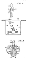
- Figure 1 shows a pit meter installation with the meter sensor located in the removable pit cover and showing the individual taking a meter reading.
- Figure 2 shows the detail of the meter sensor which is located in the pit cover.
- Referring to the drawings, Figure 1 shows an underground chamber or
pit 10 the walls andfloor 12 of which are formed of some suitable material such as masonry. At the bottom of the pit awater meter 14 is installed together with an encodedregister 16 driven by the flow responsive element within themeter 14. It will be understood that the encodedregister 16 is comprised of a water tight housing which encloses several digit wheels driven by the meter flow responsive element to indicate the volume of water having flowed through the meter. The position of each digit wheel is sensed by suitable electric circuitry such as that as described in co-pending application for U. S. patent of Bruce Gray, Serial No. 510,753 filed July 1, 1983. - The output of
register 16 is electrically connected by means of awaterproof cord 18 to a meter sensor designated generally by thenumeral 20 located in thepit cover 22 which is removable or hinged to the top of the pit. - Referring specifically to Figure 2 the
sensor assembly 20 is comprised of ahousing 30 which in turn is comprised of aface plate 32 which has a downwardly extendingtubular extension 34. Thetubular extension 34 has an exterior threadedsection 36 and projects through an opening 38 in thepit cover 22. Alocking nut 40 is threaded onto the threadedsection 36 from the inside of thecover 22 so as to clamp the portion of thecover 22 surrounding the opening 38 betweenface plate 32 and lockingnut 40. A passage 44 extends axially throughhousing 30 and anannular shoulder 42 is formed in theface plate 32 around the upper end of the passage 44. Themeter sensor 46 is received within the passage 44 so that its upper end abuts againstshoulder 42 inface plate 32 when in place in the assembly. The passage 44 is internally threaded to receive a threadedtube 52 to clamp thesensor 46 betweenshoulder 42 inface plate 32 and the end of thetube 52. - A
circular recess 54 is formed in the upper surface offace plate 32 by uniformly spaced radially extending sloping raisedportions 56. Thesensor 46 contains an inductive coil sealed within the sensor which is electrically connected to the register 16 (Fig. 1) by means ofcord 18. - As shown in Fig. 2 an
interrogator sensor 60 is contained within ahousing 62 which is mounted on the end ofextension 66 by means of auniversal joint 64 to facilitate alignment ofhousing 62 inrecess 54. Whenhousing 62 is fully inserted intorecess 54 thesensors housing 62 is of a size to snugly fit intorecess 54 to thereby guide thesensor 60 into a good inductive coupling withsensor 46. - As shown in Figure 1 the
extension rod 66 is carried by an individual 68 who takes the meter reading. The individual also carries an interrogator/storage unit 70 which is connected bysuitable wiring 72 extending throughextension 66 to the coil within thesensor 60. - In order to read the data accumulated by the encoded
register 16, the individual 68 merely inserts thehousing 62 into therecess 54. He then operates a switch on thehandle 65 of the upper end ofextension 66 to cause an interrogation signal to be sent through thesensor 60 andsensor 46 to the encodedregister 16. Upon receipt of the interrogation signal the encoded register causes a signal to be sent back throughsensors storage unit 70 which signal contains an identification of the particular meter being interrogated and digital data representative of the volumetric flow through the meter accumulated by the register. - From the foregoing it can be seen that through the use of Applicants' arrangement, readings from pit meter installations may be taken quickly and efficiently without the effort or time required to remove and replace the
pit cover 22. Also since themeter sensor 46 is not located on the meter the problem encountered when the pit is inundated by water are avoided. Since the raisedportions 56 which form therecess 54 are radially spaced, any moisture which might tend to accumulate in therecess 54 is drained off by way of the spaces between the radially spaced raisedportions 56. A considerable amount of dirt may be accumulated in therecess 54 before the interrogator will give a "no read" signal. In such an event, however, the dirt may be easily brushed away to make it possible for a good reading to be obtained.
Claims (11)
Applications Claiming Priority (2)
| Application Number | Priority Date | Filing Date | Title |
|---|---|---|---|
| US87104386A | 1986-06-05 | 1986-06-05 | |
| US871043 | 1986-06-05 |
Publications (1)
| Publication Number | Publication Date |
|---|---|
| EP0252184A1 true EP0252184A1 (en) | 1988-01-13 |
Family
ID=25356595
Family Applications (1)
| Application Number | Title | Priority Date | Filing Date |
|---|---|---|---|
| EP86115258A Withdrawn EP0252184A1 (en) | 1986-06-05 | 1986-11-04 | Pit cover meter reader |
Country Status (4)
| Country | Link |
|---|---|
| EP (1) | EP0252184A1 (en) |
| JP (1) | JPS62287400A (en) |
| DE (1) | DE252184T1 (en) |
| ES (1) | ES2001153A4 (en) |
Cited By (12)
| Publication number | Priority date | Publication date | Assignee | Title |
|---|---|---|---|---|
| FR2639107A1 (en) * | 1988-11-14 | 1990-05-18 | Pont A Mousson | METHOD AND DEVICE FOR DETECTING THE CONDITION OF A VALVE |
| EP0380727A1 (en) * | 1989-02-01 | 1990-08-08 | Megatone Ltd. | Sound-producing amusement or educational apparatus |
| US5298894A (en) * | 1992-06-17 | 1994-03-29 | Badger Meter, Inc. | Utility meter transponder/antenna assembly for underground installations |
| WO1994022238A1 (en) * | 1993-03-18 | 1994-09-29 | Thames Water Utilities Limited | Data transmission |
| US5825303A (en) * | 1996-08-30 | 1998-10-20 | Badger Meter, Inc. | Sealed housing and method of sealing for apparatus in meter pit enclosures |
| US6218995B1 (en) | 1997-06-13 | 2001-04-17 | Itron, Inc. | Telemetry antenna system |
| US6262685B1 (en) | 1997-10-24 | 2001-07-17 | Itron, Inc. | Passive radiator |
| FR2841066A1 (en) * | 2002-06-14 | 2003-12-19 | Michaud Sa | Portable terminal water/electricity meter reading information transmission system having first system resonant circuit second resonant circuit interfacing with reversible magnetic control switch first resonant circuit commanded. |
| WO2006110362A2 (en) * | 2005-04-08 | 2006-10-19 | M & Fc Holding, Llc | Inductive communications port for an automatic meter reading communication device |
| US7446672B2 (en) | 2005-03-24 | 2008-11-04 | M&Fc Holding, Llc | Method and apparatus for coupling a meter register to an automatic meter reading communication device |
| US8223034B2 (en) | 2009-09-11 | 2012-07-17 | Eister AMCO Water, LLC | Horizontal pit mount interface device |
| US8378847B2 (en) | 2009-09-11 | 2013-02-19 | Elster Amco Water, Llc | Pit mount interface device |
Families Citing this family (2)
| Publication number | Priority date | Publication date | Assignee | Title |
|---|---|---|---|---|
| JPH0799558B2 (en) * | 1990-07-25 | 1995-10-25 | 柏原計器工業株式会社 | Flow meter reading device |
| JP2006236074A (en) * | 2005-02-25 | 2006-09-07 | Toshiba Corp | Inspecting device, radio tag inspecting system, and inspecting method |
Citations (6)
| Publication number | Priority date | Publication date | Assignee | Title |
|---|---|---|---|---|
| US3549985A (en) * | 1969-02-27 | 1970-12-22 | Electronic Sensing Prod Inc | Metal detecting device having a diskshaped head for housing a coil system |
| DE2732626A1 (en) * | 1976-08-08 | 1978-02-09 | Nippon Soken | Connector for transmission of logic signals - has pulse generator and two coupled coils transmitting generator signal received and converted into output signal |
| EP0011991A1 (en) * | 1978-11-23 | 1980-06-11 | E. Allman & Company Limited | Improvements in or relating to remote control devices |
| US4463354A (en) * | 1981-12-09 | 1984-07-31 | Sears Lawrence M | Apparatus for communicating utility usage related information from a utility usage location to a portable utility usage registering device |
| EP0131732A2 (en) * | 1983-06-20 | 1985-01-23 | M & FC HOLDING COMPANY, INC. | Inductive coupling system for the bi-directional transmission of digital data |
| US4500881A (en) * | 1982-09-23 | 1985-02-19 | Liquidometer Corporation | Inductively-coupled signalling system |
Family Cites Families (3)
| Publication number | Priority date | Publication date | Assignee | Title |
|---|---|---|---|---|
| JPS6037831B2 (en) * | 1980-01-18 | 1985-08-28 | 大日本塗料株式会社 | Water-dispersed thermosetting coating composition |
| JPS6037831U (en) * | 1983-08-24 | 1985-03-15 | 横須賀市 | In-hole measurement device |
| JPS60104999U (en) * | 1983-12-16 | 1985-07-17 | 愛知時計電機株式会社 | Receiving notification remote measuring device |
-
1986
- 1986-11-04 DE DE198686115258T patent/DE252184T1/en active Pending
- 1986-11-04 EP EP86115258A patent/EP0252184A1/en not_active Withdrawn
- 1986-11-04 ES ES86115258T patent/ES2001153A4/en active Pending
- 1986-12-01 JP JP61286564A patent/JPS62287400A/en active Granted
Patent Citations (6)
| Publication number | Priority date | Publication date | Assignee | Title |
|---|---|---|---|---|
| US3549985A (en) * | 1969-02-27 | 1970-12-22 | Electronic Sensing Prod Inc | Metal detecting device having a diskshaped head for housing a coil system |
| DE2732626A1 (en) * | 1976-08-08 | 1978-02-09 | Nippon Soken | Connector for transmission of logic signals - has pulse generator and two coupled coils transmitting generator signal received and converted into output signal |
| EP0011991A1 (en) * | 1978-11-23 | 1980-06-11 | E. Allman & Company Limited | Improvements in or relating to remote control devices |
| US4463354A (en) * | 1981-12-09 | 1984-07-31 | Sears Lawrence M | Apparatus for communicating utility usage related information from a utility usage location to a portable utility usage registering device |
| US4500881A (en) * | 1982-09-23 | 1985-02-19 | Liquidometer Corporation | Inductively-coupled signalling system |
| EP0131732A2 (en) * | 1983-06-20 | 1985-01-23 | M & FC HOLDING COMPANY, INC. | Inductive coupling system for the bi-directional transmission of digital data |
Cited By (17)
| Publication number | Priority date | Publication date | Assignee | Title |
|---|---|---|---|---|
| FR2639107A1 (en) * | 1988-11-14 | 1990-05-18 | Pont A Mousson | METHOD AND DEVICE FOR DETECTING THE CONDITION OF A VALVE |
| EP0369918A1 (en) * | 1988-11-14 | 1990-05-23 | Pont-A-Mousson S.A. | Process and device for detecting the state of a valve |
| EP0380727A1 (en) * | 1989-02-01 | 1990-08-08 | Megatone Ltd. | Sound-producing amusement or educational apparatus |
| US5298894A (en) * | 1992-06-17 | 1994-03-29 | Badger Meter, Inc. | Utility meter transponder/antenna assembly for underground installations |
| WO1994022238A1 (en) * | 1993-03-18 | 1994-09-29 | Thames Water Utilities Limited | Data transmission |
| GB2291566A (en) * | 1993-03-18 | 1996-01-24 | Thames Water Utilities | Data transmission |
| GB2291566B (en) * | 1993-03-18 | 1996-09-11 | Thames Water Utilities | Data transmission |
| US5825303A (en) * | 1996-08-30 | 1998-10-20 | Badger Meter, Inc. | Sealed housing and method of sealing for apparatus in meter pit enclosures |
| US6218995B1 (en) | 1997-06-13 | 2001-04-17 | Itron, Inc. | Telemetry antenna system |
| US6262685B1 (en) | 1997-10-24 | 2001-07-17 | Itron, Inc. | Passive radiator |
| FR2841066A1 (en) * | 2002-06-14 | 2003-12-19 | Michaud Sa | Portable terminal water/electricity meter reading information transmission system having first system resonant circuit second resonant circuit interfacing with reversible magnetic control switch first resonant circuit commanded. |
| US7446672B2 (en) | 2005-03-24 | 2008-11-04 | M&Fc Holding, Llc | Method and apparatus for coupling a meter register to an automatic meter reading communication device |
| WO2006110362A2 (en) * | 2005-04-08 | 2006-10-19 | M & Fc Holding, Llc | Inductive communications port for an automatic meter reading communication device |
| WO2006110362A3 (en) * | 2005-04-08 | 2007-01-18 | M & Fc Holding Llc | Inductive communications port for an automatic meter reading communication device |
| US7221286B2 (en) * | 2005-04-08 | 2007-05-22 | M&Fc Holding, Llc | Inductive communications port for an automatic meter reading communication device |
| US8223034B2 (en) | 2009-09-11 | 2012-07-17 | Eister AMCO Water, LLC | Horizontal pit mount interface device |
| US8378847B2 (en) | 2009-09-11 | 2013-02-19 | Elster Amco Water, Llc | Pit mount interface device |
Also Published As
| Publication number | Publication date |
|---|---|
| JPS62287400A (en) | 1987-12-14 |
| DE252184T1 (en) | 1988-07-21 |
| ES2001153A4 (en) | 1988-05-01 |
| JPH0548520B2 (en) | 1993-07-21 |
Similar Documents
| Publication | Publication Date | Title |
|---|---|---|
| EP0252184A1 (en) | Pit cover meter reader | |
| US7446672B2 (en) | Method and apparatus for coupling a meter register to an automatic meter reading communication device | |
| EP1866605B1 (en) | Inductive communications port for an automatic meter reading communication device | |
| US5659300A (en) | Meter for measuring volumetric consumption of a commodity | |
| US6369769B1 (en) | Flush mounted pit lid antenna | |
| CA2091551C (en) | Utility meter transponder/antenna assembly for underground installations | |
| US5825303A (en) | Sealed housing and method of sealing for apparatus in meter pit enclosures | |
| EP0240761B1 (en) | Meter data gathering and transmission system | |
| US4888706A (en) | Fluid distribution to multiple users through distributed intelligence sub-centers | |
| US4901007A (en) | Portable electrical energy monitor | |
| US4729106A (en) | Fluid distribution to multiple users through distributed intelligence sub-centers | |
| CA2101115A1 (en) | Apparatus and method for sensing tampering of utility meter | |
| KR102008089B1 (en) | Wireless communication terminal system with smart metering-based temperature sensor and method for driving the same | |
| KR20190139576A (en) | Wireless communication terminal system with smart metering-based flooding sensor and locking device and method for driving the same | |
| JPS56123383A (en) | Information transmission system for controlling corrosion prevention | |
| US6748802B1 (en) | Universal mounting bracket for coupling a water meter to a data logger | |
| CN2417464Y (en) | Liquid level detecting device | |
| EP0060297A1 (en) | Fluid delivery monitor | |
| CN219977520U (en) | Subway flood prevention water logging monitoring system | |
| CN209432175U (en) | A kind of Multifunctional inspection well water level detecting liquidometer | |
| CN216559160U (en) | NB-IOT remote water meter with electromagnetic interference prevention function | |
| US20030132856A1 (en) | System for measuring a parameter within a closed environment | |
| AU2019325340B2 (en) | System, method, and computer program product for wake up of a water meter | |
| KR200237752Y1 (en) | Reformation device for remote automatic checking water gauge | |
| SU809302A1 (en) | Information receiving and processing device |
Legal Events
| Date | Code | Title | Description |
|---|---|---|---|
| PUAI | Public reference made under article 153(3) epc to a published international application that has entered the european phase |
Free format text: ORIGINAL CODE: 0009012 |
|
| AK | Designated contracting states |
Kind code of ref document: A1 Designated state(s): CH DE ES FR GB IT LI NL |
|
| ITCL | It: translation for ep claims filed |
Representative=s name: SOCIETA' ITALIANA BREVETTI S.P.A. |
|
| TCNL | Nl: translation of patent claims filed | ||
| EL | Fr: translation of claims filed | ||
| 17P | Request for examination filed |
Effective date: 19880203 |
|
| DET | De: translation of patent claims | ||
| RAP1 | Party data changed (applicant data changed or rights of an application transferred) |
Owner name: M & FC HOLDING COMPANY, INC. |
|
| STAA | Information on the status of an ep patent application or granted ep patent |
Free format text: STATUS: THE APPLICATION IS DEEMED TO BE WITHDRAWN |
|
| 18D | Application deemed to be withdrawn |
Effective date: 19900531 |
|
| RIN1 | Information on inventor provided before grant (corrected) |
Inventor name: SUTHERLAND, RAY Inventor name: PAINLEY, ELMER F. Inventor name: EDWARDS, JAMES F., JR. |