EP0288448A1 - Method and apparatus for measuring the volum of a flowing liquid - Google Patents
Method and apparatus for measuring the volum of a flowing liquid Download PDFInfo
- Publication number
- EP0288448A1 EP0288448A1 EP88850138A EP88850138A EP0288448A1 EP 0288448 A1 EP0288448 A1 EP 0288448A1 EP 88850138 A EP88850138 A EP 88850138A EP 88850138 A EP88850138 A EP 88850138A EP 0288448 A1 EP0288448 A1 EP 0288448A1
- Authority
- EP
- European Patent Office
- Prior art keywords
- measuring
- pulse
- volume
- variable
- during
- Prior art date
- Legal status (The legal status is an assumption and is not a legal conclusion. Google has not performed a legal analysis and makes no representation as to the accuracy of the status listed.)
- Granted
Links
Images


Classifications
-
- G—PHYSICS
- G01—MEASURING; TESTING
- G01F—MEASURING VOLUME, VOLUME FLOW, MASS FLOW OR LIQUID LEVEL; METERING BY VOLUME
- G01F3/00—Measuring the volume flow of fluids or fluent solid material wherein the fluid passes through the meter in successive and more or less isolated quantities, the meter being driven by the flow
- G01F3/02—Measuring the volume flow of fluids or fluent solid material wherein the fluid passes through the meter in successive and more or less isolated quantities, the meter being driven by the flow with measuring chambers which expand or contract during measurement
- G01F3/04—Measuring the volume flow of fluids or fluent solid material wherein the fluid passes through the meter in successive and more or less isolated quantities, the meter being driven by the flow with measuring chambers which expand or contract during measurement having rigid movable walls
- G01F3/14—Measuring the volume flow of fluids or fluent solid material wherein the fluid passes through the meter in successive and more or less isolated quantities, the meter being driven by the flow with measuring chambers which expand or contract during measurement having rigid movable walls comprising reciprocating pistons, e.g. reciprocating in a rotating body
- G01F3/16—Measuring the volume flow of fluids or fluent solid material wherein the fluid passes through the meter in successive and more or less isolated quantities, the meter being driven by the flow with measuring chambers which expand or contract during measurement having rigid movable walls comprising reciprocating pistons, e.g. reciprocating in a rotating body in stationary cylinders
- G01F3/18—Measuring the volume flow of fluids or fluent solid material wherein the fluid passes through the meter in successive and more or less isolated quantities, the meter being driven by the flow with measuring chambers which expand or contract during measurement having rigid movable walls comprising reciprocating pistons, e.g. reciprocating in a rotating body in stationary cylinders involving two or more cylinders
-
- G—PHYSICS
- G01—MEASURING; TESTING
- G01F—MEASURING VOLUME, VOLUME FLOW, MASS FLOW OR LIQUID LEVEL; METERING BY VOLUME
- G01F15/00—Details of, or accessories for, apparatus of groups G01F1/00 - G01F13/00 insofar as such details or appliances are not adapted to particular types of such apparatus
- G01F15/02—Compensating or correcting for variations in pressure, density or temperature
- G01F15/022—Compensating or correcting for variations in pressure, density or temperature using electrical means
- G01F15/024—Compensating or correcting for variations in pressure, density or temperature using electrical means involving digital counting
-
- G—PHYSICS
- G01—MEASURING; TESTING
- G01F—MEASURING VOLUME, VOLUME FLOW, MASS FLOW OR LIQUID LEVEL; METERING BY VOLUME
- G01F15/00—Details of, or accessories for, apparatus of groups G01F1/00 - G01F13/00 insofar as such details or appliances are not adapted to particular types of such apparatus
- G01F15/07—Integration to give total flow, e.g. using mechanically-operated integrating mechanism
- G01F15/075—Integration to give total flow, e.g. using mechanically-operated integrating mechanism using electrically-operated integrating means
- G01F15/0755—Integration to give total flow, e.g. using mechanically-operated integrating mechanism using electrically-operated integrating means involving digital counting
Definitions
- the present invention relates to a method for measuring the volume of a liquid flowing through a measuring chamber during a measuring period, during which a number of pulses corresponding to the volume is generated by a pulse generator, which method comprises the steps of dividing the measuring period into a number of measuring intervals, detecting the pulses during each measuring interval, and multiplying the detected pulses by a flow correction factor.
- the invention also relates to an apparatus for carrying out this method.
- the measuring apparatus disclosed in DE-A-2,926,451 is intended for a fuel pump and comprises movable pistons disposed in the measuring chamber and displaced by the action of the liquid.
- the movement of the pistons is transmitted to a crankshaft the rotation of which is a function of the volume of the liquid flowing through the measuring chamber.
- the crankshaft extends through the wall of the measuring chamber and its end located outside the measuring chamber is connected to a pulse generator which comprises an apertured disk, an optical transmitter and an optical receiver, and emits a predetermined number of pulses for each revolution the crankshaft rotates. If the volume corresponding to one revolution of the crankshaft is known, i.e.
- the proportionality factor between the number of pulses and the volume it is possible to measure the volume of the liquid which flows through the measuring chamber during a measuring period, by counting the number of pulses emitted by the pulse generator during the measuring period and multiplying this number by the proportionality factor. Since the pulses from the measuring apparatus described above are generally supplied directly to a volume counter, it is convenient that the same number of pulses always corresponds to the same volume irrespective of the measuring apparatus, such that the same factor for converting pulse number to volume can be used in all counters irrespective of what measuring apparatus they are connected to. However, for constructional reasons and depending on the liquid for which the measuring apparatus is used, the proportionality factor in practice varies for different measuring apparatus.
- this problem can however be solved by means of a correcting unit which is disposed after the pulse generator and in which the number of pulses counted is multiplied by a set correction factor, such that the desired pulse-to-volume ratio is obtained.
- a correcting unit which is disposed after the pulse generator and in which the number of pulses counted is multiplied by a set correction factor, such that the desired pulse-to-volume ratio is obtained.
- Another known way of solving the contemplated problems is setting the stroke length of the pistons such that one revolution of the shaft corresponds to the desired volume. In a known measuring apparatus sold by the applicant, this is carried out manually with the aid of an eccentric assembly.
- EP-A-0,011,787 describes a known construction for correcting flow rate-dependent measuring errors in a measuring apparatus comprising an impeller or turbine wheel rotating in a liquid flow and driving a pulse generator.
- the problem to be solved by means of this known device resides in the fact that the rotation of the turbine wheel is not strictly proportional to the passing liquid volume, especially at small flows.
- a measuring circuit 66 dividing the measuring period into a number of part measuring periods, e.g. of a duration of 6 sec.
- the measuring circuit has a counter 70 which during each part measuring period counts the number of pulses supplied from the turbine wheel.
- the number of pulses which is counted during one part measuring period and is a measurement of the flow rate during this part measuring period is supplied as a signal MS to a memory 62 storing some type of correction values as a function of the number of pulses.
- the value read from the memory 62 is multiplied by the signal MS in a multiplier 100 and added in an adder 64 to the sum of the corrected volume values determined for the preceding part measuring periods.
- the new sum is thereafter supplied to a register 65 and thereafter to an indicator.
- EP-A-0,011,787 thus teaches the correction of volume measuring values for errors which are dependent on the flow rate, this correction being carried out on the basis of correction factors which are dependent on the flow rate and stored in a memory.
- Another drawback of the known measuring apparatus is that they do not take into account the temperature of the measured liquid.
- the volume of liquids is temperature-dependent, which means that, e.g. when filling up a petrol tank, less energy per unit of volume is had the higher the temperature of the petrol is. Thus, it would be more reasonable if the petrol was paid for on the basis of the energy content instead of the volume.
- One object of the present invention is to provide a new method and a new apparatus for eliminating or considerably reducing one or more of the shortcomings inherent in known methods and apparatus.
- one object of the invention is to increase the measuring accuracy.
- Another preferred object is to provide an nstantaneous correction of the measuring values to permit installing the invention in existing measuring equipments without the need to modify the existing indicating equipment and other equipment connected thereafter.
- a further, preferred object is to permit correcting the volume measuring values with regard to temperature variations of the measured volume of liquid flow.
- Yet another preferred embodiment is to permit making corrections with regard to aging and wear of the volume measuring parts of the measuring equipment.
- the invention therefore provides a method of the type stated in the introduction to this specification, which is characterized by the steps, during each measuring interval, of detecting the pulses from the pulse generator, multiplying each separate detected pulse by a flow correction factor, determining this flow correction factor on the basis of the sum of the corrected pulse values for one or more of the preceding measuring intervals, adding the corrected pulse values to a summation variable and multiplying the value of this summation variable by a volume conversion factor for determining the liquid volume during the measuring interval concerned, and by the step of summing up the liquid volumes for all measuring intervals during said measuring period.
- an almost instantaneous correction of the measuring values obtained is achieved in that the step of adding the corrected pulse values to the summation variable is carried out by adding each corrected pulse value to an intermediate storage variable, by determining the integer part of the value of the intermediate storage variable, by subtracting this integer part from said intermediate storage variable and by adding this integer part to said summation variable.
- the invention to carry out the measurement by means of two pulse generators emitting a number of pulses corresponding to the volume when the liquid is flowing in one or the other direction through the measuring chamber, this embodiment comprising the steps, during each separate measuring interval, of detecting the pulses from the first and the second pulse generator, multiplying each separate detected pulse by the flow correction factor, adding the corrected pulse values of the first pulse generator to a first summation variable, adding the corrected pulse values of the second pulse generator to a second summation variable, and subtracting the second summation variable from the first summation variable before the step of multiplying the value of this summation variable by the volume conversion factor.
- the flow correction factor within the range of 0.0000-2.0000.
- the method comprises the steps, during each measuring interval, of integer-dividing the value of the summation variable by a first scale factor if the value of the summation variable is above 0, and by a second scale factor if the value of the summation variable is below 0, setting said summation variable equal to the remainder of the integer division, and multiplying the result of the integer division by the volume conversion factor for determining the liquid volume.
- the method according to a preferred further development of the invention comprises the steps, during each measuring interval, of correcting each detected pulse by a temperature correction factor and determining this temperature correction factor on the basis of the temperature determined during the preceding measuring interval.
- the method according to a preferred further development of the invention comprises the steps, during each measuring interval, of correcting each detected pulse by an aging correction factor and determining this aging correction factor on the basis of the total liquid volume that has flown through the measuring chamber.
- the invention also relates to an apparatus for measuring the volume of a liquid flowing through a measuring chamber during a measuring period.
- This apparatus has a pulse generator for emitting a number of pulses corresponding to the volume; detector means for detecting the pulses emitted by the pulse generator; time base means for dividing the measuring period into measuring intervals, the apparatus being characterized according to the invention by memory means for storing one or more correction factors determined on the basis of the sum of corrected pulse values from one or more of the preceding measuring intervals; multiplier means for multiplying each pulse detected by said detector means by said one or more correction factors; adder means for adding the corrected pulse values, and multiplier means for multiplying the sum of the added corrected pulse values by a volume conversion factor.
- the measuring accuracy is enhanced, the need for manual recalibration because of wear is reduced or eliminated, and it becomes possible to charge the consumer on the basis of the energy content and not the temperature-dependent volume. Also, the apparatus becomes more tamper-proof.
- the invention is primarily intended to be used in metering devices in filling stations and used for measuring the volume of fuel dispensed, but it may also be used for measuring larger volumes, for instance the volume of fuel supplied from a petrol truck to a tank or from a petrol store to a petrol truck.
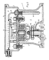
- a fuel pump having a flow meter of conventional type, in which a measuring apparatus 1 according to the invention can advantageously be used.
- the flow meter has two cylinders or measuring chambers 50, 51 whose axes make an angle of 120° to each other. In these cylinders, pistons 52 and 53 are acting. Liquid enters through an inlet 54 and flows upwards into a valve chamber 2 (Fig. 3).
- a crankcase 55 forms a third measuring chamber utilizing the combined movement of the two pistons 52, 53.
- a valve 56 (Fig.
- a channel 60 in the valve 56 has its openings at a spacing of 180°.
- cylinder and crankcase openings 61 are provided with a spacing of 120°.
- covers 63, 64 each defining a connecting duct 65 opening into the cylinder opening 61.
- a cover 66 having sealing O-rings is provided on the crankcase 55.
- the pistons 52, 53 are of the double-acting type with opposed cup leathers or seals 67, 68.
- the pistons are connected to a yoke assembly 69 guided in a rectilinear movement by a guide pin 70 and a guide bore 71 in the wall of the crankcase 55.
- the yoke 69 has a transverse slot 72 in which the outer ring of a ball bearing 73 is movable back and forth.
- the inner ring of the ball bearing 73 is fixed to a crankpin 74.
- the crankpin 74 is rigidly connected to a crank 75 which in turn is rigidly connected to the crankshaft 7.
- the liquid leaves the cylinders 50, 51 or the crankcase 55 through the channel 60 in the valve 56 and an outlet 62. This arrangement bears substantial resemblance to the device of DE-A-2,926,451 and is previously known.
- FIG. 3 there is shown an example of the measuring apparatus 1 according to the present invention.
- This measuring apparatus comprises the above-mentioned valve chamber 2 and a space 3 for measuring equipment.
- the valve chamber 2 and the space 3 are defined by side walls 4 and separated by a wall 5.
- the space 3 is further delimited at the top by a cover 6.
- the upper end of the crankshaft 7 is mounted by means of a ball bearing 76.
- the rotation of the crankshaft 7 is a function of the volume of liquid flowing through the valve chamber 2.
- the crankshaft 7 has a holder 8 carrying an annular permanent magnet 9.
- a second shaft 77 is rotatably mounted in the space 3 in a depressed portion 10 of the partition 5.
- the second shaft 77 carries, like the holder 8, an annular permanent magnet 11 concentric with the magnet 9.
- the rotation of the shaft assembly 7, 77 is detected by pulse generator means which comprise an apertured disk 12 mounted on the top end of the shaft 77, an optical transmitter 78 and an optical receiver 79.
- the pulse generator means are used for determining both the degree of rotation and the direction of rotation of the shaft 77.
- the optical receiver 79 is connected by a line 13 to a computing unit 14 which in turn is connected by a line 15 to a temperature sensor 16 disposed in the valve chamber 2 and by lines (not shown) to units arranged outside the measuring apparatus, such as a display unit and a central computer, which are of conventional type and therefore not described in more detail here.
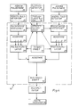
- Fig. 4 schematically shows the design of an embodiment of the measuring system according to the invention.
- This system can be used for determining the volume of the liquid flowing through the measuring apparatus during a measuring period.
- the measuring system has a first pulse generator 20 which may consist of the disk 12, the transmitter 78 and the receiver 79 and which is adapted to emit a predetermined number of pulses for each revolution the shaft assembly 7, 77 rotates in a first direction which, for example, is equal to the direction in which the shaft assembly normally rotates when dispensing petrol from a petrol storage tank at a filling station to the fuel tank of a vehicle.
- the pulse generator 20 is connected to a first pulse detector 21 adapted to detect the pulses emitted by the first pulse generator 20.
- a second pulse generator 22 adapted to emit the same predetermined number of pulses for each revolution the shaft assembly 7, 77 rotates in a second direction.
- This second direction is equal to the direction in which the shaft assembly rotates when liquid flows back through the measuring apparatus into the petrol storage tank.
- the second pulse generator 22 is connected to a second pulse detector 23 adapted to detect the pulses emitted by the second pulse generator 22.
- the first and the second pulse generator 20 and 22, respectively consist of a single generator by means of which the direction of rotation is detected in a suitable manner. For greater clarity, this single generator is shown as two separate blocks.
- the two pulse detectors 21 and 23 are each connected to an input of the computing unit 14.
- Each input of the computing unit is connected to a pulse-correcting computing unit 24 and 25, respectively, hereinafter referred to as "correcting unit".
- the output of this unit is connected to an adder unit 26 and 27, respectively.
- Each adder unit is in turn connected to a pulse accumulator 28 and 29, respectively.
- the outputs of the pulse accumulators 28 and 29 are connected to the positive input and the negative input, respectively, of an adder unit 30.
- the output of the adder unit 30 is connected to a scaling unit 32, i.e. a unit which rescales signals received.
- the computing unit 14 further has a time base unit 33 having an output connected to each pulse accumulator 28 and 29, and an output connected to a correction factor memory 34.
- This memory contains different correction factors used in the volume calculation and is connected to the two correcting units 24 and 25.
- the pulse accumulators 28, 29 are connected to the memory 34 for a purpose which will be discussed in more detail below.
- the output of the computing unit is connected to the input of a counter, a computer or similar unit, represented in Fig. 2 by a multiplier 35. In the multiplier 35, conversion of pulse number into volume is effected.
- the output of the multiplier 35 is connected to a display or other volume indicator 36 for presenting the measuring results.
- an aging detector 37 and a temperature detector 16 are also connected to the correction factor memory 34.
- the first pulse generator 20 thus generates a predetermined number of pulses for each revolution of the shaft assembly 7, 77. These pulses are detected by the first pulse detector 21 and supplied to the input of the computing unit 14. In the correcting unit 24, each pulse is corrected or "multiplied" by one or more correction factors retrieved from the memory 34. As earlier mentioned, the size of the measuring error varies with the flow rate of the liquid. In other words, one revolution of the shaft assembly 7, 77 does not correspond exactly to the same volume at all different flow rates. Therefore, flow rate correction is always carried out in the correcting unit 24.
- the memory 34 stores a list which contains the correction factors corresponding to different flow rates and all having a value close to 1. Preferably, there is one correction factor for each flow rate in liter per minute. This list of correction factors is established by accurate measurement and testing of a large number of flow meters of the type employed.
- the measuring period during which the liquid volume flowing through the measuring apparatus is measured is divided into a large number of measuring intervals of very short duration, for instance 50 ms, the duration of the measuring intervals being established by means of the time base unit 33.
- the flow rate can be assumed to be approximately constant.
- the flow rate will also vary but to a very small extent between two consecutive measuring intervals. During each separate measuring interval, the same correction factor can therefore be used for all pulses which are detected during that interval.
- the suitable correction factor for a specific measuring interval is determined by summing up the corrected pulse values for the pulses detected during a preceding measuring interval, thus giving a value of the flow rate which is used for retrieving the corresponding correction factor in the list stored in the memory 34. This summation takes place in the pulse accumulators 28, 29 which therefore are connected to the correction factor memory 34.
- corrections can also be effected in a similar manner in the correcting unit 24.
- Such corrections may include a correction for the temperature of the liquid, in which case the temperature is measured by the detector 16 and a correction factor corresponding to the temperature is retrieved from a list stored in the memory 34.
- Another such correction may be correction for aging of the measuring means. In this latter case, use is made of a correction factor the magnitude of which is a function of the total liquid volume measured by the measuring apparatus and which is established experimentally by aging tests on the measuring apparatus concerned.
- Each corrected pulse value is supplied from the correcting unit 24 to the adder unit 26 in which it is added to a first intermediate storage variable. Then, the integer part of the value of the first intermediate storage variable is obtained. This integer part is subtracted from the first intermediate storage variable and supplied to the pulse accumulator 28 in which it is added to a first summation variable. Since the pulse values (like the correction factors) are approximately equal to 1 and since these operations are effected for each pulse value supplied to the adder unit, the integer part always becomes equal to 2, 1 or 0, which is schematically shown in the Figure. In the pulse accumulator 28, the integer parts from the adder unit 26 are summed up during each measuring interval.
- Pulses generated by the second pulse generator 22 are processed in a similar manner.
- the pulses are detected by the second pulse detector 23 supplying them to the pulse-correcting computing unit 25 in which each pulse is corrected or multiplied by the same correction factor, retrieved from the memory 34, as used in the correcting unit 24 for the same measuring interval.
- Each corrected pulse value is supplied to the adder unit 27 and added therein to a second intermediate storage variable.
- the integer part of the value of the second intermediate storage variable is thereafter obtained. This integer part is subtracted from the second intermediate storage variable and added to a second summation variable in the pulse accumulator 29.
- the second summation variable is supplied back to the memory 34 to enable the suitable correction factor for the immediately following measuring interval to be supplied from the memory 34 to the correcting unit 25.
- the pulse sums accumulated in the pulse accumulators 28 and 29 during each measuring interval are supplied upon activation by a signal from the time base unit 33 to the positive and the negative input, respectively, of the adder unit 30.
- the net number of pulses for the measuring interval is then obtained.
- This net number is added to a third summation variable in a scaling unit 32, and the value of the third summation variable is integer-divided by a scale factor.
- a scale factor may for instance be equal to 10.
- Scaling is effected in order to make the measuring apparatus less sensitive to disturbance. By the scaling, occasional incorrect pulses will not have any major effect since, for example in the above-mentioned case using scale factor 10, at least 10 pulses are required for having a pulse supplied from the computing unit 14 to the equipment connected thereafter, in this case the multiplier 35.
- the remainder from the integer division in the scaling unit 32 is stored in the third summation variable while the result of the integer division is output from the computing unit 14 to be supplied to the multiplier 35 in which the number of pulses determined during each measuring interval is multiplied by a volume conversion factor.
- Fig. 5 shows an example of good correction obtainable electronically by means of the invention.
- the curves have been measured with an equipment of the type shown in Figs. l-4, with and without electronic correction. The measurements were carried out at varying flow rates in the range of 2-75 l/min. Without electronic correction according to the invention, the dashed error curve was obtained, from which it appears that the volume errors are greatest at low and high flow rates and that measuring errors also occur at normal flow rates of 25-40 l/min, used when supplying fuel to fuel tanks.
- the error curve indicated by a full line was obtained. When comparing the two curves, it can be seen that the error was reduced by half or more at high and low flow rates.
Abstract
Description
- The present invention relates to a method for measuring the volume of a liquid flowing through a measuring chamber during a measuring period, during which a number of pulses corresponding to the volume is generated by a pulse generator, which method comprises the steps of dividing the measuring period into a number of measuring intervals, detecting the pulses during each measuring interval, and multiplying the detected pulses by a flow correction factor. The invention also relates to an apparatus for carrying out this method.
- Methods and apparatus of this type are often used in connection with fuel pumps. For measuring the fuel volume, these pumps most often have movable pistons which are disposed in the measuring chamber and arranged to be displaced by the liquid the volume of which should be measured, and connected to a rotary shaft assembly driving said pulse generator. Such an apparatus is disclosed in DE-A-2,926,451.
- The measuring apparatus disclosed in DE-A-2,926,451 is intended for a fuel pump and comprises movable pistons disposed in the measuring chamber and displaced by the action of the liquid. The movement of the pistons is transmitted to a crankshaft the rotation of which is a function of the volume of the liquid flowing through the measuring chamber. The crankshaft extends through the wall of the measuring chamber and its end located outside the measuring chamber is connected to a pulse generator which comprises an apertured disk, an optical transmitter and an optical receiver, and emits a predetermined number of pulses for each revolution the crankshaft rotates. If the volume corresponding to one revolution of the crankshaft is known, i.e. the proportionality factor between the number of pulses and the volume, it is possible to measure the volume of the liquid which flows through the measuring chamber during a measuring period, by counting the number of pulses emitted by the pulse generator during the measuring period and multiplying this number by the proportionality factor. Since the pulses from the measuring apparatus described above are generally supplied directly to a volume counter, it is convenient that the same number of pulses always corresponds to the same volume irrespective of the measuring apparatus, such that the same factor for converting pulse number to volume can be used in all counters irrespective of what measuring apparatus they are connected to. However, for constructional reasons and depending on the liquid for which the measuring apparatus is used, the proportionality factor in practice varies for different measuring apparatus. As shown in the above-mentioned DE-A-2,926,451, this problem can however be solved by means of a correcting unit which is disposed after the pulse generator and in which the number of pulses counted is multiplied by a set correction factor, such that the desired pulse-to-volume ratio is obtained. Another known way of solving the contemplated problems is setting the stroke length of the pistons such that one revolution of the shaft corresponds to the desired volume. In a known measuring apparatus sold by the applicant, this is carried out manually with the aid of an eccentric assembly.
- The above-described apparatus and measuring methods however suffer from other problems and shortcomings to which no satisfactory solution has yet been found.
- One constructional drawback inherent in the apparatus described above relates to the calibration of the measuring apparatus in order to obtain the desired ratio of pulse number to volume. The eccentric assembly in the desired is complicated and comprises many parts, which means that the mounting operation becomes time-consuming and maintenance extensive. Further, both apparatus require manual calibration when the ratio of pulse number to volume changes as a result of aging and wear. A further drawback is that the apparatus are not sufficiently tamper-proof.
- Other problems and drawbacks relate to the measuring accuracy. It is of course desirable to obtain maximum measuring accuracy and e.g. in metering apparatus in petrol pumps, limits are set for the maximum permissible measuring error. Although present-day measuring apparatus have acceptable measuring accuracy, the size of the measuring error depends on the flow rate of the liquid, such that the measuring error becomes considerably larger at very small and at very high flow rates than at intermediate flow rates, which is by no means satisfactory. Further, according as the apparatus ages and is worn, the measuring error increases, meaning that the apparatus, as mentioned above, must be recalibrated.
- EP-A-0,011,787 describes a known construction for correcting flow rate-dependent measuring errors in a measuring apparatus comprising an impeller or turbine wheel rotating in a liquid flow and driving a pulse generator. The problem to be solved by means of this known device resides in the fact that the rotation of the turbine wheel is not strictly proportional to the passing liquid volume, especially at small flows. In one of the embodiments described (Fig. 10), use is made of a
measuring circuit 66 dividing the measuring period into a number of part measuring periods, e.g. of a duration of 6 sec. The measuring circuit has acounter 70 which during each part measuring period counts the number of pulses supplied from the turbine wheel. The number of pulses which is counted during one part measuring period and is a measurement of the flow rate during this part measuring period is supplied as a signal MS to amemory 62 storing some type of correction values as a function of the number of pulses. The value read from thememory 62 is multiplied by the signal MS in a multiplier 100 and added in an adder 64 to the sum of the corrected volume values determined for the preceding part measuring periods. The new sum is thereafter supplied to aregister 65 and thereafter to an indicator. EP-A-0,011,787 thus teaches the correction of volume measuring values for errors which are dependent on the flow rate, this correction being carried out on the basis of correction factors which are dependent on the flow rate and stored in a memory. Even if this correction is an improvement over the prior art technique, it is not sufficient in view of the stringent requirements set within e.g. the fuel distribution field. Moreover, the equipment is such that it necessitates modifications in that part of the existing equipments which indicates the measured values. - Other known apparatus and methods are described in DE-B-1,966,331, DE-A-2,850,671, DE-A-2,926,451, DE-A-3,010,263, EP-A-0,100,844, GB-A-1,482,279, GB-A-1,501,877, US-A-3,945,253 and US-A-3,965,341. These known apparatus and methods suffer from one or more of the above-mentioned drawbacks and do not give sufficiently accurate and corrected measuring values with regard to current requirements in e.g. in the fuel distribution field.
- Another drawback of the known measuring apparatus is that they do not take into account the temperature of the measured liquid. As is well known, the volume of liquids is temperature-dependent, which means that, e.g. when filling up a petrol tank, less energy per unit of volume is had the higher the temperature of the petrol is. Thus, it would be more reasonable if the petrol was paid for on the basis of the energy content instead of the volume. To this end, it is desirable to provide a measuring apparatus which can also determine the volume corresponding to a predetermined standard temperature.
- One object of the present invention is to provide a new method and a new apparatus for eliminating or considerably reducing one or more of the shortcomings inherent in known methods and apparatus. Thus, one object of the invention is to increase the measuring accuracy. Another preferred object is to provide an nstantaneous correction of the measuring values to permit installing the invention in existing measuring equipments without the need to modify the existing indicating equipment and other equipment connected thereafter. A further, preferred object is to permit correcting the volume measuring values with regard to temperature variations of the measured volume of liquid flow. Yet another preferred embodiment is to permit making corrections with regard to aging and wear of the volume measuring parts of the measuring equipment.
- The invention therefore provides a method of the type stated in the introduction to this specification, which is characterized by the steps, during each measuring interval, of detecting the pulses from the pulse generator, multiplying each separate detected pulse by a flow correction factor, determining this flow correction factor on the basis of the sum of the corrected pulse values for one or more of the preceding measuring intervals, adding the corrected pulse values to a summation variable and multiplying the value of this summation variable by a volume conversion factor for determining the liquid volume during the measuring interval concerned, and by the step of summing up the liquid volumes for all measuring intervals during said measuring period.
- In a preferred further development of the invention, an almost instantaneous correction of the measuring values obtained is achieved in that the step of adding the corrected pulse values to the summation variable is carried out by adding each corrected pulse value to an intermediate storage variable, by determining the integer part of the value of the intermediate storage variable, by subtracting this integer part from said intermediate storage variable and by adding this integer part to said summation variable.
- To permit measuring a liquid flow in both directions through the measuring equipment, it is preferred according to another embodiment of the invention to carry out the measurement by means of two pulse generators emitting a number of pulses corresponding to the volume when the liquid is flowing in one or the other direction through the measuring chamber, this embodiment comprising the steps, during each separate measuring interval, of detecting the pulses from the first and the second pulse generator, multiplying each separate detected pulse by the flow correction factor, adding the corrected pulse values of the first pulse generator to a first summation variable, adding the corrected pulse values of the second pulse generator to a second summation variable, and subtracting the second summation variable from the first summation variable before the step of multiplying the value of this summation variable by the volume conversion factor. In this embodiment of the invention, it is also preferred to carry out the step of adding the corrected pulse values to the second summation variable by adding each corrected pulse value to a second intermediate storage variable, by determining the integer part of the value of the second intermediate storage variable, by subtracting said integer part from said second intermediate storage variable and by adding this integer part to said second summation variable.
- When carrying out the method according to the invention, it is preferred to select the flow correction factor within the range of 0.0000-2.0000.
- In order to further increase the instantaneous measuring accuracy, the method according to a preferred further development of the invention comprises the steps, during each measuring interval, of integer-dividing the value of the summation variable by a first scale factor if the value of the summation variable is above 0, and by a second scale factor if the value of the summation variable is below 0, setting said summation variable equal to the remainder of the integer division, and multiplying the result of the integer division by the volume conversion factor for determining the liquid volume.
- To achieve the above-mentioned object of temperature correction of the measuring values, the method according to a preferred further development of the invention comprises the steps, during each measuring interval, of correcting each detected pulse by a temperature correction factor and determining this temperature correction factor on the basis of the temperature determined during the preceding measuring interval.
- To achieve the above-mentioned object of aging correction of the measuring values, the method according to a preferred further development of the invention comprises the steps, during each measuring interval, of correcting each detected pulse by an aging correction factor and determining this aging correction factor on the basis of the total liquid volume that has flown through the measuring chamber.
- As stated above, the invention also relates to an apparatus for measuring the volume of a liquid flowing through a measuring chamber during a measuring period. This apparatus has a pulse generator for emitting a number of pulses corresponding to the volume; detector means for detecting the pulses emitted by the pulse generator; time base means for dividing the measuring period into measuring intervals, the apparatus being characterized according to the invention by memory means for storing one or more correction factors determined on the basis of the sum of corrected pulse values from one or more of the preceding measuring intervals; multiplier means for multiplying each pulse detected by said detector means by said one or more correction factors; adder means for adding the corrected pulse values, and multiplier means for multiplying the sum of the added corrected pulse values by a volume conversion factor.
- In the preferred embodiments of the invention, the measuring accuracy is enhanced, the need for manual recalibration because of wear is reduced or eliminated, and it becomes possible to charge the consumer on the basis of the energy content and not the temperature-dependent volume. Also, the apparatus becomes more tamper-proof.
- The invention is primarily intended to be used in metering devices in filling stations and used for measuring the volume of fuel dispensed, but it may also be used for measuring larger volumes, for instance the volume of fuel supplied from a petrol truck to a tank or from a petrol store to a petrol truck.
- The invention will now be described in more detail hereinbelow with reference to the accompanying drawings which show preferred embodiments of the invention and in which:
- Fig. 1 is a part sectional view of one example of a fuel meter in which the inventive concepts can advantageously be applied
- Fig. 2 schematically shows a section taken along the line II-II in Fig. 1
- Fig. 3 schematically shows on a larger scale a part of the fuel meter in Figs. 1 and 2, supplemented with details included in an embodiment of the apparatus according to the invention;
- Fig. 4 is a block diagram schematically showing the principles of measurement according to an embodiment of the present invention
- Fig. 5 is a diagram illustrating the dependence of the volume measurement error on the flow rate before and after electronic correction of the measuring values in an embodiment using the method according to the invention.
- In Figs. 1 and 2, there is schematically shown a fuel pump having a flow meter of conventional type, in which a
measuring apparatus 1 according to the invention can advantageously be used. The flow meter has two cylinders or measuringchambers pistons 52 and 53 are acting. Liquid enters through aninlet 54 and flows upwards into a valve chamber 2 (Fig. 3). Acrankcase 55 forms a third measuring chamber utilizing the combined movement of the twopistons 52, 53. A valve 56 (Fig. 3) is held in contact with agraphite seal 57 by aspring 58 and by the pressure exerted by the surrounding liquid and is driven (rotated) by apin 59 rigidly connected to and projecting from acrankshaft 7. Achannel 60 in thevalve 56 has its openings at a spacing of 180°. In the valve seat, i.e. thegraphite seal 57, cylinder andcrankcase openings 61 are provided with a spacing of 120°. At the ends of thecylinders covers 63, 64 each defining a connectingduct 65 opening into thecylinder opening 61. Acover 66 having sealing O-rings is provided on thecrankcase 55. - The
pistons 52, 53 are of the double-acting type with opposed cup leathers or seals 67, 68. The pistons are connected to ayoke assembly 69 guided in a rectilinear movement by aguide pin 70 and a guide bore 71 in the wall of thecrankcase 55. Theyoke 69 has atransverse slot 72 in which the outer ring of aball bearing 73 is movable back and forth. The inner ring of theball bearing 73 is fixed to acrankpin 74. Thecrankpin 74 is rigidly connected to a crank 75 which in turn is rigidly connected to thecrankshaft 7. The liquid leaves thecylinders crankcase 55 through thechannel 60 in thevalve 56 and anoutlet 62. This arrangement bears substantial resemblance to the device of DE-A-2,926,451 and is previously known. - In Fig. 3, there is shown an example of the measuring
apparatus 1 according to the present invention. This measuring apparatus comprises the above-mentionedvalve chamber 2 and aspace 3 for measuring equipment. Thevalve chamber 2 and thespace 3 are defined byside walls 4 and separated by awall 5. Thespace 3 is further delimited at the top by a cover 6. In thevalve chamber 2, the upper end of thecrankshaft 7 is mounted by means of aball bearing 76. The rotation of thecrankshaft 7 is a function of the volume of liquid flowing through thevalve chamber 2. Thecrankshaft 7 has a holder 8 carrying an annularpermanent magnet 9. Asecond shaft 77 is rotatably mounted in thespace 3 in adepressed portion 10 of thepartition 5. Thesecond shaft 77 carries, like the holder 8, an annularpermanent magnet 11 concentric with themagnet 9. The rotation of theshaft assembly apertured disk 12 mounted on the top end of theshaft 77, an optical transmitter 78 and anoptical receiver 79. The pulse generator means are used for determining both the degree of rotation and the direction of rotation of theshaft 77. Theoptical receiver 79 is connected by aline 13 to acomputing unit 14 which in turn is connected by aline 15 to atemperature sensor 16 disposed in thevalve chamber 2 and by lines (not shown) to units arranged outside the measuring apparatus, such as a display unit and a central computer, which are of conventional type and therefore not described in more detail here. - Fig. 4 schematically shows the design of an embodiment of the measuring system according to the invention. This system can be used for determining the volume of the liquid flowing through the measuring apparatus during a measuring period. The measuring system has a
first pulse generator 20 which may consist of thedisk 12, the transmitter 78 and thereceiver 79 and which is adapted to emit a predetermined number of pulses for each revolution theshaft assembly pulse generator 20 is connected to afirst pulse detector 21 adapted to detect the pulses emitted by thefirst pulse generator 20. Similarly, there is provided asecond pulse generator 22 adapted to emit the same predetermined number of pulses for each revolution theshaft assembly second pulse generator 22 is connected to asecond pulse detector 23 adapted to detect the pulses emitted by thesecond pulse generator 22. In practice, the first and thesecond pulse generator pulse detectors computing unit 14. Each input of the computing unit is connected to a pulse-correctingcomputing unit adder unit pulse accumulator pulse accumulators adder unit 30. The output of theadder unit 30 is connected to ascaling unit 32, i.e. a unit which rescales signals received. Thecomputing unit 14 further has atime base unit 33 having an output connected to eachpulse accumulator correction factor memory 34. This memory contains different correction factors used in the volume calculation and is connected to the two correctingunits memory 34 for a purpose which will be discussed in more detail below. The output of the computing unit is connected to the input of a counter, a computer or similar unit, represented in Fig. 2 by amultiplier 35. In themultiplier 35, conversion of pulse number into volume is effected. The output of themultiplier 35 is connected to a display orother volume indicator 36 for presenting the measuring results. - In preferred embodiments of the invention, an aging
detector 37 and atemperature detector 16 are also connected to thecorrection factor memory 34. - The function of the measuring system shown in Fig. 4 will now be described in more detail. The
first pulse generator 20 thus generates a predetermined number of pulses for each revolution of theshaft assembly first pulse detector 21 and supplied to the input of thecomputing unit 14. In the correctingunit 24, each pulse is corrected or "multiplied" by one or more correction factors retrieved from thememory 34. As earlier mentioned, the size of the measuring error varies with the flow rate of the liquid. In other words, one revolution of theshaft assembly unit 24. Thememory 34 stores a list which contains the correction factors corresponding to different flow rates and all having a value close to 1. Preferably, there is one correction factor for each flow rate in liter per minute. This list of correction factors is established by accurate measurement and testing of a large number of flow meters of the type employed. - To permit selecting a suitable correction factor for correcting a pulse in the correcting
unit 24, the measuring period during which the liquid volume flowing through the measuring apparatus is measured, is divided into a large number of measuring intervals of very short duration, forinstance 50 ms, the duration of the measuring intervals being established by means of thetime base unit 33. During this short measuring interval, the flow rate can be assumed to be approximately constant. By the short duration of the measuring intervals, the flow rate will also vary but to a very small extent between two consecutive measuring intervals. During each separate measuring interval, the same correction factor can therefore be used for all pulses which are detected during that interval. The suitable correction factor for a specific measuring interval is determined by summing up the corrected pulse values for the pulses detected during a preceding measuring interval, thus giving a value of the flow rate which is used for retrieving the corresponding correction factor in the list stored in thememory 34. This summation takes place in thepulse accumulators correction factor memory 34. - In addition to flow rate correction, other corrections can also be effected in a similar manner in the correcting
unit 24. Such corrections may include a correction for the temperature of the liquid, in which case the temperature is measured by thedetector 16 and a correction factor corresponding to the temperature is retrieved from a list stored in thememory 34. Another such correction may be correction for aging of the measuring means. In this latter case, use is made of a correction factor the magnitude of which is a function of the total liquid volume measured by the measuring apparatus and which is established experimentally by aging tests on the measuring apparatus concerned. - Each corrected pulse value is supplied from the correcting
unit 24 to theadder unit 26 in which it is added to a first intermediate storage variable. Then, the integer part of the value of the first intermediate storage variable is obtained. This integer part is subtracted from the first intermediate storage variable and supplied to thepulse accumulator 28 in which it is added to a first summation variable. Since the pulse values (like the correction factors) are approximately equal to 1 and since these operations are effected for each pulse value supplied to the adder unit, the integer part always becomes equal to 2, 1 or 0, which is schematically shown in the Figure. In thepulse accumulator 28, the integer parts from theadder unit 26 are summed up during each measuring interval. - Pulses generated by the
second pulse generator 22 are processed in a similar manner. The pulses are detected by thesecond pulse detector 23 supplying them to the pulse-correctingcomputing unit 25 in which each pulse is corrected or multiplied by the same correction factor, retrieved from thememory 34, as used in the correctingunit 24 for the same measuring interval. Each corrected pulse value is supplied to theadder unit 27 and added therein to a second intermediate storage variable. The integer part of the value of the second intermediate storage variable is thereafter obtained. This integer part is subtracted from the second intermediate storage variable and added to a second summation variable in thepulse accumulator 29. As earlier, the second summation variable is supplied back to thememory 34 to enable the suitable correction factor for the immediately following measuring interval to be supplied from thememory 34 to the correctingunit 25. - The pulse sums accumulated in the
pulse accumulators time base unit 33 to the positive and the negative input, respectively, of theadder unit 30. The net number of pulses for the measuring interval is then obtained. This net number is added to a third summation variable in ascaling unit 32, and the value of the third summation variable is integer-divided by a scale factor. Preferably, use is made of different scale factors if the net number of pulses exceeds or falls below 0, i.e. if the number of pulses in the first direction is larger or smaller than the number of pulses in the other direction. In the first case, the scale factor may for instance be equal to 10. Scaling is effected in order to make the measuring apparatus less sensitive to disturbance. By the scaling, occasional incorrect pulses will not have any major effect since, for example in the above-mentioned case usingscale factor 10, at least 10 pulses are required for having a pulse supplied from thecomputing unit 14 to the equipment connected thereafter, in this case themultiplier 35. The remainder from the integer division in thescaling unit 32 is stored in the third summation variable while the result of the integer division is output from thecomputing unit 14 to be supplied to themultiplier 35 in which the number of pulses determined during each measuring interval is multiplied by a volume conversion factor. - It should be pointed out that the flow correction factor for correcting the flow rate-dependent measuring error is determined experimentally.
- Further, it should be noted that the correcting, adder, pulse accumulating, scaling and multiplier units are electronic devices known to those skilled in the art and therefore not described in more detail here.
- Fig. 5 shows an example of good correction obtainable electronically by means of the invention. The curves have been measured with an equipment of the type shown in Figs. l-4, with and without electronic correction. The measurements were carried out at varying flow rates in the range of 2-75 l/min. Without electronic correction according to the invention, the dashed error curve was obtained, from which it appears that the volume errors are greatest at low and high flow rates and that measuring errors also occur at normal flow rates of 25-40 l/min, used when supplying fuel to fuel tanks. When electronic correction was carried out according to the invention using the same flow meter, the error curve indicated by a full line was obtained. When comparing the two curves, it can be seen that the error was reduced by half or more at high and low flow rates.
- As will have been appreciated from the above, the correction of the volume measurement values takes place almost instantaneously when using the invention. This means that the measuring accuracy can be increased to a considerable extent as compared with what is possible with prior art equipments in which flow rate-dependent correction is carried out. Since correction is also carried out internally in the
computing unit 14, several advantages are gained, e.g. that the possibilities of tampering with the measur ing equipments are reduced, that the following equipment need not necessarily be modified and that the measuring equipment becomes less sensitive to disturbance, such as sudden pressure surges in the liquid inlet and liquid outlet conduits.
Claims (9)
Priority Applications (1)
| Application Number | Priority Date | Filing Date | Title |
|---|---|---|---|
| AT88850138T ATE59473T1 (en) | 1987-04-24 | 1988-04-22 | METHOD AND DEVICE FOR MEASURING THE VOLUME OF A FLOWING LIQUID. |
Applications Claiming Priority (2)
| Application Number | Priority Date | Filing Date | Title |
|---|---|---|---|
| SE8701686A SE460929B (en) | 1987-04-24 | 1987-04-24 | SET AND DEVICE MEASURING THE VOLUME OF A VOLUME THAT FLOWS THROUGH A MEETING CHAMBER DURING A MEASURING PERIOD |
| SE8701686 | 1987-04-24 |
Publications (2)
| Publication Number | Publication Date |
|---|---|
| EP0288448A1 true EP0288448A1 (en) | 1988-10-26 |
| EP0288448B1 EP0288448B1 (en) | 1990-12-27 |
Family
ID=20368292
Family Applications (1)
| Application Number | Title | Priority Date | Filing Date |
|---|---|---|---|
| EP88850138A Expired - Lifetime EP0288448B1 (en) | 1987-04-24 | 1988-04-22 | Method and apparatus for measuring the volum of a flowing liquid |
Country Status (15)
| Country | Link |
|---|---|
| US (1) | US4969365A (en) |
| EP (1) | EP0288448B1 (en) |
| JP (1) | JPH03500446A (en) |
| AT (1) | ATE59473T1 (en) |
| AU (1) | AU600828B2 (en) |
| BR (1) | BR8806995A (en) |
| DE (1) | DE3861413D1 (en) |
| ES (1) | ES2020609B3 (en) |
| FI (1) | FI87607C (en) |
| GR (1) | GR3001666T3 (en) |
| MY (1) | MY102203A (en) |
| PT (1) | PT87323B (en) |
| SE (1) | SE460929B (en) |
| WO (1) | WO1988008518A1 (en) |
| ZA (1) | ZA882825B (en) |
Cited By (4)
| Publication number | Priority date | Publication date | Assignee | Title |
|---|---|---|---|---|
| FR2747777A1 (en) * | 1996-04-19 | 1997-10-24 | Applic Mecaniques Et Electr De | METHOD FOR DETECTING A DYSFUNCTION OF A WATER METER AND EVALUATING ITS DURATION, AND ITS DEVICE FOR CARRYING OUT SAID METHOD |
| WO1998010248A2 (en) * | 1996-09-02 | 1998-03-12 | Tankanlagen Salzkotten Gmbh | Method and device for measuring the volumetric flow of a fluid |
| EP1746070A1 (en) * | 2005-07-19 | 2007-01-24 | Scheidt & Bachmann Gesellschaft mit beschränkter Haftung | Method for measuring the dispensed volume of a liquid |
| DE102008039272A1 (en) | 2008-08-23 | 2010-02-25 | Staake, Thorsten, Dr. | Method for determining resource consumption |
Families Citing this family (15)
| Publication number | Priority date | Publication date | Assignee | Title |
|---|---|---|---|---|
| EP0416163B1 (en) * | 1989-09-08 | 1993-06-23 | Scheidt & Bachmann Gmbh | Apparatus for correcting errors due to the construction of a flow meter having movable partitions |
| DE69229295T2 (en) * | 1991-04-04 | 1999-09-30 | Matsushita Electric Ind Co Ltd | Device for measuring and regulating the flow |
| US5251149A (en) * | 1991-08-02 | 1993-10-05 | Great Plains Industries, Inc. | Electronic nutating disc flow meter |
| US5333498A (en) * | 1992-06-19 | 1994-08-02 | W. L. Walker Co., Inc. | Apparatus and method for measuring physical characteristics of a liquid |
| US5574229A (en) * | 1994-03-21 | 1996-11-12 | Contadores De Aqua De Zaragoza | Electronic water meter with corrections for flow rate |
| EP0758465A4 (en) * | 1994-04-29 | 1998-11-11 | Electronic Warfare Associates | Liquid registration and control system having networked functional modules |
| US5542458A (en) * | 1994-08-22 | 1996-08-06 | Gilbarco Inc. | Vapor recovery system for a fuel delivery system |
| US5542302A (en) * | 1995-01-24 | 1996-08-06 | Mcmillan Company | Turbine wheel flow measuring transducer |
| US5659300A (en) * | 1995-01-30 | 1997-08-19 | Innovatec Corporation | Meter for measuring volumetric consumption of a commodity |
| SE511179C2 (en) * | 1996-11-07 | 1999-08-16 | Dresser Wayne Ab | Device for volume determination |
| DE19703243A1 (en) * | 1997-01-29 | 1998-07-30 | Tokheim Corp | Device for volume measurement of flowing media and corresponding method |
| SE511135C2 (en) | 1997-04-30 | 1999-08-09 | Dresser Wayne Ab | Methods and apparatus for generating digital signal changes when determining the amount of fuel output from a fuel pump unit |
| US6880390B2 (en) * | 2001-11-07 | 2005-04-19 | Bell Sea Marine Systems | Fuel meter for outboard engines |
| US20070119859A1 (en) * | 2005-11-14 | 2007-05-31 | Dresser, Inc. | Fuel Dispenser Management |
| US7941289B2 (en) | 2007-12-21 | 2011-05-10 | Dresser, Inc. | Fuel dispenser calibration |
Citations (10)
| Publication number | Priority date | Publication date | Assignee | Title |
|---|---|---|---|---|
| DE1966331B2 (en) * | 1968-02-09 | 1975-05-15 | Halliburton Co., Duncan, Okla. (V.St.A.) | Method and device for measuring the flow rate of a flowing medium |
| US3945253A (en) * | 1974-03-28 | 1976-03-23 | Liu Frederick F | Apparatus and method for measuring fluid flow over a wide range of fluid flow conditions and viscosities |
| US3965341A (en) * | 1975-01-10 | 1976-06-22 | Electrac, Inc. | Flow rate computer |
| GB1482279A (en) * | 1973-11-09 | 1977-08-10 | Griverus T | Digital transducers for measuring |
| GB1501877A (en) * | 1974-09-06 | 1978-02-22 | Ferranti Ltd | Signal processing apparatus |
| DE2850671A1 (en) * | 1977-11-23 | 1979-05-31 | Bulten Kanthal Ab | METHOD AND DEVICE FOR FLOW MEASUREMENT |
| EP0011787A1 (en) * | 1978-11-17 | 1980-06-11 | Nec Corporation | Liquid meter comprising a circuit for reducing a detection error resulting from a variable flow rate |
| DE2926451A1 (en) * | 1979-06-30 | 1981-01-15 | Scheidt & Bachmann Gmbh | VOLUME METER WITH MOVABLE PARTITIONS |
| DE3010263A1 (en) * | 1980-03-18 | 1981-04-02 | Flaco-Geräte GmbH, 4830 Gütersloh | Automobile calibratable fuel flow measuring system - mechanically determines discharge viscosity valves for electrical conversion into offset pulses per litre, supplied to microprocessor |
| EP0100844A1 (en) * | 1982-06-21 | 1984-02-22 | Oval Engineering Co., Ltd. | Instrumental error compensation circuit for flow meter |
Family Cites Families (5)
| Publication number | Priority date | Publication date | Assignee | Title |
|---|---|---|---|---|
| US3802261A (en) * | 1968-02-09 | 1974-04-09 | Halliburton Co | Fluid flow metering method and system |
| US4056717A (en) * | 1976-10-27 | 1977-11-01 | The Singer Company | Temperature correction systems for a fluid flow meter |
| US4390956A (en) * | 1981-03-06 | 1983-06-28 | The Singer Company | Apparatus for correcting measured gas flow |
| JPS5834321A (en) * | 1981-08-25 | 1983-02-28 | Aichi Tokei Denki Co Ltd | Correcting device for dual rotor type volumetric flow meter |
| EP0132374B1 (en) * | 1983-07-20 | 1988-01-20 | Tokyo Tatsuno Company Limited | Device for measuring liquid flow volume with temperature compensating |
-
1987
- 1987-04-24 SE SE8701686A patent/SE460929B/en not_active IP Right Cessation
-
1988
- 1988-04-21 ZA ZA882825A patent/ZA882825B/en unknown
- 1988-04-22 DE DE8888850138T patent/DE3861413D1/en not_active Expired - Fee Related
- 1988-04-22 BR BR888806995A patent/BR8806995A/en unknown
- 1988-04-22 AU AU16859/88A patent/AU600828B2/en not_active Ceased
- 1988-04-22 AT AT88850138T patent/ATE59473T1/en not_active IP Right Cessation
- 1988-04-22 JP JP63503716A patent/JPH03500446A/en active Pending
- 1988-04-22 EP EP88850138A patent/EP0288448B1/en not_active Expired - Lifetime
- 1988-04-22 PT PT87323A patent/PT87323B/en not_active IP Right Cessation
- 1988-04-22 ES ES88850138T patent/ES2020609B3/en not_active Expired - Lifetime
- 1988-04-22 WO PCT/SE1988/000203 patent/WO1988008518A1/en active IP Right Grant
- 1988-04-23 MY MYPI88000424A patent/MY102203A/en unknown
- 1988-12-20 FI FI885890A patent/FI87607C/en not_active IP Right Cessation
-
1989
- 1989-12-04 US US07/449,509 patent/US4969365A/en not_active Expired - Fee Related
-
1991
- 1991-03-27 GR GR91400378T patent/GR3001666T3/en unknown
Patent Citations (10)
| Publication number | Priority date | Publication date | Assignee | Title |
|---|---|---|---|---|
| DE1966331B2 (en) * | 1968-02-09 | 1975-05-15 | Halliburton Co., Duncan, Okla. (V.St.A.) | Method and device for measuring the flow rate of a flowing medium |
| GB1482279A (en) * | 1973-11-09 | 1977-08-10 | Griverus T | Digital transducers for measuring |
| US3945253A (en) * | 1974-03-28 | 1976-03-23 | Liu Frederick F | Apparatus and method for measuring fluid flow over a wide range of fluid flow conditions and viscosities |
| GB1501877A (en) * | 1974-09-06 | 1978-02-22 | Ferranti Ltd | Signal processing apparatus |
| US3965341A (en) * | 1975-01-10 | 1976-06-22 | Electrac, Inc. | Flow rate computer |
| DE2850671A1 (en) * | 1977-11-23 | 1979-05-31 | Bulten Kanthal Ab | METHOD AND DEVICE FOR FLOW MEASUREMENT |
| EP0011787A1 (en) * | 1978-11-17 | 1980-06-11 | Nec Corporation | Liquid meter comprising a circuit for reducing a detection error resulting from a variable flow rate |
| DE2926451A1 (en) * | 1979-06-30 | 1981-01-15 | Scheidt & Bachmann Gmbh | VOLUME METER WITH MOVABLE PARTITIONS |
| DE3010263A1 (en) * | 1980-03-18 | 1981-04-02 | Flaco-Geräte GmbH, 4830 Gütersloh | Automobile calibratable fuel flow measuring system - mechanically determines discharge viscosity valves for electrical conversion into offset pulses per litre, supplied to microprocessor |
| EP0100844A1 (en) * | 1982-06-21 | 1984-02-22 | Oval Engineering Co., Ltd. | Instrumental error compensation circuit for flow meter |
Cited By (12)
| Publication number | Priority date | Publication date | Assignee | Title |
|---|---|---|---|---|
| FR2747777A1 (en) * | 1996-04-19 | 1997-10-24 | Applic Mecaniques Et Electr De | METHOD FOR DETECTING A DYSFUNCTION OF A WATER METER AND EVALUATING ITS DURATION, AND ITS DEVICE FOR CARRYING OUT SAID METHOD |
| WO1997040351A1 (en) * | 1996-04-19 | 1997-10-30 | Societe Anonyme De Production De Procedes De Comptage De L'eau Et Autres Liquides, Sappel | Method for detecting water meter malfunction, calculating the duration thereof, and device for implementing same |
| US6082169A (en) * | 1996-04-19 | 2000-07-04 | Societe Anonyme De Production De Procedes De Comptage De L'eau Et Autres Liquides, Sappel | Method for detecting water meter malfunction, calculating the duration thereof, and device for implementing same |
| WO1998010248A2 (en) * | 1996-09-02 | 1998-03-12 | Tankanlagen Salzkotten Gmbh | Method and device for measuring the volumetric flow of a fluid |
| WO1998010248A3 (en) * | 1996-09-02 | 1998-04-30 | Salzkotten Tankanlagen | Method and device for measuring the volumetric flow of a fluid |
| AU722288B2 (en) * | 1996-09-02 | 2000-07-27 | Marconi Commerce Systems Gmbh & Co. Kg | Method and device for measuring the volumetric flow of a fluid |
| US6721669B2 (en) | 1996-09-02 | 2004-04-13 | Gilbarco Inc. | Method and device for measuring the volumetric flow of a fluid |
| EP1746070A1 (en) * | 2005-07-19 | 2007-01-24 | Scheidt & Bachmann Gesellschaft mit beschränkter Haftung | Method for measuring the dispensed volume of a liquid |
| DE102008039272A1 (en) | 2008-08-23 | 2010-02-25 | Staake, Thorsten, Dr. | Method for determining resource consumption |
| WO2010026071A1 (en) | 2008-08-23 | 2010-03-11 | Amphiro Ag | Method and apparatus for determining resource consumption |
| DE102008064677A1 (en) | 2008-08-23 | 2010-12-02 | Amphiro Ag | Method and arrangement for determining the consumption of resources |
| DE102008039272B4 (en) | 2008-08-23 | 2021-08-26 | Amphiro Ag | Procedure for determining resource consumption |
Also Published As
| Publication number | Publication date |
|---|---|
| ZA882825B (en) | 1989-02-22 |
| AU1685988A (en) | 1988-12-02 |
| PT87323B (en) | 1993-09-30 |
| FI87607C (en) | 1993-01-25 |
| ES2020609B3 (en) | 1991-08-16 |
| DE3861413D1 (en) | 1991-02-07 |
| MY102203A (en) | 1992-04-30 |
| AU600828B2 (en) | 1990-08-23 |
| GR3001666T3 (en) | 1992-11-23 |
| US4969365A (en) | 1990-11-13 |
| SE8701686L (en) | 1988-10-25 |
| SE460929B (en) | 1989-12-04 |
| ATE59473T1 (en) | 1991-01-15 |
| FI885890A (en) | 1988-12-20 |
| BR8806995A (en) | 1989-10-31 |
| WO1988008518A1 (en) | 1988-11-03 |
| PT87323A (en) | 1989-05-12 |
| JPH03500446A (en) | 1991-01-31 |
| FI87607B (en) | 1992-10-15 |
| EP0288448B1 (en) | 1990-12-27 |
| SE8701686D0 (en) | 1987-04-24 |
Similar Documents
| Publication | Publication Date | Title |
|---|---|---|
| US4969365A (en) | Method and apparatus for measuring the volume of a flowing liquid | |
| US5447062A (en) | Apparatus for measuring quantities of liquid in gasoline pumps of motor vehicle filling stations | |
| US5056017A (en) | System to monitor fuel level in a tank, and fuel dispensed from the tank, to determine fuel leakage and theft losses | |
| US6721669B2 (en) | Method and device for measuring the volumetric flow of a fluid | |
| US5050094A (en) | Compensating method and device for instrumental error in rotary displacement flowmeter | |
| US20180128662A1 (en) | Method and apparatus for determining the mass of a fluid flowing through a flow rate meter in a consumption time interval | |
| EP0619874B1 (en) | Apparatus for determining emptying characteristics | |
| EP0154531A1 (en) | Electronic square root error indicator | |
| US5471867A (en) | Inventory reconciliation for above ground storage tanks | |
| US6739205B2 (en) | Controller for monitoring fluid flow volume | |
| US3631709A (en) | High-speed calibration of liquid flow meters | |
| US4212195A (en) | System to measure fuel consumption of a vehicle | |
| EP0074164A1 (en) | Gas dispensing apparatus | |
| NO172365B (en) | PROCEDURE AND DEVICE FOR MEASURING THE VOLUME OF A FLOWING FLUID | |
| US20020128792A1 (en) | Method and device for measuring the volumetric flow of a fluid | |
| JP3291772B2 (en) | Appliance identification device | |
| WO2002001164A1 (en) | Flow meter for liquids | |
| JPH0642993A (en) | Flowrate measuring instrument | |
| RU1802298C (en) | Liquid mass meter | |
| JP3323088B2 (en) | Flowmeter | |
| WO1981003379A1 (en) | Device for measuring the amount flowing through and/or the speed of flow of a medium | |
| GB2267479A (en) | Liquid dispensing : metering accuracy | |
| HU193776B (en) | Electronic quantity meter for measuring the charge quantity of liquids of two kinds | |
| JPS604818A (en) | Flow rate measuring apparatus | |
| JPS6367130B2 (en) |
Legal Events
| Date | Code | Title | Description |
|---|---|---|---|
| PUAI | Public reference made under article 153(3) epc to a published international application that has entered the european phase |
Free format text: ORIGINAL CODE: 0009012 |
|
| AK | Designated contracting states |
Kind code of ref document: A1 Designated state(s): AT BE CH DE ES FR GB GR IT LI LU NL SE |
|
| 17P | Request for examination filed |
Effective date: 19880928 |
|
| 17Q | First examination report despatched |
Effective date: 19900216 |
|
| GRAA | (expected) grant |
Free format text: ORIGINAL CODE: 0009210 |
|
| AK | Designated contracting states |
Kind code of ref document: B1 Designated state(s): AT BE CH DE ES FR GB GR IT LI LU NL SE |
|
| PG25 | Lapsed in a contracting state [announced via postgrant information from national office to epo] |
Ref country code: SE Free format text: THE PATENT HAS BEEN ANNULLED BY A DECISION OF A NATIONAL AUTHORITY Effective date: 19901227 |
|
| REF | Corresponds to: |
Ref document number: 59473 Country of ref document: AT Date of ref document: 19910115 Kind code of ref document: T |
|
| REF | Corresponds to: |
Ref document number: 3861413 Country of ref document: DE Date of ref document: 19910207 |
|
| ITF | It: translation for a ep patent filed |
Owner name: NOTARBARTOLO & GERVASI S.R.L. |
|
| ET | Fr: translation filed | ||
| PLBE | No opposition filed within time limit |
Free format text: ORIGINAL CODE: 0009261 |
|
| STAA | Information on the status of an ep patent application or granted ep patent |
Free format text: STATUS: NO OPPOSITION FILED WITHIN TIME LIMIT |
|
| 26N | No opposition filed | ||
| PGFP | Annual fee paid to national office [announced via postgrant information from national office to epo] |
Ref country code: GB Payment date: 19920323 Year of fee payment: 5 |
|
| PGFP | Annual fee paid to national office [announced via postgrant information from national office to epo] |
Ref country code: LU Payment date: 19920414 Year of fee payment: 5 |
|
| PGFP | Annual fee paid to national office [announced via postgrant information from national office to epo] |
Ref country code: AT Payment date: 19920416 Year of fee payment: 5 |
|
| PGFP | Annual fee paid to national office [announced via postgrant information from national office to epo] |
Ref country code: GR Payment date: 19920422 Year of fee payment: 5 |
|
| PGFP | Annual fee paid to national office [announced via postgrant information from national office to epo] |
Ref country code: BE Payment date: 19920423 Year of fee payment: 5 |
|
| PGFP | Annual fee paid to national office [announced via postgrant information from national office to epo] |
Ref country code: FR Payment date: 19920424 Year of fee payment: 5 |
|
| PGFP | Annual fee paid to national office [announced via postgrant information from national office to epo] |
Ref country code: ES Payment date: 19920428 Year of fee payment: 5 |
|
| ITTA | It: last paid annual fee | ||
| PGFP | Annual fee paid to national office [announced via postgrant information from national office to epo] |
Ref country code: NL Payment date: 19920430 Year of fee payment: 5 |
|
| REG | Reference to a national code |
Ref country code: GR Ref legal event code: FG4A Free format text: 3001666 |
|
| EPTA | Lu: last paid annual fee | ||
| PG25 | Lapsed in a contracting state [announced via postgrant information from national office to epo] |
Ref country code: LU Free format text: LAPSE BECAUSE OF NON-PAYMENT OF DUE FEES Effective date: 19930422 Ref country code: GB Effective date: 19930422 Ref country code: AT Effective date: 19930422 |
|
| PG25 | Lapsed in a contracting state [announced via postgrant information from national office to epo] |
Ref country code: ES Free format text: LAPSE BECAUSE OF NON-PAYMENT OF DUE FEES Effective date: 19930423 |
|
| PGFP | Annual fee paid to national office [announced via postgrant information from national office to epo] |
Ref country code: CH Payment date: 19930426 Year of fee payment: 6 |
|
| PG25 | Lapsed in a contracting state [announced via postgrant information from national office to epo] |
Ref country code: BE Effective date: 19930430 |
|
| BERE | Be: lapsed |
Owner name: LJUNGMANS INDUSTRIER A.B. Effective date: 19930430 |
|
| PG25 | Lapsed in a contracting state [announced via postgrant information from national office to epo] |
Ref country code: GR Free format text: THE PATENT HAS BEEN ANNULLED BY A DECISION OF A NATIONAL AUTHORITY Effective date: 19931031 |
|
| PG25 | Lapsed in a contracting state [announced via postgrant information from national office to epo] |
Ref country code: NL Effective date: 19931101 |
|
| NLV4 | Nl: lapsed or anulled due to non-payment of the annual fee | ||
| GBPC | Gb: european patent ceased through non-payment of renewal fee |
Effective date: 19930422 |
|
| PG25 | Lapsed in a contracting state [announced via postgrant information from national office to epo] |
Ref country code: FR Effective date: 19931229 |
|
| REG | Reference to a national code |
Ref country code: FR Ref legal event code: ST |
|
| PG25 | Lapsed in a contracting state [announced via postgrant information from national office to epo] |
Ref country code: LI Effective date: 19940430 Ref country code: CH Effective date: 19940430 |
|
| REG | Reference to a national code |
Ref country code: CH Ref legal event code: PL Ref country code: GR Ref legal event code: MM2A Free format text: 3001666 |
|
| REG | Reference to a national code |
Ref country code: ES Ref legal event code: FD2A Effective date: 19990503 |
|
| PGFP | Annual fee paid to national office [announced via postgrant information from national office to epo] |
Ref country code: DE Payment date: 20010405 Year of fee payment: 14 |
|
| PG25 | Lapsed in a contracting state [announced via postgrant information from national office to epo] |
Ref country code: DE Free format text: LAPSE BECAUSE OF NON-PAYMENT OF DUE FEES Effective date: 20021101 |
|
| PG25 | Lapsed in a contracting state [announced via postgrant information from national office to epo] |
Ref country code: IT Free format text: LAPSE BECAUSE OF NON-PAYMENT OF DUE FEES Effective date: 20050422 |