I. Introduction and Basic Theory
-
This patent disclosure describes applications of the electrostatic voltage excitation process for: 1) Decontamination of radioactive waste at nuclear power sites and elsewhere; 2) The generation of nuclear power using alpha, beta and gamma emitting materials as fuel; 3) The generation of fusion power from low voltage deuteron-deuteron interaction in water; and 4) The production of precious metals like rhodium and platinum by accelerated alpha decay.
-
These advances in the field of nuclear chemistry became possible by the discovery that the rates of decay of alpha, beta and gamma emitters increase dramatically when they are energized with a high electrostatic voltage. An electrostatic generator such as a Van de Graaff generator, is suitable for carrying out this process. Its spherical or cylindrical terminal receives a charge from a moving, insulated belt or chain. The electrostatic field inside the cavity is zero by Gauss' theorum, while beyond the terminal surface a field exists. For a sphere the field is:
- E = Q/(47reo r2)t where "Q" is the surface charge on the sphere. The electrostatic potential is constant inside the sphere and on its surface, which is a key point. For a sphere the potential is: 0 = Q/(4πε0a) with "a" the sphere radius. Outside the sphere, the potential is (o = Q/(4πε0r), which goes to zero for large distances "r" from the sphere's center.
-
If the charge on the terminal is negative, the corresponding voltage ø inside the cavity and on its surface is negative. The second terminal on the generator is usually grounded, in which case the potential difference between the terminals is:
- △ø = -|Q|/(4πε0a). The potential energy of a charge q inside the cavity is qo. An alpha particle of charge 2e has a potential energy of -2|eø|. Only outside the cavity will the alpha particle be accelerated towards the negatively charged terminal surface.
-
Consider a radioactive alpha source located in an energized cavity or hollow body of Van de Graaf generator. The electrostatic voltage is constant throughout the cavity and the source material in the cavity. The potential energy of the Coulomb barrier resisting particle escape is lowered by 2|eø| from 2Ze2/r. The decay rate of the radioactive source material increases exponentially with the negative voltage. Electrostatic voltage excitation, therefore, modifies the Coulomb barrier of the material. The electrons in the atoms and the protons in the daughter nuclei of the source material are also excited but with a lesser effect.
-
Experimental documentation for this disclosure is provided by:
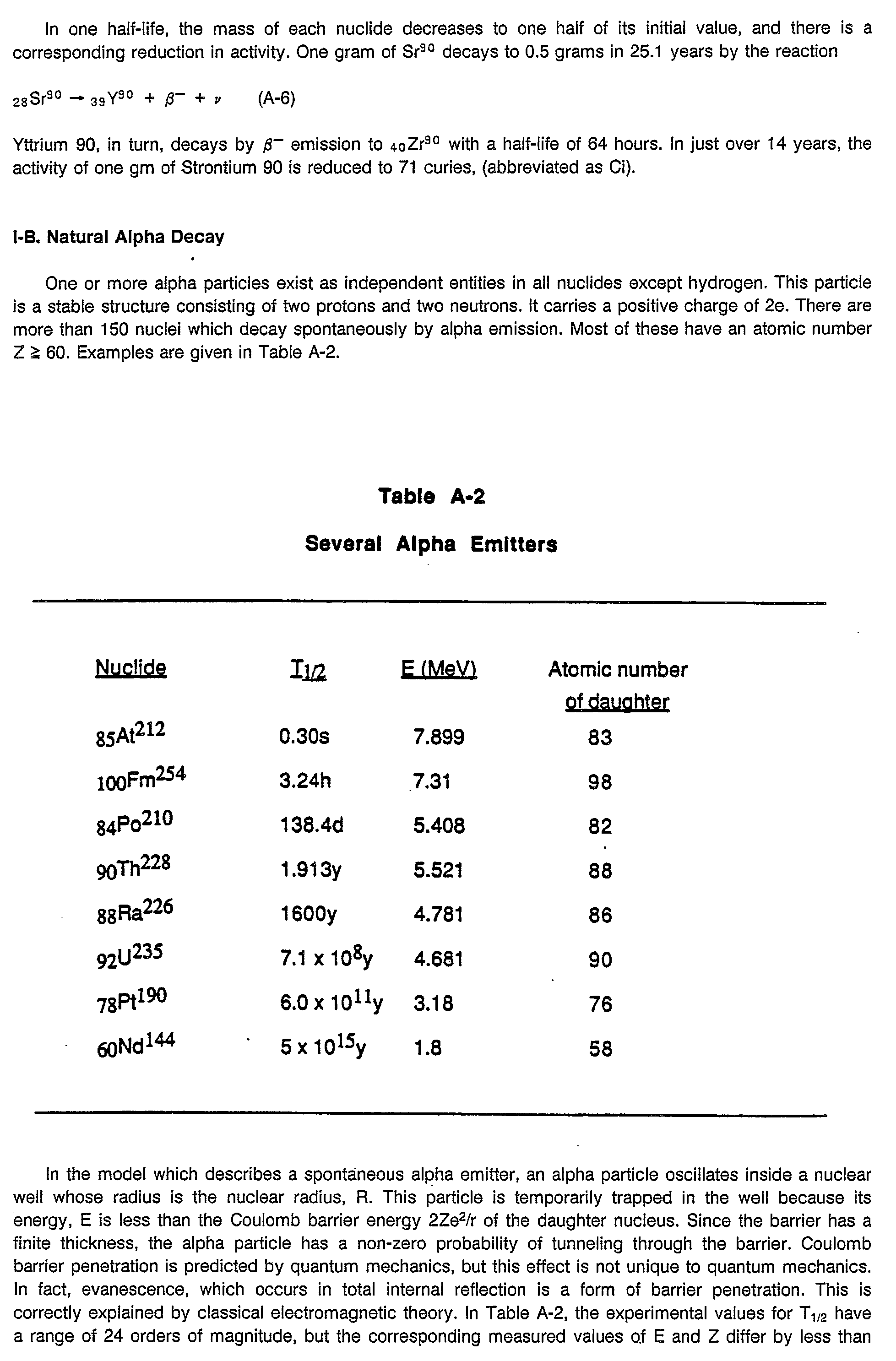
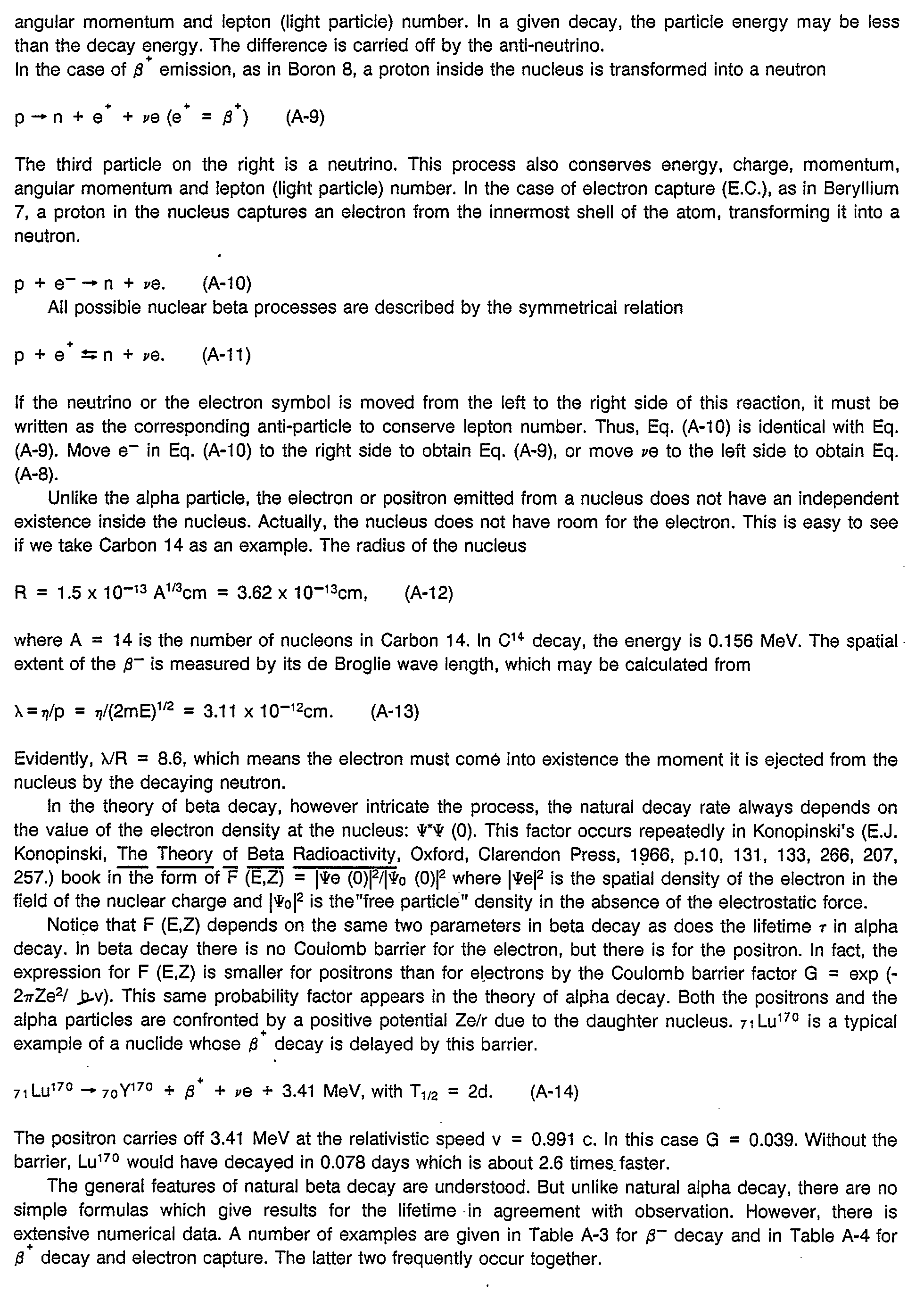
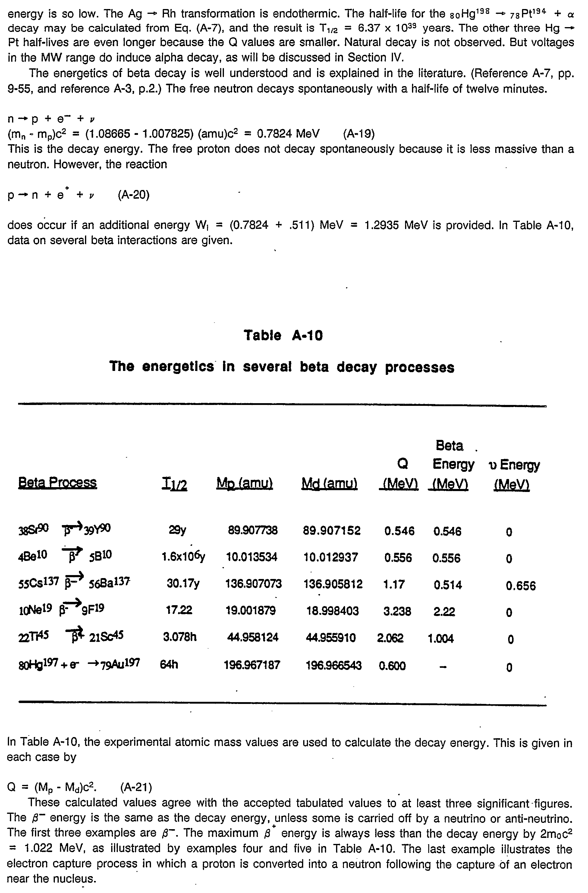
- a) A scientific summary of radioactive decay, nuclear stability, the energetics of decay processes, and fission. This material, presented in Appendix A, is well known in the scientific community and it provides a background for the current application.
- b) U.S. patent application, Serial No. 112,854, -filed October 23, 1987, incorporated herein by reference, describes how electrostatic voltage excitation can serve to decontaminate radioactive sources.
- c) A scientific manuscript entitled, Thorium 230 Decay by Coulomb Barrier Modification, Appendix B.
- d) A scientific manuscript entitled, The Theory of the Rapid Depletion of Alpha Decay by Electrostatic Voltage Excitation. Experimental verification for Thorium 230 and Polonium 210, Appendix C.
- e) A scientific manuscript entitled, The Theory of Accelerated Beta Decay by Electrostatic Voltage Excitation. Experimental verification for Thallium 204 and Lead 210 in Appendix D herein.
- f) A scientific manuscript entitled, The Fusion of Deuterons in Water by Electrostatic Voltage Excitation, Appendix E.
-
The primary object of the present invention is to provide apparatus and a method for using electrostatic voltage excitation to modify the Coulomb barrier of material, such as radioactive materials or water, to enhance alpha, beta and gamma decay from the materials or to provide for low voltage deuteron-deuteron fusion of water, whereby said materials can be decontaminated or be used for generating power as well as - for the transmutation of one metal of low value into another metal of high value.
-
Other objects of this invention will become apparent as the following specification progresses, reference being had to the accompanying drawings for an illustration of several embodiments of the apparatus of the invention.
IN THE DRAWINGS:
-
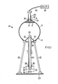
- Fig. 1 is a schematic view of an electrostatic generator of the present invention used to enhance alpha, beta, and gamma decay of radioactive materials with the counter sensor for detecting the particle decay being external to the hollow body of the generator;
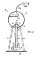
- Fig. 2 is a view similar to Fig. 1 but showing the particle counter sensor within the hollow body of the generator to permit high voltage operation of the generator;
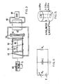
- Fig. 3 is a schematic view, partly in section of an electrostatic generator with a coolant coil surrounding the same for generating power as heat energy which is transferred to the coolant in the coil and into a heat exchanger for providing power to a load coupled to the generator;
- Fig. 4 is an equivalent circuit for controlling the deuteron-deuteron fusion process of the. present invention;
- Fig. 5 is a schematic view of the electrostatic generator used in the deuteron-deuteron fusion process;
- Fig. 6 is the electrostatic potential and field of the electrostatic generator as plotted as a function of distance r from the center of the hollow body of the generator at radius a carrying a surface charge Q;
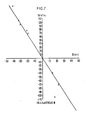
- Fig. 7 is a plot of In y/ -yoV. ¢;
- Fig. 8 is a modified potential barrier for an alpha particle;
- Fig. 9 is a plot of oscillatory delay of strontium 90; arid
- Fig. 10 is a plot of the unexcited and excited gamma decay spectrum of AM24-1.
II. Decontamination
-
The principal source of radioactive waste is at nuclear power plants, where the spent fuel rods are stored underwater. There are about 400 nuclear power plants in the world, of which 106 are located in the United States. There are definite plans for the construction of 225 more plants worldwide. The spent fuel rods, and other radioactive waste produced by this nation's operating fission burner reactors has been accumulating since 1945. The level of radioactive waste in the United States is now estimated to be anywhere from 9,000 to 40,000 metric tons. The worldwide radioactive waste from fission power plants may well be in excess of 100,000 metric tons.
-
There is widespread radioactive contamination in other locations.
- 1) Mill tailings: Long lived uranium and thorium debris left at the mill after the uranium has been exhausted from the parent rock.
- (2) Transuranic waste (atomic number greater than 92, like plutonium) produced in the nuclear weapons program.
- (3) Spent U235 rods used in U.S. submarines and other naval vessels, and spent fuel rods from the ships of the USSR and other nations.
- (4) Radioactive waste stored in saltmines and other geologic sites.
- (5) Extensive surface contamination of islands in the Pacific, used as testing grounds for the hydrogen bomb by the United States and France.
- (6) Underground contamination at H bomb test sites in Nevada and in the USSR.
- (7) Contaminated areas produced by accidents at nuclear power plants like Chernobyl.
- 8. Accidental spillage or loss of radioactive material in transit, at manufacturing sites, or in hospitals (as in Brazil).
-
In U.S. patent application Serial No. 112,854 filed October 23, 1987, several techniques for radioactive decontamination are described. The most effective method is by electrostatic voltage excitation where the contaminated material is placed inside an electrostatic generator (Van de Graaff), operating at voltages - 250 kV to 850 kV. The voltage on the surface of the generator terminal is constant throughout the terminal cavity, including all the atoms in the contaminated source. The electrostatic field inside the cavity is zero, which means that charged particles of the contaminated source are not accelerated until after they exit the cavity of the high voltage terminal:
- Inside the cavity, the potential energy of each particle of charge q is increased by an amount qϕ, where ϕ is the terminal voltage. If ø is negative, the potential energy of alpha particles is decreased by 2|eø|, whereas the potential energy of electrons is increased by |eø|. The Coulomb barrier of the alpha particle is lowered to 2Ze2/r- |eø|, resulting in accelerated decay. Many of the atomic electrons are ionized. This change in electron charge distribution increases beta decay.
-
There are other decontamination methods discussed in the above patent application. Prominent among these methods is laser excitation. Experiments show that electrostatic voltage excitation is more effective than laser excitation. This is especially the case when the contamination samples are large in comparison with spot size. Electrostatic voltage excitation should be used when there are large volumes of radioactive waste awaiting decontamination, as at nuclear power plants.
-
It should be emphasized that extensive evidence has been obtained to show decontamination by electrostatic voltage excitation. Laser excitation of radioactive sources does generate vibrations in the rate of counting of alpha particles, but it is not known whether or not accelerated decay takes place. Accelerated decay has been observed for all radioactive sources subjected to electrostatic voltage excitation in a Van de Graaff generator, (see Fig. 1 of U.S. patent application Serial No. 112,854), for a period of six hours or more. We define this as activity which is substantially different from the initial unexcited activity.
-
We have observed that two alpha sources and two beta sources decay to background in a time relatively short compared with their lifetimes. Typically, such a change is observed in the counting rate anywhere from six days to six weeks after excitation. The post-excitation reaction mode is a transient, with a relaxation time of the order of six weeks or more. The activity in counts per second undergoes oscillatory decay.
-
We have observed two alpha sources and one gamma source in the process of accelerated decay. Evidently, the voltages were not high enough to lead to total decay in several weeks. In the test apparatus used, the Van de Graaff voltage is limited by the relative humidity. If the relative humidity is 50% or higher, we cannot get sustained voltages above 200 KeV. This results in accelerated decay and partial decontamination. We have experimental evidence that alpha, beta and gamma decay are all accelerated by electrostatic voltage excitation. Technical details for the decontamination of alpha and beta emitters are given in Appendices B, C, and D.
-
Accelerated decay in the gamma decay of Am241 has been observed. The source we used was a closed 54.2 micro-curie alpha emitter. This source was embedded in a plastic cylinder six mm thick so that no alphas were detectable. The radiation which penetrates the cylinder is a discrete gamma spectrum consisting of nine gamma lines in the range from 11.871 to 59.5364 keV. Seven of these lines are associated with the excited states of neptunium, the alpha daughter of americium. The other two gammas are electric dipole transitions. The initial pre-excitation Am24' count on our Geiger counter was 595 cps. Four weeks after excitation, the count had risen to 734 cps, and then it rose rather quickly to 1490 cps and 2508 cps, 4.2 times the initial value. It later dropped to about 1576 cps, a reasonably steady value. This is a clear evidence of accelerated gamma decay.
-
The Am241 source was analyzed with an x-ray spectrometer at San Jose State University by Dr. Peter Englert, a radiation chemist. The numerical printout for the excited source was compared with an unexcited source.
-
The spectra differ as shown in Table A-2a as follows: 1) All of the NpL lines in the excited source are more intense than in the unexcited source, but the yEl line is less intense. 2) The total count for the excited source exceeded that of the unexcited source by a factor of 2.15- a value which is about the same as the GM ratio. 3) There is evidence of PaLa and PaL;8 in the excited spectrum. These are photons from Neptunium, the first alpha daughter of Americium (see Fig. 10).
-
Details are given in Table A-2a. These measurements and analysis suggest that AM 241 is undergoing accelerated alpha decay as reflected in the more intense NpL lines, the presence of the PaL lines, and in the higher overall gamma rate.
-
An electrostatic generator to illustrate the teachings of decontamination of the present invention is broadly denoted by the numeral 10 and is shown in Fig. 1. The purpose of the generator is to excite the electrons, protons, and alpha particles inside the atoms in radioactive materials, thereby increasing the counting rate or rate of decay of alpha, beta and gamma particles from the materials and thereby decontaminating the materials.
-
The decontamination is accomplished in the generator of Fig. 1 by the application of a stimulus in the form of a negative electrical potential on the surface and inside the generator including all the atoms is the radiactive material. As the negative electrostatic potential excites the charged particles inside the atoms, the counting rate or rate of emission of alpha, beta and gamma particles is increased to thereby accelerate particle decay and thereby the decontamination of the radioactive materials.
-
Generator 10 includes hollow body or sphere 13 forming part of a generator mechanism 14. A radioactive sample 15 to be enhanced or decontaminated is placed on a platform 16 supported by a bracket 17 on the interior of sphere 13 near the upper end thereof adjacent to hole 19 in the sphere. Thus, the radioactive sample is within the sphere and will be subjected to the electrostatic potential generated in the sphere as hereinafter described.
-
The sphere 13 is supported on legs 22 on a base 23 which is grounded. Thus the sphere 13 must be maintained in spatial and electrical isolation from all other elements including the base plate 23. To this end, legs 22 must be electrical insulators.
-
Sphere 13 receives electrical charges by way of an insulated moving belt 24 which extends between an interior pulley 26 within sphere 13 and an exterior pulley 28 carried in some suitable manner and on base 23. Drive mechanism 30 is a motor providing rotation of motion of exterior pulley 128.
-
A voltage generator is located near pulley 28 near the base plate 23. Generator 36 delivers charges to belt 24 by way of a pair of electrically conducting needles 38 which contact belt 24 on either side of pulley 28. Generator 26 is typically capable of delivering voltages in the range of 50,000 to 500,000 volts.
-
The purpose of generator 10 is to provide a large negative electrostatic potential with no field at the site of the sample 15. This can be accomplished by placing the sample 15 anywhere within or on the sphere 13.
-
The radioactive sample 15 can comprise an alpha, beta or gamma emitter. An alpha emitter defining the sample 15 can be, for instance, thorium 230, uranium 235 or plutonium 239. These three sources have half lives of 8 x 10⁴ years, 7.1 x1 08 years and 24,360 years, respectively. There are a few hundred alpha emitters with half lives ranging from less than a millisecond (Fr215) to billions of years (Uranium 238).
-
Tests were conducted with generator 10 with sample 15 located as shown in Fig. 1. These tests were conducted with the use of a Geiger-Mueller tube 40 adjustably carried by a tube 42 secured by an annular ring 44 to the outer surfaces sphere 13. Tube 42 surrounds hole 19 so that alpha, beta or gamma particles emitted from sample 15 will be directed to tube 40 and sensed thereby. A scaler 46 is coupled by a cable 48 to a Geiger-Mueller tube 40.
-
In the experimental work, the principal radioactive source was thorium 230 with an activity of 0.1 Ci. This was sample 15. As thorium oxide, the sample was electrodeposited and diffusion bonded on platform 17 which, for purposes of illustration, was a .001 inch platinum plate in a metal cylinder with a diameter of 24 millimeters and a thickness of three millimeters. This source was made to specification by the Isotope Products Laboratories of Burbank, California.
-
The Geiger-Mueller tube 40 and scaler 46 were obtained from Nucleus, Inc. of Oak Ridge, Tennessee. The Geiger-Mueller tube (model PK2) detects alpha, beta and gamma particles. The scaler 46 (model 500) was coupled by cable 48 to the Geiger-Mueller tube, the cable being an eight foot coaxial MHP cable to shield the same against the effects of the high voltage generator 10.
-
Generator 10 was a 450,000 volt generator of negative polarity. It was obtained from Wabash Instrument Company (model N 100-V) of Wabash, Indiana. The diameter of sphere 13 of the generator was approximately 25 centimeters.
-
The sample 15 was housed in a metal clamp inside the sphere 13. This clamp was annular base 44 which can be wood or plastic on the outside of sphere 13. The sensor tube 40 was inserted to various depths into a 3.5 centimeter diameter hole in base 44. The size of hole 19 was 15 millimeters at the top of sphere 13.
-
The voltage achieved with the particular Van de Graaff generator was approximately 50,000 volts. Measurements of the voltage were made from spark lengths by estimating 30,000 volts per inch. A better measure is provided by the source-to-sensor distance. This gives reasonable voltage values if the speed of belt 24 is increased slowly to the point-where there is an electron discharge and the scaler goes off scale.
-
The present invention postulates that an external, electrostatic potential penetrates to the center of each nucleus of-each material. Rapid penetration of the potential is assured if the material is an electrical conductor and is housed in a metallic environment. The generator 10 is a simple and convenient high voltage source which acts to excite charged particles. On the spherical surface of radius a, the voltage is equal to Q/4πε0a, where Q is the charge, negative or positive, delivered by the belt. This.-potential is constant inside the sphere 13 where the electrical field is zero at all locations within the sphere.
-
A series of experiments were carried out with thorium 230, and the experiments proved to be successful in that a substantial change in activity occurred when the generator 10 was switched from an off condition to an on condition. Over 1,000 experimental readings were taken which exhibit positive or negative enhancement. Qualitatively, the measurements always agreed with the theory. Table B-1 (Appendix B) shows, for thorium 230, theoretical and measured values of enhancement versus the potential of the generator 10.
-
The enhancement values have a, standard deviation of about five percent. The voltage readings are accurate to 1.8 kv. The principal experimental difficulty was in measuring the voltage of the generator.
-
The generator 10 of Fig. 1 has limitations as to the voltage which it can generate due to the way in which the voltage is measured, i.e., by the height of the Geiger-Mueller tube 40 in tube 42. Thus, generator 10 is limited to relatively low voltages. To increase the voltage capability of the generator, a Geiger-Mueller sensor 40a is placed in sphere 13 adjacent to the sample 15 to be enhanced or decontaminated as shown in Fig. 2, and a relatively long, insulated lead 48a is coupled to the sensor and passes through opening 19 of sphere 13. The outer end of lead 48a is coupled to a scaler 46a. In this way, relatively high voltages can be achieved with a generator because of the elimination of the Geiger-Mueller sensor 40 as shown in Fig. 1.
-
The Decontamination Tables describe the history of four sources. It is significant that independent calibrations were made before and after high voltage excitation.
III. Nuclear Power by Alpha Decay
-
The generation of electrical energy and the decontamination of nuclear waste are of great social and economic significance. The electrostatic voltage excitation process is capable of accomplishing these two objectives at the same time.
III-A. Alpha Energy Compared to Fission Energy
-
Two fuel sources of interest in the development of alpha, beta and gamma power are Uranium 238 and Thorium 232. Their decay chains are detailed in Tables 1 and 2. The decay of one metric ton of U
238 to Pb
296 is the energy equivalent of about 3,500,000 barrels of oil. Similarly the decay of one metric ton of Th
232 to Pb
208 is equivalent in energy to about 2,900,000 barrels of oil.
-
There are large mineral deposits of U238 in the United States, Canada, Australia and elsewhere. Naturally occurring Th232 is much more plentiful than U238. In addition there are approximately 100,000 metric tons of spent fissile material, rich in non-fissionable U238, stored worldwide at about 400 nuclear power plants. This material waste can be used as fuel in the electrostatic voltage excitation process to produce the energy equivalent of - 375 billion barrels of oil.
-
Two fuels currently in use in the generation of fission power are U235 and Pu239. The former has a natural abundance of 0.711 %. A uranium fuel rod must be enriched to about 3% U235 in order for it to be useful in the generation of fission energy. PU 239 does not occur in nature, but it may be produced from U238, as mentioned in Appendix A, Eq. A-25.. A typical fission reactor releases 8.20 x 10¹⁰ joules for one gram of fissioned U235. This value is based on the fact that the fission of one U235 atom yields 200 MeV. By comparison, the total energy released in the alpha and beta decay of U238 to Pb206 is 2.09 x 10¹⁰ joules, as calculated in Table 1.
Question
-
Now consider a fresh fission rod consisting of 97% U238 and 3% U235. What is the ratio of available alpha and beta energy to the available fission energy?
Answer
-
From Tables 1 and 1 A, we have Alpha-beta energy: 0.97 (2.09 x 10¹⁰) + 0.03 (1.88 x 10¹⁰) = 2.08 x 10¹⁰ joules Fission energy: 0.03 (8.20 x 10¹⁰) = 0.246 x 10¹⁰ joules Ratio: 8.46
-
This value is based on the assumption that all of the U235 is consumed in the fission process. Actually, in burner reactors, once the U235 reaches a reduced value of 1.5%, the rod is enriched back to 3%. This increases the foregoing ratio by a factor of two. Hence, the ratio of available alpha-beta energy to the available fission energy in a burner reactor rod is 16.92. This difference between the two processes is of major significance.
III-B. Alpha Power Compared to Fission Power
-
When an alpha emitter, like U
238 or Th
232, is placed inside the high voltage terminal of an electrostatic generator, the lifetime of the nucleus is changed from its natural value To to a new value r, which is shorter or longer than To depending on the polarity of the voltage. The expression which describes the Coulomb barrier modification process for alpha decay is
where ø is the terminal voltage on the electrostatic generator. In Eq.(1), E is the alpha particle energy, Z is the atomic number of the daughter and 3.71 is a parameter chosen to fit the natural lifetime data.
-
A practical choice of lifetime for U
238 and Th
232 fuel is 25 years. What value of ø is required for each of these fuels? The design equations are (1) and (2). To solve for ø, it is convenient to use the abbreviations
and
-
The appropriate values for U
238 and Th
232 are given in Table 3.
-
For each of these fuels, a voltage of - - 630 kV will change the natural lifetime to an excited lifetime of - 25 years. The average power produced by one metric ton of U238 for 25 years by alpha, beta and gamma depletion is 28.42 MW. The corresponding value for one metric ton of Th232 is 23.72 MW. These values follow from the total energy values given in joules for the decay of U238 and Th232 to stable isotopes of lead in Tables 1 and 2.
Question
-
The existing fission burner and breeder reactors generate electrical energy at a power level of -300-350 megawatts. How much U238 or Th232 fuel would produce 350 MW?
Answer
-
U238 12.32 metric tons
-
Th232 14.76 metric tons
-
For a 25 year lifetime, 4% of the fuel would have to be replaced each year.
Question
-
What is the theoretical and experimental evidence which establishes the validity of Eqs. (1) - (6) inclusive?
Answer
-
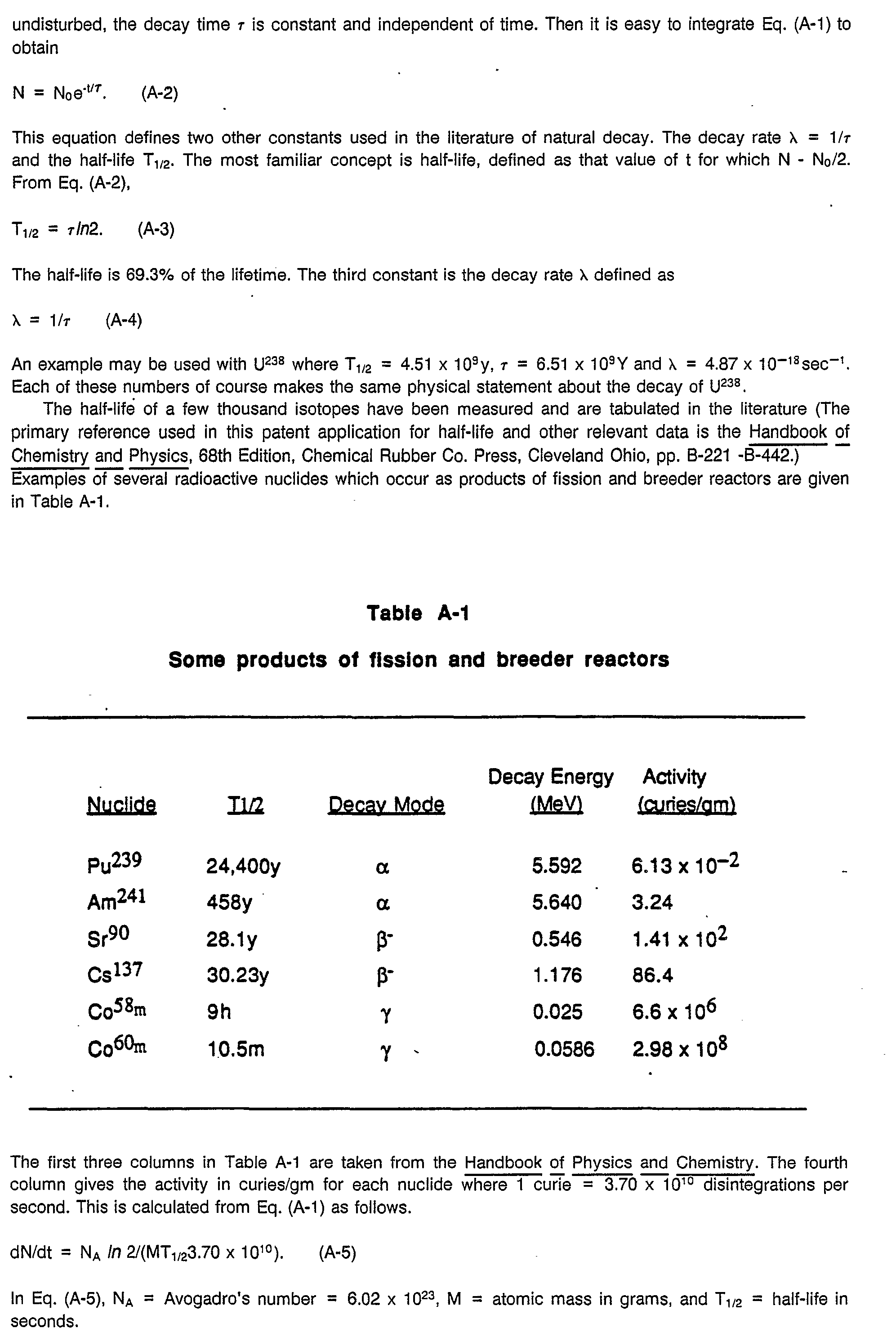
The theory of natural alpha decay is well established on both theoretical and experimental grounds. The derived lifetime expression is given by Eq. (A-7) in Appendix A. This relationship is
where τo is the natural lifetime, E is the alpha energy and Z is the atomic number of the daughter nucleus. This equation fits the lifetime-energy-atomic number data for alpha emitters very well.
-
The theory of accelerated alpha decay due to electrostatic voltage excitation is the essential feature of this and of the U.S. patent application Serial No. 112,854. It is discussed in detail in Appendices B and C along with supporting experimental data.
-
Eq. (1) is a convenient formula, which is easily obtained by subtracting (8) from (7). Quantitative experimental evidence for this effect is given for Th23° and other nuclides in Appendices B and C.
-
Thorium 230 has a natural half-life T1/2 of 75,400 years. This isotope decays to Pb206 through a chain of seven alphas and four beta minuses. In a test run, a Th230 source underwent electrostatic voltage excitation for twelve hours at - - 400 kV. After the generator was turned off, the radiation count decayed to background in about six weeks. It has remained stable at background for six months. In the Th230 decay chain there are three relatively long lived alpha decays and one twenty-one year beta decay. Evidently this excitation process removed all the alpha and beta activity in the Th230 source in a time which is extremely short in comparison with 75,400 years. Similar results were observed in the accelerted alpha decay of Po210.
Question
-
What is the excitation lifetime τ for Th230 at four operating voltages? ø = ± 250 kV and ø = ± 500 kV?
Answer
-
The results are given in Table 4. These are obtained from Eq. (1) using τo = 7.54 x 10
4y, Z =
88, and E = 4.658 MeV. The parameters for Th
230 are given in reference A-1, p. B-423. The energy value is a weighted average of the four values given in this reference.
-
The lifetime depends exponentially on the polarity and magnitude of the excitation voltage. Theory predicts and experiment confirms that the rate of alpha decay is extremely sensitive to voltage control. This voltage is the homogeneous excitation potential in the cavity of a charged electrostatic generator, such as a Van de Graaff generator..
Question
-
Is beta decay accelerated by electrostatic voltage excitation? What is the experimental evidence and is there a theory which accounts for this effect?
Answer
-
An electrostatic voltage excitation experiment on several beta emitters is described in Appendix D. One of these is Tl204 B Pb204-, T1/2 = 3.78y. The others are six beta minus emitters in the Th23° decay chain. The Pb210 β- Bi210 lifetime i the longest of these: T1/2 = 21y (see Table 3). All alpha and beta activity decayed t background about six weeks after the excitation. The principal depletion occurs during the excitation time, which in this case was twelve hours. This means that the beta decay lifetime was decreased by a factor of 365. This is substantial, but it is considerably less than the alpha lifetime reduction factor for Th230 which was 1.31 x 10⁶. The theoretical explanation for this observed accelerated beta decay is qualitative. It is not as well understood as the theory for accelerated alpha decay.
-
Consider atomic electrons in a beta minus emitter like 81 Tl204 and 82Pb210. The electrons occupy energy shells. They are easily ionized, given a suitable excitation, as in the photoelectric effect. The first two ionization potentials for TI and Pb are 6.12, 20.3 eV and 7.42 and 15.0 eV, respectively. Each atomic electron acquires an increased potential energy |eø |, if it is located inside a Van de Graaff cavity charged to a negative potential ø. At 6 = -350 kV for example, many of the electrons will be excited to ionization states. They are not accelerated inside the cavity, which is field free. Electrons near the surface of the sample may drift towards the surface of the terminal. However, the majority will remain inside the source volume. This cloud of "free" electrons is similar to the "free" electrons in a metal. It is well known that the Knight shift in the NMR frequency in metals is due to an electron density Ψ * Ψ (0) at the nucleus, which is greater than for non-metals.
-
It is believed that the mechanism for the observed increase in beta decay rates is that Ψ * ϕ (0) is increased as the atomic electrons are ionized. The electron density at the nucleus is a crucial parameter in the theory of beta decay, as discussed in Appendix A, Section I-C. A more detailed discussion of accelerated beta decay is given in Appendix D.
Question
-
Is gamma decay accelerated by electrostatic voltage excitation?
Answer
-
The answer is yes. An experiment on the gamma source Am241 demonstrates that electrostatic voltage excitation produces accelerated decay. A homogeneous negative electrostatic voltage excitation will decrease the potential energy of each proton in the atomic nucleus, just as it decreases the potential energy of an alpha particle. The charge distribution and shape of the nucleus will be disturbed and the gamma half-life will be changed. Negative voltages increase the gamma decay rate, positive voltage decreases the gamma decay rate. This was observed on a CS 137 gamma source.
III-C. Conversion from Fission Power to Alpha Power
-
The conversion of existing nuclear fission plants to alpha, beta and gamma reactors is quite simple in principle. The essential change is the replacement of the fission reactor core with an alpha, beta and gamma reactor core. The fission reactor cores usually use water as a coolant. The heat generated in the nuclear process is passed to the coolant which circulates through pipes totally enclosed in the reactor vessel. This fluid is conveyed to a heat exchanger where water in a secondary loop is converted to steam. The steam drives a turbine or other load which generates electricity. A schematic drawing is given in Fig. 3.
-
In Fig. 3, an electrostatic generator 50 has a cylindrical, hollow body 52 provided with an open end which is covered by an end plate 54 and secured in place to an annular flange 56 surrounding the open end of the body 52. Means 58 with control 71 is provided for charging the generator 50 to an electrostatic potential, such as in the range of 50 kV to 5,000 kV.
-
The body 52 is provided with a mass 60 of radioactive material which is to be used in generation of power by application of an electrostatic potential to the radioactive materials.
-
As the particle decay increases, a coolant flowing through an outer coil 62 surrounding body 52 carries heat energy to a heat exchanger 64 which transfers heat to another fluid in a closed loop 66 coupled with a load 68 to be driven by the energy imparted to the coolant in coil 62 by particle decay.
-
The numeral 70 in Fig. 3 represents a mass of a beta emitter which is used with generator 50 to provide sufficient electrons to cancel out the positive charges delivered by the alpha emitter 60 of the radioactive materials in the generator 50. A discussion of this feature follows hereinafter.
-
In the typical fission reactor, there are about 180 fuel assemblies each consisting of about 200 fuel rods. Each rod consists of U02 pellets 5 mm in diameter and 10 mm long, inserted in a thin walled stainless steel tube. This tube is referred to as cladding. It keeps the fission products from getting into the coolant water. Each fuel assembly weighs 545 kg. The total weight of the complete fission power assembly is about 98.1 metric tons. Fission power is activated by thermal neutrons. Control rods made of Boron1 or Cadmium113, with high neutron capture cross sections are used to maintain the desired power level. If the control rods are lowered into the assembly, the power level decreases. If they are raised, the power level increases.
-
In the alpha reactor it is not necessary to use as much fuel as in the fission reactor. This is because the alpha energy stored in a rod consisting of 97% U238 and 3% U235 is about 8.46 times greater than the potential fission energy, as explained earlier. Twenty-four assemblies, each consisting of 200 spent fission fuel rods will suffice. The total weight is about 13.1 metric tons. Alpha, beta and gamma power is activated by an electrostatic generator 50 (Fig. 3). The fuel assemblies are loaded in the cavity of the high voltage terminal. Control is maintained by the polarity and magnitude of the DC voltage on the generator terminal. A negative voltage increases the alpha power. A zero voltage shuts the power off, but not completely. There is a low level of oscillating power production which may persist for a few weeks.
-
This may be damped out by a positive voltage. If the voltage is set at about- 630 kV, the lifetime of both U238 and Th232 fuel is about 25 years. When the total fuel weight is 13.1 metric tons, the power generated is about 360 MW for U238 and about 315 MW for Th232.
-
The interior volume of a conventional electrostatic generator 50 (Fig. 3) can easily accomodate 13 metric tons of U238 or Th232. The density of U02 and of Th02 is 10.96 and 9.86 gm/cm3 respectively. The National Electrostatics Co. electrostatic generator, Pelletron Model 5SDH-2, is equipped with an accelerator tank which is 3.71 m in length and 1.07 m in diameter. The corresponding volume is 3.34 m3, which is about 2.5 times the volume of the fuel.
-
III-D. The Current Delivery Requirements of the Electrostatic Generator. Charge Compensation Using Beta Emitters.
-
On the conventional Pelletron accelerators used in nuclear physics research, mass spectrometry, etc., the high voltage on the terminal is generated by a charging chain system. This consists of metal pellets joined by insulating links. Charge transfer is by a controlled induction system. Desired terminal voltages are maintained within less than 1 %. The charging system must be large enough to maintain a voltage of-630 kV for a fuel lifetime of 25 years. However, the negative charge on the terminal surface is being continuously reduced by the alpha particles released from the source.
Question
-
What current is delivered to the terminal of an electrostatic generator operating at - 630 kV, loaded with 13.1 metric tons of U238 or Th232?
Answer
-
The number of alpha particles produced per second is
where No = MN
A / M
At. Here M = mass of fuel, M
At = atomic mass and N
A = Avogadro's number. Each alpha particle which reaches the terminal surface reduces the negative charge there by two electrons.
-
Then the maximum electron current required to compensate for this loss is
-
This value is clearly an upper limit since many of the alpha particles will become neutralized by the atomic electrons inside the source. In any event, charge compensation poses a design problem. The conventional electrostatic generator is a high voltage, low current device with typical operating currents of about 200-250 microamps, far below the current needed for a large fuel load.
Question
-
Is it possible to maintain. a voltage of - 630 kV on a conventional electrostatic generator and simultaneously compensate for a postive alpha current - 13.5 amperes?
Answer
-
Yes. There is a simple and economical solution. Consider the beta emitters Sr90, CS 137 and Kr85 in the spent fuel rods. The negative charges emitted by these isotopes will compensate, in whole or in part, for the positive alpha emitters. Electrostatic voltage excitation speeds up beta as well as alpha emission. Evidence for this is given in Appendix D and is discussed in Section III-B of this patent application.
-
Let us assume that beta decay rates are enhanced by a factor of 30-35 under the influence of a negative voltage - - 630 kV. The actual enhancement factor may be much higher, as in the case of Pb210-(see Section III-B and Appendix D).
Question
-
What approximate mass of beta emitters will compensate for the positive charge delivered by 13.1 metric tons of alpha, beta and gamma fuel?
Answer
-
Using the data for Sr9°, Kr95 and CS 137 from Table A-11 and D-1, the average enhanced activity is 6.77 x 10³ curies/gm or 2.51 x 10¹⁷ disintegrations/sec. This means that 337 kilograms of these beta emitters will provide sufficient electrons to cancel out the positive charges delivered by the alpha emitters. This mass is 2.6% of the total mass of the 13.1 metric tons of spent fission fuel. If the actual mass of beta emitters in the spent rods is less than this, the fuel could be enriched with beta minus sources.
-
Once the electrostatic voltage excitation process is underway, the beta emitters Th230 and Pa234 will facilitate the consumption of U238. They are the next two isotopes in the U238 chain (See Table 1). Similarly the beta emitters Pa228 and Ac228 will facilitate energy release in the Th232 chain (see Table 2).
III-E. Conclusion
-
- 1. Spent nuclear fission rods and naturally occurring U238 and Th232 are rich in energy.
- 2. The energy content of a spent nuclear fission rod is more than eight times greater than the fission energy of a fresh fuel rod, enriched with 3% U235.
- 3. Electrostatic voltages change alpha, beta and gamma lifetimes so that power can be obtained from these sources.
- 4. A negative voltage accelerates alpha decay. A positive voltage decelerates alpha decay. The lifetime of U238 and Th232 is decreased from billions of years to 25 years by an electrostatic voltage of about - 630 kV:
- 5. Conventional fission power reactors can be replaced by alpha power reactors. State of the art electrostatic generators have cavity volumes which can easily accommodate 13.1 metric tons of radioactive waste. Operating'at - 630 kV, they would generate 350 MW, requiring 4% fuel replacement annually.
- 6. The best candidate for the coolant fluid is water. (Helium is not satisfactory because it is not a good electrostatic insulator).
- 7. Conventional electrostatic generators are low current, high voltage devices. The charging current is 200-250 microamps. By itself, this low charging current cannot possibly maintain a voltage of - 630 kV if the substantial alpha current from a large fuel source is not neutralized. This problem can be solved by using beta emitters as charge compensators. It may be that the spent fuel rods contain long lived beta emitters in sufficient quality. If not, the alpha fuel could be supplemented with a few hundred kilograms of beta minus fuel.
- 8. The power level in an alpha reactor can be controlled by controlling the polarity and magnitude of the voltage. The power output will increase with the magnitude of the negative voltage. When the voltage is set to zero, the fuel undergoes slow transient oscillations. A positive voltage can be used to quench the activity. Voltage in an alpha, beta and gamma reactor plays a role similar to the control rods in a fission reactor.
- 9. The byproducts of an alpha reactor are helium and lead, which are both stable. The process removes all of the radioactive nuclei.
IV. Fusion Power
-
The deuteron-deuteron fusion process complements the alpha decay process. Both occur by Coulomb barrier modification. (See reference A-2, Gasiorowicz, p. 93 and M.G. Bowler, Nuclear Physics, Pergamon Press, Oxford, 1973 p. 272 and 322.) The electrostatic voltage excitation process is capable of inducing Coulomb barrier penetration by deuterons at low ambient temperatures. The theory of this effect and its experimental verification with small samples of water is given in Appendix E.
IV-A. Fusion by Voltage Excitation as Compared to Fusion by Thermal Excitation
-
As described in Appendix E, deuteron-deuteron fusion in a drop of water was induced by a voltage of -- 1 kV, at T = 300° K. The water showed no activity prior to voltage excitation. After excitation, the Geiger counter detected an activity as high as thirty times background. The drop evaporated completely in one hour. After the voltage was switched off, the count continued substantially above background for about two hours.
-
According to conventional wisdom (Edward Teller, Fusion, Academic Press, New York (1981) p.3; Samual Glasstone and Ralph H. Lovberg, Controlled Thermonuclear Reactions, Robert E. Krieger Publishing Co., Malabar, Florida (1975) p. 14 and 18; and H. Motz, The Physics of Laser Fusion, Academic Press, London (1979) p. 1 and p. 224.) , the essential condition for nuclear fusion is a high temperature. In fact, this is a sufficient condition but it is not necessary. It is important to note the temperature equivalent of one electron volt.
where e = 1.602 x 10-
19 coulomb and k = 1.381 x 10-
23 joules/° K. This means that 1000 eV is equivalent to 1.16 x 10⁷ ° K, which is well within the thermonuclear range. Extremely high temperatures occur in stellar interiors and in hydrogen bomb explosions, where fusion takes place. This is the reason attention has been focused on temperatures in excess.of 1060 K. Fusion by voltage excitation represents a completely different and essentially new approach.
IV-B. Dependence of Fusion Fuel Lifetime on Electrostatic Excitation Voltage
-
The theoretical expression (see Appendix E) for the deuteron-deuteron fusion lifetime by voltage excitation is
where τo = 1.12 x 10
-18 seconds is the estimated nuclear well transit time and
-
Here a = the fine structure constant = 1/137, µc
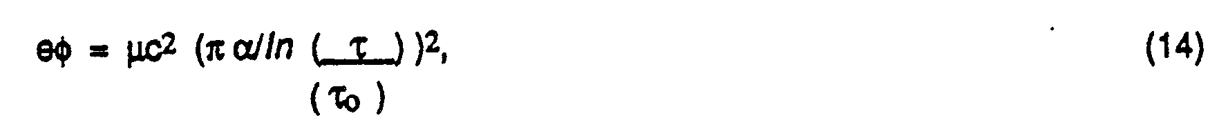
2 = 931.022 MeV and |eø is the excitation energy. For a given lifetime τ, the corresponding excitation voltage may be calculated from,
an expression which follows immediately from (12) and (13). In Table 5, the excitation voltages required for five deuteron-deuteron lifetimes are obtained from Eq. (14).
-
In the derivation of Eq. (13), it is assumed that the excitation energy of the deuteron and of the hydrogenic electron in the deuterium atom are additive and of the same order of magnitude. If this is not the case, the ϕ values in Table 5 may be off by a factor of two or so.
Question
-
The excitation voltage required for a 25 year lifetime for deuteron fuel is -129 volts as compared to - 630 kV for U238 and Th232. Why is there such a large difference?
Answer
-
The probability for a deuteron or an alpha particle to penetrate the Coulomb barrier is proportional to the Gamow factor, T*T = e
-G. The G value is much smaller for deuteron fusion than for alpha decay. Therefore, the excitation voltage requirement for a given lifetime for fusion is much lower than it is for alpha decay. This point is clarified by comparing the maximum Coulomb barrier heights for these two processes. See Table 6.
IV-C. The Energy Content in Deuterium Fuel
-
The deuteron-deuteron reaction equations are well known. (See reference 3, Glasstone and Lovberg). The primary reactions are
and
-
These are known as the neutron branch and the proton branch, respectively, of the D-D reaction. In this fusion process the neutrons will escape from the reacting system and deposit their energy elsewhere. Only the energy of the charged particles may be used to generate electricity and this amounts to 4.85 MeV. In secondary reactions, deuterons interact with the He
3 found in the neutron branch and with the tritium found in the proton branch.
-
These four reactions yield 26.65 MeV of usable energy. If a lithium moderator is used to slow down the neutrons, the resulting thermal neutrons can be captured by Li
6 with a further release in energy.
-
Thus six deuterons release 31.25 MeV, which may be used to generate electricity. The tritium may be used again in a D-T reaction. The products of this series of fusion reactions are helium, hydrogen, neutrons and - 5.21 MeV of energy for each deuteron. Table 7 gives the energy content in deuterium.
-
The combustion of one gallon of gasoline yields about 1.255 x 10⁸ joules. The deuteron fuel energy in one gallon of water is equivalent to about 300 gallons of gasoline.
IV-D. Nuclear Fusion Power Reactor Core Design Question
-
If the lifetime of the fusion fuel is one month, corresponding to an excitation voltage ø = -158 volts, how many liters of water are required to deliver a power level of 350 MW?
Answer
-
From Table 7, the energy content in one gallon of water is 3.740 x10¹⁰ joules. This is due to the deuterons in the water. There are three hydrogen isotopes 1H1, 1D2 and 1T3. The proton is by far the most abundant, at 99.988%. The deuteron has a natural abundance of 0.015%. Tritium undergoes beta decay with a half-life of twelve years. The entries in the fourth and fifth columns of Table 9 are calculated from this natural abundance data. Using the fact that one gallon = 3.785 liters, it follows that the deuteron fusion energy content in one liter of water is 9.88 x 10⁹ joules. The number of liters required for a given power level P and lifetime r is given by the relation
-
Question
-
What design factors are appropriate for an effective fusion reactor?
Answer
-
Consider a fuel tank whose volume is 91.8m3 filled with 91.8 x 10³ liters of ordinary water or sea water. This is the' volume, for example of a cylinder 7.76 m in length and 3.88 m in diameter. The tank shell should be a good conductor like aluminium or steel. Fusion takes place when an excitation voltage of - - 158 volts is applied to this surface.
-
A grounded pressure vessel surrounds the fuel tank. This accomodates the coolant fluid. Either of two coolants used in fission reactors could be used, helium gas or water. The coolant fluid transfers the heat generated in the fusion process to the heat exchanger, where water is converted into steam. The steam drives a turbine which generates electrical power. See Fig. 3.
-
The apparatus of Fig. 3 is suitable for use to provide power from the deuteron-deuteron fusion process. To this end, body 52 of generator 50 can be partially or completely filled with water and a charging means 58 operated to provide an excitation voltage in a certain range, such as 100 volts to 2,000 volts. A coil 62 provides a grounded pressure vessel surrounding body 52 of generator 50. The energy produced within body 52 will be carried by the coolant in coil 62 to the heat exchanger 64 where heat energy is provided to the fluid in loop 66 coupled to load 68. Charging means 58 has a means 71 for varying the polarity and magnitude of the voltage applied to body 52.
Question
-
How is power controlled in a fusion reactor?
Answer
-
The power level is controlled by varying the voltage on the surface of the fuel tank by control means 71. The electrostatic voltage excites the fuel inside the tank. If ϕ is negative and is increased in magnitude, the power level rises. If ø is turned to zero the power level exhibits transient. oscillations which decay to background. They can be damped out by a positive voltage. An equivalent circuit may be used to represent control means 71. See Fig. 4.
-
For illustrative purposes, typical values are used for the emf, the source resistor Rs, the Capacitance C and the load resistor RL.
-
The emf, e, is provided by a DC generator or by heavy duty batteries capable of delivering substantial current. Take c = 165 volts. If a negative voltage of this magnitude were used to excite deuteron fuel, the lifetime calculated from Eq. (12) and Eq. (13) would be 7.2 days. A variable resistor R
s is used to regulate the voltage which appears across the capacitor. The negative electrode of the capacitor is the conducting surface of the fuel tank. The grounded terminal is the pressure vessel. The dimensions of this cylindrical capacitor are shown in Fig. 5.
-
If R
s is shorted out, the voltage difference across the capacitor is 165 volts. For this voltage, the charge on the negative terminal is
-
As in the case of accelerated alpha decay, there is a positive current generated by fusion which will neutralize electrons on the surface of the fuel tank. Charge compensation must be provided to sustain the fusion process.
Question
-
How many deuterons are there in 9.18 x 10⁴- liters of water? What is the corresponding positive deuteron current developed in the fusion process?
Answer
-
The mass m of the water is 9.18 x 10
7, using 1 liter = 10
3cm
3 and a water density p = 1 gm/cm
3. The number of deuterons in this mass of
H 20 is
where N
A = 6.02 x 10
23, m = 9.18 x 10', M
A = 18 grams and the
% ab 2(.015%). The positive deuteron current is
-
Typical values are given in Table 8.
-
The purpose of the load resistance RL is to draw an electron current from the seat of EMF which neutralizes the positive deuteron current.
-
Suppose
then R
L = εe/l
d = 165/237 = 0.696 ohms.
Question
-
For what value of Rs will the voltage across the capacitor be 158?
Answer
-
IV-E. Fusion Power for Home Heating, Automobiles, Buses, Trains, Airplanes and Ships
-
The design of fusion reactors for home heating and to power vehicles is quite similar to the design of a fusion reactor for a nuclear power plant. However, all the parameters are scaled down.
Question
-
Consider a typical automobile with a rated horsepower = 150 and a 15 gallon tank. If water is used as a fusion fuel, how many gallons are required to produce 150 hp at an excitation voltage of - 158 volts?
Answer
-
One horsepower = 745.7 watts. From Table 7, fusion energy in one gallon of water is 3.74 x 10¹⁰ joules. The fuel lifetime for an excitation voltage of - 158 V is 30 days. From this data, the number of gallons of water required is 7.76.
Question
-
How many deuterons are there in 7.76 gallons of water and what positive current do they deliver?
Answer
-
Question
-
In the DC circuit of Figure 4, choose 6= -165 volts. If Rs = 0, what is ID and for what value of RL will the electron current cancel lo?
Answer
-
Question
-
For what value of Rs is the voltage across the capacitor 158 volts?
Answer
-
The fusion core in automobiles could be air cooled or water cooled.
IV-F. Radiation Hazards due to the Fusion Process
-
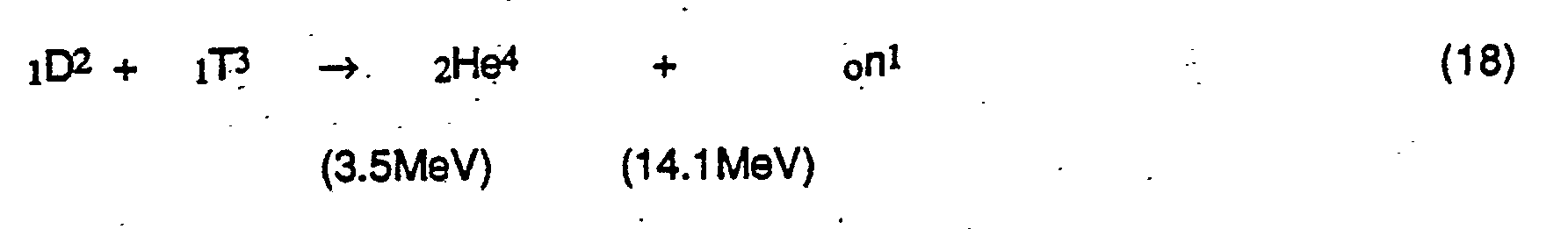
The deuteron-deuteron fusion process produces energy, helium, hydrogen and neutrons. The neutrons have energies of 2.45 and 14.1 MeV, (Eqs. 15 and 18). Water in the fuel and in the coolant acts as a moderator. This thermalizes the fast neutrons. These slow neutrons can be substantially reduced if the reactor core is lined with boron or cadmium. These materials have a high capture cross section for thermal neutrons.
-
It is not necessary to use heavy lead shielding to protect against harmful fusion radiation. This is why fusion energy is a practical source of power for all types of vehicles and of heat for homes and other stationary structures.
IV-G. Conclusion
-
- 1. Fresh water and salt water are rich in deuteron fusion energy.
- 2. Although the natural abundance of deuterium is only 0.015%, the fusion energy content of one gallon of water is equivalent to 300 gallons of gasoline.
- 3. Electrostatic voltage excitation induces D-D fusion by Coulomb barrier modification.
- 4. An electrostatic voltage of - - 158 volts results in a fusion lifetime of - one month.
- 5. The excitation voltages for a given fusion lifetime are small in comparison with those for accelerated alpha decay with the same lifetime because of the large difference in Coulomb barrier height.
- 6. A fusion power reactor capable of generating 350 MW requires - 9 x 10° liters of water and an excitation voltage - - 158 volts. This reactor would deplete the deuterons in 3,000 liters per day, producing 9 x 10⁴ liters of "light water" in one month.
- 7. Water or helium can be used as the coolant fluid in fusion reactors. Water is preferable because it also serves as a moderator for energetic neutrons.
- 8. The low excitation voltages needed for fusion permit the use of DC generators or heavy duty batteries in the energizing circuitry. Charge compensation for the deuteron current is provided by a choice of load and source resistance values.
- 9. The control of fusion power levels is achieved by adjusting the excitation voltage.
- 10. The products of the deuteron-deuteron fusion process are energy, hydrogen, helium, light water, and neutrons.
- 11. Radiation problems due to D-D fusion can be minimized by using water as a moderator to slow the fast neutrons, and cadmium or boron to capture the thermalized neutrons..
- 12. Fusion reactors may be used to generate electrical, mechanical or heat energy on a large scale, as in a 350 MW power plant, or on a small scale, as in a vehicle or a home. The design is..simply a scaled down version of the design for a large fusion power reactor.
- 13. Controlled fusion experiments have been done a number of times in a small Van de Graaff generator with a small quantity of water, as described in Appendix E. Substantial counting above background is observed several feet from the water, when the generator is turned on. The water evaporates rapidly.
- 14. Agreement between theory and experiment in the fusion process, induced by electrostatic voltage excitation is qualitative, not quantitative.
V. Production of Valuable Products by Transmutation, using Electrostatic Voltage Excitation
V-A. General Considerations
-
Electrostatic voltage excitation accelerates or induces decay. The decay energy Q, of a nuclide which disintegrates spontaneously, is positive. The process is exothermic and occurs with a lifetime r, which ranges from microseconds to billions of years depending on Q and the charge of the daughter nucleus. Electrostatic voltage excitation changes the potential energy of alpha particles, protons, and atomic electrons. This has an exponential effect on the lifetime of alpha emitters and a substantial effect on the lifetime of beta and gamma emitters. This is discussed in Appendices B and C and in Section III-B of this patent application.
-
The decay energy Q, of a nuclide which is stable against alpha decay is negative. The process is endothermic. No spontaneous decay occurs. Electrostatic voltage excitation with a potential energy IVI>IQI will induce decay with a lifetime T, which for alpha decay decreases as the magnitude of the negative voltage increases. The weak interaction decay rate is also increased, but not exponentially as it is in alpha decay.
-
The voltage required to induce is in the MW range. This is readily available in standard research electrostatic generators. If the sample is small enough, the generator's charging current of - 200 microamps will suffice to maintain a few million volts on the terminal. For larger samples of alpha emitters, the positive alpha current can be offset if a sufficiently large beta minus source is introduced into the generator cavity. If this is not done, the negative charge on the terminal will become neutralized, the negative potential will decrease in magnitude, and the generator motor will heat up due to the overload. Electrostatic generators are designed to switch off if they become overheated.
-
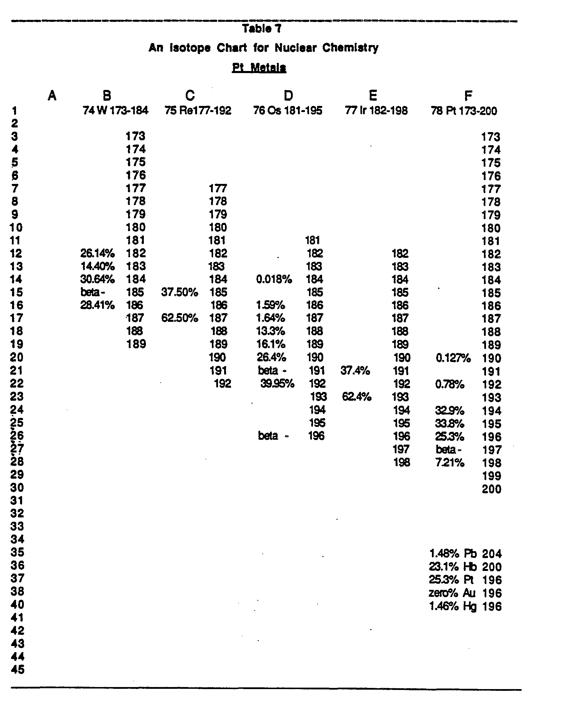
Nuclear chemistry is greatly simplified by the use of isotope charts like the one exhibited in Table 11. The construction of a decay scheme is straightforward, and it leads from a stable and inexpensive isotope to a valuable isotope by successive induced or spontaneous alpha and beta minus decays.
V-B. The Production of-Rhodium for Silver
-
Consider 45Rh103, a stable isotope of rhodium with a natural abundance of 100%. There is substantial demand for rhodium, which is used as an alloy to harden platinum and palladium, as a catalyst and in jewelry. The supply of rhodium is quite limited and it is the most valuable precious metal. Only about eight tons are produced annually worldwide. According to Skilling's Mining Review, November 28, 1987, metal prices per ounce were: Silver, 6.88; Gold, 470.85; Platinum, 500.00; Rhodium, 1200.00
-
Rhodium may be produced from the stable isotopes of silver by induced alpha decay.
-
Although both of the reactions (30) and (31) lead to rhodium, only the first is considered here. The second process leads back to Ag107 (and then to Rhodium 103) via a long beta decay. Although beta decay is enhanced by electrostatic voltage excitation, not enough is known to be able to make design calculations. However, the design equations are availbale for induced alpha decay.
-
Quantitatively, the first step is to calculate the decay constants for the reactions which describe the production and decay of rhodium.
and
-
These are found, as illustrated in Appendix A, Eq. A-17 by
where Mp = mass of parent in amu, M
d = mass of daughter and Mα = alpha particle mass. The results are
and
-
Both Q values are endothermic, with rhodium more stable against alpha decay than silver.
-
The second step is to choose an excitation voltage which results in a convenient lifetime. The theoretical formula (see Eq. (8) in Section III-B) is
Here E
1 = Q
1 + 2|eø|, Z
1 = 45.
-
If 24 hours is chosen as the Ag107 lifetime, the corresponding voltage is -2.30 MV.
-
The third step is to calculate T2 using Eq. (35), but with Z2 = 43, E2 = -3.12 + 4.60 = 1.476 MeV. The resulting τ2 = 3189 days, which is large compared to τ1. Since the rhodium lifetime is much longer than that of the silver parent, the two decays are effectively decoupled; the first decay is finished before much happens in the second. (Bernard L. Cohen, Concepts of Nuclear Physics, McGraw Hill Book Co., New York, (1971), p.198.)
-
Fourth, calculate the rhodium yield starting with one kg of natural Ag after an excitation period of 24 hours. In this calculation only the more abundant isotope of Ag (51.8%) is considered.
-
Using the decay equation
it follows that
-
The rhodium yield is
with No = 0.518 kg, the amount of rhodium synthesized in 24 hours is 327.7 gm.
-
Fifth, it is important to determine whether or not a charging current of 200 microamperes delivered by the Van de Graaff is adequate.
-
The current delivered by the alphas from silver is
-
This means that the Van de Graaf charging current is not adequate. Charge compensation may be provided by negative charge carriers from beta decay sources, as described in Section III-D.
V-C. The Production of Platinum from Mercury
-
Consider the stable isotopes of platinum. All of these are potential alpha decay daughters of stable isotopes of mercury. The Q values for each of these processes, calculated from Eq. (33) are given in Table 10.
-
Table 10 shows that 80% of the stable isotopes of mercury decay by induced emission to 100% of the stable isotopes of platinum. The Q values for the production and decay of platinum are all exothermic.
-
In Table 10, process a is unfavorable because it involves only a minute amount of mercury. Processes b, c and d in Table 10 pose difficulties because for any given voltage ø, the platinum formed will decay much faster than the mercury. However, process e in Table 10 is favorable. Hg202 has a natural abundance of 29.65%. The Q for platinum production is larger than the Q for platinum decay.
-
Consider a one kg sample of Hg
202. Choose τ
1 = 24 hours. This fixes the values of ø and
T2 according to
where Z
1 = 78, Q
1 = 0.1374 MeV, Z
2 = 76 and E
2 = 2|eø|
1 + Q
2 -
It at t = 0, the mass of Hg
202 is m
o = 1 kg, then after a time t the mass of pt
198 will be
-
This expression is well known (Reference 15,p. 187.) from the theory of radioactive decay.
-
The percentage yield Y(t) = m
2(t)/m
o is zero at t = 0 and at t = ∞. Therefore, there is a value for the excitation time for which the yield is a maximum. Setting dY(t)/dt = 0, it follows that
-
In Table 13, the parameters relating to the maximum yield of Pt
198 are listed.
-
Hence, one kg of Hg202 will yield 125 grams of Pt198.
-
It is reasonable to assume that a more sophisticated scheme can be developed for the extraction of platinum from all of the stable isotopes of mercury.
V-D. The Production of Gold and of 80Hg196
-
There is only one stable isotope of gold, and it may be synthesized from 80Hg201 as follows.
- 80Hg201 a 78Pt197 Induced alpha decay
- 78Pt197 B- 79Au197 Spontaneous β- decay T1/2 = 18.3 h (44)
-
Consider soHg'96, a stable isotope of mercury, with a low natural abundance of 0.146%. Although it is not as well known as rhodium, platinum or gold, it is considerably more valuable. A low pressure mercury vapor lamp is about 5% more efficient if the concentration of 80Hg196 is enriched to about 4.4%. This modification does not require a significant change in the features of the fluorescent lamp. If all of the Hg-rare gas fluorescent lamps were enriched in this fashion (J. Maya et al, Science, (1984), pp. 226 and 435.) the United States would amount to 200,000,000.00.
-
At the present time there is an effort being made at the Lawrence Livermore National Laboratories to produce
80Hg
196 by laser isotope separation. The synthesis of this isotope by electrostatic voltage excitation represents an alternate approach. A starting point in the production of
80Hg
196 is the
80Hg
200 isotope of mercury with a natural abundance of 23.1%.
Instead of exciting induced alpha and beta minus decay, it is possible to induce an appropriate fusion process.
- 42Mo100 +42Mo100 fusion - 84Po200 a 82Pb196 Induced fusion and spontaneous alpha decay
- 82Pb196 EC 81Tl196 EC and beta plus 11.5 m
- 81Tl196 EC 80Hg196 EC and beta plus 1.13 h
-
The synthesis of Hg196 is more likely to decay than by fusion. The fusion of Mo100 requires an excitation voltage in excess of -77.6 MV. This is beyond the capability of state of the art electrostatic generators.
V-E. The Production of Other Valuable Isotopes
-
The examples given are illustrative, not comprehensive. The electrostatic voltage excitation process is available for the production of any valuable isotope which is important in industry, basic research or medicine. A decay scheme can be found which leads to such an isotope, starting with plentiful, relatively stable isotopes like Bi209 (100%), Pb204 (1.4%), Pb206 (94.1%), Pb207 (22.1 %) and Pb208 (52.4%). The specific path to use is facilitated by the charts given in Table 7.
V-F. Conclusion
-
- 1. Abundant relatively stable isotopes like lead, bismuth and mercury represent the starting point for the production of valuable isotopes.
- 2. Electrostatic voltage excitation induces alpha, beta and gamma decay and fusion, (for Z - 1). This is a transmutation process.
- 3. The induced decay lifetime depends on the Q of a given nuclear reaction and on the excitation voltage. The Q can be calculated from mass-energy considerations.
- 4. In most of the induced processes, the voltage is in the MV range. This is higher than for either fusion or accelerated alpha decay.
- 5. Examples of production by transmutation are rhodium, Pt198, gold and Hg196.
- 6. Attempts to synthesize valuable isotopes should be done initially with small samples and voltages which are less then optimal.
- 7. After these feasibility tests are made, production runs with larger quantities of source material may require the use of beta minus emitters in the electrostatic generator to compensate for the alpha current.
VI. Summary
-
- A. The electrostatic voltage excitation process and apparatus of the present invention has four major applications; 1) Decontamination of radioactive waste, 2) Generation of alpha power as an economical substitute for fission power, 3) Generation- of fusion power, 4) The production of valuable isotopes by transmutation.
- B. The availability of the electrostatic excitation process represents a major scientific and technological advance with far reaching economic implications.
- C. As with other significant technical developments, the implications of the electrostatic excitation process have encountered incredulity on the part of the scientific community.
- D. According to conventional wisdom, the half- life of a radioactive source cannot be changed. It is immutable, like the charge on an electron or Planck's constant. Yet, nowhere in the literature is this assertion made.
- E. The current situation has a parallel with an incident which took place in the 1950's. At the time scientists "knew" that noble gases like Ne, Xe, and Kr could not combine into molecules. When XeF4 was synthesized at the Argonne National Laboratories, this myth was abandoned.
- F. Electrostatic voltage excitation refers to the potential energy acquired by a charged particle when it is placed in a region of homogeneous potential and zero field. The potential energy V = qo, where q is the charge of the particle and 0 is the potential.
- G. The device which creates a constant potential, field free region is an electrostatic generator, like the Van de Graaff. It has a high voltage terminal which consists of a spherical metal shell, enclosing a cavity. Inside the cavity there is no net charge. By Gauss' theorem the cavity is field free and the potential is constant everywhere, the same from point to point. Outside the cavity, the potential and the field go to zero with increasing distance from the cavity center. Inside the cavity, a charged particle is not accelerated as there is no field, while outside the cavity a charged particle is accelerated, as there is a field. The potential and field, inside and outside a spherical cavity, are sketched in Fig. 6.
- H. The cavity surface may be charged negatively or positively. Consider ø negative, corresponding to a negative charge delivered to the surface by the generator's belt system
- 1) The potential energy of an alpha particle decreases by -2|eø|. The total potential energy of an alpha particle in the interior of an alpha emitter is 2Ze2/r -2|eø|. This decrease in the Coulomb barrier results in accelerated decay. For a detailed theoretical treatment, see Appendix C.
- 2) The potential energy of a deuteron is decreased by - |eø|. The total potential energy of a deuteron in water is e2/r - |eø|. This decrease in the Coulomb barrier permits induced D-D fusion. See Appendix E.
- 3) The potential energy of an electron is increased |eø|. If ø > 103 volts, the atoms in a beta emitter, for example, will experience several stages of ionization. As the region is field free, the electrons remain in the vicinity of the ions. This cloud of "free electrons" increases the charge density at the nucleus accelerating beta decay. The effect is quite similar to the Knight shift in metals, where the "free electrons" in the conduction band lead to a higher nuclear magnetic resonance frequency than is observed with the same nucleus in a non-metal.
- 4) The potential energy of a proton is decreased -|eø|. In a gamma emitter, for example, the protons in the nucleus undergo a redistribution of charge which changes the shape of the nucleus, inducing decay at a faster rate.
- I. The lifetime for natural alpha decay is well known.
Inside the cavity of an electrostatic generator with a negative voltage ø, the lifetime becomes
- J. Equation (2) describes the effect of Coulomb barrier modification on alpha decay. It is the central equation of this theory and is readily derived from
where e-G is the Gamow barrier penetrability factor and Too represents the time it takes for an alpha particle to move back and forth inside the nuclear well.
- K. Experimental evidence for the validity of Eq. (1) exists in the literature. Experimental evidence for the validity of Eq. (2) is presented in this patent application in Appendices B and C. The theory is confirmed for 90Th230 and for 84Po210 for voltages ranging from -50 kV to -400 kV.
- L. Independent calibration before and after high voltage excitation has been made for Th230 and Po210. In both cases it was observed that the initial untreated alpha count decreased to background six weeks after excitation.
- M. The experiment performed to test Eq. (2) demonstrated that soTh23° and all of its alpha and beta daughters decayed to background in about six weeks following a voltage excitation of -400 KV for twelve hours. Th230 has a lifetime τo = 1.08 x 10⁵y. This experiment showed that beta decay is also accelerated by the voltage excitation process. The beta emitter T1204 also decayed to background in the same time period.
- N. The theory of accelerated beta and gamma decay is not understood quantitatively. This area needs further study.
- O. Eqs. (1) and (2) are time independent. They describe natural and accelerated alpha decay. When the generator is turned off, ϕ = 0. There follows a reaction response which continues for days. This reaction mode is not understood, but it is similar to the transient decay which occurs following any type of excitation. The excitation process at high electrostatic voltage and the reaction process at zero voltage together lead to accelerated decay. For a more detailed discussion, see Appendix C.
- P. When the Thorium 230 decays to lead, it releases energy as is well documented in the literature. If this release is accelerated, the power generation increases. This has not been directly tested experimentally.
- Q. Decontamination and power generation by alpha, beta and gamma decay are practical applications of Eq. (2). See I. and K. of this section.
- R. It is well known that alpha decay and controlled deuteron-deuteron fusion occur by Coulomb barrier penetration. The theory of Coulomb barrier modification for deuterons, by electrostatic voltage excitation, follows directly from Eq. (3) with an appropriate Gamow factor e-G. Experimental verification at ambient temperatures has been achieved. A few drops of water inside a Van de Graaff terminal were excited by voltages of about 1000 V. Substantial activity above background was observed by a Geiger Muller counter several feet away from the generator.
- S. Experimental verification of the D-D fusion is planned in other ways.
- 1) The detection of neutrons which are produced in the neutron branch of the primary D-D fusion. This will be done with a BF3 counter or a silver foil.
- 2) Capture and detection of 2He4 produced in the fusion process.
- 3) Measurement of the heat generated in the fusion process.
- T. Decay is accelerated by electrostatic voltage excitation. Fusion is induced by the same process. It follows that alpha decay may be induced, given sufficient excitation energies. With voltages of the order of 106V; the production of rhodium, platinum, gold and Hg196 can be achieved.
- U. Experimental verification of the production of valuable isotopes has not been done. A feasibility experiment of this type is being planned using a Pelletron in the MV range. The synthesis will probably be rhodium from silver, as this is the most straightforward.
- V. For the sake of safety, experimental work using electrostatic voltage excitation should be initiated with small samples.
- W. The basic concept of electrostatic voltage excitation, described by F. and G. in this summary is simple. The implications of this concept, for the four areas of nuclear chemistry discussed in this patent application, are not at all obvious. The electrostatic generator, invented by Van de Graaff in 1931 has a number of applications in nuclear physics, but none of these involve electrostatic voltage excitation. The accelerated decay experiments described in Appendices B and C were performed to test the validity of the theory which was developed several years earlier. Both the theory and related experiments are new.