EP0363988A2 - Color scanner and automatic setting method - Google Patents
Color scanner and automatic setting method Download PDFInfo
- Publication number
- EP0363988A2 EP0363988A2 EP89119085A EP89119085A EP0363988A2 EP 0363988 A2 EP0363988 A2 EP 0363988A2 EP 89119085 A EP89119085 A EP 89119085A EP 89119085 A EP89119085 A EP 89119085A EP 0363988 A2 EP0363988 A2 EP 0363988A2
- Authority
- EP
- European Patent Office
- Prior art keywords
- original
- signal processing
- image
- section
- basis
- Prior art date
- Legal status (The legal status is an assumption and is not a legal conclusion. Google has not performed a legal analysis and makes no representation as to the accuracy of the status listed.)
- Granted
Links
Images


Classifications
-
- H—ELECTRICITY
- H04—ELECTRIC COMMUNICATION TECHNIQUE
- H04N—PICTORIAL COMMUNICATION, e.g. TELEVISION
- H04N1/00—Scanning, transmission or reproduction of documents or the like, e.g. facsimile transmission; Details thereof
- H04N1/40—Picture signal circuits
-
- Y—GENERAL TAGGING OF NEW TECHNOLOGICAL DEVELOPMENTS; GENERAL TAGGING OF CROSS-SECTIONAL TECHNOLOGIES SPANNING OVER SEVERAL SECTIONS OF THE IPC; TECHNICAL SUBJECTS COVERED BY FORMER USPC CROSS-REFERENCE ART COLLECTIONS [XRACs] AND DIGESTS
- Y10—TECHNICAL SUBJECTS COVERED BY FORMER USPC
- Y10S—TECHNICAL SUBJECTS COVERED BY FORMER USPC CROSS-REFERENCE ART COLLECTIONS [XRACs] AND DIGESTS
- Y10S706/00—Data processing: artificial intelligence
- Y10S706/90—Fuzzy logic
Abstract
Description
- This invention relates to a color scanner and an automatic setting method of a signal processing conditions, in particular, to the method for automatically or manually setting the signal processing conditions and the color scanner provided with an automatic setting function or by an input means, which signal processing conditions being in the color scanner of a flat bed type. The color scanner is adapted to manufacture separations of C (cyan), M (magenta), Y (yellow) and K (black) colors by halftoning them after the color original is line-scanned, color-separated, magnified by the predetermined times, the color separation signals are suitably processed by color correction, sharpness emphasis, gradation conversion and so on. Further, this invention relates to a color scanner capable of performing full-automatic operation from reading of an original till output of an image.
- According to one of the conventional method for manufacturing each color separation plate of a plurality of original color images, each original image is halftoned by the predetermined times by means of an image input/output system so as to produce a color separation film, a mask plate produced in a different process and the halftoned color separation film are layouted on and adhered to layout sheet, and the layout sheet is adherently exposed to light. However, the conventional method for manufacturing color separation has disadvantages, such as many processing steps, a necessity of skilled craftmen for precisely positioning and adhering the color separation at the predetermined places of the layout sheet, much time, much laborous and skillful work, and much material.
- There is another conventional method for reproducing the color image, in which method a plurality of original color images respectively are printed in color by the predetermined times, the reproduced original images are cut out in the predetermined shape of an image on the predetermined block copy, the cut out images are layouted and adhered on the predetermined positions of the block copy board. However, becauses the conventional method has used a photographic technique, it is not possible to freely change a color correction processing, a sharpness emphasis, and a gradation conversion, resulting in poor image quality. In addition, there has been an apparatus output-layouting simultaneously square images through a plurality of input apparatus ( refer to, for example, Japanese Patent Publication No. 31762/1977 ). According to the conventional apparatus for outputting square image, it is difficult to correspond to all or any shapes of the image, is necessary of laborous works for producing the mask plate and of a plurality of input scanning section used to input the color original.
- Recently, a layout retouch system which is so called as a total system for plate making process of the printing industry has been proposed, in which system the images are inputted through a digitizer in order to display images and patterns on a color CRT. The color original image is color-scanned with a designated magnification and the scanned image is stored in a memory device after A/D-converting. Then, the stored color original image information is displayed on the color CRT according to the inputted image information, the displaying image is editted in a main memory device of a computer through an interactive input system and then the resultant is again stored in a magnetic disc or the like with a format corresponding to the outputted display. Next, the color image information corresponding to the display or scene editted and outputted is D/A-converted and inputted to the output control circuit of a color scanner in order to obtain the disired layouted image. The layout retouch system above necessitates disadvantageously a memory medium of much capacity for storing the information of the color original image and a high speed computer for editting or processing the information, resulting in a cost rising of the whole construction of the system and a time increase for editting or processing the information.
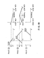
- Another conventional system for inputting and outputting the image, which has been improved to solve the shortcomings mentioned above, is shown in FIG.1 and described in Japanese Patent Laid-open No.11062/1984. According to the conventional system shown in FIG.1, a color original 2 applied on a
rotary input drum 1 is outputted as an image on a recording material, for example, acolor paper 11 pasted on anoutput drum 10, which rotating according to the image information inputted through adigitizer 14 of an image input apparatus. In the image input/output system above, the color original 2 is color-scanned by areading head 21 in order to color separate and the color separation signal CS obtained is inputted to a logarithmic converting circuit 3. The color separation signal CS is converted to density signals DN through the logarithmic converting circuit 3 and then it is converted to digital density signal DS by an A/D converter 4. The digital density signal DS is inputted to asignal processing section 5 and amicroprocessor 12. In thesignal processing section 5, a color correction processing, a sharpness emphasis, and a gradation conversion are carried out, the color-processed image information DSA is converted to analog signals through a D/A converter 6 and inputted to amodulator 8 installed in a laser beam printer in order to modulate a laser beam emitted from alaser oscillator 7 and expose thecolor paper 11 pasted on theoutput drum 10 by means of an output head (not shown). - While, it is necessary to install in the system a
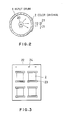
console 16 provided with a keyboard through which data and commands are inputted. According to the conventional system, the data and the commands or instruction inputted through theconsole 16 are inputted to thecomputer 13 for processing these data and commands outputting information and the information is displayed on an interactivegraphic display 15. Thecomputer 13 is connected to amicroprocessor 12 of a lower-level system, themicroprocessor 12 receives the density signal DS outputted from the A/D converter 4 and further connected to thesignal processing section 5 in order to function the process. Thecomputer 13 and themicroprocessor 12 constructs a computer system and the system displays the instruction for the operator and the like on thegraphic display 15 according to the instored programs. The positions of theinput drum 1 and theoutput drum 10 are respectively detected by detectors (not shown) and the positional informations are inputted into themotion control section 9. Themicroprocessor 12 is adapted to be connected to themotion control section 5 so as to relatively drive and control the positional relationship of theseinput drum 1 and theoutput drum 10. Thedigitizer 14 has an original coordinate and X-Y axes of it's own, and the origin coordinate can be easily moved to any points and the X-Y axes can easily rotate by processing the signal. The corresponding relationship between the image position on theinput drum 1 and thedigitizer 14 is determined by installing guides, such as pins at the common plural position. Thedigitizer 14 is connected to thecomputer 13 to which the shape of the images and desired positional coordinates are inputted. - In the image input/output system shown in FIG.1, it is noted that the color original 2 is pasted directly to the smooth outer face of the
cylindrical input drum 1 as shown in FIG.2, which drum being made of acrylic resins, glass or the like. Theinput drum 1 has alight source 20 therein and the light source illuminates the color original 2 and the light beam LT passes through the cylindrical wall of theinput drum 1. Thereading head 21 situated outside of theinput drum 1 receives the passed light beam LT, so that the image of the color original 2 is inputted to thereading head 21. In the condition, if there is a space or gap of a length about wave-length of the beam of thelight source 20 between the color original 2 and theinput drum 1, a Newton ring (interface fringe) is formed by an interference phenomenon happened on the surface between the rear face of the color original 2 and the front face of theinput drum 1, so that the Newton ring is appeared on the color original 2 in the shape of stripes or density irregularity, deteriorating the quality of the original considerably. - According to the conventional method, in order to prevent the interference stripes from forming, super fine particle powder has been scattered or applied between the color original 2 and the
input drum 1 or filler agent is coated on thecylindrical drum 1. However, the fine particle powder has disadvantages, such as the outlines of particles are clearly seen when the multiplication of the image is high and the powder is troublesome to handle, and the filling agent has shortcomings, such as the application or coating and removing or wiping-out of the agent is very difficult to do them completely. - It is known that the image input/output system of the prior art receives an image information on the original film and the like, functions to enlarge or reduce the image, and outputs the image with an any layout on the display or some output device. The image input/output system must know or determine the coordinates of the color original 2 on the
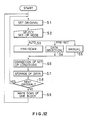
input drum 1 in order to layout the image during the reading of the original as shown in FIG.2. Consequently, as shown in FIG. 3, the the color original 2 is pasted on theoriginal pasting base 22 of transparent and square-shaped sheet bypasting tapes 23. Positioningholes 24 formed in the originalpasting base sheet 22 are fitted onto the corresponding pins of the digitizer so as to input the coordinates of the particular or necessary portion of the color original 2 to the image input/output system. Then, thepositioning holes 24 of the originalpasting base sheet 22 are fitted securely onto thecorresponding pins 25 planted on theinput drum 1 as shown in FIG.4. As next step, thelight source 20 in the interior of theinput drum 1 as shown in FIG.2 irradiates the color original 2 and thereading head 21 receives the passed light beam LT through the drum wall and the color original 2, so that the image of the color original 2 is inputted to thereading head 21. The inputted image is compared to the coordinates inputted by the digitizer so as to layout the image. - Furthermore, the conventional image input/output system necessitates expert operators determining and setting the separating conditions and signal processing conditions and the time used to the condition determination is considerably longer than that of the system for which time the system actually processes the separating operation and the signal processing. Then, operation of the conventional image input/output system for setting the parameter is complicated, so that psychological burden upon the operator is very heavy. For example, Japanese Patent Laid-open No. 37878/1985 specification describes an automatic setting system of a gradation conversion table of the image input/output system, which system determines directly solely the setting condition from the inputted character values. It is noted that any macro-sized information in the original fails to have a rule and accordingly the presumption precision of the parameter has a limit. Another example of Japanese Patent Laid-open No.111570/1987 describes an automatic setting process of signal processing condition, an operation of the condition setting of which process depends on selective appointment of the basis of the subjective judgement of the operator for the automatic setting machine, so that the operation has shortcomings, such as uneffectiveness and non-correctness.
- Generally, conventional color scanners are of drum scanner type in which an original to be read and outputted is pasted on an input drum by means of an pasting tapes or the like for enabling reading. More specifically, as shown in FIG.5, the conventional color scanner has an
input section 30 which scans and reads a color reversal film original so as to produce a color separation signal CS composed of color of red (R), green (G) and blue (B). The color separation signal CS is delivered to animage processing section 40A which produces a dot % signal DS and delivers it to anoutput section 50, whereby a halftone film compose of four color images of cyan (C), magenta (M), yellow (Y) and black (K) is obtained from theoutput section 50. Theimage processing section 40A is arranged such that an operator can externally and manually input a set-up condition SU which directly viewing the original or monitoring the image of the original displaying on a display device. - As stated above, the conventional color scanner is constructed such that the operator determines and inputs the set-up condition SU for each of the originls. The input is conducted by manipulating dials, keys or the like. In addition, the conventional color scanner of drum-scan type requires a troublesome work for setting the original on the cylinder or drum. In addition, replacement of the cylinder is necessary when the magnification has to be changed largely. Moreover, the setting of the original on the
input section 30 also is conducted manually. Thus, the conventional color scanner was quite far from full-automation of the image forming process. - This invention has been invented under the situation above and an object of the invention is to provide a color scanner of a plane scanning (flat bed) type and an automatic setting method for the processing condition of the apparatus by automatically analyzing the original data and setting the image processing conditions without any troublesome operation and troublesome pasting of the original, in which apparatus the necessary supplemental informations are inputted when the certainty factor is low.
- Another object of this invention is to provide a flat bed type color scanner in which the image processing conditions are effectively set on the basis of analysis of the original.
- Still another object of this invention is to provide a flat bed type color scanner in which a series of operations excepting the setting of separating condition on the original are fully automated so as to improve the efficiency of the scanning process, thereby to overcome the above-described problem of the prior art.
- According to one aspect of this invention, for achieving the objects described above, there is provided a color scanner comprising an image reading means for reading an original stored in an original cassette by carrying out of a rough-scanning or main scanning, a signal processing means for signal-processing the main scanning data of said original, which the main scanning data obtained by said image reading means, an operating setting means for obtaining characteristic values of said original on the basis of rough-scanning data obtained by said rough-scanning, calculating original classification informations on the basis of the characteristic values, setting signal processing conditions for said signal processing means, and outputting a certainty factor, an input means for inputting necessary supplemental informations when said certainty factor is low, and a recording means for recording the image on the basis of the output of the signal processing means.
- According to another aspect of this invention, there is provided an automatic setting method of signal processing conditions, in a color scanner for reading an original stored in an original cassette and signal-processing the signal obtained by the reading above in order to record the image, comprising the steps of obtaining characteristic values of said original on rough-scanning data of the original, calculating the original classification informations on the basis of the characteristics values, determining a certainty factor, automatically setting parameters of said signal processing on the basis of the original classification informations, and inputting necessary supplemental informations when the certainty factor is low.
- Further, according to still another aspect of this invention, there is provided a color scanner comprising: an input section for scanning and reading an original while conducting color separation; an original storage and transporting section having an original storage portion, said original storing and transporoting section being capable of automatically transporoting said original from said storage portion to said input section; an image processing section for performing image processing on the basis of color separation signals from said input section so as to produce halftone signals; an output section for producing and outputting a halftone film from said halftone signals; and automatic condition setting section for determining signal processing conditions on the basis of rough-scan data from said image processing section and for setting set-up parameters of said image processing section.
- The nature, principle and utility of the invention will become more apparent from the following detailed description when read in conjunction with the accompanying drawings.
- In the accompanying drawings:
- FIG.1 is a block diagram showing an example of the conventional image input/output system;
- FIGs.2 to 4 respectively show the application of the color originals to the input drum;
- FIG.5 is a block diagram showing the construction of a conventional color scanner;
- FIG.6 is an appearance view of one of the embodiments of the color scanner according to this invention;
- FIG.7 is a constructive view of an example of the original table of this invention;
- FIG.8 is an optical system of the image input section;
- FIG.9 is a view showing a linear scanning by means of the relation between the light source and the original;
- FIG.10 is a constructional view of one of the embodiments of the output unit;
- FIG.11 is a block diagram to show the circuitry of the color scanner according to this invention;
- FIG.12 is a flow chart to show the operation of this invention;
- FIG.13 is a flow chart showing an example of the signal processing condition setting method of this invention;
- FIG.14 is a flow chart to show a part of the flow chart of FIG.13;
- FIGs.15A and 15B respectively show the accumulative histogram and the characteristic relative to the histogram.
- FIG.16 shows an example of the density data;
- FIGs.17 and 18 are examples of the membership function, respectively;
- FIGs.19 and 20 are diagrams for explaining the calculation of certainty factor in the fuzzy reasoning, respectively;
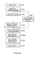
- FIG.21 is a flow chart showing another example of the signal processing condition setting method of this invention;
- FIG.22 is a flow chart to show a part of the flow chart of FIG.21;
- FIG.23 is an illustration of appearance of an the embodiment of this invention;
- FIG.24 is an illustration of appearance of a storage and transportation unit;
- FIG.25 is an illustration of internal structure of an auto-feeder;
- FIG.26 is an illustration of the construction of storage box;
- FIG.27 is a plane view of the auto-feeder;
- FIG.28 is an illustration of an arrangement for feeding an original cassette into the input unit of the color scanner;
- FIG.29 is an illustration of construction of an original table.
- FIG.30 is a block diagram to illustrate the construction of another embodiment of this invention scanner;
- FIG.31 is a block diagram showing the construction of an image processing section used in the embodiment of this invention; and
- FIGs.32 and 33 are flow charts to illustrate the operation of the described embodiment, respectively.
- FIG.6 shows an external appearance of the color scanner according to this invention. The system has a
scanner 100 for reading an original image placed at the center of the structure, amonitor 200 for color-displaying the read image and the image to be outputted placed on thescanner 100, and amain desk 101 on which thescanner 100 is mounted. Thescanner 100 has an original table 110 at the front thereof, in which table the original cassette which will be explained lately is charged. The original table 110 slides into the installation in order to line-scanning the color originals. Aninput unit 300 into which the necessary instructions and the like are inputted by an operator is placed on themain desk 101. A signal processing section (color processor) 400 for processing the image data read from the original and calculating the necessary calculation in order to output the separation signals of C, M, Y and Black (K) is placed under themain desk 101. Theinput unit 300 has akeybord 301 through which the operator inputs the data and instruction and aCRT 302 for displaying the necessary informations to operating the system. Anoutput unit 500 situated in side by side relation at themain desk 101 outputs an halftoned film on the basis of the data processed by thesignal processing section 400. The automatic developingunit 600 for developing the film for separation making outputted from theoutput unit 500 is provided. It is understood that the shape and arrangement of respective units above are not limited to these shown in FIG.6. - FIG.7 shows the construction of the original table 110 of the
scanner 100. The original table 110 of a box-like is adapted to be scanned along the auxiliary scanning direction by means of a moving member 111 connected to the construction of the original table 110, awire 112 connected to the moving member 111, and amotor 113. There is arotary base receiver 115 driven along the arrow shown by a motor 114 in the interior of the original table 110 and there is acassette receiver 103 to which theoriginal cassette 102 is applied at the center of therotary base receiver 115. Therotary base receiver 115 is adapted wholly to carry out a scanning operation along the trimming direction shown by a movingmember 116 connected to the structure of therotary base receiver 115 and awire 117 joined to the movingmember 116 and amotor 118. It is possible to carry out scanning operations of the movingmembers 111 and 116 by means of another mechanism, such as a screw bar and nuts. Acorrection region 104 for reading the magnification adjusting chart when the image reading starts so as to adjust the optical system is situated on the surface of the original table 110 at the end of the auxiliary scanning operation. - FIG.8 depicts an optical system of the input portion of the
scanner 100. As shown theoriginal cassette 102 received in thecassette receiver 103 is illuminated by a linear-shaped aperturetype fluorescent lamp 121 arranged at a lower position. In theoriginal cassette 102, acolor original 120, for example, a color reversal film and the like is fitted or stored and thecolor original 120 is sandwiched by a pair of anti-reflection typetransparent glasses original cassette 102 is inputted to animage focusing lens 124 of a magnification set by theinput section 300 and also inputted to acolor separating prism 125 connected to be upper portion of theimage focusing lens 124, separating into the three primary colors of Red, Green and Blue. These three primary colors separated are inputted to imagesensors image focusing lenses 124 of different magnification appointed are prepared on a turret mechanism and any lens can be used easily. FIG.9 shows a line-scanning relation between thefluorescent lamp 121 and thecolor original 120. The whole image is read when the linear shapemain scanning line 120A moves along the auxiliary scanning direction. The input optical system described above can roughly scan the color original 120 before the main scannign thereof. - FIG.10 shows roughly the construction of the
output unit 500, which functions as a slave of thesignal processing section 400, carrying out a fixed control sequence on the command transferred by RS-232C and returning the resultant condition to ahost machine CPU 401 of thesignal processing section 400. That is, when a status check signal is sent from theCPU 401 to theoutput unit 500, theoutput unit 500 outputs a "READY" signal when it is exposable condition and returns a "OK" signal responsing to exposure preparation inquiry signals sent from theCPU 401 in order to carry out the exposure. The image signal sent from thesignal processing section 400 is halftoned in ahalftoning circuit 531 which will be described later so as to be converted to ON/OFF signals. Thus, the ON/OFF signals are exposed on aphotosensitive material 503 by alaser beam 502 emitted from the laser shapinglight source 501 consisiting of laser diodes. The main scanning of thelaser beam 502 is done by usingresonant scanner 504 and the mainly scanned laser beam exposes thephotosensitive material 503 rounded around theauxiliary scanning drum 510 throughfϑ lens 505 and amirror 506. Theauxiliary scanning drum 510 carries out an auxiliary scanning relative to thelaser beam 502 and theauxiliary scanning drum 510 is driven by a DC servo-motor controlled on PLL (Phase Locked Loop). Thephotosensitive material 503 is stored in aphotosensitive magazine 511 and transferred around theauxiliary scanning drum 510 through a transfer roller. Then, theexposure material 503 is cut by acutter 512 at a predetermined length and discharged out of theoutput unit 500. - The halftone processing of the image carried on by the
halftoning circuit 531 is digitally done by sequentially comparing the image signal to a dot (halftone data) of the thershold values of eight bits. The standard halftone data are stored in an ROM and other halftone data are stored in an optional floppy disc. As required, the halftone data is loaded in the system from the optional floppy disc. Theoutput unit 500 is always a slave of thesignal processing section 400, only processes the commands sent from the RS-232C at fixed sequence and returns the resultant condition to thesignal processing section 400. Theoutput unit 500 can not activate commu nication by oneself. - Because of such construction of the
output unit 500, a series of sequential processings during an exposing are carried out when thesignal processing solution 400 controls theoutput unit 500 through a communication. Theoutput unit 500 further has functions which are initialized through a panel of thesignal processing section 400, such as initial loading, cleaning, cutting, and a set of the remaining photosensitive material register. The initial loading means feeding of thephotosensitive material 503 by the predetermined length so as to cut or remove the exposed portion of the photosensitive material. When thephotosensitive material magazine 511 is loaded or a material-jamming is happened and the cover is open, attaining the initial condition. The cleaning means an operation, in which a predetermined volume of thephotosensitive material 503 is drawn out and cut, sent to the automatic developingunit 600 so as to operate the automatic deveroper supplying developing liquid, a fixing liquid, and washing water. The cutting is an operation in which thephotosensitive material 503 drawn for exposing is cut and discharged. In the setting of the remained photosensitive material register, the remained volume of the exposure material is set when thephotosensitive material magazine 511 is loaded, the set volume is reduced at each cutting and discharging step, and the resultant is displayed. - The inner construction of the color scanner is shown in FIG.11, in the system the RGB image signals PS outputted from the
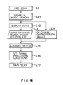
image sensors scanner 100 are inputted to thesignal processing section 400. The image signals PS consist of the rough-scan data obtained by a rough-scanning or a main scan data obtained by a main scanning, and these scan data respectively are digitized and inputted to thesignal processing section 400. Thesignal processing section 400 has a CPU ( host computer ) 401 for controlling the whole functions of thesignal processing section 400, which theCPU 401 functioning as necessary an END ( Equivalent Neutral Density )conversion 402, acolor correction 403, amagnification 404,sharpness emphasis 405, agradation conversion 406 andblack printer generation 407. Thesignal processing section 400 has as shown in FIG.11 afloppy disc 410 and ahard disc 411 connected thereto through which discs the necessary data is read and stored. Animage memory 420 is operatively connected to thesignal processing section 400 so as to tempo rarily store the rough-scan data and amouse 421 is so connected as to input necessary instructive informations to thesignal processing section 400. Themonitor 200 and theinput unit 300 are connected to thesignal processing section 400 so as to send separation making signals of four colors of C, M, Y, K (black) signalized to theoutput unit 500, consequently the laser shapinglight source 501 emits thelaser beam 502 through thehalftoning circuit 531 and thedrive circuit 532. Thehalftoning circuit 531 and thedrive circuit 532 are adapted to be controlled by theCPU 530. Thesignal processing section 400 reads the rough-scan data in theimage memory 420 to calculate the characteristic values of an accumulative histogram and the like, processes the original classification information, such as over-exposure/under-exposure and the like on the basis of the characteristic values above, automatically sets parameters of the processing condition, and outputs a certainty factor. It is possible to input the scanning informations, such as a trimming range, a magnification, output line number, a halftone angle and the like and start/stop commands for sequence-controlling through thekeyboard 301 and themouse 421. - The operation of the construction of the
signal processing section 400 will be explained with reference to flow charts. - First, the
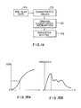
original cassette 102 is set to thescanner 100 by inserting theoriginal cassette 102 into the cassette receiver 103 (Step S1) and designating the condition set-up mode ( automatic, pre-set, manual ) by the operator operating thekeyboard 301 of the input unit 300 (Step S2). According to this invention, when an automatic mode is selected, a prescanning for condition-setting is carried out by a rough-scanning (Step S3). When the pre-set mode is selected, the previously stored condition data is outputted (Step S4.) In case that the manual mode is selected, the condition data is inputted manually through the keyboard 301 (Step S5). The condition data are coefficient values for color-correction, sharpness coefficients for sharpness emphasis inclination of gradation change conversion and so on. The automatic setting by the rough-scanning will be explained. Thus set signal processing conditions are displayed together with the certainty factor on theCRT 302. When the signal processing conditions have low certainty factor relative to the set conditions and some correction is necessary, the operator corrects manually the setting parameters (Step S6) and the condition data is stored (Step S7). - The automatic setting of the signal processing conditions by the pre-scanning will be explained with reference to FIGs.13 and 14. The pre-scan data PD obtained by the pre-scanning is stored in the image memory 420 (Step S31) and the image of the particular original is displayed on the monitor 200 (Step S32) so as to do a calculation of the characteristic values CR (Step S34). Various characteristic values CR consist of the density (level) at any percent of the accumulative histogram for each color of RGB, the level value of the accumulative histogram for each color in respective region of display frame divided ( for example, 1/4, 1/8), mean density for each color of RGB, and the maximum peak density of the histogram for each color. FIG.15A shows an example of the accumulative histogram and how to obtain the density at any percent of the accumulative histogram. FIG.15B shows an example of the histogram and how to obtain the maximum peak density of the histogram. The original classification informations OC are calculated according to the rule describing the relation between the characteristic values CR and the original character. For example, the original classification informations OC are obtained according to the following rule.
- As shown in FIG.16, the rough-scan data is the density data Pij of M x N picture elements. The mean value x as the characteristic value CR is determined in the following equation.
x = ΣPij/MN (1) - When the key of the original is fuzzy-reasoned as the original classification informations OC, you must follow to the following rules ⓐ to ⓒ with the attribute determination name y of the original key.
- Rule ⓐ: If x = low, then y = high key.
- Rule ⓑ: If x = middle, then y = normal.
- Rule ⓒ: If x = high, then y = low key.
- The underlined words in these rules ⓐ to ⓒ above mean fuzzy variables. The functions shown in FIG.17 are used as membership functions to be used in the If-portions and the functions shown in FIG.8 are used as membership functions to be used in then-portions in the rules ⓐ to ⓒ above. Presupposing that x = x₀ is inputted, the rules ⓐ to ⓒ become these shown in FIG.19. The grade of the original key y₁ (high key) in the rule ⓐ is w₁, the grade of the original key y₂ in the rule ⓑ is w₂, and it is not suitable or not conformity of the original key y₃ (low key) as apparent from the rule ⓒ. The whole outputs y of these rules ⓐ to ⓒ are obtained by weighting the outputs y₁ to y₃ from each rule with the grades w₁ to w₃. Accordingly, the whole outputs y is a weighted mean value as shown below.
y = (w₁·y₁ + w₂·y₂)/(w₁ + w₂) (2)
This equation is generalized by a rule number n, obtaining the following equation.


- It is possible that the membership functions in the then-portion don't have actually the shapes of function as shown in FIG.20. It is sufficient that the membership functions clarify the grades of y₁, y₂ in short.
- As described above, the original key is induced according to this invention by using the fuzzy reasoning process and the certainty factory β of the reasoning is determined, outputting the certainty factory. When the certainty factory β is lower than a predetermined value ( for example, 0.4 ), the operator will input a supplemental information of the high, low or normal key. When any supplemental information is not inputted, the fuzzy reasoning is done. When the supplemental information is inputted, the fuzzy reasoning doesn't carry out. Accordingly, the informatian obtained after the original is rightly judged can be inputted.
- Various conditions of exposure conditions of under/over, existence of highlight point, picuter pattern, existence of skin color, color fogging and the like can be determined by using the fuzzy reasoning. For example, with reference to the original exposure condition of the minimum density Dmin shown in FIG.15B. the fuzzy reasoning shown below can be used. If Dmin = low, then y = over-exposure. If Dmin = middle, then y = normal-exposure, and If Dmin = high, then y = under-exposure.
- In the automatic setting method of the signal processing conditions according to this invention, the operator inputs the trimming range and so on through the
input unit 300 while watching the image display on the monitor 200 (Step S33), sets the parameters by using the original classification informations OC obtained as described above (Step S35), sets the signal processing conditions (Step S36), and then carry out the main scanning(Step S37). The set-up parameters are the highlight/shadow point density of the gradation conversion curve, the shape of the curve, the sharpness emphasis coefficients, the color correction coefficients and the like. - That is, the image of the
color original 120 of theoriginal cassette 102 loaded is read by thescanner 100 after the pre-processing mentioned above. During the reading operation, theoriginal cassette 102 rotates by therotary base receiver 115, moves along the trimming direction by means of the movingmember 116 and along the auxiliary scanning direction by means of another moving member 111 in order to mainly scan the region of theline 120A as shown in FIG.9. The light beam irradiated from thefluorescent lamp 121 and passed through theoriginal cassette 102 is inputted to the focusinglens 124 and resolved separated into the colors through thecolor separating prism 125, focusing each beam of colors onrespective image sensors image sensors signal processing section 400, in which each processing of theEND conversion 402, thecolor correction 403, themagnification 404, thesharpness emphasis 405, thegradation conversion 406, theblack printer generation 407 is processed at the predetermined conditions. The color correction is done by the method, for example, described in Japanese Patent Application Laid-open No.178355/1983 and the sharpness emphasis is carried out by the method described, for example, in the specification of Japanese Patent Application Laid-open No.54570/1985. It is possible to use the method described in Japanese Patent Application Laid-open No.11062/1984 in order to do these processes above including the END conversion and the gradation conversion. The image formed by the generated image signals of C,M,Y,K is displayed on themonitor 200 and it is possible to control the color tone and so on through thekeyboard 301 while watching the displayed image so as to make the display a disired one. - The output signals of C,M,Y,K. obtained in the
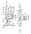
signal processing section 400 are sent to theoutput unit 500, halftone-processed by thehalftone circuit 531 of theoutput unit 500 and sent thedrive circuit 531 of theoutput unit 500 and sent to thedrive circuit 531 of the laser shapinglight source 501, and the output signals are emitted in the shape of binary signal of the halftone output. Thelaser beam 502 emitted from thelight source 502 is inputted to theresonant scanner 504 and thefϑ lens 505, reflected on themirror 506, and thephotosensitive material 503 on theauxiliary scanning drum 510. Thephotosensitive material 503 exposed is cut at its predetermined length by thecutter 512, sent to the developingunit 600 and develops the photosensitive material processing a separation of four colors of C,M,Y and K. - Further, according to this invention, as shown in FIG.30 corresponding to FIG.5 an original such as a color reversal film is scanned in an
input section 30 so as to be color-separated into picture components of three colors R, G and B, and the color separation signal having these three components R,G and B is inputted to animage processing section 40. Theimage processing section 40 produces rough-scan data (LS) in response to a rough-scan (pre-scan) and delivers it to an automaticcondition setting section 60. The automaticcondition setting section 60 produce an original classification informations OC and delivers it to theimage processing section 40 so as to automatically set set-up parameters necessary for the image processing. Data other than the processing conditions required by theimage processing section 40, i.e., separation conditions SU for the original, are manually inputted by an operator. - Thus, in the color scanner of this invention, the processing conditions are automatically determined in the automatic
condition setting section 60, so as to automatically set the set-up parameters necessary for the image processing. Thus, the operator is required only to input the separating conditions ( magnification, output size, trimming range, line number of scanning, discrimination between the negative and positive modes and so on ) SU, and all other conditions are set automatically so as to improve the efficiency of the scanning process. - The original is automatically transported from the storage section to the
input section 30 through an original cassette and the original after the reading in theinput section 30 is automatically returned to the storage section, whereby the reading of the original and the output of the original is fully automated. - Flow charts of FIGs.21 and 22 show an example of the operation in the case of inputting finishing information in correspondence to FIG.33 and 14, respectively. In this case, the inputting step S35A is inserted as shown in FIG.21 and the finishing information includes gray point, brightness/darkness, preference, tone, type of picture, or the like. Further, the operation of the original classification informations OC is performed by fuzzy reasoning described hereinafter.
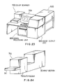
- FIG.23 illustrates an appearance of the
color scanner 700 in accordance with this invention. Thecolor scanner 700 is placed on a desk which also carries anoperation panel 701 having a display unit. Asignal processing unit 800 is disposed under the desk beneath theoperation panel 701. Animage output unit 500 as shown in FIG.10 and an automatic developingunit 600 for developing the images on the output film are disposed in the vicinity of thesignal processing unit 800. FIG.24 shows the manner in which theinput section 30 of thecolor scanner 700 is combined with an original cassette storage andtransportation unit 710 which stores and transports the original cassettes holding the originals such as a color reversal film. The storage and transportation unit 107 includes acassette base 711 for mounting an original cassette and anauto feeder 712 for storing and transporting a multiplicity of original cassettes. - FIG.25 is a perspective view illustrating the internal construction of the
auto feeder 712. Theauto feeder 712 has a storage box 726 for storing a multiplicitty of rectangular parallelepipedoriginal cassettes 790 stacked one on another. Entrances/exits 721 are formed in the front surface of thestorage box 720 in stages at a predetermined interval. A plurality ofcassette driving windows 722 are formed in one side of thestorage box 720 so that theoriginal cassettes 790 can be driven out of and into thestorage box 720 as indicated by arrows M and N by means oftransportation rollers 723 andelastic belts 724 which rotate and run in pressure contact with the cassettes.Support plates 725A to 725D and 726A to 726D are provided on the top panel and the bottom panel of thestorage box 720 at four corners. Circular holes are formed in diagonally opposing pairs ofsupport plates round bars support plates rods Rollers 731 and 732 are respectively secured to lower end portions of thescrew rods belts rollers 731 and 732 and, hence, thescrew rods storage box 720 to move up and down. More specifically, the motor 735 has a motor shaft 736 to which are fixeddrive rollers belt 733 is stretched between therollers 738 and 731, while thebelt 734 is stretched between therollers storage box 720 raised to the uppermost position and anoriginal cassette 790 being extracted from the lower most entrance/exit 721. - A
cassette drive base 740 is disposed on thestorage box 720 at a position adjacent to thecassette driving window 722. As shown in detail in FIG.27, amotor 742 and asolenoid 741 are carried by thecassette drive base 740. At the same time, aswivel plate 743 is provided on thecassette drive base 740 for swiveling motion about anaxis 741A in the directions of arrows P and Q. Thesolenoid 741 has aplunger 741A which is connected to one end of aswivel plate 743, while atransportation roller 723 for driving theoriginal cassette 790 into and out of thestorage box 720 is secured to the other end of theswivel plate 743. Anelastic belt 744 is stretched between thetrnsportation roller 723 andshaft 745 of themotor 742. Theswivel plate 743 is normally biased for rotation in the direction of the arrow Q about thepivot point 743A by, for example, a spring which is not shown. However, when thesolenoid 741 is energized, theplunger 741A is activated to cause theswivel plate 743 to rotate in the direction of the arrowP. Drive plates 746 are disposed on the opposite side of thecassette driving windows 722. Thedrive plate 746 an array offree guide rollers 747, so thatoriginal cassette 790 is allowed to smoothly moved into and out of thestorage cassette 720. - Referring to FIG.26 showing the internal structure of the
storage box 720,shelves storage box 720. Theoriginal cassettes 790 are slidably held on theseshelves storage box 720. FIG.28 schematically shows the internal structures of thecassette transportation mechanism 750 and aninput section 30 of thecolor scanner 700. The arrangement is such that anoriginal cassette 790 extracted from the auto-feeder 712 is transported by thecassette transporting mechanism 750 such as a belt conveyor and is moved on to afeed passage 751 through an entrance/exit 752 of theinput section 30. Feed rollers 753 to 755 are arranged at both sides of thefeed passage 751. These feed rollers 753 to 755 are connected to driverollers 753A to 755A through drive shafts. Abelt 756 is wound around thesedrive rollers 753A to 755A and adrive shaft 757 of amotor 758, so that the feed rollers 753 to 755 are rotated by themotor 758 so to guide and feed theoriginal cassette 790 along thefeed passage 751. The thus fedoriginal cassette 790 is moved into an original table 900 the detail of which will be described with reference to FIG.7. - FIG.29 illustrates the construction of original table 900 of an image reading section which handles the above-mentioned the
original cassette 790. The whole of the housing type original table 900 is capable of moving in the direction of an auxiliary scanning by the action of a movingmember 901 which is connected to the original table 900 and which is driven by amotor 903 through awire 902. A turn-table 911 is provided in the original table 900 so as to be rotated in the directions of arrows by amotor 911. Acassette receiving recess 912 for receiving theoriginal cassette 790 is provided in the center of the turn table 911. The turn table 911 has a moving late to which is connected a movingmember 920 which in turn is connected to amotor 922 through awire 921 so that the whole turn-table 911 is capable of moving in the trimming directions by the force produced by themotor 922. A correctingregion 904, which is provided on upper leading end of the original table 900 as viewed in the direction of the auxiliary scanning, includes a magnification adjusting chart which is read in advance of reading of the image so as to allow adjustment of an optical system.Guide rollers 931 to 933 and 934 to 936 are arrayed on the turn-table 911 at both sides of theoriginal cassette 790. Astopper 930 serving as a locating member for locating theoriginal cassette 790 is disposed near one ends of the tow of theguide rollers 931 to 933 and 934 to 936. - FIG.31 is a block diagram showing the detail of the
image processing section 40 in thesignal processing unit 800. The analog color separation signal CS having tri-color components R,G,B is converted into a digital signal by an A/D converter 41 and is then inputted to a densityconversion calibaration circuit 42. Then, color signal of C, M and Y are delivered to an END ( Equivalent Neutral Density )conversion circuit 43 so as to be END-converted while maintaining gray balance. The END-converted signals are then inputted to apicture adjustment 44. Thepicture adjustment 44 sets the highlight and shadow points of the signal to predetermined positions, and the thus picture-adjusted signals are inputted to a color correction circuit 35, so that the color signals after the color correction are gradation-converted by a gradation conversion table 46. The gradation-converted signals are then inputted to a Kprinter generating circuit 47 which generates a K (black)-printer in addition to C, M and Y-colors, so as to be converted into C,M,Y and K colors. These color signals are inputted to a magnification (enlargement and reduction) adjustingcircuit 48 for a magnification conversion and then inputted to asharpness emphasis circuit 49 which stresses the sharpness, whereby a halftone dot % signal DS is obtained. The above-mentionedEND conversion circuirt 43 receives END matrix data which forms a matrix used in the END conversion, while thepicture adjustment 44 receives set density values of the highlight and shadow points so that the brightness level curve is set in thepicture adjustment 44. On the other hand, thecolor correction circuit 45 receives color correction coefficients so that parameters for color correction are set in thecolor correction circuit 45. A gradation curve has been inputted to the gradation conversion table 46. A K-printer curve, a K-printer intensity data and an UCR ( Under Color Removal ) intensity data have been inputted to the K-printer generating circuit 47. A USM ( Unsharp Mask) size intensity data has been inputted to thesharpness emphasis circuit 49. - The
input section 30 has a reading mechanism identical with the construction shown in FIGs.8 and 9 and further theoutput section 50 also has an output unit as shown in FIG.10. - The operation of this embodiment will be described with reference to a flow chart shown in FIG.32.
- An original is set in the original cassette 790 (Step S40) , and the separation conditions SU such as the magnification, trimming range, negative/positive selection and so forth are inputted to the
image processing section 40 from an external set-up station (not shown), the inputted conditions being stored in a memory (not shown) in relation to the cassette numbers (Step S41). The operation for inputting the separation conditions SU is sequentially conducted until the original for all originals (Step S42). Then, theoriginal cassette 790 is set in thestorage box 720 of theauto feeder 712 of the storage and transportingunit 710 shown in FIGs.25 to 28, in a manner shown in FIG.26 (Step S43). The image reading operation is then started in response to a start signal which is provided when, for example, a start button is pushed by an operator (Step S44). - A description will be given of the manner in which the
original cassette 790 is transported from the auto-feeder 712 of the storage andtransportation unit 710 to thecolor scanner 700. When the desired original is appointed through theoperation panel 701, theoriginal cassette 790 containing the original is retrieved. As the motor 735 is driven, therollers 731 and 732 are rotated so that thescrew rods storage box 720 up and down. In this state, thesolenoid 741 has been energized so as to cause theswivel plate 743 in the direction of the arrow P about thepivot point 743A, so that theroller 723 is kept away from thecassette drive window 722 and the drivingplate 746 opposite to theroller 723 also is kept away from thestorage box 720 so as to allow thestorage box 720 to smoothly move up and down. When thestorage box 720 has reached a predetermined set position, the motor 735 is stopped and the solenoid is deenergized so that theswivel plate 743 is rotated in the direction of the arrow Q by the force of, for example, spring, so that theroller 723 is pressed onto one side surface of theoriginal cassette 790 through thecassette driving window 722. This in turn causes the other side surface of theoriginal cassette 790 to be pressed against theguide rollers 747 on the drivingplate 746. Then, themotor 742 operates in the direction of the arrow S so that theoriginal cassette 790 is moved out of thestorage box 720 through the entrance/exit 721 as indicated by the arrow M. - The
original cassette 790 thus driven out of the auto-feeder 712 is sent to thefeed passage 751 in theinput section 30 of thecolor scanner 700 by means of thecassette transportation mechanism 750 and is fed into the original table 900 while being guided at its both sides by the feed rollers 753 to 755 driven by themotor 758. Theoriginal cassette 790 then slides on the movingplate 923 of the original table 900 and advances until it is stopped by thestopper 930 while being guided by theguide rollers 931 to 933 and 934 to 936, and is loaded in thecassette receiving recess 912. Then, the separation conditions Su corresponding to the number n of the cassette set in thescanner 700 are read from the memory (Step S45), and theinput section 30 conducts a rough scan (pre-scan) of the original in the original cassette 790 (Step S46) The rough scan data L.S thus obtained is inputted to the automaticcondition setting unit 60 through theimage processing unit 40, and the following process in executed. - Namely, the signal processing conditions are automatically set in accordance with the result of the pre-scan in a manner which will be des cribed with reference to FIGs.33 and 14. The image data PD obtained through the raugh scan (Step S51) is stored in the image memory (Step S52) and the image of the original is displayed on a monitor such as a CRT (Step S53). At the same time, characteristic values CR are computed (Step S55). The characteristic values CR included levels of density at any percentage (%) of accumulation of the cumulative histograms (for each of the R, G and B colors, the density level at any accumulation percentage of the cumulative histogram of in each section, e.g., 1/4, 1/8 and so forth, of the screen for each of the colors R, G and B, mean density level for each of the colors R, G and B, and the maximum peak density of the histogram for each of the colors R, G an d B. FIG.15B illustrates an example of the cumulative histogram. The density of the cumulative histgram at any desired percentage (%) is obtained in a manner shown in FIG.15A. FIG.15B also shows an example of the histogram. The peak density of the histogram is obtained in a manner shown in FIG.15B. Original classification informations OC are calculated in accordance with a rule which described the relationship between these characteristic values CR and the original characteristics. For instance, the following items of original classification informations OC (① to ⑦ ) are obtained in accordance with the following rules.
- ① If the mean density level is low, then the exposure is extremely over.
- ② If the mean density level is low, then the exposure is over.
- ③ If the mean density level is slightly low, then the exposure is slightly over.
- ④ If the mean density level is medium, then the exposure is normal.
- ⑤ If the mean density level is slightly high, then the exposure is slightly under.
- ⑥ If the mean density level is high, then the exposure is under.
- ⑦ If the mean density level is very high, then the exposure is extremely under.
- Thus, the mean density level range is divided into seven sections designated at ① to ⑦. Thus, the inputted data falls within one of the above-mentioned regions or rules, so that the exposure condition, i.e., whether the exposure is over or under, is determined. Other items of the original classification informations OC are distinction between high-key and low-key, presence or absence of highligh point, pattern, presence or absence of skin color, color fogging, and so forth. The above-mentioned rules of fuzzy reasoning can be applied to each of such other items. Subsequently, parameter setting operation PO is conducted on the basis of the original classification informations OC, in accordance with the following rules.
If the exposure is extremely over, then the density of highlight point is 0.05.
If the exposure is over, then the density of highlight point is 0.10.
If the exposure is slightly over, then the density of highlight point is o.15.
If the exposure is normal, then the density of highlight point is 0.20.
If the exposure is slightly under, then the density of highlight point is 0.30.
If the exposure is under, then the density of highlight point is 0.40.
If the exposure is extremely under, then the density of highlight point is 0.50. - Thus, the density level of the highlight point is determined in accordance with these rules. Highlight point densities also are determined from other characteristic values in the same manner as described above, and the mean value of the highlight point densities determined from different characteristic values is computed. It will be understood that the fuzzy reasoning rule of "If ... , then ... " can be applied also to other items.
- On the other hand, the operator inputs the trimming area (Step S54) through the
operation panel 701 while monitoring the image through the monitor display. Then, the setting of parameters is conducted (Step S56) on the basis of the original classification informations OC obtained in the manner described, followed by setting of the signal processing conditions (Step S57). Then, main scanning is executed by the input unit 30 (Step S58). The data read through the main scan is inputted to theimage processing section 40 and is processed with the parameters which have been set automatically. Examples of the set-up parameters are densities of the high-light and shadow points, shape of the gradation conversion curve, sharpness emphasis coefficients and color correction coefficients. - The halftone dot % signals DS of the colors C, M, Y and K derived from the
image processing section 40 are converted in the output section 50 (the image output unit 500) into halftone films. The halftone films output from theoutput section 50 are delivered to an automatic developingunit 600 so that the color images on the film are developed. The films carrying the developed color images are used as films for making separation of the C, M, Y and K colors. - The
original cassettes 790 after the reading of the original image is extracted from thecassette receiving recess 912 in the original table 900 and is conveyed on the movingplate 923 along the arrays of theguide rollers 931 to 933 and 934 to 936, and is fed back to the cassettetrans portation mechanism 750. The original cassette transported by thecassette transportation mechanism 750 is then moved in the direction of the arrow N through the entrance/exis 721 of thestorage box 720 which has been raised to a predetermined position. Then, themotor 742 is reversed so that theoriginal cassette 790 is stored in thestorage box 720. - According to the color scanner and the automatic setting method of this invention, the original cassette containing the color original can be used without any troublesome operation of applying the originals, so that the whole operation of the setting method of the color scanner can be done without difficulties. Because that the input operation is carried out by a plane scanning, high speed inputting can be attained. Because that the setting of the parameters necessary to the signal processing can be done precisely according to the certainty calculated and the characteristics of the original, it is possible to improve the productivity and workability of the color scanner.
- As will be understood from the foregoing description, in the color scanner of this invention, original classification information is obtained from characteriostic signals representing characteristics of the image obtained through a rough-scan (pre-scan) performed by the input unit, and the image processing conditions are automatically set in accordance with the thus obtained original classification information. Therefore, set-up of image processing conditions, which hitherto have to be conducted by manual work of the operator, can be conducted automatically so as to improve the efficiency of the scanning process, while ensuring objectivity in data setting operation. Furthermore, the storage and transportation of the original (original cassette) are performed fully automatically thus realizing a high-speed operation of the scanner.
- It should be understood that many modifications and adaptations of the invention will become apparent to those skilled in the art and it is intended to encompass such obvious modifications and changes in the scope of the claims appended hereto.
Claims (11)
Applications Claiming Priority (8)
| Application Number | Priority Date | Filing Date | Title |
|---|---|---|---|
| JP63258227A JP2575843B2 (en) | 1988-10-13 | 1988-10-13 | Image input / output system and method for automatically setting signal processing conditions |
| JP258227/88 | 1988-10-13 | ||
| JP258228/88 | 1988-10-13 | ||
| JP63258228A JP2585754B2 (en) | 1988-10-13 | 1988-10-13 | Image input / output system and signal processing condition setting method |
| JP63324424A JPH0817434B2 (en) | 1988-12-22 | 1988-12-22 | Color scanner |
| JP324424/88 | 1988-12-22 | ||
| JP333836/88 | 1988-12-28 | ||
| JP63333836A JP2574021B2 (en) | 1988-12-28 | 1988-12-28 | Image input / output device and method for automatically setting signal processing conditions |
Publications (3)
| Publication Number | Publication Date |
|---|---|
| EP0363988A2 true EP0363988A2 (en) | 1990-04-18 |
| EP0363988A3 EP0363988A3 (en) | 1991-09-11 |
| EP0363988B1 EP0363988B1 (en) | 1996-04-17 |
Family
ID=27478467
Family Applications (1)
| Application Number | Title | Priority Date | Filing Date |
|---|---|---|---|
| EP89119085A Expired - Lifetime EP0363988B1 (en) | 1988-10-13 | 1989-10-13 | Color scanner and automatic setting method |
Country Status (3)
| Country | Link |
|---|---|
| US (1) | US5194946A (en) |
| EP (1) | EP0363988B1 (en) |
| DE (1) | DE68926276T2 (en) |
Cited By (12)
| Publication number | Priority date | Publication date | Assignee | Title |
|---|---|---|---|---|
| EP0479312A2 (en) * | 1990-10-04 | 1992-04-08 | Dainippon Screen Mfg. Co., Ltd. | Method of correcting setup parameter decision characteristics and automatic setup apparatus |
| EP0500112A2 (en) * | 1991-02-21 | 1992-08-26 | Fuji Photo Film Co., Ltd. | Image reading apparatus and method for automatically determining an image area in a larger scanning area |
| EP0502369A3 (en) * | 1991-02-21 | 1993-04-07 | Fuji Photo Film Co., Ltd. | Method of and apparatus for processing image by setting up image processing conditions on the basis of finishing information |
| EP0543602A2 (en) * | 1991-11-19 | 1993-05-26 | Konica Corporation | A digital copying apparatus with a display |
| EP0757473A2 (en) * | 1995-08-01 | 1997-02-05 | Canon Kabushiki Kaisha | Image processing apparatus and method |
| EP0767578A2 (en) * | 1995-10-04 | 1997-04-09 | Canon Kabushiki Kaisha | Image processing method |
| EP0860989A2 (en) * | 1997-02-19 | 1998-08-26 | Canon Kabushiki Kaisha | Scanner device and control method thereof, and image input system |
| US5870491A (en) * | 1989-08-31 | 1999-02-09 | Canon Kabushiki Kaisha | Image processing apparatus which controls processing conditions of an image signal on detected features of the image signal |
| EP0910041A1 (en) * | 1997-10-17 | 1999-04-21 | Eastman Kodak Company | Pathology dependent viewing of processed dental radiographic film |
| US6496280B2 (en) * | 1997-05-12 | 2002-12-17 | Fuji Photo Film Co., Ltd. | Method for image formation and apparatus for development processing |
| US6674444B1 (en) | 1998-09-18 | 2004-01-06 | Mitsubishi Plastics Inc. | Image processing device and method, and recording medium |
| EP1450552A3 (en) * | 2003-02-18 | 2006-08-02 | Fuji Photo Film Co. Ltd. | Data conversion apparatus and data conversion program storage medium |
Families Citing this family (14)
| Publication number | Priority date | Publication date | Assignee | Title |
|---|---|---|---|---|
| US5495349A (en) * | 1990-01-13 | 1996-02-27 | Canon Kabushiki Kaisha | Color image processing apparatus that stores processing parameters by character data |
| US5481623A (en) * | 1990-04-19 | 1996-01-02 | Fuji Photo Film Co., Ltd. | Apparatus for determining an image position on imaging media |
| US5757378A (en) * | 1990-10-13 | 1998-05-26 | Canon Kabushiki Kaisha | Color image processing apparatus |
| US7221475B1 (en) * | 1990-10-13 | 2007-05-22 | Canon Kabushiki Kaisha | Color image processing apparatus |
| US5522657A (en) * | 1993-02-24 | 1996-06-04 | Eastman Kodak Company | Optimization of electronic color printing process functions based on prescan information data |
| US5504583A (en) * | 1993-02-24 | 1996-04-02 | Eastman Kodak Company | Generation of prints from an array of images and information relative to such images |
| JP3580613B2 (en) * | 1995-10-06 | 2004-10-27 | 富士写真フイルム株式会社 | How to determine the exposure status of a photo |
| JPH1013683A (en) * | 1996-06-21 | 1998-01-16 | Nikon Corp | Image input method |
| JPH11112791A (en) * | 1997-04-10 | 1999-04-23 | Ricoh Co Ltd | Image forming device |
| US6292596B1 (en) * | 1997-09-19 | 2001-09-18 | Eastman Kodak Company | Method for automatic image dependent digitization and processing of small format films |
| JPH11298736A (en) | 1998-04-14 | 1999-10-29 | Minolta Co Ltd | Image processing method, readable recording medium with image processing program recorded therein and image processor thereof |
| US6999619B2 (en) * | 2000-07-12 | 2006-02-14 | Canon Kabushiki Kaisha | Processing for accurate reproduction of symbols and other high-frequency areas in a color image |
| US7031652B2 (en) * | 2001-02-05 | 2006-04-18 | Soma Networks, Inc. | Wireless local loop antenna |
| JP2004236110A (en) * | 2003-01-31 | 2004-08-19 | Canon Inc | Image processor, image processing method, storage medium and program |
Citations (6)
| Publication number | Priority date | Publication date | Assignee | Title |
|---|---|---|---|---|
| EP0146824A1 (en) * | 1983-11-30 | 1985-07-03 | Siemens Aktiengesellschaft | Method and device for acquisition and/or recognition of complex structures based on the "fuzzy" theory |
| GB2182821A (en) * | 1985-11-09 | 1987-05-20 | Fuji Photo Film Co Ltd | Color facsimile system |
| JPS62110366A (en) * | 1985-11-08 | 1987-05-21 | Fuji Photo Film Co Ltd | Layout scanner |
| JPS63202738A (en) * | 1987-02-19 | 1988-08-22 | Victor Co Of Japan Ltd | Color film reader |
| JPS64408A (en) * | 1987-06-23 | 1989-01-05 | Mitsubishi Electric Corp | Automatic machine |
| JPH0295091A (en) * | 1988-09-30 | 1990-04-05 | Omron Tateisi Electron Co | Picture processing controller |
Family Cites Families (2)
| Publication number | Priority date | Publication date | Assignee | Title |
|---|---|---|---|---|
| EP0241286B2 (en) * | 1986-04-11 | 1994-11-09 | Mitsubishi Denki Kabushiki Kaisha | An auto-tuning controller |
| US4992863A (en) * | 1987-12-22 | 1991-02-12 | Minolta Camera Kabushiki Kaisha | Colored image reading apparatus |
-
1989
- 1989-10-13 US US07/421,436 patent/US5194946A/en not_active Expired - Lifetime
- 1989-10-13 DE DE68926276T patent/DE68926276T2/en not_active Expired - Lifetime
- 1989-10-13 EP EP89119085A patent/EP0363988B1/en not_active Expired - Lifetime
Patent Citations (6)
| Publication number | Priority date | Publication date | Assignee | Title |
|---|---|---|---|---|
| EP0146824A1 (en) * | 1983-11-30 | 1985-07-03 | Siemens Aktiengesellschaft | Method and device for acquisition and/or recognition of complex structures based on the "fuzzy" theory |
| JPS62110366A (en) * | 1985-11-08 | 1987-05-21 | Fuji Photo Film Co Ltd | Layout scanner |
| GB2182821A (en) * | 1985-11-09 | 1987-05-20 | Fuji Photo Film Co Ltd | Color facsimile system |
| JPS63202738A (en) * | 1987-02-19 | 1988-08-22 | Victor Co Of Japan Ltd | Color film reader |
| JPS64408A (en) * | 1987-06-23 | 1989-01-05 | Mitsubishi Electric Corp | Automatic machine |
| JPH0295091A (en) * | 1988-09-30 | 1990-04-05 | Omron Tateisi Electron Co | Picture processing controller |
Non-Patent Citations (4)
| Title |
|---|
| PATENT ABSTRACTS OF JAPAN vol. 11, no. 320 (E-550), 17 October 1987; & JP - A - 62110366 (FUJI PHOTO FILM CO. LTD.) 21.05.1987 * |
| PATENT ABSTRACTS OF JAPAN vol. 12, no. 492 (P-804), 22 December 1988; & JP - A - 63202738 (VICTOR CO. OF JAPAN LTD.) 22.08.1988 * |
| PATENT ABSTRACTS OF JAPAN vol. 13, no. 162 (P-859), 19 April 1989; & JP - A - 64000408 (MITSUBISHI ELECTRIC CORP.) 05.01.1989 * |
| PATENT ABSTRACTS OF JAPAN vol. 14, no. 297 (P-945), 27 June 1990; & JP - A - 2095091 (OMRON TATEISI ELECTRON CO.) 05.04.1990 * |
Cited By (25)
| Publication number | Priority date | Publication date | Assignee | Title |
|---|---|---|---|---|
| US5870491A (en) * | 1989-08-31 | 1999-02-09 | Canon Kabushiki Kaisha | Image processing apparatus which controls processing conditions of an image signal on detected features of the image signal |
| EP0479312A2 (en) * | 1990-10-04 | 1992-04-08 | Dainippon Screen Mfg. Co., Ltd. | Method of correcting setup parameter decision characteristics and automatic setup apparatus |
| EP0479312A3 (en) * | 1990-10-04 | 1992-10-28 | Dainippon Screen Mfg. Co., Ltd. | Method of correcting setup parameter decision characteristics and automatic setup apparatus |
| EP0500112A2 (en) * | 1991-02-21 | 1992-08-26 | Fuji Photo Film Co., Ltd. | Image reading apparatus and method for automatically determining an image area in a larger scanning area |
| EP0500112A3 (en) * | 1991-02-21 | 1992-09-30 | Fuji Photo Film Co., Ltd. | Image reading apparatus for automatically setting up image reading region and method thereof |
| EP0502369A3 (en) * | 1991-02-21 | 1993-04-07 | Fuji Photo Film Co., Ltd. | Method of and apparatus for processing image by setting up image processing conditions on the basis of finishing information |
| US5276511A (en) * | 1991-02-21 | 1994-01-04 | Fuji Photo Film Co., Ltd. | Method of and apparatus for processing image by setting up image processing conditions on the basis of finishing information |
| US5278669A (en) * | 1991-02-21 | 1994-01-11 | Fuji Photo Film Co. Ltd. | Image reading apparatus for automatically setting up image reading region and method thereof |
| EP0543602A2 (en) * | 1991-11-19 | 1993-05-26 | Konica Corporation | A digital copying apparatus with a display |
| EP0543602A3 (en) * | 1991-11-19 | 1993-09-01 | Konica Corporation | A digital copying apparatus with a display |
| US5467202A (en) * | 1991-11-19 | 1995-11-14 | Konica Corporation | Digital copying apparatus with a display |
| EP0757473A3 (en) * | 1995-08-01 | 1997-12-10 | Canon Kabushiki Kaisha | Image processing apparatus and method |
| US6160579A (en) * | 1995-08-01 | 2000-12-12 | Canon Kabushiki Kaisha | Image processing apparatus and method |
| US7098944B1 (en) | 1995-08-01 | 2006-08-29 | Canon Kabushiki Kaisha | Image processing apparatus and method |
| EP0757473A2 (en) * | 1995-08-01 | 1997-02-05 | Canon Kabushiki Kaisha | Image processing apparatus and method |
| EP0767578A2 (en) * | 1995-10-04 | 1997-04-09 | Canon Kabushiki Kaisha | Image processing method |
| US6532077B1 (en) | 1995-10-04 | 2003-03-11 | Canon Kabushiki Kaisha | Image processing system |
| EP0767578A3 (en) * | 1995-10-04 | 1998-03-04 | Canon Kabushiki Kaisha | Image processing method |
| EP0860989A2 (en) * | 1997-02-19 | 1998-08-26 | Canon Kabushiki Kaisha | Scanner device and control method thereof, and image input system |
| EP0860989A3 (en) * | 1997-02-19 | 2000-01-12 | Canon Kabushiki Kaisha | Scanner device and control method thereof, and image input system |
| US6233059B1 (en) | 1997-02-19 | 2001-05-15 | Canon Kabushiki Kaisha | Scanner device and control method thereof, and image input system |
| US6496280B2 (en) * | 1997-05-12 | 2002-12-17 | Fuji Photo Film Co., Ltd. | Method for image formation and apparatus for development processing |
| EP0910041A1 (en) * | 1997-10-17 | 1999-04-21 | Eastman Kodak Company | Pathology dependent viewing of processed dental radiographic film |
| US6674444B1 (en) | 1998-09-18 | 2004-01-06 | Mitsubishi Plastics Inc. | Image processing device and method, and recording medium |
| EP1450552A3 (en) * | 2003-02-18 | 2006-08-02 | Fuji Photo Film Co. Ltd. | Data conversion apparatus and data conversion program storage medium |
Also Published As
| Publication number | Publication date |
|---|---|
| EP0363988A3 (en) | 1991-09-11 |
| US5194946A (en) | 1993-03-16 |
| DE68926276T2 (en) | 1996-11-07 |
| EP0363988B1 (en) | 1996-04-17 |
| DE68926276D1 (en) | 1996-05-23 |
Similar Documents
| Publication | Publication Date | Title |
|---|---|---|
| EP0363988B1 (en) | Color scanner and automatic setting method | |
| US5223954A (en) | System for producing a halftone film or a printing plate | |
| US5062058A (en) | Image processing method for color scanner | |
| US7038713B1 (en) | Image processing apparatus | |
| US6748109B1 (en) | Digital laboratory system for processing photographic images | |
| EP0502369B1 (en) | Method of and apparatus for processing image by setting up image processing conditions on the basis of finishing information | |
| US5436735A (en) | Image forming apparatus to add additional information to original image | |
| EP0500112B1 (en) | Image reading apparatus and method for automatically determining an image area in a larger scanning area | |
| EP0450552B1 (en) | Image processing system | |
| US6937363B1 (en) | Image processing apparatus | |
| US5999645A (en) | Color image forming apparatus having function for duplicating image in two desired colors | |
| US7034956B2 (en) | Image processing apparatus capable of freely varying aspect ratio, and image forming apparatus using the same | |
| US6633409B1 (en) | Image processing apparatus | |
| JP2585754B2 (en) | Image input / output system and signal processing condition setting method | |
| US6384857B2 (en) | Apparatus for forming images, method of controlling the apparatus, and storage medium | |
| JP2574021B2 (en) | Image input / output device and method for automatically setting signal processing conditions | |
| US6339465B1 (en) | Image processing apparatus | |
| EP0751673A1 (en) | Control method for microfilm image reader | |
| JP2575843B2 (en) | Image input / output system and method for automatically setting signal processing conditions | |
| JP2607727B2 (en) | Image processing device having operation history management function | |
| JP2634901B2 (en) | Image processing method of color scanner | |
| JP2814518B2 (en) | Digital color copier | |
| JP2540585B2 (en) | Data management method of color scanner | |
| JP2969687B2 (en) | Digital color copier | |
| JPH0817434B2 (en) | Color scanner |
Legal Events
| Date | Code | Title | Description |
|---|---|---|---|
| PUAI | Public reference made under article 153(3) epc to a published international application that has entered the european phase |
Free format text: ORIGINAL CODE: 0009012 |
|
| AK | Designated contracting states |
Kind code of ref document: A2 Designated state(s): DE FR GB |
|
| PUAL | Search report despatched |
Free format text: ORIGINAL CODE: 0009013 |
|
| AK | Designated contracting states |
Kind code of ref document: A3 Designated state(s): DE FR GB |
|
| 17P | Request for examination filed |
Effective date: 19920309 |
|
| 17Q | First examination report despatched |
Effective date: 19931014 |
|
| GRAA | (expected) grant |
Free format text: ORIGINAL CODE: 0009210 |
|
| AK | Designated contracting states |
Kind code of ref document: B1 Designated state(s): DE FR GB |
|
| REF | Corresponds to: |
Ref document number: 68926276 Country of ref document: DE Date of ref document: 19960523 |
|
| ET | Fr: translation filed | ||
| GRAH | Despatch of communication of intention to grant a patent |
Free format text: ORIGINAL CODE: EPIDOS IGRA |
|
| PLBE | No opposition filed within time limit |
Free format text: ORIGINAL CODE: 0009261 |
|
| STAA | Information on the status of an ep patent application or granted ep patent |
Free format text: STATUS: NO OPPOSITION FILED WITHIN TIME LIMIT |
|
| 26N | No opposition filed | ||
| REG | Reference to a national code |
Ref country code: GB Ref legal event code: IF02 |
|
| REG | Reference to a national code |
Ref country code: GB Ref legal event code: 732E |
|
| REG | Reference to a national code |
Ref country code: FR Ref legal event code: CD Ref country code: FR Ref legal event code: TP |
|
| PGFP | Annual fee paid to national office [announced via postgrant information from national office to epo] |
Ref country code: DE Payment date: 20081014 Year of fee payment: 20 |
|
| PGFP | Annual fee paid to national office [announced via postgrant information from national office to epo] |
Ref country code: FR Payment date: 20081014 Year of fee payment: 20 |
|
| PGFP | Annual fee paid to national office [announced via postgrant information from national office to epo] |
Ref country code: GB Payment date: 20081008 Year of fee payment: 20 |
|
| REG | Reference to a national code |
Ref country code: GB Ref legal event code: PE20 Expiry date: 20091012 |
|
| PG25 | Lapsed in a contracting state [announced via postgrant information from national office to epo] |
Ref country code: GB Free format text: LAPSE BECAUSE OF EXPIRATION OF PROTECTION Effective date: 20091012 |