EP0512368B1 - Cuvette for performing optical measurements - Google Patents
Cuvette for performing optical measurements Download PDFInfo
- Publication number
- EP0512368B1 EP0512368B1 EP92107229A EP92107229A EP0512368B1 EP 0512368 B1 EP0512368 B1 EP 0512368B1 EP 92107229 A EP92107229 A EP 92107229A EP 92107229 A EP92107229 A EP 92107229A EP 0512368 B1 EP0512368 B1 EP 0512368B1
- Authority
- EP
- European Patent Office
- Prior art keywords
- cuvette
- plane
- tongue
- parallel walls
- base
- Prior art date
- Legal status (The legal status is an assumption and is not a legal conclusion. Google has not performed a legal analysis and makes no representation as to the accuracy of the status listed.)
- Expired - Lifetime
Links
Images
Classifications
-
- B—PERFORMING OPERATIONS; TRANSPORTING
- B01—PHYSICAL OR CHEMICAL PROCESSES OR APPARATUS IN GENERAL
- B01L—CHEMICAL OR PHYSICAL LABORATORY APPARATUS FOR GENERAL USE
- B01L3/00—Containers or dishes for laboratory use, e.g. laboratory glassware; Droppers
- B01L3/02—Burettes; Pipettes
-
- G—PHYSICS
- G01—MEASURING; TESTING
- G01N—INVESTIGATING OR ANALYSING MATERIALS BY DETERMINING THEIR CHEMICAL OR PHYSICAL PROPERTIES
- G01N21/00—Investigating or analysing materials by the use of optical means, i.e. using sub-millimetre waves, infrared, visible or ultraviolet light
- G01N21/01—Arrangements or apparatus for facilitating the optical investigation
- G01N21/03—Cuvette constructions
-
- B—PERFORMING OPERATIONS; TRANSPORTING
- B01—PHYSICAL OR CHEMICAL PROCESSES OR APPARATUS IN GENERAL
- B01L—CHEMICAL OR PHYSICAL LABORATORY APPARATUS FOR GENERAL USE
- B01L2300/00—Additional constructional details
- B01L2300/08—Geometry, shape and general structure
- B01L2300/0848—Specific forms of parts of containers
- B01L2300/0851—Bottom walls
Definitions
- such cuvettes are usually loaded with samples and reagents and an electro-optical analysis of the sample-reagent mixture contained in the cuvette is carried out.
- Analytical devices are known in which individual reaction or measuring cuvettes are used, the cuvettes being inserted on a suitable carrier in the analytical device by a mechanical, automatically controlled transport device and removed therefrom after use. With these analyzers, each cuvette remains on the cuvette carrier for the entire duration of the analysis process. The transport of each cuvette to the cuvette holder or therefore, they are removed from the carrier only once. The risk of a cell being lost during transport is therefore relatively low.
- each cuvette must be transported to the cuvette holder or removed from the holder several times.
- the transport system must also enable each cuvette to be transported between the cuvette holder and various processing stations.
- some analysis systems work with rotatable cuvette supports and it may be desirable that the transport movements of the cuvettes can also take place with the cuvette support rotating. The risk that a cuvette is lost during such flexible and repeated transport is therefore correspondingly greater.
- a cuvette of the type mentioned is known from WO-A-90/05903.
- this known cuvette has a flat bottom wall and is therefore unsuitable for carrying out fluorescence polarization measurements of the cuvette contents.
- a cuvette arrangement is known from EP-A-0152964, in which each cuvette has a semi-cylindrical bottom.
- the upper part of these cuvettes do not have symmetrical tongues that are suitable for transporting the cuvette with a gripper.
- the side walls of this Cuvettes have no webs that serve to improve the optical properties of the cuvette bottom.
- a cuvette is also known from CH-A-493834, the walls of which have pairs of ribs which serve to give the cuvette dimensional stability, to contribute to heat transfer and to protect the flat surfaces (measuring window) of the cuvette against scratching.
- these pairs of ribs in no way contribute to improving the optical properties of the cell bottom.
- the invention is therefore primarily based on the object of providing a cuvette of the type specified at the outset, the shape of which enables the individual cuvettes to be transported within the analysis device without loss.
- the invention is also based on the object of providing a cuvette of the type specified at the outset, with which both spectrophotometric extinction measurements and fluorescence polarization measurements can be carried out.
- the essential advantage of the cuvette according to the invention over the cuvettes known in the prior art is that the tongues and the recesses provided in the cuvette according to the invention are suitable for interacting with a mechanical gripper of the transport device which is suitable for them in such a way that a loss of the Cuvette is excluded during transport.
- the cuvette according to the invention enables a fully automatic, loss-free passage of the cuvette transport within the analysis system, even if a repeated transport of each cuvette between the cuvette holder and different processing stations is required. If necessary, this transport can also be carried out with rotating cuvette supports. Monitoring of the cuvette transport is therefore not necessary.
- the presence of the webs as part of the cuvette makes them suitable both for carrying out spectrophotometric measurements and for fluorescence polarization measurements. This achieves the second object on which the invention is based.
- the semi-cylindrical bottom shape makes the cuvette particularly suitable for carrying out fluorescence polarization measurements.
- a further preferred embodiment of the cuvette according to the invention is characterized in that the depth of each recess is approximately half the dimension of the tongue in the direction parallel to the plane-parallel walls.
- a further preferred embodiment of the cuvette according to the invention is characterized in that for each tongue the area between the open end of its depression and the outer edge of the tongue contains a flat surface which forms an angle of approximately 45 ° with a plane perpendicular to the longitudinal axis of the cuvette .
- This embodiment has the advantage that the special training the tongues a more reliable interaction of the tongue with a mechanical gripper is possible.
- the cuvette (11) shown in the accompanying figures is made of a translucent plastic, e.g. from a polymethyl methacrylate injection molding compound, molded in one piece. Due to the design described below, this cuvette is suitable for performing optical measurements of the cuvette contents.
- the cuvette 11 has a tubular body 12, which has two plane-parallel walls 13, 14 and two side walls 27, 28, and which is open at one end 15 and closed by a bottom 16 at the opposite end.
- the light beam used runs through the plane-parallel walls 13, 14 and perpendicular to it.
- Each of the plane-parallel walls 13, 14 has at the open end 15 of the body a tongue 17, 18 which extends outwards from the edge of the open end 15 and which is directed perpendicular to the plane-parallel walls 13, 14.
- Each tongue 17, 18 has a cylindrical recess 21, 22 in its center.
- the tongues 17, 18 and their recesses 21, 22 are symmetrical to one another with respect to the longitudinal axis (Y-Y) of the cuvette 11.
- each of the depressions 21, 22 is preferably approximately half the dimension of the tongue 17 or 18 in the direction perpendicular to the plane-parallel walls 13, 14. This dimension is the width of the tongue measured between the edge of the open end 15 of the tubular body 12 of the cuvette and the outer edge of the tongue.
- each of the depressions 21, 22 is preferably approximately half the dimension of the tongue 17 or 18 in the direction parallel to the plane-parallel walls 13, 14. This dimension is the thickness of the tongue.
- Each tongue 17, 18 contains the area between the open end of its recess 21 or 22 and the outer edge 23 or 24 of the tongue preferably a flat surface 25, 26 which forms an angle of approximately 45 ° with a plane perpendicular to the longitudinal axis YY of the cuvette.
- the cuvette 11 Due to the design of the cuvette 11 described above, it is ideally suited for being gripped by a gripper-shaped gripper, not shown in the drawings, of a transport device, which is set up by means of a drive and a corresponding control unit to hold the cuvette at a predetermined removal position to grasp, carry them to a predetermined delivery position and deliver them there.
- the cuvette according to the invention is used to carry out spectrophotometric extinction measurements of a sample-reagent mixture contained therein, the light beam used for this runs through the lower part of the plane-parallel walls 13, 14, this lower part adjoining the base 16.
- the lower area of the plane-parallel walls 13, 14, which are used as optical measurement windows, must therefore meet corresponding optical requirements.
- the cuvette according to the invention should also be usable for carrying out fluorescence polarization measurements, and since such measurements measure light that leaves the cuvette through the base 16, the base of the cuvette must also meet corresponding optical requirements.
- the change in the direction of polarization which is caused by the optical windows involved (ie the portions of the plane-parallel walls 13, 14 and the base 16 involved) must be very small.
- the position of the sprue at the top edge of the cuvette is selected during the manufacture of the cuvette by injection molding, ie as far as possible from the lower part of the cuvette where the optical measurement windows are located.
- this choice causes a material confluence in the manufacturing process, which impairs the achievement of the desired properties of the optical measurement windows and also causes problems with ventilation during the injection molding.
- the tubular body 12 has two side walls 27, 28 which extend between the plane-parallel walls 13, 14, which side walls have an upper part and a lower part, the the lower part adjoins the bottom 16, and the lower part of each side wall 27, 28 includes an outer web 31, 32 which extends in the elongated direction of the cuvette between the upper part of the side wall to a point near the bottom 16.
- the webs 31, 32 each have an elongated, very fine gap, which serves as insert separation. This gap is not shown in the accompanying figures.
- the bottom 16 has the shape of a half cylinder.
- This base shape makes the cuvette particularly suitable for carrying out fluorescence polarization measurements because the calculations required for this are considerably simplified by the fact that the light beam used has a circular cross section and the base 16 is cylindrical.
Description
Die Erfindung betrifft eine Küvette zur Durchführung optischer Messungen in einem automatischen Analysengerät, und insbesondere eine Einzelküvette für ein Analysengerät für klinisch chemische Analysen, welche Küvette
- ein aus einem lichtdurchlässigen Kunststoff in einem Stück geformten Teil ist,
- einen länglichen Körper hat, der an einem Ende offen und am entgegengesetzten Ende durch einen Boden geschlossen ist,
- am offenen Ende des Körpers zwei Zungen hat, die sich vom Rand des offenen Endes nach aussen, senkrecht zur Längsachse der Küvette erstrecken, wobei jede Zunge eine Vertiefung besitzt, und wobei die Zungen und ihre Vertiefungen in bezug auf die Längsachse der Küvette zueinander symmetrisch sind.
- is a part molded from a translucent plastic,
- has an elongated body that is open at one end and closed by a bottom at the opposite end,
- at the open end of the body has two tongues which extend outwards from the edge of the open end, perpendicular to the longitudinal axis of the cuvette, each tongue having a recess, and the tongues and their recesses being symmetrical to one another with respect to the longitudinal axis of the cuvette .
Im Analysengerät werden solche Küvetten üblicherweise mit Proben und Reagenzien beschickt und eine elektro-optische Ar alyse des in der Küvette enthaltenen Probe-Reagenz-Gemisches durchgeführt.In the analyzer, such cuvettes are usually loaded with samples and reagents and an electro-optical analysis of the sample-reagent mixture contained in the cuvette is carried out.
Bekannt sind Analysengeräte, bei denen einzelne Reaktions- bzw. Messküvetten verwendet werden, wobei die Küvetten durch eine mechanische, automatisch gesteuerte Transportvorrichtung auf einem passenden Träger im Analysengerät eingesetzt und nach Gebrauch daraus entnommen werden. Bei diesen Analysengeräten bleibt jede Küvette über die ganze Dauer des Analyseverfahrens auf dem Küvettenträger. Der Transport jeder Küvette zum Küvettenträger bzw. deren Entnahme vom Träger erfolgt daher nur einmal. Das Risiko, dass eine Küvette beim Transport verloren geht, ist deshalb relativ gering.Analytical devices are known in which individual reaction or measuring cuvettes are used, the cuvettes being inserted on a suitable carrier in the analytical device by a mechanical, automatically controlled transport device and removed therefrom after use. With these analyzers, each cuvette remains on the cuvette carrier for the entire duration of the analysis process. The transport of each cuvette to the cuvette holder or therefore, they are removed from the carrier only once. The risk of a cell being lost during transport is therefore relatively low.
Bei modernen Analysengeräten, bei denen eine Hohe Zahl von Messungen pro Zeiteinheit angestrebt wird, und mit entsprechend kurzen Taktzeiten gearbeitet werden soll, ist es erwünscht, einige Schritte des Analyseverfahrens (z.B. Zugabe von Reagenzien zu einzelnen Küvetten, Durchführung von Mischbewegungen der Küvette, etc.) ausserhalb des Küvettenträgers durchzuführen, und den Küvettenträger vorwiegend zur Durchführung optischer Messungen der in den Küvetten enthaltenen Probe-Reagenz-Gemischen zu benutzen. Dafür muss der Transport jeder Küvette zum Küvettenträger bzw. deren Entnahme vom Träger mehrmals erfolgen. Das Transportsystem muss ausserdem den Transport jeder Küvette zwischen dem Küvettenträger und verschiedenen Bearbeitungsstationen ermöglichen. Hinzu kommt, dass einige Analysensysteme mit drehbaren Küvettenträger arbeiten, und dass es erwünscht sein kann, dass die Transportbewegungen der Küvetten auch bei rotierendem Küvettenträger erfolgen können. Das Risiko, dass eine Küvette bei einem derart flexiblen und mehrmaligen Transport verloren geht, ist daher entsprechend grösser.In modern analysis devices, in which a high number of measurements per unit of time is aimed for, and work is to be carried out with correspondingly short cycle times, it is desirable to carry out a few steps in the analysis process (for example adding reagents to individual cuvettes, carrying out mixing movements of the cuvette, etc. ) outside the cuvette holder, and to use the cuvette holder mainly to carry out optical measurements of the sample-reagent mixtures contained in the cuvettes. To do this, each cuvette must be transported to the cuvette holder or removed from the holder several times. The transport system must also enable each cuvette to be transported between the cuvette holder and various processing stations. In addition, some analysis systems work with rotatable cuvette supports and it may be desirable that the transport movements of the cuvettes can also take place with the cuvette support rotating. The risk that a cuvette is lost during such flexible and repeated transport is therefore correspondingly greater.
Bei vielen Anwendungen darf der Verlust einer Küvette im Analysensystem nicht in Kauf genommen werden. Bei sonst weitgehend automatisierte Analysengeräten würde die Möglichkeit von Küvettenverluste bei deren Transport zumindest eine visuelle Ueberwachung des Küvettentransports während des Betriebs des Analysengeräts notwendig machen, was aus verschiedenen Gründen kaum in Frage kommt.In many applications, the loss of a cuvette in the analysis system must not be accepted. In the case of otherwise largely automated analysis devices, the possibility of cuvette losses during their transportation would at least necessitate visual monitoring of the cuvette transportation during the operation of the analysis device, which is hardly an option for various reasons.
Eine Küvette der eingangs genannten Art ist aus der WO-A-90/05903 bekannt. Diese bekannte Küvette weist jedoch eine flache Bodenwand auf, und sie ist daher für die Durchführung von Fluoreszenz-Polarisationsmessungen des Küvetteninhalts ungeeignet.A cuvette of the type mentioned is known from WO-A-90/05903. However, this known cuvette has a flat bottom wall and is therefore unsuitable for carrying out fluorescence polarization measurements of the cuvette contents.
Aus der EP-A-0152964 ist eine Küvettenanordnung bekannt, bei der jede Küvette einen halbzylindrischen Boden hat. Der obere Teil dieser Küvetten weisen keine symmetrischen Zungen auf, die für den Transport der Küvette mit einem Greifer geeignet sind. Die Seitenwände dieser Küvette weisen keine Stege auf, die zur Verbesserung der optischen Eigenschaften des Küvettenbodens dienen.A cuvette arrangement is known from EP-A-0152964, in which each cuvette has a semi-cylindrical bottom. The upper part of these cuvettes do not have symmetrical tongues that are suitable for transporting the cuvette with a gripper. The side walls of this Cuvettes have no webs that serve to improve the optical properties of the cuvette bottom.
Aus der CH-A-493834 ist ferner eine Küvette bekannt, deren Wände Rippenpaare aufweisen, die dazu dienen, der Küvette Formbeständigkeit zu verleihen, zur Wärmeübertragung beizutragen und die Planflächen (Messfenster) der Küvette gegen Zerkratzen zu schützen. Diese Rippenpaare tragen jedoch in keiner Weise dazu bei, die optischen Eigenschaften des Küvettenbodens zu verbessern.A cuvette is also known from CH-A-493834, the walls of which have pairs of ribs which serve to give the cuvette dimensional stability, to contribute to heat transfer and to protect the flat surfaces (measuring window) of the cuvette against scratching. However, these pairs of ribs in no way contribute to improving the optical properties of the cell bottom.
Der Erfindung liegt daher hauptsächlich die Aufgabe zugrunde, eine Küvette der eingangs angegebenen Art zur Verfügung zu stellen, deren Gestalt einen verlustfreien Transport der einzelnen Küvetten innerhalb des Analysengeräts ermöglicht.The invention is therefore primarily based on the object of providing a cuvette of the type specified at the outset, the shape of which enables the individual cuvettes to be transported within the analysis device without loss.
Der Erfindung liegt ausserdem die Aufgabe zugrunde, eine Küvette der eingangs angegebenen Art zur Verfügung zu stellen, mit der sowohl spektralphotometrische Extinktionsmessungen wie auch Fluoreszenz-Polarisationsmessungen durchgeführt werden können.The invention is also based on the object of providing a cuvette of the type specified at the outset, with which both spectrophotometric extinction measurements and fluorescence polarization measurements can be carried out.
Erfindungsgemäss wird diese Aufgabe mit einer Küvette der eingangs genannten Art gelöst, die dadurch gekennzeichnet ist, dass sie einen rohrförmigen Körper hat, der zwei planparallele Wände besitzt, die sich zwischen dem offenen Ende und dem Boden erstrecken,
- e) die planparallelen Wände senkrecht zu den Zungen angeordnet sind,
- f) der Boden die Form eines Halbzylinders hat,
- g) der rohrförmige Körper zwei Seitenwände hat, die sich zwischen den planparallelen Wänden erstrecken, welche Seitenwände einen oberen Teil und einen unteren Teil haben, wobei der untere Teil an den Boden angrenzt, und wobei der untere, zentrale Teil jeder Seitenwand einen äusseren Steg enthält, der sich in länglicher Richtung der Küvette zwischen dem oberen Teil der Seitenwand zu einem Punkt in der Nähe des Bodens erstreckt, und
- h) sie sowohl zur Durchführung von spektralphotometrischen Extinktionsmessungen als auch zur Durchführung von Fluoreszenz-Polarisationsmessungen geeignet ist.
- e) the plane-parallel walls are arranged perpendicular to the tongues,
- f) the bottom has the shape of a half cylinder,
- g) the tubular body has two side walls which extend between the plane-parallel walls, which side walls have an upper part and a lower part, the lower part adjoining the bottom, and the lower, central part of each side wall containing an outer web which extends in the longitudinal direction of the cuvette between the upper part of the side wall to a point near the bottom, and
- h) it is suitable both for carrying out spectrophotometric absorbance measurements and for carrying out fluorescence polarization measurements.
Der wesentliche Vorteil der erfindungsgemässen Küvette gegenüber den im Stand der Technik bekannten Küvetten liegt darin, dass die bei der erfindungsgemässen Küvette vorgesehenen Zungen und die darin vorgesehenen Vertiefungen dazu geeignet sind, mit einem zu diesen passenden mechanischen Greifer der Transportvorrichtung so zusammenzuwirken, dass ein Verlust der Küvette bei deren Transport ausgeschlossen ist. Auf diese Weise ermöglicht die erfindungsgemässe Küvette eine vollautomatische, verlustfreie Durchfährung des Küvettentransports innerhalb des Analysensystems, und zwar auch dann, wenn ein mehrmaliger Transport jeder Küvette zwischen dem Küvettenträger und verschiedene Bearbeitungsstationen erforderlich ist. Nach Bedarf kann dieser Transport auch bei rotierenden Küvettenträger erfolgen. Eine Ueberwachung des Küvettentransports ist daher nicht erforderlich.The essential advantage of the cuvette according to the invention over the cuvettes known in the prior art is that the tongues and the recesses provided in the cuvette according to the invention are suitable for interacting with a mechanical gripper of the transport device which is suitable for them in such a way that a loss of the Cuvette is excluded during transport. In this way, the cuvette according to the invention enables a fully automatic, loss-free passage of the cuvette transport within the analysis system, even if a repeated transport of each cuvette between the cuvette holder and different processing stations is required. If necessary, this transport can also be carried out with rotating cuvette supports. Monitoring of the cuvette transport is therefore not necessary.
Das Vorhandenseins der Stege als Teil der Küvette macht diese sowohl Durchführung von spektralphotometrischen Messungen als auch Fluoreszenz-Polarisationsmessungen geeignet. Dadurch wird die zweitgenannte, der Erfindung zugrundeliegende Aufgabe gelöst. Die halbzylindrische Bodenform macht die Küvette zur Durchführung von Fluoreszenz-Polarisationsmessungen besonders geeignet.The presence of the webs as part of the cuvette makes them suitable both for carrying out spectrophotometric measurements and for fluorescence polarization measurements. This achieves the second object on which the invention is based. The semi-cylindrical bottom shape makes the cuvette particularly suitable for carrying out fluorescence polarization measurements.
Eine bevorzugte Ausführungsform des erfindungsgemässen Küvette ist dadurch gekennzeichnet, dass das Durchmesser jeder Vertiefung annähernd die Hälfte der Abmessung der Zunge in den zu den planparallelen Wänden senkrechten Richtung beträgtA preferred embodiment of the cuvette according to the invention is characterized in that the diameter of each recess is approximately half the dimension of the tongue in the direction perpendicular to the plane-parallel walls
Eine weitere bevorzugte Ausführungsform des erfindungsgemässen Küvette ist dadurch gekennzeichnet, dass die Tiefe jeder Vertiefung annähernd die Hälfte der Abmessung der Zunge in der zu den planparallelen Wänden parallelen Richtung beträgt.A further preferred embodiment of the cuvette according to the invention is characterized in that the depth of each recess is approximately half the dimension of the tongue in the direction parallel to the plane-parallel walls.
Eine weitere bevorzugte Ausführungsform des erfindungsgemässen Küvette ist dadurch gekennzeichnet, dass bei jeder Zunge der Bereich zwischen dem offenen Ende ihrer Vertiefung und dem äusseren Rand der Zunge eine ebene Fläche enthält, die mit einer zur Längsachse der Küvette senkrechten Ebene einen Winkel von annähernd 45° bildet. Diese Ausführungsform hat den Vorteil, dass durch die besondere Ausbildung der Zungen eine zuverlässigere Zusammenwirkung der Zunge mit einem mechanischen Greifer möglich ist.A further preferred embodiment of the cuvette according to the invention is characterized in that for each tongue the area between the open end of its depression and the outer edge of the tongue contains a flat surface which forms an angle of approximately 45 ° with a plane perpendicular to the longitudinal axis of the cuvette . This embodiment has the advantage that the special training the tongues a more reliable interaction of the tongue with a mechanical gripper is possible.
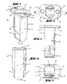
Ein Ausführungsbeispiel der Erfindung wirii im folgenden anhand der beiliegenden Zeichnungen beschrieben. Es zeigen:
- Fig. 1
- eine perspektivische Ansicht einer erfindungsgemässen Kiivette,
- Fig. 2
- eine erste Seitenansicht der Küvette gemäss Fig.1,
- Fig. 3
- eine Draufsicht der Küvette gemäss Fig.1,
- Fig. 4
- eine zweite Seitenansicht der Küvette gemäss Fig.1,
- Fig. 5
- eine Druntersicht der Küvette gemäss Fig.1,
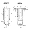
- Fig. 6
- einen Querschnitt durch die Linie A-A in Figuren 3 bzw. 7,
- Fig. 7
- einen Querschnitt durch die Linie B-B in Fig. 6,
- Fig. 1
- 2 shows a perspective view of a civette according to the invention,
- Fig. 2
- a first side view of the cuvette according to Figure 1,
- Fig. 3
- a plan view of the cuvette according to Figure 1,
- Fig. 4
- 2 shows a second side view of the cuvette according to FIG. 1,
- Fig. 5
- a bottom view of the cuvette according to Fig. 1,
- Fig. 6
- 3 shows a cross section through the line AA in FIGS. 3 and 7,
- Fig. 7
- 6 shows a cross section through the line BB in FIG. 6,
Die in den beiliegenden Figuren dargestellte Küvette (11) ist ein aus einem lichtdurchlässigen Kunststoff, z.B. aus einer Polymethylmethakrilat-Spritzgussmasse, in einem Stück geformten Teil. Durch ihre nachstehend beschriebene Ausbildung ist diese Küvette zur Durchführung optischer Messungen des Küvetteninhalts geeignet.The cuvette (11) shown in the accompanying figures is made of a translucent plastic, e.g. from a polymethyl methacrylate injection molding compound, molded in one piece. Due to the design described below, this cuvette is suitable for performing optical measurements of the cuvette contents.
Die Küvette 11 hat einen rohrförmigen Körper 12, der zwei planparallelen Wände 13, 14 und zwei Seitenwände 27, 28 besitzt, und der an einem Ende 15 offen und am entgegengesetzten Ende durch einen Boden 16 geschlossen ist. Bei der Durchführung optischer Messungen des Küvetteninhalts verläuft der verwendete Lichtstrahl durch die planparallelen Wände 13, 14 und senkrecht dazu.The
Jede der planparallelen Wände 13, 14 hat am offenen Ende 15 des Körpers eine Zunge 17, 18, die sich vom Rand des offenen Endes 15 nach aussen erstreckt, und die senkrecht zu den planparallelen Wänden 13, 14 gerichtet ist.Each of the plane-
Jede Zunge 17, 18 hat in ihrer Mitte eine zylindrische Vertiefung 21, 22. Die Zungen 17, 18 und ihre Vertiefungen 21, 22 sind in bezug auf die Längsachse (Y-Y) der Küvette 11 zueinander symmetrisch.Each
Das Durchmesser jeder der Vertiefungen 21, 22 beträgt vorzugsweise annähernd die Hälfte der Abmessung der Zunge 17 bzw. 18 in der zu den planparallelen Wänden 13, 14 senkrechten Richtung. Diese Abmessung ist die Breite der Zunge gemessen zwischen dem Rand des offenen Endes 15 des rohrförmigen Körpers 12 der Küvette und dem äussseren Rand der Zunge.The diameter of each of the
Die Tiefe jeder der Vertiefungen 21, 22 beträgt vorzugsweise annähernd die Hälfte der Abmessung der Zunge 17 bzw. 18 in der zu den planparallelen Wänden 13, 14 parallelen Richtung. Diese Abmessung ist die Dicke der Zunge.The depth of each of the
Bei jeder Zunge 17, 18 enthält der Bereich zwischen dem offenen Ende ihrer Vertiefung 21 bzw. 22 und dem äusseren Rand 23 bzw. 24 der Zunge vorzugsweise eine ebene Fläche 25, 26, die mit einer zur Längsachse Y-Y der Küvette senkrechten Ebene einen Winkel von annähernd 45° bildet.Each
Durch die oben beschriebene Ausbildung der Küvette 11 ist diese bestens dazu geeignet, von einem zangenförmigen, in den Zeichnungen nicht gezeigten Greifer einer Trasportvorrichtung gefasst zu werden, der mittels eines Antriebs und einer entsprechenden Steuerung dazu eingerichtet ist, die Küvette bei einer vorbestimmten Entnahme-Position zu fassen, sie zu einer vorbestimmten Abgabeposition zu tragen und sie dort abzugeben.Due to the design of the
Wenn die erfindungsgemässe Küvette zur Durchführung von spektralphotometrische Extinktionsmessungen eines darin enthaltenen Probe-Reagenz-Gemisches verwendet wird, verlauft der dazu verwendete Lichtstrahl durch den unteren Teil der planparallelen Wänden 13, 14, wobei dieser untere Teil an dem Boden 16 angrenzt. Der untere Bereich der planparallelen Wänden 13, 14, die als optische Messfenster benutzt werden, muss deshalb entsprechende optische Anforderungen erfüllen.If the cuvette according to the invention is used to carry out spectrophotometric extinction measurements of a sample-reagent mixture contained therein, the light beam used for this runs through the lower part of the plane-
Da die erfindungsgemässe Küvette zur Durchführung ausserdem zur Durchführung von Fluoreszenz-Polarisationsmessungen verwendbar sein soll, und da bei solchen Messungen Licht gemessen wird, das die Küvette durch den Boden 16 verlässt, muss auch der Boden der Küvette entsprechende optische Anforderungen erfüllen.Since the cuvette according to the invention should also be usable for carrying out fluorescence polarization measurements, and since such measurements measure light that leaves the cuvette through the
Um die erwünschte Genauigkeit bei der Durchführung von Fluoreszenz-Polarisationsmessungen erreichen zu können, die Aenderung der Polarizationsrichtung, die durch die beteiligte optische Fenster (d.h. der beteiligte Portionen der planparallelen Wänden 13, 14 und des Bodens 16) verursacht wird, muss sehr klein sein. Um diese Eigenschaft zu erreichen, wird bei der Herstellung der Küvette durch Spritzgiessen die Position des Angusses am obersten Rand der Küvette gewählt, d.h. möglichst weitvom unteren Teil der Küvette entfernt, wo sich die optische Messfenster befinden. Diese Wahl verursacht aber beim Herstellungsverfahren einen Materialzusammenfluss, der die Erzielung der gewünschten Eigenschaften der optischen Messfenster beinträchtigt und ausserdem Probleme bei der Entlüftung während des Spritzgiessens verursacht.In order to achieve the desired accuracy when carrying out fluorescence polarization measurements, the change in the direction of polarization, which is caused by the optical windows involved (ie the portions of the plane-
Diese Schwierigkeiten werden durch folgende Struktur der erfindungsgemässen Zelle. Wie aus den Figuren 1,2,4,5 und 7 ersichtlich, hat der rohrförmige Körper 12 zwei Seitenwände 27, 28, die sich zwischen den planparallelen Wänden 13, 14 erstrecken, welche Seitenwände einen oberen Teil und einen unteren Teil haben, wobei der untere Teil an den Boden 16 angrenzt, und wobei der untere Teil jeder Seitenwand 27, 28 einen äusseren Steg 31, 32 enthält, der sich in länglichen Richtung der Küvette zwischen dem oberen Teil der Seitenwand zu einem Punkt in der Nähe des Bodens 16 erstreckt. Das Vorhandensein dieser Stege als Teil der Küvette macht es möglich, der oben erwähnte, nachteilige Materialzusammenfluss während des Spritzgiessens zu vermeiden und dadurch die Erzielung der erforderlichen Eigenschaften der optischen Messfenster, die die Küvette sowohl zur Durchführung von spektralphotometrischen Messungen als auch Fluoreszenz-Polarisationsmessungen geeignet machen.These difficulties are caused by the following structure of the cell according to the invention. As can be seen from FIGS. 1, 2, 4, 5 and 7, the
Zur Erleichterung der Entlüftung beim Spritzgiessen der Küvette haben die Stege 31, 32 je einen länglichen, sehr feinen Spalt, der als Einsatztrennung dient. Dieser Spalt ist in den beiliegenden Figuren nicht dargestellt.To facilitate ventilation during the injection molding of the cuvette, the
Eine weiteres Merkmal der erfindungsgemässen Küvette ist, dass der Boden 16 die Form eines Halbzylinders hat. Diese Bodenform macht die Küvette zur Durchführung von Fluoreszenz-Polarisationsmessungen besonders geeignet, weil die dafür notwendigen Berechnungen durch den Umstand erheblich vereinfacht werden, dass der verwendete Lichtstrahl einen kreisförmigen Querschnitt hat und der Boden 16 zylindrisch ist.Another feature of the cuvette according to the invention is that the bottom 16 has the shape of a half cylinder. This base shape makes the cuvette particularly suitable for carrying out fluorescence polarization measurements because the calculations required for this are considerably simplified by the fact that the light beam used has a circular cross section and the
Claims (4)
- A cuvette (11) for performing optical measurements in an automatic analyser, which cuvettea) is a part moulded in one piece from a transparent plastic,b) has an elongate body (12) open at one end (15) and closed at the opposite end by a base (16),c) has at the open end (15) of the body two tongues (17,18) which extend outwardly from the edge of the open end (15) and perpendicularly to the longitudinal axis of the cuvette, each tongue having a recess (21, 22) and the tongues (17, 18) and their recesses (21, 22) being symmetrical relatively to one another with respect to the longitudinal axis (Y-Y) of the cuvette (11),characterized in thatd) it has a tubular body (12) which has two plane-parallel walls (13, 14) extending between the open erd (15) and the base (16),e) the plane-parallel walls (13, 14) are disposed perpendicularly to the tongues (17, 18),f) the base (16) has the shape of a semi-cylinder,g) the tubular body (12) has two side walls (27, 28) which extend between the plane-parallel walls (13, 14), which side walls have a top pa t and a bottom part, the bottom part adjoining the base (16) and the bottom central part of each side w ill (27, 28) containing an outer web (31, 32) which extends in the elongate direction of the cuvette between the top part of the side wall to a point near the base (16), andh) it is suitable both for performing spectralphotometric extinction measurements and also for performing fluorescence polarization measurements.
- A cuvette according to claim 1, characterized in that the diameter of each recess (21, 22) is approximately half the dimension of the tongue (17, 18) in the direction perpendicular to the plane-parallel walls (13, 14).
- A cuvette according to claim 1, characterized in that the depth of each recess (21, 22) is approximately half the dimension of the tongue (17, 18) in the direction parallel to the plane-parallel walls (13, 14).
- A cuvette according to claim 1, characterized in that the zone of each tongue (17, 18) situated between the open end of its recess (21, 22) and the outer edge (23, 24) of the tongue has a flat surface (25, 26) which forms an angle of approximately 45° with a plane perpendicular to the longitudinal axis (Y-Y) of the cuvette.
Applications Claiming Priority (2)
| Application Number | Priority Date | Filing Date | Title |
|---|---|---|---|
| CH136891 | 1991-05-07 | ||
| CH1368/91 | 1991-05-07 |
Publications (3)
| Publication Number | Publication Date |
|---|---|
| EP0512368A2 EP0512368A2 (en) | 1992-11-11 |
| EP0512368A3 EP0512368A3 (en) | 1993-02-03 |
| EP0512368B1 true EP0512368B1 (en) | 1996-06-26 |
Family
ID=4208783
Family Applications (1)
| Application Number | Title | Priority Date | Filing Date |
|---|---|---|---|
| EP92107229A Expired - Lifetime EP0512368B1 (en) | 1991-05-07 | 1992-04-28 | Cuvette for performing optical measurements |
Country Status (9)
| Country | Link |
|---|---|
| US (1) | US5437841A (en) |
| EP (1) | EP0512368B1 (en) |
| JP (2) | JPH05133881A (en) |
| AU (1) | AU660016B2 (en) |
| CA (1) | CA2067425C (en) |
| DE (1) | DE59206639D1 (en) |
| ES (1) | ES2089279T3 (en) |
| NZ (1) | NZ242564A (en) |
| SG (1) | SG43896A1 (en) |
Cited By (1)
| Publication number | Priority date | Publication date | Assignee | Title |
|---|---|---|---|---|
| US6562298B1 (en) | 1996-09-19 | 2003-05-13 | Abbott Laboratories | Structure for determination of item of interest in a sample |
Families Citing this family (28)
| Publication number | Priority date | Publication date | Assignee | Title |
|---|---|---|---|---|
| US5582184A (en) | 1993-10-13 | 1996-12-10 | Integ Incorporated | Interstitial fluid collection and constituent measurement |
| US5571479A (en) * | 1994-02-18 | 1996-11-05 | Hoffmann-La Roche Inc. | Cuvette |
| US5777303A (en) * | 1994-09-09 | 1998-07-07 | Gay Freres, Vente Et Exportation S.A. | Device for associating test tube samples with electronic labels for storage of identifying data |
| JP3251441B2 (en) * | 1994-09-30 | 2002-01-28 | シスメックス株式会社 | Cuvette and cuvette transporter |
| US5589137A (en) * | 1995-04-07 | 1996-12-31 | Lab-Interlink, Inc. | Specimen carrier |
| AU7015096A (en) * | 1995-09-08 | 1997-04-09 | Integ, Inc. | Body fluid sampler |
| US5879367A (en) | 1995-09-08 | 1999-03-09 | Integ, Inc. | Enhanced interstitial fluid collection |
| US6614522B1 (en) * | 1995-09-08 | 2003-09-02 | Integ, Inc. | Body fluid sampler |
| US5682233A (en) * | 1995-09-08 | 1997-10-28 | Integ, Inc. | Interstitial fluid sampler |
| US6624882B2 (en) | 1995-09-08 | 2003-09-23 | Integ, Inc. | Methods of sampling body fluid |
| US5795784A (en) | 1996-09-19 | 1998-08-18 | Abbott Laboratories | Method of performing a process for determining an item of interest in a sample |
| DE19826470C2 (en) * | 1998-06-13 | 2001-10-18 | Eppendorf Ag | Cuvette system and cuvette |
| US6368563B1 (en) | 1999-03-12 | 2002-04-09 | Integ, Inc. | Collection well for body fluid tester |
| GB0022013D0 (en) | 2000-09-07 | 2000-10-25 | Earth Canada Corp | Polyurethane oil de-emulsification unit |
| US6603544B1 (en) | 2002-02-06 | 2003-08-05 | Tech Ref, Inc. | Sample cell |
| US7138091B2 (en) * | 2003-07-18 | 2006-11-21 | Dade Behring Inc. | Reaction cuvette having anti-wicking features for use in an automatic clinical analyzer |
| US8211386B2 (en) | 2004-06-08 | 2012-07-03 | Biokit, S.A. | Tapered cuvette and method of collecting magnetic particles |
| US8343074B2 (en) * | 2004-06-30 | 2013-01-01 | Lifescan Scotland Limited | Fluid handling devices |
| US7554658B2 (en) * | 2005-02-08 | 2009-06-30 | Cdex, Inc. | Cuvette and cuvette cap |
| FR2957420A1 (en) * | 2010-03-11 | 2011-09-16 | Stago Diagnostica | HEAD FOR PREVENTING A REACTION CUP |
| JP6208596B2 (en) * | 2014-02-21 | 2017-10-04 | 株式会社日立ハイテクノロジーズ | Reaction cell and biochemical automatic analyzer |
| CN205246536U (en) | 2014-09-29 | 2016-05-18 | Bd科斯特公司 | A equipment for being directed at sample optical detection |
| US9494510B2 (en) * | 2015-02-06 | 2016-11-15 | John L. Sternick | Cuvette system |
| USD810959S1 (en) | 2015-09-29 | 2018-02-20 | Bd Kiestra B.V. | Cuvette tray |
| USD808036S1 (en) | 2015-09-29 | 2018-01-16 | Bd Kiestra B.V. | Cuvette |
| CN105891114B (en) * | 2016-05-25 | 2019-03-29 | 广西科技大学 | For measuring the cuvette and its optical system of scattering spectrum |
| USD855826S1 (en) | 2017-07-10 | 2019-08-06 | Gen-Probe Incorporated | Receptacle holder |
| US20210181088A1 (en) * | 2018-04-28 | 2021-06-17 | Guangdong Poctman Life Technology Co., Ltd. | Reaction vessel for testing |
Family Cites Families (22)
| Publication number | Priority date | Publication date | Assignee | Title |
|---|---|---|---|---|
| DE1773584A1 (en) * | 1967-06-13 | 1973-01-04 | Xerox Corp | REACTION VESSEL |
| CH493834A (en) * | 1968-05-02 | 1970-07-15 | Eppendorf Geraetebau Netheler | Plastic reaction vessel for the photometric investigation of small amounts of liquid |
| FR2036769A1 (en) * | 1969-03-26 | 1970-12-31 | Dassault Electronique | |
| SE385988B (en) * | 1973-06-21 | 1976-07-26 | Platmanufaktur Ab | IDENTIFICATION DEVICE FOR FORM NUMBER READING ON MACHINE-FORMED PRODUCTS EXV. PLASTIC OR GLASS PRODUCTS |
| US4024857A (en) * | 1974-12-23 | 1977-05-24 | Becton, Dickinson And Company | Micro blood collection device |
| US3994594A (en) * | 1975-08-27 | 1976-11-30 | Technicon Instruments Corporation | Cuvette and method of use |
| US4043678A (en) * | 1976-03-01 | 1977-08-23 | Technicon Instruments Corporation | Cuvette |
| US4119407A (en) * | 1976-03-08 | 1978-10-10 | Bio-Dynamics, Inc. | Cuvette with reagent release means |
| JPS5536807A (en) * | 1978-09-07 | 1980-03-14 | Tdk Electronics Co Ltd | Power supplyyfree type rechargeable display |
| JPS55136958A (en) * | 1979-04-14 | 1980-10-25 | Olympus Optical Co Ltd | Automatic analyzer |
| DE2922697A1 (en) * | 1979-06-02 | 1980-12-11 | Hoechst Ag | CUEVETTE FOR OPTICAL EXAMINATION OF LIQUIDS |
| US4263256A (en) * | 1979-11-05 | 1981-04-21 | Coulter Electronics, Inc. | Cuvettes for automatic chemical apparatus |
| AT382971B (en) * | 1981-06-16 | 1987-05-11 | Hoffmann La Roche | METHOD AND DEVICE FOR MEASURING THE BLOOD CLUTTING TIME |
| US4371498A (en) * | 1981-06-19 | 1983-02-01 | Medical Laboratory Automation, Inc. | Coded cuvette for use in testing apparatus |
| NL8105341A (en) * | 1981-11-26 | 1983-06-16 | Akzo Nv | DIAGNOSTIC TEST METHOD. |
| US4799599A (en) * | 1982-07-30 | 1989-01-24 | Ciba Corning Diagnostics Corp. | Specimen cup and cap assembly for clinical analyzer |
| JPS58131540A (en) * | 1982-10-05 | 1983-08-05 | Olympus Optical Co Ltd | Cuvette for chemical analysis |
| FI81913C (en) * | 1984-02-23 | 1990-12-10 | Hoffmann La Roche | SKAOLANORDNING. |
| JPS6342350U (en) * | 1986-09-06 | 1988-03-19 | ||
| JPH051280Y2 (en) * | 1987-10-12 | 1993-01-13 | ||
| US5098661A (en) * | 1988-11-16 | 1992-03-24 | Medical Laboratory Automation, Inc. | Coded cuvette for use in testing apparatus |
| JPH0394141A (en) * | 1989-09-06 | 1991-04-18 | Hitachi Ltd | Structural body of reaction cell |
-
1992
- 1992-04-28 DE DE59206639T patent/DE59206639D1/en not_active Expired - Lifetime
- 1992-04-28 EP EP92107229A patent/EP0512368B1/en not_active Expired - Lifetime
- 1992-04-28 ES ES92107229T patent/ES2089279T3/en not_active Expired - Lifetime
- 1992-04-28 CA CA002067425A patent/CA2067425C/en not_active Expired - Fee Related
- 1992-04-28 SG SG1996004368A patent/SG43896A1/en unknown
- 1992-04-30 NZ NZ242564A patent/NZ242564A/en not_active IP Right Cessation
- 1992-05-04 AU AU16006/92A patent/AU660016B2/en not_active Ceased
- 1992-05-07 JP JP4114942A patent/JPH05133881A/en active Pending
-
1994
- 1994-01-21 US US08/184,521 patent/US5437841A/en not_active Expired - Lifetime
-
1996
- 1996-01-12 JP JP1996000046U patent/JP2539722Y2/en not_active Expired - Lifetime
Cited By (1)
| Publication number | Priority date | Publication date | Assignee | Title |
|---|---|---|---|---|
| US6562298B1 (en) | 1996-09-19 | 2003-05-13 | Abbott Laboratories | Structure for determination of item of interest in a sample |
Also Published As
| Publication number | Publication date |
|---|---|
| JP2539722Y2 (en) | 1997-06-25 |
| AU1600692A (en) | 1992-11-12 |
| CA2067425C (en) | 1996-09-24 |
| SG43896A1 (en) | 1997-11-14 |
| EP0512368A2 (en) | 1992-11-11 |
| JPH05133881A (en) | 1993-05-28 |
| JPH081384U (en) | 1996-09-13 |
| EP0512368A3 (en) | 1993-02-03 |
| ES2089279T3 (en) | 1996-10-01 |
| AU660016B2 (en) | 1995-06-08 |
| US5437841A (en) | 1995-08-01 |
| NZ242564A (en) | 1994-02-25 |
| DE59206639D1 (en) | 1996-08-01 |
| CA2067425A1 (en) | 1992-11-08 |
Similar Documents
| Publication | Publication Date | Title |
|---|---|---|
| EP0512368B1 (en) | Cuvette for performing optical measurements | |
| EP0668496B1 (en) | Cuvette for performing optical measurements | |
| DE3005508C2 (en) | ||
| DE2641097C2 (en) | Cell for performing optical analyzes and their use for hemoglobin determination | |
| DE60213873T2 (en) | STACKABLE SAMPLE TRAY ASSEMBLY | |
| DE3537734C2 (en) | Device for an immunochemical agglutination reaction of liquid particle reagents | |
| EP0618443B1 (en) | Test-strip analysis system | |
| DE69828743T2 (en) | DEVICE FOR AUTOMATICALLY READING AN IDENTIFICATION CODE ON TUBULAR CONTAINERS | |
| DE19826470A1 (en) | Cuvette for measuring radiation absorption in liquid samples | |
| DE2302448B2 (en) | Sample cell with agitator, especially for spectrophotometric devices | |
| EP3025779A1 (en) | Incubation tray | |
| EP3025780A1 (en) | Incubation tray | |
| AT500523A1 (en) | DEVICE FOR PROTEIN CRYSTALLIZATION | |
| DE2922697A1 (en) | CUEVETTE FOR OPTICAL EXAMINATION OF LIQUIDS | |
| DD239473A1 (en) | SAMPLE SUPPLIER FOR DISCRETE ANALYSIS OF LIQUID ANALYSIS ASSAYS | |
| WO1995009352A1 (en) | Cartridge for treating samples for histological examination, in particular for preparing slices | |
| EP1008844B1 (en) | Multi-cuvette rotor | |
| DE4016617A1 (en) | Holder plate e.g. for blood samples - used with structured second plate to form gaps of variable vol. allowing use of small samples | |
| DE19512430A1 (en) | Microtiter plate | |
| DE2905234A1 (en) | SAMPLE CELL AND RUEHRER FOR SPECTROPHOTOMETRY | |
| DE4300231C1 (en) | Petri dish - has side mounting with upper projecting pin and lower recess to form stack with swing access to each dish | |
| EP0896662B1 (en) | Cuvette rail | |
| EP0530186B1 (en) | Drop plate for wet or damp preparations, e.g. blood | |
| DE3108474A1 (en) | COUPLING CHANGER FOR A FLUORESCENCE MEASURING DEVICE | |
| DE2343149A1 (en) | HAEMATOKRIT TUBE HOLDING AND MEASURING DEVICE |
Legal Events
| Date | Code | Title | Description |
|---|---|---|---|
| PUAI | Public reference made under article 153(3) epc to a published international application that has entered the european phase |
Free format text: ORIGINAL CODE: 0009012 |
|
| 17P | Request for examination filed |
Effective date: 19920429 |
|
| AK | Designated contracting states |
Kind code of ref document: A2 Designated state(s): BE CH DE ES FR GB IT LI NL |
|
| PUAL | Search report despatched |
Free format text: ORIGINAL CODE: 0009013 |
|
| AK | Designated contracting states |
Kind code of ref document: A3 Designated state(s): BE CH DE ES FR GB IT LI NL |
|
| 17Q | First examination report despatched |
Effective date: 19930728 |
|
| GRAH | Despatch of communication of intention to grant a patent |
Free format text: ORIGINAL CODE: EPIDOS IGRA |
|
| GRAA | (expected) grant |
Free format text: ORIGINAL CODE: 0009210 |
|
| ITF | It: translation for a ep patent filed |
Owner name: BARZANO' E ZANARDO MILANO S.P.A. |
|
| AK | Designated contracting states |
Kind code of ref document: B1 Designated state(s): BE CH DE ES FR GB IT LI NL |
|
| REF | Corresponds to: |
Ref document number: 59206639 Country of ref document: DE Date of ref document: 19960801 |
|
| ET | Fr: translation filed | ||
| REG | Reference to a national code |
Ref country code: ES Ref legal event code: FG2A Ref document number: 2089279 Country of ref document: ES Kind code of ref document: T3 |
|
| GBT | Gb: translation of ep patent filed (gb section 77(6)(a)/1977) |
Effective date: 19960926 |
|
| REG | Reference to a national code |
Ref country code: ES Ref legal event code: FG2A Ref document number: 2089279 Country of ref document: ES Kind code of ref document: T3 |
|
| PLBE | No opposition filed within time limit |
Free format text: ORIGINAL CODE: 0009261 |
|
| STAA | Information on the status of an ep patent application or granted ep patent |
Free format text: STATUS: NO OPPOSITION FILED WITHIN TIME LIMIT |
|
| 26N | No opposition filed | ||
| REG | Reference to a national code |
Ref country code: GB Ref legal event code: IF02 |
|
| PGFP | Annual fee paid to national office [announced via postgrant information from national office to epo] |
Ref country code: BE Payment date: 20080507 Year of fee payment: 17 |
|
| PGFP | Annual fee paid to national office [announced via postgrant information from national office to epo] |
Ref country code: NL Payment date: 20080325 Year of fee payment: 17 |
|
| PGFP | Annual fee paid to national office [announced via postgrant information from national office to epo] |
Ref country code: GB Payment date: 20090312 Year of fee payment: 18 |
|
| PGFP | Annual fee paid to national office [announced via postgrant information from national office to epo] |
Ref country code: CH Payment date: 20090430 Year of fee payment: 18 |
|
| BERE | Be: lapsed |
Owner name: F. *HOFFMANN-LA ROCHE A.G. Effective date: 20090430 |
|
| NLV4 | Nl: lapsed or anulled due to non-payment of the annual fee |
Effective date: 20091101 |
|
| PG25 | Lapsed in a contracting state [announced via postgrant information from national office to epo] |
Ref country code: NL Free format text: LAPSE BECAUSE OF NON-PAYMENT OF DUE FEES Effective date: 20091101 |
|
| PG25 | Lapsed in a contracting state [announced via postgrant information from national office to epo] |
Ref country code: BE Free format text: LAPSE BECAUSE OF NON-PAYMENT OF DUE FEES Effective date: 20090430 |
|
| REG | Reference to a national code |
Ref country code: CH Ref legal event code: PL |
|
| GBPC | Gb: european patent ceased through non-payment of renewal fee |
Effective date: 20100428 |
|
| PG25 | Lapsed in a contracting state [announced via postgrant information from national office to epo] |
Ref country code: LI Free format text: LAPSE BECAUSE OF NON-PAYMENT OF DUE FEES Effective date: 20100430 Ref country code: CH Free format text: LAPSE BECAUSE OF NON-PAYMENT OF DUE FEES Effective date: 20100430 |
|
| PG25 | Lapsed in a contracting state [announced via postgrant information from national office to epo] |
Ref country code: GB Free format text: LAPSE BECAUSE OF NON-PAYMENT OF DUE FEES Effective date: 20100428 |
|
| PGFP | Annual fee paid to national office [announced via postgrant information from national office to epo] |
Ref country code: FR Payment date: 20110331 Year of fee payment: 20 |
|
| PGFP | Annual fee paid to national office [announced via postgrant information from national office to epo] |
Ref country code: ES Payment date: 20110414 Year of fee payment: 20 Ref country code: DE Payment date: 20110429 Year of fee payment: 20 |
|
| PGFP | Annual fee paid to national office [announced via postgrant information from national office to epo] |
Ref country code: IT Payment date: 20110423 Year of fee payment: 20 |
|
| REG | Reference to a national code |
Ref country code: DE Ref legal event code: R071 Ref document number: 59206639 Country of ref document: DE |
|
| REG | Reference to a national code |
Ref country code: DE Ref legal event code: R071 Ref document number: 59206639 Country of ref document: DE |
|
| REG | Reference to a national code |
Ref country code: ES Ref legal event code: FD2A Effective date: 20120717 |
|
| PG25 | Lapsed in a contracting state [announced via postgrant information from national office to epo] |
Ref country code: DE Free format text: LAPSE BECAUSE OF EXPIRATION OF PROTECTION Effective date: 20120429 Ref country code: ES Free format text: LAPSE BECAUSE OF EXPIRATION OF PROTECTION Effective date: 20120429 |