EP0572185B1 - Sampling device - Google Patents
Sampling device Download PDFInfo
- Publication number
- EP0572185B1 EP0572185B1 EP93303964A EP93303964A EP0572185B1 EP 0572185 B1 EP0572185 B1 EP 0572185B1 EP 93303964 A EP93303964 A EP 93303964A EP 93303964 A EP93303964 A EP 93303964A EP 0572185 B1 EP0572185 B1 EP 0572185B1
- Authority
- EP
- European Patent Office
- Prior art keywords
- container
- sample
- probe
- sampling
- capillary
- Prior art date
- Legal status (The legal status is an assumption and is not a legal conclusion. Google has not performed a legal analysis and makes no representation as to the accuracy of the status listed.)
- Expired - Lifetime
Links
Images


Classifications
-
- G—PHYSICS
- G01—MEASURING; TESTING
- G01N—INVESTIGATING OR ANALYSING MATERIALS BY DETERMINING THEIR CHEMICAL OR PHYSICAL PROPERTIES
- G01N35/00—Automatic analysis not limited to methods or materials provided for in any single one of groups G01N1/00 - G01N33/00; Handling materials therefor
- G01N35/10—Devices for transferring samples or any liquids to, in, or from, the analysis apparatus, e.g. suction devices, injection devices
-
- G—PHYSICS
- G01—MEASURING; TESTING
- G01N—INVESTIGATING OR ANALYSING MATERIALS BY DETERMINING THEIR CHEMICAL OR PHYSICAL PROPERTIES
- G01N30/00—Investigating or analysing materials by separation into components using adsorption, absorption or similar phenomena or using ion-exchange, e.g. chromatography or field flow fractionation
- G01N30/02—Column chromatography
- G01N30/04—Preparation or injection of sample to be analysed
- G01N30/16—Injection
- G01N30/18—Injection using a septum or microsyringe
- G01N2030/185—Injection using a septum or microsyringe specially adapted to seal the inlet
-
- G—PHYSICS
- G01—MEASURING; TESTING
- G01N—INVESTIGATING OR ANALYSING MATERIALS BY DETERMINING THEIR CHEMICAL OR PHYSICAL PROPERTIES
- G01N35/00—Automatic analysis not limited to methods or materials provided for in any single one of groups G01N1/00 - G01N33/00; Handling materials therefor
- G01N2035/00178—Special arrangements of analysers
- G01N2035/00237—Handling microquantities of analyte, e.g. microvalves, capillary networks
-
- G—PHYSICS
- G01—MEASURING; TESTING
- G01N—INVESTIGATING OR ANALYSING MATERIALS BY DETERMINING THEIR CHEMICAL OR PHYSICAL PROPERTIES
- G01N35/00—Automatic analysis not limited to methods or materials provided for in any single one of groups G01N1/00 - G01N33/00; Handling materials therefor
- G01N2035/00178—Special arrangements of analysers
- G01N2035/00277—Special precautions to avoid contamination (e.g. enclosures, glove- boxes, sealed sample carriers, disposal of contaminated material)
-
- G—PHYSICS
- G01—MEASURING; TESTING
- G01N—INVESTIGATING OR ANALYSING MATERIALS BY DETERMINING THEIR CHEMICAL OR PHYSICAL PROPERTIES
- G01N30/00—Investigating or analysing materials by separation into components using adsorption, absorption or similar phenomena or using ion-exchange, e.g. chromatography or field flow fractionation
- G01N30/02—Column chromatography
- G01N30/04—Preparation or injection of sample to be analysed
- G01N30/24—Automatic injection systems
-
- G—PHYSICS
- G01—MEASURING; TESTING
- G01N—INVESTIGATING OR ANALYSING MATERIALS BY DETERMINING THEIR CHEMICAL OR PHYSICAL PROPERTIES
- G01N35/00—Automatic analysis not limited to methods or materials provided for in any single one of groups G01N1/00 - G01N33/00; Handling materials therefor
- G01N35/10—Devices for transferring samples or any liquids to, in, or from, the analysis apparatus, e.g. suction devices, injection devices
- G01N35/1004—Cleaning sample transfer devices
-
- Y—GENERAL TAGGING OF NEW TECHNOLOGICAL DEVELOPMENTS; GENERAL TAGGING OF CROSS-SECTIONAL TECHNOLOGIES SPANNING OVER SEVERAL SECTIONS OF THE IPC; TECHNICAL SUBJECTS COVERED BY FORMER USPC CROSS-REFERENCE ART COLLECTIONS [XRACs] AND DIGESTS
- Y10—TECHNICAL SUBJECTS COVERED BY FORMER USPC
- Y10T—TECHNICAL SUBJECTS COVERED BY FORMER US CLASSIFICATION
- Y10T436/00—Chemistry: analytical and immunological testing
- Y10T436/11—Automated chemical analysis
- Y10T436/113332—Automated chemical analysis with conveyance of sample along a test line in a container or rack
- Y10T436/114165—Automated chemical analysis with conveyance of sample along a test line in a container or rack with step of insertion or removal from test line
-
- Y—GENERAL TAGGING OF NEW TECHNOLOGICAL DEVELOPMENTS; GENERAL TAGGING OF CROSS-SECTIONAL TECHNOLOGIES SPANNING OVER SEVERAL SECTIONS OF THE IPC; TECHNICAL SUBJECTS COVERED BY FORMER USPC CROSS-REFERENCE ART COLLECTIONS [XRACs] AND DIGESTS
- Y10—TECHNICAL SUBJECTS COVERED BY FORMER USPC
- Y10T—TECHNICAL SUBJECTS COVERED BY FORMER US CLASSIFICATION
- Y10T436/00—Chemistry: analytical and immunological testing
- Y10T436/11—Automated chemical analysis
- Y10T436/113332—Automated chemical analysis with conveyance of sample along a test line in a container or rack
- Y10T436/114998—Automated chemical analysis with conveyance of sample along a test line in a container or rack with treatment or replacement of aspirator element [e.g., cleaning, etc.]
-
- Y—GENERAL TAGGING OF NEW TECHNOLOGICAL DEVELOPMENTS; GENERAL TAGGING OF CROSS-SECTIONAL TECHNOLOGIES SPANNING OVER SEVERAL SECTIONS OF THE IPC; TECHNICAL SUBJECTS COVERED BY FORMER USPC CROSS-REFERENCE ART COLLECTIONS [XRACs] AND DIGESTS
- Y10—TECHNICAL SUBJECTS COVERED BY FORMER USPC
- Y10T—TECHNICAL SUBJECTS COVERED BY FORMER US CLASSIFICATION
- Y10T436/00—Chemistry: analytical and immunological testing
- Y10T436/11—Automated chemical analysis
- Y10T436/119163—Automated chemical analysis with aspirator of claimed structure
-
- Y—GENERAL TAGGING OF NEW TECHNOLOGICAL DEVELOPMENTS; GENERAL TAGGING OF CROSS-SECTIONAL TECHNOLOGIES SPANNING OVER SEVERAL SECTIONS OF THE IPC; TECHNICAL SUBJECTS COVERED BY FORMER USPC CROSS-REFERENCE ART COLLECTIONS [XRACs] AND DIGESTS
- Y10—TECHNICAL SUBJECTS COVERED BY FORMER USPC
- Y10T—TECHNICAL SUBJECTS COVERED BY FORMER US CLASSIFICATION
- Y10T436/00—Chemistry: analytical and immunological testing
- Y10T436/25—Chemistry: analytical and immunological testing including sample preparation
- Y10T436/2575—Volumetric liquid transfer
Definitions
- This invention relates to a device which is used for sampling fluids which are to be analyzed by a laboratory instrument. Although many applications are contemplated, the one used to describe the operation of the device is for analysis of sampled blood.
- the blood is normally collected by using a syringe to draw the blood or by collecting the blood in a glass capillary tube.
- the currently available analytical instruments use three methods of delivering the blood sample to the instrument. First, if a syringe is used, the sample might be injected into the instrument sampling port. There is much variability in this approach, due to the fact that (1) the force used to inject the sample may vary from operator to operator, (2) the force used to inject the sample into the instrument may vary from test to test, (3) the force may vary throughout the injection of a single sample, and (4) the sample size may vary from test to test.
- a novel fluid sampling device has been developed. This device provides for sample entry to be handled automatically by the instrument, thus-allowing the operator to be involved in other activities (such as monitoring other instruments, etc.) while the sampling process is underway. It also assures reproduceable sample size, automatically cleans the sampling device between samples, and reduces the risk of user injury from innoculation by the probe. Furthermore, the sampling system allows for the use of any forseeable collection mechanism.
- Figure 1 represents the sampling device during the process of drawing a sample from a syringe.
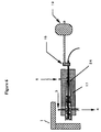
- Figure 2 represents the sampling device drawing a sample from a capillary.
- Figure 3 represents the front view of the "smart door” system.
- Figure 4 represents the side view of the "smart door” system.
- Figure 5 represents the probe obstruction detection system.
- Figure 6 represents the wash system.
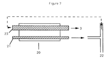
- Figure 7 represents the foam generation system.
- the present invention provides a device for sampling a material from a container, characterised in that the device comprises:
- the present invention provides a device for detecting the presence and diameter of a container, characterised in that the device comprises:
- the present invention provides a device for sampling a material from a syringe or capillary which detects the presence of, and avoids, obstructions in its path, characterised in that the device comprises:
- a novel sampling device intended primarily for use in handling blood samples to be analyzed in medical diagnostics instruments, has been developed.
- This sampling device also has utility in other applications where liquid, gaseous, solid or mixed-phase (e.g., suspensions, such as blood or plasma) samples are drawn. Examples of other instruments where the device could show utility include analytical chemistry instruments, air sampling and analysis instruments, food sampling instruments, etc.).
- the mechanism involved in sensing the type of container holding the sample, drawing the sample from the container, cleaning the portions of the mechanism exposed to sample, and related activities is referred to collectively as the device. Portions of the device are referred to as systems. The entire mechanism, including the “device” and the portion which analyzes the sample drawn, is referred to as the instrument.
- the main structure of the sampling device are that:
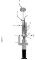
- FIG. 1 shows a schematic of the sampling device with a syringe as the sample holder.
- 1 represents the "smart door”
- 2 represents the sample entry Luer
- 3 is the inlet for the wash solution
- 4 is the outlet for pumped waste
- 5 is the probe
- 6 is the gas and reagent port (where standardizing gas and liquid samples are drawn into the instrument and overflow sample is allowed to escape.)
- 17 represents the capillary seal through which the probe is moved and which forms a seal with the probe. It also creates a seal with the inserted capillary.
- 18 represents the probe obstruction detection system, to be discussed further in reference to Figure 5
- 19 represents the linear bidirectional actuator, which moves the probe into a syringe.
- the sample entry Luer is tapered using the American National Standards Institute ANSI/HIMA MD70.1-1983 standard taper that is used on all syringes, and contains the gas and reagent port referred to above (item 6 ).
- the syringe, without its needle, is held tightly by friction against the female Luer taper, and the sampling device automatically draws the sample, thus freeing the technician to perform other tasks while the sampling takes place.
- the Luer can be made of any material that will hold the syringe in the desired orientation and will not contaminate the sample, for example polyethylene, stainless steel, silicone, urethane, "Teflon”®, and preferably clear acrylic, for example "Polycast”®, made by Rohm and Haas, or "Perspex”®, made by ICI.
- the acrylic PMMA polymethylmethacrylate
- All standard types of syringes will fit into the Luer, although it is most likely that syringes holding between 1cc and 30cc will be used.
- capillaries that are used to collect blood samples will also fit into the sample entry system and the preferred embodiment is one in which the capillary will be firmly held in a horizontal position in the capillary seal.
- the capillary seal is designed to have a conical shape in order to hold all the different capillary sizes.
- the capillary seal can be made of any material that is flexible enough to hold and seal the capillary and the sample probe. The material must also not contaminate the sample. For example, thermoset rubbers, such as silicon (for example, General Electric "GE 4404", 43-50 Shore A durometer hardness), and thermoplastic rubbers, such as "Krayton”® G or D (from Shell), can be used. Because of the capillary seal design, all foreseeable diameters of capillaries can be used, although the most common are expected to be between 50 and 175 ⁇ l volume.
- the materials discussed above hold the syringe, capillary or other sample container in the Luer or capillary seal primarily by frictional forces between the sample container and the Luer.
- a material or design that does not cause the sample container to be held by friction can be used, but in that case a different mechanism for holding the sample container in the Luer must be included.
- the sample container (syringe, capillary, or other container) is held rigidly in the center of the Luer and aligned concentrically with the narrow-opening end of the Luer.
- the operator presses the start switch, and the "smart door” closes by rotating about the pivot point connecting it to the device.
- This "smart door” is actually a moving arm which determines the type of container present by measuring the diameter thereof. The location where it stops its motion is an indicator to the device of the type of blood holding container that is being used.
- the type of sample container detected indicates to the instrument how a sample is to be drawn from the sampling device. If a syringe is detected, a movable probe is inserted into the syringe to draw, in a reproduceable manner, using vacuum applied to the probe, the sample of blood from the container of blood. If a capillary is detected, a vacuum, applied to the probe in a reproduceable manner, draws the sample from the capillary. Because of the low vacuum used in the sampling pump, there is little chance that a clot will get into and clog the instrument.
- the instrument draws the sample from the syringe or other sample holder, the user is instructed to remove the sample holder, at which time the door automatically closes, blocking the Luer entry. While entry of a sample is prevented, the instrument performs the operations of analyzing the previously drawn sample, washing the Luer and sampling probe, and calibrating the instrument.
- Analytical instruments currently in the marketplace provide for sample entry "straight ahead" into the instrument (i.e., the syringe or capillary points along a line going from the operator).
- the novel device if there is a sidewise orientation of the sampling system, particularly if it is pointing towards the right side, when the user is facing the instrument.
- the syringe (or other sample holder) no longer extends towards the operator, but rather along the instrument or over a "guard" that can easily be designed into the instrument, the syringe and sample are less likely to be accidentally jarred by the operator and knocked from the instrument.
- the probe does not operate until the smart door first detects a sample collection device (i.e., syringe, capillary, etc.) inserted in the Luer; due to the ability of the probe to detect obstructions, the likelihood of its puncturing skin is negligible; the entire sampling takes place in a closed area, reducing spillage, backsplash and exposure to blood; and automatic washing of the system between samples reduces exposure due to contamination from sample residues.
- a sample collection device i.e., syringe, capillary, etc.
- the Smart Door Assembly is shown in Figures 3 (front view) and 4 (side view).
- the door, 1 is coupled to a shaft, 7 , that pivots about a contact point and rotates via a stepper motor, 8 .
- the door shaft has a drive piece, 9 , and a driven piece, 10 .
- the drive piece is directly coupled to the stepper motor.
- the driven piece is connected (via a spring coupling) to the drive piece, and it includes the door and the optical detector, 11 , for determining the stopping point for the flag, 12 , on the driven piece, which has the same movement as the door.
- the home or fully opened, location and the fully closed location, and these positions are established by optical position detectors.
- Other locations for common types of syringes and capillaries are also programmed in the instrument.
- the stepper motor counts the number of steps that the shaft has taken from its home position until it intercepts the sampling device. The point of interception is determined when the optical detector, 11 , is tripped.
- Unusual sampling devices for example special sizes of syringes and capillaries, can be programmed into the instrument by the user.
- the following data might represent the table of steps for several sampling devices: Position/Container Number of Steps Door open 0 30 cc syringe 25-30 12 cc syringe 39-40 3 cc syringe 79-80 2 cc syringe 89-90 1 cc syringe 98-99 275 ⁇ l capillary 114-115 100 ⁇ l capillary 133-134 Door closed 175
- a probe that has a sufficiently small outside diameter (typically from 0.81 - 1.17 mm (from 0.032 - 0.046 in.)) so that it can fit into the various syringes being used, is employed to draw sample in a reproduceable fashion from the syringes.
- the sample probe can be made of metal (e.g., stainless steel, titanium, inconel or plastic (e.g., "Peek”® (ICI America), "Kel-F”® (3M), etc.).
- the probe can remain stationary, and the syringe and Luer can move laterally until the probe is inside the syringe.
- a vacuum system is connected to the capillary for withdrawing an aliquot of sample.
- the motorized probe has the ability to sense a small obstruction at the probe tip, for example a syringe plunger, a finger, etc. As small a force as 113g (0.25 bounds) can be detected, which is less than what would be encountered in hitting intact skin. As a result, the device minimizes the chance of injuring a technician. In addition, the device adapts the sampling procedure to the volume of sample in the container, assuring that air will not be drawn into the instrument along with the sample. If the probe encounters an obstruction during its outward motion, it senses the obstruction, stops its forward motion, retracts, and the instrument displays a probe obstruction message to the user.
- a small obstruction at the probe tip for example a syringe plunger, a finger, etc.
- 113g 113g (0.25 bounds
- the probe will be withdrawn, and an error message will be displayed. If the system determines that too small of a sample is present, the probe will be withdrawn, and an error message will be displayed. If the instrument should fail to detect a problem and proceeds with sampling, two detectors in the sampling line assure that there is present an integral sample (i.e., the detectors determine if a bubble exists in the sample line, using, for example, a conductivity or optical measuring device). If a problem with the sample is detected, an error message is displayed.
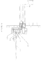
- the Probe Obstruction Detection System is shown in Figure 5.
- the method of detecting the obstruction utilizes an optical detector, 13 , a flag, 14 , mounted on a cantilever flex beam, 15 , and a push rod, 16 that is in contact with the flex beam.
- the probe pushes on the push rod, the flex beam bends and the flat interrupts the optical detector's light path.
- the obstruction detection sensitivity can be increased or decreased.
- the device senses when a sample or reference has been drawn and initiates the washing cycle after each material (sample or reference) has been drawn. During this washing cycle the probe, capillary conical seal, and related components are automatically cleaned to avoid contamination. It should be noted that, during each cleaning operation, the smart door is automatically closed in order to prevent the introduction of a new sample.
- the wash and waste fluidic paths reside within the Luer. (See Figure 6.)
- the wash solution which contains a surfactant, such as "Brij”® (from ICI) or “Triton”® X100 (from Rohm and Haas), is introduced in the Luer directly above the probe's outside surface, 3 , while the probe is located in the Luer/probe wash position (see Fig. 6).
- the wash solution fills the Luer and capillary seal, and it surrounds the outside of the probe.
- the outside area of the probe that is surrounded with the foam wash solution is the area that was inserted into the syringe and thus requires washing.)
- the waste is collected in the Luer at the probe's outside bottom surface, 4 .
- the outside of the probe exposed to the blood sample is washed inside the Luer without the probe coming in contact with any parts of the instrument.
- the probe is withdrawn into the capillary seal, 17 , where the washing of the capillary seal and interior of the probe takes place.
- the washing cycle takes place at the same time that the instrument's measurement cycle occurs, in order to optimize instrument throughput.
- cleaning also occurs by the wiping of the outside of the probe by the narrowest portion of the capillary seal ( 26 ) when the probe is withdrawn into its home position, which is the reagent / gas / wash entry location ( 6 ).
- the narrowest portion of the capillary also provides a seal with the probe.
- wash solution does not leak because of the properties of the foam wash solution (surface tension, etc.).
- the timing of the peristaltic pump, which delivers the wash solution, and the waste pump are synchronized so that there will be no excess wash solution to drip out of the Luer.
- the Smart Door could make contact with the Luer port, especially if a wash solution having other properties (e.g., a solution containing an organic solvent) were used.
- the generation and delivery of foam wash into the Luer is the technique used to wash and clean the blood from the outside of the probe and the inside of the Luer.
- the generation of foam in a controlled manner has been found to provide cleaning in a reliable, simple and effective manner. It has been found to be more efficient, due to the fluid volume consumption and drip minimization, than systems currently used by other instruments, which involve either immersing the probe into a wash bath or manual washing of the sampling probe.
- the techniques used in other instruments require either expensive hardware or manual intervention.
- the foam wash (see Figure 7) is developed by having two different inside diameter size tubes (pump tubes) on a peristaltic pump, 20 .
- the difference in the inside diameter of the tubing is required to obtain an optimum flow rate ratio of surfactant to water.
- the smaller diameter tube, 21 pushes wash solution into a "T" junction, 22 , where the larger tube, 23 , pulls air in front of the "T" junction.
- the liquid and air form a mixture in this "T" junction.
- the size of the air to liquid microsegments can be varied by changing the tubing diameters.
- the larger diameter tube also delivers the air/liquid mixture via the wash solution inlet ( 3 ) into the Luer, where they become foam (i.e., form a foam structure).
- the liquid segments should be smaller than 5 ⁇ l in volume and preferably about 1 ⁇ l in volume.
- the foam wash and waste are delivered to the waste resevoir ( 24 in Figure 1) from the Luer by vacuum generated by a waste pump. Variations in the foam generation system are contemplated as a means of expanding the usefulness of the device. For example, it would be possible to increase the number of tubes and, therefore, utilize this system to mix components and create a foam from a multicomponent solution.
- the device can be used to draw suspensions such as liquid food samples, gas samples analyzed for occupational health monitoring, etc. These samples can then be delivered to the appropriate analytical system.
Abstract
Description
- This invention relates to a device which is used for sampling fluids which are to be analyzed by a laboratory instrument. Although many applications are contemplated, the one used to describe the operation of the device is for analysis of sampled blood. The blood is normally collected by using a syringe to draw the blood or by collecting the blood in a glass capillary tube.
- The currently available analytical instruments use three methods of delivering the blood sample to the instrument. First, if a syringe is used, the sample might be injected into the instrument sampling port. There is much variability in this approach, due to the fact that (1) the force used to inject the sample may vary from operator to operator, (2) the force used to inject the sample into the instrument may vary from test to test, (3) the force may vary throughout the injection of a single sample, and (4) the sample size may vary from test to test.
- Second, some instruments aspirate the sample from the syringe. For these instruments to be operable, a sampling probe protruding from the instrument must be manually aligned with the syringe carrying the blood. This approach takes much time, demands manual dexterity on the part of the user, requires cleaning the probe after each use to avoid cross-contamination of samples, risks skin puncture of the technician by the probe, and risks exposure of the technician to blood overflow.
- Third, if the sample is introduced via a capillary, it is necessary in some instruments to attach a special adaptor to the capillary so that the sample can be drawn from the capillary by a vacuum drawn by the instrument. This requires time to connect the adaptor, risks exposure of the technician to potentially contaminated blood, and requires manual cleaning or disposal of equipment, including the adaptor. In some instruments the operator is forced to hold and maintain a seal with the sample entry throughout the aspiration process.
- A novel fluid sampling device has been developed. This device provides for sample entry to be handled automatically by the instrument, thus-allowing the operator to be involved in other activities (such as monitoring other instruments, etc.) while the sampling process is underway. It also assures reproduceable sample size, automatically cleans the sampling device between samples, and reduces the risk of user injury from innoculation by the probe. Furthermore, the sampling system allows for the use of any forseeable collection mechanism.
- Figure 1 represents the sampling device during the process of drawing a sample from a syringe.
- Figure 2 represents the sampling device drawing a sample from a capillary.
- Figure 3 represents the front view of the "smart door" system.
- Figure 4 represents the side view of the "smart door" system.
- Figure 5 represents the probe obstruction detection system.
- Figure 6 represents the wash system.
- Figure 7 represents the foam generation system.
- In one embodiment, the present invention provides a device for sampling a material from a container, characterised in that the device comprises:
- (a) a system comprising a sample entry Luer (2) for holding a container;
- (b) a system comprising a door (1) coupled to a shaft (7) and having a drive piece (9) and a driven piece (10), and a stepper motor (8) to rotate the said shaft (7) about a contact point for detecting the presence and diameter of the container;
- (c) a capillary seal (17);
- (d) a sample aspirator probe (5);
- (e) an actuator (19) to drive the aspirator probe into the
container;
and - (f) a device (18) to detect obstructions as the probe is extended comprising an optical detector (13), a flag (14) mounted on a cantilever flex beam (15), and a push rod (16) in contact with the said flex beam (15).
-
- In another embodiment, the present invention provides a device for detecting the presence and diameter of a container, characterised in that the device comprises:
- (a) a door (1) coupled to a shaft (7) and having a drive
piece (9) and a driven piece (10);
and - (b) a stepper motor (8) to rotate the said shaft (7) about a contact point.
-
- In a further embodiment, the present invention provides a device for sampling a material from a syringe or capillary which detects the presence of, and avoids, obstructions in its path, characterised in that the device comprises:
- (a) an optical detector (13);
- (b) a flag (14) mounted on a cantilever flex beam (15);
and - (c) a push rod (16) in contact with the said flex beam (15).
-
- Having indicated the scope of the present invention, it will now be described further in more general terms.
- A novel sampling device, intended primarily for use in handling blood samples to be analyzed in medical diagnostics instruments, has been developed. This sampling device also has utility in other applications where liquid, gaseous, solid or mixed-phase (e.g., suspensions, such as blood or plasma) samples are drawn. Examples of other instruments where the device could show utility include analytical chemistry instruments, air sampling and analysis instruments, food sampling instruments, etc.).
- For the purpose of this invention, the mechanism involved in sensing the type of container holding the sample, drawing the sample from the container, cleaning the portions of the mechanism exposed to sample, and related activities is referred to collectively as the device. Portions of the device are referred to as systems. The entire mechanism, including the "device" and the portion which analyzes the sample drawn, is referred to as the instrument.
- The main structure of the sampling device are that:
- 1. sampling is handled automatically so that the operator can be freed to perform other tasks while the sampling is taking place,
- 2. samples can be drawn from a variety of container types,
- 3. a reproduceable sample size is drawn (including a reproduceable rate of drawing the sample),
- 4. the sampling device is automatically and effectively washed after each sample is drawn, and
- 5. user safety is improved.
-
- Figure 1 shows a schematic of the sampling device with a syringe as the sample holder. 1 represents the "smart door", 2 represents the sample entry Luer, 3 is the inlet for the wash solution, 4 is the outlet for pumped waste, 5 is the probe, and 6 is the gas and reagent port (where standardizing gas and liquid samples are drawn into the instrument and overflow sample is allowed to escape.) 17 represents the capillary seal through which the probe is moved and which forms a seal with the probe. It also creates a seal with the inserted capillary. 18 represents the probe obstruction detection system, to be discussed further in reference to Figure 5, and 19 represents the linear bidirectional actuator, which moves the probe into a syringe.
- The sample entry Luer is tapered using the American National Standards Institute ANSI/HIMA MD70.1-1983 standard taper that is used on all syringes, and contains the gas and reagent port referred to above (item 6). The syringe, without its needle, is held tightly by friction against the female Luer taper, and the sampling device automatically draws the sample, thus freeing the technician to perform other tasks while the sampling takes place.
- The Luer can be made of any material that will hold the syringe in the desired orientation and will not contaminate the sample, for example polyethylene, stainless steel, silicone, urethane, "Teflon"®, and preferably clear acrylic, for example "Polycast"®, made by Rohm and Haas, or "Perspex"®, made by ICI. The acrylic PMMA (polymethylmethacrylate) has the added benefit of making the Luer transparent. All standard types of syringes will fit into the Luer, although it is most likely that syringes holding between 1cc and 30cc will be used.
- It should be noted that capillaries that are used to collect blood samples will also fit into the sample entry system and the preferred embodiment is one in which the capillary will be firmly held in a horizontal position in the capillary seal. (See Fig. 2, where
item 25 represents the capillary.) The capillary seal is designed to have a conical shape in order to hold all the different capillary sizes. The capillary seal can be made of any material that is flexible enough to hold and seal the capillary and the sample probe. The material must also not contaminate the sample. For example, thermoset rubbers, such as silicon (for example, General Electric "GE 4404", 43-50 Shore A durometer hardness), and thermoplastic rubbers, such as "Krayton"® G or D (from Shell), can be used. Because of the capillary seal design, all foreseeable diameters of capillaries can be used, although the most common are expected to be between 50 and 175 µl volume. - The materials discussed above hold the syringe, capillary or other sample container in the Luer or capillary seal primarily by frictional forces between the sample container and the Luer. Alternatively, a material or design that does not cause the sample container to be held by friction can be used, but in that case a different mechanism for holding the sample container in the Luer must be included.
- It should also be noted that, due to the uniformly tapered design of the sample entry system (Luer or capillary seal), the sample container (syringe, capillary, or other container) is held rigidly in the center of the Luer and aligned concentrically with the narrow-opening end of the Luer.
- When the syringe or capillary is positioned in the sample entry system, the operator presses the start switch, and the "smart door" closes by rotating about the pivot point connecting it to the device. This "smart door" is actually a moving arm which determines the type of container present by measuring the diameter thereof. The location where it stops its motion is an indicator to the device of the type of blood holding container that is being used.
- The type of sample container detected indicates to the instrument how a sample is to be drawn from the sampling device. If a syringe is detected, a movable probe is inserted into the syringe to draw, in a reproduceable manner, using vacuum applied to the probe, the sample of blood from the container of blood. If a capillary is detected, a vacuum, applied to the probe in a reproduceable manner, draws the sample from the capillary. Because of the low vacuum used in the sampling pump, there is little chance that a clot will get into and clog the instrument.
- After the instrument draws the sample from the syringe or other sample holder, the user is instructed to remove the sample holder, at which time the door automatically closes, blocking the Luer entry. While entry of a sample is prevented, the instrument performs the operations of analyzing the previously drawn sample, washing the Luer and sampling probe, and calibrating the instrument.
- Analytical instruments currently in the marketplace provide for sample entry "straight ahead" into the instrument (i.e., the syringe or capillary points along a line going from the operator). Unexpectedly, it has been found that it is easier to utilize the novel device if there is a sidewise orientation of the sampling system, particularly if it is pointing towards the right side, when the user is facing the instrument. Not only has it been found easier for right-handed persons to use, but also, because of the ease of aligning the sample container with the Luer, it has also been found easier for left-handed persons to use. Furthermore, because the syringe (or other sample holder) no longer extends towards the operator, but rather along the instrument or over a "guard" that can easily be designed into the instrument, the syringe and sample are less likely to be accidentally jarred by the operator and knocked from the instrument.
- The integration of all of the systems of the device contribute to the reduction of risk to the instrument's operator, due both to the reduction in risk of injury and in reduction in the exposure to blood. Specifically, the probe does not operate until the smart door first detects a sample collection device (i.e., syringe, capillary, etc.) inserted in the Luer; due to the ability of the probe to detect obstructions, the likelihood of its puncturing skin is negligible; the entire sampling takes place in a closed area, reducing spillage, backsplash and exposure to blood; and automatic washing of the system between samples reduces exposure due to contamination from sample residues.
- Detailed descriptions of the systems referred to above follow.
- The Smart Door Assembly is shown in Figures 3 (front view) and 4 (side view). The door, 1, is coupled to a shaft, 7, that pivots about a contact point and rotates via a stepper motor, 8. The door shaft has a drive piece, 9, and a driven piece, 10. The drive piece is directly coupled to the stepper motor. The driven piece is connected (via a spring coupling) to the drive piece, and it includes the door and the optical detector, 11, for determining the stopping point for the flag, 12, on the driven piece, which has the same movement as the door.
- Two locations for the door are fixed in the instrument's memory: the home, or fully opened, location and the fully closed location, and these positions are established by optical position detectors. Other locations for common types of syringes and capillaries are also programmed in the instrument. When the door is closing, the stepper motor counts the number of steps that the shaft has taken from its home position until it intercepts the sampling device. The point of interception is determined when the optical detector, 11, is tripped.
- Unusual sampling devices, for example special sizes of syringes and capillaries, can be programmed into the instrument by the user.
- For example, the following data might represent the table of steps for several sampling devices:
Position/Container Number of Steps Door open 0 30 cc syringe 25-30 12 cc syringe 39-40 3 cc syringe 79-80 2 cc syringe 89-90 1 cc syringe 98-99 275 µl capillary 114-115 100 µl capillary 133-134 Door closed 175 - A probe that has a sufficiently small outside diameter (typically from 0.81 - 1.17 mm (from 0.032 - 0.046 in.)) so that it can fit into the various syringes being used, is employed to draw sample in a reproduceable fashion from the syringes. The sample probe can be made of metal (e.g., stainless steel, titanium, inconel or plastic (e.g., "Peek"® (ICI America), "Kel-F"® (3M), etc.). Once the system detects, via the use of the "smart door", that a syringe is present, the probe is activated. The motorized probe is automatically advanced through the capillary seal into the syringe barrel and the sample is drawn into the instrument. Alternatively, the probe can remain stationary, and the syringe and Luer can move laterally until the probe is inside the syringe. When the capillary is the sample container, a vacuum system is connected to the capillary for withdrawing an aliquot of sample.
- The motorized probe has the ability to sense a small obstruction at the probe tip, for example a syringe plunger, a finger, etc. As small a force as 113g (0.25 bounds) can be detected, which is less than what would be encountered in hitting intact skin. As a result, the device minimizes the chance of injuring a technician. In addition, the device adapts the sampling procedure to the volume of sample in the container, assuring that air will not be drawn into the instrument along with the sample. If the probe encounters an obstruction during its outward motion, it senses the obstruction, stops its forward motion, retracts, and the instrument displays a probe obstruction message to the user. If the system determines that too small of a sample is present, the probe will be withdrawn, and an error message will be displayed. If the instrument should fail to detect a problem and proceeds with sampling, two detectors in the sampling line assure that there is present an integral sample (i.e., the detectors determine if a bubble exists in the sample line, using, for example, a conductivity or optical measuring device). If a problem with the sample is detected, an error message is displayed.
- The Probe Obstruction Detection System is shown in Figure 5. The method of detecting the obstruction utilizes an optical detector, 13, a flag, 14, mounted on a cantilever flex beam, 15, and a push rod, 16 that is in contact with the flex beam. As the probe encounters an obstruction, the probe pushes on the push rod, the flex beam bends and the flat interrupts the optical detector's light path. By adjusting the electronic signal processing, the obstruction detection sensitivity can be increased or decreased.
- The device senses when a sample or reference has been drawn and initiates the washing cycle after each material (sample or reference) has been drawn. During this washing cycle the probe, capillary conical seal, and related components are automatically cleaned to avoid contamination. It should be noted that, during each cleaning operation, the smart door is automatically closed in order to prevent the introduction of a new sample. The wash and waste fluidic paths reside within the Luer. (See Figure 6.) The wash solution, which contains a surfactant, such as "Brij"® (from ICI) or "Triton"® X100 (from Rohm and Haas), is introduced in the Luer directly above the probe's outside surface, 3, while the probe is located in the Luer/probe wash position (see Fig. 6). The wash solution fills the Luer and capillary seal, and it surrounds the outside of the probe. The outside area of the probe that is surrounded with the foam wash solution is the area that was inserted into the syringe and thus requires washing.) The waste is collected in the Luer at the probe's outside bottom surface, 4. The outside of the probe exposed to the blood sample is washed inside the Luer without the probe coming in contact with any parts of the instrument. Once the outside of the probe is washed, the probe is withdrawn into the capillary seal, 17, where the washing of the capillary seal and interior of the probe takes place. The washing cycle takes place at the same time that the instrument's measurement cycle occurs, in order to optimize instrument throughput. In addition to the cleaning provided by the washing solution, cleaning also occurs by the wiping of the outside of the probe by the narrowest portion of the capillary seal (26) when the probe is withdrawn into its home position, which is the reagent / gas / wash entry location (6). The narrowest portion of the capillary also provides a seal with the probe. (It should be noted that cleaning of the balance of the instrument that is exposed to sample or calibration solution is separately conducted after each such material is drawn through the instrument.)
- In the preferred embodiment, even though the Smart Door does not make a seal with the Luer port, wash solution does not leak because of the properties of the foam wash solution (surface tension, etc.). In addition, the timing of the peristaltic pump, which delivers the wash solution, and the waste pump are synchronized so that there will be no excess wash solution to drip out of the Luer. Alternatively, the Smart Door could make contact with the Luer port, especially if a wash solution having other properties (e.g., a solution containing an organic solvent) were used.
- The generation and delivery of foam wash into the Luer is the technique used to wash and clean the blood from the outside of the probe and the inside of the Luer. The generation of foam in a controlled manner has been found to provide cleaning in a reliable, simple and effective manner. It has been found to be more efficient, due to the fluid volume consumption and drip minimization, than systems currently used by other instruments, which involve either immersing the probe into a wash bath or manual washing of the sampling probe. In addition, the techniques used in other instruments require either expensive hardware or manual intervention.
- The foam wash (see Figure 7) is developed by having two different inside diameter size tubes (pump tubes) on a peristaltic pump, 20. The difference in the inside diameter of the tubing is required to obtain an optimum flow rate ratio of surfactant to water. The smaller diameter tube, 21, pushes wash solution into a "T" junction, 22, where the larger tube, 23, pulls air in front of the "T" junction. The liquid and air form a mixture in this "T" junction. The size of the air to liquid microsegments can be varied by changing the tubing diameters. The larger diameter tube also delivers the air/liquid mixture via the wash solution inlet (3) into the Luer, where they become foam (i.e., form a foam structure). In order to generate in the Luer- foam of the desired bubble size for the preferred embodiment, the liquid segments should be smaller than 5 µl in volume and preferably about 1 µl in volume. The foam wash and waste are delivered to the waste resevoir (24 in Figure 1) from the Luer by vacuum generated by a waste pump. Variations in the foam generation system are contemplated as a means of expanding the usefulness of the device. For example, it would be possible to increase the number of tubes and, therefore, utilize this system to mix components and create a foam from a multicomponent solution.
- The above descriptions of the device and systems are not intended to limit their usefulness, and those with ordinary skill in the art will be able to envision variations which are consistent with the intended use thereof. For example, the device can be used to draw suspensions such as liquid food samples, gas samples analyzed for occupational health monitoring, etc. These samples can then be delivered to the appropriate analytical system.
Claims (13)
- A device for sampling a material from a container, characterised in that the device comprises:(a) a system comprising a sample entry Luer (2) for holding a container;(b) a system comprising a door (1) coupled to a shaft (7) and having a drive piece (9) and a driven piece (10), and a stepper motor (8) to rotate the said shaft (7) about a contact point for detecting the presence and diameter of the container;(c) a capillary seal (17);(d) a sample aspirator probe (5);(e) an actuator (19) to drive the aspirator probe into the container;
and(f) a device (18) to detect obstructions as the probe is extended comprising an optical detector (13), a flag (14) mounted on a cantilever flex beam (15), and a push rod (16) in contact with the said flex beam (15). - A device as claimed in claim 1 wherein it comprises:(a) a system (6) for introduction of standardizing materials;
and(b) a system (3,4) for cleaning the device between assays. - A device as claimed in claim 2 wherein the said system (3,4) for cleaning comprises:(a) a mechanism to generate reproducible air/liquid microsegments composed of two or more pump tubes, at least one of which carries surfactant or a surfactant solution and at least one of which carries air, the diameters of the said tubes being determined by the relative volume ratio of the components in the final mixture;(b) a second mechanism for allowing the components carried by the tubes to form an air/liquid reproducible mixture;
and(c) a third mechanism for allowing the air/liquid mixture to form a foam structure due to the increased surface area of the said third mechanism. - A device as claimed in any of claims 1 to 3 wherein the said system (2) holds the container due to frictional forces between the container and the device.
- A device as claimed in any of claims 1 to 4 wherein the said system (2) holds the container concentrically.
- A device as claimed in any of claims 1 to 5 wherein the said capillary seal (17) also acts as a probe wiping mechanism.
- A device as claimed in any of claims 2 to 6 wherein the cleaning solution is totally contained within the cleaning system (3,4).
- A device as claimed in any of claims 1 to 7 wherein the container of material is a syringe or capillary.
- A device as claimed in any of claims 1 to 8 wherein the material is a biological material.
- A device as claimed in claim 9 wherein the biological material is blood.
- A device as claimed in any of claims 1 to 10 wherein the sampling port is facing to the right side, as the user faces the instrument.
- A device for detecting the presence and diameter of a container, characterised in that the device comprises:(a) a door (1) coupled to a shaft (7) and having a drive piece (9) and a driven piece (10);
and(b) a stepper motor (8) to rotate the said shaft (7) about a contact point. - A device for sampling a material from a syringe or capillary which detects the presence of, and avoids, obstructions in its path, characterised in that the device comprises:(a) an optical detector (13);(b) a flag (14) mounted on a cantilever flex beam (15);
and(c) a push rod (16) in contact with the said flex beam (15).
Applications Claiming Priority (2)
| Application Number | Priority Date | Filing Date | Title |
|---|---|---|---|
| US891553 | 1992-05-29 | ||
| US07/891,553 US5372782A (en) | 1992-05-29 | 1992-05-29 | Automated sampling device for medical diagnostic instrument |
Publications (3)
| Publication Number | Publication Date |
|---|---|
| EP0572185A2 EP0572185A2 (en) | 1993-12-01 |
| EP0572185A3 EP0572185A3 (en) | 1994-08-17 |
| EP0572185B1 true EP0572185B1 (en) | 1999-08-11 |
Family
ID=25398402
Family Applications (1)
| Application Number | Title | Priority Date | Filing Date |
|---|---|---|---|
| EP93303964A Expired - Lifetime EP0572185B1 (en) | 1992-05-29 | 1993-05-21 | Sampling device |
Country Status (6)
| Country | Link |
|---|---|
| US (2) | US5372782A (en) |
| EP (1) | EP0572185B1 (en) |
| JP (1) | JP3423355B2 (en) |
| AT (1) | ATE183310T1 (en) |
| DE (1) | DE69325947T2 (en) |
| DK (1) | DK174782B1 (en) |
Cited By (2)
| Publication number | Priority date | Publication date | Assignee | Title |
|---|---|---|---|---|
| DE19904557C2 (en) * | 1998-02-06 | 2003-04-10 | Boule Medical Ab Stockholm | Blood test method and apparatus |
| US6562298B1 (en) | 1996-09-19 | 2003-05-13 | Abbott Laboratories | Structure for determination of item of interest in a sample |
Families Citing this family (23)
| Publication number | Priority date | Publication date | Assignee | Title |
|---|---|---|---|---|
| US5730938A (en) * | 1995-08-09 | 1998-03-24 | Bio-Chem Laboratory Systems, Inc. | Chemistry analyzer |
| US5750906A (en) * | 1995-11-02 | 1998-05-12 | Chiron Diagnostics Corporation | Multifunction valve |
| US6058934A (en) * | 1995-11-02 | 2000-05-09 | Chiron Diagnostics Corporation | Planar hematocrit sensor incorporating a seven-electrode conductivity measurement cell |
| US5762873A (en) * | 1996-02-21 | 1998-06-09 | Biomerieux Vitek, Inc. | Automatic sample testing machine |
| US5697409A (en) * | 1996-02-21 | 1997-12-16 | Biomerieux Vitek, Inc. | Diluting and pipetting stations for sample testing machine |
| US5795784A (en) | 1996-09-19 | 1998-08-18 | Abbott Laboratories | Method of performing a process for determining an item of interest in a sample |
| JP3032159B2 (en) * | 1996-09-24 | 2000-04-10 | 株式会社日立製作所 | Analysis system |
| JP3693573B2 (en) | 1998-02-10 | 2005-09-07 | エヌエル テクノロジーズ リミテッド | Housing for container filling |
| US6074880A (en) * | 1998-08-28 | 2000-06-13 | Transgenomic, Inc. | Sample analyte containing solution fraction collection system, and method of use |
| JP3949379B2 (en) | 1998-12-24 | 2007-07-25 | エヌエル テクノロジーズ リミテッド | Dip tube valve assembly |
| US7389792B2 (en) * | 1998-12-24 | 2008-06-24 | Nl Technologies, Ltd. | Dip tube valve assembly |
| JP2001173820A (en) * | 1999-12-20 | 2001-06-29 | Fuji Photo Film Co Ltd | Valve, sample extracting device and adding device |
| JP2002228668A (en) * | 2001-01-31 | 2002-08-14 | Shimadzu Corp | Automatic sampler |
| AT413002B (en) * | 2002-03-19 | 2005-09-26 | Hoffmann La Roche | SAMPLE INPUT DEVICE FOR ENTERING MEDICAL SAMPLES INTO AN ANALYZER |
| AT505469B1 (en) * | 2006-05-02 | 2009-03-15 | Hoffmann La Roche | SAMPLE INPUT DEVICE |
| ES2410479T3 (en) * | 2009-09-17 | 2013-07-02 | F.Hoffmann-La Roche Ag | Device for introducing liquid samples (clot traps) |
| JP5604144B2 (en) * | 2010-03-23 | 2014-10-08 | 株式会社テクノメデイカ | Sample component analyzer |
| CN102890159B (en) * | 2012-07-06 | 2014-09-03 | 深圳市麦迪聪医疗电子有限公司 | Sampling system for automatically identifying samples and sampling method for sampling system |
| CN103521480B (en) * | 2012-07-06 | 2016-10-26 | 深圳市麦迪聪医疗电子有限公司 | A kind of cleaning method of the automatic clearing apparatus of sampling needle |
| CN105004571B (en) * | 2015-06-30 | 2018-03-30 | 包头瑞鑫稀土金属材料股份有限公司 | A kind of accurate sampling method of rare earth molten salt electrolytic |
| RU2018135736A (en) * | 2016-04-13 | 2020-05-13 | Симадзу Корпорейшн | AUTOSPOSER |
| CN113711050A (en) * | 2019-05-20 | 2021-11-26 | 深圳迈瑞生物医疗电子股份有限公司 | Sample analyzer and liquid suction control method |
| WO2023069885A1 (en) * | 2021-10-19 | 2023-04-27 | Siemens Healthcare Diagnostics Inc. | Hands-free sample insertion apparatus and methods |
Family Cites Families (15)
| Publication number | Priority date | Publication date | Assignee | Title |
|---|---|---|---|---|
| US3989044A (en) * | 1975-08-11 | 1976-11-02 | Warner-Lambert Company | Syringe |
| US4325909A (en) * | 1980-10-24 | 1982-04-20 | Coulter Electronics, Inc. | Fluid transfer apparatus |
| FR2485978A1 (en) * | 1980-07-04 | 1982-01-08 | Souriau & Cie | GRIPPER WITH OPTICAL SENSORS AND APPARATUS USING THE SAME |
| DE3144083A1 (en) * | 1980-11-14 | 1982-06-24 | Corning Glass Works, 14830 Corning, N.Y. | DEVICE FOR SAMPLING |
| US4454418A (en) * | 1982-04-26 | 1984-06-12 | Walker Clifford G | Integrated optics transducer |
| US4749658A (en) * | 1984-10-19 | 1988-06-07 | Abbott Laboratories | Two-way valve for blood analyzing apparatus |
| US4820497A (en) * | 1986-06-23 | 1989-04-11 | E. I. Du Pont De Nemours And Company | Movable cleaning assembly for an aspirating needle |
| GB8627808D0 (en) * | 1986-11-20 | 1986-12-17 | Cox J A | Sampling liquids from human/animal body |
| EP0327618B1 (en) * | 1987-06-26 | 1991-11-21 | Beckman Instruments, Inc. | Bubble generator |
| AT392362B (en) * | 1987-07-02 | 1991-03-25 | Avl Verbrennungskraft Messtech | INPUT DEVICE FOR INPUTING LIQUID OR GASEOUS MEDIA |
| AT392363B (en) * | 1987-07-06 | 1991-03-25 | Avl Verbrennungskraft Messtech | INPUT DEVICE FOR INPUTING LIQUID OR GASEOUS MEDIA |
| US5012845A (en) * | 1988-08-18 | 1991-05-07 | Dynatech Precision Sampling Corporation | Fluid injector |
| US4962041A (en) * | 1988-10-06 | 1990-10-09 | Medical Automation Specialities, Inc. | Method and apparatus for automatic processing and analyzing of blood serum |
| US5035704A (en) * | 1989-03-07 | 1991-07-30 | Lambert Robert D | Blood sampling mechanism |
| DE4023165A1 (en) * | 1990-07-20 | 1992-01-23 | Kodak Ag | DEVICE FOR SCANING AND CENTERING CONTAINERS WITH A LIQUID |
-
1992
- 1992-05-29 US US07/891,553 patent/US5372782A/en not_active Expired - Lifetime
-
1993
- 1993-02-25 DK DK199300210A patent/DK174782B1/en not_active IP Right Cessation
- 1993-05-21 DE DE69325947T patent/DE69325947T2/en not_active Expired - Lifetime
- 1993-05-21 AT AT93303964T patent/ATE183310T1/en not_active IP Right Cessation
- 1993-05-21 EP EP93303964A patent/EP0572185B1/en not_active Expired - Lifetime
- 1993-05-31 JP JP12860993A patent/JP3423355B2/en not_active Expired - Fee Related
- 1993-11-24 US US08/158,107 patent/US5391499A/en not_active Expired - Lifetime
Cited By (2)
| Publication number | Priority date | Publication date | Assignee | Title |
|---|---|---|---|---|
| US6562298B1 (en) | 1996-09-19 | 2003-05-13 | Abbott Laboratories | Structure for determination of item of interest in a sample |
| DE19904557C2 (en) * | 1998-02-06 | 2003-04-10 | Boule Medical Ab Stockholm | Blood test method and apparatus |
Also Published As
| Publication number | Publication date |
|---|---|
| JP3423355B2 (en) | 2003-07-07 |
| DK21093D0 (en) | 1993-02-25 |
| JPH0694727A (en) | 1994-04-08 |
| DK21093A (en) | 1993-11-30 |
| EP0572185A3 (en) | 1994-08-17 |
| US5372782A (en) | 1994-12-13 |
| ATE183310T1 (en) | 1999-08-15 |
| DE69325947D1 (en) | 1999-09-16 |
| US5391499A (en) | 1995-02-21 |
| EP0572185A2 (en) | 1993-12-01 |
| DK174782B1 (en) | 2003-11-03 |
| DE69325947T2 (en) | 2000-01-20 |
Similar Documents
| Publication | Publication Date | Title |
|---|---|---|
| EP0572185B1 (en) | Sampling device | |
| US5380486A (en) | Apparatus for taking liquid content for use in analysis out of container | |
| US9817010B2 (en) | Telescoping closed-tube sampling assembly | |
| JP3677298B2 (en) | Automatic chemical analyzer | |
| EP1420255A2 (en) | Sample analyzer and its components | |
| DK173539B1 (en) | Method and apparatus for taking a sample from a closed sample container | |
| RU2365920C2 (en) | Way and device for automatic loading of tests of liquid chromatography | |
| JP2013525817A (en) | Diagnostic system and components | |
| CN109444450B (en) | Whole blood sample autoinjection device | |
| JP4781075B2 (en) | Sample analyzer | |
| EP2136210B1 (en) | Body fluid sample analyzer | |
| EP0858588B1 (en) | Multifunction valve | |
| JP3886440B2 (en) | Sample analyzer and liquid suction tube used therefor | |
| JP4719711B2 (en) | Sample input device | |
| JP2938240B2 (en) | Automatic analyzer | |
| US6446516B1 (en) | Sample introduction device | |
| US7157056B2 (en) | Sample introduction device | |
| JP4359456B2 (en) | Sample analyzer and sample container set adapter used therefor | |
| JP2004170154A (en) | Sample analyzing device and syringe pump unit for the same | |
| JPH1010103A (en) | Automatic sample injector in liquid chromatography device and washing method for the injector | |
| AU2011254007B2 (en) | Telescoping closed-tube sampling assembly | |
| Degen et al. | Biosafety implications in sample introduction: Module design characteristics for discrete-sample systems used in critical whole blood analyte testing environments | |
| JPH0344556A (en) | Separate injection apparatus | |
| JP2004170157A (en) | Sample analyzer and fluid circuit used therefor | |
| AU2013201496A1 (en) | Telescoping closed-tube sampling assembly |
Legal Events
| Date | Code | Title | Description |
|---|---|---|---|
| PUAI | Public reference made under article 153(3) epc to a published international application that has entered the european phase |
Free format text: ORIGINAL CODE: 0009012 |
|
| AK | Designated contracting states |
Kind code of ref document: A2 Designated state(s): AT DE ES FR GB IT |
|
| PUAL | Search report despatched |
Free format text: ORIGINAL CODE: 0009013 |
|
| AK | Designated contracting states |
Kind code of ref document: A3 Designated state(s): AT DE ES FR GB IT |
|
| 17P | Request for examination filed |
Effective date: 19941229 |
|
| 17Q | First examination report despatched |
Effective date: 19961008 |
|
| GRAG | Despatch of communication of intention to grant |
Free format text: ORIGINAL CODE: EPIDOS AGRA |
|
| GRAG | Despatch of communication of intention to grant |
Free format text: ORIGINAL CODE: EPIDOS AGRA |
|
| GRAH | Despatch of communication of intention to grant a patent |
Free format text: ORIGINAL CODE: EPIDOS IGRA |
|
| GRAH | Despatch of communication of intention to grant a patent |
Free format text: ORIGINAL CODE: EPIDOS IGRA |
|
| GRAA | (expected) grant |
Free format text: ORIGINAL CODE: 0009210 |
|
| AK | Designated contracting states |
Kind code of ref document: B1 Designated state(s): AT DE ES FR GB IT |
|
| PG25 | Lapsed in a contracting state [announced via postgrant information from national office to epo] |
Ref country code: ES Free format text: THE PATENT HAS BEEN ANNULLED BY A DECISION OF A NATIONAL AUTHORITY Effective date: 19990811 Ref country code: AT Free format text: LAPSE BECAUSE OF FAILURE TO SUBMIT A TRANSLATION OF THE DESCRIPTION OR TO PAY THE FEE WITHIN THE PRESCRIBED TIME-LIMIT Effective date: 19990811 |
|
| REF | Corresponds to: |
Ref document number: 183310 Country of ref document: AT Date of ref document: 19990815 Kind code of ref document: T |
|
| REF | Corresponds to: |
Ref document number: 69325947 Country of ref document: DE Date of ref document: 19990916 |
|
| ITF | It: translation for a ep patent filed |
Owner name: ING. A. GIAMBROCONO & C. S.R.L. |
|
| ET | Fr: translation filed | ||
| PLBE | No opposition filed within time limit |
Free format text: ORIGINAL CODE: 0009261 |
|
| STAA | Information on the status of an ep patent application or granted ep patent |
Free format text: STATUS: NO OPPOSITION FILED WITHIN TIME LIMIT |
|
| 26N | No opposition filed | ||
| REG | Reference to a national code |
Ref country code: GB Ref legal event code: IF02 |
|
| PGFP | Annual fee paid to national office [announced via postgrant information from national office to epo] |
Ref country code: IT Payment date: 20100526 Year of fee payment: 18 |
|
| REG | Reference to a national code |
Ref country code: GB Ref legal event code: 732E Free format text: REGISTERED BETWEEN 20100923 AND 20100929 |
|
| REG | Reference to a national code |
Ref country code: FR Ref legal event code: TP Ref country code: FR Ref legal event code: CD |
|
| REG | Reference to a national code |
Ref country code: GB Ref legal event code: 732E Free format text: REGISTERED BETWEEN 20101104 AND 20101110 |
|
| REG | Reference to a national code |
Ref country code: FR Ref legal event code: TP |
|
| PGFP | Annual fee paid to national office [announced via postgrant information from national office to epo] |
Ref country code: FR Payment date: 20110530 Year of fee payment: 19 |
|
| PGFP | Annual fee paid to national office [announced via postgrant information from national office to epo] |
Ref country code: GB Payment date: 20110516 Year of fee payment: 19 |
|
| REG | Reference to a national code |
Ref country code: DE Country of ref document: DE Ref legal event code: R082 Ref document number: 69325947 Representative=s name: , |
|
| PGFP | Annual fee paid to national office [announced via postgrant information from national office to epo] |
Ref country code: DE Payment date: 20110718 Year of fee payment: 19 |
|
| PG25 | Lapsed in a contracting state [announced via postgrant information from national office to epo] |
Ref country code: IT Free format text: LAPSE BECAUSE OF NON-PAYMENT OF DUE FEES Effective date: 20110521 |
|
| REG | Reference to a national code |
Ref country code: DE Ref legal event code: R081 Ref document number: 69325947 Country of ref document: DE Owner name: SIEMENS HEALTHCARE DIAGNOSTICS INC., TARRYTOWN, US Free format text: FORMER OWNER: CIBA CORNING DIAGNOSTICS CORP., MEDFIELD, MASS., US Effective date: 20120208 Ref country code: DE Ref legal event code: R081 Ref document number: 69325947 Country of ref document: DE Owner name: SIEMENS HEALTHCARE DIAGNOSTICS INC., US Free format text: FORMER OWNER: CIBA CORNING DIAGNOSTICS CORP., MEDFIELD, US Effective date: 20120208 |
|
| GBPC | Gb: european patent ceased through non-payment of renewal fee |
Effective date: 20120521 |
|
| REG | Reference to a national code |
Ref country code: FR Ref legal event code: ST Effective date: 20130131 |
|
| REG | Reference to a national code |
Ref country code: DE Ref legal event code: R119 Ref document number: 69325947 Country of ref document: DE Effective date: 20121201 |
|
| PG25 | Lapsed in a contracting state [announced via postgrant information from national office to epo] |
Ref country code: FR Free format text: LAPSE BECAUSE OF NON-PAYMENT OF DUE FEES Effective date: 20120531 Ref country code: GB Free format text: LAPSE BECAUSE OF NON-PAYMENT OF DUE FEES Effective date: 20120521 |
|
| PG25 | Lapsed in a contracting state [announced via postgrant information from national office to epo] |
Ref country code: DE Free format text: LAPSE BECAUSE OF NON-PAYMENT OF DUE FEES Effective date: 20121201 |