EP0654845A1 - Adaptable dipole radiating element in printed circuit technology, method for adjustment of the adaptation and corresponding array - Google Patents
Adaptable dipole radiating element in printed circuit technology, method for adjustment of the adaptation and corresponding array Download PDFInfo
- Publication number
- EP0654845A1 EP0654845A1 EP94460042A EP94460042A EP0654845A1 EP 0654845 A1 EP0654845 A1 EP 0654845A1 EP 94460042 A EP94460042 A EP 94460042A EP 94460042 A EP94460042 A EP 94460042A EP 0654845 A1 EP0654845 A1 EP 0654845A1
- Authority
- EP
- European Patent Office
- Prior art keywords
- radiating element
- end portion
- slot
- variable
- supply line
- Prior art date
- Legal status (The legal status is an assumption and is not a legal conclusion. Google has not performed a legal analysis and makes no representation as to the accuracy of the status listed.)
- Granted
Links
Images


Classifications
-
- H—ELECTRICITY
- H01—ELECTRIC ELEMENTS
- H01Q—ANTENNAS, i.e. RADIO AERIALS
- H01Q9/00—Electrically-short antennas having dimensions not more than twice the operating wavelength and consisting of conductive active radiating elements
- H01Q9/04—Resonant antennas
- H01Q9/06—Details
- H01Q9/065—Microstrip dipole antennas
-
- H—ELECTRICITY
- H01—ELECTRIC ELEMENTS
- H01Q—ANTENNAS, i.e. RADIO AERIALS
- H01Q21/00—Antenna arrays or systems
- H01Q21/06—Arrays of individually energised antenna units similarly polarised and spaced apart
- H01Q21/061—Two dimensional planar arrays
- H01Q21/062—Two dimensional planar arrays using dipole aerials
-
- H—ELECTRICITY
- H01—ELECTRIC ELEMENTS
- H01Q—ANTENNAS, i.e. RADIO AERIALS
- H01Q9/00—Electrically-short antennas having dimensions not more than twice the operating wavelength and consisting of conductive active radiating elements
- H01Q9/04—Resonant antennas
- H01Q9/16—Resonant antennas with feed intermediate between the extremities of the antenna, e.g. centre-fed dipole
- H01Q9/28—Conical, cylindrical, cage, strip, gauze, or like elements having an extended radiating surface; Elements comprising two conical surfaces having collinear axes and adjacent apices and fed by two-conductor transmission lines
- H01Q9/285—Planar dipole
Definitions
- the field of the invention is that of telecommunications antennas up to frequencies of the order of a gigahertz.
- the invention relates to a radiating element of the dipole type. Indeed, it is still common in high frequency telecommunications to use such a radiating element of the dipole type as an omnidirectional transmitting or receiving antenna.
- the invention has numerous applications, such as, for example, field readings, of the type of antenna diagram measurement or even measurement of electromagnetic compatibility.
- the radiating elements of the dipole type known from the prior art generally consist of elements of two-wire lines, that is to say of conductive cylindrical rods, supplied by a supply line.
- the supply lines (for example the coaxial lines) are generally asymmetrical, while the radiating elements are themselves symmetrical.
- balun in order for the radiation from these radiating elements to be acceptable, a balun should be used.
- a balun is traditionally represented as a transformer which involves localized or distributed impedances, and allows, when placed between a symmetrical radiating element and an asymmetrical supply line, to make the currents symmetrical on the radiating structure.
- Such a balun has the major drawback of requiring always delicate focusing.
- Radiating elements are also known which consist of cylindrical rods which are self-symmetrized, so that they can be used without a balun. Obtaining such an autosymmetry characteristic on these radiating elements cannot however be obtained only at the expense of an increased complexity of their structure.
- the energy emitted by a generator and transmitted to a radiating element by a supply line is not radiated by the radiating element but returned to the generator.
- this adaptation is achieved through the use of two additional sections (or stubs) placed one in series and the other in parallel.
- stubs additional sections
- the determination of the length of each stub (series or parallel) being empirical, the adaptation requires numerous welding / unsoldering operations.
- the invention particularly aims to overcome these various drawbacks of the state of the art.
- an objective of the invention is to provide a radiating element of the dipole type which has a large passband and omnidirectional patterns while having a small footprint and a very simple mechanical implementation.
- the invention also aims to provide such a radiating element of the dipole type which does not require the joint use of a balun.
- Another object of the invention is to provide such a radiating element of the dipole type which is easily adaptable to the supply line to which it is connected.
- the radiating element according to the invention is therefore produced in printed technology, which allows a considerable saving of space and a much easier mechanical maintenance.
- the metal deposit comprises on the one hand the two lateral strands (forming the horizontal bar of the T) which constitute the dipole proper, and on the other hand an extension, in a direction orthogonal to these lateral strands (extension forming the vertical bar of T), which constitutes the ground plane for the supply line.
- the radiating element according to the invention does not require the joint use of a balun.
- the supply line feeds the two side strands via the coupling slot.
- the radiating element according to the invention is also adaptable thanks to the first and / or second means with variable capacity.
- the modification of the capacity of the first means has the same effect as an elongation or a "physical" (that is to say real) reduction in the first variable length.
- said slot is of rectangular shape.
- the cumulative length of all of said two lateral strands is substantially equal to half the operating wavelength of said radiating element.
- said two lateral strands are of the same length.
- said supply line is a microstrip line.
- the radiating element also comprises reflection means making it possible to suppress rear radiation from said radiating element.
- the energy radiated by the radiating element is directed forward. This allows to gain approximately 3 dB on the maximum directivity of the radiating element.
- the invention also relates to a network of radiating elements comprising at least at least two radiating elements according to the invention.
- the invention also relates to a method of adjusting the adaptation of a radiating element, characterized in that it comprises a first step of adjusting said first variable length and a second step of adjusting said second variable length.
- said first step of adjusting the first variable length consists in modifying the value of the capacity of first means with variable capacity connected between a ground plane and the end of the line feed located in the first end portion
- said second step of adjusting the second variable length consists in modifying the value of the capacity of second variable capacity means connected between a ground plane and the end of the slot located in the second end portion
- said first step of adjusting the first variable length also consists in partially cutting said first end portion of the supply line, and said second step of adjusting the second variable length also includes partially plugging said second end portion of the slot with a conductive material.
- the invention therefore relates to a radiating element of the dipole type produced in printed technology.
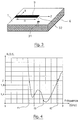
- Figure 1 shows a perspective view of an embodiment of such a radiating element.
- the radiating element according to the invention mainly comprises a substrate plate 1, a supply line 2, and a metallic deposit 3.
- the supply line 2 is located on the underside of the substrate plate 1. It is, for example, a microstrip line of width w. This supply line 2 is connected to a connector 4 (for example of the SMA type) making it possible to connect the radiating element to a traditional coaxial cable (not shown).
- a connector 4 for example of the SMA type
- the metal deposit 3 is located on the upper face of the substrate plate 1 and is T-shaped.
- the horizontal bar of this T of the metallic deposit which is the radiating part 8 of the radiating element, consists of two lateral strands 5,6 separated by a coupling slot 7.
- the length L and the width W of this radiating part 8 determine the mechanical properties specific to the radiating element.
- the two lateral strands 5,6 have the same length L / 2.
- the supply line 2 supplies the radiating part 8 (that is to say the two lateral strands 5, 6) via the coupling slot 7.
- This slot 7 is for example of rectangular shape.
- the vertical bar 11 of the T of the metal deposit 3 extends from the two lateral strands 5, 6 to the connector 4.
- This part 11 of the metal deposit 3 constitutes a ground plane for the supply line 2 situated on the other face of the substrate plate 1.
- the radiating element generates symmetrical currents on the radiating part 8.
- the radiating element of the invention is self-symmetrized.
- the supply line 2 has at its end opposite to that connected to the connector 4, an end portion of length l1 extending beyond the axis of the slot 7. This first length l1 of the end portion of the supply line 2 constitutes a series 9 open-circuit stub.
- the coupling slot 7 has an end portion of length l2 extending beyond the supply line 2. This second length l2 of the end portion of the slot 7 constitutes a parallel stub 10 short-circuited slotted line.
- the radiating element according to the invention comprises, although produced in a printed technologist, a series stub and a parallel stub. These two series and parallel stubs allow the adaptation of the radiating element, according to the principle of double stub adaptation, over a wide frequency band.
- FIG. 2 presents an equivalent electrical diagram of a radiating element according to the invention
- FIG. 5 presents a Smith abacus on which the main ones appear. stages of implementation of this principle.
- FIG. 4 shows a variation curve, as a function of frequency, of the standing wave ratio (ROS) for an example of a radiating element as shown in FIG. 1.
- ROS standing wave ratio
- This curve makes it possible to calculate the passband [f1, f2] of the radiating element, that is to say the frequency band for which the ROS is less than 2.
- This passband can also be expressed as a percentage, obtained by dividing the width (f2-f1) of the passband by the center frequency f3 of this passband.
- the radiating element according to the invention therefore has a wide pass band.
- FIG. 8 presents a variation curve, in a Smith chart, of the input impedance Z e for the previous example of a radiating element.
- variable capacity means are for example, as shown in Figure 3, varactors 31 controlled electronically.
- varying the capacity of these variable capacity means 31 has the same effect as lengthening or decreasing the length of the corresponding stub 9.
- such an adjustment of the adaptation of the radiating element consists in modifying the capacities of the first and / or second means with variable capacity, which is equivalent to a modification of the lengths 11, 12 of stubs.
- Figure 6 shows a second embodiment of a radiating element according to the invention.
- this second embodiment differs from the first only in that it comprises reflection means 61 making it possible to suppress rear radiation from this radiating element.
- the radiation of the dipole alone 62 is omnidirectional except in the axis of the dipole.
- it is desired to direct the radiated energy towards the front of the dipole that is to say on the side opposite to the excitation).
- reflection means 61 aim to increase the directivity of the assembly 62 produced in printed technology (and corresponding to the radiating element of the first embodiment).
- reflection means 61 in the case where they consist of a reflector (in the absence of an ideally undefined defector plane), make it possible to gain approximately 3 dB on the maximum directivity.
- the reflector 61 can have many other shapes than that presented in FIG. 6.
- FIG. 7 shows an example of an array 71 of radiating elements 72 according to the invention.
- the networking of radiating elements also makes it possible to obtain increased directivity and can therefore be combined or not with a reflector.
- the network 71 comprises three radiating elements 72 as well as a reflector 73.
Abstract
Description
Le domaine de l'invention est celui des antennes de télécommunication jusqu'à des fréquences de l'ordre du gigahertz.The field of the invention is that of telecommunications antennas up to frequencies of the order of a gigahertz.
Plus précisément, l'invention concerne un élément rayonnant du type dipôle. En effet, il est encore fréquent, dans les télécommunications hautes fréquences, d'utiliser un tel élément rayonnant du type dipôle en tant qu'antenne émettrice ou réceptrice omnidirectionnelle.More specifically, the invention relates to a radiating element of the dipole type. Indeed, it is still common in high frequency telecommunications to use such a radiating element of the dipole type as an omnidirectional transmitting or receiving antenna.
L'invention a de nombreuses applications, telles que par exemple les relevés de champs, du type mesure de diagrammes d'antennes ou encore mesure de compatibilité électromagnétique.The invention has numerous applications, such as, for example, field readings, of the type of antenna diagram measurement or even measurement of electromagnetic compatibility.
Les éléments rayonnants du type dipôle connus de l'état de la technique sont généralement constitués d'éléments de lignes bifilaires, c'est-à-dire de tiges cylindriques conductrices, alimentés par une ligne d'alimentation.The radiating elements of the dipole type known from the prior art generally consist of elements of two-wire lines, that is to say of conductive cylindrical rods, supplied by a supply line.
Ces éléments rayonnants connus constitués de tiges conductrices présentent des performances relativement large-bande, ce qui les rend utilisables dans de nombreuses applications.These known radiating elements consisting of conductive rods have relatively broadband performance, which makes them usable in many applications.
Toutefois, plusieurs inconvénients sont liés à leur utilisation.However, several drawbacks are linked to their use.
En effet, les lignes d'alimentation (par exemple les lignes coaxiales) sont généralement dissymétriques, alors que les éléments rayonnants sont eux symétriques.In fact, the supply lines (for example the coaxial lines) are generally asymmetrical, while the radiating elements are themselves symmetrical.
Par conséquent, afin que le rayonnement de ces éléments rayonnants soit acceptable, il convient d'utiliser un symétriseur. Un symétriseur se représente traditionnellement comme un transformateur qui fait intervenir des impédances localisées ou distribuées, et permet, lorsqu'il est placé entre un élément rayonnant symétrique et une ligne d'alimentation dissymétrique, de rendre les courants symétriques sur la structure rayonnante. Un tel symétriseur présente l'inconvénient majeur de nécessiter une mise au point toujours délicate.Consequently, in order for the radiation from these radiating elements to be acceptable, a balun should be used. A balun is traditionally represented as a transformer which involves localized or distributed impedances, and allows, when placed between a symmetrical radiating element and an asymmetrical supply line, to make the currents symmetrical on the radiating structure. Such a balun has the major drawback of requiring always delicate focusing.
On connaît également des éléments rayonnants constitués de tiges cylindriques qui sont autosymétrisés, de façon à pouvoir être utilisés sans symétriseur. L'obtention, sur ces éléments rayonnants, d'une telle caractéristique d'autosymétrie ne peut toutefois être obtenue qu'au détriment d'une complexité accrue de leur structure.Radiating elements are also known which consist of cylindrical rods which are self-symmetrized, so that they can be used without a balun. Obtaining such an autosymmetry characteristic on these radiating elements cannot however be obtained only at the expense of an increased complexity of their structure.
Un autre inconvénient de ces éléments rayonnants connus du type dipôle à tiges cylindriques est lié à leur adaptation à la ligne d'alimentation à laquelle ils sont reliés.Another drawback of these known radiating elements of the dipole type with cylindrical rods is linked to their adaptation to the supply line to which they are connected.
En effet, sans une telle adaptation, l'énergie émise par un générateur et transmise à un élément rayonnant par une ligne d'alimentation n'est pas rayonnée par l'élément rayonnant mais renvoyée sur le générateur.Indeed, without such an adaptation, the energy emitted by a generator and transmitted to a radiating element by a supply line is not radiated by the radiating element but returned to the generator.
Généralement, cette adaptation est réalisée grâce à l'utilisation de deux tronçons supplémentaires (ou stubs) placés l'un en série et l'autre en parallèle. On parle alors d'adaptation double stub. Or, la détermination de la longueur de chaque stub (série ou parallèle) étant empirique, l'adaptation nécessite de nombreuses opérations de soudure/dessoudure.Generally, this adaptation is achieved through the use of two additional sections (or stubs) placed one in series and the other in parallel. We then speak of double stub adaptation. Now, the determination of the length of each stub (series or parallel) being empirical, the adaptation requires numerous welding / unsoldering operations.
Enfin, d'une façon générale, ces éléments rayonnants connus du type dipôle à tiges cylindriques présentent un encombrement relativement important ainsi qu'un maniement mécanique parfois difficile.Finally, in general, these known radiating elements of the dipole type with cylindrical rods have a relatively large size as well as sometimes difficult mechanical handling.
L'invention a notamment pour objectif de pallier ces différents inconvénients de l'état de la technique.The invention particularly aims to overcome these various drawbacks of the state of the art.
Plus précisément, un objectif de l'invention est de fournir un élément rayonnant du type dipôle qui possède une large bande passante et des diagrammes omnidirectionnels tout en présentant un faible encombrement et une mise en oeuvre mécanique très simple.More specifically, an objective of the invention is to provide a radiating element of the dipole type which has a large passband and omnidirectional patterns while having a small footprint and a very simple mechanical implementation.
L'invention a également pour objectif de fournir un tel élément rayonnant du type dipôle qui ne nécessite pas l'utilisation conjointe d'un symétriseur.The invention also aims to provide such a radiating element of the dipole type which does not require the joint use of a balun.
Un autre objectif de l'invention est de fournir un tel élément rayonnant du type dipôle qui soit facilement adaptable à la ligne d'alimentation à laquelle il est relié.Another object of the invention is to provide such a radiating element of the dipole type which is easily adaptable to the supply line to which it is connected.
Ces objectifs, ainsi que d'autres qui apparaîtront par la suite, sont atteints selon l'invention à l'aide d'un élément rayonnant adaptable du type dipôle et constitué de:
- une plaque de substrat;
- une ligne d'alimentation située sur la face inférieure de ladite plaque de substrat;
- un dépôt métallique situé sur la face supérieure de ladite plaque de substrat et sensiblement en forme en T : la barre horizontale dudit T étant constituée de deux brins latéraux séparés par une fente de couplage, et la barre verticale dudit T constituant un plan de masse pour ladite ligne d'alimentation, lesdits brins latéraux constituant la partie rayonnante dudit élément rayonnant;
ladite fente présentant une seconde portion d'extrémité dépassant de l'axe de ladite première portion d'extrémité de la ligne d'alimentation d'une seconde longueur variable, et
ledit élément rayonnant comprenant des premiers et/ou des seconds moyens à capacité variable, lesdits premiers moyens à capacité variable étant connectés entre un plan de masse et l'extrémité de ladite ligne d'alimentation située dans ladite première portion d'extrémité, lesdits seconds moyens à capacité variable étant connectés entre un plan de masse et l'extrémité de ladite fente située dans ladite seconde portion d'extrémité.These objectives, as well as others which will appear subsequently, are achieved according to the invention using an adaptable radiating element of the dipole type and consisting of:
- a substrate plate;
- a supply line located on the underside of said substrate plate;
- a metal deposit located on the upper face of said substrate plate and substantially T-shaped: the horizontal bar of said T being consisting of two lateral strands separated by a coupling slot, and the vertical bar of said T constituting a ground plane for said supply line, said lateral strands constituting the radiating part of said radiating element;
said slot having a second end portion projecting from the axis of said first end portion of the supply line of a second variable length, and
said radiating element comprising first and / or second variable capacity means, said first variable capacity means being connected between a ground plane and the end of said supply line located in said first end portion, said second variable capacity means being connected between a ground plane and the end of said slot located in said second end portion.
L'élément rayonnant selon l'invention est donc réalisé en technologie imprimée, ce qui permet un gain de place considérable et un maintien mécanique beaucoup plus aisé.The radiating element according to the invention is therefore produced in printed technology, which allows a considerable saving of space and a much easier mechanical maintenance.
Par ailleurs, le dépôt métallique comprend d'une part les deux brins latéraux (formant la barre horizontale du T) qui constituent le dipôle proprement dit, et d'autre part un prolongement, selon une direction orthogonale à ces brins latéraux (prolongement formant la barre verticale du T), qui constitue le plan de masse pour la ligne d'alimentation.Furthermore, the metal deposit comprises on the one hand the two lateral strands (forming the horizontal bar of the T) which constitute the dipole proper, and on the other hand an extension, in a direction orthogonal to these lateral strands (extension forming the vertical bar of T), which constitutes the ground plane for the supply line.
Ainsi, la présence de ce plan de masse associé à la ligne d'alimentation assure que l'alimentation est autosymétrisée. En d'autres termes, l'élément rayonnant selon l'invention ne nécessite pas l'utilisation conjointe d'un symétriseur.Thus, the presence of this ground plane associated with the supply line ensures that the supply is autosymmetrized. In other words, the radiating element according to the invention does not require the joint use of a balun.
De plus, la ligne d'alimentation alimente les deux brins latéraux par l'intermédiaire de la fente de couplage.In addition, the supply line feeds the two side strands via the coupling slot.
Afin de pouvoir mettre en oeuvre le principe connu de l'adaptation double stubs dans le cas d'un élément rayonnant réalisé en technologie imprimée, l'invention propose une réalisation originale des stubs ou tronçons d'adaptation série et parallèle. En effet, selon l'invention :
- le stub série est constitué de la première portion d'extrémité de la ligne d'alimentation qui dépasse de l'axe de la fente, et possède la première longueur variable ; et
- le stub parallèle est constitué de la seconde portion d'extrémité de la fente qui dépasse de la première portion d'extrémité de la ligne d'alimentation, et possède la seconde longueur variable.
- the series stub consists of the first end portion of the supply line which protrudes from the axis of the slot, and has the first variable length; and
- the parallel stub consists of the second end portion of the slot which protrudes from the first end portion of the supply line, and has the second variable length.
Un choix convenable de ces première et seconde longueurs variables permet d'adapter l'élément rayonnant sur une large bande.A suitable choice of these first and second variable lengths makes it possible to adapt the radiating element over a wide band.
L'élément rayonnant selon l'invention est également adaptable grâce aux premiers et/ou seconds moyens à capacité variable. En effet, la modification de la capacité des premiers moyens a le même effet qu'un allongement ou une diminution "physique" (c'est-à-dire réelle) de la première longueur variable. De même, on peut agir sur la seconde longueur variable en modifiant la capacité des seconds moyens à capacité variable.The radiating element according to the invention is also adaptable thanks to the first and / or second means with variable capacity. Indeed, the modification of the capacity of the first means has the same effect as an elongation or a "physical" (that is to say real) reduction in the first variable length. Similarly, one can act on the second variable length by modifying the capacity of the second variable capacity means.
Avantageusement, ladite fente est de forme rectangulaire.Advantageously, said slot is of rectangular shape.
Préférentiellement, la longueur cumulée de l'ensemble desdits deux brins latéraux est sensiblement égale à la moitié de la longueur d'onde de fonctionnement dudit élément rayonnant.Preferably, the cumulative length of all of said two lateral strands is substantially equal to half the operating wavelength of said radiating element.
Ainsi, on obtient des valeurs classiques d'impédance de rayonnement pour les deux brins latéraux constituant le dipôle proprement dit.Thus, conventional values of radiation impedance are obtained for the two lateral strands constituting the actual dipole.
Avantageusement, lesdits deux brins latéraux sont de même longueur.Advantageously, said two lateral strands are of the same length.
De façon avantageuse, ladite ligne d'alimentation est une ligne microruban.Advantageously, said supply line is a microstrip line.
Dans un mode de réalisation préférentiel de l'invention, l'élément rayonnant comprend également des moyens de réflexion permettant de supprimer un rayonnement arrière dudit élément rayonnant.In a preferred embodiment of the invention, the radiating element also comprises reflection means making it possible to suppress rear radiation from said radiating element.
De cette façon, on dirige vers l'avant l'énergie rayonnée par l'élément rayonnant. Ceci permet de gagner à peu près 3 dB sur le maximum de directivité de l'élément rayonnant.In this way, the energy radiated by the radiating element is directed forward. This allows to gain approximately 3 dB on the maximum directivity of the radiating element.
L'invention concerne également un réseau d'éléments rayonnants comprenant au moins deux éléments rayonnants selon l'invention.The invention also relates to a network of radiating elements comprising at least at least two radiating elements according to the invention.
Enfin, l'invention concerne aussi un procédé d'ajustement de l'adaptation d'un élément rayonnant, caractérisé en ce qu'il comprend une première étape d'ajustement de ladite première longueur variable et une seconde étape d'ajustement de ladite seconde longueur variable.Finally, the invention also relates to a method of adjusting the adaptation of a radiating element, characterized in that it comprises a first step of adjusting said first variable length and a second step of adjusting said second variable length.
En effet, il est toujours nécessaire d'ajuster les valeurs des première et seconde longueurs variables (des stubs série et parallèle) que le principe de l'adaptation double stub permet de calculer théoriquement.Indeed, it is always necessary to adjust the values of the first and second variable lengths (of the serial and parallel stubs) that the principle of the double stub adaptation allows to calculate theoretically.
Dans un mode de réalisation du procédé selon l'invention, ladite première étape d'ajustement de la première longueur variable consiste à modifier la valeur de la capacité de premiers moyens à capacité variable connectés entre un plan de masse et l'extrémité de la ligne d'alimentation située dans la première portion d'extrémité,
et ladite seconde étape d'ajustement de la seconde longueur variable consiste à modifier la valeur de la capacité de seconds moyens à capacité variable connectés entre un plan de masse et l'extrémité de la fente située dans la seconde portion d'extrémité.In an embodiment of the method according to the invention, said first step of adjusting the first variable length consists in modifying the value of the capacity of first means with variable capacity connected between a ground plane and the end of the line feed located in the first end portion,
and said second step of adjusting the second variable length consists in modifying the value of the capacity of second variable capacity means connected between a ground plane and the end of the slot located in the second end portion.
Avantageusement, ladite première étape d'ajustement de la première longueur variable consiste également à découper partiellement ladite première portion d'extrémité de la ligne d'alimentation,
et ladite seconde étape d'ajustement de la seconde longueur variable consiste également à boucher partiellement ladite seconde portion d'extrémité de la fente avec un matériau conducteur.Advantageously, said first step of adjusting the first variable length also consists in partially cutting said first end portion of the supply line,
and said second step of adjusting the second variable length also includes partially plugging said second end portion of the slot with a conductive material.
D'autres caractéristiques et avantages de l'invention apparaîtront à la lecture de la description suivante d'un mode de réalisation préférentiel de l'invention, donné à titre d'exemple indicatif et non limitatif, et des dessins annexés, dans lesquels :
- la figure 1 présente une vue en perspective d'un mode de réalisation préférentiel de l'élément rayonnant selon l'invention;
- la figure 2 présente un schéma électrique équivalent d'un élément rayonnant selon l'invention;
- la figure 3 présente un exemple de moyens à capacité variable pouvant être mis en oeuvre dans un élément rayonnant selon l'invention;
- la figure 4 présente une courbe de variation, en fonction de la fréquence, du rapport d'onde stationnaire pour un exemple d'élément rayonnant selon l'invention;
- la figure 5 présente, sur un abaque de Smith, le principe de l'adaptation double stub;
- la figure 6 présente un second mode de réalisation d'un élément rayonnant selon l'invention comprenant un réflecteur;
- la figure 7 présente un exemple de réseau comprenant plusieurs éléments rayonnants selon l'invention ; et
- la figure 8 présente une courbe de variation, dans un abaque de Smith, de l'impédance d'entrée pour un exemple d'élément rayonnant selon l'invention.
- Figure 1 shows a perspective view of a preferred embodiment of the radiating element according to the invention;
- FIG. 2 presents an equivalent electrical diagram of a radiating element according to the invention;
- FIG. 3 shows an example of variable capacity means which can be used in a radiating element according to the invention;
- FIG. 4 shows a variation curve, as a function of frequency, of the standing wave ratio for an example of a radiating element according to the invention;
- FIG. 5 presents, on a Smith chart, the principle of the double stub adaptation;
- FIG. 6 shows a second embodiment of a radiating element according to the invention comprising a reflector;
- FIG. 7 shows an example of a network comprising several radiating elements according to the invention; and
- FIG. 8 presents a variation curve, in a Smith chart, of the input impedance for an example of radiating element according to the invention.
L'invention concerne donc un élément rayonnant du type dipôle réalisé en technologie imprimée. La figure 1 présente une vue en perspective d'un mode de réalisation d'un tel élément rayonnant.The invention therefore relates to a radiating element of the dipole type produced in printed technology. Figure 1 shows a perspective view of an embodiment of such a radiating element.
Comme montré sur cette figure 1, l'élément rayonnant selon l'invention comprend principalement une plaque de substrat 1, une ligne d'alimentation 2, et un dépôt métallique 3.As shown in this FIG. 1, the radiating element according to the invention mainly comprises a
La plaque de substrat 1 est par exemple un substrat Duroïd du type verte téflon, possédant une permittivité relative εr = 2,2 et une épaisseur h = 0,76 mm.The
La ligne d'alimentation 2 est située sur la face inférieure de la plaque de substrat 1. Il s'agit par exemple d'une ligne microruban de largeur w. Cette ligne d'alimentation 2 est reliée à un connecteur 4 (par exemple de type SMA) permettant de relier l'élément rayonnant à un câble coaxial traditionnel (non représenté).The
Le dépôt métallique 3 est situé sur la face supérieure de la plaque de substrat 1 et est en forme de T.The
La barre horizontale de ce T du dépôt métallique, qui est la partie rayonnante 8 de l'élément rayonnant, est constituée de deux brins latéraux 5,6 séparés par une fente de couplage 7. La longueur L de cette partie rayonnante 8 est choisie égale à la moitié de la longueur d'onde de fonctionnement, de façon à avoir une valeur classique d'impédance, à savoir ![]()
![]()
Dans l'exemple présenté, les deux brins latéraux 5,6 sont de même longueur L/2.In the example presented, the two
La ligne d'alimentation 2 alimente la partie rayonnante 8 (c'est-à-dire les deux brins latéraux 5, 6) par l'intermédiaire de la fente de couplage 7. Cette fente 7 est par exemple de forme rectangulaire.The
La barre verticale 11 du T du dépôt métallique 3 s'étend à partir des deux brins latéraux 5, 6 jusqu'au connecteur 4.The
Cette partie 11 du dépôt métallique 3 constitue un plan de masse pour la ligne d'alimentation 2 située sur l'autre face de la plaque de substrat 1. De cette façon, l'élément rayonnant génère des courants symétriques sur la partie rayonnante 8. En d'autres termes, l'élément rayonnant de l'invention est autosymétrisé.This
La ligne d'alimentation 2 possède à son extrémité opposée à celle reliée au connecteur 4, une portion d'extrémité de longueur l1 s'étendant au delà de l'axe de la fente 7. Cette première longueur l1 de la portion d'extrémité de la ligne d'alimentation 2 constitue un stub série 9 circuit-ouvert.The
La fente de couplage 7 possède une portion d'extrémité de longueur l2 s'étendant au delà de la ligne d'alimentation 2. Cette seconde longueur l2 de la portion d'extrémité de la fente 7 constitue un stub parallèle 10 court-circuit en ligne à fente.The
Ainsi, l'élément rayonnant selon l'invention comprend, bien que réalisé en technologue imprimée, un stub série et un stub parallèle. Ces deux stubs série et parallèle permettent l'adaptation de l'élément rayonnant, selon le principe de l'adaptation double stub, sur une large bande de fréquences.Thus, the radiating element according to the invention comprises, although produced in a printed technologist, a series stub and a parallel stub. These two series and parallel stubs allow the adaptation of the radiating element, according to the principle of double stub adaptation, over a wide frequency band.
Le principe de l'adaptation double stub est maintenant expliqué brièvement en relation avec la figure 2, qui présente un schéma électrique équivalent d'un élément rayonnant selon l'invention, et la figure 5 qui présente un abaque de Smith sur lequel apparaissent les principales étapes de mise en oeuvre de ce principe.The principle of the double stub adaptation is now briefly explained in relation to FIG. 2, which presents an equivalent electrical diagram of a radiating element according to the invention, and FIG. 5 which presents a Smith abacus on which the main ones appear. stages of implementation of this principle.
Comme cela apparaît sur la figure 2 :
- la partie rayonnante présente une impédance

- le stub série de longueur l1 présente une réactance ajustable X₁ (X₁ étant fonction de l1) ; et
- le stub parallèle de longueur l2 présente une susceptance ajustable B₂ (B₂ étant fonction de l2).
- the radiating part has an impedance
- the stub series of length l1 has an adjustable reactance X₁ (X₁ being a function of l1); and
- the parallel stub of length l2 has an adjustable susceptance B₂ (B₂ being a function of l2).
L'adaptation de l'élément rayonnant consiste à rendre l'impédance d'entrée Ze de cet élément rayonnant égale à l'impédance caractéristique Zc du câble coaxial. Typiquement, on a Zc = 50 Ω.The adaptation of the radiating element consists in making the input impedance Z e of this radiating element equal to the characteristic impedance Z c of the coaxial cable. Typically, we have Z c = 50 Ω.
Cette adaptation (c'est-à-dire l'égalité Ze = Zc) est réalisée grâce à un choix convenable de la réactance X₁ et de la susceptance B₂, c'est-à-dire des longueurs l1 et l2 des stubs série et parallèle.This adaptation (that is to say the equality Z e = Z c ) is achieved by means of a suitable choice of the reactance X₁ and the susceptance B₂, that is to say of the lengths l1 and l2 of the stubs series and parallel.
Comme présenté en relation avec la figure 5, l'abaque de Smith permet de déterminer les valeurs acceptables de X₁ et B₂, à partir de la valeur de ![]()
![]()
Les étapes de calcul sont les suivantes :
- on construit le cercle G = 1 décalé de 180 degrés, pour le passage en admittance :
- à partir du point Yr, on ajoute j B₂ en se déplaçant le long du cercle à conductance constante, jusqu'à l'intersection avec le cercle G = 1 décalé. La nouvelle valeur de l'admittance est Y'L ou Y''L;
- on prend le symétrique de Y'L ou Y''L pour avoir la nouvelle valeur en impédance (à savoir Z'L ou Z''L) qui se situe comme on l'a imposé sur le cercle G = 1 ;
- on soustrait la réactance j X' ou j X'' (puisque l'origine de l'abaque correspond à une condition d'adaptation parfaite). La valeur X₂ est donc X' ou X''.
- we construct the circle G = 1 offset by 180 degrees, for the transition to admittance:
- from the point Y r , we add j B₂ by moving along the circle with constant conductance, until the intersection with the offset circle G = 1. The new admittance value is Y ' L or Y''L;
- we take the symmetric of Y ' L or Y'' L to have the new impedance value (namely Z' L or Z '' L ) which is located as we imposed on the circle G = 1;
- we subtract the reactance j X 'or j X''(since the origin of the abacus corresponds to a perfect adaptation condition). The value X₂ is therefore X 'or X''.
Il est à noter que la plus grande bande passante est obtenue quand les éléments réactifs sont choisis les plus petits possible, de sorte que le facteur de qualité du circuit d'adaptation reste faible.It should be noted that the greatest bandwidth is obtained when the reactive elements are chosen to be as small as possible, so that the quality factor of the adaptation circuit remains low.
La figure 4 présente une courbe de variation, en fonction de la fréquence, du rapport d'onde stationnaire (ROS) pour un exemple d'élément rayonnant tel que montré sur la figure 1.FIG. 4 shows a variation curve, as a function of frequency, of the standing wave ratio (ROS) for an example of a radiating element as shown in FIG. 1.
Dans cet exemple, l'élément rayonnant est caractérisé par les grandeurs géométriques suivantes :
- plaque de substrat 1 Duroïd type verte téflon, de permittivité relative εr = 2,2 et d'épaisseur h = 0,76 mm ;
ligne d'alimentation 2 de largeur w = 2,16 mm ;- partie rayonnante (dipôle) 8 de longueur L = 55 mm et de largeur W = 10 mm ;
- stub série de longueur l1 = 10,5 mm ; et
- stub parallèle de longueur l2 = 10 mm.
-
substrate plate 1 Duroid green teflon type, with relative permittivity ε r = 2.2 and thickness h = 0.76 mm; -
supply line 2 of width w = 2.16 mm; - radiating part (dipole) 8 of length L = 55 mm and width W = 10 mm;
- stub series of length l1 = 10.5 mm; and
- parallel stub of length l2 = 10 mm.
Cette courbe permet de calculer la bande passante [f₁, f₂] de l'élément rayonnant, c'est-à-dire la bande de fréquences pour lesquelles le ROS est inférieur à 2. Cette bande passante peut également s'exprimer en pourcentage, obtenu par division de la largeur (f₂-f₁) de la bande passante par la fréquence centrale f₃ de cette bande passante.This curve makes it possible to calculate the passband [f₁, f₂] of the radiating element, that is to say the frequency band for which the ROS is less than 2. This passband can also be expressed as a percentage, obtained by dividing the width (f₂-f₁) of the passband by the center frequency f₃ of this passband.
Dans cet exemple, la bande passante est sensiblement comprise entre f₁ = 1,83 GHz et f₂ = 2,84 GHz. Avec une fréquence centrale f₃ = 2,33 GHz, cette bande passante est égale à 44 %. L'élément rayonnant selon l'invention possède donc une large bande passante.In this example, the bandwidth is substantially between f₁ = 1.83 GHz and f₂ = 2.84 GHz. With a central frequency f₃ = 2.33 GHz, this bandwidth is equal to 44%. The radiating element according to the invention therefore has a wide pass band.
La figure 8 présente une courbe de variation, dans un abaque de Smith, de l'impédance d'entrée Ze pour l'exemple précédent d'élément rayonnant.FIG. 8 presents a variation curve, in a Smith chart, of the input impedance Z e for the previous example of a radiating element.
Aux fréquences f₁, f₂ et f₃ définissant la bande passante, on a les impédances d'entrée Ze1, Ze2 et Ze3, avec :
![]()
![]()
![]()
At frequencies f₁, f₂ and f₃ defining the passband, we have the input impedances Z e1 , Z e2 and Z e3 , with:
![]()
![]()
![]()
On remarquera la présence de la boucle qui garantit une faible dispersion en fréquence et traduit l'efficacité de l'adaptation.Note the presence of the loop which guarantees low frequency dispersion and reflects the efficiency of the adaptation.
Lors de la phase expérimentale, il peut exister une légère désadaptation de l'élément rayonnant et il convient alors d' ajuster les longueurs l1, l2 des stubs série et parallèle, ces longueurs l1, l2 étant calculées préalablement grâce au principe de l'adaptation double stub décrite précédemment.During the experimental phase, there may be a slight mismatch of the radiating element and it is then necessary to adjust the lengths l1, l2 of the series and parallel stubs, these lengths l1, l2 being calculated beforehand thanks to the principle of adaptation double stub described above.
Pour permettre un tel ajustement des longueurs l1, l2 l'élément rayonnant comprend :
- des premiers moyens 31 (figure 3) à capacité variable connectés entre un plan de masse (par exemple un des brins latéraux 6) et l'extrémité 32 de la portion d'extrémité de la ligne d'alimentation constituant le
stub série 9 ; et/ou - des seconds moyens (non représentés) à capacité variable connectés entre un plan de masse et l'extrémité de la fente constituant le stub parallèle.
- first means 31 (FIG. 3) with variable capacity connected between a ground plane (for example one of the side strands 6) and the
end 32 of the end portion of the supply line constituting theseries stub 9; and or - second variable capacity means (not shown) connected between a ground plane and the end of the slot constituting the parallel stub.
Ces premiers et/ou seconds moyens à capacité variable sont par exemple, comme présenté à la figure 3, des varactors 31 commandés électroniquement. Ainsi, la variation de la capacité de ces moyens 31 à capacité variable a le même effet qu'un allongement ou une diminution de la longueur du stub correspondant 9.These first and / or second variable capacity means are for example, as shown in Figure 3,
Ainsi, un tel ajustement de l'adaptation de l'élément rayonnant consiste à modifier les capacités des premiers et/ou seconds moyens à capacité variable, ce qui est équivalent à une modification des longueurs l1, l2 de stubs.Thus, such an adjustment of the adaptation of the radiating element consists in modifying the capacities of the first and / or second means with variable capacity, which is equivalent to a modification of the
Ce procédé d'ajustement "électronique" peut éventuellement être complété par un ajustement "manuel" tel que :
- l'ajustement de la longueur l1 du stub série consiste également à découper partiellement la portion d'extrémité de la ligne d'alimentation dépassant de la fente ; et
- l'ajustement de la longueur l2 du stub parallèle consiste également à boucher partiellement, avec un matériau conducteur, la portion d'extrémité de la fente dépassant de la ligne d'alimentation.
- adjusting the
length 11 of the series stub also consists in partially cutting the end portion of the supply line projecting from the slot; and - adjusting the
length 12 of the parallel stub also consists in partially plugging, with a conductive material, the end portion of the slot protruding from the supply line.
La figure 6 présente un second mode de réalisation d'un élément rayonnant selon l'invention. En fait, ce second mode de réalisation se différencie du premier uniquement en ce qu'il comprend des moyens 61 de réflexion permettant de supprimer un rayonnement arrière de cet élément rayonnant. En effet, le rayonnement du dipôle seul 62 est omnidirectionnel excepté dans l'axe du dipôle. Or pour certaines applications, on souhaite diriger l'énergie rayonnée vers l'avant du dipôle (c'est-à-dire du côté opposé à l'excitation).Figure 6 shows a second embodiment of a radiating element according to the invention. In fact, this second embodiment differs from the first only in that it comprises reflection means 61 making it possible to suppress rear radiation from this radiating element. Indeed, the radiation of the dipole alone 62 is omnidirectional except in the axis of the dipole. However, for certain applications, it is desired to direct the radiated energy towards the front of the dipole (that is to say on the side opposite to the excitation).
Ces moyens 61 de réflexion visent à accroître la directivité de l'ensemble 62 réalisé en technologie imprimée (et correspondant à l'élément rayonnant du premier mode de réalisation).These reflection means 61 aim to increase the directivity of the
Ces moyens 61 de réflexion, dans le cas où ils sont constitués d'un réflecteur (à défaut d'un plan défecteur idéalement indéfini), permettent de gagner environ 3 dB sur le maximum de directivité.These reflection means 61, in the case where they consist of a reflector (in the absence of an ideally undefined defector plane), make it possible to gain approximately 3 dB on the maximum directivity.
Il est clair que le réflecteur 61 peut posséder de nombreuses autres formes que celle présentée sur la figure 6.It is clear that the
La figure 7 présente un exemple de réseau 71 d'éléments rayonnants 72 selon l'invention. La mise en réseau d'éléments rayonnants permet également d'obtenir une directivité accrue et peut donc être combinée ou non à un réflecteur. Dans cet exemple, le réseau 71 comprend trois éléments rayonnants 72 ainsi qu'un réflecteur 73.FIG. 7 shows an example of an
Claims (10)
en ce que ladite fente (7) présente une seconde portion d'extrémité (10) dépassant de l'axe de ladite première portion d'extrémité (9) de la ligne d'alimentation d'une seconde longueur variable (l2),
et en ce qu'il comprend des premiers (31) et/ou des seconds moyens à capacité variable, lesdits premiers moyens (31) à capacité variable étant connectés entre un plan de masse (6) et l'extrémité (32) de ladite ligne d'alimentation (3) située dans ladite première portion d'extrémité (9), lesdits seconds moyens à capacité variable étant connectés entre un plan de masse et l'extrémité de ladite fente située dans ladite seconde portion d'extrémité.Adaptable radiating element, of the dipole type and consisting of:
in that said slot (7) has a second end portion (10) projecting from the axis of said first end portion (9) of the supply line of a second variable length (12),
and in that it comprises first (31) and / or second variable capacity means, said first variable capacity means (31) being connected between a ground plane (6) and the end (32) of said supply line (3) located in said first end portion (9), said second variable capacity means being connected between a ground plane and the end of said slot located in said second end portion.
et en ce que ladite seconde étape d'ajustement de la seconde longueur variable consiste à modifier la valeur de la capacité de seconds moyens à capacité variable connectés entre un plan de masse et l'extrémité de la fente située dans la seconde portion d'extrémité.Method according to claim 8, characterized in that said first step of adjusting the first variable length consists in modifying the value of the capacity of first variable capacity means connected between a ground plane and the end of the line of feed located in the first end portion,
and in that said second step of adjusting the second variable length consists in modifying the value of the capacity of second variable capacity means connected between a ground plane and the end of the slot located in the second end portion .
et en ce que ladite seconde étape d'ajustement de la seconde longueur variable consiste également à boucher partiellement ladite seconde portion d'extrémité de la fente avec un matériau conducteur.Method according to claim 9, characterized in that said first step of adjusting the first variable length also consists in partially cutting said first end portion of the supply line,
and in that said second step of adjusting the second variable length also consists in partially plugging said second end portion of the slot with a conductive material.
Applications Claiming Priority (2)
| Application Number | Priority Date | Filing Date | Title |
|---|---|---|---|
| FR9314276 | 1993-11-24 | ||
| FR9314276A FR2713020B1 (en) | 1993-11-24 | 1993-11-24 | Radiating element of the dipole type produced in printed technology, matching adjustment process and corresponding network. |
Publications (2)
| Publication Number | Publication Date |
|---|---|
| EP0654845A1 true EP0654845A1 (en) | 1995-05-24 |
| EP0654845B1 EP0654845B1 (en) | 1999-01-20 |
Family
ID=9453343
Family Applications (1)
| Application Number | Title | Priority Date | Filing Date |
|---|---|---|---|
| EP19940460042 Expired - Lifetime EP0654845B1 (en) | 1993-11-24 | 1994-11-18 | Adaptable dipole radiating element in printed circuit technology, method for adjustment of the adaptation and corresponding array |
Country Status (3)
| Country | Link |
|---|---|
| EP (1) | EP0654845B1 (en) |
| DE (1) | DE69416088T2 (en) |
| FR (1) | FR2713020B1 (en) |
Cited By (1)
| Publication number | Priority date | Publication date | Assignee | Title |
|---|---|---|---|---|
| EP1073143A1 (en) * | 1999-07-30 | 2001-01-31 | France Telecom | Dual polarisation printed antenna and corresponding array |
Families Citing this family (3)
| Publication number | Priority date | Publication date | Assignee | Title |
|---|---|---|---|---|
| FR2854739A1 (en) * | 2003-05-06 | 2004-11-12 | France Telecom | ANTENNA, SENSOR OR ELECTROMAGNETIC PROBE |
| FR2882468A1 (en) | 2005-02-18 | 2006-08-25 | France Telecom | PRINTED DIPOLE ANTENNA MULTIBAND |
| CN102067380A (en) * | 2008-05-19 | 2011-05-18 | 盖尔创尼克斯有限公司 | Conformable antenna |
Citations (3)
| Publication number | Priority date | Publication date | Assignee | Title |
|---|---|---|---|---|
| US3845490A (en) * | 1973-05-03 | 1974-10-29 | Gen Electric | Stripline slotted balun dipole antenna |
| US4114163A (en) * | 1976-12-06 | 1978-09-12 | The United States Of America As Represented By The Secretary Of The Army | L-band radar antenna array |
| US4825220A (en) * | 1986-11-26 | 1989-04-25 | General Electric Company | Microstrip fed printed dipole with an integral balun |
-
1993
- 1993-11-24 FR FR9314276A patent/FR2713020B1/en not_active Expired - Fee Related
-
1994
- 1994-11-18 EP EP19940460042 patent/EP0654845B1/en not_active Expired - Lifetime
- 1994-11-18 DE DE1994616088 patent/DE69416088T2/en not_active Expired - Fee Related
Patent Citations (3)
| Publication number | Priority date | Publication date | Assignee | Title |
|---|---|---|---|---|
| US3845490A (en) * | 1973-05-03 | 1974-10-29 | Gen Electric | Stripline slotted balun dipole antenna |
| US4114163A (en) * | 1976-12-06 | 1978-09-12 | The United States Of America As Represented By The Secretary Of The Army | L-band radar antenna array |
| US4825220A (en) * | 1986-11-26 | 1989-04-25 | General Electric Company | Microstrip fed printed dipole with an integral balun |
Non-Patent Citations (1)
| Title |
|---|
| EDWARD AND REES: "A Broadband Printed Dipole with Integrated Balun", MICROWAVE JOURNAL., vol. 30, no. 5, DEDHAM US, pages 339 - 344 * |
Cited By (3)
| Publication number | Priority date | Publication date | Assignee | Title |
|---|---|---|---|---|
| EP1073143A1 (en) * | 1999-07-30 | 2001-01-31 | France Telecom | Dual polarisation printed antenna and corresponding array |
| FR2797098A1 (en) * | 1999-07-30 | 2001-02-02 | France Telecom | BI-POLARIZATION PRINTED ANTENNA AND CORRESPONDING ANTENNA ARRAY |
| US6281849B1 (en) | 1999-07-30 | 2001-08-28 | France Telecom | Printed bi-polarization antenna and corresponding network of antennas |
Also Published As
| Publication number | Publication date |
|---|---|
| FR2713020A1 (en) | 1995-06-02 |
| DE69416088T2 (en) | 1999-09-16 |
| FR2713020B1 (en) | 1996-02-23 |
| DE69416088D1 (en) | 1999-03-04 |
| EP0654845B1 (en) | 1999-01-20 |
Similar Documents
| Publication | Publication Date | Title |
|---|---|---|
| EP0714151B1 (en) | Broadband monopole antenna in uniplanar printed circuit technology and transmit- and/or receive device with such an antenna | |
| CA1291560C (en) | Helicoidal antenna and method for fabricating said antenna | |
| EP0888647B1 (en) | Helix antenna with a built-in broadband power supply, and manufacturing methods therefor | |
| EP0667984B1 (en) | Monopolar wire-plate antenna | |
| FR2810163A1 (en) | IMPROVEMENT TO ELECTROMAGNETIC WAVE EMISSION / RECEPTION SOURCE ANTENNAS | |
| FR2752646A1 (en) | PLANE PRINTED ANTENNA WITH OVERLAPPING ELEMENTS SHORT CIRCUITS | |
| FR2556510A1 (en) | PLANE PERIODIC ANTENNA | |
| EP0542595A1 (en) | Microstrip antenna device especially for satellite telephone transmissions | |
| EP2710676B1 (en) | Radiating element for an active array antenna consisting of elementary tiles | |
| EP0243289A1 (en) | Plate antenna with two crossed polarizations | |
| FR2669776A1 (en) | SLOTTED MICROWAVE ANTENNA WITH LOW THICKNESS STRUCTURE. | |
| FR2652453A1 (en) | COAXIAL ANTENNA HAVING A PROGRESSIVE WAVE POWER TYPE. | |
| EP0082751B1 (en) | Microwave radiator and its use in an electronically scanned antenna | |
| EP3235058B1 (en) | Wire-plate antenna having a capacitive roof incorporating a slot between the feed probe and the short-circuit wire | |
| FR2746548A1 (en) | HELICAL ANTENNA WITH INTEGRATED DUPLEXING MEANS, AND MANUFACTURING METHODS THEREOF | |
| WO2016023919A1 (en) | Multiband source with coaxial horn having monopulse tracking systems for a reflector antenna | |
| EP0654845B1 (en) | Adaptable dipole radiating element in printed circuit technology, method for adjustment of the adaptation and corresponding array | |
| EP0605338A1 (en) | Patch antenna with dual polarisation and corresponding device for transmission/reception | |
| EP1540768A1 (en) | Broadband helical antenna | |
| WO1993000718A1 (en) | Tunable microwave bandstop filter device | |
| EP0477102B1 (en) | Directional network with adjacent radiator elements for radio communication system and unit with such a directional network | |
| EP0991135B1 (en) | Selective antenna with frequency switching | |
| FR2705167A1 (en) | Small-sized, wide-band patch antenna, and corresponding transmitting/receiving device | |
| EP0326498A1 (en) | Resonant circuit and filter using it | |
| FR2729011A1 (en) | Dual polarisation antenna network |
Legal Events
| Date | Code | Title | Description |
|---|---|---|---|
| PUAI | Public reference made under article 153(3) epc to a published international application that has entered the european phase |
Free format text: ORIGINAL CODE: 0009012 |
|
| AK | Designated contracting states |
Kind code of ref document: A1 Designated state(s): DE GB |
|
| 17P | Request for examination filed |
Effective date: 19950830 |
|
| GRAG | Despatch of communication of intention to grant |
Free format text: ORIGINAL CODE: EPIDOS AGRA |
|
| 17Q | First examination report despatched |
Effective date: 19980122 |
|
| GRAG | Despatch of communication of intention to grant |
Free format text: ORIGINAL CODE: EPIDOS AGRA |
|
| GRAH | Despatch of communication of intention to grant a patent |
Free format text: ORIGINAL CODE: EPIDOS IGRA |
|
| GRAH | Despatch of communication of intention to grant a patent |
Free format text: ORIGINAL CODE: EPIDOS IGRA |
|
| GRAA | (expected) grant |
Free format text: ORIGINAL CODE: 0009210 |
|
| AK | Designated contracting states |
Kind code of ref document: B1 Designated state(s): DE GB |
|
| REF | Corresponds to: |
Ref document number: 69416088 Country of ref document: DE Date of ref document: 19990304 |
|
| PG25 | Lapsed in a contracting state [announced via postgrant information from national office to epo] |
Ref country code: DE Free format text: LAPSE BECAUSE OF FAILURE TO SUBMIT A TRANSLATION OF THE DESCRIPTION OR TO PAY THE FEE WITHIN THE PRESCRIBED TIME-LIMIT Effective date: 19990421 |
|
| GBT | Gb: translation of ep patent filed (gb section 77(6)(a)/1977) |
Effective date: 19990416 |
|
| PLBE | No opposition filed within time limit |
Free format text: ORIGINAL CODE: 0009261 |
|
| STAA | Information on the status of an ep patent application or granted ep patent |
Free format text: STATUS: NO OPPOSITION FILED WITHIN TIME LIMIT |
|
| 26N | No opposition filed | ||
| REG | Reference to a national code |
Ref country code: GB Ref legal event code: IF02 |
|
| PGFP | Annual fee paid to national office [announced via postgrant information from national office to epo] |
Ref country code: GB Payment date: 20061026 Year of fee payment: 13 |
|
| PGFP | Annual fee paid to national office [announced via postgrant information from national office to epo] |
Ref country code: DE Payment date: 20061108 Year of fee payment: 13 |
|
| GBPC | Gb: european patent ceased through non-payment of renewal fee |
Effective date: 20071118 |
|
| PG25 | Lapsed in a contracting state [announced via postgrant information from national office to epo] |
Ref country code: DE Free format text: LAPSE BECAUSE OF NON-PAYMENT OF DUE FEES Effective date: 20080603 |
|
| PG25 | Lapsed in a contracting state [announced via postgrant information from national office to epo] |
Ref country code: GB Free format text: LAPSE BECAUSE OF NON-PAYMENT OF DUE FEES Effective date: 20071118 |