EP0720096A2 - Apparatus and method for providing continuity of operation in a system - Google Patents
Apparatus and method for providing continuity of operation in a system Download PDFInfo
- Publication number
- EP0720096A2 EP0720096A2 EP96103428A EP96103428A EP0720096A2 EP 0720096 A2 EP0720096 A2 EP 0720096A2 EP 96103428 A EP96103428 A EP 96103428A EP 96103428 A EP96103428 A EP 96103428A EP 0720096 A2 EP0720096 A2 EP 0720096A2
- Authority
- EP
- European Patent Office
- Prior art keywords
- volatile memory
- system state
- demand
- coupled
- processing
- Prior art date
- Legal status (The legal status is an assumption and is not a legal conclusion. Google has not performed a legal analysis and makes no representation as to the accuracy of the status listed.)
- Granted
Links
Images


Classifications
-
- G—PHYSICS
- G06—COMPUTING; CALCULATING OR COUNTING
- G06F—ELECTRIC DIGITAL DATA PROCESSING
- G06F1/00—Details not covered by groups G06F3/00 - G06F13/00 and G06F21/00
- G06F1/26—Power supply means, e.g. regulation thereof
- G06F1/30—Means for acting in the event of power-supply failure or interruption, e.g. power-supply fluctuations
-
- G—PHYSICS
- G06—COMPUTING; CALCULATING OR COUNTING
- G06F—ELECTRIC DIGITAL DATA PROCESSING
- G06F11/00—Error detection; Error correction; Monitoring
- G06F11/07—Responding to the occurrence of a fault, e.g. fault tolerance
- G06F11/14—Error detection or correction of the data by redundancy in operation
- G06F11/1402—Saving, restoring, recovering or retrying
- G06F11/1415—Saving, restoring, recovering or retrying at system level
- G06F11/1441—Resetting or repowering
-
- G—PHYSICS
- G06—COMPUTING; CALCULATING OR COUNTING
- G06F—ELECTRIC DIGITAL DATA PROCESSING
- G06F9/00—Arrangements for program control, e.g. control units
- G06F9/06—Arrangements for program control, e.g. control units using stored programs, i.e. using an internal store of processing equipment to receive or retain programs
- G06F9/44—Arrangements for executing specific programs
- G06F9/4401—Bootstrapping
- G06F9/4418—Suspend and resume; Hibernate and awake
-
- Y—GENERAL TAGGING OF NEW TECHNOLOGICAL DEVELOPMENTS; GENERAL TAGGING OF CROSS-SECTIONAL TECHNOLOGIES SPANNING OVER SEVERAL SECTIONS OF THE IPC; TECHNICAL SUBJECTS COVERED BY FORMER USPC CROSS-REFERENCE ART COLLECTIONS [XRACs] AND DIGESTS
- Y02—TECHNOLOGIES OR APPLICATIONS FOR MITIGATION OR ADAPTATION AGAINST CLIMATE CHANGE
- Y02D—CLIMATE CHANGE MITIGATION TECHNOLOGIES IN INFORMATION AND COMMUNICATION TECHNOLOGIES [ICT], I.E. INFORMATION AND COMMUNICATION TECHNOLOGIES AIMING AT THE REDUCTION OF THEIR OWN ENERGY USE
- Y02D10/00—Energy efficient computing, e.g. low power processors, power management or thermal management
Definitions
- the present invention relates to apparatus and a method for providing continuity of operation in a system.
- Continuity of personal computers is desirable such that when a power supply for the personal computer is turned off and then is subsequently turned on again, the system is restored to the state established immediately before the power supply was previously turned off for permitting processing being executed at the time when the power supply was turned off to continue.
- Realisation of continuity absolutely requires the system state at the point when the power supply is turned off to be held. That is, the contents of a main memory, the setting condition of I/O ports, the state of a CPU, etc. must be held.
- the setting condition (status) of the I/O ports specifies in turn the condition of hardware at the time when the power supply is turned off.
- the condition of the hardware can be stored as information in the main memory, and so the retention of data in the main memory will be considered herein.
- the retention of data in the main memory has basically been realised by back-up of the power supply for the main memory.
- power is supplied continuously to the main memory, comprising an SRAM, even after turn off of the power supply in order to retain the contents of the SRAM.
- the main memory comprises a DRAM
- a periodic refresh is effected even after turn off of the power supply.
- the present invention seeks to solve the problems mentioned above, and to provide a continuity method which is inexpensive and reliable, as well as a more universal continuity system.
- an apparatus for providing continuity of operation in a system which exhibits a system condition and which performs a process including a CPU having a status, a main memory for storing data and a power supply for supplying power to said system
- said apparatus for providing continuity comprising: save process start detecting means for detecting a demand to begin a save process and producing a demand signal in response thereto; characterised by further comprising; non-volatile memory means for storing data representing the condition of said system; system state saving means coupled to said save process start detecting means for receiving said demand signal, and coupled to said CPU and said main memory for receiving a CPU status corresponding to the status of said CPU at the time of said demand and the data in said memory at the time of said demand, the CPU status and data representing a condition of said system at an occurrence of said demand, and being further coupled to said non-volatile memory means for storing said system condition in said non-volatile memory means in response to said demand signal to the extent necessary to restore said system
- the apparatus can achieve not only continuity relative to the state established when a power supply was last turned off but also continuity by restoring the system to the state it was in at a yet earlier time.
- the present invention allows the system to operate in a continuous manner by recording the system state, at the time of turning off the power supply or at a time instructed by the user, into the non-volatile memory means and then restoring the recorded earlier state upon turning on the power supply or upon an instruction from the user.
- the processing occurring immediately before turn off of the power supply may be executed continuously.
- a method for providing continuity of operation in a system which exhibits a system condition and which performs a process the system including a CPU having a status, a main memory for storing data, a non-volatile memory and a power supply for supplying power to said system, said CPU status and main memory data representing said system condition, said method comprising the steps of: detecting a demand for saving said system condition and providing a demand signal; storing said system condition to said non-volatile memory in response to said demand signal to the extent necessary to restore said process and to continue said process at one of the same, next or prior step; and performing processing after said system condition has been completely stored to said non-volatile memory.
- a computer comprises generally save process start detecting means 11, which manage and determine the timing at which the system state is to be saved.
- the save process is triggered by one of the following: turning off a power switch, the occurrence of a LOW BATTERY condition, or an instruction from the user, etc.
- system state saving means 12 are arranged to supply data relating to the system state to an external store that will not lose the data even if the system power is cut off.
- Post save processing means 13 then perform any processing required after the system state has been saved, for example, turning off the power supply, continued processing, initialisation, etc. Usually, the post save processing means 13 initiate turn off of the power supply.
- restore process starting means 14 are activated, after raising the system or upon an instruction from the user, in order to activate system state restoring means 15.
- the system state restoring means 15 read out the data relating to the earlier system state stored in the external store and sets such data in the system for restoring the previous state.
- Post restoration processing means 16 finally restart the previously interrupted process in the restored system state.
- Post restoration processing means 16 finally restart the previously interrupted process in the restored system state.
- a first embodiment of the save process start detecting means 11 is shown in Figure 2, and comprises a power switch 21, a power switch state detector 22, an interruption controller 23, and a power off detection processing program 24.
- the power switch state detector 22 detects the turn off of the power switch 21 and issues to the interruption controller 23 a signal for requesting an interruption in accordance with the cut off of the power. Upon receiving that signal, the interruption controller 23 causes an interruption indicating cut off of the power.
- the power off detection processing program 24 is responsive to the interruption to detect turn off of the power switch 21 in software terms and carries out the necessary process steps to activate the system state saving means 12 (described later).
- a second embodiment of the save process start detecting means 11 shown in Figure 3 comprises a power switch 31, a switch state port 32, a system timer 33, an interruption controller 34, a timer routine 35, and a power off detection processing program 36.
- the switch state port 32 which is connected to the power switch 31 and which is capable of reading the state of the power switch using a program, indicates turn off of the power switch 31. Further, the system timer 33 sends an interruption request signal to the interruption controller 34 at certain intervals, whereupon the interruption controller 34 causes a timer interruption. In response to the interruption request, the timer routine 35 is activated first to carry out the necessary processing such as up-dating of a counter and then to call the power off detection processing program 36.
- the power off detection processing program 36 reads the switch state port 32 and activates the system state saving means 12 (described later) if the power switch 31 is turned off, but returns the control back to the timer routine 35 to terminate the timer interruption if the power switch 31 is turned on.
- the second embodiment of the save process start detecting means 11 detects cut off of the power only at certain intervals during the timer interruption.
- a third embodiment of the save process start detecting means 11 will now be described with reference to Figure 4.
- This embodiment comprises a power switch 41, a switch state port 42, a keyboard 43, a keyboard data receiving unit 44, an interruption controller 45, a keyboard interruption routine 46, a keyboard data reading routine 47, a power off detection processing program 48, and a keyboard data buffer 49.
- the switch state port 42 connected to the power switch 41 and capable of reading the on/off state of the power switch using a program, indicates turn off of the power switch 41.
- the keyboard data receiving unit 44 receives data from the keyboard 43 indicating that that key is depressed and sends a keyboard data receiving interruption request signal to the interruption controller 45.
- the interruption controller 45 causes a keyboard input interruption to activate the keyboard interruption routine 46, so that the keyboard data is read out of the keyboard data receiving unit 44 and loaded into the keyboard data buffer 49.
- the keyboard data loaded into the keyboard data buffer 49 is read out by the keyboard data reading routine 47 upon a request from a user program.
- the keyboard data reading routine 47 reads out the keyboard data and supplies it to the user program when keyboard data is present in the keyboard data buffer 49, but informs the user program of the absence of a key input, or waits until there is a key input and the keyboard data is entered into the keyboard data buffer 49, if the keyboard data buffer 49 is vacant.
- the decision whether to return the null state or wait for entry of the keyboard data is determined by the function of the keyboard data reading routine 47 or by the instruction from the user program.
- the keyboard data reading routine 47 After reading the keyboard data, or immediately before indicating to the user program that the keyboard data buffer 49 is vacant, or during the wait for the next keyboard data to be loaded into the keyboard data buffer 49, the keyboard data reading routine 47 calls the power off detection processing program 48, which reads the power switch state port 42 and which then activates system state saving means 12 (described later) if the power switch 41 is turned off.
- the third embodiment of the save process start detecting means 11 features the detection of cut off of the power in association with the keyboard data reading program called by the user program most frequently.
- a fourth embodiment of the save process start detecting means 11, which is shown in Figure 5, comprises a keyboard 51, a keyboard data receiving unit 52, an interruption controller 53, a keyboard interruption routine 54, a save start command detection processing program 55, and a keyboard data buffer 56.
- the keyboard data indicating that that key is depressed is transmitted by the keyboard 51 to the keyboard data receiving unit 52, which in turn sends a keyboard data receiving interruption request signal to the interruption controller 53.
- the interruption controller 53 activates the keyboard interruption routine 54, so that the keyboard data is read out of the keyboard data receiving unit 52 and loaded into the keyboard data buffer 56, following which the keyboard interruption routine calls the save start command detection processing program 55.
- the save start command detection processing program 55 monitors the contents of the keyboard buffer or other data concerning the keyboard, for example concerning keyboard status, and calls the system state saving means 12 (described later) when a specified state arises.
- a keyboard status byte 61 includes a first bit 62 serving as a shift key status bit, and a second bit 63 serving as a control key status bit.
- a character such as "A”, for example, is depressed on the keyboard and received as input data
- the received character data is loaded into a keyboard buffer 64 and, as the final input character, its location within the keyboard buffer 64 is indicated by a buffer top pointer 65. If the next received data indicates a shift key being depressed (turned on), this data is not loaded into the keyboard buffer 64, and the shift key status bit 62 as the first bit of the keyboard status byte 61 is set to 1.
- the shift key status bit 62 is set to 0.
- the shift key status bit 62 takes 1 while the shift key is being depressed, but 0 when it is released.
- the state of a control key is indicated by the control key status bit 63.
- the save start command detection processing program 55 checks firstly whether the shift key status bit 62 and the control key status bit 63 are both set to 1 (turned on), and secondly whether the data within the keyboard buffer 64 pointed by the buffer top pointer 65 is "A". If the above three conditions are all satisfied, the system state saving means 12 (described later) is called.
- the fourth embodiment detects an instruction input by the user from the keyboard.
- the system state saving means 12 (described later) can still be activated in the same manner.
- the system voltage detection command switches in this instance may have a structure which takes into consideration characteristics of battery cells, the system state, time dependent variations in the decrease of the system voltage and other factors, such switches having the object of detecting a state when the charge capacity in the battery drive system has been lowered, before shut down of the system.
- the system state saving means 12 information relating to the system state, including the contents of a main memory, I/O status concerning the setting of I/O ports and hence the condition of devices in the system, the CPU state, etc., must be saved.
- the I/O status in terms of the setting manner and values of the I/O ports, and hence the condition of the devices, must be explicitly stated. In terms of information, however, the I/O status can be handled in a like manner to the information representing the state of the main memory and the CPU.
- Various means for outputting such information into an external store will now be described.
- a first embodiment of the system state saving means 12 is shown in Figure 7 and comprises a system saving program 71, a hard disk drive 72 having a system state store region 73, a main memory 74, a CPU status store 75, and an I/O status store 76.
- the system saving program 71 When the system saving program 71 is activated, the contents of the main memory 74, the CPU status store 75 and the I/O status store 76 are transferred into the system state store region 73 within the hard disk drive 72 as an external store. After completion of this outputting task, the control initiative is transferred to post save processing means 13 (described later).
- the contents of the main memory 74 are basically only required to give information sufficient for realising system continuity. In general, the memory information that does not concern the continuity process itself needs to be saved in the state established prior to activation of the save process start detecting means 11.
- the CPU status store 75 gives information with which the system state restoring means 15 (described later) can restore the CPU state, existing at the time of the last or yet earlier turn off of the power switch or at the time instructed by the user, when the power switch is next turned on or when the user next provides an instruction.
- the CPU status is stored in a stack of the main memory 74, and hence is saved at the same time as the contents of the main memory 74.
- the information in a special register etc. within the CPU is saved separately.
- the I/O status store 76 gives information about I/O ports and the devices in the computer, which information is capable of setting the I/O ports and the devices and then restoring the I/O ports and the devices, to their state at the point immediately before activation of the aforesaid save process start detecting means 11, when the power switch is next turned on or when the system state is restored upon an instruction from the user. Those parts among the I/O information which remain unchanged irrespective of turn on/off of the power switch are not required to be saved.
- the system state store region 73 within the hard disk drive 72 has capacity reserved at the time of logical formatting, which is sufficient only to store the additional information necessary for completely saving the contents of the main memory 74, the CPU status store 75 and the I/O status store 76 under control. Hence, the region 73 is separate from the region for storing DOS as well as the programs and data utilized under DOS. Thus, the system state store region 73 is fixedly maintaining within the hard disk drive 72 for being read by system state restoring means 15 (described later) for restoring the system state.
- a second embodiment of the system state saving means 12 shown in Figure 8 comprises a system saving program 81, a hard disk drive 82, a system state store file 83 residing in the hard disk drive 82, a main memory 84, a CPU status store 85, and an I/O status store 86.
- the system saving program 81 when the system saving program 81 is activated, the contents of the main memory 84, the CPU status store 85 and the I/O status store 86 are transferred, in the form of one file, to the hard disk drive 82 as an external store.
- This file is the system state store file 83.
- the main memory 84, the CPU status store 85 and the I/O status store 86 are the same as those described in connection with the first embodiment of the system state saving means 12, the present embodiment of the system state saving means features the system state store file 83 instead of the aforesaid system state store region 73 to store the relevant information.
- Storing the system state in the form of a file can increase the number of states logically stored. This makes it possible to restore the system not only to the state existing at the time when the power switch was last turned off or at the time instructed by the user, but also to a state existing at the time of a yet earlier turn off of the power switch or at any time instructed by the user. Handling in the form of a file also readily permits the deletion or correction of the information stored. In the case of restoring the system to the state existing at a point earlier than the last turn off of the power switch, however, it is required for the system state restoring means 15 (described later) to execute the processing without leaving any contradictions, because of the probability of changes in the contents of the external store.
- This embodiment comprises a system saving program 91, a floppy diskette 92, a system state store region 93 as a specific area in the floppy diskette 92, a main memory 94, a CPU status store 95, and an I/O status store 96.
- the hard disk drive 72 in the first embodiment of the system state saving means 12 is replaced by the floppy diskette 92.
- Information such as the contents of the main memory 94, the CPU status store 95 and the I/O status store 96 is saved in a like manner as in the aforesaid first embodiment.
- the floppy diskette 92 is not fixed to the computer body and can be replaced as a recording medium.
- the system state store region 93 is fixed in one floppy diskette, multiple system states can be recorded and retained using a plurality of floppy diskettes. In this respect, similar considerations as in the second embodiment of the system state saving means apply.
- the embodiment shown in Figure 10 comprises a power supply unit 101, an electric power switch 102 and an a power off program 103.
- the power supply unit 101 supplies power to the system.
- the electrical power switch 102 is connected to the power supply unit 101 and is capable of disconnecting the power supply unit 101 using software.
- the power off program 103 initiates turning off of the electric power switch 102, the power supply unit 101 is disconnected and the supply of power to the system is cut off.
- this embodiment of the means 13 permits the power supplied to the system to be cut off by means of software.
- the embodiment of the post save processing means 13 shown in Figure 11 comprises a processing select program 111, a processing determination program 112, a continuation program 113, a system initialisation program 114, a power off program 115, a power supply unit 116, and an electric power switch 117.
- This embodiment represents post save processing means which enable the type of processing to be selected upon an instruction from the user after saving the system state into the external store.
- three choices as to the type of processing to be selected are provided.
- the processing select program 111 gives the user a display of the types of processing, which may be executed after saving of the system state, and prompts the user to select any one of the choices for instructing which type of processing is to be executed. If the instruction from the user is appropriate, the processing determination program 112 executes the processing program selected. In this embodiment, the following three choices of types of processing are offered:
- the continuation program 113 the system initialisation program 114 and the power off program 115 are executed, respectively.
- the continuation program 113 allows the same processing as was being executed before activation of the save process start detecting means 11 to be continued. In this case, it is necessary to eliminate the event which caused the save process start detecting means 11 to be activated, or to prevent the save process start detecting means 11 from being operated again immediately.
- the system initialisation program 114 initialises the system. In practice, the control initiative is advanced to an initialisation routine prepared beforehand.
- the power off program 115 cuts off the power for the system in a like manner to the aforesaid post save processing means 13.
- the restore process starting means 14 serves to activate the system state restoring means 15 (described later) upon turning on the power for the system or upon an instruction from the user.
- a first embodiment of the restore process starting means 14 shown in Figure 12 comprises a power on processing program 121, a boot strap loader 122, and a process start determination program 123.
- the power on processing program 121 starts operating to perform a basic check of the system, confirm and fixedly define the configuration, as well as initialise the I/O ports and the devices, such as RAMS, making up the system. Messages or the like are delivered, as required, to report the system state.
- the boot strap loader 122 is activated to load an operating system.
- the control initiative is usually transferred to the loaded operating system or to the loader contained therein for raising the operating system. In the present instance, however, the control initiative is advanced to the process start determination program 123 to confirm whether the processing can be continued, the process start determination program 123 checking whether the system state has been saved by the system state saving means 12.
- the system state restoring means 15 are activated after receiving an instruction from the user for confirmation, or directly.
- the system state restoring means 15 can be activated either after waiting for confirmation by the user or without conditions. In the former case, the user determines whether to execute the processing continuously, whereas in the latter case the processing is continuous at all times.
- Figure 15 shows a second embodiment of the restore process starting means 14.
- the second embodiment comprises a processing start program 131 which is provided as one of the commands for DOS and which runs the system state restoring means 15 (described later) if the system state has been saved by the system state saving means 12. If the system state has not been saved, the processing start program 131 issues a message or the like to inform the user that the system state cannot be restored.
- the system state restoring means 15 will now be described, a first embodiment of these means being shown in Figure 14.
- the first embodiment of the system state restoring means comprises a system restoring program 141, a hard disk drive 142 having a system state store region 143 as a specific area therein, a main memory 144, a CPU status store 145, and an I/O status store 146.
- This embodiment of the system state restoring means 15 co-operates with the first embodiment of the system state saving means 12 in tandem.
- the system restoring program 141 When the system restoring program 141 is activated, the system restoring program reads the system state, which has been saved by the system state saving means 12, out of the system state store region 143 within the hard disk drive 142, thereby restoring the system state including the contents of the main memory 144, the CPU status store 145 and the I/O status store 146 to the preceding condition.
- the CPU status is completely restored to the original state in the final step of the post restoration processing means 16 (described later).
- the I/O status is mostly restored by the means 15, but may be changed until the final step of the post restoration processing means 16 (described later), such changes being co-ordinated by the post restoration processing means 16 to restore the I/O status completely to the previous condition.
- a second embodiment of the system state restoring means 15 shown in Figure 15 comprises a system restoring program 151, a hard disk drive 152, a system state store file 153 constituting a file in the hard disk drive 152, a main memory 154, a CPU status store 155, and an I/O status store 156.
- This embodiment of the system state restoring means co-operates with the second embodiment of the system state saving means 12 in tandem.
- the system restoring program 151 When the system restoring program 151 is activated, the system restoring program 151 reads the system state, which has been saved by the system state saving means 12, out of the system state store file 153 within the hard disk drive 152, thereby restoring the system state including the contents of the main memory 154, the CPU status store 155 and the I/O status store 156 to the previous condition.
- the restoring method is the same as that which takes place in the aforesaid first embodiment of the system state restoring means.
- there are a plurality of system state store files in some cases. In such cases, it is necessary to adapt the system restoring program 151 either for restoring the system state that was saved the last time, or for displaying the list of files to the user to prompt selection of any one list.
- a third embodiment of the system state restoring means 15 is shown in Figure 16 and comprises a system restoring program 161, a floppy diskette 162, a system state store region 163 constituting a specific area in the floppy diskette 162, a main memory 164, a CPU status store 165 and an I/O status store 166.
- This embodiment of the system state restoring means co-operates with the third embodiment of the system state saving means 12 in tandem.
- the system restoring program 161 When the system restoring program 161 is activated, the system restoring program 161 reads the system state, which has been saved by the system state saving means 12, out of the system state store region 163 within the floppy diskette 162, thereby restoring the system state including the contents of the main memory 164, the CPU status store 165 and the I/O status store 166 to the previous condition.
- the restoring method is the same as that which takes place in the first embodiment of the system state restoring means 15.
- the first embodiment shown in Figure 17 comprises a continuation processing program 171.
- the system control is advanced to the continuation processing program 171.
- the continuation processing program 171 co-ordinates any changes in the system state restored by the aforesaid system state restoring means required to bring it into the final state allowing continuation processing, and then advances the system control to the point immediately following that at which the save process start detecting means 11 was operated. At this time, the system is already restored to the previous state, so the program which was previously being run is now finally run in a continued manner.
- the second embodiment of the post restoration processing means shown in Figure 18 comprises a processing select program 181, a processing determination program 182, a continuation processing program 183, and a continuation break program 184.
- This embodiment allows the user to instruct which type of processing is to be executed, after the restoration of the system state by the aforesaid system state restoring means 15.
- the processing select program 181 gives the user a display of the types of processing executable after restoration of the system state, and prompts the user to select one of the choices for instructing which type of processing is to be executed. If the instruction is appropriate, the processing determination program 182 executes the processing program selected.
- the following types of processing are offered:
- the continuation processing program 183 and the continuation break program 184 are executed, respectively.
- the continuation processing program 183 is the same as the aforesaid continuation processing program 171 in the manner in which the continuation of the processing is realised.
- the continuation break program 184 returns the processing to the usual command mode of DOS. Accordingly, continuation of the processing is suspended.
- the computer comprises a power switch 191, a switch state port 192, a system timer 193, an interruption controller 194, a timer routine 195, and a power off detection processing program 196.
- the computer further comprises a system saving program 197, a hard disk drive 198, having therein a system state store region 199, a main memory 1910, a CPU status store 1911, an I/O status store 1912, and power supply unit 1913 having an electric power switch 1914 capable of turning off the power supply unit 1913 by means of software.
- a power off program 1915 controls the switch 1914.
- a power on processing program 1916, a boot strap loader 1917, a processing start program 1918, a system restoring program 1919 and a continuation processing program 1920 are also provided.
- the switch state port 192 When the power switch 191 is turned off by the user, the switch state port 192, connected to the power switch 191 and capable of reading the state of the power switch using a program, indicates the turn off of the power switch 191. Further, the system timer 193 sends an interruption request signal to the interruption controller 194 at certain intervals, so that the interruption controller 194 causes a timer interruption. In response to the interruption request, the timer routine 195 is activated to carry out the necessary processing such as up-dating of a counter and then to call the power off detection processing program 196.
- the power off detection processing program 196 reads the switch state port 192, when it is allowed to detect the state of the power switch and continue the processing, and activates the system saving program 197 if the power switch 191 is turned off, returning the control back to the timer routine 195 to terminate the timer interruption processing if the power switch 191 is turned on.
- the system saving program 197 supplies the contents of the main memory 1910, the CPU status store 1911 and the I/O status store 1912 into the system state store region 199 within the hard disk drive 198 as an external store. After completion of that task, the power off program 1915 is activated.
- the main memory 1910, the CPU status store 1911, the I/O status store 1912 etc. are as explained above in relation to the first embodiment of the system state saving means 12.
- the power supply unit 1913 supplies power to the system.
- the electrical power switch 1914 is connected to the power supply unit 1913 and is capable of disconnecting the power supply unit 1913 by means of software. When the power off program 1915 turns off the electric power switch 1914, the power supply unit 1913 is disconnected and the supply of power to the system is cut off.
- the power on processing program 1916 starts operating to perform a basic check of the system, confirm and fixedly define the configuration, as well as initialise the I/O ports and the devices, such as RAMS, making up the system.
- the boot strap loader 197 is then activated to load an operating system (DOS).
- the process start determination program 1918 is activated to check whether the processing can be continued. If so, the control is advanced to the system restoring program 1919.
- the system restoring program 1919 reads the system state, which has been saved by the system saving programe 197, out of the system state store region 199 within the hard disk drive 198, thereby restoring the system including the contents of the main memory 1910, the CPU status store 1911, the I/O status store 1912, etc. to the state at the point when the power switch was last turned off.
- the various considerations in restoring the contents of the main memory 1910, the CPU status store 1911, the I/O status store 1912, etc. are as set forth in connection with the system state restoring means 15.
- the system restoring program 1919 In order for the system restoring program 1919 to restore the system state completely by returning the control to the point under the command executed when the power was last cut off, i.e. immediately after interruption of the timer routine 195, without any contradications, the final state is co-ordinated by the continuation processing program 1920.
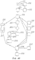
- This embodiment includes a power switch 201, a power switch state detector 202, an interruption controller 203, and a power off detection program 204.
- the present embodiment further includes a system state saving program 205, a hard disk drive 206 having a system state store file 207 as a specific area therein, a main memory 208, a CPU status store 209, an I/O status store 2010, a processing select program 2011, a processing determination program 2012, a system initialisation program 2013, a power off program 2014, a power supply unit 2015, and an electric power switch 2016 capable of turning off the power supply unit using software.
- a processing start program 2017, a system restoring program 2018, and a continuation processing program 2019 are also included.
- the power switch state detector 202 detects this and issues to the interruption controller 203 a signal for requesting an interruption in accordance with the cut off of the power. Upon receiving that signal, the interruption controller 203 causes an interruption indicating cut off of the power under. In response to the interruption, the power off detection program 204 and then the system saving program 205 are activated.
- the system saving program 205 supplies the contents of the main memory 208, the CPU status store 209 and the I/O status store 2010, in the form of one file, to the hard disk drive 206 as an external store.
- This file is the system state store file 207.
- the processing select program 2011 is activated.
- the main memory 208, the CPU status store 209 and the I/O status store 2010 are as explained in relation to the system state saving means 12. Also, the considerations in handling the file are as discussed with reference to the second embodiment of the system state saving means 12.
- the processing select program 2011 gives the user a display of the choices in the type of processing which can be executed after saving of the system state, and then waits for an instruction from the user.
- the following two choices of types of processing are provided:
- the processing determination program 2012 activates the system initialisation program 2013 or the power off program 2014.
- the system initialisation program 2013 initialises the system.
- the control is advanced to the initialisation routine prepared beforehand.
- the power off program 2014 operates the electric power switch 2016 to disconnect the power supply unit 2015, so that the supply of power to the system is cut off, as with the foregoing embodiment.
- the processing start program 2017 is activated with a command from the operating system, which in turn activates the system restoring program 2018.
- the system restoring program 2018 reads the system state, which has been saved by the system saving program 205, out of the system state store file 207 within the hard disk drive 206, thereby restoring the system state including the contents of the main memory 208, the CPU status store 209, the I/O status store 2010 etc. to its condition at the point where the power switch was last turned off.
- the considerations in restoring the contents of the main memory 208, the CPU status store 209, the I/O status store 2010 etc. are as set forth in connection with the second embodiment of the system state restoring means 15. Also, the considerations in the case when a plurality of system state store files are included are as explained in relation to the second embodiment of the system state restoring means 15.
- the external store is not limited to hard disk drives and floppy disk drives, and may include IC cards, compact disk drives, tapes, etc.
- the system state to be saved can be determined in dependence on the need for reducing the information stored.
- the present invention can provide an inexpensive and reliable means of realising continuity for a computer, so that it is possible to fully take advantage of the portable nature of small sized, battery driven computers which are likely to become more commonly used in the future.
- the invention makes it possible to improve the performance and convenience of such computers.
Abstract
Description
- The present invention relates to apparatus and a method for providing continuity of operation in a system.
- Continuity of personal computers is desirable such that when a power supply for the personal computer is turned off and then is subsequently turned on again, the system is restored to the state established immediately before the power supply was previously turned off for permitting processing being executed at the time when the power supply was turned off to continue.
- The advent of small sized, battery driven computers has resulted in portable computers which can be used irrespective of place and time, for example, while waiting for trains or aeroplanes, in free time before the start of meetings, etc. However, it is often difficult to complete all the procedures for the required processing in such a limited period of time. On these occasions, such computers would become more convenient to use, if the suspended processing could be continued later in any free moment, even after the power supply had been turned off and then on again.
- Meanwhile, if the battery voltage drops too low (LOW BATTERY) during periods of use or because a power switch is inadvertently left on by the user, processing needs to be suspended under such non-chargeable conditions and then resumed later after re-charging. In the worst case, all of the data may be lost in the course of processing due to cut off of the power supply. It is desirable, therefore, for the power supply to be turned off after the current state is saved and for the suspended processing to be continued following clearing of the LOW BATTERY condition.
- As will be seen from the above, the continuity of a computer is one of the crucial factors in improving the convenience of portable computers, in particular.
- Realisation of continuity absolutely requires the system state at the point when the power supply is turned off to be held. That is, the contents of a main memory, the setting condition of I/O ports, the state of a CPU, etc. must be held. The setting condition (status) of the I/O ports specifies in turn the condition of hardware at the time when the power supply is turned off. The condition of the hardware can be stored as information in the main memory, and so the retention of data in the main memory will be considered herein.
- With the conventional continuity techniques, the retention of data in the main memory has basically been realised by back-up of the power supply for the main memory. Specifically, power is supplied continuously to the main memory, comprising an SRAM, even after turn off of the power supply in order to retain the contents of the SRAM. Alternatively, if the main memory comprises a DRAM, a periodic refresh is effected even after turn off of the power supply.
- However, such continuity techniques give rise to the following problems:-
- (1) The system cost is increased as a result of the complexity of the circuit configuration and the specialised design of the devices employed.
- (2) Data cannot be preserved in the long term using only battery cells.
- Thus, the resulting system is expensive and does not satisfactorily accomplish continuity.
- The present invention seeks to solve the problems mentioned above, and to provide a continuity method which is inexpensive and reliable, as well as a more universal continuity system.
- According to one aspect of the present invention, there is provided an apparatus for providing continuity of operation in a system which exhibits a system condition and which performs a process, the system including a CPU having a status, a main memory for storing data and a power supply for supplying power to said system, said apparatus for providing continuity comprising:
save process start detecting means for detecting a demand to begin a save process and producing a demand signal in response thereto; characterised by further comprising;
non-volatile memory means for storing data representing the condition of said system;
system state saving means coupled to said save process start detecting means for receiving said demand signal, and coupled to said CPU and said main memory for receiving a CPU status corresponding to the status of said CPU at the time of said demand and the data in said memory at the time of said demand, the CPU status and data representing a condition of said system at an occurrence of said demand, and being further coupled to said non-volatile memory means for storing said system condition in said non-volatile memory means in response to said demand signal to the extent necessary to restore said system to enable said apparatus to perform said process and to continue said process at one of the same, next or prior step; and
post-save processing means coupled to said system state saving means for performing processing after said system state saving means has completely output said system condition to said non-volatile memory means. - As described in detail below, the apparatus can achieve not only continuity relative to the state established when a power supply was last turned off but also continuity by restoring the system to the state it was in at a yet earlier time.
- Thus, the present invention allows the system to operate in a continuous manner by recording the system state, at the time of turning off the power supply or at a time instructed by the user, into the non-volatile memory means and then restoring the recorded earlier state upon turning on the power supply or upon an instruction from the user.
- Thus, the processing occurring immediately before turn off of the power supply may be executed continuously.
- According to another aspect of the present invention, there is provided a method for providing continuity of operation in a system which exhibits a system condition and which performs a process, the system including a CPU having a status, a main memory for storing data, a non-volatile memory and a power supply for supplying power to said system, said CPU status and main memory data representing said system condition, said method comprising the steps of:
detecting a demand for saving said system condition and providing a demand signal;
storing said system condition to said non-volatile memory in response to said demand signal to the extent necessary to restore said process and to continue said process at one of the same, next or prior step; and
performing processing after said system condition has been completely stored to said non-volatile memory. - The present invention will be described further, by way of example, with reference to the accompanying drawings, in which:-
- Figure 1 is a block diagram illustrating the basic structure of a computer according to the present invention;
- Figure 2 is a block diagram illustrating a first embodiment of save process start detecting means of the computer;
- Figure 3 is a block diagram illustrating a second embodiment of save process start detecting means of the computer;
- Figure 4 is a block diagram illustrating a third embodiment of save process start detecting means of the computer;
- Figure 5 is a block diagram illustrating a fourth embodiment of save process start detecting means of the computer;
- Figure 6 is a diagram for explaining the operation of a save start command detection processing program shown in Figure 5;
- Figure 7 is a block diagram illustrating a first embodiment of a system state saving means of the computer;
- Figure 8 is a block diagram illustrating a second embodiment of system state saving means of the computer;
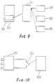
- Figure 9 is a block diagram illustrating a third embodiment of system state saving means of the computer;
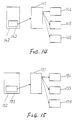
- Figure 10 is a block diagram illustrating a first embodiment of post save processing means of the computer;
- Figure 11 is a block diagram illustrating a second embodiment of post save processing means of the computer;
- Figure 12 is a block diagram illustrating a first embodiment of restore process starting means of the computer;
- Figure 13 is a block diagram illustrating a second embodiment of restore process starting means of the computer;
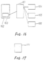
- Figure 14 is a block diagram illustrating a first embodiment of system state restoring means of the computer;
- Figure 15 is a block diagram illustrating a second embodiment of system state restoring means of the computer;
- Figure 16 is a block diagram illustrating a third embodiment of system state restoring means of the computer;
- Figure 17 is a block diagram illustrating a first embodiment of post restoration processing means of the computer;
- Figure 18 is a block diagram illustrating a second embodiment of post restoration processing means of the computer;
- Figure 19 is a block diagram illustrating in greater detail one embodiment of computer according to the present invention; and
- Figure 20 is a block diagram illustrating in greater detail another embodiment of computer according to the present invention.
- Referring initially to Figure 1, a computer according to the present invention comprises generally save process start detecting means 11, which manage and determine the timing at which the system state is to be saved. The save process is triggered by one of the following: turning off a power switch, the occurrence of a LOW BATTERY condition, or an instruction from the user, etc.
- When a decision to save is made by the save process start detecting means 11, system state saving means 12 are arranged to supply data relating to the system state to an external store that will not lose the data even if the system power is cut off.
- Post save processing means 13 then perform any processing required after the system state has been saved, for example, turning off the power supply, continued processing, initialisation, etc. Usually, the post save processing means 13 initiate turn off of the power supply.
- Subsequently, restore process starting means 14 are activated, after raising the system or upon an instruction from the user, in order to activate system state restoring means 15.
- The system state restoring means 15 read out the data relating to the earlier system state stored in the external store and sets such data in the system for restoring the previous state.
- Post restoration processing means 16 finally restart the previously interrupted process in the restored system state. As an alternative, however, it is possible for a user to interrupt the process altogether.
- Since each of the means employed in the present invention can be implemented in various ways, preferred embodiments of these means will be described first, following which typical configurations for the overall computer will be described by way of example.
- A first embodiment of the save process start detecting means 11 is shown in Figure 2, and comprises a
power switch 21, a powerswitch state detector 22, aninterruption controller 23, and a power offdetection processing program 24. - When the
power switch 21 is turned off by the user, the powerswitch state detector 22 detects the turn off of thepower switch 21 and issues to the interruption controller 23 a signal for requesting an interruption in accordance with the cut off of the power. Upon receiving that signal, theinterruption controller 23 causes an interruption indicating cut off of the power. The power offdetection processing program 24 is responsive to the interruption to detect turn off of thepower switch 21 in software terms and carries out the necessary process steps to activate the system state saving means 12 (described later). - A second embodiment of the save process start detecting
means 11 shown in Figure 3 comprises apower switch 31, aswitch state port 32, asystem timer 33, aninterruption controller 34, atimer routine 35, and a power offdetection processing program 36. - When the
power switch 31 is turned off by the user, theswitch state port 32, which is connected to thepower switch 31 and which is capable of reading the state of the power switch using a program, indicates turn off of thepower switch 31. Further, thesystem timer 33 sends an interruption request signal to theinterruption controller 34 at certain intervals, whereupon theinterruption controller 34 causes a timer interruption. In response to the interruption request, thetimer routine 35 is activated first to carry out the necessary processing such as up-dating of a counter and then to call the power offdetection processing program 36. The power offdetection processing program 36 reads theswitch state port 32 and activates the system state saving means 12 (described later) if thepower switch 31 is turned off, but returns the control back to thetimer routine 35 to terminate the timer interruption if thepower switch 31 is turned on. - While the first embodiment of the save process start detecting
means 11 is activated in response to the interruption caused upon cut off of the power, the second embodiment of the save process start detectingmeans 11 detects cut off of the power only at certain intervals during the timer interruption. - A third embodiment of the save process start detecting
means 11 will now be described with reference to Figure 4. This embodiment comprises apower switch 41, aswitch state port 42, akeyboard 43, a keyboarddata receiving unit 44, aninterruption controller 45, akeyboard interruption routine 46, a keyboarddata reading routine 47, a power offdetection processing program 48, and akeyboard data buffer 49. - In this embodiment, when the
power switch 41 is turned off by the user, theswitch state port 42, connected to thepower switch 41 and capable of reading the on/off state of the power switch using a program, indicates turn off of thepower switch 41. Further, when any key on thekeyboard 43 is depressed, the keyboarddata receiving unit 44 receives data from thekeyboard 43 indicating that that key is depressed and sends a keyboard data receiving interruption request signal to theinterruption controller 45. Theinterruption controller 45 causes a keyboard input interruption to activate thekeyboard interruption routine 46, so that the keyboard data is read out of the keyboarddata receiving unit 44 and loaded into thekeyboard data buffer 49. The keyboard data loaded into thekeyboard data buffer 49 is read out by the keyboard data reading routine 47 upon a request from a user program. The keyboard data reading routine 47 reads out the keyboard data and supplies it to the user program when keyboard data is present in thekeyboard data buffer 49, but informs the user program of the absence of a key input, or waits until there is a key input and the keyboard data is entered into thekeyboard data buffer 49, if thekeyboard data buffer 49 is vacant. The decision whether to return the null state or wait for entry of the keyboard data is determined by the function of the keyboard data reading routine 47 or by the instruction from the user program. After reading the keyboard data, or immediately before indicating to the user program that thekeyboard data buffer 49 is vacant, or during the wait for the next keyboard data to be loaded into thekeyboard data buffer 49, the keyboard data reading routine 47 calls the power offdetection processing program 48, which reads the powerswitch state port 42 and which then activates system state saving means 12 (described later) if thepower switch 41 is turned off. - While the second embodiment of the save process start detecting
means 11 detects cut off of the power in association with the timer interruption, the third embodiment of the save process start detectingmeans 11 features the detection of cut off of the power in association with the keyboard data reading program called by the user program most frequently. - A fourth embodiment of the save process start detecting
means 11, which is shown in Figure 5, comprises akeyboard 51, a keyboarddata receiving unit 52, aninterruption controller 53, akeyboard interruption routine 54, a save start commanddetection processing program 55, and akeyboard data buffer 56. - In this embodiment, when any key on the
keyboard 51 is depressed, the keyboard data indicating that that key is depressed is transmitted by thekeyboard 51 to the keyboarddata receiving unit 52, which in turn sends a keyboard data receiving interruption request signal to theinterruption controller 53. Theinterruption controller 53 activates thekeyboard interruption routine 54, so that the keyboard data is read out of the keyboarddata receiving unit 52 and loaded into thekeyboard data buffer 56, following which the keyboard interruption routine calls the save start commanddetection processing program 55. The save start commanddetection processing program 55 monitors the contents of the keyboard buffer or other data concerning the keyboard, for example concerning keyboard status, and calls the system state saving means 12 (described later) when a specified state arises. - The save start command
detection processing program 55 detects the specified state in the following manner: with reference to Figure 6, akeyboard status byte 61 includes afirst bit 62 serving as a shift key status bit, and asecond bit 63 serving as a control key status bit. - When during the
keyboard interruption routine 54, a character such as "A", for example, is depressed on the keyboard and received as input data, the received character data is loaded into akeyboard buffer 64 and, as the final input character, its location within thekeyboard buffer 64 is indicated by abuffer top pointer 65. If the next received data indicates a shift key being depressed (turned on), this data is not loaded into thekeyboard buffer 64, and the shiftkey status bit 62 as the first bit of thekeyboard status byte 61 is set to 1. Upon receiving the data indicating that the shift key has been released, the shiftkey status bit 62 is set to 0. Thus, the shiftkey status bit 62 takes 1 while the shift key is being depressed, but 0 when it is released. Likewise, the state of a control key is indicated by the controlkey status bit 63. Assuming that the instruction provided from the user to start the save processing is indicated by the fact that "the shift key and the control key are depressed simultaneously and the character "A" is further depressed", the save start commanddetection processing program 55 checks firstly whether the shiftkey status bit 62 and the controlkey status bit 63 are both set to 1 (turned on), and secondly whether the data within thekeyboard buffer 64 pointed by thebuffer top pointer 65 is "A". If the above three conditions are all satisfied, the system state saving means 12 (described later) is called. - As will be apparent from the above description, while the first to third embodiments of the save process start detecting
means 11 detect turn off of the power switch, the fourth embodiment detects an instruction input by the user from the keyboard. - In a case where the first to third embodiments of the save process start detecting
means 11 are modified by replacing the power switches 21, 31 and 41 with system voltage detection command switches, which detect electrically a decrease in voltage when the system voltage drops below a certain reference level and which operates similarly to the power switches 21, 31 and 41, the system state saving means 12 (described later) can still be activated in the same manner. The system voltage detection command switches in this instance may have a structure which takes into consideration characteristics of battery cells, the system state, time dependent variations in the decrease of the system voltage and other factors, such switches having the object of detecting a state when the charge capacity in the battery drive system has been lowered, before shut down of the system. - Referring now to the system state saving means 12, information relating to the system state, including the contents of a main memory, I/O status concerning the setting of I/O ports and hence the condition of devices in the system, the CPU state, etc., must be saved. The I/O status in terms of the setting manner and values of the I/O ports, and hence the condition of the devices, must be explicitly stated. In terms of information, however, the I/O status can be handled in a like manner to the information representing the state of the main memory and the CPU. Various means for outputting such information into an external store will now be described.
- A first embodiment of the system state saving means 12 is shown in Figure 7 and comprises a
system saving program 71, ahard disk drive 72 having a systemstate store region 73, amain memory 74, aCPU status store 75, and an I/O status store 76. - When the
system saving program 71 is activated, the contents of themain memory 74, theCPU status store 75 and the I/O status store 76 are transferred into the systemstate store region 73 within thehard disk drive 72 as an external store. After completion of this outputting task, the control initiative is transferred to post save processing means 13 (described later). - The contents of the
main memory 74 are basically only required to give information sufficient for realising system continuity. In general, the memory information that does not concern the continuity process itself needs to be saved in the state established prior to activation of the save process start detectingmeans 11. - The
CPU status store 75 gives information with which the system state restoring means 15 (described later) can restore the CPU state, existing at the time of the last or yet earlier turn off of the power switch or at the time instructed by the user, when the power switch is next turned on or when the user next provides an instruction. Generally, the CPU status is stored in a stack of themain memory 74, and hence is saved at the same time as the contents of themain memory 74. The information in a special register etc. within the CPU is saved separately. - The I/
O status store 76 gives information about I/O ports and the devices in the computer, which information is capable of setting the I/O ports and the devices and then restoring the I/O ports and the devices, to their state at the point immediately before activation of the aforesaid save process start detectingmeans 11, when the power switch is next turned on or when the system state is restored upon an instruction from the user. Those parts among the I/O information which remain unchanged irrespective of turn on/off of the power switch are not required to be saved. - The system
state store region 73 within thehard disk drive 72 has capacity reserved at the time of logical formatting, which is sufficient only to store the additional information necessary for completely saving the contents of themain memory 74, theCPU status store 75 and the I/O status store 76 under control. Hence, theregion 73 is separate from the region for storing DOS as well as the programs and data utilized under DOS. Thus, the systemstate store region 73 is fixedly maintaining within thehard disk drive 72 for being read by system state restoring means 15 (described later) for restoring the system state. - A second embodiment of the system state saving means 12 shown in Figure 8 comprises a
system saving program 81, ahard disk drive 82, a systemstate store file 83 residing in thehard disk drive 82, amain memory 84, aCPU status store 85, and an I/O status store 86. - In the embodiment shown in Figure 8, when the
system saving program 81 is activated, the contents of themain memory 84, theCPU status store 85 and the I/O status store 86 are transferred, in the form of one file, to thehard disk drive 82 as an external store. This file is the systemstate store file 83. While themain memory 84, theCPU status store 85 and the I/O status store 86 are the same as those described in connection with the first embodiment of the system state saving means 12, the present embodiment of the system state saving means features the systemstate store file 83 instead of the aforesaid systemstate store region 73 to store the relevant information. - Storing the system state in the form of a file can increase the number of states logically stored. This makes it possible to restore the system not only to the state existing at the time when the power switch was last turned off or at the time instructed by the user, but also to a state existing at the time of a yet earlier turn off of the power switch or at any time instructed by the user. Handling in the form of a file also readily permits the deletion or correction of the information stored. In the case of restoring the system to the state existing at a point earlier than the last turn off of the power switch, however, it is required for the system state restoring means 15 (described later) to execute the processing without leaving any contradictions, because of the probability of changes in the contents of the external store.
- A third embodiment of the system state saving means 12 will now be described with reference to Figure 9. This embodiment comprises a
system saving program 91, afloppy diskette 92, a systemstate store region 93 as a specific area in thefloppy diskette 92, amain memory 94, aCPU status store 95, and an I/O status store 96. - In this embodiment, the
hard disk drive 72 in the first embodiment of the system state saving means 12 is replaced by thefloppy diskette 92. Information such as the contents of themain memory 94, theCPU status store 95 and the I/O status store 96 is saved in a like manner as in the aforesaid first embodiment. - While the
hard disk drive 72 is fixed to the computer body, thefloppy diskette 92 is not fixed to the computer body and can be replaced as a recording medium. According to this embodiment, although the systemstate store region 93 is fixed in one floppy diskette, multiple system states can be recorded and retained using a plurality of floppy diskettes. In this respect, similar considerations as in the second embodiment of the system state saving means apply. - Respective embodiments of the post save processing means 13 will now be described with reference to Figures 10 and 11.
- The embodiment shown in Figure 10 comprises a
power supply unit 101, anelectric power switch 102 and an a power offprogram 103. Thepower supply unit 101 supplies power to the system. Theelectrical power switch 102 is connected to thepower supply unit 101 and is capable of disconnecting thepower supply unit 101 using software. When the power offprogram 103 initiates turning off of theelectric power switch 102, thepower supply unit 101 is disconnected and the supply of power to the system is cut off. Thus, this embodiment of themeans 13 permits the power supplied to the system to be cut off by means of software. - The embodiment of the post save processing means 13 shown in Figure 11 comprises a processing
select program 111, aprocessing determination program 112, acontinuation program 113, asystem initialisation program 114, a power offprogram 115, apower supply unit 116, and anelectric power switch 117. - This embodiment represents post save processing means which enable the type of processing to be selected upon an instruction from the user after saving the system state into the external store. In this embodiment, three choices as to the type of processing to be selected are provided. The processing
select program 111 gives the user a display of the types of processing, which may be executed after saving of the system state, and prompts the user to select any one of the choices for instructing which type of processing is to be executed. If the instruction from the user is appropriate, theprocessing determination program 112 executes the processing program selected. In this embodiment, the following three choices of types of processing are offered: - (1) continue the same processing after saving;
- (2) initialise the system and raise it from the beginning; and
- (3) cut off the power.
- Depending on which of the three choices is selected, the
continuation program 113, thesystem initialisation program 114 and the power offprogram 115 are executed, respectively. - The
continuation program 113 allows the same processing as was being executed before activation of the save process start detectingmeans 11 to be continued. In this case, it is necessary to eliminate the event which caused the save process start detectingmeans 11 to be activated, or to prevent the save process start detecting means 11 from being operated again immediately. - The
system initialisation program 114 initialises the system. In practice, the control initiative is advanced to an initialisation routine prepared beforehand. - The power off
program 115 cuts off the power for the system in a like manner to the aforesaid post save processing means 13. - The restore process starting means 14 serves to activate the system state restoring means 15 (described later) upon turning on the power for the system or upon an instruction from the user.
- A first embodiment of the restore process starting means 14 shown in Figure 12 comprises a power on
processing program 121, aboot strap loader 122, and a processstart determination program 123. - When the system power is turned on, the power on
processing program 121 starts operating to perform a basic check of the system, confirm and fixedly define the configuration, as well as initialise the I/O ports and the devices, such as RAMS, making up the system. Messages or the like are delivered, as required, to report the system state. Theboot strap loader 122 is activated to load an operating system. After loading, the control initiative is usually transferred to the loaded operating system or to the loader contained therein for raising the operating system. In the present instance, however, the control initiative is advanced to the process startdetermination program 123 to confirm whether the processing can be continued, the process startdetermination program 123 checking whether the system state has been saved by the system state saving means 12. If so, the system state restoring means 15 (described later) are activated after receiving an instruction from the user for confirmation, or directly. The system state restoring means 15 (described later) can be activated either after waiting for confirmation by the user or without conditions. In the former case, the user determines whether to execute the processing continuously, whereas in the latter case the processing is continuous at all times. - Figure 15 shows a second embodiment of the restore process starting means 14. The second embodiment comprises a
processing start program 131 which is provided as one of the commands for DOS and which runs the system state restoring means 15 (described later) if the system state has been saved by the system state saving means 12. If the system state has not been saved, theprocessing start program 131 issues a message or the like to inform the user that the system state cannot be restored. - The system state restoring means 15 will now be described, a first embodiment of these means being shown in Figure 14. The first embodiment of the system state restoring means comprises a
system restoring program 141, ahard disk drive 142 having a systemstate store region 143 as a specific area therein, amain memory 144, aCPU status store 145, and an I/O status store 146. - This embodiment of the system state restoring means 15 co-operates with the first embodiment of the system state saving means 12 in tandem. When the
system restoring program 141 is activated, the system restoring program reads the system state, which has been saved by the system state saving means 12, out of the systemstate store region 143 within thehard disk drive 142, thereby restoring the system state including the contents of themain memory 144, theCPU status store 145 and the I/O status store 146 to the preceding condition. The CPU status is completely restored to the original state in the final step of the post restoration processing means 16 (described later). Also, the I/O status is mostly restored by themeans 15, but may be changed until the final step of the post restoration processing means 16 (described later), such changes being co-ordinated by the post restoration processing means 16 to restore the I/O status completely to the previous condition. - A second embodiment of the system state restoring means 15 shown in Figure 15 comprises a
system restoring program 151, ahard disk drive 152, a systemstate store file 153 constituting a file in thehard disk drive 152, amain memory 154, aCPU status store 155, and an I/O status store 156. - This embodiment of the system state restoring means co-operates with the second embodiment of the system state saving means 12 in tandem. When the
system restoring program 151 is activated, thesystem restoring program 151 reads the system state, which has been saved by the system state saving means 12, out of the systemstate store file 153 within thehard disk drive 152, thereby restoring the system state including the contents of themain memory 154, theCPU status store 155 and the I/O status store 156 to the previous condition. The restoring method is the same as that which takes place in the aforesaid first embodiment of the system state restoring means. As stated in connection with the second embodiment of the system state saving means 12, there are a plurality of system state store files in some cases. In such cases, it is necessary to adapt thesystem restoring program 151 either for restoring the system state that was saved the last time, or for displaying the list of files to the user to prompt selection of any one list. - A third embodiment of the system state restoring means 15 is shown in Figure 16 and comprises a
system restoring program 161, afloppy diskette 162, a systemstate store region 163 constituting a specific area in thefloppy diskette 162, amain memory 164, aCPU status store 165 and an I/O status store 166. - This embodiment of the system state restoring means co-operates with the third embodiment of the system state saving means 12 in tandem. When the
system restoring program 161 is activated, thesystem restoring program 161 reads the system state, which has been saved by the system state saving means 12, out of the systemstate store region 163 within thefloppy diskette 162, thereby restoring the system state including the contents of themain memory 164, theCPU status store 165 and the I/O status store 166 to the previous condition. The restoring method is the same as that which takes place in the first embodiment of the system state restoring means 15. - Two embodiments of the post restoration processing means 16 will now be described with reference to Figures 17 and 18.
- The first embodiment shown in Figure 17 comprises a
continuation processing program 171. After the system state has been restored to the previous condition by the system state restoring means 15, the system control is advanced to thecontinuation processing program 171. Thecontinuation processing program 171 co-ordinates any changes in the system state restored by the aforesaid system state restoring means required to bring it into the final state allowing continuation processing, and then advances the system control to the point immediately following that at which the save process start detectingmeans 11 was operated. At this time, the system is already restored to the previous state, so the program which was previously being run is now finally run in a continued manner. - The second embodiment of the post restoration processing means shown in Figure 18 comprises a processing
select program 181, aprocessing determination program 182, acontinuation processing program 183, and acontinuation break program 184. - This embodiment allows the user to instruct which type of processing is to be executed, after the restoration of the system state by the aforesaid system state restoring means 15. In this embodiment, there are provided two choices as to the type of processing to be selected. The processing
select program 181 gives the user a display of the types of processing executable after restoration of the system state, and prompts the user to select one of the choices for instructing which type of processing is to be executed. If the instruction is appropriate, theprocessing determination program 182 executes the processing program selected. In this embodiment, the following types of processing are offered: - (1) restore the system to the previous state for realising continuation of the processing; and
- (2) break continuation of the processing and then return to the command mode of DOS.
- Depending on which of these two choices is selected, the
continuation processing program 183 and thecontinuation break program 184 are executed, respectively. - The
continuation processing program 183 is the same as the aforesaidcontinuation processing program 171 in the manner in which the continuation of the processing is realised. Thecontinuation break program 184 returns the processing to the usual command mode of DOS. Accordingly, continuation of the processing is suspended. - A typical computer incorporating the above individual means together will be explained below with reference to Figure 19.
- The computer comprises a
power switch 191, aswitch state port 192, asystem timer 193, aninterruption controller 194, atimer routine 195, and a power offdetection processing program 196. The computer further comprises asystem saving program 197, ahard disk drive 198, having therein a systemstate store region 199, amain memory 1910, aCPU status store 1911, an I/O status store 1912, andpower supply unit 1913 having anelectric power switch 1914 capable of turning off thepower supply unit 1913 by means of software. A power offprogram 1915 controls theswitch 1914. A power on processing program 1916, aboot strap loader 1917, aprocessing start program 1918, asystem restoring program 1919 and acontinuation processing program 1920 are also provided. - The above configuration combines the following embodiments of each of the basic means:
- (1) The save process start detecting
means 11 shown in Figure 3; - (2) The system state saving means 12 shown in Figure 7;
- (3) The post save processing means 13 shown in Figure 10;
- (4) The restore process starting means 14 shown in Figure 12;
- (5) The system state restoring means 15 shown in Figure 14; and
- (6) The post restoration processing means 16 shown in Figure 17.
- Operation of this embodiment of the computer will now be described.
- When the
power switch 191 is turned off by the user, theswitch state port 192, connected to thepower switch 191 and capable of reading the state of the power switch using a program, indicates the turn off of thepower switch 191. Further, thesystem timer 193 sends an interruption request signal to theinterruption controller 194 at certain intervals, so that theinterruption controller 194 causes a timer interruption. In response to the interruption request, thetimer routine 195 is activated to carry out the necessary processing such as up-dating of a counter and then to call the power offdetection processing program 196. The power offdetection processing program 196 reads theswitch state port 192, when it is allowed to detect the state of the power switch and continue the processing, and activates thesystem saving program 197 if thepower switch 191 is turned off, returning the control back to thetimer routine 195 to terminate the timer interruption processing if thepower switch 191 is turned on. - The
system saving program 197 supplies the contents of themain memory 1910, theCPU status store 1911 and the I/O status store 1912 into the systemstate store region 199 within thehard disk drive 198 as an external store. After completion of that task, the power offprogram 1915 is activated. Themain memory 1910, theCPU status store 1911, the I/O status store 1912 etc. are as explained above in relation to the first embodiment of the system state saving means 12. - The
power supply unit 1913 supplies power to the system. Theelectrical power switch 1914 is connected to thepower supply unit 1913 and is capable of disconnecting thepower supply unit 1913 by means of software. When the power offprogram 1915 turns off theelectric power switch 1914, thepower supply unit 1913 is disconnected and the supply of power to the system is cut off. - Next, when the system power is turned on, the power on processing program 1916 starts operating to perform a basic check of the system, confirm and fixedly define the configuration, as well as initialise the I/O ports and the devices, such as RAMS, making up the system. The
boot strap loader 197 is then activated to load an operating system (DOS). Subsequently, the process startdetermination program 1918 is activated to check whether the processing can be continued. If so, the control is advanced to thesystem restoring program 1919. - The
system restoring program 1919 reads the system state, which has been saved by thesystem saving programe 197, out of the systemstate store region 199 within thehard disk drive 198, thereby restoring the system including the contents of themain memory 1910, theCPU status store 1911, the I/O status store 1912, etc. to the state at the point when the power switch was last turned off. The various considerations in restoring the contents of themain memory 1910, theCPU status store 1911, the I/O status store 1912, etc. are as set forth in connection with the system state restoring means 15. - In order for the
system restoring program 1919 to restore the system state completely by returning the control to the point under the command executed when the power was last cut off, i.e. immediately after interruption of thetimer routine 195, without any contradications, the final state is co-ordinated by thecontinuation processing program 1920. - In this way, continuation of the processing with continuous execution can be achieved whereas otherwise the processing would be suspended mid-way by the cut off of the power.
- Another embodiment of computer according to the present invention will be described with reference to Figure 20.
- This embodiment includes a
power switch 201, a powerswitch state detector 202, aninterruption controller 203, and a power offdetection program 204. The present embodiment further includes a systemstate saving program 205, ahard disk drive 206 having a systemstate store file 207 as a specific area therein, amain memory 208, aCPU status store 209, an I/O status store 2010, a processingselect program 2011, aprocessing determination program 2012, asystem initialisation program 2013, a power offprogram 2014, apower supply unit 2015, and anelectric power switch 2016 capable of turning off the power supply unit using software. Aprocessing start program 2017, asystem restoring program 2018, and acontinuation processing program 2019 are also included. - The above configuration combines the following embodiments of each of the basic means:-
- (1) The save process start detecting
means 11 shown in Figure 2; - (2) The save start saving
means 12 shown in Figure 8; - (3) The post save processing means 13 shown in Figure 11;
- (4) The restore process starting means 14 shown in Figure 13;
- (5) The system state restoring means 15 shown in Figure 15; and
- (6) The post restoration processing means 16 shown in Figure 17.
- Operation of this embodiment will now be described.
- When the
power switch 201 is turned off, the powerswitch state detector 202 detects this and issues to the interruption controller 203 a signal for requesting an interruption in accordance with the cut off of the power. Upon receiving that signal, theinterruption controller 203 causes an interruption indicating cut off of the power under. In response to the interruption, the power offdetection program 204 and then thesystem saving program 205 are activated. - The
system saving program 205 supplies the contents of themain memory 208, theCPU status store 209 and the I/O status store 2010, in the form of one file, to thehard disk drive 206 as an external store. This file is the systemstate store file 207. After completion of that task, the processingselect program 2011 is activated. Themain memory 208, theCPU status store 209 and the I/O status store 2010 are as explained in relation to the system state saving means 12. Also, the considerations in handling the file are as discussed with reference to the second embodiment of the system state saving means 12. - The processing
select program 2011 gives the user a display of the choices in the type of processing which can be executed after saving of the system state, and then waits for an instruction from the user. In this embodiment, the following two choices of types of processing are provided: - (1) initialise the system and raise it from the beginning; and
- (2) cut off the power.
- Depending on which of the two choices is selected, the
processing determination program 2012 activates thesystem initialisation program 2013 or the power offprogram 2014. Thesystem initialisation program 2013 initialises the system. In practice, the control is advanced to the initialisation routine prepared beforehand. The power offprogram 2014 operates theelectric power switch 2016 to disconnect thepower supply unit 2015, so that the supply of power to the system is cut off, as with the foregoing embodiment. - Subsequently, when the system power is turned on to raise the system, the
processing start program 2017 is activated with a command from the operating system, which in turn activates thesystem restoring program 2018. - The
system restoring program 2018 reads the system state, which has been saved by thesystem saving program 205, out of the systemstate store file 207 within thehard disk drive 206, thereby restoring the system state including the contents of themain memory 208, theCPU status store 209, the I/O status store 2010 etc. to its condition at the point where the power switch was last turned off. The considerations in restoring the contents of themain memory 208, theCPU status store 209, the I/O status store 2010 etc. are as set forth in connection with the second embodiment of the system state restoring means 15. Also, the considerations in the case when a plurality of system state store files are included are as explained in relation to the second embodiment of the system state restoring means 15. - In order for the
system restoring program 2018 to restore the system state completely by returning the control to the point following the command executed immediately before the power was last cut off, i.e. immediately after interruption of the power offdetection program 204, without any contradictions, the final state is co-ordinated by thecontinuation processing program 2019. - While various embodiments of the present invention have been described above, it will be understood taking into account the practical implementation of the respective means and combinations thereof that many other embodiments are possible in addition to the illustrated ones. For example, the external store is not limited to hard disk drives and floppy disk drives, and may include IC cards, compact disk drives, tapes, etc. The system state to be saved can be determined in dependence on the need for reducing the information stored.
- In any event, however, the present invention can provide an inexpensive and reliable means of realising continuity for a computer, so that it is possible to fully take advantage of the portable nature of small sized, battery driven computers which are likely to become more commonly used in the future. The invention makes it possible to improve the performance and convenience of such computers.
Claims (25)
- An apparatus for providing continuity of operation in a system which exhibits a system condition and which performs a process, the system including a CPU having a status, a main memory (84) for storing data and a power supply (101) for supplying power to said system, said apparatus for providing continuity comprising:
save process start detecting means (11) for detecting a demand to begin a save process and producing a demand signal in response thereto; characterised by further comprising;
non-volatile memory means (72) for storing data representing the condition of said system;
system state saving means (12) coupled to said save process start detecting means for receiving said demand signal, and coupled to said CPU and said main memory for receiving a CPU status corresponding to the status of said CPU at the time of said demand and the data in said memory at the time of said demand, the CPU status and data representing a condition of said system at an occurrence of said demand, and being further coupled to said non-volatile memory means for storing said system condition in said non-volatile memory means in response to said demand signal to the extent necessary to restore said system to enable said apparatus to perform said process and to continue said process at one of the same, next or prior step; and
post-save processing means (13) coupled to said system state saving means for performing processing after said system state saving means has completely output said system condition to said non-volatile memory means. - The apparatus for providing continuity of operation according to claim 1, wherein said demand to begin a save process is initiated by a user, and wherein said save process start detecting means includes user instruction input means (51) to provide a user input, said user input indicating a demand to begin a save process and wherein said save process start detecting means produces said demand signal in response to said user input indicating a demand to begin a save process.
- The apparatus for providing continuity of operation according to claim 1 or 2, wherein said non-volatile memory means includes a fixedly reserved system state store region (73), and wherein said system state saving means stores said system condition in said fixedly reserved system state store region of said non-volatile memory means.
- The apparatus for providing continuity of operation according to claim 1 or 2, wherein said non-volatile memory means includes at least one system state store file (83), and wherein said system state saving means stores said system condition in said at least one system state store file of said non-volatile memory means.
- The apparatus for providing continuity of operation according to claim 1 or 2, wherein said non-volatile memory means includes a contiguous system state store region and wherein said system state saving means stores said system condition in said contiguous system state store region of said non-volatile memory means.
- The apparatus for providing continuity of operation as claimed in any preceding claim, wherein the system further includes a plurality of input/output ports and/or devices having a status; and said system state saving means is additionally coupled to said plurality of input/output ports and/or devices for further receiving an I/O status corresponding to the status of said plurality of input/output ports and/or devices at the time of said demand, said I/O status, in addition to the CPU status and data, representing a condition of said system at an occurrence of said demand.
- The apparatus for providing continuity of operation according to any of claims 1 to 6, further comprising:
restore process start means (14) coupled to said power supply for detecting when said power supply is turned on and outputting a detection signal in response thereto;
system state restoring means (15) coupled to said restore process start means for receiving said detection signal, coupled to said non-volatile memory means for reading said system condition therefrom, and coupled to said CPU and main memory for restoring, in response to said detection signal, said CPU and main memory to the system condition stored in said non-volatile memory means, whereby said process can be continued at one of the same, next or prior process step as the process step occurring when said demand was detected by said save process start detecting means. - The apparatus for providing continuity of operation according to any of claims 1 to 6, further comprising:
restore process start means (14) coupled to said power supply for detecting when said power supply is turned on and outputting a detection signal in response thereto;
process selecting means (181) operatively coupled to said restore process start means for displaying to a user a plurality of processes which may be executed, at least one of said displayed processes being continuing the operation of said process after the system condition has been restored; and
system state restoring means (15) coupled to said non-volatile memory means for reading said system condition therefrom, and coupled to said CPU and said main memory for restoring said CPU and said main memory to the system condition stored in said non-volatile memory means at one of the same, next to prior process step as the process step occurring when said demand was detected by said process start detecting means. - The apparatus for providing continuity of operation according to any of claims 1 to 6, further comprising:
restore process start means (14) coupled to said power supply for detecting when said power supply is turned on and outputting a detection signal in response thereto;
process start determination means coupled to said restore process start means for receiving said detection signal, said process start determination means confirming, in response to said detection signal, whether processing can be continued from a system condition saved in said non-volatile memory means and outputting a confirmation if said processing can continue;
system state restoring means (15) coupled to said process start determination means, coupled to said non-volatile memory means for reading said system condition therefrom, and coupled to said CPU and main memory for restoring said CPU and main memory to the system condition stored in said non-volatile memory means in response to said confirmation from said process start determination means that processing can be continued from a system condition saved in said non-volatile memory means; and
post-restore processing means (16) coupled to said system state restoring means for determining when the CPU and main memory are restored to the system condition which existed at the time of said demand to begin a save process, and coupled to said CPU and main memory for controlling the operation of said process after the system state restoring means has restored said system condition, said post-restore processing means continuing said process at one of the same, next or prior process step as the process step occurring when said demand was detected by said save process start detecting means. - The apparatus for providing continuity of operation according to claim 7 or 8, wherein;
said system state restoring means is additionally coupled to said plurality of input/output ports and/or devices for additionally restoring, in response to said detection signal, said plurality of input/output ports and/or devices to the system condition stored in said non-volatile memory means, whereby said process can be continued at one of the same, next or prior process step as the process step occurring when said demand was detected by said save process start detecting means. - The apparatus for providing continuity of operation according to claim 9, wherein;
said system state restoring means is additionally coupled to said plurality of input/output ports and/or devices for additionally restoring said plurality of input/output ports and/or devices to the system condition stored in said non-volatile memory means in response to said confirmation from said process start determination means that processing can be continued from a system condition saved in said non-volatile memory means; and
said post-restore processing means coupled to said system state restoring means for further determining when said plurality of input/output ports and/or devices are restored to the system condition which existed at the time of said demand to begin a save process, and additionally coupled to said plurality of input/output ports and/or devices for controlling the operation of said process after the system state restoring means has restored said system condition, said post-restore processing means continuing said process at one of the same, next or prior process step as the process step occurring when said demand was detected by said save process start detecting means. - The apparatus for providing continuity of operation according to any preceding claim, wherein said save process start detecting means further includes a switch (21) having an on state and an off state, and power off detection processing means (22) for reading the power switch state indicated by said switch and producing a demand signal when said power switch is in an off state.
- The apparatus for providing continuity of operation according to any preceding claim, wherein said power supply includes a battery having a voltage, and said save process start detecting means includes a battery voltage detection processing means for detecting the voltage of the battery and producing a demand signal when said voltage falls below a predetermined value.
- The apparatus for providing continuity of operation to any preceding claim, wherein said post-save processing means is further coupled to said power supply and turns off said power supply after said system state saving means has completely stored said system condition to said non-volatile memory means.
- The apparatus for providing continuity of operation according to any preceding claim, wherein said post-save processing means further includes process selecting means (111) operatively coupled to said system state saving means for displaying to a user a plurality of processes which may be executed after said system condition has been stored in said non-volatile memory means, and process determination means for permitting selection of one of said plurality of displayed processes in accordance with an input from said user, at least one of said processes being continuing with the current process.
- The apparatus for providing continuity of operation according to any preceding claim, wherein said non-volatile memory means includes an external storage means.
- The apparatus for providing continuity of apparatus according to claim 16, wherein said external storage means includes a hard disk drive.
- A method for providing continuity of operation in a system which exhibits a system condition and which performs a process, the system including a CPU having a status, a main memory (84) for storing data, a non-volatile memory (72) and a power supply (101) for supplying power to said system, said CPU status and main memory data representing said system condition, said method comprising the steps of:
detecting a demand for saving said system condition and providing a demand signal;
storing said system condition to said non-volatile memory in response to said demand signal to the extent necessary to restore said process and to continue said process at one of the same, next or prior step; and
performing processing after said system condition has been completely stored to said non-volatile memory. - The method for providing continuity of operation according to claim 18, wherein said demand for saving said system condition is initiated by a user.
- The method for providing continuity of operation according to claim 18 or claim 19, wherein said non-volatile memory includes a fixedly reserved system state store region (73) and said system condition is stored to said fixedly reserved system state store region of said non-volatile memory.
- The method for providing continuity of operation according to claim 18 or claim 19 wherein said non-volatile memory includes a contiguous system state store region and said system condition is stored to said contiguous system state store region of said non-volatile memory.
- The method for providing continuity of operation according to claim 18 to 19, wherein said non-volatile memory includes a system state store file (83) and said system condition is stored to said system state store file of said non-volatile memory.
- The method for providing continuity of operation according to any one of claims 18 to 22, wherein the system further includes a plurality of input/output ports and/or devices having a status, and said status of said plurality of input/output ports and/or devices also represents said system condition.
- The method for providing continuity of operation according to any one of claims 18 to 23, wherein said non-volatile memory includes an external storage means.
- The method for providing continuity of operation according to claim 24, wherein said external storage includes a hard disk drive.
Applications Claiming Priority (4)
| Application Number | Priority Date | Filing Date | Title |
|---|---|---|---|
| JP63222743A JP2779813B2 (en) | 1988-09-06 | 1988-09-06 | computer |
| JP22274388 | 1988-09-06 | ||
| JP222743/88 | 1988-09-06 | ||
| EP89308923A EP0365128B1 (en) | 1988-09-06 | 1989-09-04 | Computer system and method of preserving the state of the system |
Related Parent Applications (2)
| Application Number | Title | Priority Date | Filing Date |
|---|---|---|---|
| EP89308923A Division EP0365128B1 (en) | 1988-09-06 | 1989-09-04 | Computer system and method of preserving the state of the system |
| EP89308923.5 Division | 1989-09-04 |
Publications (3)
| Publication Number | Publication Date |
|---|---|
| EP0720096A2 true EP0720096A2 (en) | 1996-07-03 |
| EP0720096A3 EP0720096A3 (en) | 2002-06-19 |
| EP0720096B1 EP0720096B1 (en) | 2005-06-15 |
Family
ID=16787210
Family Applications (2)
| Application Number | Title | Priority Date | Filing Date |
|---|---|---|---|
| EP89308923A Expired - Lifetime EP0365128B1 (en) | 1988-09-06 | 1989-09-04 | Computer system and method of preserving the state of the system |
| EP96103428A Expired - Lifetime EP0720096B1 (en) | 1988-09-06 | 1989-09-04 | Apparatus and method for providing continuity of operation in a system |
Family Applications Before (1)
| Application Number | Title | Priority Date | Filing Date |
|---|---|---|---|
| EP89308923A Expired - Lifetime EP0365128B1 (en) | 1988-09-06 | 1989-09-04 | Computer system and method of preserving the state of the system |
Country Status (5)
| Country | Link |
|---|---|
| US (4) | US5379435A (en) |
| EP (2) | EP0365128B1 (en) |
| JP (1) | JP2779813B2 (en) |
| DE (2) | DE68929536T2 (en) |
| SG (1) | SG49819A1 (en) |
Cited By (2)
| Publication number | Priority date | Publication date | Assignee | Title |
|---|---|---|---|---|
| DE19646564A1 (en) * | 1996-11-12 | 1998-05-14 | Schlafhorst & Co W | Winder for cross wound bobbins |
| GB2395302A (en) * | 2002-11-13 | 2004-05-19 | Advanced Risc Mach Ltd | State saving and restoring in data processing system using scan chain cells |
Families Citing this family (65)
| Publication number | Priority date | Publication date | Assignee | Title |
|---|---|---|---|---|
| JP2779813B2 (en) * | 1988-09-06 | 1998-07-23 | セイコーエプソン株式会社 | computer |
| JP3275261B2 (en) * | 1990-03-09 | 2002-04-15 | セイコーエプソン株式会社 | Information processing device |
| DE69125567T2 (en) * | 1990-10-18 | 1997-08-21 | Seiko Epson Corp | Information processing device for backing up and restoring data |
| JP3019934B2 (en) * | 1991-05-01 | 2000-03-15 | ソニー株式会社 | Information processing method and apparatus |
| US5652890A (en) * | 1991-05-17 | 1997-07-29 | Vantus Technologies, Inc. | Interrupt for a protected mode microprocessor which facilitates transparent entry to and exit from suspend mode |
| EP0584257B1 (en) | 1991-05-17 | 2004-08-04 | Packard Bell NEC, Inc. | Power management capability for a microprocessor having backward compatibility |
| US5551033A (en) | 1991-05-17 | 1996-08-27 | Zenith Data Systems Corporation | Apparatus for maintaining one interrupt mask register in conformity with another in a manner invisible to an executing program |
| JPH077317B2 (en) * | 1991-06-10 | 1995-01-30 | 松下電器産業株式会社 | System restart device |
| JPH07101376B2 (en) * | 1991-06-10 | 1995-11-01 | 松下電器産業株式会社 | System restart device |
| JPH077316B2 (en) * | 1991-06-10 | 1995-01-30 | 松下電器産業株式会社 | System restart device |
| EP0523652B1 (en) * | 1991-07-16 | 1999-02-03 | Canon Kabushiki Kaisha | Electronic apparatus with resume function |
| US5592675A (en) | 1992-01-08 | 1997-01-07 | Hitachi, Ltd. | Computer controlled method and system capable of preserving information representing plural work states and recovering the work states |
| JPH06250754A (en) * | 1993-02-22 | 1994-09-09 | Nec Corp | System startup time shortening method |
| JP2688164B2 (en) * | 1993-07-26 | 1997-12-08 | インターナショナル・ビジネス・マシーンズ・コーポレイション | Information processing system |
| US5809311A (en) * | 1994-07-14 | 1998-09-15 | Dell U.S.A., L.P. | System and method for providing centralized backup power in a computer system |
| US5630142A (en) * | 1994-09-07 | 1997-05-13 | International Business Machines Corporation | Multifunction power switch and feedback led for suspend systems |
| JP2921412B2 (en) * | 1994-09-30 | 1999-07-19 | 日本電気株式会社 | Data processing device |
| KR0174483B1 (en) * | 1994-12-22 | 1999-04-01 | 윤종용 | Computer system capable of recovering work by key signal input and its control method |
| US5748874A (en) * | 1995-06-05 | 1998-05-05 | Mti Technology Corporation | Reserved cylinder for SCSI device write back cache |
| EP0749063A3 (en) * | 1995-06-07 | 1999-01-13 | International Business Machines Corporation | Method and apparatus for suspend/resume operation in a computer |
| US5758174A (en) * | 1995-06-07 | 1998-05-26 | International Business Machines Corporation | Computer system having a plurality of stored system capability states from which to resume |
| US5745391A (en) * | 1995-09-13 | 1998-04-28 | Topor; Yakov | Apparatus for and method of turning on and shutting off a computing device |
| US5708819A (en) * | 1995-10-10 | 1998-01-13 | Standard Microsystems Corporation | Process and apparatus for generating power management events in a computer system |
| KR0156802B1 (en) * | 1995-11-07 | 1998-11-16 | 김광호 | Network hybernation system |
| US5928365A (en) * | 1995-11-30 | 1999-07-27 | Kabushiki Kaisha Toshiba | Computer system using software controlled power management method with respect to the main memory according to a program's main memory utilization states |
| KR0180801B1 (en) * | 1995-11-30 | 1999-05-15 | 김광호 | Control device for switching mode power supply |
| US5974552A (en) * | 1995-12-29 | 1999-10-26 | Samsung Electronics Co., Ltd. | Method and apparatus for executing a scheduled operation after wake up from power off state |
| US6678712B1 (en) | 1996-01-19 | 2004-01-13 | International Business Machines Corporation | Method and system for executing a program under one of a plurality of mutually exclusive operating environments |
| JP2988866B2 (en) * | 1996-02-29 | 1999-12-13 | 株式会社東芝 | Computer system |
| FR2750516B1 (en) * | 1996-07-01 | 1998-07-31 | Bull Cp8 | DEVICE FOR COMMUNICATING WITH A PORTABLE DATA MEDIUM |
| US5875344A (en) * | 1996-07-16 | 1999-02-23 | Compaq Computer Corporation | Using a file enabler with firmware |
| KR100278355B1 (en) * | 1996-09-30 | 2001-01-15 | 윤종용 | Computer system and control method of this computer system |
| JP3253881B2 (en) * | 1997-01-06 | 2002-02-04 | 株式会社東芝 | Computer system and hibernation control method in the system |
| US5880536A (en) * | 1997-05-14 | 1999-03-09 | Io Limited Partnership, Llp | Customer side power management system including auxiliary fuel cell for reducing potential peak load upon utilities and providing electric power for auxiliary equipment |
| US6212609B1 (en) * | 1997-06-30 | 2001-04-03 | Intel Corporation | Alternate access mechanism for saving and restoring state of read-only register |
| US6145068A (en) * | 1997-09-16 | 2000-11-07 | Phoenix Technologies Ltd. | Data transfer to a non-volatile storage medium |
| JPH11143567A (en) * | 1997-11-06 | 1999-05-28 | Fujitsu Ltd | Information protection method for network system and information processor used for the protection method |
| KR100294852B1 (en) | 1997-11-24 | 2001-07-12 | 윤종용 | Computer enabling user to switch off power without data loss, and its method |
| JPH11161385A (en) | 1997-11-28 | 1999-06-18 | Toshiba Corp | Computer system and its system state control method |
| US5943635A (en) * | 1997-12-12 | 1999-08-24 | Scenix Semiconductor Inc. | System and method for programmable brown-out detection and differentiation |
| US6092207A (en) * | 1997-12-29 | 2000-07-18 | Intel Corporation | Computer having a dual mode power supply for implementing a power saving mode |
| US6178523B1 (en) * | 1998-06-12 | 2001-01-23 | Philips Consumer Communications Lp | Battery-operated device with power failure recovery |
| US6256714B1 (en) | 1998-09-02 | 2001-07-03 | Sharp Laboratories Of America, Inc. | Computer system with efficient memory usage for managing multiple application programs |
| US6490664B1 (en) * | 1999-06-14 | 2002-12-03 | International Business Machines Corporation | Method and system for handling destage requests during shut-down in a log-structured array |
| US6601181B1 (en) | 1999-12-14 | 2003-07-29 | Gateway, Inc. | Uninterruptible power supply apparatus and method |
| US6742140B2 (en) * | 2000-12-01 | 2004-05-25 | Jason R. Caulkins | Method for using volatile memory for long-term storage |
| DE10063934A1 (en) * | 2000-12-20 | 2002-06-27 | Bosch Gmbh Robert | Monitoring and, if necessary, switching off of control units in a network of distributed control units, based on a combined fault and switching off decision making matrix that provides increased flexibility |
| US20020113777A1 (en) * | 2001-02-21 | 2002-08-22 | John Lauderdale | Exit key for computer keyboard |
| WO2002073230A2 (en) * | 2001-03-14 | 2002-09-19 | Mercury Computer Systems, Inc. | Wireless communications methods and systems for short-code and other spread spectrum waveform processing |
| KR100457558B1 (en) * | 2002-03-06 | 2004-11-18 | 엘지전자 주식회사 | Refrigerator Hard Disk Drive Controlling Method |
| EP1359507A1 (en) * | 2002-04-29 | 2003-11-05 | Hewlett-Packard Company | Data processing system and method |
| US6901298B1 (en) * | 2002-09-30 | 2005-05-31 | Rockwell Automation Technologies, Inc. | Saving and restoring controller state and context in an open operating system |
| TW591372B (en) * | 2003-05-15 | 2004-06-11 | High Tech Comp Corp | Power control method of portable electronic device, portable electronic device and electronic system |
| TW200428190A (en) * | 2003-06-03 | 2004-12-16 | Icp Electronics Inc | Safe power-off system and method thereof |
| TWI279726B (en) * | 2005-09-28 | 2007-04-21 | Lite On Technology Corp | Method and computer system for securing backup data from damage by virus and hacker program |
| US20070168591A1 (en) * | 2005-12-08 | 2007-07-19 | Inter-Tel, Inc. | System and method for validating codec software |
| JP4908983B2 (en) * | 2006-09-12 | 2012-04-04 | パナソニック株式会社 | Microcontrollers and related technologies |
| US20080244444A1 (en) * | 2007-03-30 | 2008-10-02 | Microsoft Corporation | Contextual computer workspace |
| JP2009061216A (en) * | 2007-09-10 | 2009-03-26 | Morioka Seiko Instruments Inc | Electronic shelf tag |
| US8589733B2 (en) * | 2010-08-13 | 2013-11-19 | International Business Machines Corporation | Saving operational state of open applications when unexpected shutdown events occur |
| CN102376322A (en) * | 2010-08-20 | 2012-03-14 | 环达电脑(上海)有限公司 | Portable electronic equipment control device and method |
| US9495173B2 (en) | 2011-12-19 | 2016-11-15 | Sandisk Technologies Llc | Systems and methods for managing data in a device for hibernation states |
| TWI454013B (en) * | 2012-08-01 | 2014-09-21 | Pegatron Corp | Charging method and electronic device using the same |
| CN103092315B (en) * | 2013-01-09 | 2015-11-25 | 惠州Tcl移动通信有限公司 | The mobile terminal of rear recovery application program can be restarted |
| KR20150129517A (en) * | 2014-05-12 | 2015-11-20 | 엘에스산전 주식회사 | Electronic Device with memory data backup function |
Citations (4)
| Publication number | Priority date | Publication date | Assignee | Title |
|---|---|---|---|---|
| US3959778A (en) * | 1973-09-05 | 1976-05-25 | Compagnie Honeywell Bull (Societe Anonyme) | Apparatus for transferring data from a volatile main memory to a store unit upon the occurrence of an electrical supply failure in a data processing system |
| GB1545169A (en) * | 1977-09-22 | 1979-05-02 | Burroughs Corp | Data processor system including data-save controller for protection against loss of volatile memory information during power failure |
| EP0230351A2 (en) * | 1986-01-17 | 1987-07-29 | International Business Machines Corporation | Information processing system |
| JPS6339053A (en) * | 1986-08-01 | 1988-02-19 | Nec Corp | Memory compression dump/evolution display system |
Family Cites Families (41)
| Publication number | Priority date | Publication date | Assignee | Title |
|---|---|---|---|---|
| US3757302A (en) * | 1971-11-16 | 1973-09-04 | Addressograph Multigraph | Responsive power fail detection system |
| US3801963A (en) * | 1972-09-28 | 1974-04-02 | Burroughs Corp | Method and apparatus for transferring data from a volatile data store upon the occurrence of a power failure in a computer |
| US4131942A (en) * | 1977-01-10 | 1978-12-26 | Xerox Corporation | Non-volatile storage module for a controller |
| US4307455A (en) * | 1978-02-27 | 1981-12-22 | Rockwell International Corporation | Power supply for computing means with data protected shut-down |
| JPS5682923A (en) * | 1979-12-07 | 1981-07-07 | Casio Comput Co Ltd | Automatic power source disconnection device |
| JPS5725023A (en) * | 1980-07-23 | 1982-02-09 | Canon Inc | Electronic apparatus |
| US4523295A (en) * | 1982-09-07 | 1985-06-11 | Zenith Electronics Corporation | Power loss compensation for programmable memory control system |
| JPS59133603A (en) * | 1983-01-20 | 1984-08-01 | Omron Tateisi Electronics Co | Programmable controller |
| JPS59140572A (en) * | 1983-01-31 | 1984-08-11 | Canon Inc | Electronic apparatus |
| JPS605363A (en) * | 1983-06-22 | 1985-01-11 | Sharp Corp | Confirmation system for memory contents |
| US4611289A (en) * | 1983-09-29 | 1986-09-09 | Coppola Anthony F | Computer power management system |
| JPS60132220A (en) * | 1983-12-20 | 1985-07-15 | Sanyo Electric Co Ltd | Microcomputer |
| JPS60225924A (en) * | 1984-04-25 | 1985-11-11 | Seiko Epson Corp | Information processor |
| JPS61101870A (en) * | 1984-10-25 | 1986-05-20 | Oki Electric Ind Co Ltd | Documentation device |
| JPS61127021A (en) * | 1984-11-27 | 1986-06-14 | Mitsubishi Electric Corp | Terminal equipment |
| JPS61255440A (en) * | 1985-05-08 | 1986-11-13 | Nec Corp | Program interruption control system |
| JP2530595B2 (en) * | 1985-05-17 | 1996-09-04 | キヤノン株式会社 | Information processing device |
| US4907150A (en) * | 1986-01-17 | 1990-03-06 | International Business Machines Corporation | Apparatus and method for suspending and resuming software applications on a computer |
| JPS62208151A (en) * | 1986-03-07 | 1987-09-12 | Matsushita Electric Ind Co Ltd | Information processor |
| JPS62254222A (en) * | 1986-04-28 | 1987-11-06 | Sharp Corp | Protecting device against service interruption |
| US4868832A (en) * | 1986-04-30 | 1989-09-19 | Marrington S Paul | Computer power system |
| JPS6325713A (en) * | 1986-07-18 | 1988-02-03 | Nec Corp | Control system for cut-off of power supply |
| JPS6380649A (en) * | 1986-09-24 | 1988-04-11 | Seiko Instr & Electronics Ltd | Portable information communication device |
| JPH0833838B2 (en) * | 1986-09-25 | 1996-03-29 | 株式会社東芝 | Computer system |
| JPS63184123A (en) * | 1986-09-30 | 1988-07-29 | Canon Inc | Information processor |
| JPS6380649U (en) * | 1986-11-13 | 1988-05-27 | ||
| JPH07122839B2 (en) * | 1986-11-18 | 1995-12-25 | キヤノン株式会社 | Data processing device |
| US5339446A (en) * | 1986-12-26 | 1994-08-16 | Kabushiki Kaisha Toshiba | Power supply and method for use in a computer system to confirm a save operation of the computer system and to stop a supply of power to the computer system after confirmation |
| US5012406A (en) * | 1988-04-19 | 1991-04-30 | Power Card Supply | Line of power interruption in predetermined area of internal permanent memory |
| JP2779813B2 (en) * | 1988-09-06 | 1998-07-23 | セイコーエプソン株式会社 | computer |
| US4965828A (en) * | 1989-04-05 | 1990-10-23 | Quadri Corporation | Non-volatile semiconductor memory with SCRAM hold cycle prior to SCRAM-to-E2 PROM backup transfer |
| US5163153A (en) * | 1989-06-12 | 1992-11-10 | Grid Systems Corporation | Low-power, standby mode computer |
| US5151855A (en) * | 1989-10-19 | 1992-09-29 | Saturn Corporation | Multiple microprocessor single power supply system shutdown |
| US5276890A (en) * | 1989-11-30 | 1994-01-04 | Kabushiki Kaisha Toshiba | Resume control system and method for executing resume processing while checking operation mode of CPU |
| US5317752A (en) * | 1989-12-22 | 1994-05-31 | Tandem Computers Incorporated | Fault-tolerant computer system with auto-restart after power-fall |
| US5355503A (en) * | 1990-05-31 | 1994-10-11 | National Semiconductor Corporation | Event driven scanning of data input equipment using multi-input wake-up techniques |
| US5193176A (en) * | 1990-10-17 | 1993-03-09 | Powercard Supply C.A. | Computer work saving during power interruption |
| US5355490A (en) * | 1991-06-14 | 1994-10-11 | Toshiba America Information Systems, Inc. | System and method for saving the state for advanced microprocessor operating modes |
| JPH06236284A (en) * | 1991-10-21 | 1994-08-23 | Intel Corp | Method for preservation and restoration of computer-system processing state and computer system |
| US5276865A (en) * | 1992-05-06 | 1994-01-04 | Thorpe Tracy J | Automatic computer back-up system |
| JP3680901B2 (en) * | 1997-12-11 | 2005-08-10 | 東芝機械株式会社 | Plastic mixing screw |
-
1988
- 1988-09-06 JP JP63222743A patent/JP2779813B2/en not_active Expired - Lifetime
-
1989
- 1989-09-04 EP EP89308923A patent/EP0365128B1/en not_active Expired - Lifetime
- 1989-09-04 DE DE68929536T patent/DE68929536T2/en not_active Expired - Lifetime
- 1989-09-04 DE DE68929116T patent/DE68929116T2/en not_active Expired - Lifetime
- 1989-09-04 EP EP96103428A patent/EP0720096B1/en not_active Expired - Lifetime
- 1989-09-04 SG SG1996006775A patent/SG49819A1/en unknown
-
1992
- 1992-11-17 US US07/978,296 patent/US5379435A/en not_active Expired - Lifetime
-
1994
- 1994-11-17 US US08/341,252 patent/US5530877A/en not_active Expired - Lifetime
-
1995
- 1995-06-06 US US08/470,147 patent/US5848280A/en not_active Expired - Lifetime
-
1998
- 1998-11-23 US US09/197,797 patent/US6108792A/en not_active Expired - Fee Related
Patent Citations (4)
| Publication number | Priority date | Publication date | Assignee | Title |
|---|---|---|---|---|
| US3959778A (en) * | 1973-09-05 | 1976-05-25 | Compagnie Honeywell Bull (Societe Anonyme) | Apparatus for transferring data from a volatile main memory to a store unit upon the occurrence of an electrical supply failure in a data processing system |
| GB1545169A (en) * | 1977-09-22 | 1979-05-02 | Burroughs Corp | Data processor system including data-save controller for protection against loss of volatile memory information during power failure |
| EP0230351A2 (en) * | 1986-01-17 | 1987-07-29 | International Business Machines Corporation | Information processing system |
| JPS6339053A (en) * | 1986-08-01 | 1988-02-19 | Nec Corp | Memory compression dump/evolution display system |
Cited By (5)
| Publication number | Priority date | Publication date | Assignee | Title |
|---|---|---|---|---|
| DE19646564A1 (en) * | 1996-11-12 | 1998-05-14 | Schlafhorst & Co W | Winder for cross wound bobbins |
| US6014592A (en) * | 1996-11-12 | 2000-01-11 | W. Schlafhorst Ag & Co. | Cheese-producing textile machine |
| DE19646564B4 (en) * | 1996-11-12 | 2005-07-14 | Saurer Gmbh & Co. Kg | Cheese making textile machine |
| GB2395302A (en) * | 2002-11-13 | 2004-05-19 | Advanced Risc Mach Ltd | State saving and restoring in data processing system using scan chain cells |
| GB2395302B (en) * | 2002-11-13 | 2005-12-28 | Advanced Risc Mach Ltd | Hardware driven state save/restore in a data processing system |
Also Published As
| Publication number | Publication date |
|---|---|
| DE68929536D1 (en) | 2005-07-21 |
| SG49819A1 (en) | 1998-06-15 |
| EP0365128A2 (en) | 1990-04-25 |
| EP0365128B1 (en) | 1999-12-15 |
| US5530877A (en) | 1996-06-25 |
| EP0720096A3 (en) | 2002-06-19 |
| US5848280A (en) | 1998-12-08 |
| JPH0269812A (en) | 1990-03-08 |
| US5379435A (en) | 1995-01-03 |
| EP0365128A3 (en) | 1991-07-31 |
| DE68929116D1 (en) | 2000-01-20 |
| DE68929116T2 (en) | 2000-04-13 |
| US6108792A (en) | 2000-08-22 |
| EP0720096B1 (en) | 2005-06-15 |
| DE68929536T2 (en) | 2005-11-03 |
| JP2779813B2 (en) | 1998-07-23 |
Similar Documents
| Publication | Publication Date | Title |
|---|---|---|
| EP0720096B1 (en) | Apparatus and method for providing continuity of operation in a system | |
| EP0518623B1 (en) | Apparatus and method for suspending and resuming software applications on a computer | |
| US5721932A (en) | Information processing apparatus with resume function and information processing system | |
| US4763333A (en) | Work-saving system for preventing loss in a computer due to power interruption | |
| US5117324A (en) | Ups-computer system and method for initiating computer shutdown based on remaining battery time as determined from sensed battery voltage and discharge curves | |
| EP0518622B1 (en) | Apparatus and method for suspending and resuming software on a computer | |
| EP0658843A1 (en) | Method for hibernation file creation | |
| JP3047791B2 (en) | computer | |
| US5590340A (en) | Apparatus and method for suspending and resuming software application on a computer | |
| EP0167322A2 (en) | Shadow memory system | |
| US5557739A (en) | Computer system with component removal and replacement control scheme | |
| EP0653826B1 (en) | Battery-driven electronic appliance | |
| KR19980074058A (en) | Computer with power cutoff function and power cutoff method | |
| JP3133492B2 (en) | Information processing device | |
| JPS58175198A (en) | Data processing device | |
| JPH08123573A (en) | Computer | |
| JPH08101725A (en) | Computer | |
| JPH06289948A (en) | System restarting device | |
| JP3216253B2 (en) | Backup control device | |
| JPH05165827A (en) | Document preparing device | |
| JP2003099334A (en) | Information-processing device and control method therefor |
Legal Events
| Date | Code | Title | Description |
|---|---|---|---|
| PUAI | Public reference made under article 153(3) epc to a published international application that has entered the european phase |
Free format text: ORIGINAL CODE: 0009012 |
|
| 17P | Request for examination filed |
Effective date: 19960402 |
|
| AC | Divisional application: reference to earlier application |
Ref document number: 365128 Country of ref document: EP |
|
| AK | Designated contracting states |
Kind code of ref document: A2 Designated state(s): DE FR GB |
|
| PUAL | Search report despatched |
Free format text: ORIGINAL CODE: 0009013 |
|
| AK | Designated contracting states |
Kind code of ref document: A3 Designated state(s): DE FR GB |
|
| 17Q | First examination report despatched |
Effective date: 20030414 |
|
| GRAP | Despatch of communication of intention to grant a patent |
Free format text: ORIGINAL CODE: EPIDOSNIGR1 |
|
| GRAS | Grant fee paid |
Free format text: ORIGINAL CODE: EPIDOSNIGR3 |
|
| GRAA | (expected) grant |
Free format text: ORIGINAL CODE: 0009210 |
|
| AC | Divisional application: reference to earlier application |
Ref document number: 0365128 Country of ref document: EP Kind code of ref document: P |
|
| AK | Designated contracting states |
Kind code of ref document: B1 Designated state(s): DE FR GB |
|
| REG | Reference to a national code |
Ref country code: GB Ref legal event code: FG4D |
|
| REF | Corresponds to: |
Ref document number: 68929536 Country of ref document: DE Date of ref document: 20050721 Kind code of ref document: P |
|
| ET | Fr: translation filed | ||
| PLBE | No opposition filed within time limit |
Free format text: ORIGINAL CODE: 0009261 |
|
| STAA | Information on the status of an ep patent application or granted ep patent |
Free format text: STATUS: NO OPPOSITION FILED WITHIN TIME LIMIT |
|
| 26N | No opposition filed |
Effective date: 20060316 |
|
| PGFP | Annual fee paid to national office [announced via postgrant information from national office to epo] |
Ref country code: FR Payment date: 20080915 Year of fee payment: 20 |
|
| PGFP | Annual fee paid to national office [announced via postgrant information from national office to epo] |
Ref country code: GB Payment date: 20080910 Year of fee payment: 20 |
|
| PGFP | Annual fee paid to national office [announced via postgrant information from national office to epo] |
Ref country code: DE Payment date: 20080919 Year of fee payment: 20 |
|
| REG | Reference to a national code |
Ref country code: GB Ref legal event code: PE20 Expiry date: 20090903 |
|
| PG25 | Lapsed in a contracting state [announced via postgrant information from national office to epo] |
Ref country code: GB Free format text: LAPSE BECAUSE OF EXPIRATION OF PROTECTION Effective date: 20090903 |