EP0724712B1 - Angle of rotation sensor - Google Patents
Angle of rotation sensor Download PDFInfo
- Publication number
- EP0724712B1 EP0724712B1 EP95912128A EP95912128A EP0724712B1 EP 0724712 B1 EP0724712 B1 EP 0724712B1 EP 95912128 A EP95912128 A EP 95912128A EP 95912128 A EP95912128 A EP 95912128A EP 0724712 B1 EP0724712 B1 EP 0724712B1
- Authority
- EP
- European Patent Office
- Prior art keywords
- angle
- rotation sensor
- pulse
- rotary shaft
- accordance
- Prior art date
- Legal status (The legal status is an assumption and is not a legal conclusion. Google has not performed a legal analysis and makes no representation as to the accuracy of the status listed.)
- Expired - Lifetime
Links
Images


Classifications
-
- G—PHYSICS
- G01—MEASURING; TESTING
- G01P—MEASURING LINEAR OR ANGULAR SPEED, ACCELERATION, DECELERATION, OR SHOCK; INDICATING PRESENCE, ABSENCE, OR DIRECTION, OF MOVEMENT
- G01P3/00—Measuring linear or angular speed; Measuring differences of linear or angular speeds
- G01P3/42—Devices characterised by the use of electric or magnetic means
- G01P3/44—Devices characterised by the use of electric or magnetic means for measuring angular speed
- G01P3/48—Devices characterised by the use of electric or magnetic means for measuring angular speed by measuring frequency of generated current or voltage
- G01P3/481—Devices characterised by the use of electric or magnetic means for measuring angular speed by measuring frequency of generated current or voltage of pulse signals
- G01P3/4815—Devices characterised by the use of electric or magnetic means for measuring angular speed by measuring frequency of generated current or voltage of pulse signals using a pulse wire sensor, e.g. Wiegand wire
-
- G—PHYSICS
- G01—MEASURING; TESTING
- G01D—MEASURING NOT SPECIALLY ADAPTED FOR A SPECIFIC VARIABLE; ARRANGEMENTS FOR MEASURING TWO OR MORE VARIABLES NOT COVERED IN A SINGLE OTHER SUBCLASS; TARIFF METERING APPARATUS; MEASURING OR TESTING NOT OTHERWISE PROVIDED FOR
- G01D5/00—Mechanical means for transferring the output of a sensing member; Means for converting the output of a sensing member to another variable where the form or nature of the sensing member does not constrain the means for converting; Transducers not specially adapted for a specific variable
- G01D5/12—Mechanical means for transferring the output of a sensing member; Means for converting the output of a sensing member to another variable where the form or nature of the sensing member does not constrain the means for converting; Transducers not specially adapted for a specific variable using electric or magnetic means
- G01D5/244—Mechanical means for transferring the output of a sensing member; Means for converting the output of a sensing member to another variable where the form or nature of the sensing member does not constrain the means for converting; Transducers not specially adapted for a specific variable using electric or magnetic means influencing characteristics of pulses or pulse trains; generating pulses or pulse trains
- G01D5/245—Mechanical means for transferring the output of a sensing member; Means for converting the output of a sensing member to another variable where the form or nature of the sensing member does not constrain the means for converting; Transducers not specially adapted for a specific variable using electric or magnetic means influencing characteristics of pulses or pulse trains; generating pulses or pulse trains using a variable number of pulses in a train
- G01D5/2451—Incremental encoders
-
- G—PHYSICS
- G01—MEASURING; TESTING
- G01P—MEASURING LINEAR OR ANGULAR SPEED, ACCELERATION, DECELERATION, OR SHOCK; INDICATING PRESENCE, ABSENCE, OR DIRECTION, OF MOVEMENT
- G01P3/00—Measuring linear or angular speed; Measuring differences of linear or angular speeds
- G01P3/42—Devices characterised by the use of electric or magnetic means
- G01P3/44—Devices characterised by the use of electric or magnetic means for measuring angular speed
- G01P3/48—Devices characterised by the use of electric or magnetic means for measuring angular speed by measuring frequency of generated current or voltage
- G01P3/481—Devices characterised by the use of electric or magnetic means for measuring angular speed by measuring frequency of generated current or voltage of pulse signals
- G01P3/487—Devices characterised by the use of electric or magnetic means for measuring angular speed by measuring frequency of generated current or voltage of pulse signals delivered by rotating magnets
-
- G—PHYSICS
- G01—MEASURING; TESTING
- G01D—MEASURING NOT SPECIALLY ADAPTED FOR A SPECIFIC VARIABLE; ARRANGEMENTS FOR MEASURING TWO OR MORE VARIABLES NOT COVERED IN A SINGLE OTHER SUBCLASS; TARIFF METERING APPARATUS; MEASURING OR TESTING NOT OTHERWISE PROVIDED FOR
- G01D2205/00—Indexing scheme relating to details of means for transferring or converting the output of a sensing member
- G01D2205/20—Detecting rotary movement
- G01D2205/26—Details of encoders or position sensors specially adapted to detect rotation beyond a full turn of 360°, e.g. multi-rotation
Definitions
- the invention relates to an angle of rotation sensor in the preamble of claim 1 described type.
- a rotation angle sensor of the type mentioned is through the product CE100 from the company T + R, Trossingen known.
- a fine sensor element detects the angular position of a Shaft over one revolution, and the measured values are repeated periodically with every turn.
- One or more coarse sensor elements are behind the transmission the fine sensor element coupled.
- the absolute measured value results from the suitable combination of the measured values of the fine sensor element and the coarse sensor elements.
- Rotation angle sensors of this design deliver independently of intermittent interruptions of the supply voltage always the absolute angle of rotation over a large number of revolutions.
- the disadvantage is that high manufacturing costs for gear stages and sensor elements as well as a limited lifespan due to many mechanically moving parts. The number of detectable revolutions is limited due to the mechanical design.
- Rotasuring arrangement detects the angular movements of a shaft. With a counter incremental wave movements taking into account the direction of movement added several revolutions to an absolute measured value.
- the rotation angle sensor is operated by a backup battery ensured. Even long interruptions in the supply voltage Downtimes must be bridged by the backup battery.
- the effort for the implementation in this embodiment is less than with sensors gear coupled angle sensor elements.
- the disadvantage of this angle sensor is the limited life of the backup batteries. These must be in certain Intervals are replaced. Another disadvantage is the need for that To feed sensor elements from the backup battery and the associated additional battery usage. Under extreme environmental conditions such as high or Batteries cannot be used at low temperatures.
- From EP-A-0 342 375 is a rotation angle sensor according to the preamble of Claim 1 known.
- This rotation angle sensor contains one with a Rotary shaft connected fine rotation angle sensor, which detects the angle within a Revolution measures.
- a counter circuit processes the signals of a counter arrangement, which consist of three staggered on a circumference Pulse wire sensors, a permanent magnet and the electronic counter circuit consists.
- the counter circuit is not fail-safe because an external one Energy supply is permanently necessary.
- Document EP-A-0 449 037 also describes a rotation angle sensor a non-volatile memory, which even when the power supply is interrupted retains registered data. To supply the individual circuits this However, an external energy source is also required here. At a failure of the supply voltage is the function of the angle sensor therefore not guaranteed.
- the invention has for its object a rotation angle sensor of the type mentioned in such a way that in the absence of the shaft revolutions without externally supplied supply voltage mechanical gear and can be counted without supply from batteries.
- the invention provides a rotation angle sensor with the one set out in claim 1 Features before.
- This angle of rotation sensor is non-volatile Read / write memory for storing the number of the shaft revolutions present and part that of the pulse wire motion sensors electrical energy supplied is electronic Counter circuit supplied for energy supply. This will advantageous without the supply of one from the outside or in batteries stored voltage detects the number of shaft revolutions. Further advantageous developments of a rotation angle sensor according to the invention are shown in the dependent claims.
- the rotation angle sensor 1 shown in FIG. 1 consists of a rotation shaft 2, a fine rotation angle sensor 3 connected to the rotary shaft Rotation angle measurement over one revolution and a counting arrangement 4 for Total revolutions of the rotating shaft.
- the counting arrangement of this Embodiment has pulse wire motion sensors 6, 7, 8, with the shaft connected permanent magnets 10, 11, 12 and an electronic counter circuit 13 on.
- the counter circuit is the measured value of the fine rotation angle sensor Lines 59 and voltage pulses 28, 29, 30 from the motion sensors fed.
- the fine rotation angle sensor is in a known manner, for. B. as an optical Encoder or resolver. Via a data interface with lines 14 and lines 58 for the voltage supply is the counting circuit with a parent unit 15 connected.
- Fig. 2 shows an embodiment with three fixed, on one Circumference arranged at a distance of 120 °, acting unipolar Pulse wire motion sensors 6, 7, 8, one connected to the rotating shaft 2 Switching permanent magnet 10 and two reset permanent magnets connected to the rotary shaft 11, 12 according to dependent claim 7.
- the pulse wire motion sensors, Wiegand sensors are also included in this Embodiment in a known manner as wound with sensor coils Pulse wire sections executed. By turning the shaft, switching and Reset magnets on the motion sensors so that the Magnetic field of the switching and reset magnets the pulse wire of the Movement sensors with reversed polarity interspersed.
- the Passing one of the reset permanent magnets 11, 12 sets the Magnetization state of the motion sensor back again.
- Unipolar Acting pulse wire motion sensors only deliver in a known manner Switching process, but not a voltage pulse during the reset process.
- Bipolar Acting pulse wire motion sensors deliver both when switching and also a voltage pulse during the reset process. Pulse length and amplitude are independent of the speed of movement of the switching and Reset magnets.
- Switching magnet and reset magnet are like this on the rotor arranged that after passing the switching magnet always on Reset magnet is guided past a motion sensor before the Switching magnet passed one of the other two motion sensors becomes.
- the advantage of the arrangement of FIG. 2 is that of unipolar Pulse wire motion sensors generated high voltage amplitude.
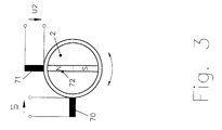
- Fig. 3 shows an embodiment with two fixed, on one Circumference arranged at a distance of 90 °, bipolar Pulse wire motion sensors 70, 71 and one with the rotating shaft 2 connected permanent magnet 72 according to dependent claim 8.
- bipolar pulse wire motion sensors deliver unipolar effects a voltage pulse during both the switching and the resetting process.
- the advantage of this arrangement is the implementation with the least possible Number of motion sensors.
- Fig. 4 shows an embodiment with two fixed, on one Circumference arranged at a distance of 180 °, bipolar Pulse wire motion sensors consisting of two sensor coils 90, 91, two permanent magnets 92, 93 assigned to sensor coil 90, two of the sensor coil 91 assigned permanent magnets 94, 95 and one with the rotary shaft 2 connected pulse wire 96 according to dependent claim 11.
- the sensor coil of the Pulse wire motion sensor separately from the pulse wire in a known manner arranged between two oppositely polarized permanent magnets.
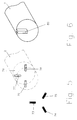
- FIG. 5 shows a mechanical arrangement of three motion sensors 73, 74, 75, a switching permanent magnet 77 and two reset permanent magnets 76, 78 according to dependent claim 7.
- the magnetically effective axes of Motion sensors and permanent magnets are radial to the axis of the rotary shaft 2 oriented.
- the permanent magnets attached to the end of the rotating shaft are in one Embedded shaft piece 79 made of magnetically non-conductive material, so that The structure of the magnetic fields remains unaffected by the material of the rotating shaft.
- An arrangement in this form allows the construction of an inventive one Angle of rotation sensor with small outer circumference.
- Fig. 6 shows a mechanical design according to dependent claim 10.
- One each Form a bipolar pulse wire motion sensor and two permanent magnets in a known manner a unit of which three correspond to the Motion sensors 73, 74, 75 in Fig. 5 are arranged fixed.
- the Magnetization of the motion sensors is caused by a movable, on the shaft attached flow guide 80 controlled.
- the magnetic flux of both Permanent magnets penetrate each other in opposite directions via air gaps Motion sensor (pulse wire and the sensor coil wound on it).
- the magnetic flux becomes one of the magnets amplified and the motion sensor magnetized. Accordingly, the Motion sensor magnetized in another direction when the flux guide on the other air gap is brought up.
- the advantage of this embodiment is in the particularly simple design of the movable parts of the Arrangement.
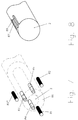
- FIG. 7 shows another mechanical arrangement of three Motion sensors 80 ', 81, 82, a switching permanent magnet 83 and two Reset permanent magnets 84, 85 according to dependent claim 7.
- the magnetic effective axes of motion sensors and permanent magnets oriented axially parallel to the rotary shaft 2.
- the attached at the end of the rotating shaft Permanent magnets are in a shaft piece 86 made of magnetically non-conductive material embedded so that the structure of the magnetic fields is unaffected by the material the rotating shaft remains.
- Fig. 8 shows a mechanical design according to dependent claim 9.
- One each unipolar (see FIG. 6) acting pulse wire motion sensor and two Permanent magnets form a unit of which three in a known manner corresponding to the motion sensors 80 ', 81, 82 in Fig. 7 fixed are arranged.
- the magnetization of the motion sensors is done by two movable flux guide pieces 87, 88 attached to the shaft 2 as in FIG. 6 described controlled.
- the advantage of this embodiment lies next to that particularly simple design of the movable parts of the Arrangement in the short design.
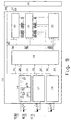
- Fig. 9 shows the execution of an electronic counter circuit 13 dependent claims 2, 3, 4, 5, 12, consisting of three identically designed Pulse shaping circuits 16, 17, 18, a control circuit 19, one settable up / down counter 22, a non-volatile read / write memory 21 and an evaluation and interface circuit 20.
- Each of the pulse shaping circuits consists of a diode 23, a charging capacitor 24, a Discharge resistor 25, an electronic switch 26 and a diode 27. Die generated by the voltage-generating movement sensors 6, 7, 8 Pulse voltages U1, U2, U3 are the three pulse shaping circuits 16, 17, 18 fed. Charges in the forward direction via the diode 23 Voltage pulse the charging capacitor 24.
- the capacitor voltage is the series circuit of electronic Switch 26 and discharge resistor 25 supplied.
- Logic signals "charging capacitor discharge "31, 32, 33 for discharging the charging capacitors are the supplied electronic switches from the control circuit 19. Via the diode 27 becomes a condenser voltage in the forward direction Auxiliary supply voltage formed on a line 34.
- the Auxiliary supply voltage is the supply voltage inputs of the Control circuit 19, the up / down counter 22 and the non-volatile memory 21 fed.
- the non-volatile memory is made in ferroelectric technology.
- Non-volatile read / write memory 21 as a static semiconductor memory in CMOS technology with a Buffer battery or a buffer capacitor executed. Since the Motion sensors do not require a supply voltage, this indicates Embodiment an advantageously low supply current for operation of the non-volatile memory, so that the backup batteries have a longer life Lifespan remain usable.
- the voltage pulses U1, U2, U3 cause one revolution of the shaft in three sectors I, II, III divided.
- the occurrence of a voltage pulse U1 shows when turning to the left, the transition of the shaft rotation angle from sector III to Sector I on, when turning to the right the transition from sector I to sector III.
- the angular position of the Rotary shaft can thus by evaluating the voltage pulses U1, U2, U3 given states taking into account past states U1 (-1), U2 (-1), U3 (-1) can be assigned to one of the sectors I, II or III.
- the number of shaft revolutions can be as follows, below shown, evaluation of the voltage pulses are counted.
- the state vector "last revolution state” Z and the logic signal “Counting direction” are stored in the non-volatile memory.
- the control sequence causes the up / down counter to contain the content of the non-volatile memory loaded, depending on the pulse voltage vector Y, State vector "last revolution state” Z and count direction bit RB incremented or decremented and back into the non-volatile memory is transferred back.
- Equations (G10) and (G11) state that each pulse U1 of the Motion sensor 6 with monotonous rotary movement of the rotary shaft 2 in positive or negative direction of rotation the up / down counter by the value "1" incremented or decremented.
- the equations (G12) and (G13) state that that after reversing the direction of rotation, if necessary, the pulses U2, U3 Motion sensors 7 and 8 for incrementing or decrementing the Revolution counter are evaluated.
- the evaluation and interface circuit 20 combines the measured value of the fine angle of rotation sensor and the value of the revolution counter stored in the non-volatile memory to form an absolute measured value for the angle of rotation. Since the relative position of the voltage-generating movement sensors 6, 7, 8 with respect to the position of the fine rotation angle sensor is subject to manufacturing and component tolerances, the value of the fine rotation angle sensor 3, which is in the non-volatile memory, must be determined in order to determine the absolute angular position WA of the rotary shaft 21 stored counter reading, the state vector "last state of revolution" Z and the count direction bit are evaluated.
- This evaluation also takes into account the transition states occurring in connection with a reversal of the direction of rotation according to equations (G12) and (G13); it synchronizes the information of the revolution counter with the angular position of the fine rotation angle sensor.
- the result is a corrected counter reading N 'as a function of the angular position of the fine rotation angle sensor, the state vector "last state of rotation” Z and the "counting direction" RB.
- the absolute angular position is determined by the evaluation and interface circuit 20 over the data interface with lines 14 of the parent Unit 15 fed.
- the transmission usually has to be set to a predetermined value a numerical value from the higher-level unit 15 in the non-volatile Memory of the rotation angle sensor provided.
- Fig. 11 shows an alternative graphical representation form of the in the Equations G1 to G14 described logical relationships for counting the Shaft revolutions in the form of a state diagram. After that is the Movement of the rotating shaft using four logic states S (1L) 100, S (1R) 101, S (2) 102, S (3) 103 and ten state transitions corresponding to the Shaft revolution shown in clockwise or counter-clockwise.
- the state transitions occur when the shaft rotates monotonically to the left 104, 107, 110 with incrementing the up / down counter at transition 104.
- the state transitions 106, 108, 111 occur with a monotonous clockwise rotation Decrement the up / down counter at transition 108.
- When changing direction of rotation state transitions 112 and 113 take place within sectors 1 and III without influencing counter or direction bit.
- State transition 105 When changing direction from Left turn after right turn with leaving sectors I and III State transition 105 with decrementing the counter.
- the direction bit logic "1" is set at the state transitions 107, 109, 110, 104, it becomes logic "0" set at the state transitions 105, 106, 108, 111. Die The direction bit is evaluated before the corresponding one is executed State transition, the update takes place afterwards.
Description
Die Erfindung betrifft einen Drehwinkelsensor der im Oberbegriff des Anspruchs 1
beschriebenen Art.The invention relates to an angle of rotation sensor in the preamble of
Aus der DE 41 37 092 A1 ist ein Drehwinkelsensor mit einem Winkelcodierer bekannt, bei dem es sich um eine abgetastete Codescheibe handeln kann und der die Winkelstellung einer Welle über eine Umdrehung erfaßt. Ein der Codescheibe nachgeordnetes Potentiometer erfaßt die absolute Winkelstellung der Welle über mehrere Umdrehungen. Eine nachgeordnete Auswerteschaltung ordnet der Winkelstellung der Codescheibe eine zugehörige Umdrehungszahl unter Berücksichtigung von Getriebespiel und Meßwertfehlern des Potentiometers zu. Drehwinkelsensoren dieser Bauweise liefern unabhängig von zwischenzeitlichen Unterbrechungen der Versorgungsspannung immer den absoluten Drehwinkel über mehrere Umdrehungen. Nachteilig ist der hohe Herstellungsaufwand für Getriebestufen und Sensorelemente sowie eine begrenzte Lebensdauer aufgrund vieler mechanisch bewegter Teile. Die Anzahl der erfaßbaren Umdrehungen ist aufgrund der mechanischen Ausführung begrenzt.DE 41 37 092 A1 discloses an angle of rotation sensor with an angle encoder known, which can be a scanned code disc and the the angular position of a shaft detected over one revolution. One of the code disks Downstream potentiometer detects the absolute angular position of the shaft several turns. A downstream evaluation circuit assigns the Angular position of the code disk under an associated number of revolutions Consideration of gear play and measured value errors of the potentiometer. Rotation angle sensors of this design deliver irrespective of intermediate ones Interruptions in the supply voltage always exceed the absolute angle of rotation several turns. The disadvantage is the high production cost for Gear stages and sensor elements as well as a limited service life due to many mechanically moving parts. The number of revolutions that can be detected is limited due to the mechanical design.
Aus der DE 37 29 949 A1 ist ein Drehwinkelsensor mit einer Zählanordnung Z, mehreren, versetzt auf einem Kreisumfang feststehend angeordneten Impulsdraht-Bewegungssensoren S1 bis S6 und mehreren Magneten M bekannt. Die Ausgangsimpulse der Impulsdraht-Bewegungssensoren werden der Zählanordnung so zugeführt, daß der Zählstand der Zählanordnung ein Maß für die Drehlage eines mit einer Welle verbundenen Geberrades ist. Der Nachteil dieser Anordnung besteht darin, daß die Zählanordnung bei Ausbleiben der Versorgungsspannung ihre Funktion verliert, so daß Bewegungen der Welle nicht mehr erfaßt werden und der aktuelle Zählstand verloren geht. DE 37 29 949 A1 describes a rotation angle sensor with a counting arrangement Z, several pulse wire motion sensors arranged fixed on a circumference S1 to S6 and several magnets M known. The Output pulses from the pulse wire motion sensors become the counting arrangement fed so that the count of the counting arrangement is a measure of the rotational position of a encoder wheel connected to a shaft. The disadvantage of this arrangement is in that the counting arrangement in the absence of the supply voltage Function loses, so that movements of the shaft are no longer detected and the current count is lost.
Ein Drehwinkelsensor der genannten Art ist durch das Produkt CE100 der Firma T+R, Trossingen bekannt. Ein Fein-Sensorelement erfaßt die Winkelstellung einer Welle über eine Umdrehung, und die Meßwerte wiederholen sich periodisch mit jeder Umdrehung. Über Getriebe sind ein oder mehrere Grob-Sensorelemente hinter das Fein-Sensorelement gekoppelt. Der absolute Meßwert ergibt sich aus der geeigneten Kombination der Meßwerte des Fein-Sensorelements und der Grob-Sensorelemente. Drehwinkelsensoren dieser Bauweise liefern unabhängig von zwischenzeitlichen Unterbrechungen der Versorgungsspannung immer den absoluten Drehwinkel über eine große Anzahl von Umdrehungen. Nachteilig ist der hohe Herstellungsaufwand für Getriebestufen und Sensorelemente sowie eine begrenzte Lebensdauer aufgrund vieler mechanisch bewegter Teile. Die Anzahl der erfaßbaren Umdrehungen ist aufgrund der mechanischen Ausführung begrenzt.A rotation angle sensor of the type mentioned is through the product CE100 from the company T + R, Trossingen known. A fine sensor element detects the angular position of a Shaft over one revolution, and the measured values are repeated periodically with every turn. One or more coarse sensor elements are behind the transmission the fine sensor element coupled. The absolute measured value results from the suitable combination of the measured values of the fine sensor element and the coarse sensor elements. Rotation angle sensors of this design deliver independently of intermittent interruptions of the supply voltage always the absolute angle of rotation over a large number of revolutions. The disadvantage is that high manufacturing costs for gear stages and sensor elements as well as a limited lifespan due to many mechanically moving parts. The number of detectable revolutions is limited due to the mechanical design.
Ein weiterer Drehwinkelsensor der genannten Art ist durch das Produkt OAM-74-11/24bit-LPS-5V (TS5778N10) der Firma Tamagawa Seiki Co., Tokio bekannt. Eine Meßanordnung erfaßt die Winkelbewegungen einer Welle. Mit einem Zhäler werden inkrementale Wellenwegungen unter Berücksichtigung der Bewegungsrichtung über mehrere Umdrehungen zu einem absoluten Meßwert aufaddiert. Bei Versorgungsspannungsausfall wird der Betrieb des Drehwinkelsensors durch eine Pufferbatterie sichergestellt. Auch langdauernde Unterbrechungen der Versorgungsspannung bei Stillstandszeiten müssen durch die Pufferbatterie überbrückt werden. Der Aufwand für die Realisierung ist bei dieser Ausführungsform geringer als bei Sensoren mit getriebegekoppelten Winkel sensorelementen. Der Nachteil dieses Winkelsensors ist die begrenzte Lebensdauer der Pufferbatterien. Diese müssen in bestimmten Zeitabständen ersetzt werden. Ein weiterer Nachteil ist die Notwendigkeit, die Sensorelemente aus der Pufferbatterie zu speisen und die damit verbundene zusätzliche Batteriebelastung. Unter extremen Umweltbedingungen wie hohen oder niedrigen Temperaturen sind Batterien nicht einsetzbar.Another rotation angle sensor of the type mentioned is the product OAM-74-11 / 24bit-LPS-5V (TS5778N10) from Tamagawa Seiki Co., Tokyo. A Measuring arrangement detects the angular movements of a shaft. With a counter incremental wave movements taking into account the direction of movement added several revolutions to an absolute measured value. In the event of a supply voltage failure the rotation angle sensor is operated by a backup battery ensured. Even long interruptions in the supply voltage Downtimes must be bridged by the backup battery. The effort for the implementation in this embodiment is less than with sensors gear coupled angle sensor elements. The disadvantage of this angle sensor is the limited life of the backup batteries. These must be in certain Intervals are replaced. Another disadvantage is the need for that To feed sensor elements from the backup battery and the associated additional battery usage. Under extreme environmental conditions such as high or Batteries cannot be used at low temperatures.
Aus der EP-A-0 342 375 ist ein Drehwinkelsensor gemäß dem Oberbegriff des
Patentanspruchs 1 bekannt. Dieser Drehwinkelsensor enthält einen mit einer
Drehwelle verbundenen Fein-Drehwinkelsensor, der den Winkel innerhalb einer
Umdrehung mißt. Eine Zählschaltung verarbeitet die Signale einer Zählanordnung,
die aus drei versetzt auf einem Kreisumfang feststehend angeordneten
Impulsdrahtsensoren, einem Dauermagneten und der elektronischen Zählschaltung
besteht. Die Zählschaltung ist jedoch nicht ausfallsicher gebildet, da eine externe
Energieversorgung dauerhaft notwendig ist.From EP-A-0 342 375 is a rotation angle sensor according to the preamble of
Das Dokument EP-A-0 449 037 beschreibt ebenfalls einen Drehwinkelsensor mit einem nicht-flüchtigen Speicher, der auch bei Stromunterbrechung die eingeschriebenen Daten behält. Zur Versorgung der einzelnen Schaltkreise dieses Drehwinkelsensors ist jedoch auch hier eine externe Energiequelle erforderlich. Bei einem Ausfall der Versorgungsspannung ist die Funktion des Drehwinkelsensors daher nicht gewährleistet.Document EP-A-0 449 037 also describes a rotation angle sensor a non-volatile memory, which even when the power supply is interrupted retains registered data. To supply the individual circuits this However, an external energy source is also required here. At a failure of the supply voltage is the function of the angle sensor therefore not guaranteed.
Demgegenüber liegt der Erfindung die Aufgabe zugrunde, einen Drehwinkelsensor der eingangs genannten Art so weiterzubilden, daß bei einem Ausbleiben der von außen zugeführten Versorgungsspannung die Wellenumdrehungen ohne mechanisches Getriebe und ohne Versorgung aus Batterien gezählt werden.In contrast, the invention has for its object a rotation angle sensor of the type mentioned in such a way that in the absence of the shaft revolutions without externally supplied supply voltage mechanical gear and can be counted without supply from batteries.
Zur Lösung dieser Aufgabe sieht die Erfindung einen Drehwinkelsensor mit den im Anspruch 1 niedergelegten
Merkmalen vor.
Bei diesem Drehwinkelsensor ist ein nichtflüchtiger
Schreib-/Lesespeicher zum Speichern der Anzahl
der Wellenumdrehungen vorhanden und ein Teil
der von den Impulsdraht-Bewegungssensoren
gelieferten elektrischen Energie wird der elektronischen
Zählschaltung zwecks Energieversorgung zugeführt.
Dadurch wird
vorteilhaft ohne Zufuhr einer von außen anliegenden oder in Batterien
gespeicherten Spannung die Anzahl der Wellenumdrehungen erfaßt. Weitere
vorteilhafte Weiterbildungen eines erfindungsgemäßen Drehwinkelsensors sind in
den abhängigen Ansprüchen niedergelegt. To achieve this object, the invention provides a rotation angle sensor with the one set out in
Die Erfindung wird im folgenden anhand von Ausführungsbeispielen unter Bezugnahme auf die Zeichnung erläutert.The invention is described below using exemplary embodiments Explained with reference to the drawing.
In dieser zeigen
Der in Fig. 1 dargestellte Drehwinkelsensor 1 besteht aus einer Drehwelle 2,
einem mit der Drehwelle verbundenen Fein-Drehwinkelsensor 3 zur
Drehwinkelmessung über eine Umdrehung und einer Zählanordnung 4 zur
Zählung der ganzen Umdrehungen der Drehwelle. Die Zählanordnung dieser
Ausführungsform weist Impulsdraht-Bewegungssensoren 6, 7, 8, mit der Welle
verbundene Dauermagneten 10, 11, 12 und eine elektronische Zählschaltung 13
auf. Der Zählschaltung wird der Meßwert des Fein-Drehwinkelsensors über
Leitungen 59 und Spannungsimpulse 28, 29, 30 von den Bewegungssensoren
zugeführt. Der Fein-Drehwinkelsensor ist in bekannter Weise, z. B. als optischer
Enkoder oder Resolver, ausgeführt. Über eine Datenschnittstelle mit Leitungen 14
und Leitungen 58 zur Spannungsversorgung ist die Zählschaltung mit einer
übergeordneten Einheit 15 verbunden. The
Fig. 2, Fig. 3 und Fig. 4 zeigen verschiedene grundsätzliche Ausführungsformen zur Anordnung von Impulsdraht-Bewegungssensoren, Dauermagneten und Flußleitstücken. Vorbestimmten Winkelstellungen der Drehwelle 2 sind die Spannungsimpulse der Bewegungssensoren zugeordnet. Unter Einbeziehen vergangener Drehzustände durch Berücksichtigung zeitlich zurückliegender Spannungsimpulse ermöglicht dies:
- das Erfassen jeder vollen Umdrehung der
Drehwelle 2, - das Berücksichtigen der Drehrichtung der Drehwelle,
- das Berücksichtigen der für Wiegandsensoren charakteristischen Positionsdifferenz zwischen Setz- und Rücksetzvorgang,
- die eindeutige Zuordnung der Spannungsimpulse der Bewegungssensoren
zur Anzahl der Wellenumdrehungen durch Kombination eines durch die
Spannungsimpulse definierten Umdrehungszustandes mit der Stellung des Fein-
Drehwinkelsensors 3 auch bei mechanisch oder magnetisch verursachten Toleranzen der Winkellage der Spannungsimpulse
- the detection of every full revolution of the
rotary shaft 2, - taking into account the direction of rotation of the rotating shaft,
- taking into account the positional difference between the setting and resetting process which is characteristic of Wiegand sensors,
- the unambiguous assignment of the voltage pulses of the motion sensors to the number of shaft revolutions by combining a state of rotation defined by the voltage pulses with the position of the fine
rotation angle sensor 3 even with tolerances in the angular position of the voltage pulses caused mechanically or magnetically
Fig. 2 zeigt eine Ausführungsform mit drei feststehenden, auf einem
Kreisumfang im Abstand von 120° Grad angeordneten, unipolar wirkenden
Impulsdraht-Bewegungssensoren 6, 7, 8, einen mit der Drehwelle 2 verbundenen
Schalt-Dauermagnet 10 und zwei mit der Drehwelle verbundene Rücksetz-Dauermagneten
11, 12 entsprechend abhängigem Anspruch 7. Die Impulsdraht-Bewegungssensoren,
auch Wiegand-Sensoren genannt, sind bei dieser
Ausführungsform in bekannter Weise als mit Sensorspulen bewickelte
Impulsdrahtabschnitte ausgeführt. Durch Drehung der Welle werden Schalt- und
Rücksetzmagnete an den Bewegungssensoren so vorbeigeführt, daß das
Magnetfeld der Schalt- und Rücksetzmagnete den Impulsdraht der
Bewegungssensoren mit jeweils umgekehrter Polarität durchsetzt. Das
Vorbeiführen des Schalt-Dauermagnet 10 vor einem der Bewegungssensoren
erzeugt in bekannter Weise durch das gleichzeitige Ummagnetisieren aller
magnetischen Domänen (Weiß'schen Bezirke) des Impulsdrahtes kurzzeitige
Spannungsimpulse von definierter Länge und Amplitude in der Sensorspule. Das
Vorbeiführen eines der Rücksetz-Dauermagnete 11, 12 setzt den
Magnetisierungszustand des Bewegungssensors wieder zurück. Unipolar
wirkende Impulsdraht-Bewegungssensoren liefern in bekannter Weise nur beim
Schaltvorgang, nicht aber beim Rücksetzvorgang einen Spannungsimpuls. Bipolar
wirkende Impulsdraht-Bewegungssensoren liefern sowohl beim Schaltvorgang als
auch beim Rücksetzvorgang einen Spannungsimpuls. Impulslänge und -amplitude
sind unabhängig von der Bewegungsgeschwindigkeit der Schalt- und
Rücksetzmagnete. Schaltmagnet und Rücksetzmagnete sind auf dem Rotor so
angeordnet, daß nach Vorbeiführen des Schaltmagneten immer ein
Rücksetzmagnet an einem Bewegungssensor vorbeigeführt wird, bevor der
Schaltmagnet an einem der beiden anderen Bewegungssensoren vorbeigeführt
wird. Der Vorteil der Anordnung nach Fig. 2 ist die von unipolar wirkenden
Impulsdraht-Bewegungssensoren erzeugte hohe Spannungsamplitude.Fig. 2 shows an embodiment with three fixed, on one
Circumference arranged at a distance of 120 °, acting unipolar
Pulse
Fig. 3 zeigt eine Ausführungsform mit zwei feststehenden, auf einem
Kreisumfang im Abstand von 90° Grad angeordneten, bipolar wirkenden
Impulsdraht-Bewegungssensoren 70, 71 und einen mit der Drehwelle 2
verbundenen Dauermagnet 72 entsprechend abhängigem Anspruch 8. Im Gegensatz zu
unipolar wirkenden liefern bipolar wirkende Impulsdraht-Bewegungssensoren
sowohl beim Schalt- als auch beim Rücksetzvorgang einen Spannungsimpuls.
Der Vorteil dieser Anordnung ist die Realisierung mit der geringstmöglichen
Anzahl von Bewegungssensoren.Fig. 3 shows an embodiment with two fixed, on one
Circumference arranged at a distance of 90 °, bipolar
Pulse
Fig. 4 zeigt eine Ausführungsform mit zwei feststehenden, auf einem
Kreisumfang im Abstand von 180° Grad angeordneten, bipolar wirkenden
Impulsdraht-Bewegungssensoren bestehend aus zwei Sensorspulen 90, 91, zwei
der Sensorspule 90 zugeordneten Dauermagneten 92, 93, zwei der Sensorspule
91 zugeordneten Dauermagneten 94, 95 und einen mit der Drehwelle 2
verbundenen Impulsdraht 96 entsprechend abhängigem Anspruch 11. Im Gegensatz zu
den vorangegangenen Beispielen nach Fig. 2 und Fig. 3 ist die Sensorspule des
Impulsdraht-Bewegungssensors in bekannter Weise getrennt vom Impulsdraht
zwischen zwei gegensinnig gepolten Dauermagneten angeordnet. Das
Vorbeiführen des Impulsdrahtes an den Magneten und der Sensorspule durch
Drehung der Welle löst zwei Ummagnetisierungsvorgänge des Impulsdrahtes
aus, von denen, auf Grund der geometrischen Anordnung, nur einer das die
Sensorspule durchsetzende Magnetfeld so beeinflußt, daß ein Spannungsimpuls
induziert wird. Diese Anordnung liefert Spannungsimpulse, deren Polarität die
Drehrichtung anzeigen.Fig. 4 shows an embodiment with two fixed, on one
Circumference arranged at a distance of 180 °, bipolar
Pulse wire motion sensors consisting of two
Fig. 5 zeigt eine mechanische Anordnung von drei Bewegungssensoren 73,
74, 75, einem Schalt-Dauermagnet 77 und zwei Rücksetz-Dauermagneten 76, 78
nach abhängigem Anspruch 7. Die magnetisch wirksamen Achsen von
Bewegungssensoren und Dauermagneten sind radial zur Achse der Drehwelle 2
orientiert. Die am Drehwellenende angebrachten Dauermagnete sind in ein
Wellenstück 79 aus magnetisch nichtleitendem Material eingebettet, damit der
Aufbau der magnetischen Felder unbeeinflußt vom Material der Drehwelle bleibt.
Eine Anordnung in dieser Form erlaubt den Aufbau eines erfindungsgemäßen
Drehwinkelsensors mit kleinem Außenumfang.5 shows a mechanical arrangement of three
Fig. 6 zeigt eine mechanische Ausführung nach abhängigem Anspruch 10. Je ein
bipolar wirkender Impulsdraht-Bewegungssensor und zwei Dauermagnete bilden
in bekannter Weise eine Einheit von denen drei entsprechend den
Bewegungssensoren 73, 74, 75 in Fig. 5 feststehend angeordnet sind. Die
Magnetisierung der Bewegunssensoren wird durch ein bewegliches, an der Welle
angebrachtes Flußleitstück 80 gesteuert. Der magnetische Fluß beider
Dauermagnete durchsetzt jeweils gegensinnig über Luftspalte den
Bewegungssensor (Impulsdraht und die darauf gewickelte Sensorspule). Bei
Überbrücken eines der Luftspalte durch Heranführen des beweglich
angeordneten Flußleitstückes 80 wird der magnetische Fluß eines der Magnete
verstärkt und der Bewegungssensor ummagnetisiert. Entsprechend wird der
Bewegungssensor in anderer Richtung ummagnetisiert wenn das Flußleitstück an
den anderen Luftspalt herangeführt wird. Der Vorteil dieser Ausführungsform liegt
in der besonders einfachen Gestaltung der beweglich auszuführenden Teile der
Anordnung.Fig. 6 shows a mechanical design according to
Fig. 7 zeigt eine weitere mechanische Anordnung von drei
Bewegungssensoren 80', 81, 82, einem Schalt-Dauermagnet 83 und zwei
Rücksetz-Dauermagneten 84, 85 nach abhängigem Anspruch 7. Die magnetisch
wirksamen Achsen von Bewegungssensoren und Dauermagneten sind
achsparallel zur Drehwelle 2 orientiert. Die am Drehwellenende angebrachten
Dauermagnete sind in ein Wellenstück 86 aus magnetisch nichtleitendem Material
eingebettet, damit der Aufbau der magnetischen Felder unbeeinflußt vom Material
der Drehwelle bleibt. Eine Anordnung in dieser Form erlaubt den Aufbau eines
erfindungsgemäßen Drehwinkelsensors in besonders kurzer Bauweise.7 shows another mechanical arrangement of three
Fig. 8 zeigt eine mechanische Ausführung nach abhängigem Anspruch 9. Je ein
unipolar (vgl. Fig. 6) wirkender Impulsdraht-Bewegungssensor und zwei
Dauermagnete bilden in bekannter Weise eine Einheit von denen drei
entsprechend den Bewegungssensoren 80', 81, 82 in Fig. 7 feststehend
angeordnet sind. Die Magnetisierung der Bewegunssensoren wird durch zwei
bewegliche, an der Welle 2 angebrachten Flußleitstücke 87, 88 wie in Fig. 6
beschrieben gesteuert. Der Vorteil dieser Ausführungsform liegt neben der
besonders einfachen Gestaltung der beweglich auszuführenden Teile der
Anordnung in der kurzen Bauform.Fig. 8 shows a mechanical design according to dependent claim 9. One each
unipolar (see FIG. 6) acting pulse wire motion sensor and two
Permanent magnets form a unit of which three in a known manner
corresponding to the
Fig. 9 zeigt die Ausführung einer elektronischen Zählschaltung 13 nach
den abhängigen Ansprüchen 2, 3, 4, 5, 12, bestehend aus drei gleich ausgeführten
Impulsformungs-Schaltungen 16, 17, 18, einer Steuerschaltung 19, einem
setzbaren Auf-/Abzähler 22, einem nichtflüchtigen Schreib-/Lesespeicher 21 und
einer Auswerte- und Schnittstellen-Schaltung 20. Jede der Impulsformungs-Schaltungen
besteht aus einer Diode 23, einem Ladekondensator 24, einem
Entladewiderstand 25, einem elektronischen Schalter 26 und einer Diode 27. Die
von den spannunggenerierenden Bewegungssensoren 6, 7, 8 erzeugten
Impulsspannungen U1, U2, U3 werden den drei Impulsformungs-Schaltungen 16,
17, 18 zugeführt. Über die Diode 23 in Durchlassrichtung lädt ein
Spannungsimpuls den Ladekondensator 24. Die Spannung der
Ladekondensatoren wird als Impulsspannungsvektor Y = [Y1, Y2, Y3] bestehend
aus den analogen Signalen Y1, Y2, Y3, 28, 29, 30 der Steuerschaltung 19
zugeführt. Die Kondensatorspannung ist der Reihenschaltung aus elektronischem
Schalter 26 und Entladewiderstand 25 zugeführt. Logiksignale "Ladekondensator
entladen" 31, 32, 33 zum Entladen der Ladekondensatoren sind den
elektronischen Schaltern von der Steuerschaltung 19 zugeführt. Über die Diode
27 wird in Durchlaßrichtung aus der Kondensatorspannung eine
Hilfsversorgungsspannung auf einer Leitung 34 gebildet. Die
Hilfsersorgungsspannung ist den Versorgungsspannungseingängen der
Steuerschaltung 19, des Auf/Abwärtszählers 22 und des nichtflüchtigen Speichers
21 zugeführt. Über die Diode 60 in Durchlaßrichtung ist die von außen über die
Leitung 58 zugeführte Versorgungsspannung mit der Hilfsversorgungsspannung
verbunden. Somit werden im normalen Betriebsfall bei anstehender
Versorgungsspannung Steuerschaltung, Auf/Abwärtszähler und nichtflüchtiger
Speicher zur Zählung der Wellenumdrehungen aus der von außen zugeführten
Versorgungsspannung versorgt. Bei Ausbleiben der von außen zugeführten
Versorgungsspannung werden der Fein-Drehwinkelsensor und die Auswerte- und
Schnittstellenschaltung nicht mehr mit Spannung versorgt, die Zählung der
Wellenumdrehungen wird durch die aus der Impulsformungs-Schaltung
abgeleiteten Hilfsversorgungsspannung fortgeführt. Die Steuerschaltung 19 gibt
ein Logiksignal "Ausgabe bereit" 36 zur Steuerung der Übergabe von
Umdrehungswerten an die Auswerte- und Schnittstellen-Schaltung 20 und die
Logiksignale "In nichtflüchtigen Speicher schreiben" 37 und "Aus nichtflüchtigem
Speicher lesen" 38 zur Steuerung des nichtflüchtigen Speicher 21 aus. Weiterhin
ist die Steuerschaltung über ein Logiksignal "Zählrichtung" 42 sowie einen
Zustandsvektor "Letzter Umdrehungszustand" Z = [Z1, Z2, Z3] bestehend aus den
Logiksignalen Z1, Z2, Z3 43, 44, 45 mit dem nichtflüchtigen Speicher verbunden.
Weiterhin gibt die Steuerschaltung Logiksignale "Takt" 39, "Auf/Ab" 40 und
"Zähler setzen" 41 an den Auf/Abwärtszähler aus. Für das Laden und
Zurückschreiben der Umdrehungszahl ist der Auf/Abwärtszähler mit dem
nichtflüchtigen Speicher über ein Datenwort "Umdrehungen", bestehend aus den
Datenbit D0, D1, ... Dn 46, 47, 48, .. 49, verbunden. Der nichtflüchtige Speicher
ist mit der Auswerte- und Schnittstellen-Schaltung 20 über die Logiksignale
"Zählrichtung-Ausgabe" 50 sowie einen Zustandsvektor "Letzter
Umdrehungszustand-Ausgabe" Z' = [Z1', Z2', Z3'] bestehend aus den
Logiksignalen Z1', Z2', Z3' 51, 52, 53 und über ein Datenwort "Umdrehungen-Ausgabe",
bestehend aus den Datenbit D0', D1', ... Dn' 54, 55, 56, .. 57, mit der
Auswerte- und Schnittstellen-Schaltung verbunden. Der nichtflüchtige Speicher ist
in ferroelektrischer Technologie ausgeführt. Er besteht aus einem Datenwort,
aufgeteilt auf beispielsweise zwölf Bit als Speicher für die Umdrehungszahl, drei
Bit als Speicher für den Zustandsvektor "Letzter Umdrehungszustand" Z und ein
Bit für die "Zählrichtung" 42. Speicherbausteine in ferroelektrischer
Speichertechnologie zeichnen sich durch besonders geringen Stromverbrauch
und durch schnellen Lese- und Schreibzugriff aus. Das Speicherelement der
ferroelektrischen Speichertechnologie ist ein elektrischer Kristall-Dipol. Ähnlich
einem ferromagnetischem Dipol ändert dieser seine Ausrichtung durch Anlegen
eines elektrischen Feldes und hält diese ohne Versorgungsspannung. In einer
anderen Ausführungsform nach abhängigem Anspruch 6 wird der nichtflüchtige Schreib-/Lesespeicher
21 als statischer Halbleiterspeicher in CMOS Technologie mit einer
Pufferbatterie oder einem Pufferkondensator ausgeführt. Da die
Bewegungssensoren keine Versorgungsspannung benötigen, weist diese
Ausführungsform einen vorteilhaft niedrigen Versorgungsstrom für den Betrieb
des nichtflüchtigen Speichers auf, so daß die Pufferbatterien über eine längere
Lebensdauer verwendbar bleiben.Fig. 9 shows the execution of an
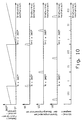
Fig. 10 zeigt beispielhaft die von den drei Impulsdrahtsensoren 6, 7, 8
erzeugten Spannungsimpulse und deren Zuordnung zum absoluten Drehwinkel
der Drehwelle 2:
Durch die Spannungsimpulse U1, U2, U3 wird eine Umdrehung der Welle in drei Sektoren I, II, III eingeteilt. Das Auftreten eines Spannungsimpulses U1 zeigt bei Linksdrehung den Übergang des Wellendrehwinkels von Sektor III nach Sektor I an, bei Rechtsdrehung den Übergang von Sektor I nach Sektor III. Entsprechendes gilt für die Spannungsimpulse U2, U3. Die Winkelstellung der Drehwelle kann somit durch Auswertung der durch die Spannungsimpulse U1, U2, U3 gegebenen Zustände bei Berücksichtigung von vergangenen Zuständen U1(-1), U2(-1), U3(-1) einem der Sektoren I, II oder III zugeordnet werden. Die Anzahl der Wellenumdrehungen kann bei entsprechender, nachfolgend dargestellten, Auswertung der Spannungsimpulse gezählt werden.The voltage pulses U1, U2, U3 cause one revolution of the shaft in three sectors I, II, III divided. The occurrence of a voltage pulse U1 shows when turning to the left, the transition of the shaft rotation angle from sector III to Sector I on, when turning to the right the transition from sector I to sector III. The same applies to the voltage pulses U2, U3. The angular position of the Rotary shaft can thus by evaluating the voltage pulses U1, U2, U3 given states taking into account past states U1 (-1), U2 (-1), U3 (-1) can be assigned to one of the sectors I, II or III. The The number of shaft revolutions can be as follows, below shown, evaluation of the voltage pulses are counted.
Nachfolgend wird für eine Anordnung nach abhängigem Anspruch 7 das
Zusammenwirkungen der Bewegungssensoren 6, 7, 8, der elektronischen
Zählschaltung 13, der Impulsformungs-Schaltungen 16, 17, 18, der
Steuerschaltung 19, dem setzbaren Auf-/Abzähler 22, dem nichtflüchtigen
Schreib-/Lesespeicher 21 und der Auswerte- und Schnittstellen-Schaltung 20
anhand von logischen Beziehungen und Steuersequenzen beschrieben.Below is that for an arrangement according to
Der "Impulsspannungsvektor" Y = [Y1, Y2, Y3] nimmt die Werte Y = [100], Y
= [010], und Y = [001] mit folgender Bedeutung an:
Der Zustandsvektor "Letzter Umdrehungszustand" Z = [Z1, Z2, Z3] nimmt
die Werte Z = [100], Z = [010] und Z = [001] mit folgender Bedeutung an:
Das Logiksignal "Zählrichtung" RB hat folgende Bedeutung
Der Zustandsvektor "Letzter Umdrehungszustand" Z und das Logiksignal "Zählrichtung" werden im nichtflüchtigen Speicher abgelegt. The state vector "last revolution state" Z and the logic signal "Counting direction" are stored in the non-volatile memory.
Nach Aufbau der Hilfsversorgungspannung UV' als Folge eines
Spannungsimpulses von einem der Bewegungssensoren arbeitet die
Steuerschaltung folgende Steuersequenz ab:
Die Steuersequenz bewirkt, daß der Auf-/Abwärtszähler mit dem Inhalt des nichtflüchtigen Speichers geladen, abhängig vom Impulsspannungsvektor Y, Zustandsvektor "Letzter Umdrehungszustand" Z und Zählrichtungsbit RB inkrementiert bzw. dekrementiert und wieder in den nichtflüchtigen Speicher zurückübertragen wird. The control sequence causes the up / down counter to contain the content of the non-volatile memory loaded, depending on the pulse voltage vector Y, State vector "last revolution state" Z and count direction bit RB incremented or decremented and back into the non-volatile memory is transferred back.
Das Zählrichtungsbit RB wird entsprechend der logischen Auswertung in den
Gleichungen (G1) bis (G9) gesetzt:
Das Verändern des Auf-/Abwärtszählers wird abhängig vom
Impulsspannungsvektor Y, Zustandsvektor "Letzter Umdrehungszustand" Z und
Zählrichtungsbit RB nach folgenden logischen Beziehungen durchgeführt:
Die Gleichungen (G10) und (G11) sagen aus, daß jeder Impuls U1 des
Bewegungssensors 6 bei monotoner Drehbewegung der Drehwelle 2 in positiver
bzw. negativer Drehrichtung den Auf-/Abwärtszähler um den Wert "1"
inkrementiert bzw. dekrementiert. Die Gleichungen (G12) und (G13) sagen aus,
daß nach Drehrichtungsumkehr gegebenenfalls die Impulse U2, U3 der
Bewegungssensoren 7 und 8 zum inkrementieren bzw. dekrementieren des
Umdrehungszählers ausgewertet werden.Equations (G10) and (G11) state that each pulse U1 of the
Die Auswerte- und Schnittstellen-Schaltung 20 setzt den Meßwert des Fein-Drehwinkelsensors
und den im nichtflüchtigen Speicher abgelegten Wert des
Umdrehungszählers zu einem absoluten Meßwert für den Drehwinkel zusammen.
Da die relative Lage der spannunggenerierenden Bewegungssensoren 6, 7, 8
bezüglich der Stellung des Fein-Drehwinkelsensors mit Fertigungs- und
Bauelement-Toleranzen behaftet ist, muß zur Ermittlung der absoluten
Winkelstellung WA der Drehwelle der Wert des Fein-Drehwinkelsensors 3, der im
nichtflüchtigen Speicher 21 abgelegte Zählerstand, der Zustandsvektor "Letzter
Umdrehungszustand" Z und das Zählrichtungsbit ausgewertet werden. Diese
Auswertung berücksichtigt außerdem die in Verbindung mit einer
Drehrichtungsumkehr auftretenden Übergangszustände nach Gleichung (G12)
und (G13), sie synchronisiert die Information des Umdrehungszählers mit der
Winkelstellung des Fein-Drehwinkelsensors. Das Ergebnis ist ein korrigierter
Zählerstand N' als Funktion der Winkelstellung des Fein-Drehwinkelsensors, des
Zustandsvektors "Letzter Umdrehungszustand" Z und der "Zählrichtung" RB. Die
Auswertung erfolgt nach dem Algorithmus:
Dabei ist:
Die absolute Winkelstellung WA der Drehwelle 2 über mehrere
Umdrehungen wird gebildet durch die Kombination des Winkelmeßwerts WF des
Fein-Drehwinkelsensors 3 mit dem korrigierten Zählerstand N'. Dies wird durch
die Auswerte- und Schnittstellen-Schaltung 20 ausgeführt:
Die absolute Winkelstellung wird von der Auswerte- und Schnittstellen-Schaltung
20 über die Datenschnittstelle mit Leitungen 14 der übergeordneten
Einheit 15 zugeführt. Da für die praktische Anwendung der Umdrehungszähler
meist auf einen vorbestimmten Wert gesetzt werden muß, ist die Übertragung
eines Zahlenwerts von der übergeordneten Einheit 15 in den nichtflüchtigen
Speicher des Drehwinkelsensors vorgesehen.The absolute angular position is determined by the evaluation and
Fig. 11 zeigt eine altemative graphische Darstellungsform der in den Gleichungen G1 bis G14 beschriebenen logischen Beziehungen zur Zählung der Wellenumdrehungen in Form eines Zustandsdiagramms. Danach ist die Bewegung der Drehwelle mit Hilfe von vier logischen Zuständen S(1L) 100, S(1R) 101, S(2) 102, S(3) 103 und zehn Zustandsübergängen entsprechend der Wellenumdrehung in oder gegen den Uhrzeigersinn dargestellt.Fig. 11 shows an alternative graphical representation form of the in the Equations G1 to G14 described logical relationships for counting the Shaft revolutions in the form of a state diagram. After that is the Movement of the rotating shaft using four logic states S (1L) 100, S (1R) 101, S (2) 102, S (3) 103 and ten state transitions corresponding to the Shaft revolution shown in clockwise or counter-clockwise.
Es bedeuten Zustand
- S(1L):
- aktuelle Schaltmagnetstellung in
Winkelsegment 1 oder III letzte Zählrichtung "aufwärts" - S(1R):
- aktuelle Schaltmagnetstellung in
Winkelsegment 1 oder III letzte Zählrichtung "abwärts" - S(2):
- aktuelle Schaltmagnetstellung in Winkelsegment I oder II
- S(3):
- aktuelle Schaltmagnetstellung in Winkelsegment II oder III
- S (1L):
- current switching magnet position in
angle segment 1 or III last counting direction "up" - S (1R):
- current switching magnet position in
angle segment 1 or III last counting direction "down" - S (2):
- current switching magnet position in angle segment I or II
- S (3):
- current switching magnet position in angle segment II or III
Folgende Übergänge zwischen den Zuständen sind möglich, die
Veränderungen des Zählerstands N des Umdrehungszählers und/oder des
Richtungsbit RB sind in der Tabelle dargestellt:
Bei monotoner Linksdrehung der Welle erfolgen die Zustandsübergänge
104, 107, 110 mit Inkrementieren des Auf-/Abzählers bei Übergang 104. Bei
monotoner Rechtsdrehung erfolgen die Zustandsübergänge 106, 108, 111 mit
Dekrementieren des Auf-/Abzählers bei Übergang 108. Bei Drehrichtungswechsel
innerhalb der Sektoren 1 und III erfolgen die Zustandsübergänge 112 und 113
ohne Beeinflussung von Zähler oder Richtungsbit. Bei Richtungswechsel von
Linksdrehung nach Rechtsdrehung mit Verlassen der Sektoren I und III erfolgt der
Zustandsübergang 105 mit Dekrementieren des Zählers. Bei Richtungswechsel
von Rechtsdrehung nach Linksdrehung mit Verlassen der Sektoren I und III erfolgt
der Zustandsübergang 109, mit Inkrementieren des Zählers. Das Richtungsbit
wird logisch "1" gesetzt bei den Zustandsübergängen 107, 109, 110, 104, es wird
logisch "0" gesetzt bei den Zustandsübergängen 105, 106, 108, 111. Die
Auswertung des Richtungsbit erfolgt vor Ausführung des entsprechenden
Zustandsübergangs, die Aktualisierung erfolgt danach.The state transitions occur when the shaft rotates monotonically to the left
104, 107, 110 with incrementing the up / down counter at
Claims (12)
- Angle of rotation sensor (1) to measure the angular position of a rotary shaft (2) during more than one revolution, consisting of a fine angle of rotation sensor (3) connected with rotary shaft (2) for absolute measurement of the angular position of rotary shaft (2) during one revolution and of a count arrangement (4) to count complete revolutions of rotary shaft (2) whereby count arrangement (4) consists of at least two pulse wire movement sensors (70, 71) offset stationary on a rotor, at least one permanent magnet (72) and one electronic circuit (13),
characterised in that a non-volatile read/write memory (21) to record the number of shaft revolutions is provided and part of the electrical energy produced by pulse wire movement sensors (70, 71) is fed to electronic count circuit (13) for the purpose of energy supply. - Angle of rotation sensor in accordance with Claim 1,
characterised in that
a pulse forming circuit (16), consisting of a charging element (24), to which the voltage pulses of the movement sensor are fed via control element (23) and a further control element (27) through which the voltage of the charging capacitor is fed to a temporary supply voltage (34), is assigned to each pulse wire movement sensor. - Angle of rotation sensor in accordance with Claim 2,
characterised in that
control elements (23, 27) are designed as semi-conductor diodes and charging element (24) as capacitor. - Angle of rotation sensor in accordance with Claims 2 or 3,
characterised in that
pulse forming circuit (16) has a serial circuit consisting of a discharge resistor (25) and an electronic control (26) to which the voltage of the charging capacitor (24) is fed. - Angle of rotation sensor in accordance with one of Claims 1 to 4,
characterised in that
the memory elements of non-volatile read/write memory (21) are designed using ferro electric technology as crystal dipole the control state of which is changed by applying an electric field. - Angle of rotation sensor in accordance with Claim 1,
characterised in that
non-volatile read/write memory (21) is designed as static semi-conductor memory which is fed by voltage from a battery. - Angle of rotation sensor in accordance with one of Claims 1 to 6,
characterised in that
three unipolar-acting pulse wire movement sensors (6, 7, 8, 73, 74, 75, 80', 81, 82), one control permanent magnet (10, 77, 83) connected with rotary shaft (2) and two re-set permanent magnets (11, 12, 76, 78, 84, 85) connected with the rotary shaft are provided. - Angle of rotation sensor in accordance with one of Claims 1 to 6,
characterised in that
two bipolar-acting pulse wire movement sensors (70, 71) and at least one permanent magnet (72) connected with rotary shaft (2) are provided. - Angle of rotation sensor in accordance with one of Claims 1 to 6,
characterised in that
three unipolar-acting pulse wire movement sensors (80', 81, 82), six stationary permanent magnets and two ferro-magnetic flux transducers (87, 88) connected with rotary shaft (2) are provided. - Angle of rotation sensor in accordance with one of Claims 1 to 6,
characterised in that
three bipolar-acting pulse wire movement sensors (73, 74, 75), six stationary permanent magnets and one ferro-magnetic flux transducer (80) connected with rotary shaft (2) are provided. - Angle of rotation sensor in accordance with one of Claims 1 to 6,
characterised in that
one pulse wire section connected with rotary shaft (2), two sensor coils mounted stationary (90, 91) and four stationary permanent magnets (92, 93, 94, 95) are provided. - Angle of rotation sensor in accordance with Claim 2,
characterised in that
electronic count circuit (13) consists of:non-volatile read/write memory (21)the pulse forming circuits assigned to the movement sensorsan up/down counter (22) connected with the read/write memory via data wires D0; D1, ... Dnn (46, 47, 48, .. 49)a control circuit (19) to which the voltage pulses of the movement sensors are fed via the pulse forming circuit as pulse voltage vector Y = [Y1, Y2, Y3] (28, 29, 39) and which is connected with the read/write memory via logic signals "Read from non-volatile memory" (38), "Write in non-volatile memory" (37), "Count direction" (42), "Last revolution state" Z =[Z1, Z2, Z3] (43, 44, 45) and with the up/down counter via logic signals "Cycle" (39), "Up/down" (40) and "Set counter" (41) and which transmits the logic signals "Discharge" (31, 32, 33) to the pulse forming circuits (16, 17, 18)an evaluation and interface circuit arrangement (20) which receives a logic signal "Output ready" (36) from control circuit arrangement (19) and which is connected with the non-volatile memory via logic signals "Count direction output" (50), via the state vector "Last revolution state output" Z' = [Z1', Z2', Z3'], consisting of the logic signals Z1', Z2', Z3' (51, 52, 53) and a data element "Revolution output", consisting of the data bit D0', D1',....Dn' (54, 55, 56, 57).
Applications Claiming Priority (3)
| Application Number | Priority Date | Filing Date | Title |
|---|---|---|---|
| DE4407474A DE4407474C2 (en) | 1994-03-07 | 1994-03-07 | Angle of rotation sensor |
| DE4407474 | 1994-03-07 | ||
| PCT/DE1995/000308 WO1995024613A1 (en) | 1994-03-07 | 1995-03-06 | Angle of rotation sensor |
Publications (2)
| Publication Number | Publication Date |
|---|---|
| EP0724712A1 EP0724712A1 (en) | 1996-08-07 |
| EP0724712B1 true EP0724712B1 (en) | 1999-07-28 |
Family
ID=6512026
Family Applications (1)
| Application Number | Title | Priority Date | Filing Date |
|---|---|---|---|
| EP95912128A Expired - Lifetime EP0724712B1 (en) | 1994-03-07 | 1995-03-06 | Angle of rotation sensor |
Country Status (4)
| Country | Link |
|---|---|
| US (1) | US6084400A (en) |
| EP (1) | EP0724712B1 (en) |
| DE (2) | DE4407474C2 (en) |
| WO (1) | WO1995024613A1 (en) |
Cited By (8)
| Publication number | Priority date | Publication date | Assignee | Title |
|---|---|---|---|---|
| DE10259223B3 (en) * | 2002-11-20 | 2004-02-12 | Mehnert, Walter, Dr. | Position detector registering rotary- or linear motion, includes excitation magnet, ferromagnetic component, coil and sensor |
| DE102004013022B3 (en) * | 2004-03-16 | 2005-10-13 | Sew-Eurodrive Gmbh & Co. Kg | Electric motor has section counter, which features a stationary and a moving part for a stable drive |
| DE102008030201A1 (en) | 2007-07-25 | 2009-01-29 | Dr. Johannes Heidenhain Gmbh | Encoder and method for its operation |
| US7598733B2 (en) | 2002-11-20 | 2009-10-06 | Walter Mehnert | Position detector |
| EP2515084A1 (en) | 2011-04-19 | 2012-10-24 | Walter Dr. Mehnert | Method and assembly for determining motion using a segment meter and a fine position sensor |
| DE102012009962A1 (en) | 2012-05-19 | 2013-11-21 | Hengstler Gmbh | Battery-free meter for flowing media |
| US8766625B2 (en) | 2007-08-17 | 2014-07-01 | Walter Mehnert | Linear segment or revolution counter with a ferromagnetic element |
| US9631948B2 (en) | 2012-04-15 | 2017-04-25 | Avago Technologies General Ip (Singapore) Pte. Ltd. | Method and arrangement for synchronizing a segment counter with a fine position sensor |
Families Citing this family (65)
| Publication number | Priority date | Publication date | Assignee | Title |
|---|---|---|---|---|
| DE19704867C1 (en) * | 1996-02-15 | 1998-08-13 | Kostal Leopold Gmbh & Co Kg | Drive arrangement for positioning element of motor vehicle air ventilation flaps |
| ES2196421T3 (en) * | 1997-05-21 | 2003-12-16 | Bosch Gmbh Robert | PROCEDURE FOR THE OPERATION OF A POSITION SENSOR. |
| DE19902188A1 (en) * | 1999-01-21 | 2000-07-27 | Philips Corp Intellectual Pty | Arrangement for speed measurement |
| DE19925884C2 (en) * | 1999-06-07 | 2001-09-20 | Tyco Electronics Logistics Ag | Magnetic field sensor and its use |
| DE19925882A1 (en) * | 1999-06-07 | 2000-12-21 | Tyco Electronics Logistics Ag | Bipolar magnetic field direction sensor has a capacitor storage device connected to the sensor coil via a diode to increase the length of the sensor pulse in a simple and effective manner |
| DE19927851B4 (en) * | 1999-06-18 | 2008-11-13 | Danfoss Drives A/S | Method for monitoring a rotational angle sensor on an electrical machine |
| DE10001676C1 (en) * | 2000-01-12 | 2001-08-02 | Huebner Elmasch Ag | Electronic rotation meter has switching elements pairs distributed on transducer shaft, each with two switching elements in series with contact tongues oppositely movable by magnetic field |
| DE20005475U1 (en) * | 2000-03-23 | 2000-05-25 | Kohr Gmbh & Co Medizintechnik | Massager |
| DE10054470C2 (en) * | 2000-11-03 | 2003-07-17 | Siemens Ag | Rotary position encoder for detecting a rotary position |
| US6469499B2 (en) * | 2001-02-06 | 2002-10-22 | Delphi Technologies, Inc. | Apparatus and method for low power position sensing systems |
| DE10120735C2 (en) * | 2001-04-21 | 2003-07-24 | Oechsler Ag | The wave gear |
| DE10145884B4 (en) * | 2001-09-18 | 2005-04-14 | Hella Kgaa Hueck & Co. | Electronic angle sensor |
| DE10151243C5 (en) * | 2001-10-17 | 2005-06-09 | Siemens Ag | revolution counter |
| DE10151234B4 (en) | 2001-10-17 | 2004-07-08 | Siemens Ag | Revolution counter for determining a number of revolutions of a rotary element rotatable about an axis of rotation |
| DE10158223B4 (en) * | 2001-11-16 | 2017-10-05 | Dr. Johannes Heidenhain Gmbh | Rotation angle meter |
| US6628741B2 (en) * | 2001-11-20 | 2003-09-30 | Netzer Precision Motion Sensors Ltd. | Non-volatile passive revolution counter with reed magnetic sensor |
| EP1342633B1 (en) * | 2002-03-08 | 2010-01-13 | Ntn Corporation | Rotation detecting device and anti-skid braking system using the same |
| DE10315366B4 (en) * | 2003-04-03 | 2006-08-10 | Sew-Eurodrive Gmbh & Co. Kg | Device and synchronous motor |
| FR2857743B1 (en) * | 2003-07-15 | 2005-10-21 | Skf Ab | ROTATION MEASUREMENT SYSTEM |
| FR2861459B1 (en) * | 2003-10-22 | 2006-02-24 | Skf Ab | ABSOLUTE MULTITOUR HIGH RESOLUTION ROTATION MEASUREMENT SYSTEM AND BEARING EQUIPPED WITH SUCH A SYSTEM. |
| EP1550845B2 (en) † | 2003-12-24 | 2022-05-04 | Avago Technologies International Sales Pte. Limited | positionsdetector |
| DE102005006419B4 (en) * | 2004-05-27 | 2013-04-04 | Sew-Eurodrive Gmbh & Co. Kg | Segment counter and method |
| DE102004062448A1 (en) * | 2004-06-18 | 2006-01-19 | Valeo Schalter Und Sensoren Gmbh | Steering angle sensor |
| US7659712B2 (en) * | 2004-10-13 | 2010-02-09 | Dresser, Inc. | System and method for process measurement |
| US7120220B2 (en) | 2004-12-23 | 2006-10-10 | Ramtron International Corporation | Non-volatile counter |
| US7142627B2 (en) * | 2004-12-23 | 2006-11-28 | Ramtron International Corporation | Counting scheme with automatic point-of-reference generation |
| US7411388B2 (en) * | 2005-08-30 | 2008-08-12 | Baker Hughes Incorporated | Rotary position sensor and method for determining a position of a rotating body |
| DE102005060519A1 (en) * | 2005-12-11 | 2007-06-14 | Valeo Schalter Und Sensoren Gmbh | Rotation angle sensor for use in motor vehicle, has signal transducer which is arranged on shaft mount, housing fastened to shaft end by shaft mount, and signal receiver arranged on housing and interacting with transducer |
| US7648082B2 (en) * | 2005-11-28 | 2010-01-19 | Rain Bird Corporation | Irrigation rotor sensor |
| EP1960733A1 (en) | 2005-12-11 | 2008-08-27 | Valeo Schalter und Sensoren GmbH | Rotation angle sensor and rotation angle sensor system |
| DE102006017865B4 (en) * | 2006-04-13 | 2012-04-12 | Sick Stegmann Gmbh | Device for measuring the absolute position of a test object |
| DE102006025906A1 (en) * | 2006-06-02 | 2007-12-06 | Robert Bosch Gmbh | Method for detecting the sensor assignment within an electrical machine |
| US7456629B2 (en) * | 2006-07-11 | 2008-11-25 | Continental Automotive Systems Us, Inc. | Rotary angle sensing system |
| DE102006038268A1 (en) * | 2006-08-09 | 2008-02-14 | Takata-Petri Ag | Device for contactless detection of rotation angle changes, multiple revolutions, especially for steering angle sensors, has two coils spatially offset on stator for definite separation and evaluation of antenna signals for rapid rotation |
| DE102007007764A1 (en) * | 2007-02-16 | 2008-08-21 | Dr. Johannes Heidenhain Gmbh | Encoder and method for its operation |
| US8497685B2 (en) * | 2007-05-22 | 2013-07-30 | Schlumberger Technology Corporation | Angular position sensor for a downhole tool |
| US20090035121A1 (en) * | 2007-07-31 | 2009-02-05 | Dresser, Inc. | Fluid Flow Modulation and Measurement |
| DE102007050898A1 (en) * | 2007-10-24 | 2009-04-30 | Continental Automotive Gmbh | Device for determining revolutions of a shaft |
| US7928724B2 (en) * | 2008-05-27 | 2011-04-19 | Honeywell International Inc. | Magnetic odometer with direction indicator systems and method |
| DE102009021081B4 (en) * | 2008-07-18 | 2017-07-06 | Asm Automation Sensorik Messtechnik Gmbh | Magnetic angle sensor |
| US8384377B2 (en) * | 2009-10-30 | 2013-02-26 | Honeywell International Inc. | Self-powered magnetic tachometer for supplying a signal representative of rotational rate and absolute position |
| DE102010022154B4 (en) * | 2010-03-30 | 2017-08-03 | Avago Technologies General Ip (Singapore) Pte. Ltd. | Magnetic shaft encoder |
| EP2564165B1 (en) | 2010-04-26 | 2019-06-12 | Nidec Avtron Automation Corporation | Absolute encoder |
| DE102010027607A1 (en) * | 2010-07-20 | 2012-01-26 | Bauer Spezialtiefbau Gmbh | In-situ manufactured floor mortar slats with geometric representation |
| JP2012198067A (en) * | 2011-03-18 | 2012-10-18 | Hirose Electric Co Ltd | Motion detection device for detecting rotational motion or revolving motion |
| EP2797210A4 (en) * | 2011-12-21 | 2016-01-13 | Yaskawa Denki Seisakusho Kk | Motor, motor system, and motor encoder |
| EP2623992A1 (en) * | 2012-02-03 | 2013-08-07 | Siemens Aktiengesellschaft | Rotary encoder and method for its operation |
| DE102012017071A1 (en) | 2012-04-30 | 2013-10-31 | Fritz Kübler GmbH Zähl- und Sensortechnik | Energy self-sufficient multiturn-rotary encoder for determining number of complete three hundred sixty degree rotations of encoder shaft, has excitation magnet and optical code disk to determine absolute rotary angle |
| DE102012008888A1 (en) | 2012-04-30 | 2013-10-31 | Fritz Kübler GmbH Zähl- und Sensortechnik | Energy-self-sufficient multi turn rotation transducer for acquisition of number of complete 360 degree rotations of encoder shaft, has evaluation unit providing quadrant value to history buffer when resetting pulse is carried-out |
| WO2013164361A1 (en) | 2012-04-30 | 2013-11-07 | Fritz Kuebler Gmbh Zaehl- Und Sensortechnik | Energy-self-sufficient multiturn rotary encoder and method for determining a unique position of an encoder shaft by means of the multiturn rotary encoder |
| DE102012012874B4 (en) * | 2012-06-28 | 2019-06-19 | Sew-Eurodrive Gmbh & Co Kg | Arrangement for determining a number of revolutions of a rotatably mounted shaft and method for determining a number of revolutions of a rotatably mounted shaft |
| US9350216B2 (en) | 2012-12-28 | 2016-05-24 | Quicksilver Controls, Inc. | Integrated multi-turn absolute position sensor for high pole count motors |
| US9261382B2 (en) | 2014-05-22 | 2016-02-16 | General Electric Company | System and method for mechanical runout measurement |
| JP6557086B2 (en) * | 2015-07-31 | 2019-08-07 | ファナック株式会社 | Control device with rotary switch |
| DE102017203683B4 (en) * | 2016-05-31 | 2023-02-23 | Avago Technologies International Sales Pte. Limited | COUNTING SENSOR WITH CORRECTION FUNCTION |
| CN107655510B (en) * | 2017-03-02 | 2023-06-06 | 哈尔滨工大特种机器人有限公司 | Multi-turn absolute value encoder and position detection method |
| CN107367304A (en) * | 2017-06-26 | 2017-11-21 | 深圳市普颂电子有限公司 | Judge the method and system in flowmeter rotor rotation revolution and direction |
| JP7068749B2 (en) * | 2018-05-15 | 2022-05-17 | ヒロセ電機株式会社 | Rotation detector |
| IT201800007113A1 (en) * | 2018-07-11 | 2020-01-11 | Absolute position detection method of a rotating element and absolute multiturn transducer | |
| WO2020160766A1 (en) * | 2019-02-06 | 2020-08-13 | Fraba B.V. | Magnetic-field sensor device |
| EP3792599B1 (en) * | 2019-09-12 | 2023-05-03 | TE Connectivity Belgium BVBA | Sensor device for measuring the rotational position of an element |
| US11662230B2 (en) | 2020-05-04 | 2023-05-30 | Saudi Arabian Oil Company | Recorder for shaft rotation verification |
| WO2023044362A1 (en) * | 2021-09-16 | 2023-03-23 | Gatekeeper Systems, Inc. | Wheel capable of detecting direction of rotation |
| EP4257929A1 (en) * | 2022-04-06 | 2023-10-11 | RVmagnetics, a.s. | Physical quantity measurement system and/or position measurement with bistable magnetic wire, method of measurement |
| DE102022124159B4 (en) | 2022-09-21 | 2024-04-11 | Fachhochschule Aachen, Körperschaft d. öffentl. Rechts | Position sensor device |
Family Cites Families (15)
| Publication number | Priority date | Publication date | Assignee | Title |
|---|---|---|---|---|
| FR2366572A1 (en) * | 1976-03-19 | 1978-04-28 | Snecma | SELF-FEEDED ROTATION SPEED MEASUREMENT CHAIN |
| DE2817169C2 (en) * | 1978-04-20 | 1986-10-23 | Robert Bosch Gmbh, 7000 Stuttgart | Device for delivering impulses |
| JPS5953506B2 (en) * | 1978-06-13 | 1984-12-25 | 日産自動車株式会社 | Rotation speed detection device |
| DE3006585C2 (en) * | 1980-02-22 | 1983-12-22 | Robert Bosch Gmbh, 7000 Stuttgart | Impulse generator |
| DE8206731U1 (en) * | 1982-03-11 | 1982-07-15 | Robert Bosch Gmbh, 7000 Stuttgart | SENSOR |
| DE3219491C2 (en) * | 1982-05-25 | 1985-10-31 | Brown, Boveri & Cie Ag, 6800 Mannheim | Arrangement for pulse generation for a high resolution speed and position measurement on rotating parts of machines |
| DE3225500A1 (en) * | 1982-07-08 | 1984-01-12 | Doduco KG Dr. Eugen Dürrwächter, 7530 Pforzheim | MAGNETIC PROBE |
| DE3340129A1 (en) * | 1983-11-05 | 1985-05-15 | Robert Bosch Gmbh, 7000 Stuttgart | Switching apparatus |
| EP0231474B1 (en) * | 1985-12-16 | 1990-09-05 | Siemens Aktiengesellschaft | Absolute-displacement determination device |
| DE3729949A1 (en) * | 1987-09-07 | 1989-03-23 | Siemens Ag | Rotary position transducer with pulsed wire sensors |
| EP0342375B1 (en) * | 1988-05-03 | 1991-09-25 | Siemens Aktiengesellschaft | Method for checking wire pulse sensors on a rotational transducer for sensor wire short circuit, and circuit arrangement for carrying out the same |
| DE3930345A1 (en) * | 1989-09-12 | 1991-03-21 | Ruhrkohle Ag | Pulse generator simulating pulsed measured value signals - has binary counter with several binary outputs following clock pulse generator |
| IT1240133B (en) * | 1990-03-16 | 1993-11-27 | Prima Electronics S.P.A. | POSITION TRANSDUCER DEVICE |
| DE4137092C2 (en) * | 1991-11-12 | 1995-05-24 | Walcher Mestechnik Gmbh | Method for measuring angles of more than 360 ° |
| DE4224129A1 (en) * | 1992-07-22 | 1994-01-27 | Duerrwaechter E Dr Doduco | Inductive rotary encoder |
-
1994
- 1994-03-07 DE DE4407474A patent/DE4407474C2/en not_active Expired - Fee Related
-
1995
- 1995-03-06 DE DE59506466T patent/DE59506466D1/en not_active Expired - Lifetime
- 1995-03-06 EP EP95912128A patent/EP0724712B1/en not_active Expired - Lifetime
- 1995-03-06 US US08/716,225 patent/US6084400A/en not_active Expired - Lifetime
- 1995-03-06 WO PCT/DE1995/000308 patent/WO1995024613A1/en active IP Right Grant
Cited By (15)
| Publication number | Priority date | Publication date | Assignee | Title |
|---|---|---|---|---|
| DE10259223B3 (en) * | 2002-11-20 | 2004-02-12 | Mehnert, Walter, Dr. | Position detector registering rotary- or linear motion, includes excitation magnet, ferromagnetic component, coil and sensor |
| US7598733B2 (en) | 2002-11-20 | 2009-10-06 | Walter Mehnert | Position detector |
| DE102004013022B3 (en) * | 2004-03-16 | 2005-10-13 | Sew-Eurodrive Gmbh & Co. Kg | Electric motor has section counter, which features a stationary and a moving part for a stable drive |
| DE102008030201A1 (en) | 2007-07-25 | 2009-01-29 | Dr. Johannes Heidenhain Gmbh | Encoder and method for its operation |
| EP2023093A2 (en) | 2007-07-25 | 2009-02-11 | Dr. Johannes Heidenhain GmbH | Rotary encoder and method for its operation |
| EP2023093A3 (en) * | 2007-07-25 | 2014-12-31 | Dr. Johannes Heidenhain GmbH | Rotary encoder and method for its operation |
| US8766625B2 (en) | 2007-08-17 | 2014-07-01 | Walter Mehnert | Linear segment or revolution counter with a ferromagnetic element |
| DE102007039050B4 (en) | 2007-08-17 | 2023-08-31 | Avago Technologies International Sales Pte. Limited | Linear segment or revolution counter with a ferromagnetic element |
| DE102007039050B8 (en) | 2007-08-17 | 2024-02-15 | Avago Technologies International Sales Pte. Limited | Linear segment or revolution counter with a ferromagnetic element |
| DE102011002179A1 (en) | 2011-04-19 | 2012-10-25 | Walter Mehnert | Method and arrangement for synchronizing a segment counter with a fine position sensor |
| EP2515084A1 (en) | 2011-04-19 | 2012-10-24 | Walter Dr. Mehnert | Method and assembly for determining motion using a segment meter and a fine position sensor |
| DE102011002179B4 (en) | 2011-04-19 | 2023-10-12 | Avago Technologies International Sales Pte. Limited | Method and arrangement for synchronizing a segment counter with a fine position sensor |
| US9631948B2 (en) | 2012-04-15 | 2017-04-25 | Avago Technologies General Ip (Singapore) Pte. Ltd. | Method and arrangement for synchronizing a segment counter with a fine position sensor |
| DE102012009962A1 (en) | 2012-05-19 | 2013-11-21 | Hengstler Gmbh | Battery-free meter for flowing media |
| WO2013174469A2 (en) | 2012-05-19 | 2013-11-28 | Hengstler Gmbh | Battery-free meter for flowing media |
Also Published As
| Publication number | Publication date |
|---|---|
| WO1995024613A1 (en) | 1995-09-14 |
| US6084400A (en) | 2000-07-04 |
| DE4407474C2 (en) | 2000-07-13 |
| DE4407474C1 (en) | 1995-05-24 |
| DE59506466D1 (en) | 1999-09-02 |
| EP0724712A1 (en) | 1996-08-07 |
Similar Documents
| Publication | Publication Date | Title |
|---|---|---|
| EP0724712B1 (en) | Angle of rotation sensor | |
| EP2844955B1 (en) | Energy-autonomous multiple turn rotation sensor and method of determining an unambiguous position of a drive shaft with the multiple turn rotation sensor | |
| DE10259223B3 (en) | Position detector registering rotary- or linear motion, includes excitation magnet, ferromagnetic component, coil and sensor | |
| EP1565755B2 (en) | Position detector | |
| DE102007039051B4 (en) | Absolute fine-resolution segment or revolution counter | |
| EP2221587B1 (en) | Absolute magnetic positioner | |
| EP1959240B1 (en) | Rotary encoder and method for its operation | |
| EP0231474B1 (en) | Absolute-displacement determination device | |
| DE112013002075T5 (en) | Multi-rotation encoder | |
| EP0679868B1 (en) | Position sensor with data processing circuit | |
| DE102012008888A1 (en) | Energy-self-sufficient multi turn rotation transducer for acquisition of number of complete 360 degree rotations of encoder shaft, has evaluation unit providing quadrant value to history buffer when resetting pulse is carried-out | |
| DE10054470C2 (en) | Rotary position encoder for detecting a rotary position | |
| DE4229610A1 (en) | Absolute position sensor for multi-turn angular detection - has shaft located rotatably in stator for determining exact angular position of transmitter during complete revolution and includes buffer battery | |
| EP0863384B1 (en) | Circuit and method for the operation of a position sensor using Hall elements | |
| EP1510787B2 (en) | Method and rotary encoder for measuring the absolute angular position | |
| EP2159549B1 (en) | Device for measuring the relative position between a material measure and a read head | |
| DE3804786C2 (en) | ||
| DE10309027A1 (en) | Absolute angle measuring device, has two rings with Archemedes spirals scanned by sensors on radius, with additional sensors lying outside radius | |
| DE3126806A1 (en) | DIGITAL MEASURING SENSOR, ITS USE AND METHOD FOR THE PRODUCTION THEREOF | |
| EP0566923B1 (en) | Device for the contactless measurement of the axial position of a rotating object | |
| DE19632656A1 (en) | Absolute magnetic encoding | |
| DE102005023010A1 (en) | Segment counter, especially for use with electric drives in determining rotation speed or angular position has an arrangement of impulse wires and permanent magnetic poles that also permits determination of rotation direction | |
| DE102017203676B4 (en) | Magnetic absolute position sensor | |
| DE102021106095B4 (en) | Device for determining the angular position of a rotating element | |
| DE102012017071A1 (en) | Energy self-sufficient multiturn-rotary encoder for determining number of complete three hundred sixty degree rotations of encoder shaft, has excitation magnet and optical code disk to determine absolute rotary angle |
Legal Events
| Date | Code | Title | Description |
|---|---|---|---|
| PUAI | Public reference made under article 153(3) epc to a published international application that has entered the european phase |
Free format text: ORIGINAL CODE: 0009012 |
|
| 17P | Request for examination filed |
Effective date: 19960517 |
|
| AK | Designated contracting states |
Kind code of ref document: A1 Designated state(s): DE ES FR GB IT |
|
| 17Q | First examination report despatched |
Effective date: 19980603 |
|
| GRAG | Despatch of communication of intention to grant |
Free format text: ORIGINAL CODE: EPIDOS AGRA |
|
| GRAG | Despatch of communication of intention to grant |
Free format text: ORIGINAL CODE: EPIDOS AGRA |
|
| GRAH | Despatch of communication of intention to grant a patent |
Free format text: ORIGINAL CODE: EPIDOS IGRA |
|
| GRAH | Despatch of communication of intention to grant a patent |
Free format text: ORIGINAL CODE: EPIDOS IGRA |
|
| GRAA | (expected) grant |
Free format text: ORIGINAL CODE: 0009210 |
|
| AK | Designated contracting states |
Kind code of ref document: B1 Designated state(s): DE ES FR GB IT |
|
| PG25 | Lapsed in a contracting state [announced via postgrant information from national office to epo] |
Ref country code: ES Free format text: THE PATENT HAS BEEN ANNULLED BY A DECISION OF A NATIONAL AUTHORITY Effective date: 19990728 |
|
| ITF | It: translation for a ep patent filed |
Owner name: JACOBACCI & PERANI S.P.A. |
|
| GBT | Gb: translation of ep patent filed (gb section 77(6)(a)/1977) |
Effective date: 19990729 |
|
| REF | Corresponds to: |
Ref document number: 59506466 Country of ref document: DE Date of ref document: 19990902 |
|
| ET | Fr: translation filed | ||
| PLBQ | Unpublished change to opponent data |
Free format text: ORIGINAL CODE: EPIDOS OPPO |
|
| PLBI | Opposition filed |
Free format text: ORIGINAL CODE: 0009260 |
|
| PLBF | Reply of patent proprietor to notice(s) of opposition |
Free format text: ORIGINAL CODE: EPIDOS OBSO |
|
| 26 | Opposition filed |
Opponent name: MEHNERT, WALTER DR. ET AL Effective date: 20000427 |
|
| XX | Miscellaneous (additional remarks) |
Free format text: MITEINSPRECHENDER//CO-OPPONENT: THEIL, THOMAS DR. WALDSTRASSE 9 85258 AUFHAUSEN. |
|
| PLBF | Reply of patent proprietor to notice(s) of opposition |
Free format text: ORIGINAL CODE: EPIDOS OBSO |
|
| PLBO | Opposition rejected |
Free format text: ORIGINAL CODE: EPIDOS REJO |
|
| APAC | Appeal dossier modified |
Free format text: ORIGINAL CODE: EPIDOS NOAPO |
|
| APAE | Appeal reference modified |
Free format text: ORIGINAL CODE: EPIDOS REFNO |
|
| APAC | Appeal dossier modified |
Free format text: ORIGINAL CODE: EPIDOS NOAPO |
|
| REG | Reference to a national code |
Ref country code: GB Ref legal event code: IF02 |
|
| APAC | Appeal dossier modified |
Free format text: ORIGINAL CODE: EPIDOS NOAPO |
|
| PLBN | Opposition rejected |
Free format text: ORIGINAL CODE: 0009273 |
|
| STAA | Information on the status of an ep patent application or granted ep patent |
Free format text: STATUS: OPPOSITION REJECTED |
|
| 27O | Opposition rejected |
Effective date: 20021030 |
|
| APAH | Appeal reference modified |
Free format text: ORIGINAL CODE: EPIDOSCREFNO |
|
| PGFP | Annual fee paid to national office [announced via postgrant information from national office to epo] |
Ref country code: GB Payment date: 20070323 Year of fee payment: 13 |
|
| PGFP | Annual fee paid to national office [announced via postgrant information from national office to epo] |
Ref country code: IT Payment date: 20070605 Year of fee payment: 13 |
|
| PGFP | Annual fee paid to national office [announced via postgrant information from national office to epo] |
Ref country code: FR Payment date: 20070321 Year of fee payment: 13 |
|
| GBPC | Gb: european patent ceased through non-payment of renewal fee |
Effective date: 20080306 |
|
| REG | Reference to a national code |
Ref country code: FR Ref legal event code: ST Effective date: 20081125 |
|
| PG25 | Lapsed in a contracting state [announced via postgrant information from national office to epo] |
Ref country code: FR Free format text: LAPSE BECAUSE OF NON-PAYMENT OF DUE FEES Effective date: 20080331 |
|
| PG25 | Lapsed in a contracting state [announced via postgrant information from national office to epo] |
Ref country code: GB Free format text: LAPSE BECAUSE OF NON-PAYMENT OF DUE FEES Effective date: 20080306 |
|
| PG25 | Lapsed in a contracting state [announced via postgrant information from national office to epo] |
Ref country code: IT Free format text: LAPSE BECAUSE OF NON-PAYMENT OF DUE FEES Effective date: 20080306 |
|
| PLAB | Opposition data, opponent's data or that of the opponent's representative modified |
Free format text: ORIGINAL CODE: 0009299OPPO |
|
| PGFP | Annual fee paid to national office [announced via postgrant information from national office to epo] |
Ref country code: DE Payment date: 20140327 Year of fee payment: 20 |
|
| REG | Reference to a national code |
Ref country code: DE Ref legal event code: R071 Ref document number: 59506466 Country of ref document: DE |