EP0862298A2 - Installation of a radio data transmission network with routing - Google Patents
Installation of a radio data transmission network with routing Download PDFInfo
- Publication number
- EP0862298A2 EP0862298A2 EP98102755A EP98102755A EP0862298A2 EP 0862298 A2 EP0862298 A2 EP 0862298A2 EP 98102755 A EP98102755 A EP 98102755A EP 98102755 A EP98102755 A EP 98102755A EP 0862298 A2 EP0862298 A2 EP 0862298A2
- Authority
- EP
- European Patent Office
- Prior art keywords
- station
- installation according
- message
- stations
- transmission
- Prior art date
- Legal status (The legal status is an assumption and is not a legal conclusion. Google has not performed a legal analysis and makes no representation as to the accuracy of the status listed.)
- Granted
Links
Images


Classifications
-
- H—ELECTRICITY
- H04—ELECTRIC COMMUNICATION TECHNIQUE
- H04W—WIRELESS COMMUNICATION NETWORKS
- H04W74/00—Wireless channel access, e.g. scheduled or random access
- H04W74/08—Non-scheduled or contention based access, e.g. random access, ALOHA, CSMA [Carrier Sense Multiple Access]
-
- H—ELECTRICITY
- H04—ELECTRIC COMMUNICATION TECHNIQUE
- H04W—WIRELESS COMMUNICATION NETWORKS
- H04W40/00—Communication routing or communication path finding
- H04W40/02—Communication route or path selection, e.g. power-based or shortest path routing
-
- H—ELECTRICITY
- H04—ELECTRIC COMMUNICATION TECHNIQUE
- H04L—TRANSMISSION OF DIGITAL INFORMATION, e.g. TELEGRAPHIC COMMUNICATION
- H04L12/00—Data switching networks
- H04L12/28—Data switching networks characterised by path configuration, e.g. LAN [Local Area Networks] or WAN [Wide Area Networks]
- H04L12/40—Bus networks
- H04L12/407—Bus networks with decentralised control
- H04L12/413—Bus networks with decentralised control with random access, e.g. carrier-sense multiple-access with collision detection (CSMA-CD)
-
- H—ELECTRICITY
- H04—ELECTRIC COMMUNICATION TECHNIQUE
- H04W—WIRELESS COMMUNICATION NETWORKS
- H04W40/00—Communication routing or communication path finding
- H04W40/24—Connectivity information management, e.g. connectivity discovery or connectivity update
-
- H—ELECTRICITY
- H04—ELECTRIC COMMUNICATION TECHNIQUE
- H04W—WIRELESS COMMUNICATION NETWORKS
- H04W40/00—Communication routing or communication path finding
- H04W40/24—Connectivity information management, e.g. connectivity discovery or connectivity update
- H04W40/248—Connectivity information update
-
- H—ELECTRICITY
- H04—ELECTRIC COMMUNICATION TECHNIQUE
- H04W—WIRELESS COMMUNICATION NETWORKS
- H04W40/00—Communication routing or communication path finding
- H04W40/24—Connectivity information management, e.g. connectivity discovery or connectivity update
- H04W40/30—Connectivity information management, e.g. connectivity discovery or connectivity update for proactive routing
-
- H—ELECTRICITY
- H04—ELECTRIC COMMUNICATION TECHNIQUE
- H04W—WIRELESS COMMUNICATION NETWORKS
- H04W84/00—Network topologies
- H04W84/18—Self-organising networks, e.g. ad-hoc networks or sensor networks
- H04W84/22—Self-organising networks, e.g. ad-hoc networks or sensor networks with access to wired networks
Definitions
- the invention relates to computer networks which allow exchange of information or "data" between different posts.
- Such a network conventionally comprises a transmission medium, usually an electrical or fiber optic cable. In different places of this cable are connected stations or stations, this connection being made through a "network interface".
- the ETHERNET network (registered trademark), governed by the so-called standard IEEE 802.3, is of the random access type.
- the protocol network management is of the multiple access type sensitive to carrier with collision detection, or CSMA / CD (Carrier Sense Multiple Access with Collision Detection).
- the invention aims to take into account the peculiarities of radio transmissions, which cause multiple routes to exist, on a set of three non-aligned positions, but that obstacles may prevent some of these journeys.
- the invention further aims to allow transmission indirect information between two stations, via one or several intermediate positions.
- the data transmission installation proposed here is from type comprising at least two data processing stations (the word "treatment” being taken in its most basic sense). Each station is equipped with a network interface, capable of transmit messages on request, and collect messages received. This includes a management device radio transmission-reception of messages, according to a protocol selected.
- the network interface comprises a routing unit capable, on the one hand, of deducing, from certain at least of the messages received, the network extension (s) which are within symmetrical range, a first station being within range symmetrical of a second station when said first and second posts exchange messages without the intermediary a third station, and secondly, to determine if a message received is intended or not for the local station, and to order re-transmission of said received message, with possible modification, if it is not intended for said local station or if it is addressed to the local extension as well as at least one other extension of the network, said local station serving as relay station.
- each network interface includes a memory suitable for memorizing at least a list of the positions it receives and a list of positions that receives it.
- an MV transmission medium is connected to network interfaces Ia to Ic, respectively connected to Pa to Pc positions.
- This is the classic structure of a network data transmission computing, to which may apply the CSMA / CD protocol already mentioned, in accordance with IEEE 802.3 standard.
- Posts such as Pa are data processing stations (the word treatment is used here in the most basic sense, this treatment can be very simple). All treatments performed in the post are external to the data transmission proper. But there may be in the specific operations item taking into account specifically of the nature and certain applicable conditions data transmission. These are the layers of the protocol.
- the layers of the protocol itself will, on the contrary, govern the transmission of data in its basic conditions, of a in a way that ensures security.
- the stations or stations Pa to Pd are now connected to radio devices Ra to Rd, provided with antennas.
- all the stations can exchange data directly, except stations Rb and Rd, between which there is an OBS obstacle.
- the word “message” here designates a set of data to transmit, of any size.
- the word “weft” or “package” indicates the elementary unit of data transmission, it is ie the block of data that can be transmitted together.
- One of the features of the present invention is to ensure that when a station wishes to transmit a frame, this position be the only one to do so in its scope radio.
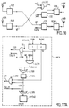
- FIG. 3 illustrates the general structure of a network interface for a station.
- the RE block designates the standardized connection to the IEEE 802 standard, which allows connection to a network output from a computer.
- This connection is for example made with the i82586 integrated circuit sold by INTEL Corporation.
- the RL block is a "local router" whose role will be explained later. Its function is to establish messages to be transmitted, with transmission requests, as well as to collect the messages properly received, and possibly re-direct them.
- ARC block which is the unit of transmission-reception management, depending in particular on collisions.
- An ADF block is added to it, which will allow to correct frequency drifts, by sending artificial messages, when necessary.
- a main channel at the top which is established between a transmit-receive antenna A0, a modulated radio transceiver, for transmission of data, denoted RD, and a circuit CC which has the function, at the transmission, to enhance the corrective code message, and, upon receipt, check the correction of these codes to detect possible errors inside a message (otherwise received normally, i.e. without collision).
- a first lateral channel equipped with an A1 transceiver antenna, a transceiver R1 with fast transmission / reception switching, and RC circuit for radio collision detection.
- GA block which operates as a generator. pseudo-random codes, such codes being used for different purposes according to the invention, on the one hand by the circuit RC, on the other hand by the ARC block already mentioned. RC blocks and ARC are directly interconnected.
- a second channel is represented side with its antenna A2, its receiver R2, and a circuit RP, which allows radio detection of "hidden carriers”.
- the ARC block can be broken down into three ARCA blocks, ARCB and ARCC, as illustrated in Figure 3A.
- the ARCA block is responsible for directing and detecting collisions exploit the result.
- the ARCB block is used for the resolution of collisions, and the establishment of confirmatory orders transmitting or receiving data. It will be incorporated to this ARCB block a collision resolution mechanism which can be of any known type.
- the ARCC block will in charge, in conjunction with the ADF block, of ensuring transmission artificial messages.
- FIG. 4A illustrates the conventional format of an ETHERNET message conforms to the IEEE 802.3 standard.
- the present invention provides that this message is completed, if we wish, by the additional indications which appear right in Figure 4B. They include share an indication of relay recipient and relay source, a code called LARA code (this denomination "LARA" being assigned to the new protocol according to the present invention), and a buffer area that can hold information complementary.
- LARA code this denomination "LARA” being assigned to the new protocol according to the present invention
- the buffer zone contains, as shown in Figure 4C, first a code indicating that it is a point-to-point transmission, that is to say from a single transmitting station to a single station recipient, on the other hand an area indicating the number of jumps already made by the frame in the various relays that she suffered from the original transmitter station. This stamp is updated at each jump or relay in the frame.
- a message can be sent by a post to destination of several posts, what will be called a "diffusion".
- the buffer zone is multiplied, to include a code indicating that it is a broadcast, the number of relays, as well as the recipient addresses of different relays 1 to n, one broadcast message number, and hop count performed by the frame in its previous relays.
- each frame is made up two parts, namely the header, and the body of the package.
- the header contains at least the address of the recipient (s), and the address of the sender, as well as some specific traffic information (e.g. whether or not an acknowledgment is required).
- the body of the packet contains the data to be transmitted (file, accused of reception), as well as the end of packet signals.
- These frames or packets are routed one by one from the block RE of FIG. 3.
- the block RL will process these packets, basically in the event that a recipient is not in the radio range of the transmitter; he then proceeds to a modification of the header by adding the address of an intermediate station, as illustrated in FIG. 4B.
- the packets are then taken care of by the ARC block, which decides on emissions, and interrupts them in the event of a collision detected.
- the CC encoder and the RD device are responsible for the actual emission of the frames in ether. When a frame was correctly transmitted without collision, a signal is transmitted to the RE block, to allow taking the next package.
- the block CC will check the correction of received packets; of reference, packets with error will simply be destroyed.
- the RL block determines if the message has arrived at its destination, or if he is in the process of correspondence or relay. A message arrived at destination is transmitted to the RE block, while that a message to be relayed possibly has its header modified taking into account the relay, to return to the ARC block with a view to a reissue.
- the international standard ISO - IEEE 802 provides for a division layered communication functions. Functions located from the antennas to the included ADF block constitute adaptation of radio functions conventionally called "Medium Access Control" layer or MAC. According to the present invention, a new layer is introduced next, which corresponds to block RL, and which one can call layer “membership and routing” or MR. At the RE block, we find the interface layer Classic ETHERNET.
- the aim is to ensure maximum electromagnetic protection to the digital sequence which must pass between a transmitter and receiver; you have to fight the most effectively against parasitic phenomena or multiple paths. On the other hand, it is useless to fight against interference by possible emissions from others network stations, because this is the criterion that will allow to establish the existence of a collision, and then to resolve this one.
- the RD block can work by spread spectrum with a unique code for all stations of the same network, this unique code can be a pseudo-random code common to all stations, and detected by filter adapted to the reception. This is just one example.
- a radio reception will be considered as demodulable if its gain on reception is greater than or equal to a threshold value e d . If the gain is lower, the received signal is considered “received with errors".
- a value E d is defined, which corresponds to reception "in the immediate vicinity” (This is used in particular for routing, described below). This definition of a threshold common to all stations or stations assumes that the reception power is the same for all, which is generally accepted here.
- the function of the DC circuit, in transmission mode, is to transform IEEE 802 standard frames in binary sequences more resistant to transmission errors, thanks in particular to using error correcting codes (e.g. a interlacing, associated with the use of a convolutional code).
- error correcting codes e.g. a interlacing, associated with the use of a convolutional code
- the component renders the initial frame in correcting any transmission errors on the binary sequence received from the radio reception device data (when the latter has demodulable reception).
- This or these codings can be completed with a technique interleaving where, after coding, we modify substantial bit order in each bit sequence sent; so a brief disturbance only affects bits of information that were far apart from each other others in the original sequence. Normal order is fine safe restored after receipt before decoding error corrector.
- CC block there is provided, upstream of its encoder part, a basic device for rapid detection of errors, like staking the frame with parity bits in sufficient quantities.
- error checking parity checking for example
- FIG. 5 for the description, in the form of a method, of the implementation of the invention.
- step 500 marks the wait for the start of a transmission (transmission) or reception.
- step 501 tests whether it is a broadcast or reception.
- step 510 detailed in Figure 6
- step 550 detailed in FIG. 7.
- listening step 530 active if it was at the start of a broadcast, and at contrary to step 570 of passive listening if it were of a reception.
- steps 530 and 570 are detailed respectively in FIGS. 9 and 8.
- listening passive is performed in both cases.
- the station was at the start of transmission.
- the stage 541 determines the presence or absence of a collision. In the presence of a collision, the transmission is interrupted, preferably after inserting a sequence with an error of parity, on special order addressed to the CC block, as shown in step 542. In the absence of a collision, the emission continues as shown in step 543.
- the block CC searches for a possible parity (or other) error in the incoming frame, and this for a fixed period.
- sub-step 553 we pass the COLL12 signal at 1 if such an error is detected.
- step 510 More complex, the detail of step 510 will now be described with reference to Figure 6.
- the pseudo-random generator GA (figure 3) provided a word pseudo-random Gc with Nc bits.
- step 511 a processing index i is initialized to 1, while the variable COLL11 is set to the value 0, representative "false" collision.
- Step 512 consists in taking from the word g c its ith bit, which will be designated by a.
- Step 513 tests whether the bit a is 0 or 1. If it is 1, step 515 consists in transmitting on the first side channel for a time L c . If it is 0, we will on the contrary go to step 514 to listen on the first side channel for the time L c .
- step 516 it is tested whether a gain carrier greater than a threshold value e c has been detected. If yes, it is because another station has transmitted at the same time (on the basis of a different pseudo-random word). In this case, step 517 consists in passing the variable COLL11 to 1.
- step 519 increments the work index i, and we return to 512.
- the final exit is to go to the next step of collision report, which is step 520 in Figure 5.
- the carrier detection of step 516 does not take place immediately from the start of the listening time interval defined in step 514.
- a time l c is preferably expected, so that the detector collisions cannot be abused by the echo of its own broadcasts.
- step 515 is arranged for the transmission of step 515 to appear continuously, when two consecutive bits of the pseudo-random word g c are at one.
- the second stage follows the first, after a silence. This silence is preferably at least equal to L c . In all, the second stage therefore begins (NOT vs +1) * L vs time units after the start of activation of the collision detector automaton.
- this automaton presents at least two states, namely an emission state to signal or "broadcast" the collision and a listening state. He preferably has three states, the listening state can be a listening passive or active listening.
- the global steps 522, respectively 562, of FIG. 5 consist in transmitting on the first side channel a predetermined signal, such as a pure carrier, for J c time units.
- the passive listening of the global step 570 is detailed in FIG. 8: the sub-step 571 consists in listening on the first side channel for J c time units: the sub-step 572 searches on this channel for a carrier having a gain greater than E c , for a substantial duration, at least equal to L c ; if such a carrier is detected during the time thus defined, step 573 validates a collision variable COLL22 at 1.
- each station defines its own (irregular) transmission / reception comb.
- L c is the clock used to define this comb.
- L c must be chosen greater than the time during which we receive echoes after transmission (fading).
- J c is a time (in principle predetermined), chosen sufficient so that, in the presence of a collision, all the stations concerned can be aware of it.
- Steps 531 to 533 thereof are identical to steps 571 to 573 of FIG. 8.
- Active listening simply consists in adding, in the presence of a collision detected in step 533, a step 534 which modulates a carrier signal on the first lateral channel R1, and this, for at least J c units of time, for report a collision.
- FIG. 6A illustrates by way of example a hardware embodiment of what corresponds to step 510 of FIG. 5.
- the antenna A1 and the receiver R1 of FIG. 3 are here broken down into a transmission part A1E, R1E and a reception part A1R, R1R.
- the GA block has constructed a pseudo-random word g c . This word can be stored in a register RC60, receiving clock pulses which define the processing index i.
- the signal S11 is true and the signal S21 false.
- signal S21 is true, in the event of a collision already detected locally, and the transmitter R1E is energized via the OR gate RC625. If he's false, after complementation by the RC630 inverter, we monitors the output of the R1R receiver, via an AND RC635 gate, which determines a collision condition COLL21, stored in RC639 memory, and corresponding to listening (passive, on this figure 6A).
- FIGS. 6B and 6C illustrate a variant where we have split the first side channel into two "first" channels separate sides, suffixed 1 and 2 respectively in their transmission and reception parts. This results in simplifications of circuits.
- FIG. 6B relates to the first step of the PLC, in the case of a station having transmitted.
- the figure 6C concerns the second stage of the automaton, where we have distinguished (simply for illustration) the case S21 of stations which have already recognized the collision, and that S22 of stations that have not yet recognized it.
- the elements of two channels RC635,645 then RC 639,649 are the same.
- an OR function RC660 combines the COLL21 and COLL22 outputs into COLL2.
- the operation is as follows: The two stages S1 and S2 can take place simultaneously: you can listen to R1R2 during the first step, which takes place as before with R1E1 and R1R1 for an active station. Any collision detected forces immediate emission to R1E2.
- the antenna A2 and the radio stage R2 are subdivided into A2E transmission parts, R2E and receiving parts A2R, R2R.
- A2E transmission parts R2E and receiving parts A2R, R2R.
- reception part A0E and RDE we separate its reception part A0E and RDE, and its A0R and RDR transmission part.
- CCE CCE transmission part and its CCR reception part.
- the CCR coder On reception, the CCR coder provides on the one hand data, on the other hand an indication RE that it is receiving (demodulable signals by the RDR stage).
- the RE signal forces the emission of a busy signal by the R2E stage of the second lateral channel, signifying that the ether is occupied, and this for all stations within radio range.
- An ET LL200 logic function receives the transmission order from base TR, and the signal BT complemented (the complementation is manifested by a small circle on the door entrance LL100).
- the basic transmission order TR therefore does not become an order confirmation of TRE transmission only if no busy signal BT is not received. If TRE is true, the RDE transmitter stage is authorized to send packets or data frames, whether receives after suitable transformation from the encoder circuit CCE emission.
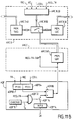
- FIG. 11A describes the ARCA part of the ARC block in Figure 3.
- An ARCA10 sequencer defines steps 1 and 2, depending for example a DEB start logic signal and a signal TR / RE logic indicating whether it is a broadcast or a reception.
- an ET LL310 door intervenes. It has an input receiving the representative RE signal reception, an input receiving the signal S1 and a third input receiving, complemented, the signal REOK. Receiving an incorrect frame will establish a signal COLL12 detected collision logic, representative of a collision on reception, attributable to other stations.
- the device managing the transmissions / receptions pseudo-random alternations on the first side channel can be deleted.
- FIG. 11B illustrates in simplified form the functions of collision resolution.
- ARCB 20 PLC which operates according to a known collision resolution method, such as BEB ("Binary Exponential Backoff" or Exponential Shift binary).
- BEB Binary Exponential Backoff
- Exponential Shift binary Exponential Shift binary
- it can be one of the methods recently introduced to achieve collision resolution deterministic, that is to say in limited time.
- this is the collision resolution process described in the aforementioned Patent Application.
- the switch ARCB50 in Figure 11B also receives signals from an additional ARCC60 memory, which contains artificial messages to which we will return later. he naturally associated with it is a request signal from additional transmission REQ_TR_SUP.
- the Applicant therefore considered it desirable, when the insufficient radio traffic to ensure sufficient time brief synchronization of receptions on broadcasts, artificially increase this traffic by artificial messages.
- the Claimant considered that it had to ensure an appropriate statistical balance of transmission-reception : in other words, the sum of the natural and artificial traffic flows equals one quantity established in advance. But it also has to be property is checked in each of the cells (areas of range) surrounding each station or station. The skilled person will then understand that the theoretical resolution of this problem involves calculations of enormous complexity, that it is excluded to implement in real time and in situ without compromising seriously the functioning of the network.
- the ADF block is responsible for determining how to generate the transmission of artificial messages.
- This ADF block (FIG. 11B) is articulated on an ADF70 chronometric circuit, which defines instants of control with a periodicity T A (step 700, fig.12). For example, pulses of period T A are applied to an AND function ADF72, which also receives the local transmission request signal, complemented, REQ_TR / (the final slash marks a complemented signal). If, at time T A , there is no local transmission request (test 702), then we will close the switch ADF76 to authorize an ADF74 register to supply a pseudo-random number NPA, which will have been obtained (704) from the generator GA of FIG. 3. This pseudo-random number is applied to the negative input of a digital comparator ADF88.
- the set of blocks ADF82 and ADF84 maintains a probability quantity p (t).
- the quantity p (t) is transmitted at the positive input of the digital comparator ADF88. Yes the comparator indicates (test 706) that g (t) is less than p (t), then we will produce the additional transmission request REQ_TR_SUP, to request the transmission of artificial messages (708).
- the quantity p (t) is defined repeatedly from its previous value and observing a change channel status.
- the first function of the block RL is therefore to examine the recipient address contained in the header of Figure 4A.
- the RL block then consults its local routing table. If necessary, it will modify the header of the frame, so that it is transmitted at an intermediate station that is within radio range.
- the format of the packet or frame is then that of FIG. 4B.
- the complete frame is sent to the ARC block, to process the broadcast, resolving any collisions.
- the block ARC On reception, when a frame is received without error, the block ARC transmits it to the RL block, which first determines whether the transit or relay address contained in the header is well that of his local station. If this condition is not checked, the frame can be skipped.
- the transit recipient is the same as the recipient real, it is a frame arrived at destination, and this one is directly transmitted to the RE block, after correction of its header to switch from the format of FIG. 4B to the format of Figure 4A.
- the router will act exactly as if the frame had been obtained from the RE connection, with transmission request : it consults its local routing table, and modifies new frame header, to write a new one intermediate station, or the final recipient, after whereby the frame is returned to the ARC block. It is possible that a copy be submitted to the RE block for information.
- This update day can be driven from normally received frames of the ARC block.
- Each frame normally received includes an indication of its immediate transmitter. It is therefore possible for the RL block to maintain permanently a table of neighboring posts or stations that he receives. In addition, at regular intervals, the RL block will create a spontaneous frame, by which it diffuses to other stations within its radio range at least part of the contents of its routing table (stations it receives). This spontaneous weft can be incorporated into artificial traffic when created. It can be created by authority when there is no need for artificial traffic.
- the stations which are in the two registers are in relation to "symmetrical range" with this post. Routing can only take place using stations checking this symmetrical range condition.
- each extension A can communicate directly (1 transmission) with its "symmetrical range” counterparts, indirectly (2 transmissions) with other stations at "symmetrical range” of the first, which serve as relays, And so on. It is conceivable to set a limit on number of relay stations admitted, which will be called below "number of jumps".
- topological directory for each station.
- This directory is a rectangular matrix or two entries with for example in columns the station numbers registered in the emission register of A, i.e. who receive the current position directly, and on the ordinates numbers of all stations that are accessible from of the current position. Each cell of this table will contain the number of hops required to reach the station ultimately aimed.
- the message format buffer in Figure 4B includes at least a code at the base indicating that it is point-to-point transmission, that is to say interesting only an initial transmitting station and a station final receiver, with the expected number of jumps to go from one to the other.
- each station transmits at intervals its routing table, which allows verification the consistency of the different routing tables of the different stations.
- the broadcasting table collects the station numbers at symmetrical scope, or a subset of these (this subset having to verify the property that it still exists a station in the broadcast table that allows to reach any of the stations on the network, or any stations targeted by the broadcast).
- the broadcasts directory stores the numbers of dissemination of a number of the latest communications in broadcast that have reached the local station.
- the Applicant considers that it is then advantageous to use the format of Figure 4D, where the buffer includes a code distribution, a number of targeted relays, different recipients, a broadcast number and a number of eligible hops.
- the invention can be modified in different ways.
- a side channel can be used to detect collisions, for example as described above in reference to the busy signal, but without using the collision reporting through a side channel.
- the use of the busy signal can be done without use collision reporting by a side channel.
Abstract
Chaque poste de traitement de données est muni d'une interface-réseau (RE), coopérant avec un dispositif de gestion d'émission/réception (ARC) donnant des ordres confirmatifs d'émission ou de réception. L'interface-réseau (Ia,Ib) comprend une unité de routage (RL) apte, d'une part, à déduire, de certains au moins des messages reçus, le ou les postes du réseau qui sont à portée symétrique, un premier poste étant à portée symétrique d'un second poste lorsque lesdits premier et second postes échangent des messages sans l'intermédiaire d'un troisième poste, et d'autre part, à déterminer si un message reçu est destiné ou non au poste local, et à ordonner la réémission dudit message reçu, avec modification éventuelle, si il n'est pas destiné audit poste local ou si il est adressé au poste local ainsi qu'à au moins un autre poste du réseau, ledit poste local servant de poste relais. <IMAGE>Each data processing station is provided with a network interface (RE), cooperating with a transmission / reception management device (ARC) giving confirming transmission or reception orders. The network interface (Ia, Ib) comprises a routing unit (RL) able, on the one hand, to deduce, from at least some of the messages received, the network station or stations which are within symmetrical range, a first station being within symmetrical range of a second station when said first and second stations exchange messages without the intermediary of a third station, and on the other hand, to determine whether or not a received message is intended for the local station, and to order the retransmission of said message received, with possible modification, if it is not intended for said local station or if it is addressed to the local station as well as to at least one other station of the network, said local station serving as relay station. <IMAGE>
Description
L'invention concerne les réseaux informatiques qui permettent l'échange d'informations ou "données" entre différents postes.The invention relates to computer networks which allow exchange of information or "data" between different posts.
Un tel réseau comprend classiquement un milieu de transmission, généralement un câble électrique ou à fibres optiques. En différents endroits de ce câble sont raccordés des stations ou postes, ce raccordement s'effectuant à travers une "interface-réseau".Such a network conventionally comprises a transmission medium, usually an electrical or fiber optic cable. In different places of this cable are connected stations or stations, this connection being made through a "network interface".
Il est nécessaire que les postes se comprennent, malgré leur multiplicité. Dans certains réseaux informatiques, on fixe à cet effet une règle (multiplexage, jeton) selon laquelle au plus l'un des postes peut émettre sur le milieu de communication à un moment donné. Une autre technique autorise un "accès aléatoire" au réseau, c'est à dire que plusieurs postes peuvent émettre en même temps. Une conséquence de cet accès multiple est que des "collisions" peuvent se produire, et il faudra alors les résoudre.It is necessary that the posts understand each other, despite their multiplicity. In some computer networks, we set this effect a rule (multiplexing, token) according to which plus one of the stations can transmit on the communication medium at one point. Another technique allows a "random access" to the network, that is to say that several extensions can send at the same time. A consequence of this multiple access is that "collisions" can occur, and then they will have to be resolved.
Le réseau ETHERNET (marque déposée), régi par la norme dite IEEE 802.3, est du type à accès aléatoire. Le protocole de gestion du réseau est du type à accès multiple sensible à la porteuse avec détection de collision, ou CSMA/CD (Carrier Sense Multiple Access with Collision Detection).The ETHERNET network (registered trademark), governed by the so-called standard IEEE 802.3, is of the random access type. The protocol network management is of the multiple access type sensitive to carrier with collision detection, or CSMA / CD (Carrier Sense Multiple Access with Collision Detection).
La mise en oeuvre d'un tel réseau, mais avec pour milieu de communication l'éther, c'est-à-dire avec transmission par ondes radio, pose différents problèmes que la présente invention vient aider à résoudre.The implementation of such a network, but with the medium of ether communication, i.e. with transmission by radio waves, poses different problems than the present invention comes to help solve.
L'invention vise à tenir compte des particularités des transmissions par radio, qui font que plusieurs trajets existent, sur un ensemble de trois postes non alignés, mais que des obstacles peuvent interdire certains de ces trajets. The invention aims to take into account the peculiarities of radio transmissions, which cause multiple routes to exist, on a set of three non-aligned positions, but that obstacles may prevent some of these journeys.
L'invention a en complément pour but de permettre une transmission indirecte d'informations entre deux postes, via un ou plusieurs postes intermédiaires.The invention further aims to allow transmission indirect information between two stations, via one or several intermediate positions.
L'installation de transmission de données ici proposée est du type comprenant au moins deux postes de traitement de données (le mot "traitement" étant pris à son sens le plus élémentaire). Chaque poste est muni d'une interface-réseau, capable de transmettre des messages sur requête, et de recueillir des messages reçus. Ceci comprend un dispositif de gestion d'émission-réception radio de messages, suivant un protocole choisi.The data transmission installation proposed here is from type comprising at least two data processing stations (the word "treatment" being taken in its most basic sense). Each station is equipped with a network interface, capable of transmit messages on request, and collect messages received. This includes a management device radio transmission-reception of messages, according to a protocol selected.
Selon un aspect de l'invention, l'interface-réseau comprend une unité de routage apte, d'une part, à déduire, de certains au moins des messages reçus, le ou les postes du réseau qui sont à portée symétrique, un premier poste étant à portée symétrique d'un second poste lorsque lesdits premier et second postes échangent des messages sans l'intermédiaire d'un troisième poste, et d'autre part, à déterminer si un message reçu est destiné ou non au poste local, et à ordonner la réémission dudit message reçu, avec modification éventuelle, s'il n'est pas destiné audit poste local ou s'il est adressé au poste local ainsi qu'à au moins un autre poste du réseau, ledit poste local servant de poste relais.According to one aspect of the invention, the network interface comprises a routing unit capable, on the one hand, of deducing, from certain at least of the messages received, the network extension (s) which are within symmetrical range, a first station being within range symmetrical of a second station when said first and second posts exchange messages without the intermediary a third station, and secondly, to determine if a message received is intended or not for the local station, and to order re-transmission of said received message, with possible modification, if it is not intended for said local station or if it is addressed to the local extension as well as at least one other extension of the network, said local station serving as relay station.
Avantageusement, chaque interface-réseau comprend une mémoire propre à mémoriser au moins une liste des postes qu'elle reçoit et une liste des postes qui la reçoive.Advantageously, each network interface includes a memory suitable for memorizing at least a list of the positions it receives and a list of positions that receives it.
D'autres caractéristiques et avantages de l'invention apparaítront à l'examen de la description détaillée ci-après, et des dessins annexés, sur lesquels :
- la figure 1 est un schéma très simplifié d'un réseau informatique classique où le milieu de transmission est filaire;
- la figure 2 est un schéma très simplifié illustrant quatre stations interconnectées par une transmission radio;
- la figure 3 est le schéma de principe de l'ensemble de l'interface-réseau, pour un poste selon l'invention;
- la figure 3A est un détail partiel de la figure 3;
- les figures 4A à 4D illustrent le format des trames;
- la figure 5 est un schéma fonctionnel d'un mécanisme applicable à la détection de collisions;
- la figure 6 est un schéma fonctionnel plus détaillé d'une partie de la figure 5, tandis que la figure 6A est un schéma électrique équivalent, correspondant à la figure 6 et les figures 6B et 6C en montrent une variante;
- les figures 7, 8 et 9 sont d'autres schémas fonctionnels plus détaillés, relatifs à des parties du mécanisme de la figure 5;
- la figure 10 est un schéma électrique des opérations effectuées au niveau du second canal latéral;
- la figure 11A est un schéma électrique équivalent des opérations de l'automate détecteur de collisions, tandis que la figure 11B est un schéma électrique équivalent des autres parties du dispositif de gestion d'émission/réception d'un poste;
- les figures 12 et 13 sont des mécanismes permettant, par la transmission de messages artificiels, d'effectuer la synchronisation fréquentielle entre les différents postes.
- Figure 1 is a very simplified diagram of a conventional computer network where the transmission medium is wired;
- FIG. 2 is a very simplified diagram illustrating four stations interconnected by radio transmission;
- Figure 3 is the block diagram of the entire network interface, for a station according to the invention;
- Figure 3A is a partial detail of Figure 3;
- FIGS. 4A to 4D illustrate the format of the frames;
- FIG. 5 is a functional diagram of a mechanism applicable to the detection of collisions;
- Figure 6 is a more detailed block diagram of part of Figure 5, while Figure 6A is an equivalent electrical diagram, corresponding to Figure 6 and Figures 6B and 6C show a variant;
- Figures 7, 8 and 9 are other more detailed block diagrams relating to parts of the mechanism of Figure 5;
- FIG. 10 is an electrical diagram of the operations carried out at the level of the second lateral channel;
- FIG. 11A is an equivalent electrical diagram of the operations of the collision detection automaton, while FIG. 11B is an equivalent electrical diagram of the other parts of the transmission / reception management device of a station;
- FIGS. 12 and 13 are mechanisms allowing, by the transmission of artificial messages, to carry out frequency synchronization between the different stations.
Les dessins annexés sont, pour l'essentiel, de caractère certain. En conséquence, ils font partie intégrante de la description et pourront non seulement servir à compléter celle-ci, mais aussi contribuer à la définition de l'invention le cas échéant. The attached drawings are essentially of a character certain. Consequently, they are an integral part of the description and can not only be used to complete this, but also contribute to the definition of the invention if applicable.
Par ailleurs, le Demandeur dépose ce jour une autre demande de brevet intitulée "Dispositif de transmission de données pour réseau à accès aléatoire, avec résolution de collision perfectionnée, et procédé correspondant". Du fait de relations techniques existant avec la présente Demande, la description et les dessins de cette autre Demande sont également incorporables à la présente description.In addition, the Applicant files another request today document entitled "Data transmission device for random access networks, with collision resolution improved, and corresponding process. "Because of relationships existing techniques with this Application, the description and drawings of this other Application are also incorporated into this description.
Sur la figure 1, un milieu de transmission MT est relié à des interfaces-réseaux Ia à Ic, respectivement connectés à des postes Pa à Pc. C'est là la structure classique d'un réseau informatique de transmission de données, auquel peut s'appliquer le protocole CSMA/CD déjà évoqué, conformément à la norme IEEE 802.3.In Figure 1, an MV transmission medium is connected to network interfaces Ia to Ic, respectively connected to Pa to Pc positions. This is the classic structure of a network data transmission computing, to which may apply the CSMA / CD protocol already mentioned, in accordance with IEEE 802.3 standard.
Le spécialiste sait que les modèles de définition de telles interfaces sont définies "en couches" (norme ISO), à chacune desquelles est affectée une fonction précise. Ce découpage en couches fonctionnelles permet d'assurer la compatibilité d'organes du réseau de sources différentes, lorsqu'ils se trouvent interconnectés. Il sera fait référence dans la suite à cette notion de couche. On distinguera d'ailleurs les couches du protocole proprement dites, et les couches supérieures du protocole.The specialist knows that the models for defining such interfaces are defined "in layers" (ISO standard), each which are assigned a specific function. This division into functional layers ensures compatibility network organs from different sources, when find interconnected. Reference will be made later to this notion of layer. We will also distinguish the layers of the protocol itself, and the upper layers of the protocol.
Les postes tels que Pa sont des postes de traitement de données (le mot traitement est utilisé ici au sens le plus élémentaire, ce traitement pouvant être très simple). Tous les traitements effectués dans le poste sont extérieurs à la transmission de données proprement dite. Mais il pourra exister dans le poste des opérations spécifiques tenant compte spécifiquement de la nature et de certaines conditions applicables à la transmission de données. Ce sont là les couches supérieures du protocole.Posts such as Pa are data processing stations (the word treatment is used here in the most basic sense, this treatment can be very simple). All treatments performed in the post are external to the data transmission proper. But there may be in the specific operations item taking into account specifically of the nature and certain applicable conditions data transmission. These are the layers of the protocol.
Les couches du protocole lui-même vont au contraire régir la transmission de données en ses conditions de base, d'une façon qui permette d'en assurer la sécurité. The layers of the protocol itself will, on the contrary, govern the transmission of data in its basic conditions, of a in a way that ensures security.
Sur la figure 2, les postes ou stations Pa à Pd sont maintenant reliées à des dispositifs radio Ra à Rd, munis d'antennes. Dans l'exemple simplifié illustré, toutes les stations peuvent échanger directement des données, sauf les stations Rb et Rd, entre lesquelles existe un obstacle OBS.In FIG. 2, the stations or stations Pa to Pd are now connected to radio devices Ra to Rd, provided with antennas. In the simplified example illustrated, all the stations can exchange data directly, except stations Rb and Rd, between which there is an OBS obstacle.
Ce que l'on appelle ici interface-réseau, dans une acception plus large que pour les réseaux informatiques à câble, c'est tout ce qui se trouve entre le poste proprement dit et la ou les antennes qu'il comporte.What is called here network-interface, in an acceptation wider than for wired computer networks, it's everything between the station itself and the the antennas it contains.
Le mot "message" désigne ici un ensemble de données à transmettre, de taille quelconque. Le mot "trame" ou "paquet" désigne l'unité élémentaire de transmission de données, c'est à dire le bloc de données que l'on peut transmettre ensemble.The word "message" here designates a set of data to transmit, of any size. The word "weft" or "package" indicates the elementary unit of data transmission, it is ie the block of data that can be transmitted together.
L'une des particularités de la présente invention est de faire en sorte que lorsqu'un poste désire émettre une trame, ce poste soit le seul à le faire dans son domaine de portée radio.One of the features of the present invention is to ensure that when a station wishes to transmit a frame, this position be the only one to do so in its scope radio.
Il est maintenant fait référence à la figure 3, qui illustre la structure générale d'une interface-réseau pour un poste.Reference is now made to FIG. 3, which illustrates the general structure of a network interface for a station.
A droite, le bloc RE désigne le raccordement normalisé à la
norme IEEE 802, qui permet la liaison avec une sortie réseau
d'un ordinateur. Ce raccord est par exemple réalisé avec le
circuit intégré i82586 vendu par INTEL Corporation.On the right, the RE block designates the standardized connection to the
A sa gauche, le bloc RL est un "routeur local" dont le rôle sera précisé plus loin. Il a pour fonction d'établir des messages à transmettre, avec des requêtes de transmission, ainsi que de recueillir les messages convenablement reçus, et éventuellement de les re-diriger.To its left, the RL block is a "local router" whose role will be explained later. Its function is to establish messages to be transmitted, with transmission requests, as well as to collect the messages properly received, and possibly re-direct them.
Encore à gauche apparaít un bloc ARC, qui est l'unité de gestion d'émission-réception, en fonction notamment des collisions. Still on the left appears an ARC block, which is the unit of transmission-reception management, depending in particular on collisions.
Il lui est adjoint un bloc ADF, qui va permettre de corriger des dérives en fréquence, par l'émission de messages artificiels, lorsque cela est nécessaire.An ADF block is added to it, which will allow to correct frequency drifts, by sending artificial messages, when necessary.
A gauche du bloc ARC, on trouve en haut un canal principal, qui s'établit entre une antenne d'émission-réception A0, un émetteur-récepteur radio modulé, pour la transmission de données, noté RD, et un circuit CC qui a pour fonction, à l'émission, d'agrémenter le message de codes correcteurs, et, à la réception, de vérifier la correction de ces codes pour détecter d'éventuelles erreurs à l'intérieur d'un message (reçu par ailleurs normalement, c'est-à-dire sans collision).To the left of the ARC block, there is a main channel at the top, which is established between a transmit-receive antenna A0, a modulated radio transceiver, for transmission of data, denoted RD, and a circuit CC which has the function, at the transmission, to enhance the corrective code message, and, upon receipt, check the correction of these codes to detect possible errors inside a message (otherwise received normally, i.e. without collision).
A gauche et au milieu se trouve un premier canal latéral, muni d'une antenne d'émission-réception A1, d'un émetteur-récepteur R1 à commutation émission/réception rapide, et d'un circuit RC pour la détection radio des collisions.On the left and in the middle is a first lateral channel, equipped with an A1 transceiver antenna, a transceiver R1 with fast transmission / reception switching, and RC circuit for radio collision detection.
Il s'y trouve aussi un bloc GA qui opère en tant que générateur de codes pseudo-aléatoires, de tels codes étant utilisés à différentes fins selon l'invention, d'une part par le circuit RC, d'autre part par le bloc ARC déjà cité. Les blocs RC et ARC sont directement interconnectés.There is also a GA block which operates as a generator. pseudo-random codes, such codes being used for different purposes according to the invention, on the one hand by the circuit RC, on the other hand by the ARC block already mentioned. RC blocks and ARC are directly interconnected.
Enfin, à gauche et en bas, est représenté un second canal latéral avec son antenne A2, son récepteur R2, et un circuit RP, qui permet la détection radio de "porteuses cachées".Finally, on the left and bottom, a second channel is represented side with its antenna A2, its receiver R2, and a circuit RP, which allows radio detection of "hidden carriers".
Le découpage fonctionnel auquel il a été procédé sur la figure 3 ne sera pas toujours respecté dans la suite, dans le but de faciliter la compréhension.The functional breakdown which was carried out on the Figure 3 will not always be respected in the following, in the aim to facilitate understanding.
Ainsi, le bloc ARC peut être décomposé en trois blocs ARCA, ARCB et ARCC, comme illustré sur la figure 3A. Le bloc ARCA est chargé de diriger la détection de collisions, et d'en exploiter le résultat. Le bloc ARCB est utilisé pour la résolution de collisions, et l'établissement d'ordres confirmatifs d'émission ou de réception de données. Il sera incorporé à ce bloc ARCB un mécanisme de résolution de collisions qui peut être de tout type connu. Enfin, le bloc ARCC va se charger, en liaison avec le bloc ADF, d'assurer la transmission des messages artificiels.Thus, the ARC block can be broken down into three ARCA blocks, ARCB and ARCC, as illustrated in Figure 3A. The ARCA block is responsible for directing and detecting collisions exploit the result. The ARCB block is used for the resolution of collisions, and the establishment of confirmatory orders transmitting or receiving data. It will be incorporated to this ARCB block a collision resolution mechanism which can be of any known type. Finally, the ARCC block will in charge, in conjunction with the ADF block, of ensuring transmission artificial messages.
Il est maintenant fait référence à la figure 4.Reference is now made to FIG. 4.
La figure 4A illustre le format classique d'un message ETHERNET conforme à la norme IEEE 802.3.FIG. 4A illustrates the conventional format of an ETHERNET message conforms to the IEEE 802.3 standard.
La présente invention prévoit que ce message est complété, si on le souhaite, par les indications supplémentaires qui apparaissent à droite sur la figure 4B. Elles comprennent d'une part une indication de destinataire relais et de source relais, un code dit code LARA (cette dénomination "LARA" étant attribuée au protocole nouveau selon la présente invention), et une zone de tampon qui peut contenir des informations complémentaires.The present invention provides that this message is completed, if we wish, by the additional indications which appear right in Figure 4B. They include share an indication of relay recipient and relay source, a code called LARA code (this denomination "LARA" being assigned to the new protocol according to the present invention), and a buffer area that can hold information complementary.
Lorsque plusieurs relais sont prévus, la zone de tampon contient, comme indiqué sur la figure 4C, tout d'abord un code indiquant qu'il s'agit d'une transmission point à point, c'est-à-dire d'un seul poste émetteur à un seul poste destinataire, d'autre part une zone indiquant le nombre de sauts déjà effectués par la trame dans les différents relais qu'elle a subis depuis le poste émetteur initial. Ce tampon est remis à jour à chaque saut ou relais de la trame.When several relays are planned, the buffer zone contains, as shown in Figure 4C, first a code indicating that it is a point-to-point transmission, that is to say from a single transmitting station to a single station recipient, on the other hand an area indicating the number of jumps already made by the frame in the various relays that she suffered from the original transmitter station. This stamp is updated at each jump or relay in the frame.
A l'inverse, un message peut être émis par un poste à
destination de plusieurs postes, ce qu'on appellera une
"diffusion". Dans ce cas, comme illustré sur la figure 4D, la
zone tampon est multipliée, pour comprendre un code indiquant
qu'il s'agit d'une diffusion, le nombre de relais, ainsi que
les adresses-destinataire de différents relais 1 à n, un
numéro de message de diffusion, et le nombre de sauts
effectués par la trame dans ses relais précédents.Conversely, a message can be sent by a post to
destination of several posts, what will be called a
"diffusion". In this case, as illustrated in FIG. 4D, the
buffer zone is multiplied, to include a code indicating
that it is a broadcast, the number of relays, as well as
the recipient addresses of
Ce qui vient d'être décrit est la structure d'une "trame" de messages. Dans un exemple simple, chaque trame est constituée de deux parties, à savoir l'en-tête, et le corps du paquet. What has just been described is the structure of a "frame" of messages. In a simple example, each frame is made up two parts, namely the header, and the body of the package.
L'en-tête contient au minimum l'adresse du ou des destinataires, et l'adresse de l'expéditeur, ainsi que quelques informations spécifiques au sujet du trafic (par exemple nécessité ou non d'un accusé de réception). Le corps du paquet contient les données à transmettre (fichier, accusé de réception), ainsi que les signaux de fin de paquets.The header contains at least the address of the recipient (s), and the address of the sender, as well as some specific traffic information (e.g. whether or not an acknowledgment is required). The body of the packet contains the data to be transmitted (file, accused of reception), as well as the end of packet signals.
Ces trames ou paquets sont acheminés un par un à partir du bloc RE de la figure 3. Le bloc RL va traiter ces paquets, essentiellement dans le cas où un destinataire ne serait pas dans la zone de portée radio de l'émetteur; il procède alors à une modification de l'en-tête par le rajout de l'adresse d'une station intermédiaire, comme illustré sur la figure 4B. Les paquets sont ensuite pris en charge par le bloc ARC, qui décide des émissions, et les interrompt en cas de collision détectée. Le codeur CC et le dispositif RD se chargent de l'émission effective des trames dans l'éther. Lorsqu'une trame a été correctement transmise sans collision, un signal est transmis jusqu'au bloc RE, pour permettre de prendre le prochain paquet.These frames or packets are routed one by one from the block RE of FIG. 3. The block RL will process these packets, basically in the event that a recipient is not in the radio range of the transmitter; he then proceeds to a modification of the header by adding the address of an intermediate station, as illustrated in FIG. 4B. The packets are then taken care of by the ARC block, which decides on emissions, and interrupts them in the event of a collision detected. The CC encoder and the RD device are responsible for the actual emission of the frames in ether. When a frame was correctly transmitted without collision, a signal is transmitted to the RE block, to allow taking the next package.
A la réception, le fonctionnement se produit en inverse. Le bloc CC va vérifier la correction des paquets reçus ; de rpéférence, les paquets avec erreur seront simplement détruits.On reception, the operation occurs in reverse. The block CC will check the correction of received packets; of reference, packets with error will simply be destroyed.
Le bloc RL détermine si le message est arrivé à sa destination, ou s'il est en cours de correspondance ou de relais. Un message arrivé à destination est transmis au bloc RE, tandis qu'un message à relayer voit éventuellement son en-tête modifiée compte tenu du relais, pour retourner vers le bloc ARC en vue d'une réémission.The RL block determines if the message has arrived at its destination, or if he is in the process of correspondence or relay. A message arrived at destination is transmitted to the RE block, while that a message to be relayed possibly has its header modified taking into account the relay, to return to the ARC block with a view to a reissue.
La norme internationale ISO - IEEE 802 prévoit un découpage
en couches des fonctions de communication. Les fonctions
situées depuis les antennes jusqu'au bloc ADF inclus constituent
une adaptation à la transmission par radio des fonctions
classiquement dénommées couche "Medium Access Control"
ou MAC. Conformément à la présente invention, une nouvelle
couche est introduite ensuite, qui correspond au bloc RL, et
que l'on peut appeler couche "membership and routing" ou MR.
Au niveau du bloc RE, on retrouve la couche d'interface
ETHERNET classique.The international standard ISO -
Il sera maintenant question de la couche dite MAC, qui va être décrite en détail.We will now talk about the so-called MAC layer, which will be described in detail.
Tout d'abord, un procédé précis de transmission de données doit être appliqué au niveau du bloc RD. Il s'agit en effet de transformer une séquence numérique binaire en un signal électromagnétique propre à la propagation radio via l'antenne, et réciproquement, ce qui est généralement plus délicat.First, a precise method of data transmission must be applied at the RD block level. It is indeed to transform a binary digital sequence into a signal electromagnetic suitable for radio propagation via the antenna, and vice versa, which is generally more delicate.
Le but visé est d'assurer un maximum de protection électromagnétique à la séquence numérique qui doit transiter entre un émetteur et un récepteur; il faut notamment lutter le plus efficacement possible contre les phénomènes de parasitage ou de trajets multiples. Par contre, il est inutile de lutter contre le brouillage par les émissions éventuelles des autres postes du réseau, car c'est là le critère qui va permettre d'établir l'existence d'une collision, et ensuite de résoudre celle-ci.The aim is to ensure maximum electromagnetic protection to the digital sequence which must pass between a transmitter and receiver; you have to fight the most effectively against parasitic phenomena or multiple paths. On the other hand, it is useless to fight against interference by possible emissions from others network stations, because this is the criterion that will allow to establish the existence of a collision, and then to resolve this one.
Ainsi, le bloc RD peut travailler par étalement de spectre avec un code unique pour toutes les stations d'un même réseau, ce code unique pouvant être un code pseudo-aléatoire commun à toutes les stations, et détecté par filtre adapté à la réception. Ce n'est là qu'un exemple.So the RD block can work by spread spectrum with a unique code for all stations of the same network, this unique code can be a pseudo-random code common to all stations, and detected by filter adapted to the reception. This is just one example.
On notera d'ailleurs qu'il est nécessaire d'assurer une synchronisation convenable sur le plan fréquentiel entre les différents postes intervenant. L'homme du métier sait assurer cette synchronisation en cas de trafic suffisant. Lorsque cette condition n'est pas vérifiée, la dérive entre les différents oscillateurs-pilotes peut devenir telle que le synchronisme ne peut plus être rattrapé très rapidement. Il sera proposé plus loin une solution à ce problème. Note also that it is necessary to ensure synchronization frequency-appropriate between different positions involved. A person skilled in the art knows how to ensure this synchronization in case of sufficient traffic. When this condition is not verified, the drift between the different pilot oscillators can become such that the synchronism can no longer be caught up very quickly. he a solution to this problem will be proposed later.
De façon générale, une réception radio sera considérée comme démodulable si son gain à la réception est supérieur ou égal à une valeur de seuil ed. Si le gain est inférieur, le signal reçu est considéré comme "reçu avec erreurs". Avantageusement, on définit une valeur Ed, laquelle correspond à une réception "à proximité immédiate" (Ceci sert notamment au routage, décrit plus loin). Cette définition d'un seuil commun à toutes les stations ou postes suppose que la puissance de réception est la même pour tous, ce qui est admis ici de façon générale.Generally, a radio reception will be considered as demodulable if its gain on reception is greater than or equal to a threshold value e d . If the gain is lower, the received signal is considered "received with errors". Advantageously, a value E d is defined, which corresponds to reception "in the immediate vicinity" (This is used in particular for routing, described below). This definition of a threshold common to all stations or stations assumes that the reception power is the same for all, which is generally accepted here.
Le circuit CC a pour fonction, en mode émission, de transformer
les trames à la norme IEEE 802 en des séquences binaires
plus résistantes aux erreurs de transmission, grâce notamment
à l'emploi de codes correcteurs d'erreurs (par exemple un
entrelacement, associé à l'usage d'un code convolutionnel).The function of the DC circuit, in transmission mode, is to transform
En mode réception, le composant restitue la trame initiale en corrigeant les éventuelles erreurs de transmission sur la séquence binaire reçue du dispositif de réception radio des données (lorsque celui-ci dispose d'une réception démodulable).In reception mode, the component renders the initial frame in correcting any transmission errors on the binary sequence received from the radio reception device data (when the latter has demodulable reception).
De plus, il détecte les éventuelles erreurs résiduelles à un traitement de la trame reconstituée, et signale ces erreurs. Il peut en résulter un état de "trame reçue avec erreurs".In addition, it detects any residual errors at a processing of the reconstructed frame, and signals these errors. This can result in a "frame received with errors" state.
De préférence, on utilise deux codages détecteurs et correcteurs d'erreurs:
- l'un pour les erreurs "dispersées" (codage de VITERBI),
- l'autre, traitant les erreurs par blocs (codage de REED-SOLOMON, avec entrelacement).
- one for "scattered" errors (VITERBI coding),
- the other, dealing with block errors (REED-SOLOMON coding, with interleaving).
Ceci suppose la mise en oeuvre desdits codages à la première émission des données (au moins), et la mise en oeuvre de traitements de contrôle à la (ou chaque) réception.This supposes the implementation of said codings at the first data transmission (at least), and the implementation of control processing at (or each) reception.
Ce ou ces codages peuvent être complété d'une technique d'entrelacement où, après codage, on modifie de façon substantielle l'ordre des bits dans chaque séquence de bits envoyés; de la sorte, une perturbation brève ne touche que des bits d'information qui étaient très éloignés les uns des autres dans la séquence originelle. L'ordre normal est bien sûr rétabli après réception avant d'opérer le décodage correcteur d'erreurs.This or these codings can be completed with a technique interleaving where, after coding, we modify substantial bit order in each bit sequence sent; so a brief disturbance only affects bits of information that were far apart from each other others in the original sequence. Normal order is fine safe restored after receipt before decoding error corrector.
Il est également possible d'améliorer encore les choses en tenant compte de données physiques comme le gain instantané de réception par radio, ou bien des considérations statistiques sur les antennes diversifiées ou les trajets de propagations multiples.It is also possible to improve things further by taking into account physical data such as instant gain radio reception, or statistical considerations on diversified antennas or propagation routes multiple.
Dans le bloc CC, il est prévu, en amont de sa partie codeur, un dispositif élémentaire de détection rapide d'erreurs, comme le jalonnement de la trame par des bits de parité en quantités suffisantes. A la réception, l'opération de contrôle d'erreurs (contrôle de parité par exemple) est effectuée en aval de sa partie décodeur.In the CC block, there is provided, upstream of its encoder part, a basic device for rapid detection of errors, like staking the frame with parity bits in sufficient quantities. Upon receipt, the operation of error checking (parity checking for example) is performed downstream of its decoder part.
Il est maintenant fait référence à la figure 5, pour la description, en forme de procédé, de la mise en oeuvre de l'invention.Reference is now made to FIG. 5, for the description, in the form of a method, of the implementation of the invention.
Sur la figure 5, l'étape 500 marque l'attente du début d'une transmission (émission) ou d'une réception.In FIG. 5, step 500 marks the wait for the start of a transmission (transmission) or reception.
Sur un tel début, l'étape 501 teste s'il s'agit d'une émission ou d'une réception.On such a start, step 501 tests whether it is a broadcast or reception.
S'agissant d'une émission, on passe à l'étape 510, détaillée sur la figure 6; s'agissant au contraire d'une réception, on passe à l'étape 550, détaillée sur la figure 7.As for a broadcast, we go to step 510, detailed in Figure 6; contrary to reception, we go to step 550, detailed in FIG. 7.
Dans l'un ou l'autre cas, les étapes suivantes 520 respectivement
560 déterminent si une condition de collision a été
reconnue, ce qui est matérialisé par des signaux logiques
COLL11 et COLL12, respectivement ( 0 = faux; 1 = vrai). In either case, the following
S'il s'agit d'une collision, on passe aux étapes 522 et 562
respectivement.If it is a collision, go to
En l'absence de collision, on passe à l'étape 530 d'écoute
active s'il s'agissait au départ d'une émission, et au
contraire à l'étape 570 d'écoute passive s'il s'agissait
d'une réception. Ces étapes 530 et 570 sont détaillées
respectivement sur les figures 9 et 8. En variante, l'écoute
passive est effectuée dans les deux cas.If there is no collision, we go to listening
Ensuite, on passe aux étapes 540 et 580 respectivement, pour
fixer un état de collision en fonction du résultat de l'étape
précédente.Then we go to
Dans un cas, le poste était en début de transmission. L'étape
541 détermine la présence ou l'absence de collision. En présence
d'une collision, l'émission est interrompue, de préférence
après insertion d'une séquence munie d'une erreur de
parité, sur commande spéciale adressée au bloc CC, comme
figuré à l'étape 542. En l'absence de collision, l'émission
se poursuit comme l'indique l'étape 543.In one case, the station was at the start of transmission. The
Dans l'autre cas, il s'agissait au départ d'une réception. En
l'absence de collision, celle-ci continue à l'étape 585 avec
toutefois un rejet de la trame en cours si elle comporte une
erreur de parité (ou autre).In the other case, it was initially a reception. In
absence of collision, this continues at
Le détail de l'étape 550 est relativement simple, et sera dès
maintenant décrit en référence à la figure 7. Au départ, la
sous-étape 551 établit une condition collision fausse (COLL12
= 0). A l'étape 552, le bloc CC recherche une éventuelle
erreur de parité (ou autre) dans la trame arrivante, et ce
pendant une durée fixée. A la sous-étape 553, on fait passer
le signal COLL12 à 1 si une telle erreur est détectée.The detail of
Plus complexe, le détail de l'étape 510 sera maintenant
décrit en référence à la figure 6. More complex, the detail of
Le générateur pseudo-aléatoire GA (figure 3) a fourni un mot pseudo-aléatoire Gc possédant Nc bits.The pseudo-random generator GA (figure 3) provided a word pseudo-random Gc with Nc bits.
A l'étape 511, on initialise à 1 un indice de traitement i,
tandis que la variable COLL11 est mise à la valeur 0, représentative
de collision "fausse".In
L'étape 512 consiste à prélever dans le mot gc son ième bit, que l'on va désigner par a.Step 512 consists in taking from the word g c its ith bit, which will be designated by a.
L'étape 513 teste si le bit a vaut 0 ou 1. S'il vaut 1, l'étape
515 consiste à émettre sur le premier canal latéral
pendant un temps Lc. S'il vaut 0, on va au contraire à
l'étape 514 écouter sur le premier canal latéral pendant le
temps Lc.Step 513 tests whether the bit a is 0 or 1. If it is 1,
A l'étape 516, on teste si une porteuse de gain supérieure à
une valeur de seuil ec a été détectée. Si oui, c'est qu'une
autre station a émis en même temps (sur la base d'un mot
pseudo-aléatoire différent). Dans ce cas, l'étape 517
consiste à faire passer à 1 la variable COLL11.In
Dans l'un ou l'autre cas, on retourne ensuite au test 518 qui détermine si l'on est arrivé au dernier bit du mot pseudo-aléatoire GC. Si tel n'est pas le cas, l'étape 519 incrémente l'indice de travail i, et l'on retourne en 512.In either case, we then return to test 518 which determines if we have reached the last bit of the pseudo-random word GC. If not, step 519 increments the work index i, and we return to 512.
La sortie finale consiste à passer à l'étape suivante de
signalement de collision, qui est l'étape 520 de la figure 5.The final exit is to go to the next step of
collision report, which is
Avantageusement la détection de porteuse de l'étape 516 ne
s'effectue pas immédiatement dès le début de l'intervalle de
temps d'écoute défini à l'étape 514. On attend de préférence
un temps lc, de sorte que le détecteur de collisions ne
puisse pas être abusé par l'écho de ses propres émissions.Advantageously, the carrier detection of
Par ailleurs, il est fait en sorte que l'émission de l'étape
515 apparaisse de façon continue, lorsque deux bits consécutifs
du mot pseudo-aléatoire gc sont à un. Furthermore, it is arranged for the transmission of
Ce qui vient d'être décrit concerne la première étape du
fonctionnement de l'automate détecteur de collisions, étape
qui peut se faire soit dans un état actif, soit dans un état
passif, suivant le résultat du test 501 de la figure 5.What has just been described concerns the first stage of the
collision detector controller operation, step
which can be done either in an active state or in a state
passive, according to the result of
La seconde étape succède à la première, après un silence. Ce
silence est de préférence au moins égal à Lc. En tout, la
seconde étape commence donc
Pendant la seconde étape, cet automate présente au moins deux états, à savoir un état d'émission pour signaler ou "diffuser" la collision et un état d'écoute. Il possède de préférence trois états, l'état d'écoute pouvant être une écoute passive ou une écoute active.During the second stage, this automaton presents at least two states, namely an emission state to signal or "broadcast" the collision and a listening state. He preferably has three states, the listening state can be a listening passive or active listening.
On considère maintenant deux nouvelles grandeurs de référence qui sont un seuil de niveau Ec au moins égal au seuil ec déjà invoqué. On considère aussi une nouvelle constante temporelle Jc, plus grande que le temps Lc.We now consider two new reference quantities which are a level threshold E c at least equal to the threshold e c already invoked. We also consider a new time constant J c , larger than the time L c .
Lorsqu'une collision a été détectée (COLL11 = 1, respectivement
COLL12 = 1) dans le poste local, les étapes globales
522, respectivement 562, de la figure 5 consistent à émettre
sur le premier canal latéral un signal prédéterminé, tel
qu'une porteuse pure, pendant Jc unités de temps.When a collision has been detected (COLL11 = 1, respectively COLL12 = 1) in the local station, the
L'écoute passive de l'étape globale 570 est détaillée sur la
figure 8: la sous-étape 571 consiste à écouter sur le premier
canal latéral pendant Jc unités de temps : la sous-étape 572
recherche sur ce canal une porteuse possédant un gain supérieur
à Ec, pendant une durée substantielle, au moins égale
à Lc ; si une telle porteuse est détectée pendant le temps
ainsi défini, l'étape 573 valide une variable de collision
COLL22 à 1.The passive listening of the
En quelque sorte, chaque station définit un peigne (irrégulier) d'émission/réception qui lui est propre. Lc est l'horloge utilisée pour définir ce peigne. Lc doit être choisi supérieur au temps pendant lequel on reçoit des échos après émission (fading). Jc est un temps (en principe prédéterminé), choisi suffisant pour que, en présence d'une collision, toutes les stations concernées puissent en avoir connaissance.In a way, each station defines its own (irregular) transmission / reception comb. L c is the clock used to define this comb. L c must be chosen greater than the time during which we receive echoes after transmission (fading). J c is a time (in principle predetermined), chosen sufficient so that, in the presence of a collision, all the stations concerned can be aware of it.
Si le poste était en émission précédemment, mais n'a pas
détecté de collision, il peut faire une écoute passive. De
préférence, il procède à une écoute active, comme indiqué à
l'étape 530 de la figure 5, et détaillé sur la figure 9. Les
étapes 531 à 533 de celle-ci sont identiques aux étapes 571
à 573 de la figure 8.
L'écoute active consiste simplement à ajouter, en présence
d'une collision détectée à l'étape 533, une étape 534 qui
module un signal porteur sur le premier canal latéral R1, et
ce, pendant au moins Jc unités de temps, pour signaler une
collision.If the station was on transmission before, but did not detect a collision, it can make a passive listening. Preferably, it performs active listening, as indicated in
Active listening simply consists in adding, in the presence of a collision detected in
La figure 6A illustre à titre d'exemple une réalisation matérielle de ce qui correspond à l'étape 510 de la figure 5. L'antenne A1 et le récepteur R1 de la figure 3 sont ici décomposés en une partie émission A1E, R1E et une partie réception A1R, R1R. Le bloc GA a construit un mot pseudo-aléatoire gc. Ce mot peut être stocké dans un registre RC60, recevant des impulsions d'horloge qui définissent l'indice de traitement i.FIG. 6A illustrates by way of example a hardware embodiment of what corresponds to step 510 of FIG. 5. The antenna A1 and the receiver R1 of FIG. 3 are here broken down into a transmission part A1E, R1E and a reception part A1R, R1R. The GA block has constructed a pseudo-random word g c . This word can be stored in a register RC60, receiving clock pulses which define the processing index i.
On considère maintenant les deux étapes successives de l'automate de détection de collision, avec l'état actif.We now consider the two successive stages of the collision detection machine, with the active state.
Pendant la première étape, le signal S11 est vrai et le signal S21 faux. Les deux portes ET RC610 et RC615 sont donc validées. Elles reçoivent par ailleurs respectivement le bit courant en sortie du registre RC60 et son complément établi par l'inverseur RC611. Si le bit vaut 1, l'émetteur R1E est excité. Si le bit vaut 0, et après un retard défini par un étage RC616, on surveille la sortie du récepteur R1R, un signal logique COLL11 étant défini par une porte ET RC618. Si on obtient une émission pendant que le bit courant du mot GC est à 1, et après le retard lc déjà mentionné, COLL11 est vrai (COLL11 = 1 en mémoire RC619).During the first step, the signal S11 is true and the signal S21 false. The two AND gates RC610 and RC615 are therefore validated. They also receive respectively the current bit at the output of the register RC60 and its complement established by the inverter RC611. If the bit is 1, the transmitter R1E is energized. If the bit is 0, and after a delay defined by a stage RC616, the output of the receiver R1R is monitored, a logic signal COLL11 being defined by an AND gate RC618. If a transmission is obtained while the current bit of the word GC is at 1, and after the delay l c already mentioned, COLL11 is true (COLL11 = 1 in memory RC619).
Pendant la seconde étape de l'automate, le signal S21 est vrai, en cas de collision déjà détectée localement, et l'émetteur R1E est excité via la porte OU RC625. S'il est faux, après complémentation par l'inverseur RC630, on surveille la sortie du récepteur R1R, par une porte ET RC635, qui détermine une condition de collision COLL21, stockée en mémoire RC639, et correspondant à l'écoute (passive, sur cette figure 6A).During the second stage of the PLC, signal S21 is true, in the event of a collision already detected locally, and the transmitter R1E is energized via the OR gate RC625. If he's false, after complementation by the RC630 inverter, we monitors the output of the R1R receiver, via an AND RC635 gate, which determines a collision condition COLL21, stored in RC639 memory, and corresponding to listening (passive, on this figure 6A).
Il s'agit alors d'une collision dont le poste est informé par un autre poste, sans l'avoir détectée lui-même. La suite peut être purement passive, ou active, en fonction de critères prédéfinis, qui peuvent être autres que ceux exposés plus haut, et dépendre notamment du mode de résolution de collision choisi.It is then a collision of which the station is informed by another station, without having detected it itself. The following can be purely passive, or active, depending on criteria predefined, which can be other than those exposed more high, and depend in particular on the collision resolution mode selected.
S'il y a lieu (écoute active) d'accompagner l'émission pour qu'elle dure pendant un temps bien déterminé, il suffit, par exemple, pendant la durée du signal COLL21, de commander directement l'émetteur R1E pour réaliser l'émission de prolongation souhaitée dans le premier canal latéral, sur la porteuse pure de "signalement" ou "diffusion" de l'existence d'une collision.If necessary (active listening) to accompany the program to that it lasts for a definite time, it suffices, by example, for the duration of the COLL21 signal, to command directly the transmitter R1E to carry out the transmission of desired extension in the first lateral channel, on the pure carrier of "reporting" or "dissemination" of existence of a collision.
Les figures 6B et 6C illustrent une variante où l'on a dédoublé le premier canal latéral en deux "premiers" canaux latéraux distincts, suffixés 1 et 2 respectivement en leurs parties émission et réception. Il en résulte des simplifications de circuits. La figure 6B concerne la première étape de l'automate, pour le cas d'une station ayant émis. La figure 6C concerne la seconde étape de l'automate, où l'on a distingué (simplement pour l'illustration) le cas S21 des stations qui ont déjà reconnu la collision, et celui S22 des stations qui ne l'ont pas encore reconnue. Les éléments des deux voies RC635,645 puis RC 639,649 sont les mêmes. Et une fonction OU RC660 en réunit les sorties COLL21 et COLL22 en COLL2.FIGS. 6B and 6C illustrate a variant where we have split the first side channel into two "first" channels separate sides, suffixed 1 and 2 respectively in their transmission and reception parts. This results in simplifications of circuits. FIG. 6B relates to the first step of the PLC, in the case of a station having transmitted. The figure 6C concerns the second stage of the automaton, where we have distinguished (simply for illustration) the case S21 of stations which have already recognized the collision, and that S22 of stations that have not yet recognized it. The elements of two channels RC635,645 then RC 639,649 are the same. And an OR function RC660 combines the COLL21 and COLL22 outputs into COLL2.
Le fonctionnement est le suivant:
Les deux étapes S1 et S2 peuvent se dérouler simultanément:
on peut écouter en R1R2 pendant la première étape, qui se
déroule comme précédemment avec R1E1 et R1R1 pour une station
active. Toute collision détectée force l'émission immédiate
en R1E2.The operation is as follows:
The two stages S1 and S2 can take place simultaneously:
you can listen to R1R2 during the first step, which takes place as before with R1E1 and R1R1 for an active station. Any collision detected forces immediate emission to R1E2.
Les fonctions relevant du second (ou troisième, suivant le cas) canal latéral seront maintenant décrites en référence à la figure 10. Comme précédemment (figure 6A), l'antenne A2 et l'étage radio R2 sont subdivisés en des parties émission A2E, R2E et des parties réception A2R, R2R. De même, pour le canal principal, on sépare sa partie réception A0E et RDE, et sa partie émission A0R et RDR. Dans le bloc CC, on distingue aussi sa partie d'émission CCE et sa partie de réception CCR.The functions falling under the second (or third, depending on the case) lateral channel will now be described with reference to Figure 10. As before (Figure 6A), the antenna A2 and the radio stage R2 are subdivided into A2E transmission parts, R2E and receiving parts A2R, R2R. Likewise, for the channel main, we separate its reception part A0E and RDE, and its A0R and RDR transmission part. In the CC block, there are also its CCE transmission part and its CCR reception part.
En cas de réception, le codeur CCR fournit d'une part des données, d'autre part une indication RE qu'il est en réception (de signaux démodulables par l'étage RDR). Le signal RE force l'émission d'un signal d'occupation par l'étage R2E du second canal latéral, signifiant que l'éther est occupé, et ceci pour tous les postes à portée radio.On reception, the CCR coder provides on the one hand data, on the other hand an indication RE that it is receiving (demodulable signals by the RDR stage). The RE signal forces the emission of a busy signal by the R2E stage of the second lateral channel, signifying that the ether is occupied, and this for all stations within radio range.
Inversement, en dehors de ce cas d'une réception démodulable en radio, la partie réception R2R du second canal latéral est agencée pour détecter l'existence d'un tel signal d'occupation émis par un autre poste (au dessus d'un seuil de niveau), et fournir alors un signal logique BP = 1 , indiquant une occupation de l'éther sur le canal principal.Conversely, apart from this case of a demodulable reception in radio, the R2R reception part of the second lateral channel is arranged to detect the existence of such a busy signal issued by another post (above a threshold of level), and then provide a logic signal BP = 1, indicating ether occupation on the main canal.
Une fonction logique ET LL200 reçoit l'ordre d'émission de base TR, et le signal BT complémenté (la complémentation est manifestée par un petit cercle sur l'entrée de la porte LL100). L'ordre d'émission de base TR ne devient donc ordre confirmatif d'émission TRE que si aucun signal d'occupation BT n'est reçu. Si TRE est vrai, l'étage émetteur RDE est autorisé à émettre des paquets ou trames de données, qu'il reçoit après transformation convenable du circuit codeur d'émission CCE.An ET LL200 logic function receives the transmission order from base TR, and the signal BT complemented (the complementation is manifested by a small circle on the door entrance LL100). The basic transmission order TR therefore does not become an order confirmation of TRE transmission only if no busy signal BT is not received. If TRE is true, the RDE transmitter stage is authorized to send packets or data frames, whether receives after suitable transformation from the encoder circuit CCE emission.
Le signal d'occupation peut être utilisé de plusieurs manières:
- dans le mode de réalisation décrit, il est émis par tous les postes recevant un signal démodulable ;
- une première variante consiste à interrompre ce signal dès qu'une erreur de réception est constatée ; l'absence de signal d'occupation peut alors servir d'indicateur de collision, éventuellement même être le seul, sous certaines conditions ; - dans une seconde variante, seule la ou les stations destinatrices (primaires) du message émettent le signal d'occupation (au choix, toute ou aucune n'a émis au début, pendant le temps nécessaire au décodage du destinataire) ;
- une autre variante consiste à émettre un signal d'occupation lorque le signal reçu est non seulement démodulable mais aussi décodable. Dans ce cas, on peut définir la collision par le fait qu'en présence d'une transmission, aucun signal d'occupation n'est émis.
- in the embodiment described, it is transmitted by all the stations receiving a demodulable signal;
- a first variant consists in interrupting this signal as soon as a reception error is noted; the absence of a busy signal can then serve as a collision indicator, possibly even being the only one, under certain conditions; - in a second variant, only the destination station (s) (primary) of the message transmit the busy signal (as desired, all or none have transmitted at the start, during the time necessary for decoding the recipient);
- another variant consists in transmitting a busy signal when the received signal is not only demodulable but also decodable. In this case, the collision can be defined by the fact that in the presence of a transmission, no busy signal is emitted.
Certaines de ces variantes peuvent être combinées.Some of these variants can be combined.
Il est maintenant fait référence à la figure 11A, qui décrit la partie ARCA du bloc ARC de la figure 3.Reference is now made to FIG. 11A, which describes the ARCA part of the ARC block in Figure 3.
Un séquenceur ARCA10 définit les étapes 1 et 2, en fonction
par exemple d'un signal logique de début DEB et d'un signal
logique TR/RE indiquant s'il s'agit d'une émission ou d'une
réception.An ARCA10 sequencer defines
En découlent des signaux logiques S1 et S2 représentatifs respectivement des premières et secondes étapes de l'automate détecteur de collisions. Si l'on est en émission (TR), une porte logique LL300 met à vrai un signal S11 (première étape, état actif). Ce signal S11 pilote les circuits de la figure 6A déjà décrits. Ceux-ci peuvent fournir en retour un signal de collision COLL11, détectée sur une émission locale.From this represent representative logic signals S1 and S2 respectively of the first and second stages of the automaton collision detector. If you are in transmission (TR), a logic gate LL300 puts a signal S11 to true (first step, active state). This signal S11 drives the circuits of the figure 6A already described. These can provide a signal in return COLL11 collision detected on a local broadcast.
Si on est en réception, c'est une porte ET LL310 qui intervient. Elle possède une entrée recevant le signal RE représentatif de réception, une entrée recevant le signal S1 et une troisième entrée recevant, complémenté, le signal REOK. Une réception d'une trame incorrecte va établir un signal logique de collision détectée COLL12, représentatif d'une collision en réception, imputable à des postes autres.If we are receiving, an ET LL310 door intervenes. It has an input receiving the representative RE signal reception, an input receiving the signal S1 and a third input receiving, complemented, the signal REOK. Receiving an incorrect frame will establish a signal COLL12 detected collision logic, representative of a collision on reception, attributable to other stations.
Une porte ET LL320 réunit les signaux COLL11 et COLL12 en un signal COLL1, mémorisé dans une mémoire LM325 (détection locale de collision). Si une collision est mémorisée en COLL1, une porte LL30 réunit les signaux COLL1 et S2 pour rétablir dans la seconde étape l'état d'émission sur collision, par un signal logique S21 = 1.An AND gate LL320 combines the COLL11 and COLL12 signals into one COLL1 signal, stored in a LM325 memory (detection local collision). If a collision is stored in COLL1, an LL30 gate combines the COLL1 and S2 signals to reestablish in the second step the emission state on collision, by a logic signal S21 = 1.
Sinon (S21 = 0), l'écoute active ou passive fournira le cas échéant un signal de collision COLL22 = 1. Il indique une collision reconnue par d'autres postes, mais non détectée par le poste local. La réunion par une fonction OU LL335 des signaux COLL1 et COLL22, mémorisée en LM340, fournit le signal définitif de collision détectée COLL.Otherwise (S21 = 0), active or passive listening will provide the case collision signal COLL22 = 1. It indicates a collision recognized by other stations, but not detected by the local post. The joining by a function OR LL335 of the signals COLL1 and COLL22, stored in LM340, provides the signal definitive collision detected COLL.
Les éléments qui viennent d'être décrits peuvent faire l'objet de différentes variantes.The elements which have just been described can make subject to different variations.
Tout d'abord, il est envisageable dans certains cas de n'effectuer la détection de collision qu'en mode réception. Dans ce cas, le dispositif gérant les émissions/réceptions alternées pseudo-aléatoires sur le premier canal latéral peut être supprimé.First of all, it is possible in some cases to only perform collision detection in reception mode. In this case, the device managing the transmissions / receptions pseudo-random alternations on the first side channel can be deleted.
Ensuite, la collision n'intervient pas toujours en début de paquet. Une erreur peut en effet être trouvée en cours de paquet ("collision tardive"). En ce cas, des critères prédéfinis déterminent si l'on signale ou non une collision: en simplifiant on peut décider a priori de toujours signaler une collision tardive, ou au contraire de ne jamais la signaler.Then, the collision does not always occur at the start of package. An error can indeed be found during packet ("late collision"). In this case, criteria predefined ones determine whether or not to report a collision: by simplifying we can decide a priori to always report late collision, or never report.
La figure 11B illustre de façon simplifiée les fonctions générales de la résolution de collision.FIG. 11B illustrates in simplified form the functions of collision resolution.
Les signaux requis minimaux sont :
- un signal de requête d'émission en cours REQ_TR,
- un signal de réception en cours REC,
- un signal d'occupation du canal de données BT, et
- le signal de collision à traiter COLL.
- a transmission request signal in progress REQ_TR,
- a reception signal in progress REC,
- a signal for busy the BT data channel, and
- the collision signal to be processed COLL.
Tout cela est appliqué à un automate ARCB 20, qui opère selon un procédé de résolution de collision connu, tel que le BEB ("Binary Exponential Backoff" ou Décalage exponentiel binaire). En variante, ce peut être l'un des procédés récemment introduits pour réaliser une résolution de collision déterministe, c'est-à-dire en temps limité. Avantageusement, c'est le procédé de résolution de collision décrit dans la Demande de Brevet précitée.All of this is applied to an ARCB 20 PLC, which operates according to a known collision resolution method, such as BEB ("Binary Exponential Backoff" or Exponential Shift binary). Alternatively, it can be one of the methods recently introduced to achieve collision resolution deterministic, that is to say in limited time. Advantageously, this is the collision resolution process described in the aforementioned Patent Application.
Schématiquement, le bloc ARCB comprend une mémoire de trames locales ARCB30, et une mémoire de trames radio ARCB40, avec entre les deux un mécanisme de commutation ARCB50, qui permet de :
- traiter les signaux reçus, si l'on est en réception effective de signaux utilisables,
- décider si l'on a le droit d'émettre, en l'absence de collisions,
- résoudre une collision, en fixant quand on va essayer d'émettre, et en indiquant à quel moment cette tentative d'émission sur collision sera considérée comme réussie, c'est-à-dire non génératrice elle-même d'une collision.
- process the signals received, if we are actually receiving usable signals,
- decide if you have the right to broadcast, in the absence of collisions,
- resolve a collision, by determining when we are going to try to transmit, and by indicating at what moment this attempt to transmit on collision will be considered as successful, that is to say not itself generating a collision.
Selon un aspect intéressant de l'invention, le commutateur ARCB50 de la figure 11B reçoit également des signaux provenant d'une mémoire supplémentaire ARCC60, qui contient des messages artificiels sur lesquels on reviendra plus loin. Il lui est naturellement associé un signal de requête de transmission supplémentaire REQ_TR_SUP.According to an interesting aspect of the invention, the switch ARCB50 in Figure 11B also receives signals from an additional ARCC60 memory, which contains artificial messages to which we will return later. he naturally associated with it is a request signal from additional transmission REQ_TR_SUP.
Avant d'expliquer le rôle premier de ces messages artificiels, il convient de revenir brièvement sur le fonctionnement des dispositifs d'émission-réception radio.Before explaining the primary role of these artificial messages, we should briefly review the operation radio transceiver devices.
Ces dispositifs souffrent généralement de ce qu'on appelle une dérive en fréquence : les dispositifs oscillants - quartz et autres - subissent des variations de fréquences, qui peuvent aller jusqu'à compromettre l'efficacité de la réception. Bien entendu, on sait aménager de tels dispositifs, de façon que lorsqu'un dispositif de réception est décalé en fréquence par rapport à son émetteur, le récepteur se recale automatiquement sur le second dans une phase d'accrochage. Cette phase d'accrochage possède une durée supportable lorsque le décalage initial est faible. Par contre, elle pourrait devenir extrêmement longue si ce décalage est important, et compromettre par là le fonctionnement d'un réseau informatique radio.These devices generally suffer from what is called frequency drift: oscillating devices - quartz and others - undergo frequency variations, which may go so far as to compromise the effectiveness of the reception. Of course, we know how to arrange such devices, so that when a receiving device is shifted in frequency with respect to its transmitter, the receiver automatically adjusts to the second in a phase hanging. This hanging phase has a duration bearable when the initial offset is small. By however, it could become extremely long if lag is important, and thereby compromising operation of a radio computer network.
Le Demandeur a donc estimé qu'il est souhaitable, lorsque le trafic radio est insuffisant pour assurer un temps suffisamment bref de synchronisation des réceptions sur les émissions, d'augmenter artificiellement ce trafic par des messages artificiels.The Applicant therefore considered it desirable, when the insufficient radio traffic to ensure sufficient time brief synchronization of receptions on broadcasts, artificially increase this traffic by artificial messages.
Intervient alors une difficulté considérable : le trafic artificiel doit assurer un débit permanent et non négligeable pour assurer un recalage permanent des différents émetteurs-récepteurs radio. Mais il doit aussi pouvoir s'effacer très rapidement lorsque le trafic naturel redevient suffisant. Ceci doit, en plus, être obtenu en tenant compte des particularités du milieu de transmission radio, qui est un milieu de transmission distribuée, susceptible de nombreuses configurations différentes.A considerable difficulty then arises: traffic artificial must ensure a permanent and significant flow to ensure permanent registration of the various transceivers radio. But it must also be able to fade very quickly when natural traffic becomes sufficient. This must, in addition, be obtained taking into account the particularities radio transmission medium, which is a medium of distributed transmission, susceptible of numerous configurations different.
Après analyse de cette situation, le Demandeur a estimé qu'il fallait assurer un équilibre statistique convenable d'émission-réception : en d'autres termes, il faut que la somme des débits des trafics naturels et artificiels soit égale à une quantité établie à l'avance. Mais il faut en outre que cette propriété soit vérifiée dans chacune des cellules (zones de portée) entourant chaque poste ou station. L'homme du métier comprendra alors que la résolution théorique de ce problème implique des calculs d'une complexité énorme, qu'il est exclu de mettre en oeuvre et temps réel et in situ sans compromettre gravement le fonctionnement du réseau.After analyzing this situation, the Claimant considered that it had to ensure an appropriate statistical balance of transmission-reception : in other words, the sum of the natural and artificial traffic flows equals one quantity established in advance. But it also has to be property is checked in each of the cells (areas of range) surrounding each station or station. The skilled person will then understand that the theoretical resolution of this problem involves calculations of enormous complexity, that it is excluded to implement in real time and in situ without compromising seriously the functioning of the network.
Il sera donc proposé ici une solution de compromis, qui apparaít donner satisfaction.It will therefore be proposed here a compromise solution, which appears give satisfaction.
Le bloc ADF est chargé de déterminer de quelle manière il
faut produire l'émission de messages artificiels. Ce bloc ADF
(figure 11B) est articulé sur un circuit chronométrique
ADF70, qui définit des instants de contrôle avec une périodicité
TA (étape 700, fig.12). Par exemple, des impulsions de
période TA sont appliquées à une fonction ET ADF72, qui
reçoit par ailleurs le signal de requête locale de transmission,
complémenté, REQ_TR/ (la barre oblique finale marque un
signal complémenté). Si, à l'instant TA, il n'y a pas de
requête d'émission locale (test 702), alors on va fermer le
commutateur ADF76 pour autoriser un registre ADF74 à fournir
un nombre pseudo-aléatoire NPA, qui aura été obtenu (704) du
générateur GA de la figure 3. Ce nombre pseudo-aléatoire est
appliqué à l'entrée négative d'un comparateur numérique
ADF88.The ADF block is responsible for determining how to generate the transmission of artificial messages. This ADF block (FIG. 11B) is articulated on an ADF70 chronometric circuit, which defines instants of control with a periodicity T A (
On note g(t) la valeur en cours du nombre pseudo-aléatoire NPA.We denote by g (t) the current value of the pseudo-random number Postcode.
En parallèle, l'ensemble de blocs ADF82 et ADF84 entretient une grandeur de probabilité p(t). La grandeur p(t) est transmise à l'entrée positive du comparateur numérique ADF88. Si le comparateur indique (test 706) que g(t) est inférieur à p(t), alors on va produire la requête de transmission supplémentaire REQ_TR_SUP, pour solliciter la transmission de messages artificiels (708). In parallel, the set of blocks ADF82 and ADF84 maintains a probability quantity p (t). The quantity p (t) is transmitted at the positive input of the digital comparator ADF88. Yes the comparator indicates (test 706) that g (t) is less than p (t), then we will produce the additional transmission request REQ_TR_SUP, to request the transmission of artificial messages (708).
S'il y a une trame de données effectives en attente de transmission dans le circuit ARCB, on va simplement inhiber la sortie du comparateur ADF88.If there is an effective data frame awaiting transmission in the ARCB circuit, we will simply inhibit the ADF88 comparator output.
La définition de la grandeur p(t) est reliée à l'observation du milieu ou canal de transmission, pour laquelle on s'astreint à avoir un nombre limitatif d'états ou plutôt "observations" différents, dont un et un seul est valable à tout instant. Ce peut être les observations :
- tranche de collision,
- tranche vide,
- transmission en cours (émission ou réception).
- collision slice,
- empty slice,
- transmission in progress (transmission or reception).
Une manière de définir ces observations est décrite dans la demande de brevet du même jour déjà citée.One way to define these observations is described in the same-day patent application already cited.
La grandeur p(t) est définie de façon récurrente à partir de sa valeur précédente et de l'observation d'un changement d'état du canal.The quantity p (t) is defined repeatedly from its previous value and observing a change channel status.
A chaque observation d'état (changements d'état aussi bien
que nouvel événement du même état - par exemple nouvelle
collision, alors que l'on est déjà dans l'état de collision),
on réactualise p(t) en fonction de sa valeur précédente et de
l'état observé:
Toute fonction h[] qui assure que p(t) diminue en cas d'abondance de tranches de collision et augmente en cas d'abondance de tranches vides peut convenir.Any function h [] which ensures that p (t) decreases in case abundance of collision slices and increases in case plenty of empty slices may be suitable.
Avec les trois états définis plus haut, et le mode de résolution de collision de la demande parallèle du même jour, le Demandeur considère actuellement comme préférable que:
-
-
-
où : - a et b sont deux constantes, avec a inférieur à 1 et b supérieur à 1,
- fm et Fm sont deux autres constantes, avec fm inférieur à Fm, lui-même inférieur ou égal à 1,
- MIN{} et MAX{} sont deux fonctions délivrant respectivement le minimum et le maximum de deux valeurs.
-
-
-
step 702 at 700,
or : - a and b are two constants, with a less than 1 and b greater than 1,
- f m and F m are two other constants, with f m less than F m , itself less than or equal to 1,
- MIN {} and MAX {} are two functions respectively delivering the minimum and the maximum of two values.
Reste à définir le contenu des messages artificiels.It remains to define the content of artificial messages.
Ceux-ci peuvent être purement artificiels, c'est-à-dire uniquement constitués de zéros, par exemple.These can be purely artificial, i.e. only consisting of zeros, for example.
Ils peuvent être utilisés pour transmettre les informations de routage sur lesquelles on reviendra ci-après.They can be used to transmit information routing to which we will return below.
Ils peuvent encore être utilisés pour transmettre des informations utiles à la récupération des données, lorsque celles-ci sont transcodées, ce qui peut se faire de différentes manières.They can still be used to transmit useful information for data recovery, when these are transcoded, which can be done in different ways manners.
On va maintenant décrire les fonctions du bloc de traitement de routage RL de la figure 3, qui correspond à la nouvelle couche dite "MR", proposée conformément à l'invention. Référence est également faite aux figures 4 pour les formats de messages.We will now describe the functions of the processing block RL routing in Figure 3, which corresponds to the new so-called "MR" layer, proposed in accordance with the invention. Reference is also made in Figures 4 for the formats of messages.
Il est rappelé tout d'abord que le raccord standard IEEE 802
ou RE (figure 3) reconnaít, à la base, des messages dont le
format est celui de la figure 4A.It is recalled first of all that the
S'agissant de trames à émettre, la première fonction du bloc RL est donc d'examiner l'adresse de destinataire contenue dans l'en-tête de la figure 4A. Le bloc RL consulte alors sa table de routage locale. Le cas échéant, il va modifier l'entête de la trame, de façon que cette dernière soit transmise à une station intermédiaire qui se trouve à portée radio. Le format du paquet ou trame est alors celui de la figure 4B. As regards frames to be transmitted, the first function of the block RL is therefore to examine the recipient address contained in the header of Figure 4A. The RL block then consults its local routing table. If necessary, it will modify the header of the frame, so that it is transmitted at an intermediate station that is within radio range. The format of the packet or frame is then that of FIG. 4B.
Ceci fait, la trame complète est adressée au bloc ARC, pour traiter l'émission, en résolvant d'éventuelles collisions.This done, the complete frame is sent to the ARC block, to process the broadcast, resolving any collisions.
En réception, lorsqu'une trame est reçue sans erreur, le bloc ARC la transmet au bloc RL, qui détermine tout d'abord si l'adresse de transit ou de relais contenue dans l'en-tête est bien celle de sa station locale. Si cette condition n'est pas vérifiée, la trame peut être ignorée.On reception, when a frame is received without error, the block ARC transmits it to the RL block, which first determines whether the transit or relay address contained in the header is well that of his local station. If this condition is not checked, the frame can be skipped.
Si le destinataire de transit est le même que le destinataire réel, il s'agit d'une trame arrivée à destination, et celle-ci est directement transmise au bloc RE, après correction de son en-tête pour passer du format de la figure 4B au format de la figure 4A.If the transit recipient is the same as the recipient real, it is a frame arrived at destination, and this one is directly transmitted to the RE block, after correction of its header to switch from the format of FIG. 4B to the format of Figure 4A.
Dans le cas inverse, le routeur fait exactement comme si la trame avait été obtenue du raccord RE, avec requête d'émission : il consulte sa table de routage locale, et modifie de nouveau l'en-tête de la trame, pour y inscrire une nouvelle station intermédiaire, ou bien le destinataire final, après quoi la trame est renvoyée au bloc ARC. Il est envisageable qu'une copie en soit soumise au bloc RE, pour information.Otherwise, the router will act exactly as if the frame had been obtained from the RE connection, with transmission request : it consults its local routing table, and modifies new frame header, to write a new one intermediate station, or the final recipient, after whereby the frame is returned to the ARC block. It is possible that a copy be submitted to the RE block for information.
Reste à définir la table de routage locale. Celle-ci peut partir d'une version initialisée ou préétablie, mais il est souhaitable de la mettre a jour en permanence. Cette mise à jour peut être conduite à partir des trames reçues normalement du bloc ARC.It remains to define the local routing table. This can from an initialized or preset version, but it is desirable to update it constantly. This update day can be driven from normally received frames of the ARC block.
Chaque trame normalement reçue comporte l'indication de son émetteur immédiat. Il est donc possible au bloc RL d'entretenir en permanence une table des postes ou stations voisines qu'il reçoit. En outre, à intervalles réguliers, le bloc RL va créer une trame spontanée, par laquelle il diffuse aux autres stations à sa portée radio une partie au moins du contenu de sa table de routage (stations qu'il reçoit). Cette trame spontanée peut être incorporée au trafic artificiel lorsqu'il en est créé. Elle peut être créée d'autorité lorsqu'il n'y a pas nécessité de trafic artificiel. Each frame normally received includes an indication of its immediate transmitter. It is therefore possible for the RL block to maintain permanently a table of neighboring posts or stations that he receives. In addition, at regular intervals, the RL block will create a spontaneous frame, by which it diffuses to other stations within its radio range at least part of the contents of its routing table (stations it receives). This spontaneous weft can be incorporated into artificial traffic when created. It can be created by authority when there is no need for artificial traffic.
Ceci fait que chaque station connaít de lui-même les stations qu'il reçoit, et, par informations transmises, les stations qui le reçoivent. Il en résulte la possibilité de construire deux tables, que l'on appellera :
- registre d'émission (les stations que l'on entend)
- registre de réception (les stations dont on est entendu).
- broadcast register (the stations you hear)
- reception register (the stations from which we are heard).
Pour un poste donné (noté A ci-après), les stations qui sont dans les deux registres sont en relation de "portée symétrique" avec ce poste. Un routage ne pourra avoir lieu qu'à l'aide des stations vérifiant cette condition de portée symétrique.For a given station (noted A below), the stations which are in the two registers are in relation to "symmetrical range" with this post. Routing can only take place using stations checking this symmetrical range condition.
A partir de là, chaque poste A pourra communiquer directement (1 transmission) avec ses homologues à "portée symétrique", indirectement (2 transmissions) avec d'autres postes à "portée symétrique" des premiers, lesquels servent de relais, et ainsi de suite. Il est concevable de fixer une limite au nombre de stations relais admises, que l'on appellera ci-après "nombre de sauts".From there, each extension A can communicate directly (1 transmission) with its "symmetrical range" counterparts, indirectly (2 transmissions) with other stations at "symmetrical range" of the first, which serve as relays, And so on. It is conceivable to set a limit on number of relay stations admitted, which will be called below "number of jumps".
Il est maintenant possible de construire une troisième table que l'on appellera "directoire topologique" pour chaque station. Ce directoire est une matrice rectangulaire ou à deux entrées avec par exemple en colonnes les numéros des stations inscrites au registre d'émission de A, c'est-à-dire qui reçoivent directement le poste en cours, et en ordonnées les numéros de toutes les stations qui sont accessibles à partir du poste en cours. Chaque cellule de ce tableau va contenir le nombre de sauts nécessaires pour atteindre la station visée finalement.It is now possible to build a third table which will be called "topological directory" for each station. This directory is a rectangular matrix or two entries with for example in columns the station numbers registered in the emission register of A, i.e. who receive the current position directly, and on the ordinates numbers of all stations that are accessible from of the current position. Each cell of this table will contain the number of hops required to reach the station ultimately aimed.
L'homme du métier comprendra que la mise à jour de ce directoire topologique peut être faite à partir des tables de routage reçues par la station considérée de la part des autres stations qui sont à portée radio. A person skilled in the art will understand that updating this directory topological can be made from tables of routing received by the considered station from other stations that are within radio range.
Pour effectuer cette mise à jour, il suffit de considérer toute trame décodable reçue "au vol" par cette station, en examinant dans l'en-tête de ses trames quelle est la source intermédiaire, quelle est la source réelle, et quel est le nombre de sauts déjà effectués par le paquet de données considérées.To perform this update, just consider any decodable frame received "on the fly" by this station, in examining in the header of its frames what is the source intermediary, what is the actual source, and what is the number of hops already made by the data packet considered.
En effet, la zone tampon du format de message de la figure 4B comprend à la base au moins un code indiquant qu'il s'agit d'une transmission de point à point, c'est-à-dire intéressant uniquement une station émettrice initiale et une station réceptrice finale, avec le nombre de sauts qu'il est prévu de faire pour passer de l'une à l'autre.Indeed, the message format buffer in Figure 4B includes at least a code at the base indicating that it is point-to-point transmission, that is to say interesting only an initial transmitting station and a station final receiver, with the expected number of jumps to go from one to the other.
Là encore, il est commode que chaque station émette a intervalles réguliers sa table de routage, ce qui permet une vérification de la cohérence des différentes tables de routage des différentes stations.Again, it is convenient that each station transmits at intervals its routing table, which allows verification the consistency of the different routing tables of the different stations.
Une variante intéressante est le "routage en diffusion".An interesting variant is "broadcast routing".
Ceci se fait sur une requête spéciale, utilisant une forme particulière pour l'adresse du destinataire dans la trame IEEE 802.3 de la figure 4A, par exemple le fait que cette adresse commence par un 0. Ceci signifiera que le message concerne un sous-ensemble déterminé des stations du réseau, voire toutes les stations du réseau.This is done on a special request, using a form particular for the recipient address in the frame IEEE 802.3 in Figure 4A, for example the fact that this address begins with 0. This will mean that the message relates to a determined subset of the stations of the network, or even all the stations in the network.
Il faut alors disposer de deux tables supplémentaires :
- une table de diffusion, et
- un répertoire de diffusion.
- a broadcast table, and
- a distribution directory.
La table de diffusion rassemble les numéros de stations à portée symétrique, ou un sous-ensemble de celles-ci (ce sous-ensemble devant vérifier la propriété qu'il existe toujours une station dans la table de diffusion qui permette d'atteindre une quelconque des stations du réseau, ou une quelconque des stations visées par la diffusion). The broadcasting table collects the station numbers at symmetrical scope, or a subset of these (this subset having to verify the property that it still exists a station in the broadcast table that allows to reach any of the stations on the network, or any stations targeted by the broadcast).
Le répertoire des diffusions garde en mémoire les numéros de diffusion d'un certain nombre des dernières communications en diffusion qui ont atteint la station locale.The broadcasts directory stores the numbers of dissemination of a number of the latest communications in broadcast that have reached the local station.
Le Demandeur considère qu'il est alors avantageux d'utiliser le format de la figure 4D, où la zone tampon comprend un code de diffusion, un nombre de relais visés, différents destinataires, un numéro de diffusion et un nombre de sauts admissibles.The Applicant considers that it is then advantageous to use the format of Figure 4D, where the buffer includes a code distribution, a number of targeted relays, different recipients, a broadcast number and a number of eligible hops.
L'invention peut être modifiée de différentes manières.The invention can be modified in different ways.
Par exemple, un canal latéral peut être utilisé pour détecter les collisions, par exemple comme décrit plus haut en référence au signal d'occupation, mais sans recourir au signalement de collision par un canal latéral.For example, a side channel can be used to detect collisions, for example as described above in reference to the busy signal, but without using the collision reporting through a side channel.
De même, l'usage du signal d'occupation peut se faire sans recourir au signalement de collision par un canal latéral.Similarly, the use of the busy signal can be done without use collision reporting by a side channel.
De plus, les mots utilisés ici doivent être interprétés largement. Par exemple, "procéder à une émission sur collision via un canal latéral" couvre le cas où l'on modifierait une émission, en sa porteuse ou toute modulation de celle-ci, et même le cas où l'on arrête l'émission. De nombreuses inversions de ce genre sont envisageables.In addition, the words used here should be interpreted widely. For example, "perform a collision issue via a side channel "covers the case where we would modify a program, in its carrier or any modulation thereof, and even the case where we stop the transmission. Many such reversals are possible.
Claims (20)
Applications Claiming Priority (3)
| Application Number | Priority Date | Filing Date | Title |
|---|---|---|---|
| FR9204032A FR2689658B1 (en) | 1992-04-02 | 1992-04-02 | RADIO NETWORK TYPE DATA TRANSMISSION INSTALLATION AND CORRESPONDING METHOD. |
| FR9204032 | 1992-04-02 | ||
| EP93907909A EP0634069B1 (en) | 1992-04-02 | 1993-03-30 | Radio network type data transmission installation and method |
Related Parent Applications (1)
| Application Number | Title | Priority Date | Filing Date |
|---|---|---|---|
| EP93907909A Division EP0634069B1 (en) | 1992-04-02 | 1993-03-30 | Radio network type data transmission installation and method |
Publications (3)
| Publication Number | Publication Date |
|---|---|
| EP0862298A2 true EP0862298A2 (en) | 1998-09-02 |
| EP0862298A3 EP0862298A3 (en) | 2006-08-23 |
| EP0862298B1 EP0862298B1 (en) | 2010-01-20 |
Family
ID=9428409
Family Applications (3)
| Application Number | Title | Priority Date | Filing Date |
|---|---|---|---|
| EP98102755A Expired - Lifetime EP0862298B1 (en) | 1992-04-02 | 1993-03-30 | Installation of a radio data transmission network with routing |
| EP98102754A Expired - Lifetime EP0849914B1 (en) | 1992-04-02 | 1993-03-30 | Collision detection by transmitting data over a radio network |
| EP93907909A Expired - Lifetime EP0634069B1 (en) | 1992-04-02 | 1993-03-30 | Radio network type data transmission installation and method |
Family Applications After (2)
| Application Number | Title | Priority Date | Filing Date |
|---|---|---|---|
| EP98102754A Expired - Lifetime EP0849914B1 (en) | 1992-04-02 | 1993-03-30 | Collision detection by transmitting data over a radio network |
| EP93907909A Expired - Lifetime EP0634069B1 (en) | 1992-04-02 | 1993-03-30 | Radio network type data transmission installation and method |
Country Status (7)
| Country | Link |
|---|---|
| US (2) | US5689510A (en) |
| EP (3) | EP0862298B1 (en) |
| JP (1) | JP3432223B2 (en) |
| CA (1) | CA2133432C (en) |
| DE (3) | DE69323074T2 (en) |
| FR (1) | FR2689658B1 (en) |
| WO (1) | WO1993020636A1 (en) |
Families Citing this family (9)
| Publication number | Priority date | Publication date | Assignee | Title |
|---|---|---|---|---|
| FR2689658B1 (en) * | 1992-04-02 | 1995-10-20 | Inst Nat Rech Inf Automat | RADIO NETWORK TYPE DATA TRANSMISSION INSTALLATION AND CORRESPONDING METHOD. |
| CA2132626C (en) * | 1993-01-26 | 2004-09-14 | Philippe Jacquet | Radio network-type data transmission method and facility |
| JP3406443B2 (en) * | 1995-12-08 | 2003-05-12 | 日本ビクター株式会社 | Wireless transmission equipment |
| US6130894A (en) | 1998-03-09 | 2000-10-10 | Broadcom Homenetworking, Inc. | Off-line broadband network interface |
| WO2001041317A2 (en) * | 1999-11-03 | 2001-06-07 | Stratos Global Limited | Call diversion system |
| US7333504B2 (en) * | 2001-03-08 | 2008-02-19 | Honeywell International Inc. | Simultaneous serial transmission of messages with data field arbitration |
| US7274731B2 (en) | 2001-11-09 | 2007-09-25 | Adc Dsl Systems, Inc. | Non-chronological system statistics |
| US8085806B2 (en) | 2003-09-26 | 2011-12-27 | Agere Systems Inc. | Method and apparatus for detecting a collision in a carrier sense multiple access wireless system |
| RU2736332C1 (en) * | 2019-12-30 | 2020-11-16 | федеральное государственное автономное образовательное учреждение высшего образования "Санкт-Петербургский политехнический университет Петра Великого" (ФГАОУ ВО "СПбПУ") | Method of organizing connection to network of reference sensors on information channel |
Citations (5)
| Publication number | Priority date | Publication date | Assignee | Title |
|---|---|---|---|---|
| WO1986004755A1 (en) * | 1985-01-30 | 1986-08-14 | Hughes Aircraft Company | Data bus pilot tone |
| US4665519A (en) * | 1985-11-04 | 1987-05-12 | Electronic Systems Technology, Inc. | Wireless computer modem |
| WO1988004497A1 (en) * | 1986-12-02 | 1988-06-16 | Plessey Overseas Limited | Hf data communications system with network management |
| WO1991005416A1 (en) * | 1989-10-02 | 1991-04-18 | Codenoll Technology Corporation | Collision detection using code rule violations of the manchester code |
| US5040175A (en) * | 1990-04-11 | 1991-08-13 | Ncr Corporation | Wireless information transmission system |
Family Cites Families (2)
| Publication number | Priority date | Publication date | Assignee | Title |
|---|---|---|---|---|
| FR2689658B1 (en) * | 1992-04-02 | 1995-10-20 | Inst Nat Rech Inf Automat | RADIO NETWORK TYPE DATA TRANSMISSION INSTALLATION AND CORRESPONDING METHOD. |
| US5418784A (en) * | 1993-06-30 | 1995-05-23 | Digital Equipment Corporation | Method and apparatus for use in a network of the ethernet type, to improve fairness by controlling the interpacket gap in the event of channel capture |
-
1992
- 1992-04-02 FR FR9204032A patent/FR2689658B1/en not_active Expired - Fee Related
-
1993
- 1993-03-30 US US08/307,579 patent/US5689510A/en not_active Expired - Lifetime
- 1993-03-30 DE DE69323074T patent/DE69323074T2/en not_active Expired - Fee Related
- 1993-03-30 EP EP98102755A patent/EP0862298B1/en not_active Expired - Lifetime
- 1993-03-30 JP JP51716093A patent/JP3432223B2/en not_active Expired - Fee Related
- 1993-03-30 DE DE69334316T patent/DE69334316D1/en not_active Expired - Fee Related
- 1993-03-30 EP EP98102754A patent/EP0849914B1/en not_active Expired - Lifetime
- 1993-03-30 DE DE69334314T patent/DE69334314D1/en not_active Expired - Fee Related
- 1993-03-30 CA CA002133432A patent/CA2133432C/en not_active Expired - Fee Related
- 1993-03-30 WO PCT/FR1993/000317 patent/WO1993020636A1/en active IP Right Grant
- 1993-03-30 EP EP93907909A patent/EP0634069B1/en not_active Expired - Lifetime
-
1997
- 1997-11-07 US US08/966,016 patent/US6023457A/en not_active Expired - Lifetime
Patent Citations (5)
| Publication number | Priority date | Publication date | Assignee | Title |
|---|---|---|---|---|
| WO1986004755A1 (en) * | 1985-01-30 | 1986-08-14 | Hughes Aircraft Company | Data bus pilot tone |
| US4665519A (en) * | 1985-11-04 | 1987-05-12 | Electronic Systems Technology, Inc. | Wireless computer modem |
| WO1988004497A1 (en) * | 1986-12-02 | 1988-06-16 | Plessey Overseas Limited | Hf data communications system with network management |
| WO1991005416A1 (en) * | 1989-10-02 | 1991-04-18 | Codenoll Technology Corporation | Collision detection using code rule violations of the manchester code |
| US5040175A (en) * | 1990-04-11 | 1991-08-13 | Ncr Corporation | Wireless information transmission system |
Also Published As
| Publication number | Publication date |
|---|---|
| FR2689658B1 (en) | 1995-10-20 |
| US6023457A (en) | 2000-02-08 |
| JPH09500767A (en) | 1997-01-21 |
| EP0862298A3 (en) | 2006-08-23 |
| EP0634069B1 (en) | 1999-01-13 |
| DE69334314D1 (en) | 2010-03-11 |
| EP0862298B1 (en) | 2010-01-20 |
| EP0849914B1 (en) | 2010-01-20 |
| US5689510A (en) | 1997-11-18 |
| JP3432223B2 (en) | 2003-08-04 |
| DE69334316D1 (en) | 2010-03-11 |
| CA2133432C (en) | 2003-10-14 |
| DE69323074T2 (en) | 1999-06-02 |
| FR2689658A1 (en) | 1993-10-08 |
| EP0849914A3 (en) | 2006-08-23 |
| CA2133432A1 (en) | 1993-10-14 |
| EP0634069A1 (en) | 1995-01-18 |
| DE69323074D1 (en) | 1999-02-25 |
| WO1993020636A1 (en) | 1993-10-14 |
| EP0849914A2 (en) | 1998-06-24 |
Similar Documents
| Publication | Publication Date | Title |
|---|---|---|
| EP0333558B1 (en) | Testing device for a local area network with carrier sense access and collision detection (csma/cd) | |
| FR2669798A1 (en) | DEVICE FOR THE TRANSMISSION OF SYNCHRONOUS INFORMATION BY AN ASYNCHRONOUS NETWORK, IN PARTICULAR AN ATM NETWORK. | |
| FR2579341A1 (en) | LOCAL DATA TRANSMISSION NETWORK HAVING A SIGNAL DETECTION SYSTEM, PREVENTING COLLISIONS AND DATA TRANSFER METHOD IN SUCH A NETWORK | |
| FR2718306A1 (en) | Method for adapting the air interface in a radiocommunication system to mobiles. | |
| FR2709893A1 (en) | A method of channel sharing by controlled time slot flight in a corresponding multiplexed, terminal and infrastructure radiocommunication system. | |
| EP1794934A1 (en) | Method, device a program for detecting an unauthorised connection to access points | |
| FR2825208A1 (en) | METHOD FOR ALLOCATING COMMUNICATION RESOURCES IN A TELECOMMUNICATIONS SYSTEM OF THE MF-TDMA TYPE | |
| EP2885899B1 (en) | Device and method for unidirectional data transfer | |
| WO2005025089A1 (en) | Method of managing access to a random-access communication network | |
| EP0407279A1 (en) | Communication network between user equipment | |
| EP0862298B1 (en) | Installation of a radio data transmission network with routing | |
| EP0377204B1 (en) | System for the transmission of HDLC frames on a PCM channel using a single HDLC circuit, and transposition buffer memory | |
| FR2466921A1 (en) | APPARATUS FOR ASSIGNING AND SELECTING DATA TRANSMISSION CHANNEL PARTS | |
| FR2543767A1 (en) | DEVICE FOR EXCHANGING CODED MESSAGES BETWEEN STATIONS | |
| EP0108692A1 (en) | Method and installation for digital data transmission | |
| EP0784390A1 (en) | Method for changing the monitoring program in a receiving station of a microwave link, receiving station and corresponding microwave data transmission system | |
| FR2741220A1 (en) | SYSTEM FOR MONITORING AND MANAGING A POINT-MULTIPOINT ACCESS NETWORK | |
| FR2736230A1 (en) | Radio communication system serving multiple stations | |
| EP0742977B1 (en) | System for the transmission of pulse streams | |
| FR2689657A1 (en) | Radio communication system serving multiple stations | |
| EP0637417B1 (en) | Radio network-type data transmission method and facility | |
| EP0235012A1 (en) | Method and apparatus for transmitting alphanumeric data via a radio channel | |
| EP3934107A1 (en) | Method and device for transmitting a message | |
| EP2773067A1 (en) | Method for improving the reliability of alert message generation on a synchronised data network | |
| FR2734111A1 (en) | METHOD AND DEVICE FOR COMMUNICATING BETWEEN A PLURALITY OF INTEGRATED INTERCONNECTED MODULES |
Legal Events
| Date | Code | Title | Description |
|---|---|---|---|
| PUAI | Public reference made under article 153(3) epc to a published international application that has entered the european phase |
Free format text: ORIGINAL CODE: 0009012 |
|
| 17P | Request for examination filed |
Effective date: 19980218 |
|
| AC | Divisional application: reference to earlier application |
Ref document number: 634069 Country of ref document: EP |
|
| AK | Designated contracting states |
Kind code of ref document: A2 Designated state(s): DE ES GB IT NL SE |
|
| PUAL | Search report despatched |
Free format text: ORIGINAL CODE: 0009013 |
|
| AK | Designated contracting states |
Kind code of ref document: A3 Designated state(s): DE ES GB IT NL SE |
|
| RIC1 | Information provided on ipc code assigned before grant |
Ipc: H04L 12/56 20060101ALI20060714BHEP Ipc: H04L 12/413 20060101AFI20060714BHEP |
|
| GRAP | Despatch of communication of intention to grant a patent |
Free format text: ORIGINAL CODE: EPIDOSNIGR1 |
|
| GRAS | Grant fee paid |
Free format text: ORIGINAL CODE: EPIDOSNIGR3 |
|
| GRAA | (expected) grant |
Free format text: ORIGINAL CODE: 0009210 |
|
| AC | Divisional application: reference to earlier application |
Ref document number: 0634069 Country of ref document: EP Kind code of ref document: P |
|
| AK | Designated contracting states |
Kind code of ref document: B1 Designated state(s): DE ES GB IT NL SE |
|
| REG | Reference to a national code |
Ref country code: GB Ref legal event code: FG4D Free format text: NOT ENGLISH |
|
| REF | Corresponds to: |
Ref document number: 69334316 Country of ref document: DE Date of ref document: 20100311 Kind code of ref document: P |
|
| REG | Reference to a national code |
Ref country code: NL Ref legal event code: VDEP Effective date: 20100120 |
|
| PG25 | Lapsed in a contracting state [announced via postgrant information from national office to epo] |
Ref country code: NL Free format text: LAPSE BECAUSE OF FAILURE TO SUBMIT A TRANSLATION OF THE DESCRIPTION OR TO PAY THE FEE WITHIN THE PRESCRIBED TIME-LIMIT Effective date: 20100120 Ref country code: ES Free format text: LAPSE BECAUSE OF FAILURE TO SUBMIT A TRANSLATION OF THE DESCRIPTION OR TO PAY THE FEE WITHIN THE PRESCRIBED TIME-LIMIT Effective date: 20100501 |
|
| PG25 | Lapsed in a contracting state [announced via postgrant information from national office to epo] |
Ref country code: SE Free format text: LAPSE BECAUSE OF FAILURE TO SUBMIT A TRANSLATION OF THE DESCRIPTION OR TO PAY THE FEE WITHIN THE PRESCRIBED TIME-LIMIT Effective date: 20100120 |
|
| PLBE | No opposition filed within time limit |
Free format text: ORIGINAL CODE: 0009261 |
|
| STAA | Information on the status of an ep patent application or granted ep patent |
Free format text: STATUS: NO OPPOSITION FILED WITHIN TIME LIMIT |
|
| 26N | No opposition filed |
Effective date: 20101021 |
|
| GBPC | Gb: european patent ceased through non-payment of renewal fee |
Effective date: 20100420 |
|
| PG25 | Lapsed in a contracting state [announced via postgrant information from national office to epo] |
Ref country code: DE Free format text: LAPSE BECAUSE OF NON-PAYMENT OF DUE FEES Effective date: 20101001 |
|
| PG25 | Lapsed in a contracting state [announced via postgrant information from national office to epo] |
Ref country code: IT Free format text: LAPSE BECAUSE OF FAILURE TO SUBMIT A TRANSLATION OF THE DESCRIPTION OR TO PAY THE FEE WITHIN THE PRESCRIBED TIME-LIMIT Effective date: 20100120 Ref country code: GB Free format text: LAPSE BECAUSE OF NON-PAYMENT OF DUE FEES Effective date: 20100420 |