EP0903953A2 - Method for the central reading of utility meter data attached to locally distributed data sites in buildings, particularly for heating and hot water - Google Patents
Method for the central reading of utility meter data attached to locally distributed data sites in buildings, particularly for heating and hot water Download PDFInfo
- Publication number
- EP0903953A2 EP0903953A2 EP98117226A EP98117226A EP0903953A2 EP 0903953 A2 EP0903953 A2 EP 0903953A2 EP 98117226 A EP98117226 A EP 98117226A EP 98117226 A EP98117226 A EP 98117226A EP 0903953 A2 EP0903953 A2 EP 0903953A2
- Authority
- EP
- European Patent Office
- Prior art keywords
- data
- point
- central
- bridge
- points
- Prior art date
- Legal status (The legal status is an assumption and is not a legal conclusion. Google has not performed a legal analysis and makes no representation as to the accuracy of the status listed.)
- Granted
Links
Images
Classifications
-
- H—ELECTRICITY
- H04—ELECTRIC COMMUNICATION TECHNIQUE
- H04Q—SELECTING
- H04Q9/00—Arrangements in telecontrol or telemetry systems for selectively calling a substation from a main station, in which substation desired apparatus is selected for applying a control signal thereto or for obtaining measured values therefrom
-
- G—PHYSICS
- G08—SIGNALLING
- G08C—TRANSMISSION SYSTEMS FOR MEASURED VALUES, CONTROL OR SIMILAR SIGNALS
- G08C17/00—Arrangements for transmitting signals characterised by the use of a wireless electrical link
- G08C17/02—Arrangements for transmitting signals characterised by the use of a wireless electrical link using a radio link
-
- H—ELECTRICITY
- H04—ELECTRIC COMMUNICATION TECHNIQUE
- H04Q—SELECTING
- H04Q2209/00—Arrangements in telecontrol or telemetry systems
- H04Q2209/10—Arrangements in telecontrol or telemetry systems using a centralized architecture
-
- H—ELECTRICITY
- H04—ELECTRIC COMMUNICATION TECHNIQUE
- H04Q—SELECTING
- H04Q2209/00—Arrangements in telecontrol or telemetry systems
- H04Q2209/40—Arrangements in telecontrol or telemetry systems using a wireless architecture
-
- H—ELECTRICITY
- H04—ELECTRIC COMMUNICATION TECHNIQUE
- H04Q—SELECTING
- H04Q2209/00—Arrangements in telecontrol or telemetry systems
- H04Q2209/60—Arrangements in telecontrol or telemetry systems for transmitting utility meters data, i.e. transmission of data from the reader of the utility meter
Definitions
- the invention relates to a method for the central recording of data points distributed locally existing consumption data in buildings, especially for heating and hot water, a central station retrieves the data from the respective data point by radio and saves.
- the invention further relates to an apparatus for performing the method with a central transmitting and receiving unit of the central office with a bidirectional Transmitter and receiver circuit as well as transmit and associated with the data points Receiver units also with bidirectional transmit and receive circuits.
- the starting point of the invention is a data retrieval and transmission system, namely in general all data transfers from measuring devices or other systems to a data collector in the form of a central system or a radio center.
- this data retrieval and transmission system are home centers for Consumption data acquisition, industrial building for consumption data acquisition, monitoring from different measured values, data transfers from different locations a central point, data retrieval from measuring devices via modern and other remote connection systems as well as instant checks of various measuring devices.
- the main area of application is - besides the other previously mentioned applications -
- the known method sees measurement data points For example, on radiators that are connected to a central station by radio.
- the radio center and all measuring devices with a bidirectional transmitter and Receiving circuit equipped.
- the reading by radio of the individual measuring devices provides a problem-free, time-saving and precise transmission option for the decentralized Consumption data on a central recording system without complex and expensive cabling.
- this consumption data acquisition system excludes possible human Reading and input errors. Apartments do not have to be entered, and so Appointments with the residents are not necessary.
- the detection system according to the invention has the desired ones Data also minor flaws and disadvantages.
- one needs in the radio control center has a very high receiver, which is sensitive to signal input is relatively expensive.
- you need transmitters with very high transmission power which is not the case with battery devices because of their service life and power consumption is always possible.
- the investment of another recipient will but often not accepted by users when measuring devices are outside the reception range lie.
- a complete measurement of plants or buildings mostly impossible or economically unjustifiable. Basically, they should Buildings are measured in terms of their reception options. Often lead structural conditions to reception restrictions, if by this structural Circumstances the transmission data of different measuring devices cannot get to the control center.
- the object of the invention is to be able to securely capture all data points from the central point even if they are outside the reception area of the recipient of the central point or if the transmission data of different data points cannot reach the central point due to structural conditions.
- this central station a reachable data point or otherwise achievable bridge point and that this reachable data point or bridge point then, the initially non-reachable data point anfunkt directly or indirectly, and Reaches the data by radio and sends it to the central office.
- the basic idea according to the invention consists in the fact that the data points located in the reception area of the central station be used and instructed to address the data points not received and retrieve their data and forward them to the central office. So the central office calls the corresponding, accessible data points using their identification number on their Send data to the central office. If one or more data points do not respond, so the received data points are requested, the not received data points to address and their data via the intermediate data point to the central office to forward.
- a further development of the method according to the invention suggests that when the process is repeated Failure to reach the data point not initially reached by the central point accessible data points or bridge points cascade-like further accessible data points or bridge points are radioed until the connection to the initially is not reached data point is established and that starting from the initially not reached Data point the data to be transmitted to the central point on the reverse connection path sent from data point / bridge point to data point / bridge point become.
- This forwarding or interrogation of corresponding data points can be expanded as often as required in cascades. For example, a data point receive a request from the central office to call a certain data center. If this data point calls the desired data point and it does not respond, so the present data point can forward the request to other data points.
- a further development of the method according to the invention proposes that all accessible data points or bridging points are radioed in order to one Connection to the data point not initially reached is established. This ensures that all possibilities are exhausted to connect to a create the desired data point.
- the central office use the data from the individual data centers requests delayed. This is due to a delayed data request the control center allows in the protocol as definition or time factor as waiting time.
- the device proposes that the transmitting and receiving units of the data points are capable of transmitting and receiving among themselves.
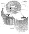
- a central point Z is indicated in a schematic manner. It is about this central point Z around a central transmitting and receiving unit with a bidirectional Transmission and reception circuit. This central point Z is supposed to be centrally any external Record measurement data.
- the radio area FZ of the central station Z is indicated by a circle. This radio area FZ is the transmission and reception range of the central station Z.
- Five data points D1 to D5 are also indicated. At these data points D1 to D5 For example, it can be measuring devices that measure data that the Central office Z are to be transferred.
- the radio areas F1 to F5 of the data points D1 to D5, like the radio area FZ of the central station Z, are indicated by circles.
- the data points D1 to D5 are each assigned a transmitting and receiving unit with a bidirectional transmitting and receiving circuit.
- This Bridge point B only has a radio transmission and reception unit itself no data like data points D1 to D5.
- the data retrieval and transmission system works as follows:
- the data of the data point D1 should be transmitted to the central point Z.
- the Central station Z calls the data center D1 by means of its identification number, its data to send the central office Z. Since the data point D1 in the radio area FZ of the central point Z lies, the data point D1 can send its data directly to the central point Z.
- the data point D2 is also in the radio area FZ of the central point Z, it is also on there the data in data point D2 can be called up in a corresponding manner.
- the situation is different with the data of the data point D3 to be transmitted.
- the recipient the data point D3 is outside the radio area FZ of the central point Z, so that the Data center D3 will not respond to the call to central station Z.
- the data point D3 will therefore not report to the central office Z.
- the received ones Data points D1 and D2 are requested to address the data point D3 not received and send their data.
- Data point D3 is outside the radio range F2 of data point D2, but within radio range F1 of data point D1.
- the data point D3 will thus respond to the corresponding call of data point D1 and first send the data from data point D1.
- the data point D1 caches the Data and finally sends it to the central office Z.
- the data point D5 is outside the radio area FZ of the central point Z and especially also outside the radio areas F1 to F4 of the data points D1 to D4. There are thus no data point chain, which is used for the transmission of the data of data point D5 to the central office Z can provide.
- the central office Z will therefore first call up data points D1 and D2, since these are within the radio range FZ lie and always "listen" to whether they are called.
Abstract
Description
Die Erfindung betrifft ein Verfahren zum zentralen Erfassen von an örtlich verteilten Datenstellen anliegenden Verbrauchsdaten in Gebäuden, insbesondere für Heizung und Warmwasser, wobei eine Zentralstelle die Daten von der jeweiligen Datenstelle per Funk abruft und speichert. - Die Erfindung betrifft ferner eine Vorrichtung zur Durchführung des Verfahrens mit einer zentralen Sende- und Empfangseinheit der Zentralstelle mit einer bidirektionalen Sende- und Empfangsschaltung sowie mit den Datenstellen zugeordneten Sende- und Empfangseinheiten ebenfalls mit bidirektionalen Sende- und Empfangsschaltungen.The invention relates to a method for the central recording of data points distributed locally existing consumption data in buildings, especially for heating and hot water, a central station retrieves the data from the respective data point by radio and saves. - The invention further relates to an apparatus for performing the method with a central transmitting and receiving unit of the central office with a bidirectional Transmitter and receiver circuit as well as transmit and associated with the data points Receiver units also with bidirectional transmit and receive circuits.
Ausgangspunkt der Erfindung ist ein Datenabruf- sowie Übertragungssystem, nämlich allgemein alle Datenübertragungen von Meßgeräten oder anderen Systemen zu einem Datensammler in Form eines Zentralsystems bzw. einer Funkzentrale. Erfindungsgemäßes Anwendungsgebiet dieses Datenabruf- und Übertragungssystems sind Hauszentralen für die Verbrauchsdatenerfassung, Industriegebäude für die Verbrauchsdatenerfassung, Überwachung von verschiedenen Meßwerten, Datenübertragungen von verschiedenen Orten an einen zentralen Punkt, Datenabrufe von Meßgeräten über Modern und andere Femanschlußsysteme sowie Momentankonstrollen von verschiedenen Meßgeräten.The starting point of the invention is a data retrieval and transmission system, namely in general all data transfers from measuring devices or other systems to a data collector in the form of a central system or a radio center. Field of application according to the invention this data retrieval and transmission system are home centers for Consumption data acquisition, industrial building for consumption data acquisition, monitoring from different measured values, data transfers from different locations a central point, data retrieval from measuring devices via modern and other remote connection systems as well as instant checks of various measuring devices.
Das Hauptanwendungsgebiet ist - neben den anderen, zuvor genannten Anwendungsmöglichkeiten - insbesondere die Datenabfrage, Datenspeicherung sowie Datenübertragung mittels eines Funksystems zur zentralen, verbrauchsabhängigen Datenerfassung der Kosten für Heizung und Warmwasser. Das bekannte Verfahren sieht dabei Meßdatenstellen beispielsweise an Heizkörpern vor, welche über Funk mit einer Zentrale verbunden sind. Dabei sind die Funkzentrale sowie alle Meßgeräte mit einer bidirektionalen Sende- und Empfangsschaltung ausgestattet. Das Ablesen per Funk der einzelnen Meßgeräte stellt eine problemlose, zeitsparende sowie präzise Übertragungsmöglichkeit der dezentralen Verbrauchsdaten auf ein zentrales Erfassungssystem dar ohne aufwendige und teure Verkabelung. Dieses Verbrauchsdatenerfassungssystem schließt vor allem mögliche menschliche Ablese- und Eingabefehler aus. Wohnungen müssen nicht betreten werden, und damit sind Terminabsprachen mit den Bewohnern nicht notwendig.The main area of application is - besides the other previously mentioned applications - In particular the data query, data storage and data transmission by means of a radio system for central, consumption-based data acquisition of costs for heating and hot water. The known method sees measurement data points For example, on radiators that are connected to a central station by radio. The radio center and all measuring devices with a bidirectional transmitter and Receiving circuit equipped. The reading by radio of the individual measuring devices provides a problem-free, time-saving and precise transmission option for the decentralized Consumption data on a central recording system without complex and expensive cabling. Above all, this consumption data acquisition system excludes possible human Reading and input errors. Apartments do not have to be entered, and so Appointments with the residents are not necessary.
Neben den genannten Vorteilen hat das erfindungsgemäße Erfassungssystem für die gewünschten Daten auch kleinere Mängel und Nachteile. So benötigt man beispielsweise in der Funkzentrale einen sehr hohen, signaleingangsempfindlichen Empfänger, welcher dadurch verhältnismäßig teuer ist. Oder man benötigt alternativ Sender mit sehr hoher Sendeleistung, was bei Batteriegeräten wegen der Lebensdauer und dem Strombedarf nicht immer möglich ist. Deshalb ist man gezwungen, mehrere Empfänger oder Antennen zu installieren, welche direkt mit der Funkzentrale verbunden sind. Dies führt aber zu einem erhöhten Montage- und Installationsaufwand. Die Investition eines weiteren Empfängers wird aber von den Anwendern oft nicht akzeptiert, wenn Meßgeräte außerhalb des Empfangsbereiches liegen. Weiterhin ist eine vollständige Ausmessung von Anlagen oder Gebäuden meist unmöglich oder wirtschaftlich nicht mehr vertretbar. Grundsätzlich müßten aber die Gebäude hinsichtlich ihrer Empfangsmöglichkeiten ausgemessen werden. Oft führen nämlich bauliche Gegebenheiten zu Empfangseinschränkungen, wenn durch diese bauliche Gegebenheiten die Sendedaten verschiedener Meßgeräte nicht zur Zentrale gelangen können.In addition to the advantages mentioned, the detection system according to the invention has the desired ones Data also minor flaws and disadvantages. For example, one needs in the radio control center has a very high receiver, which is sensitive to signal input is relatively expensive. Or alternatively you need transmitters with very high transmission power, which is not the case with battery devices because of their service life and power consumption is always possible. So you are forced to install multiple receivers or antennas, which are directly connected to the radio center. But this leads to an increased Assembly and installation effort. The investment of another recipient will but often not accepted by users when measuring devices are outside the reception range lie. Furthermore, a complete measurement of plants or buildings mostly impossible or economically unjustifiable. Basically, they should Buildings are measured in terms of their reception options. Often lead structural conditions to reception restrictions, if by this structural Circumstances the transmission data of different measuring devices cannot get to the control center.
Davon ausgehend liegt der Erfindung die Aufgabe zugrunde, sämtliche Datenstellen auch dann sicher von der Zentralstelle erfassen zu können, wenn sie außerhalb des Empfangsbereiches des Empfängers der Zentralstelle sind oder wenn durch bauliche Gegebenheiten die Sendedaten verschiedener Datenstellen nicht zur Zentralstelle gelangen können.Proceeding from this, the object of the invention is to be able to securely capture all data points from the central point even if they are outside the reception area of the recipient of the central point or if the transmission data of different data points cannot reach the central point due to structural conditions.
Als technische Lösung wird mit der Erfindung verfahrensmäßig vorgeschlagen, daß bei Nichterreichen einer bestimmten Datenstelle durch die Zentralstelle diese Zentralstelle eine erreichbare Datenstelle oder eine anderweitige, erreichbare Brückenstelle anfunkt und daß diese erreichbare Datenstelle oder Brückenstelle daraufhin die anfänglich nicht erreichbare Datenstelle unmittelbar oder mittelbar anfunkt und bei Erreichen die Daten per Funk abruft und an die Zentralstelle weitersendet. As a technical solution is proposed procedurally with the invention that is not reached a particular data point anfunkt by the central office, this central station a reachable data point or otherwise achievable bridge point and that this reachable data point or bridge point then, the initially non-reachable data point anfunkt directly or indirectly, and Reaches the data by radio and sends it to the central office.
Dadurch ist ein Datenabruf- und Übertragungssystem geschaffen, welches keine Empfangseinschränkungen durch bauliche Gegebenheiten oder durch zu weit entfernt liegende Datenstellen zur Zentralstelle aufweist. So müssen die Gebäude hinsichtlich ihrer Empfangsmöglichkeiten nicht mehr ausgemessen werden. Die erfindungsgemäße Grundidee besteht dabei darin, daß die im Empfangsbereich der Zentralstelle liegenden Datenstellen dazu benutzt und beauftragt werden, die nicht empfangenen Datenstellen anzusprechen und deren Daten abzurufen und an die Zentralstelle weiterzuleiten. So ruft die Zentralstelle die entsprechenden, erreichbaren Datenstellen mittels ihrer Identifikationsnummer auf, ihre Daten an die Zentralstelle zu senden. Meldet sich eine oder mehrere Datenstellen nicht, so werden die empfangenen Datenstellen aufgefordert, die nicht empfangenen Datenstellen anzusprechen und ihre Daten über die so zwischengeschaltete Datenstelle an die Zentralstelle weiterzusenden. Sofern die von der Zentralstelle angesteuerten Datenstellen die gewünschte Datenstelle immer noch nicht erreichen, so müssen - wie noch näher auszuführen sein wird - weitere Datenübertragungsstellen zwischengeschaltet werden. Darunter wird dann eine mittelbare Datenübertragung verstanden. Sofern die von der Zentralstelle direkt angefunkte Datenstelle gleich die Verbindung zu der gewünschten Datenstelle herstellen kann, wird darunter eine unmittelbare Datenübertragung verstanden. Ist eine Datenstelle außerhalb des Empfangsbereiches der nächst an ihr liegenden Datenstelle, so kann man diese Strecke mit einer Zwischenstelle in Form einer Blinddatenstelle funktechnisch überbrücken, so daß auch für diesen Fall die Datenübertragung möglich ist. Es handelt sich somit bei dieser Zwischenstelle um eine neutrale Einheit, welche nur dem Datentransfer dient und an der selbst keine Meßdaten anliegen. Dieser reine Datenübertrager wird also dann eingesetzt, um ein außerhalb des Empfangsbereiches eines bestimmten Meßgerätes liegendes weiteres Meßgerät trotzdem noch empfangen zu können.This creates a data retrieval and transmission system that has no reception restrictions due to structural conditions or due to too far away Has data points to the central office. So the buildings need to be able to receive them can no longer be measured. The basic idea according to the invention consists in the fact that the data points located in the reception area of the central station be used and instructed to address the data points not received and retrieve their data and forward them to the central office. So the central office calls the corresponding, accessible data points using their identification number on their Send data to the central office. If one or more data points do not respond, so the received data points are requested, the not received data points to address and their data via the intermediate data point to the central office to forward. If the data points controlled by the central point are the desired ones Still not reach the data point, so we have to explain how will be - further data transmission points are interposed. Below that then understood an indirect data transmission. Provided that directly from the central office establish the connection to the desired data point can be understood as direct data transmission. Is a data point outside the reception area of the data point closest to it, one can bridge this route with an intermediate point in the form of a blind data point, so that data transmission is also possible in this case. So it is at this intermediate point a neutral unit, which is only used for data transfer and on which there are no measurement data. This pure data transmitter will then used to be outside the reception range of a specific measuring device to still be able to receive another measuring device.
Eine Weiterbildung des erfindungsgemäßen Verfahrens schlägt vor, daß bei erneutem Nichterreichen der anfänglich nicht erreichten Datenstelle von den durch die Zentralstelle erreichbaren Datenstellen oder Brückenstellen kaskadenartig weitere erreichbare Datenstellen oder Brückenstellen angefunkt werden bis die Verbindung zu der anfänglich nicht erreichten Datenstelle hergestellt ist und daß ausgehend von der anfänglich nicht erreichten Datenstelle die an die Zentralstelle zu übertragenden Daten auf dem umgekehrten Verbindungsweg von Datenstelle/Brückenstelle zu Datenstelle/Brückenstelle weitergesendet werden. Diese Weiterschaltung bzw. Zwischenabfragung von entsprechenden Datenstellen kann kaskadenweise beliebig oft erweitert werden. Beispielsweise kann eine Datenstelle von der Zentralstelle die Aufforderung bekommen, eine bestimmte Datenstelle anzurufen. Ruft nun diese Datenstelle die gewünschte Datenstelle auf und diese meldet sich nicht, so kann die vorliegende Datenstelle die Aufforderung an andere Datenstellen weitergeben. Dadurch kann eine beliebig lange Kette aufgebaut werden, die nur zeitlich eine Begrenzung findet. Das System sucht sich somit selbständig den richtigen Weg zum Ziel, nämlich zu der zunächst nicht erreichten Datenstelle, welche ihre Daten an die Zentralstelle senden soll. Durch die Besonderheit, daß alle Datenstellen, welche die Aufforderung hören, den Sendebefehl an die gewünschte Datenstelle weitergeben, ist es auch nicht notwendig, in der Zentralstelle einen Lageplan abzulegen, d.h. die Zentralstelle muß nicht wissen, wo die Datenstellen installiert sind, da alle empfangenen Datenstellen quasi gleichzeitig nach den nicht empfangenen Datenstellen "rufen bzw. suchen". Dieses System wirkt durch diese Weiterbildung wie ein Schneeballeffekt, d.h. die Zentralstelle als Punkt ruft die Datenstellen auf und alle im Empfangskreis der Zentralstelle liegenden Datenstellen werden empfangen. Die nicht empfangenen Datenstellen werden durch die empfangenen Datenstellen in ihren jeweiligen Empfangskreisen gesucht und empfangen. Die hier nicht empfangenen Datenstellen werden nun von den neu empfangenen Datenstellen entsprechend aufgefordert, ihre Daten im zusätzlich geschaffenen Empfangskreis zu senden.A further development of the method according to the invention suggests that when the process is repeated Failure to reach the data point not initially reached by the central point accessible data points or bridge points cascade-like further accessible data points or bridge points are radioed until the connection to the initially is not reached data point is established and that starting from the initially not reached Data point the data to be transmitted to the central point on the reverse connection path sent from data point / bridge point to data point / bridge point become. This forwarding or interrogation of corresponding data points can be expanded as often as required in cascades. For example, a data point receive a request from the central office to call a certain data center. If this data point calls the desired data point and it does not respond, so the present data point can forward the request to other data points. As a result, an arbitrarily long chain can be built, which is only limited in time finds. The system thus independently searches for the right path to the goal, namely to the initially not reached data center, which should send its data to the central office. The peculiarity that all data points that hear the request, the send command forward to the desired data center, it is also not necessary in the central office to file a site plan, i.e. the central office does not have to know where the data offices are are installed, since all received data points quasi simultaneously after the not "Call or search" received data points. This system works through this training like a snowball effect, i.e. the central office as a point calls up the data offices and all data points in the reception area of the central station are received. The data points not received are received by the received data points in their respective Reception groups searched and received. The data points not received here are now prompted accordingly by the newly received data points, to send their data in the additionally created reception group.
Eine weitere Weiterbildung des erfindungsgemäßen Verfahrens schlägt vor, daß sämtliche erreichbaren Datenstellen oder Brückenstelle der Reihe nach angefunkt werden bis eine Verbindung zu der anfänglich nicht erreichten Datenstelle hergestellt ist. Dadurch ist gewährleistet, daß sämtliche Möglichkeiten ausgeschöpft werden, um die Verbindung zu einer gewünschten Datenstelle herzustellen.A further development of the method according to the invention proposes that all accessible data points or bridging points are radioed in order to one Connection to the data point not initially reached is established. This ensures that all possibilities are exhausted to connect to a create the desired data point.
Eine weitere Weiterbildung schlägt vor, daß die Daten von der Datenstelle oder Brückenstelle zunächst zwischengespeichert und anschließend weitergesendet werden. Selbstverständlich ist es alternativ auch denkbar, die Daten nicht zwischenzuspeichern, sondern sie direkt weiterzusenden.Another development suggests that the data from the data point or bridge point first cached and then forwarded. Of course it is alternatively also conceivable not to temporarily store the data, but rather to store it to forward directly.
Eine weitere Weiterbildung schlägt vor, daß unterschiedliche Sendestartzeiten der einzelnen Datenstellen aus einem vorgegebenen Algorithmus und einer Datenstellenidentifikation in jeder Datenstelle für sich berechnet wird. Dadurch werden Überschneidungen beim Senden der entsprechenden Datenstellen verhindert.Another development suggests that different broadcast start times for the individual Data points from a given algorithm and a data point identification is calculated individually in each data point. This will overlap when sending the corresponding data points prevented.
Als Alternative wird vorgeschlagen, daß die Zentralstelle die Daten aus den einzelnen Datenstellen zeitverzögert anfordert. Dies wird durch eine zeitverzögerte Datenanforderung der Zentrale im Protokoll als Definition bzw. Zeitfaktor als Wartezeit ermöglicht. As an alternative, it is proposed that the central office use the data from the individual data centers requests delayed. This is due to a delayed data request the control center allows in the protocol as definition or time factor as waiting time.
Als technische Lösung wird mit der Erfindung vorrichtungsmäßig vorgeschlagen, daß die Sende- und Empfangseinheiten der Datenstellen untereinander sende- und empfangsfähig sind.As a technical solution , the device proposes that the transmitting and receiving units of the data points are capable of transmitting and receiving among themselves.
Dadurch wird die Möglichkeit geschaffen, daß die Datenstellen nicht nur mit der Zentralstelle über Funk kommunizieren können, sondern daß die Datenstellen direkt miteinander kommunizieren und in der Art einer Kette oder Kaskade Daten empfangen und weitersenden können.This creates the possibility that the data points not only with the central office can communicate via radio, but that the data points directly with each other communicate and receive and forward data in the manner of a chain or cascade can.
Schließlich wird in einer Weiterbildung der Vorrichtung vorgeschlagen, daß zusätzlich zu den Empfangs- und Sendeeinheiten der Datenstellen Brücken-Empfangs/Sendeeinheiten für einen reinen Datentransfer vorgesehen sind. Ist somit einmal eine Datenstelle außerhalb des Empfangsbereiches der nächst an ihr liegenden Datenstelle, so kann man diese Strecke mit einem Blindgerät funktechnisch halbieren und auf diese Weise eine Datenübertragung dennoch ermöglichen.Finally, it is proposed in a further development of the device that in addition to the receiving and transmitting units of the data points bridge receiving / transmitting units are provided for a pure data transfer. So once a data point is outside of the reception area of the data point closest to it, this distance can be seen Halve in terms of radio technology with a blind device and thus transmit data enable nevertheless.
Ein Ausführungsbeispiel der Erfindung wird nachfolgend anhand der Zeichnung beschrieben. In dieser ist in rein perspektivisch-schematischer Weise das erfindungsgemäße Verfahren zum zentralen Erfassen von an örtlich verteilten Datenstellen anliegenden Daten dargestellt.An embodiment of the invention is described below with reference to the drawing. This is the method according to the invention in a purely perspective-schematic manner for the central acquisition of data present at locally distributed data points shown.
Zunächst ist eine Zentralstelle Z in schematischer Weise angedeutet. Es handelt sich bei dieser Zentralstelle Z um eine zentrale Sende- und Empfangseinheit mit einer bidirektionalen Sende- und Empfangsschaltung. Diese Zentralstelle Z soll zentral irgendwelche externen Meßdaten erfassen. Der Funkbereich FZ der Zentralstelle Z ist durch einen Kreis angedeutet. Dieser Funkbereich FZ ist die Sende- und Empfangsreichweite der Zentralstelle Z.First, a central point Z is indicated in a schematic manner. It is about this central point Z around a central transmitting and receiving unit with a bidirectional Transmission and reception circuit. This central point Z is supposed to be centrally any external Record measurement data. The radio area FZ of the central station Z is indicated by a circle. This radio area FZ is the transmission and reception range of the central station Z.
Weiterhin sind fünf Datenstellen D1 bis D5 angedeutet. Bei diesen Datenstellen D1 bis D5 kann es sich beispielsweise um Meßgeräte handeln, welche Daten messen, die dann der Zentralstelle Z übertragen werden sollen. Die Funkbereiche F1 bis F5 der Datenstellen D1 bis D5 sind gleichermaßen wie der Funkbereich FZ der Zentralstelle Z durch Kreise angedeutet. Den Datenstellen D1 bis D5 ist ebenso wie bei der Zentralstelle Z jeweils eine Sende- und Empfangseinheit mit einer bidirektionalen Sende- und Empfangsschaltung zugeordnet. Five data points D1 to D5 are also indicated. At these data points D1 to D5 For example, it can be measuring devices that measure data that the Central office Z are to be transferred. The radio areas F1 to F5 of the data points D1 to D5, like the radio area FZ of the central station Z, are indicated by circles. As with the central station Z, the data points D1 to D5 are each assigned a transmitting and receiving unit with a bidirectional transmitting and receiving circuit.
Schließlich ist noch eine Brückenstelle B mit ihrem Funkbereich FB angedeutet. Diese Brückenstelle B weist lediglich eine funktechnische Sende- und Empfangseinheit auf, erzeugt selbst aber keine Daten wie die Datenstellen D1 bis D5.Finally, a bridge point B with its radio area FB is indicated. This Bridge point B only has a radio transmission and reception unit itself no data like data points D1 to D5.
Die Funktionsweise des Datenabruf- und Übertragungssystems ist wie folgt:The data retrieval and transmission system works as follows:
Zunächst sollen die Daten der Datenstelle D1 der Zentralstelle Z übertragen werden. Die Zentralstelle Z ruft die Datenstelle D1 mittels ihrer Identifikationsnummer auf, ihre Daten an die Zentralstelle Z zu senden. Da die Datenstelle D1 im Funkbereich FZ der Zentralstelle Z liegt, kann die Datenstelle D1 direkt ihre Daten der Zentralstelle Z senden.First of all, the data of the data point D1 should be transmitted to the central point Z. The Central station Z calls the data center D1 by means of its identification number, its data to send the central office Z. Since the data point D1 in the radio area FZ of the central point Z lies, the data point D1 can send its data directly to the central point Z.
Da auch die Datenstelle D2 im Funkbereich FZ der Zentralstelle Z liegt, ist auch dort auf entsprechende Weise ein Abruf der in der Datenstelle D2 vorliegenden Daten möglich.Since the data point D2 is also in the radio area FZ of the central point Z, it is also on there the data in data point D2 can be called up in a corresponding manner.
Anders sieht es mit den zu übertragenden Daten der Datenstelle D3 aus. Der Empfänger der Datenstelle D3 liegt außerhalb des Funkbereiches FZ der Zentralstelle Z, so daß die Datenstelle D3 nicht auf den Aufruf der Zentralstelle Z reagieren wird. Die Datenstelle D3 wird sich somit bei der Zentralstelle Z nicht melden. In diesem Fall werden die empfangenen Datenstellen D1 und D2 aufgefordert, die nicht empfangene Datenstelle D3 anzusprechen und ihre Daten zu senden. Die Datenstelle D3 liegt zwar außerhalb der Funkbereichs F2 der Datenstelle D2, jedoch innerhalb des Funkbereichs F1 der Datenstelle D1. Die Datenstelle D3 wird somit auf den entsprechenden Aufruf der Datenstelle D1 reagieren und zunächst die Daten der Datenstelle D1 senden. Die Datenstelle D1 zwischenspeichert die Daten und sendet sie schließlich an die Zentralstelle Z weiter.The situation is different with the data of the data point D3 to be transmitted. The recipient the data point D3 is outside the radio area FZ of the central point Z, so that the Data center D3 will not respond to the call to central station Z. The data point D3 will therefore not report to the central office Z. In this case, the received ones Data points D1 and D2 are requested to address the data point D3 not received and send their data. Data point D3 is outside the radio range F2 of data point D2, but within radio range F1 of data point D1. The data point D3 will thus respond to the corresponding call of data point D1 and first send the data from data point D1. The data point D1 caches the Data and finally sends it to the central office Z.
Bei der Übertragung der Daten der Datenstelle D4 an die Zentralstelle Z ist der Weg noch weiter. Da die Datenstelle D4 sowohl außerhalb des Funkbereichs FZ der Zentralstelle Z als auch außerhalb des Funkbereichs F1 der Datenstelle D1 liegt, wird die Datenstelle D4 auf den Aufruf der zusätzlich von der Zentralstelle Z eingeschalteten Datenstelle D1 nicht reagieren. Deshalb wird die Datenstelle D1 sämtliche in ihrem Funkbereich F1 liegenden Datenstellen aufrufen und diese auffordern, den Kontakt zu der Datenstelle D4 herzustellen. Dies wird die Datenstelle D3 sein. Da die Datenstelle D4 im Funkbereich F3 der Datenstelle D3 liegt, kann die Datenstelle D3 wiederum die Datenstelle D4 aufrufen, so daß die Datenstelle D4 über die Datenstelle D3 und D1 die Daten an die Zentralstelle Z überträgt.The way is still when the data of the data point D4 is transferred to the central point Z. further. Since the data point D4 both outside the radio area FZ of the central station Z as is also outside the radio range F1 of the data point D1, the data point D4 is opened the call of the data center D1 additionally switched on by the central station Z does not respond. Therefore, the data point D1 becomes all data points in its radio area F1 call and ask them to make contact with data point D4. This will be data point D3. Since the data point D4 in the radio area F3 of the data point D3 lies, the data point D3 can in turn call the data point D4, so that the data point D4 transmits the data to the central point Z via the data point D3 and D1.
Während bisher die Datenstellen D1 bis D4 in ihren gegenseitigen Funkbereichen F1 bis F4 liegen, liegt die Datenstelle D5 außerhalb des Funkbereichs FZ der Zentralstelle Z sowie vor allem auch außerhalb der Funkbereiche F1 bis F4 der Datenstellen D1 bis D4. Es gibt somit keine Datenstellen-Kette, welche für die Übertragung der Daten der Datenstelle D5 zur Zentralstelle Z sorgen kann. Um aber eine Übertragung dennoch zu gewährleisten, dient die Brückenstelle B, welche selbst keine eigenen Daten erzeugt. Die Zentralstelle Z wird somit zunächst die Datenstellen D1 und D2 aufrufen, da diese innerhalb des Funkbereichs FZ liegen und immer "mithören", ob sie aufgerufen werden. Da die Brückenstelle B innerhalb des Funkbereiches F2 der Datenstelle D2 liegt und - ebenso wie die anderen Datenstellen - immer in Hörbereitschaft ist, kann die Datenstelle D2 die Brückenstelle B aufrufen. Da schließlich die gewünschte Datenstelle D5 im Funkbereich FB der Brückenstelle B liegt, kann sie aufgerufen werden und ihre Daten über den Weg Brükenstelle B / Datenstelle D2 der Zentralstelle Z übertragen. While previously the data points D1 to D4 in their mutual radio areas F1 to F4 lie, the data point D5 is outside the radio area FZ of the central point Z and especially also outside the radio areas F1 to F4 of the data points D1 to D4. There are thus no data point chain, which is used for the transmission of the data of data point D5 to the central office Z can provide. However, to ensure a transmission serves the bridge point B, which itself does not generate its own data. The central office Z will therefore first call up data points D1 and D2, since these are within the radio range FZ lie and always "listen" to whether they are called. Since the bridge point B lies within the radio range F2 of the data point D2 and - like the others Data points - is always ready to listen, data point D2 can bridge point B call. Finally, the desired data point D5 in the radio area FB of the bridge point B lies, it can be called up and its data via the route Transfer data point D2 to the central point Z.
- BB
- BrückenstelleBridge point
- D1 bis D5D1 to D5
- DatenstellenData points
- ZZ.
- ZentralstelleCentral office
- FBFB
- Funkbereich Brückenstelle BRadio area bridge point B
- F1 bis F5F1 to F5
- Funkbereiche Datenstellen D1 bis D5Radio areas of data points D1 to D5
- FZFZ
- Funkbereich Zentralstelle ZRadio area central station Z
Claims (8)
wobei eine Zentralstelle (Z) die Daten von der jeweiligen Datenstelle (D1 bis D5) per Funk abruft und speichert,
dadurch gekennzeichnet,
a central point (Z) retrieves and stores the data from the respective data point (D1 to D5) by radio,
characterized by
dadurch gekennzeichnet,
characterized,
dadurch gekennzeichnet,
characterized,
dadurch gekennzeichnet,
characterized,
dadurch gekennzeichnet,
characterized,
dadurch gekennzeichnet,
characterized,
sowie mit den Datenstellen (D1 bis D5) zugeordneten Sende- und Empfangseinheiten ebenfalls mit bidirektionalen Sende- und Empfangsschaltungen,
dadurch gekennzeichnet,
as well as with transmitting and receiving units assigned to the data points (D1 to D5) also with bidirectional transmitting and receiving circuits,
characterized by
dadurch gekennzeichnet,
characterized,
Applications Claiming Priority (2)
| Application Number | Priority Date | Filing Date | Title |
|---|---|---|---|
| DE19741085 | 1997-09-18 | ||
| DE19741085A DE19741085C2 (en) | 1997-09-18 | 1997-09-18 | Process for the central recording of consumption data in buildings located at locally distributed data points, in particular for heating and hot water |
Publications (3)
| Publication Number | Publication Date |
|---|---|
| EP0903953A2 true EP0903953A2 (en) | 1999-03-24 |
| EP0903953A3 EP0903953A3 (en) | 2002-04-24 |
| EP0903953B1 EP0903953B1 (en) | 2005-03-16 |
Family
ID=7842761
Family Applications (1)
| Application Number | Title | Priority Date | Filing Date |
|---|---|---|---|
| EP98117226A Expired - Lifetime EP0903953B1 (en) | 1997-09-18 | 1998-09-11 | Method for the central reading of utility meter data attached to locally distributed data sites in buildings, particularly for heating and hot water |
Country Status (3)
| Country | Link |
|---|---|
| EP (1) | EP0903953B1 (en) |
| AT (1) | ATE291337T1 (en) |
| DE (2) | DE19741085C2 (en) |
Cited By (3)
| Publication number | Priority date | Publication date | Assignee | Title |
|---|---|---|---|---|
| EP1265450A2 (en) * | 2001-06-04 | 2002-12-11 | Schlumberger Resource Management Services, Inc. | System for reading utility meters |
| EP1608200A1 (en) * | 2004-06-16 | 2005-12-21 | Actaris SAS | Method for meter reading using radio frequencies |
| EP1672954A3 (en) * | 2004-12-20 | 2008-03-19 | EMH Elektrizitätszähler GmbH & Co KG | Device and method for recording meter readings |
Families Citing this family (4)
| Publication number | Priority date | Publication date | Assignee | Title |
|---|---|---|---|---|
| DE10123251C1 (en) * | 2001-03-12 | 2002-10-31 | Techem Service Ag | Radio system for consumption data acquisition |
| DE10138229B4 (en) * | 2001-08-03 | 2009-10-01 | Siemens Gebäudesicherheit GmbH & Co. oHG | Method for radio transmission in a hazard detection system |
| DE10318156B4 (en) * | 2003-04-17 | 2005-09-01 | Diehl Ako Stiftung & Co. Kg | Method for announcing a device in a system |
| DE102007042140B4 (en) * | 2007-09-05 | 2011-12-29 | Qundis Gmbh | Radio transmission of data |
Citations (4)
| Publication number | Priority date | Publication date | Assignee | Title |
|---|---|---|---|---|
| US4940976A (en) * | 1988-02-05 | 1990-07-10 | Utilicom Inc. | Automated remote water meter readout system |
| DE19706613A1 (en) * | 1996-02-21 | 1997-08-28 | Minol Messtechnik W Lehmann Gm | Detecting consumption of heat or heating charge proportion etc. or energy consumption |
| US5719564A (en) * | 1996-05-10 | 1998-02-17 | Sears; Lawrence M. | Utility meter reading system |
| US6073169A (en) * | 1997-04-08 | 2000-06-06 | Abb Power T&D Company Inc. | Automatic meter reading system employing common broadcast command channel |
-
1997
- 1997-09-18 DE DE19741085A patent/DE19741085C2/en not_active Expired - Fee Related
-
1998
- 1998-09-11 EP EP98117226A patent/EP0903953B1/en not_active Expired - Lifetime
- 1998-09-11 AT AT98117226T patent/ATE291337T1/en active
- 1998-09-11 DE DE59812654T patent/DE59812654D1/en not_active Expired - Lifetime
Patent Citations (4)
| Publication number | Priority date | Publication date | Assignee | Title |
|---|---|---|---|---|
| US4940976A (en) * | 1988-02-05 | 1990-07-10 | Utilicom Inc. | Automated remote water meter readout system |
| DE19706613A1 (en) * | 1996-02-21 | 1997-08-28 | Minol Messtechnik W Lehmann Gm | Detecting consumption of heat or heating charge proportion etc. or energy consumption |
| US5719564A (en) * | 1996-05-10 | 1998-02-17 | Sears; Lawrence M. | Utility meter reading system |
| US6073169A (en) * | 1997-04-08 | 2000-06-06 | Abb Power T&D Company Inc. | Automatic meter reading system employing common broadcast command channel |
Cited By (5)
| Publication number | Priority date | Publication date | Assignee | Title |
|---|---|---|---|---|
| EP1265450A2 (en) * | 2001-06-04 | 2002-12-11 | Schlumberger Resource Management Services, Inc. | System for reading utility meters |
| EP1265450A3 (en) * | 2001-06-04 | 2003-11-19 | Schlumberger Resource Management Services, Inc. | System for reading utility meters |
| EP1608200A1 (en) * | 2004-06-16 | 2005-12-21 | Actaris SAS | Method for meter reading using radio frequencies |
| FR2871981A1 (en) * | 2004-06-16 | 2005-12-23 | Actaris Sas Soc Par Actions Si | RADIO FREQUENCY COUNTER READING METHOD |
| EP1672954A3 (en) * | 2004-12-20 | 2008-03-19 | EMH Elektrizitätszähler GmbH & Co KG | Device and method for recording meter readings |
Also Published As
| Publication number | Publication date |
|---|---|
| ATE291337T1 (en) | 2005-04-15 |
| EP0903953A3 (en) | 2002-04-24 |
| EP0903953B1 (en) | 2005-03-16 |
| DE19741085C2 (en) | 2002-03-21 |
| DE19741085A1 (en) | 1999-04-01 |
| DE59812654D1 (en) | 2005-04-21 |
Similar Documents
| Publication | Publication Date | Title |
|---|---|---|
| DE3342430C2 (en) | ||
| EP0766881B1 (en) | Control system for several distributed consumers and process for setting said control system into operation | |
| DE3709013A1 (en) | LOAD CONTROL SYSTEM WITH A BRIDGE CONTROL | |
| EP1088294B1 (en) | Automation system with radio sensor | |
| CH673184A5 (en) | Mobile radio communication system - has each mobile station switched in synchronism with interrogation by central station | |
| EP1717927B1 (en) | Powerline control system | |
| EP0903953B1 (en) | Method for the central reading of utility meter data attached to locally distributed data sites in buildings, particularly for heating and hot water | |
| EP0267528B1 (en) | Digital data transmission system with adressable repeaters having fault localization devices | |
| DE3110054A1 (en) | PIPELINE SYSTEM, ESPECIALLY FROM HEAT-INSULATED REMOTE HEAT PIPES | |
| DE102005022989A1 (en) | Modular system for obtaining and relaying measurement data, has measurement data sender and data receiving device combined as repeater | |
| EP0293627A1 (en) | Radio transmission method | |
| DE2333137C3 (en) | Cyclical retrieval procedure in a data transmission system | |
| DE4232127C2 (en) | Method for wireless, high-frequency transmission of measured value signals | |
| EP1325282B1 (en) | Method for connecting ignitors in an ignition system | |
| EP0443438B1 (en) | Method and device for warning persons in the track area via a high frequency communications channel | |
| WO1989008354A1 (en) | Process for controlling and/or monitoring and circuit arrangement for implementing the process | |
| DE102007062077B4 (en) | Transmission method of the stored measurement data from consumption meters, in particular heat cost allocators | |
| DE102011075957B4 (en) | Method and system for wireless data transmission | |
| DE1437360A1 (en) | Information transmission system working with scanning | |
| EP2852184A1 (en) | Method for parallel commissioning of network nodes of a radio network | |
| EP1611424B1 (en) | Device for detecting and approximately localising a leakage in a drinking water supply network | |
| WO1989008359A1 (en) | Process for addressing processing units | |
| DE102007042140B4 (en) | Radio transmission of data | |
| EP0392245B1 (en) | Automatic addressing of monitoring and/or control processing units comprised in a digital information transmission system | |
| DE2839864C2 (en) | Participant response system |
Legal Events
| Date | Code | Title | Description |
|---|---|---|---|
| PUAI | Public reference made under article 153(3) epc to a published international application that has entered the european phase |
Free format text: ORIGINAL CODE: 0009012 |
|
| AK | Designated contracting states |
Kind code of ref document: A2 Designated state(s): AT BE CH CY DE DK ES FI FR GB GR IE IT LI LU MC NL PT SE Kind code of ref document: A2 Designated state(s): AT BE CH DE DK ES FR GB IT LI LU NL PT SE |
|
| AX | Request for extension of the european patent |
Free format text: AL;LT;LV;MK;RO;SI |
|
| PUAL | Search report despatched |
Free format text: ORIGINAL CODE: 0009013 |
|
| AK | Designated contracting states |
Kind code of ref document: A3 Designated state(s): AT BE CH CY DE DK ES FI FR GB GR IE IT LI LU MC NL PT SE |
|
| AX | Request for extension of the european patent |
Free format text: AL;LT;LV;MK;RO;SI |
|
| RIC1 | Information provided on ipc code assigned before grant |
Free format text: 7H 04Q 9/00 A, 7G 08C 17/02 B, 7G 01F 15/06 B |
|
| 17P | Request for examination filed |
Effective date: 20020828 |
|
| AKX | Designation fees paid |
Free format text: AT BE CH DE DK ES FR GB IT LI LU NL PT SE |
|
| AXX | Extension fees paid |
Free format text: RO PAYMENT 20020828 |
|
| GRAP | Despatch of communication of intention to grant a patent |
Free format text: ORIGINAL CODE: EPIDOSNIGR1 |
|
| GRAS | Grant fee paid |
Free format text: ORIGINAL CODE: EPIDOSNIGR3 |
|
| GRAA | (expected) grant |
Free format text: ORIGINAL CODE: 0009210 |
|
| AK | Designated contracting states |
Kind code of ref document: B1 Designated state(s): AT BE CH DE DK ES FR GB IT LI LU NL PT SE |
|
| AX | Request for extension of the european patent |
Extension state: RO |
|
| PG25 | Lapsed in a contracting state [announced via postgrant information from national office to epo] |
Ref country code: GB Free format text: LAPSE BECAUSE OF FAILURE TO SUBMIT A TRANSLATION OF THE DESCRIPTION OR TO PAY THE FEE WITHIN THE PRESCRIBED TIME-LIMIT Effective date: 20050316 |
|
| REG | Reference to a national code |
Ref country code: GB Ref legal event code: FG4D Free format text: NOT ENGLISH |
|
| REG | Reference to a national code |
Ref country code: CH Ref legal event code: EP |
|
| REG | Reference to a national code |
Ref country code: IE Ref legal event code: FG4D Free format text: GERMAN |
|
| REF | Corresponds to: |
Ref document number: 59812654 Country of ref document: DE Date of ref document: 20050421 Kind code of ref document: P |
|
| PG25 | Lapsed in a contracting state [announced via postgrant information from national office to epo] |
Ref country code: DK Free format text: LAPSE BECAUSE OF FAILURE TO SUBMIT A TRANSLATION OF THE DESCRIPTION OR TO PAY THE FEE WITHIN THE PRESCRIBED TIME-LIMIT Effective date: 20050616 |
|
| PG25 | Lapsed in a contracting state [announced via postgrant information from national office to epo] |
Ref country code: ES Free format text: LAPSE BECAUSE OF FAILURE TO SUBMIT A TRANSLATION OF THE DESCRIPTION OR TO PAY THE FEE WITHIN THE PRESCRIBED TIME-LIMIT Effective date: 20050627 |
|
| PG25 | Lapsed in a contracting state [announced via postgrant information from national office to epo] |
Ref country code: PT Free format text: LAPSE BECAUSE OF FAILURE TO SUBMIT A TRANSLATION OF THE DESCRIPTION OR TO PAY THE FEE WITHIN THE PRESCRIBED TIME-LIMIT Effective date: 20050907 |
|
| PG25 | Lapsed in a contracting state [announced via postgrant information from national office to epo] |
Ref country code: IT Free format text: LAPSE BECAUSE OF NON-PAYMENT OF DUE FEES;WARNING: LAPSES OF ITALIAN PATENTS WITH EFFECTIVE DATE BEFORE 2007 MAY HAVE OCCURRED AT ANY TIME BEFORE 2007. THE CORRECT EFFECTIVE DATE MAY BE DIFFERENT FROM THE ONE RECORDED. Effective date: 20050911 |
|
| PG25 | Lapsed in a contracting state [announced via postgrant information from national office to epo] |
Ref country code: LU Free format text: LAPSE BECAUSE OF NON-PAYMENT OF DUE FEES Effective date: 20050930 Ref country code: LI Free format text: LAPSE BECAUSE OF NON-PAYMENT OF DUE FEES Effective date: 20050930 Ref country code: CH Free format text: LAPSE BECAUSE OF NON-PAYMENT OF DUE FEES Effective date: 20050930 |
|
| GBV | Gb: ep patent (uk) treated as always having been void in accordance with gb section 77(7)/1977 [no translation filed] |
Effective date: 20050316 |
|
| PLBE | No opposition filed within time limit |
Free format text: ORIGINAL CODE: 0009261 |
|
| STAA | Information on the status of an ep patent application or granted ep patent |
Free format text: STATUS: NO OPPOSITION FILED WITHIN TIME LIMIT |
|
| 26N | No opposition filed |
Effective date: 20051219 |
|
| PGFP | Annual fee paid to national office [announced via postgrant information from national office to epo] |
Ref country code: BE Payment date: 20060330 Year of fee payment: 8 |
|
| EN | Fr: translation not filed | ||
| REG | Reference to a national code |
Ref country code: CH Ref legal event code: PL |
|
| PG25 | Lapsed in a contracting state [announced via postgrant information from national office to epo] |
Ref country code: BE Free format text: LAPSE BECAUSE OF NON-PAYMENT OF DUE FEES Effective date: 20060930 |
|
| BERE | Be: lapsed |
Owner name: KUNDO SYSTEMTECHNIK G.M.B.H. Effective date: 20060930 |
|
| PG25 | Lapsed in a contracting state [announced via postgrant information from national office to epo] |
Ref country code: SE Free format text: LAPSE BECAUSE OF FAILURE TO SUBMIT A TRANSLATION OF THE DESCRIPTION OR TO PAY THE FEE WITHIN THE PRESCRIBED TIME-LIMIT Effective date: 20050616 |
|
| PG25 | Lapsed in a contracting state [announced via postgrant information from national office to epo] |
Ref country code: FR Free format text: LAPSE BECAUSE OF NON-PAYMENT OF DUE FEES Effective date: 20050930 |
|
| PG25 | Lapsed in a contracting state [announced via postgrant information from national office to epo] |
Ref country code: FR Free format text: LAPSE BECAUSE OF NON-PAYMENT OF DUE FEES Effective date: 20050316 |
|
| PGRI | Patent reinstated in contracting state [announced from national office to epo] |
Ref country code: IT Effective date: 20091201 |
|
| REG | Reference to a national code |
Ref country code: DE Ref legal event code: R081 Ref document number: 59812654 Country of ref document: DE Owner name: QUNDIS GMBH, DE Free format text: FORMER OWNERS: INSTITUT FUER MIKRO-UND INFORMATIONSTECHNIK, 78052 VILLINGEN-SCHWENNINGEN, DE; QUNDIS GMBH, 99974 MUEHLHAUSEN, DE Effective date: 20110301 Ref country code: DE Ref legal event code: R081 Ref document number: 59812654 Country of ref document: DE Owner name: QUNDIS GMBH, DE Free format text: FORMER OWNER: INSTITUT FUER MIKRO-UND INFORMAT, QUNDIS GMBH, , DE Effective date: 20110301 |
|
| REG | Reference to a national code |
Ref country code: DE Ref legal event code: R082 Ref document number: 59812654 Country of ref document: DE Representative=s name: PATENTANWAELTE LIEDTKE & PARTNER, DE Effective date: 20130912 Ref country code: DE Ref legal event code: R081 Ref document number: 59812654 Country of ref document: DE Owner name: QUNDIS GMBH, DE Free format text: FORMER OWNER: QUNDIS GMBH, 99974 MUEHLHAUSEN, DE Effective date: 20130912 |
|
| PGFP | Annual fee paid to national office [announced via postgrant information from national office to epo] |
Ref country code: DE Payment date: 20140926 Year of fee payment: 17 |
|
| PGFP | Annual fee paid to national office [announced via postgrant information from national office to epo] |
Ref country code: AT Payment date: 20140929 Year of fee payment: 17 |
|
| PGFP | Annual fee paid to national office [announced via postgrant information from national office to epo] |
Ref country code: NL Payment date: 20140929 Year of fee payment: 17 |
|
| PGFP | Annual fee paid to national office [announced via postgrant information from national office to epo] |
Ref country code: IT Payment date: 20141023 Year of fee payment: 17 |
|
| REG | Reference to a national code |
Ref country code: DE Ref legal event code: R119 Ref document number: 59812654 Country of ref document: DE |
|
| PG25 | Lapsed in a contracting state [announced via postgrant information from national office to epo] |
Ref country code: IT Free format text: LAPSE BECAUSE OF NON-PAYMENT OF DUE FEES Effective date: 20150911 |
|
| REG | Reference to a national code |
Ref country code: AT Ref legal event code: MM01 Ref document number: 291337 Country of ref document: AT Kind code of ref document: T Effective date: 20150911 |
|
| REG | Reference to a national code |
Ref country code: NL Ref legal event code: MM Effective date: 20151001 |
|
| PG25 | Lapsed in a contracting state [announced via postgrant information from national office to epo] |
Ref country code: DE Free format text: LAPSE BECAUSE OF NON-PAYMENT OF DUE FEES Effective date: 20160401 |
|
| PG25 | Lapsed in a contracting state [announced via postgrant information from national office to epo] |
Ref country code: AT Free format text: LAPSE BECAUSE OF NON-PAYMENT OF DUE FEES Effective date: 20150911 Ref country code: NL Free format text: LAPSE BECAUSE OF NON-PAYMENT OF DUE FEES Effective date: 20151001 |