EP1204255A1 - Method and device for receiving multifrequency radio signals - Google Patents
Method and device for receiving multifrequency radio signals Download PDFInfo
- Publication number
- EP1204255A1 EP1204255A1 EP01402831A EP01402831A EP1204255A1 EP 1204255 A1 EP1204255 A1 EP 1204255A1 EP 01402831 A EP01402831 A EP 01402831A EP 01402831 A EP01402831 A EP 01402831A EP 1204255 A1 EP1204255 A1 EP 1204255A1
- Authority
- EP
- European Patent Office
- Prior art keywords
- signal
- threshold
- phase
- adaptation
- during
- Prior art date
- Legal status (The legal status is an assumption and is not a legal conclusion. Google has not performed a legal analysis and makes no representation as to the accuracy of the status listed.)
- Withdrawn
Links
Images


Classifications
-
- H—ELECTRICITY
- H04—ELECTRIC COMMUNICATION TECHNIQUE
- H04L—TRANSMISSION OF DIGITAL INFORMATION, e.g. TELEGRAPHIC COMMUNICATION
- H04L25/00—Baseband systems
- H04L25/02—Details ; arrangements for supplying electrical power along data transmission lines
- H04L25/06—Dc level restoring means; Bias distortion correction ; Decision circuits providing symbol by symbol detection
- H04L25/061—Dc level restoring means; Bias distortion correction ; Decision circuits providing symbol by symbol detection providing hard decisions only; arrangements for tracking or suppressing unwanted low frequency components, e.g. removal of dc offset
- H04L25/062—Setting decision thresholds using feedforward techniques only
-
- H—ELECTRICITY
- H04—ELECTRIC COMMUNICATION TECHNIQUE
- H04L—TRANSMISSION OF DIGITAL INFORMATION, e.g. TELEGRAPHIC COMMUNICATION
- H04L5/00—Arrangements affording multiple use of the transmission path
- H04L5/02—Channels characterised by the type of signal
- H04L5/06—Channels characterised by the type of signal the signals being represented by different frequencies
Definitions
- the subject of the present invention is a method and a device for receiving radio signals to be picked up on different frequencies or channels.
- a reception which includes a high frequency reception (HF) circuit connected to an antenna and a detection chain (BF) connected to the circuit reception, which amplifies the received signal and which delivers generally a representative digital output signal, in particular with respect to a threshold, of the received signal.
- HF high frequency reception
- BF detection chain
- reception channels As defined above, which deliver their output signals to a processing unit through a multiplexer.
- Such an arrangement is bulky and expensive.
- it generates significant energy consumption electric which constitutes a handicap in the case of a power supply electric by batteries.
- the object of the present invention is to reduce the drawbacks above.
- the present invention firstly provides a method of reception of radio signals, in which a multiplicity of receive circuits are sensitive respectively to signals radio signals to be picked up on different frequencies or channels and respectively have received signal outputs, in order to deliver a representative digital output signal, relative to the minus a threshold, of the signal received on each frequency or channel.
- the method can advantageously consist in generating an origin threshold (S1) adapted to the amplitude of the signal from said single line at the end of said adaptation phase.
- the method can advantageously consist in generating an adapted threshold and a second threshold higher than this adapted threshold; and compare the amplitude of the signal from from the single line to this second threshold at least as long as the amplitude of this signal is less than the value of this second threshold during the phase of detection of each period following its adaptation phase supra.
- the method can advantageously consist, during said detection phase, of doing vary said original threshold by integrating the signal from said line unique.
- the method can advantageously consist in supplying electrical energy only to the circuit detection system selected.
- the method can advantageously consist in extending the listening period in case the signal digital output corresponds to an expected signal.
- the present invention also provides a device for reception of radio signals to be picked up on frequencies or different channels.
- the adaptation means is activated by preferably for a fixed period at the start of each period listening.
- the detection chain comprises preferably a signal integration circuit from said line unique, this circuit being subject to said adaptation means.
- the detection chain can advantageously include means for setting a suitable threshold and a second threshold higher than the first, these means being controlled by said steering body so that the second threshold is activated at least as long as the amplitude of the signal delivered on the single line is lower than the value of this second threshold during the phase of each period following its aforementioned adaptation phase.
- the detection chain comprises preferably a comparator, an input of which is connected to said line unique through resistance and reference potential at across a capacitor and the other input of which is connected to said line unique, this comparator delivering said output signal.
- Said means adapter includes a shorting switch for this resistance activated by said control member during each phase adaptation.
- the detection chain comprises preferably a resistive bridge, said resistance and said capacitor being connected to said comparator input through this bridge so as to generate a second threshold of increased value.
- Said means of adaptation includes a short-circuiting switch for this bridge activated by said control member at least as long as the amplitude of the signal from of the single line is less than the value of this second threshold during the phase of each period following its aforementioned adaptation phase.
- the device preferably comprises a circuit for processing the output signals from the detection chain, acting on said steering member so that the latter extends the duration of a listening period in the event of reception, during this period, of an expected radio signal.
- the detection chain comprises preferably an amplifier mounted between its aforementioned input and its aforementioned detection means.
- the steering unit can advantageously include means for selectively supplying the circuits of reception.
- a device 1 for receiving radio signals which comprises a high frequency reception unit (HF) 2, an amplification chain and low frequency detection (LF) 3 and an electronic control and processing 4, the latter comprising in particular a programmed microprocessor.
- HF high frequency reception unit
- LF low frequency detection
- electronic control and processing 4 the latter comprising in particular a programmed microprocessor.
- the reception unit 2 comprises a reception block 5 consisting of a multiplicity of reception circuits 6, for example super feedback receptors or super heterodyne receptors linked to an antenna. These receiving circuits are respectively sensitive to radio signals to be picked up on frequencies or different channels.
- the signal outputs of the receiving circuits 6 are connected to parallel inputs of a multiplexer 7 by lines 8.
- the output of the multiplexer 7 is connected to the input of the chain detection amplification 3 by a single line 9.
- the steering unit 4 is adapted to control selectively the reception block 5 and the multiplexer 7, through a control line 10, so that the multiplexer 7 delivers signals from its single output line 9 successively and respectively of the receiving circuits 6.
- This operating mode of the reception unit 5 can be ensured by the fact that the control member 4 successively controls the electrical energy supplies of the reception circuits 6 of so as to supply electrical power only to the receiving circuit 6 selected.
- the amplification and detection chain 3 includes a amplifier 11 whose input is connected to the single output line 9 of the multiplexer 7 of the reception unit 2 and the output of which is connected to an integration circuit 12 which has an output line 13.
- This integration circuit 12 includes a resistor 14 connected between the output of amplifier 11 and line 13 and a capacitor 15 connected between line 13 and earth.
- the line 13 and the output of amplifier 11, via line 16 are connected to the inputs of a comparator 17 including the output line digital 18 is connected to a data input of the piloting and processing 4.
- the integration circuit 12 generates a threshold S1 which evolves by integration with the amplitude of the output signal of amplifier 11.
- line 13 is connected to the comparator 17 via a resistive bridge which includes a resistor 19 and a resistor 20 whose common line 21 is connected to the comparator 17.
- This arrangement makes it possible to generate a second threshold S2 whose value is greater than the aforementioned threshold S1 by a value determined by the choice resistors 19 and 20.
- the amplification and detection chain 3 includes in addition to an adaptation member constituted by a switch 22 mounted in parallel to the resistor 14 of the integration circuit 12, this switch 22 allowing, when in the closed position, to short-circuit the resistor 14 and thus directly connect the amplifier output 11 on line 13.
- This switch 22 can be controlled by the control unit 4 via a control line 23.
- the amplification and detection chain 3 includes also a switch 24 connected in parallel to the resistor 19 and can be controlled by the steering body 4 via a line 25, this switch 24 allowing, when in the closed position, to short-circuit the resistor 19 and thus directly connect the line 13 to comparator 17 in order to inhibit threshold S2.
- the receiving device 1 which comes to be described works in the following manner.
- the steering unit 4 When the steering unit 4 triggers a period listening Pe of a selected receiving circuit 6, placing in at the same time the multiplexer 7 in the corresponding position, it commands the closing of switch 22 via the command line 23 to place it in the closed position for a fixed period corresponding to an adaptation phase Pa.
- the amplitude of the signal appearing on line 13 substantially follows the amplitude of the amplifier output signal 11.
- the integration circuit 12 At the end of the adaptation phase Pa, when the switch 22 returns to its open position, the integration circuit 12 generates a adapted original threshold S1 whose original value is substantially equal to the value of the signal from amplifier 11 at this time. he as a result, the amplitude or the value of this original threshold S1 is independent of the state of the amplifier output 11 before the engagement of this listening phase Pe.
- This original adapted threshold S1 then evolves, as described previously, during a detection phase Pd, until the end of the listening period Pe of the selected reception circuit 6.
- the steering body 4 places or maintains this switch 24 in open position preferably at the start of the phase of adaptation Pa, so that the aforementioned threshold S2 is generated.
- the comparator 17 compares the signal from amplifier 11 via line 16 to the threshold value S2.
- the control member 4 controls the switch 24 so as to place it in the closed position so that, by following during the Pd detection phase and until the end of the listening period Pe, the threshold S2 is inhibited and the comparator 17 compares the signal from amplifier 11 via line 16 to threshold S1 generated by the integration circuit 12.
- the control and processing circuit 4 analyzes the signal from line 18 and can order an extension of the listening period Pe.
- the output of amplifier 11 delivers a signal approximately equal to threshold S1 (i) of the integration circuit 12 and that the increased threshold S2 (i) is activated by the fact that the switch 24 is in the open position.
- the steering unit 4 then orders the start of the listening period Pe (i + 1) of a detection circuit 6 (i + 1) newly selected and places the multiplexer in correspondence.
- the control unit 4 orders the closing of the switch of adaptation 22 during the adaptation phase Pa (i + 1).
- the switch 24 remains open.
- an adapted threshold S1 (i + 1) and an increased threshold S2 (i + 1) are generated as described previously, regardless of the previous value of the threshold S1 (i) existing at the end of the listening period Pe (i) associated with the reception 6 (i) previously selected.
- switch 22 is closed and switch 24 for generating increased threshold is open.
- a suitable threshold S1 (j) is generated by the integration circuit 12, the original value of this initial threshold being substantially equal to the value of the signal leaving amplifier 11.
- the comparator 17 compares the value of the signal from amplifier 11 via line 16 by compared to the value of the increased threshold S2 (j).
- a signal for example equal to UN is generated on the output 18 of the comparator 17 and is delivered to the steering and processing unit 4.
- control and processing unit 4 sends a signal to switch 24 via line 25 so as to place it at its closed position.
- the increased threshold S2 (j) is then inhibited and the threshold of comparison used by comparator 17 is then the threshold S1 (j).
- the detection of the signal from amplifier 11 and from the circuit reception 6 (j) continues with respect to this threshold S1 (3).
- the control and processing unit 4 then orders the block 5 to extend the listening period of the receiving circuit 6 (j) selected, for example for a fixed period at least necessary for the acquisition of an expected signal likely to be received by this receiving circuit 6 (j).
- the steering body 4 selects another receiving circuit 6 and generates a period Pe monitoring for this new reception circuit.
Abstract
Description
La présente invention a pour objet un procédé et un dispositif de réception de signaux radioélectriques à capter sur des fréquences ou des canaux différents.The subject of the present invention is a method and a device for receiving radio signals to be picked up on different frequencies or channels.
Habituellement, notamment dans les systèmes d'alarmes, pour capter un signal radioélectrique sur une bande de fréquences dite fréquence de réception ou un canal déterminés, on utilise une voie de réception qui comprend un circuit (HF) de réception haute fréquence relié à une antenne et une chaíne (BF) de détection reliée au circuit de réception, qui assure l'amplification du signal reçu et qui délivre généralement un signal de sortie numérique représentatif, en particulier par rapport à un seuil, du signal reçu. Ce signal de sortie est délivré à un circuit de traitement qui assure son décodage en vue de l'exploiter.Usually, especially in alarm systems, for picking up a radio signal on a so-called frequency band reception frequency or a specific channel, use a reception which includes a high frequency reception (HF) circuit connected to an antenna and a detection chain (BF) connected to the circuit reception, which amplifies the received signal and which delivers generally a representative digital output signal, in particular with respect to a threshold, of the received signal. This output signal is delivered to a processing circuit which ensures its decoding with a view to to exploit it.
Lorsqu'on souhaite recevoir des signaux radioélectriques sur des fréquences ou des canaux différents, on prévoit un nombre correspondant de voies de réception telles que définies ci-dessus, qui délivrent leurs signaux de sortie à une unité de traitement au travers d'un multiplexeur. Une telle disposition est encombrante et coûte cher. De plus, elle engendre une consommation important d'énergie électrique qui constitue un handicap dans le cas d'une alimentation électrique par piles.When you want to receive radio signals on different frequencies or channels, a number is expected correspondent of reception channels as defined above, which deliver their output signals to a processing unit through a multiplexer. Such an arrangement is bulky and expensive. In addition, it generates significant energy consumption electric which constitutes a handicap in the case of a power supply electric by batteries.
La présente invention a pour but de réduire les inconvénients ci-dessus.The object of the present invention is to reduce the drawbacks above.
La présente invention propose tout d'abord un procédé de réception de signaux radioélectriques, dans lequel une multiplicité de circuits de réception sont sensibles respectivement à des signaux radioélectriques à capter sur des fréquences ou des canaux différents et présentent respectivement des sorties de signal reçu, afin de délivrer un signal de sortie numérique représentatif, par rapport à au moins un seuil, du signal reçu sur chaque fréquence ou canal.The present invention firstly provides a method of reception of radio signals, in which a multiplicity of receive circuits are sensitive respectively to signals radio signals to be picked up on different frequencies or channels and respectively have received signal outputs, in order to deliver a representative digital output signal, relative to the minus a threshold, of the signal received on each frequency or channel.
Selon l'invention, le procédé consiste :
- à relier sélectivement, durant des périodes d'écoute successives (Pe), les sorties de signal des circuits de réception à une ligne unique de sortie ;
- à diviser chaque période d'écoute en une phase d'adaptation suivie d'une phase de détection ;
- à, au cours de la phase d'adaptation (Pa) de chaque période d'écoute, annuler le seuil de la phase d'écoute précédente et générer un nouveau seuil d'origine (S1) dont la valeur est adaptée à l'amplitude du signal issu de ladite ligne unique durant cette phase d'adaptation ;
- et à comparer le signal issu de la ligne unique à ce seuil adapté afin de délivrer un signal de sortie numérique représentatif, par rapport à ce seuil, du signal issu de cette ligne unique durant la phase de détection (Pd) de chaque période d'écoute (Pe) succédant à sa phase d'adaptation précitée.
- selectively connecting, during successive listening periods (Pe), the signal outputs of the reception circuits to a single output line;
- dividing each listening period into an adaptation phase followed by a detection phase;
- to, during the adaptation phase (Pa) of each listening period, cancel the threshold of the previous listening phase and generate a new original threshold (S1) whose value is adapted to the amplitude the signal from said single line during this adaptation phase;
- and to compare the signal from the single line with this adapted threshold in order to deliver a digital output signal representative, with respect to this threshold, of the signal from this single line during the detection phase (Pd) of each period of listening (Pe) following its aforementioned adaptation phase.
Selon la présente invention, le procédé peut avantageusement consister à générer un seuil d'origine (S1) adapté à l'amplitude du signal issu de ladite ligne unique au terme de ladite phase d'adaptation.According to the present invention, the method can advantageously consist in generating an origin threshold (S1) adapted to the amplitude of the signal from said single line at the end of said adaptation phase.
Selon la présente invention, le procédé peut avantageusement consister à générer un seuil adapté et un second seuil supérieur à ce seuil adapté ; et à comparer l'amplitude du signal issu de la ligne unique à ce second seuil au moins tant que l'amplitude de ce signal est inférieure à la valeur de ce second seuil durant la phase de détection de chaque période succédant à sa phase d'adaptation précitée.According to the present invention, the method can advantageously consist in generating an adapted threshold and a second threshold higher than this adapted threshold; and compare the amplitude of the signal from from the single line to this second threshold at least as long as the amplitude of this signal is less than the value of this second threshold during the phase of detection of each period following its adaptation phase supra.
Selon la présente invention, le procédé peut avantageusement consister, au cours de ladite phase de détection, à faire varier ledit seuil d'origine par intégration du signal issu de ladite ligne unique.According to the present invention, the method can advantageously consist, during said detection phase, of doing vary said original threshold by integrating the signal from said line unique.
Selon la présente invention, le procédé peut avantageusement consister à n'alimenter en énergie électrique que le circuit de détection sélectionné.According to the present invention, the method can advantageously consist in supplying electrical energy only to the circuit detection system selected.
Selon la présente invention, le procédé peut avantageusement consister à prolonger la période d'écoute au cas où le signal numérique de sortie correspond à un signal attendu.According to the present invention, the method can advantageously consist in extending the listening period in case the signal digital output corresponds to an expected signal.
La présente invention propose également un dispositif de réception de signaux radioélectriques à capter sur des fréquences ou des canaux différents.The present invention also provides a device for reception of radio signals to be picked up on frequencies or different channels.
Selon l'invention, le dispositif comprend :
- une multiplicité de circuits de réception sensibles respectivement à des signaux radioélectriques à capter sur des fréquences ou des canaux différents et présentant respectivement des sorties de signal reçu ;
- un moyen d'aiguillage qui présente des entrées respectivement reliées aux sorties de signal reçu desdits circuits de réception et qui présente une ligne unique de sortie ;
- un organe de pilotage pour commander ledit moyen d'aiguillage de façon à relier sélectivement, durant des périodes d'écoute successives, les entrées de ce moyen d'aiguillage à sa ligne unique de sortie ;
- une chaíne unique de détection présentant une entrée reliée à ladite ligne unique et comprenant un moyen de comparaison pour délivrer un signal de sortie numérique représentatif, par rapport à au moins un seuil, du signal issu de cette ligne unique ;
- et un moyen d'adaptation activé par ledit organe de pilotage et permettant, pendant des phases d'adaptation situées au début de chaque période d'écoute, d'adapter la valeur du seuil précité à l'amplitude du signal issu de ladite ligne unique durant cette phase d'adaptation.
- a multiplicity of reception circuits sensitive respectively to radioelectric signals to be picked up on different frequencies or channels and respectively having received signal outputs;
- switch means which has inputs respectively connected to the signal outputs received from said reception circuits and which has a single output line;
- a control member for controlling said switching means so as to selectively connect, during successive listening periods, the inputs of this switching means to its single output line;
- a single detection chain having an input connected to said single line and comprising a comparison means for delivering a digital output signal representative, with respect to at least one threshold, of the signal from this single line;
- and an adaptation means activated by said control member and making it possible, during adaptation phases situated at the start of each listening period, to adapt the value of the aforementioned threshold to the amplitude of the signal from said single line during this adaptation phase.
Selon l'invention, le moyen d'adaptation est activé de préférence pendant une durée déterminée au début de chaque période d'écoute.According to the invention, the adaptation means is activated by preferably for a fixed period at the start of each period listening.
Selon l'invention, la chaíne de détection comprend de préférence un circuit d'intégration du signal issu de ladite ligne unique, ce circuit étant soumis audit moyen d'adaptation.According to the invention, the detection chain comprises preferably a signal integration circuit from said line unique, this circuit being subject to said adaptation means.
Selon l'invention, la chaíne de détection peut avantageusement comprendre des moyens pour fixer un seuil adapté et un second seuil plus élevé que le premier, ces moyens étant commandés par ledit organe de pilotage de telle sorte que le second seuil est activé au moins tant que l'amplitude du signal délivré sur la ligne unique est inférieure à la valeur de ce second seuil durant la phase de chaque période succédant à sa phase d'adaptation précitée.According to the invention, the detection chain can advantageously include means for setting a suitable threshold and a second threshold higher than the first, these means being controlled by said steering body so that the second threshold is activated at least as long as the amplitude of the signal delivered on the single line is lower than the value of this second threshold during the phase of each period following its aforementioned adaptation phase.
Selon l'invention, la chaíne de détection comprend de préférence un comparateur dont une entrée est reliée à ladite ligne unique au travers d'une résistance et à un potentiel de référence au travers d'un condensateur et dont l'autre entrée est reliée à ladite ligne unique, ce comparateur délivrant ledit signal de sortie. Ledit moyen d'adaptation comprend un interrupteur de court-circuitage de cette résistance activé par ledit organe de pilotage pendant chaque phase d'adaptation.According to the invention, the detection chain comprises preferably a comparator, an input of which is connected to said line unique through resistance and reference potential at across a capacitor and the other input of which is connected to said line unique, this comparator delivering said output signal. Said means adapter includes a shorting switch for this resistance activated by said control member during each phase adaptation.
Selon l'invention, la chaíne de détection comprend de préférence un pont résistif, ladite résistance et ledit condensateur étant reliés à ladite entrée du comparateur au travers de ce pont de façon à générer un second seuil de valeur accrue. Ledit moyen d'adaptation comprend un interrupteur de court-circuitage de ce pont activé par ledit organe de pilotage au moins tant que l'amplitude du signal issu de la ligne unique est inférieure à la valeur de ce second seuil durant la phase de chaque période succédant à sa phase d'adaptation précitée.According to the invention, the detection chain comprises preferably a resistive bridge, said resistance and said capacitor being connected to said comparator input through this bridge so as to generate a second threshold of increased value. Said means of adaptation includes a short-circuiting switch for this bridge activated by said control member at least as long as the amplitude of the signal from of the single line is less than the value of this second threshold during the phase of each period following its aforementioned adaptation phase.
Selon l'invention, le dispositif comprend de préférence un circuit de traitement des signaux de sortie de la chaíne de détection, agissant sur ledit organe de pilotage de façon à ce que ce dernier prolonge la durée d'une période d'écoute en cas de réception, pendant cette période, d'un signal radioélectrique attendu.According to the invention, the device preferably comprises a circuit for processing the output signals from the detection chain, acting on said steering member so that the latter extends the duration of a listening period in the event of reception, during this period, of an expected radio signal.
Selon l'invention, la chaíne de détection comprend de préférence un amplificateur monté entre son entrée précitée et son moyen de détection précité.According to the invention, the detection chain comprises preferably an amplifier mounted between its aforementioned input and its aforementioned detection means.
Selon l'invention, l'organe de pilotage peut avantageusement comprendre des moyens pour alimenter sélectivement les circuits de réception.According to the invention, the steering unit can advantageously include means for selectively supplying the circuits of reception.
La présente invention sera mieux comprise à l'étude d'un dispositif de réception de signaux radioélectriques à capter sur des fréquences ou des canaux différents, décrit à titre d'exemple non limitatif et illustré par le dessin sur lequel :
- la figure 1 représente le schéma électronique d'un dispositif de réception de signaux radioélectriques selon la présente invention ;
- la figure 2 représente un premier diagramme de fonctionnement du dispositif de réception de la figure 1 ;
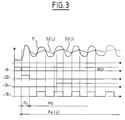
- et la figure 3 représente un second diagramme de fonctionnement du dispositif de réception de la figure 1.
- FIG. 1 represents the electronic diagram of a device for receiving radio signals according to the present invention;
- 2 shows a first operating diagram of the receiving device of Figure 1;
- and FIG. 3 represents a second operating diagram of the reception device of FIG. 1.
En se reportant à la figure 1, on voit qu'on a représenté un
dispositif 1 de réception de signaux radioélectriques qui comprend une
unité de réception haute fréquence (HF) 2, une chaíne d'amplification
et de détection basse fréquence (BF) 3 et un organe électronique de
pilotage et de traitement 4, ce dernier comprenant en particulier un
microprocesseur programmé.Referring to Figure 1, we see that a
L'unité de réception 2 comprend un bloc de réception 5
constitué d'une multiplicité de circuits de réception 6, par exemple des
récepteurs à super-réaction ou des récepteurs super-hétérodynes reliés
à une antenne. Ces circuits de réception sont respectivement sensibles
à des signaux radioélectriques à capter sur des fréquences ou des
canaux différents.The
Les sorties de signal des circuits de réception 6 sont reliées
à des entrées parallèles d'un multiplexeur 7 par des lignes 8.The signal outputs of the
La sortie du multiplexeur 7 est reliée à l'entrée de la chaíne
d'amplification de détection 3 par une ligne unique 9.The output of the
L'organe de pilotage 4 est adapté pour commander
sélectivement le bloc de réception 5 et du multiplexeur 7, au travers
d'une ligne de commande 10, de telle sorte que le multiplexeur 7
délivre sur sa ligne unique de sortie 9 les signaux issus
successivement et respectivement des circuits de réception 6.The
Ce mode de fonctionnement du bloc de réception 5 peut être
assuré par le fait que l'organe de pilotage 4 commande successivement
les alimentations en énergie électrique des circuits de réception 6 de
façon à n'alimenter en énergie électrique que le circuit de réception 6
sélectionné. This operating mode of the
La chaíne d'amplification et de détection 3 comprend un
amplificateur 11 dont l'entrée est reliée à la ligne unique de sortie 9
du multiplexeur 7 de l'unité de réception 2 et dont la sortie est reliée à
un circuit d'intégration 12 qui présente une ligne de sortie 13.The amplification and
Ce circuit d'intégration 12 comprend une résistance 14
branchée entre la sortie de l'amplificateur 11 et la ligne 13 et un
condensateur 15 branché entre la ligne 13 et la masse. De plus, la
ligne 13 et la sortie de l'amplificateur 11, via une ligne 16, sont
reliées aux entrées d'un comparateur 17 dont la ligne de sortie
numérique 18 est reliée à une entrée de données de l'organe de
pilotage et de traitement 4.This
Ainsi constitué, le circuit d'intégration 12 génère un seuil S1
qui évolue par intégration avec l'amplitude du signal de sortie de
l'amplificateur 11.Thus constituted, the
De plus, dans l'exemple représenté, la ligne 13 est reliée au
comparateur 17 via un pont résistif qui comprend une résistance 19 et
une résistance 20 dont la ligne commune 21 est reliée au comparateur
17. Ce montage permet de générer un second seuil S2 dont la valeur
est supérieure au seuil S1 précité d'une valeur déterminée par le choix
des résistances 19 et 20.In addition, in the example shown,
La chaíne d'amplification et de détection 3 comprend en
outre un organe d'adaptation constitué par un interrupteur 22 monté en
parallèle à la résistance 14 du circuit d'intégration 12, cet interrupteur
22 permettant, lorsqu'il est en position fermée, de court-circuiter la
résistance 14 et ainsi de relier directement la sortie de l'amplificateur
11 à la ligne 13. Ce commutateur 22 est susceptible d'être commandé
par l'organe de pilotage 4 via une ligne de commande 23.The amplification and
La chaíne d'amplification et de détection 3 comprend
également un interrupteur 24 branché en parallèle à la résistance 19 et
susceptible d'être commandé par l'organe de pilotage 4 via une ligne
25, cet interrupteur 24 permettant, lorsqu'il est en position fermée, de
court-circuiter la résistance 19 et ainsi de relier directement la ligne
13 au comparateur 17 afin d'inhiber le seuil S2.The amplification and
De façon générale, le dispositif de réception 1 qui vient
d'être décrit fonctionne de la manière suivante.Generally, the receiving
Lorsque l'organe de pilotage 4 déclenche une période
d'écoute Pe d'un circuit de réception 6 sélectionné, en plaçant en
même temps le multiplexeur 7 dans la position correspondante, il
commande la fermeture de l'interrupteur 22 via la ligne de commande
23 pour le placer en position fermée pendant une durée déterminée
correspondant à une phase d'adaptation Pa.When the
Au cours de cette phase d'adaptation Pa, l'amplitude du
signal apparaissant sur la ligne 13 suit sensiblement l'amplitude du
signal de sortie de l'amplificateur 11.During this adaptation phase Pa, the amplitude of the
signal appearing on
Au terme de la phase d'adaptation Pa, lorsque l'interrupteur
22 revient à sa position ouverte, le circuit d'intégration 12 génère un
seuil adapté S1 d'origine dont la valeur d'origine est sensiblement
égale à la valeur du signal issu de l'amplificateur 11 à ce moment. Il
en résulte que l'amplitude ou la valeur de ce seuil S1 d'origine est
indépendante de l'état de la sortie de l'amplificateur 11 avant
l'engagement de cette phase d'écoute Pe.At the end of the adaptation phase Pa, when the
Ce seuil adapté S1 d'origine évolue alors, comme décrit
précédemment, pendant une phase de détection Pd, jusqu'au terme de
la période d'écoute Pe du circuit de réception 6 sélectioné.This original adapted threshold S1 then evolves, as described
previously, during a detection phase Pd, until the end of
the listening period Pe of the selected
En même temps, bien que la position de l'interrupteur
d'accroissement de seuil 24 n'ait pas d'influence pendant la phase
d'adaptation Pa, l'organe de pilotage 4 place ou maintient cet
interrupteur 24 en position ouverte de préférence au début de la phase
d'adaptation Pa, de façon à ce que le seuil S2 précité soit généré.At the same time, although the position of the
Ainsi, au début de la phase de détection Pd, le comparateur
17 compare le signal issu de l'amplificateur 11 via la ligne 16 à la
valeur du seuil S2.Thus, at the start of the detection phase Pd, the
Au cas où ce seuil S2 ne serait pas dépassé, l'interrupteur 24
est maintenu à sa position ouverte. Cela permet de s'affranchir des
signaux de bruits des circuits.In the event that this threshold S2 is not exceeded, the
En cas de dépassement de ce seuil S2 selon des conditions
prédéterminées par l'organe de pilotage 4 en fonction du signal issu de
la ligne de sortie 18, l'organe de pilotage 4 commande l'interrupteur 24
de manière à le placer en position fermée de telle sorte que, par la
suite au cours de la phase de détection Pd et jusqu'au terme de la
période d'écoute Pe, le seuil S2 soit inhibé et que le comparateur 17
compare le signal issu de l'amplificateur 11 via la ligne 16 au seuil S1
généré par le circuit d'intégration 12. Au cours de cette phase de
détection Pd, le circuit de pilotage et de traitement 4 analyse le signal
de sortie issu de la ligne 18 et peut ordonner un rallongement de la
période d'écoute Pe.If this threshold S2 is exceeded according to conditions
predetermined by the
En se reportant aux figures 2 et 3, on va décrire des
exemples de fonctionnement du dispositif de réception 1 activés par
l'organe de pilotage et de traitement 4..Referring to Figures 2 and 3, we will describe
examples of operation of the receiving
Dans l'exemple représenté sur la figure 2, on voit qu'à la fin
de la période d'écoute Pe(i) sur une fréquence f(i) d'un circuit de
détection 6(i) sélectionné, la sortie de l'amplificateur 11 délivre un
signal approximativement égal au seuil S1(i) du circuit d'intégration
12 et que le seuil accru S2(i) est activé par le fait que l'interrupteur 24
est en position ouverte.In the example shown in Figure 2, we see that at the end
of the listening period Pe (i) on a frequency f (i) of a
detection 6 (i) selected, the output of
L'organe de pilotage 4 ordonne alors le démarrage de la
période d'écoute Pe(i+1) d'un circuit de détection 6(i+1) nouvellement
sélectionné et place le multiplexeur en correspondance.The
L'organe de pilotage 4 ordonne la fermeture de l'interrupteur
d'adaptation 22 pendant la phase d'adaptation Pa(i+1). L'interrupteur
24 reste ouvert.The
A la fin de cette phase d'adaptation Pa, un seuil adapté S1(i+1) et un seuil accru S2(i+1) sont générés comme décrit précédemment, quelle que soit la valeur précédente du seuil S1(i) existant à la fin de la période d'écoute Pe(i) associée au circuit de réception 6(i) sélectionné antérieurement.At the end of this adaptation phase Pa, an adapted threshold S1 (i + 1) and an increased threshold S2 (i + 1) are generated as described previously, regardless of the previous value of the threshold S1 (i) existing at the end of the listening period Pe (i) associated with the reception 6 (i) previously selected.
En supposant que le circuit de réception sélectionné 6(i+1)
ne reçoit pas sur son antenne de signal radioélectrique, le signal issu
de l'amplificateur 11 reste sensiblement au niveau du seuil adapté
S1(i+1) et ne dépasse jamais le seuil accru S2(i +1). La sortie 18 du
comparateur 17 délivre à l'organe de pilotage et de traitement 4 un
signal constant par exemple égal à ZERO. L'interrupteur 24 de
génération du seuil accru S2 reste à sa position ouverte. A la fin de la
période d'écoute Pe(i+1), un autre circuit de détection 6(i+2) est
sélectionné et une nouvelle période d'écoute associée Pe(i +2) est
enclenchée.Assuming that the selected receiving circuit 6 (i + 1)
does not receive a radio signal on its antenna
of the
En se reportant à la figure 3, on va maintenant décrire
comment fonctionne le dispositif de réception 1 dans le cas où un
signal est reçu par un circuit de réception 6(j) pendant sa période
d'écoute Pe(j).Referring to Figure 3, we will now describe
how does the receiving
Pendant la phase d'adaptation Pa de cette période d'écoute
Pe(j), l'interrupteur 22 est fermé et l'interrupteur 24 de génération de
seuil accru est ouvert.During the adaptation phase Pa of this listening period
Pe (j),
A la fin de cette phase d'adaptation Pa, c'est-à-dire lorsque
l'interrupteur d'adaptation 22 s'ouvre, un seuil adapté S1(j) est généré
par le circuit d'intégration 12, la valeur d'origine de ce seuil initial
étant sensiblement égal à la valeur du signal sortant de
l'amplificateur 11.At the end of this adaptation phase Pa, that is to say when
the
L'interrupteur 24 restant ouvert, le comparateur 17 compare
la valeur du signal issu de l'amplificateur 11 via la ligne 16 par
rapport à la valeur du seuil accru S2(j).The
Quand l'amplitude du signal passe au-dessus du seuil accru
S2(j), un signal par exemple égal à UN est généré sur la sortie 18 du
comparateur 17 et est délivré à l'organe de pilotage et de traitement 4.When the signal amplitude goes above the increased threshold
S2 (j), a signal for example equal to UN is generated on the
Par exemple au bout d'un temps prédéterminé ou à
l'apparition d'un deuxième créneau égal à UN sur la sortie 18 du
comparateur 17, l'organe de pilotage et de traitement 4 envoie un
signal à l'interrupteur 24 via la ligne 25 de manière à le placer à sa
position fermée. Le seuil accru S2(j) est alors inhibé et le seuil de
comparaison utilisé par le comparateur 17 est alors le seuil S1(j). La
détection du signal issu de l'amplificateur 11 et provenant du circuit
de réception 6(j) se poursuit par rapport à ce seuil S1(3).For example after a predetermined time or at
the appearance of a second slot equal to ONE on
L'organe de pilotage et de traitement 4 ordonne alors au bloc
5 de prolonger la période d'écoute du circuit de réception 6(j)
sélectionné, par exemple pendant une durée déterminée au moins
nécessaire à l'acquisition d'un signal attendu susceptible d'être reçu
par ce circuit de réception 6(j).The control and
A la fin de cette période d'écoute Pe(j), l'organe de pilotage
4 sélectionne un autre circuit de réception 6 et engendre une période
d'écoute Pe pour ce nouveau circuit de réception.At the end of this listening period Pe (j), the
La présente invention ne se limite pas à l'exemple ci-dessus décrit. Bien des variantes de réalisation sont possibles sans sortir du cadre défini par les revendications annexées.The present invention is not limited to the above example described. Many variants are possible without departing from the framework defined by the appended claims.
Claims (15)
Applications Claiming Priority (2)
| Application Number | Priority Date | Filing Date | Title |
|---|---|---|---|
| FR0014157A FR2816468B1 (en) | 2000-11-06 | 2000-11-06 | METHOD AND DEVICE FOR RECEIVING RADIO SIGNALS ON MULTIPLE FREQUENCIES |
| FR0014157 | 2000-11-06 |
Publications (1)
| Publication Number | Publication Date |
|---|---|
| EP1204255A1 true EP1204255A1 (en) | 2002-05-08 |
Family
ID=8856068
Family Applications (1)
| Application Number | Title | Priority Date | Filing Date |
|---|---|---|---|
| EP01402831A Withdrawn EP1204255A1 (en) | 2000-11-06 | 2001-10-31 | Method and device for receiving multifrequency radio signals |
Country Status (2)
| Country | Link |
|---|---|
| EP (1) | EP1204255A1 (en) |
| FR (1) | FR2816468B1 (en) |
Citations (2)
| Publication number | Priority date | Publication date | Assignee | Title |
|---|---|---|---|---|
| EP0681378A1 (en) * | 1994-05-02 | 1995-11-08 | AT&T Corp. | Packet data receiver with sampled data output and background light cancellation |
| US5604768A (en) * | 1992-01-09 | 1997-02-18 | Cellnet Data Systems, Inc. | Frequency synchronized bidirectional radio system |
-
2000
- 2000-11-06 FR FR0014157A patent/FR2816468B1/en not_active Expired - Fee Related
-
2001
- 2001-10-31 EP EP01402831A patent/EP1204255A1/en not_active Withdrawn
Patent Citations (2)
| Publication number | Priority date | Publication date | Assignee | Title |
|---|---|---|---|---|
| US5604768A (en) * | 1992-01-09 | 1997-02-18 | Cellnet Data Systems, Inc. | Frequency synchronized bidirectional radio system |
| EP0681378A1 (en) * | 1994-05-02 | 1995-11-08 | AT&T Corp. | Packet data receiver with sampled data output and background light cancellation |
Also Published As
| Publication number | Publication date |
|---|---|
| FR2816468B1 (en) | 2004-05-14 |
| FR2816468A1 (en) | 2002-05-10 |
Similar Documents
| Publication | Publication Date | Title |
|---|---|---|
| EP0326489B1 (en) | Working point regulation system of a dc power supply | |
| EP0522949A1 (en) | Proximity detector | |
| EP0918309B1 (en) | Locking system for motor vehicles detecting approach of the user | |
| FR2525006A1 (en) | INTRUSION DETECTOR | |
| EP0456546A1 (en) | Receiver for a known frequency with unknown variation especially by doppler displacement | |
| EP0058095B1 (en) | Device for determining the time of arrival of pulses, for use in distance measuring equipment | |
| FR2794603A1 (en) | BIDIRECTIONAL DATA TRANSMISSION METHOD, AND SYSTEM FOR IMPLEMENTING SAME | |
| EP0028857A1 (en) | Device for carrier detection in a modem provided with an echo canceller | |
| FR2524732A1 (en) | OVERLOAD PROTECTION CIRCUIT | |
| EP1204255A1 (en) | Method and device for receiving multifrequency radio signals | |
| EP0564330B1 (en) | Command sender, receiver fixed thereon and system for controlling a wiper apparatus for vehicle | |
| FR2599852A1 (en) | INPUT CIRCUIT FOR LOGIC ANALYZER PROBE, AND LOGIC PROBE AND ANALYZER HAVING SUCH A CIRCUIT | |
| EP2320567B1 (en) | Circuit for connecting sensors | |
| EP0431512B1 (en) | Device for measuring a voltage | |
| EP1990922B1 (en) | Receiver circuit | |
| WO2006027427A1 (en) | Device for amplification of a receiving antenna signal | |
| EP1436763B1 (en) | Method for managing receiver means of a transponder designed for relatively long-distance communication | |
| EP0847193A1 (en) | Intermediate frequency amplifier circuit for radiowave receiver | |
| EP1041225B1 (en) | System for securing a bidirectional data transmission between an identifying object and an identifier | |
| EP1287508B1 (en) | Self-adjusting alarm device with low energy consumption | |
| EP0613244B1 (en) | Circuit with high linearity of limitation of a characteristic of a signal and the use of the circuit in a radar-receiver | |
| WO2001096889A1 (en) | Method for detecting resistive faults | |
| FR2654519A1 (en) | Device for the automatic testing and calibration of electrical circuits incorporating a processor | |
| FR2614158A1 (en) | Radio telephone, especially portable | |
| BE1002349A6 (en) | Self-adapting electronic detector |
Legal Events
| Date | Code | Title | Description |
|---|---|---|---|
| PUAI | Public reference made under article 153(3) epc to a published international application that has entered the european phase |
Free format text: ORIGINAL CODE: 0009012 |
|
| AK | Designated contracting states |
Kind code of ref document: A1 Designated state(s): AT BE CH CY DE DK ES FI GB GR IE IT LI LU MC NL PT SE TR |
|
| AX | Request for extension of the european patent |
Free format text: AL;LT;LV;MK;RO;SI |
|
| 17P | Request for examination filed |
Effective date: 20021029 |
|
| AKX | Designation fees paid |
Designated state(s): AT BE CH CY DE DK ES FI GB GR IE IT LI LU MC NL PT SE TR |
|
| GRAP | Despatch of communication of intention to grant a patent |
Free format text: ORIGINAL CODE: EPIDOSNIGR1 |
|
| STAA | Information on the status of an ep patent application or granted ep patent |
Free format text: STATUS: THE APPLICATION IS DEEMED TO BE WITHDRAWN |
|
| 18D | Application deemed to be withdrawn |
Effective date: 20070530 |