EP1631009A1 - System and method for using a utility meter - Google Patents
System and method for using a utility meter Download PDFInfo
- Publication number
- EP1631009A1 EP1631009A1 EP05076820A EP05076820A EP1631009A1 EP 1631009 A1 EP1631009 A1 EP 1631009A1 EP 05076820 A EP05076820 A EP 05076820A EP 05076820 A EP05076820 A EP 05076820A EP 1631009 A1 EP1631009 A1 EP 1631009A1
- Authority
- EP
- European Patent Office
- Prior art keywords
- meter
- gateway
- home
- building
- utility
- Prior art date
- Legal status (The legal status is an assumption and is not a legal conclusion. Google has not performed a legal analysis and makes no representation as to the accuracy of the status listed.)
- Withdrawn
Links
Images
Classifications
-
- H—ELECTRICITY
- H04—ELECTRIC COMMUNICATION TECHNIQUE
- H04L—TRANSMISSION OF DIGITAL INFORMATION, e.g. TELEGRAPHIC COMMUNICATION
- H04L12/00—Data switching networks
- H04L12/28—Data switching networks characterised by path configuration, e.g. LAN [Local Area Networks] or WAN [Wide Area Networks]
- H04L12/2803—Home automation networks
- H04L12/2823—Reporting information sensed by appliance or service execution status of appliance services in a home automation network
-
- H—ELECTRICITY
- H04—ELECTRIC COMMUNICATION TECHNIQUE
- H04L—TRANSMISSION OF DIGITAL INFORMATION, e.g. TELEGRAPHIC COMMUNICATION
- H04L12/00—Data switching networks
- H04L12/28—Data switching networks characterised by path configuration, e.g. LAN [Local Area Networks] or WAN [Wide Area Networks]
- H04L12/2803—Home automation networks
-
- H—ELECTRICITY
- H04—ELECTRIC COMMUNICATION TECHNIQUE
- H04L—TRANSMISSION OF DIGITAL INFORMATION, e.g. TELEGRAPHIC COMMUNICATION
- H04L12/00—Data switching networks
- H04L12/28—Data switching networks characterised by path configuration, e.g. LAN [Local Area Networks] or WAN [Wide Area Networks]
- H04L12/2854—Wide area networks, e.g. public data networks
- H04L12/2856—Access arrangements, e.g. Internet access
- H04L12/2869—Operational details of access network equipments
- H04L12/2898—Subscriber equipments
Definitions
- the invention relates generally to systems and methods (collectively the "system") for using a utility meter. More specifically, the system uses an electronically addressable utility meter as a gateway for the exchange of information between the building and the outside world.
- the invention relates generally to systems and methods (collectively the "system") for using a utility meter. More specifically, the system uses an electronically addressable utility meter as a gateway for the exchange of information between the building and the outside world.
- Ancillary services can include but are not limited to, one or more of the following:
- the invention relates generally to systems and methods (collectively the "system") for using a utility meter. More specifically, the system uses an electronically addressable utility meter as a gateway for the exchange of information between the building and the outside world.
- the gateway can benefit the utility company, the occupants of the building, and third party service providers in a variety of different ways, including but not limited to:
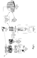
- Figure 1 is a block diagram illustrating some examples of elements that can be included in a system or method that uses a meter 104 with an electronic address 106 as a gateway (collectively the "system" 100).
- a building 102 is potentially any structure having a utility meter 104 with a fixed electronic address 106.
- Some buildings 102 are residential, such as detached single family homes, townhouses, condominiums, apartments, mobile homes, lofts, etc.
- Examples of non-residential buildings 102 include offices, warehouses, factories, stores, public areas, parks, remote water pumps, etc.
- the building 102 can house a variety of mobile and non-mobile devices (collectively "devices” 103) that can benefit from using the meter 104 as a gateway for communication between the building 102 and the outside world.
- devices can include general purpose computers such as tablet computers, laptop computers, desktop computers, and PDAs.
- Any "intelligent" appliance with an embedded computer capable of communicating with the meter 103 can be a device 104.
- the system 100 can flexibly accommodate future intelligent appliances, as well as a wide variety of different networking technologies and methodologies.
- more than one of the devices 103 will be connected to a network in the building 102. In other embodiments, there is no network of devices 103, but the devices 103 are capable of interacting with the meter 104.
- a meter 104 is a component connected to the building 102 that is operated and managed by a utility company. Examples of meters 104 can include electrical power meters, gas meters, and water meters. In the future, cable and satellite components may also server as meters 104. For a meter 104 to serve as a gateway for the flow of information in the system 100, the meter 104 should be addressable, (i.e. it should have an electronic address 106 such as an IP address).
- the meter 104 can be integrated into a nearby transformer to lower installation costs and improve the visual appeal of buildings 102.
- An electronic address 106 associated with the meter 104 allows the meter 104 to serve as an information gateway for the system 100. Potentially any unique identifier can serve as an electronic address 106, as long as it can be uniquely associated with the specific location where the meter is installed.
- a communication 108 is information exchanged between the meter 104 and a utility provider 110.
- the communication 108 can be transmitted over the same physical connection used by the utility provider 110 to provide the utility, such as an electrical power line used to provide electricity.
- the communication 108 can also be transmitted using satellites, earth relay stations, cellular telephone network, and network control centers. Any technology or combination of technologies that can be used to transmit information can be used by the system 100 to transfer information.
- a utility provider 110 is the company that provides the meter 104 to the building. In many embodiments of the system 100, the utility provider 110 operates the gateway functionality of the system 100. In other embodiments, an outside entity such as an application service provider (ASP) can be responsible for the aspects of the system 100 that do not directly relate to the providing of utility services to the building 102.
- ASP application service provider
- a server 112 is any device that is capable of storing information used to support the functionality of the system 100.
- One or more servers 112 will typically host one or more databases 114.
- the server 112 can be operated and managed by the utility provider 110, or those tasks can be performed by another entity such as an ASP.
- a database 114 is potentially any information technology methodology used to store information so that it can be accessed in the future.
- Databases 114 are typically relational databases, although object-oriented and hierarchical databases can also be used. Flat files, arrays, and other data structures can also be used to achieve the functionality of the database 114.
- Databases 114 are used by the system 100 to store information such as electronic addresses 106 associated with meters 104, as well as occupant and building information that is associated with the particular building 102 associated with the particular meter 104.
- Information relating to occupants of a building as well as to the building itself can be stored in one or more databases 114 as one or more occupant records 116.
- the variety of information that can be stored as occupant records 116 can vary as widely as the different ancillary services 120 (as identified above and below) that can be performed by the system 100.
- the occupant record 116 can include information relating to the structure, status, and functionality of those devices 103.
- Occupant information along with the corresponding electronic address 106 of the applicable meter 104 can be sent to a third party 118 for the purpose of providing services 120 that benefit either the building 102, the utility provider 104, and/or the third party 118.
- a third party 118 is any individual, organization, company, government entity, or non-profit organization 118 that is provided access to occupant information in order to perform the functionality of the system 100.
- the third party 118 could be the police department, the fire department, an ambulance, etc.
- An ancillary service 120 is any function, process, or advantage generated by the third party 118 that is influenced by the occupant information transmitted to the third party 118 by the system 100.
- Ancillary services 120 can also be referred to as services 120. Services 120 do not directly relate to providing of the utility to the building 102 by the utility provider 110.
- utility providers 110 are often best situated to possess up to date information relating to the occupants of a building 102. However, utility providers 110 typically have little motivation for storing and accessing up-to-date occupant records 116 using "addressable" meters 104 as gateways because utility providers 110 are not in the business of providing the ancillary services 120.
- the system 100 allows third parties 118 to benefit from the information library of the utility provider 110.
- third parties 118 typically provide the services 120 that are made possible by the system 100.
- the utility provider 110 could engage in the business and operations of what would otherwise be a third party 118.
- the system 100 anticipates that buildings 102, utility providers 110, and third parties 118 can each potentially benefit from the exchange of information made possible by the system 100.
- some embodiments of the system 100 may involve an application service provider ("ASP") 140 to maintain and operate the aspects of the system 100 that make information available to third parties 118.
- Utility providers 110 may not want to take on responsibilities that are not within the core competency of some utility providers 110.
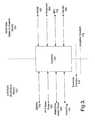
- FIG. 3 is a network diagram illustrating an example of a gateway 150 (e.g. the addressable 106 portion of the meter 104) between a LAN 152 and a WAN 154.
- a gateway 150 e.g. the addressable 106 portion of the meter 104
- LAN 152 e.g. the addressable 106 portion of the meter 104
- WAN 154 e.g. the Internet WAN 154
- a wide variety of different network connections can interact with the gateway 150.
- ZigBee 156 or some other form of wireless connectivity
- a KYZ meter pulse 158 or some other form of high quality shielded or unshielded signal wires
- a meter pulse 160 for water and/or gas flow information
- a home plug 162 or some other form of interactive network connectivity for various devices 103.
- PSTN public Switched Telephone Network
- Orbcomm Orbcomm line 164 or some other form of orbital network
- BPL Broadband over Powerline
- different services 120 can utilize a wide variety of different network connections. As indicated by the arrows at the bottom of the Figure, a downlink direction 170 is towards the building 102 and an uplink direction 172 points away from the building towards the outside world, i.e. where third parties 118 perform services 120 using the information made accessible by the system 100.
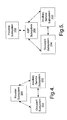
- Figure 4 is a block diagram illustrating an example of a subsystem-level view of the system 100.
- a provider subsystem 200 includes the infrastructural components controlled and operated by the utility provider 110, including the servers 112 and databases 114 used to store and access occupant records 116 that are associated with electronic addresses 106 which are in turn associated with meters 104 and buildings 102.
- the provider subsystem 200 also includes the mechanisms for communications 108 between the meter 104 and the utility provider 110.
- a service subsystem 202 includes the interactions of one or more third parties 118 as recipients of occupant information from the provider subsystem 200.
- the service subsystem 202 makes services 120 accessible to the system.
- An occupant subsystem 204 is the means by which occupants, their devices 103, and the buildings 102 inhabited by the occupants and devices 103 are made manifest to provider subsystem 200 or ancillary service subsystem 202. In addition to providing information to the system 100, the occupant subsystem 204 interacts with the services 120 made accessible by the services subsystem 202.
- Figure 5 is a block diagram illustrating an example of a subsystem-level view of the system 100 that includes an ASP subsystem 206.
- the ASP subsystem 206 serves as an intermediary between the provider subsystem 200 and the other subsystems.
- the embodiment illustrated in Figure 5 discloses an example of a utility provider 110 that wants to benefit from the system 100 and to make the functionality of the system 100 available to third parties 118 and to occupants without wanting to run the system 100 themselves.
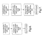
- Figure 6 is a flow chart diagram illustrating an example of a method for using a meter 104 as a gateway 150.
- an occupant record 116 is associated with the meter 104.
- a link is created between the meter 104 and a remote server 112 run by either the utility provider 110 or the ASP 140 acting on behalf of the utility provider 110.
- the information gateway 150 is ready for use, and the setup process ends.
- Figure 7 is a flow chart diagram illustrating an example of a method for using a meter 104 as a gateway 150 for ancillary services 120 provided by third parties 118.
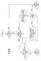
- Figure 8 is a flow chart diagram illustrating an example of a user authentication process.
- the authentication heuristic illustrated in Figure 8 is the sole method for determining whether or not an occupant is allowed to access a particular service 120 and the outcome of the heuristic is dispositive with respect to whether or not the occupant can access the service 120.
- occupant authentication can be performed as a "backup" to other forms of authentication, such as in the case of an online transaction. Failure to properly authenticate may merely result in a warning to the other party, or such failure may influence the transaction in other ways without necessarily prohibiting the transaction.
- the system 100 determines whether or not the residential supervisory and control gateway (RSCG) ID is available. If it is not, service is disallowed at 302.
- RSCG residential supervisory and control gateway
- the system 100 determines at 304 whether or not the access value for the service 120 is programmed into the device 103. If it is not, the service ID and the RSGC ID are sent to the third party 118 or the ASP 140 with an inquiry at 308 whether it is ok to program the device 104 for access. If at 308 it is not ok to provide for such access, service is disallowed at 302.
- the access information is programmed remotely by the ASP 140 or the third party 118 at 310. If the RSGC ID matches the programmed value at 312, service is allowed at 314. Otherwise, it is disallowed at 302.
- Services 120 are made accessible by the system 100 in a manner that is generally consistent with the process flow in Figure 1.
- a variety of services 120 by the system 100 could assist emergency response personnel in an emergency.
- Information relating to the occupants could be transmitted to the ambulance from the database 114 residing on the server 112.
- the lights at the building 102 could also be made to automatically flicker or flash, assisting the ambulance in finding the building 102.
- the occupants of the building 102 can be notified even when outside the building 102 if the temperature range within the building 102 exceeds certain ranges or if the heater and/or air conditioner ceases to function properly.
- a furnace or air conditioning failure can persist for hours without being detected if the occupants are not within the building 102 at the time of failure. By the time failure is detected, the building 102 can be extremely cold or warm, and the condition will only get worse before it is ultimately corrected. After the failure is corrected, the building 102 is returned to the desirable temperature, which often requires significant amounts of energy. By detecting failure early through remote means, power is saved and inconvenience minimized.
- the occupant of the building can be notified when the temperature exceeds the predefined range, which can be influenced by the time of day, day of the week, and season of the year. In some embodiments, the occupants can adjust the predefined temperature remotely over the Internet or some similar network.
- Monitoring can be performed remotely to determine whether a vacant property has become occupied. If an allegedly vacant building 102 is associated with a non-vacant electrical consumption profile, a message can be sent to the power company as well as to the owner of the building 102.
- Smart appliances and other devices 103 with data display and/or sound capability can communicate with the meter 104 using short range wireless or home plug communications.
- the electric meter 104 can relay the messages and replies to and/or from the sender.
- the provider 110 and/or ASP 140 can relay messages received from the Internet to occupants in the building 102.
- a diabetic may want to have blood sugar levels regularly transmitted to his or her doctor for the purpose of establishing a more natural insulin regimen.
- a heart patient may have regular blood pressure measurements sent to his or her cardiologist in order to look for patterns that can be used to help avoid any worsening of condition.
- the monitoring device 103 can be either hardwired to its sensors (such as a blood pressure cuff) or can utilize a wireless connection (such as a pulse rate watch). At predefined intervals, the monitoring device 103 can collect and store data from the sensors. The transmission time of the data can be influenced by whether or not a condition appears critical.
- An infrared detector can be used to indicate activity within a building for the purpose of elder care.
- the system 100 can provide a mechanism for care givers to have an indication that the person in question is going about their business normally. If something is wrong, the system 100 can transmit an early indication or warning about the particular symptom or condition.
- the system 100 can include a small module that can be plugged into a convenient outlet where the person being monitored would be expected to travel regularly.
- the module can include a low-cost PIR sensor that can detect the presence of the human body and a wired or wireless connection to the gateway 150. If the detector does not detect the presence of the person being monitored within a predetermined interval, such as 4 hours during the daytime and 9 hours at night, an alert could be sent to a caregiver or other appropriate agency. It is also possible to query the detector in order to determine that it is operating properly.
- the system 100 can be configured to detect the flushing of a toilet and reporting that information to a care provider or monitoring service.
- the system 100 can alert occupants when they are not at home that the sump pump is not working, and that the water level in a portion of the house is rising.
- a battery-operated water level detector device 103 can be installed with the sump.
- the device 103 can include a wireless connector to the gateway 150.
- a message can be sent to the home owner or a third party 118 monitoring service via the gateway 150.
- the water-level detector device 103 can be integrated into the sump pump itself and utilize the power of the line to communicate with the gateway 150.
- the sump pump includes a self diagnostic module that can detect failure or improper operation and communicate the status to the gateway 150 over power lines.
- Level detector devices 103 in communication with the gateway 150 can monitor food and water levels, notifying the occupants or temporary care givers in the case of unavailable occupants.
- Water sensor devices 103 in communication with the gateway 150 can monitor the environmental quality of drinking water.
- the monitor device 103 can look for levels of iron, hydrogen sulfide, e-coli bacteria, etc.
- Such sensors can be located at a well head for a group of buildings 102, and/or within individual buildings 102.
- a monitoring device 103 can be installed at a sewer lift station for a building 102. If a problem is detected, the gateway 150 can inform the occupant or the appropriate third party 118.
- the gateway 150 can be used as the primary network for security applications, or as a backup network in an instance where the primary network is not functional. Notification can be sent to third parties 118 such as the police as well as private security providers.
- the system 100 can confirm with third party 118 cable and satellite providers that the occupants in a building are authorized (e.g. they have paid for) the cable and/or satellite content being viewed.
- the system 100 can be configured to automatically prohibit fraudulent access, generate a warning, and/or report the fraud to the third party provider 118.
- the identity and location of occupants can be confirmed in online transactions by allowing the other party to request confirmation from the gateway 150.
- Access to cable and satellite content can be conditioned upon confirmation that access is warranted. Such confirmation can be provided through the gateway 150.
Abstract
Description
- The invention relates generally to systems and methods (collectively the "system") for using a utility meter. More specifically, the system uses an electronically addressable utility meter as a gateway for the exchange of information between the building and the outside world.
- Two trends in 21st century America seem difficult to ignore much less dispute. First, the demands of the modern economy have made people of all socio-economic backgrounds more mobile, and thus contact information has become more transitory. Employees seem to change jobs with increasing frequency. It is not uncommon for people to leave their town or even their state to pursue career advancement or to merely hold onto a job. Some neighbors seem to come and go so quickly that the traditional neighborhood relationships of the past seem quaint in 21st century America. The highly transitory nature of society makes it less likely that information such as phone numbers, addresses, and other publicly accessible contact information will be up to date. Moreover, a highly transitory society can leave an individual or entire families more isolated with respect to their neighborhoods in which they live. For example, if the neighbors to an elderly widow are less likely to invest the time to get to know their neighbors, it is also less likely that such neighbors would notice whether or not the elderly widow is incapacitated by a health problem within her own house and out of public sight.
- The second trend that is difficult to ignore much less dispute is the significance of e-commerce transactions. An increasing number of goods and services can be purchased online using the Internet or other forms of computer networks. The processing of such transactions in an accurate and non-fraudulent manner is made more difficult by the likelihood that publicly available contact information is out of date.
- The invention relates generally to systems and methods (collectively the "system") for using a utility meter. More specifically, the system uses an electronically addressable utility meter as a gateway for the exchange of information between the building and the outside world.
- By using the meter as a gateway, various ancillary services can be provided. Ancillary services can include but are not limited to, one or more of the following:
- transmitting meter information directly to the utility company;
- transmitting emergency alerts to occupants of a building;
- transmitting security alarms to third parties outside the building;
- detecting fraudulent access to media content;
- authenticating the identity of a purchaser in an online transaction;
- purchasing media content;
- monitoring an occupant subject to a home detention status;
- providing rapid occupant information to emergency response personnel;
- remotely setting and/or monitoring the thermostat in a building;
- remotely monitoring vacant properties;
- exchanging short messages;
- monitor medical condition monitoring devices;
- infrared human detection and network for reporting elderly care;
- toilet flush detection and network reporting;
- sump pump monitor with network reporting;
- animal food and water level detection;
- water condition monitoring;
- sewer condition monitoring; and
- exchange of information with devices within the building to devices and third parties outside the building.
- The system can be more fully understood upon reading the following detailed description in conjunction with the accompanying drawings.
-
- Figure 1 is a block diagram illustrating some examples of elements that can be included in the system
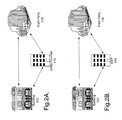
- Figure 2a is a relationship diagram illustrating an example of various interactions between different entities that can occur using the system.
- Figure 2b is a relationship diagram illustrating an example of various interactions between different entities that can occur using the system.
- Figure 3 is a network diagram illustrating an example of a gateway (e.g. the meter) between a LAN and a WAN.
- Figure 4 is a block diagram illustrating an example of a subsystem-level view of the system.
- Figure 5 is a block diagram illustrating an example of a subsystem-level view of the system.
- Figure 6 is a flow chart diagram illustrating an example of a method for using a meter as a gateway.
- Figure 7 is a flow chart diagram illustrating an example of a method for using a meter as a gateway for ancillary services provided by third parties.
- Figure 8 is a flow chart diagram illustrating an example of a user authentication process.
- The invention relates generally to systems and methods (collectively the "system") for using a utility meter. More specifically, the system uses an electronically addressable utility meter as a gateway for the exchange of information between the building and the outside world.
- The gateway can benefit the utility company, the occupants of the building, and third party service providers in a variety of different ways, including but not limited to:
- providing secure and location specific data connectivity to a building;
- emergency alerts to one or more buildings, such as homes, apartments, offices, or public areas;
- serving as backup communication networks for security applications;
- detecting fraudulent access to satellite television receivers and/or cable boxes;
- authenticating the identity of purchasers and sellers in online transactions;
- preventing fraud in online transactions;
- securely authorizing access to cable and satellite television content;
- monitoring home detention devices for use by parolees;
- providing occupant information in a timely manner for emergency response personnel;
- monitoring and/or setting a thermostat remotely;
- monitoring occupancy of vacant properties remotely;
- sending and/or receiving messages over utility lines;
- exchanging information between intelligent appliances and/or other devices in the building with applications and entities outside the building;
- monitoring medical devices within the building;
- infrared human detection with network reporting for care of the elderly and/or infirmed;
- toilet flush detection with network reporting;
- sump pump monitor with network reporting;
- animal food and water level detection;
- water condition monitor;
- water level (e.g. flooding) monitor; and
- sewer condition monitor.
- Figure 1 is a block diagram illustrating some examples of elements that can be included in a system or method that uses a
meter 104 with anelectronic address 106 as a gateway (collectively the "system" 100). - A
building 102 is potentially any structure having autility meter 104 with a fixedelectronic address 106. Somebuildings 102 are residential, such as detached single family homes, townhouses, condominiums, apartments, mobile homes, lofts, etc. Examples ofnon-residential buildings 102 include offices, warehouses, factories, stores, public areas, parks, remote water pumps, etc. - The
building 102 can house a variety of mobile and non-mobile devices (collectively "devices" 103) that can benefit from using themeter 104 as a gateway for communication between thebuilding 102 and the outside world. Examples of devices can include general purpose computers such as tablet computers, laptop computers, desktop computers, and PDAs. Any "intelligent" appliance with an embedded computer capable of communicating with themeter 103 can be adevice 104. Thesystem 100 can flexibly accommodate future intelligent appliances, as well as a wide variety of different networking technologies and methodologies. - In some embodiments, more than one of the
devices 103 will be connected to a network in thebuilding 102. In other embodiments, there is no network ofdevices 103, but thedevices 103 are capable of interacting with themeter 104. - A
meter 104 is a component connected to thebuilding 102 that is operated and managed by a utility company. Examples ofmeters 104 can include electrical power meters, gas meters, and water meters. In the future, cable and satellite components may also server asmeters 104. For ameter 104 to serve as a gateway for the flow of information in thesystem 100, themeter 104 should be addressable, (i.e. it should have anelectronic address 106 such as an IP address). - In some embodiments of the
system 100 where theutility provider 110 is an electrical power company and themeter 104 is an electrical power meter, themeter 104 can be integrated into a nearby transformer to lower installation costs and improve the visual appeal ofbuildings 102. - An
electronic address 106 associated with themeter 104 allows themeter 104 to serve as an information gateway for thesystem 100. Potentially any unique identifier can serve as anelectronic address 106, as long as it can be uniquely associated with the specific location where the meter is installed. - A
communication 108 is information exchanged between themeter 104 and autility provider 110. Thecommunication 108 can be transmitted over the same physical connection used by theutility provider 110 to provide the utility, such as an electrical power line used to provide electricity. Thecommunication 108 can also be transmitted using satellites, earth relay stations, cellular telephone network, and network control centers. Any technology or combination of technologies that can be used to transmit information can be used by thesystem 100 to transfer information. - A
utility provider 110 is the company that provides themeter 104 to the building. In many embodiments of thesystem 100, theutility provider 110 operates the gateway functionality of thesystem 100. In other embodiments, an outside entity such as an application service provider (ASP) can be responsible for the aspects of thesystem 100 that do not directly relate to the providing of utility services to thebuilding 102. - A
server 112 is any device that is capable of storing information used to support the functionality of thesystem 100. One ormore servers 112 will typically host one ormore databases 114. Theserver 112 can be operated and managed by theutility provider 110, or those tasks can be performed by another entity such as an ASP. - A
database 114 is potentially any information technology methodology used to store information so that it can be accessed in the future.Databases 114 are typically relational databases, although object-oriented and hierarchical databases can also be used. Flat files, arrays, and other data structures can also be used to achieve the functionality of thedatabase 114.Databases 114 are used by thesystem 100 to store information such aselectronic addresses 106 associated withmeters 104, as well as occupant and building information that is associated with theparticular building 102 associated with theparticular meter 104. - Information relating to occupants of a building as well as to the building itself (collectively "occupant information") can be stored in one or
more databases 114 as one or more occupant records 116. The variety of information that can be stored asoccupant records 116 can vary as widely as the different ancillary services 120 (as identified above and below) that can be performed by thesystem 100. For example, if thesystem 100 is being used to communicate with intelligent appliances in the building, then theoccupant record 116 can include information relating to the structure, status, and functionality of thosedevices 103. - Occupant information along with the corresponding
electronic address 106 of theapplicable meter 104 can be sent to athird party 118 for the purpose of providingservices 120 that benefit either thebuilding 102, theutility provider 104, and/or thethird party 118. - A
third party 118 is any individual, organization, company, government entity, ornon-profit organization 118 that is provided access to occupant information in order to perform the functionality of thesystem 100. For example, if thesystem 100 is configured to provide emergency response personnel with information relating to the occupants of thebuilding 102, thethird party 118 could be the police department, the fire department, an ambulance, etc. - An
ancillary service 120 is any function, process, or advantage generated by thethird party 118 that is influenced by the occupant information transmitted to thethird party 118 by thesystem 100.Ancillary services 120 can also be referred to asservices 120.Services 120 do not directly relate to providing of the utility to thebuilding 102 by theutility provider 110. - The potential variety of
different services 120 are discussed both above and below. - Because utilities are location specific,
utility providers 110 are often best situated to possess up to date information relating to the occupants of abuilding 102. However,utility providers 110 typically have little motivation for storing and accessing up-to-date occupant records 116 using "addressable"meters 104 as gateways becauseutility providers 110 are not in the business of providing theancillary services 120. Thesystem 100 allowsthird parties 118 to benefit from the information library of theutility provider 110. - As illustrated in Figures 2a and 2b,
third parties 118 typically provide theservices 120 that are made possible by thesystem 100. In some embodiments, theutility provider 110 could engage in the business and operations of what would otherwise be athird party 118. Thesystem 100 anticipates thatbuildings 102,utility providers 110, andthird parties 118 can each potentially benefit from the exchange of information made possible by thesystem 100. - As illustrated in Figure 2b, some embodiments of the
system 100 may involve an application service provider ("ASP") 140 to maintain and operate the aspects of thesystem 100 that make information available tothird parties 118.Utility providers 110 may not want to take on responsibilities that are not within the core competency of someutility providers 110. - Figure 3 is a network diagram illustrating an example of a gateway 150 (e.g. the addressable 106 portion of the meter 104) between a
LAN 152 and aWAN 154. A wide variety of different network connections can interact with thegateway 150. - The particular number of network connections and the characteristics of those connections will depend on the
services 120 being provided in the particular embodiment of thesystem 100. - On the side of the
gateway 150 in that runs from thebuilding 102 to themeter 104 in Figure 1, there is a: (1) ZigBee 156 or some other form of wireless connectivity; (2) aKYZ meter pulse 158 or some other form of high quality shielded or unshielded signal wires; (3) ameter pulse 160 for water and/or gas flow information; and (4) ahome plug 162 or some other form of interactive network connectivity forvarious devices 103. - On the side of the network to the outside of the
meter 104 with respect to thebuilding 102 are potential connections including: (1) a PSTN (public Switched Telephone Network) or some other form of telecommunication land line; (2) anOrbcomm line 164 or some other form of orbital network; (3) a BPL (Broadband over Powerline)line 166 or some other form of broadband and/or powerline connectivity; and (4) acellular connection 168. - In some embodiments of the
system 100,different services 120 can utilize a wide variety of different network connections. As indicated by the arrows at the bottom of the Figure, adownlink direction 170 is towards thebuilding 102 and anuplink direction 172 points away from the building towards the outside world, i.e. wherethird parties 118 performservices 120 using the information made accessible by thesystem 100. - Figure 4 is a block diagram illustrating an example of a subsystem-level view of the
system 100. - A
provider subsystem 200 includes the infrastructural components controlled and operated by theutility provider 110, including theservers 112 anddatabases 114 used to store andaccess occupant records 116 that are associated withelectronic addresses 106 which are in turn associated withmeters 104 andbuildings 102. Theprovider subsystem 200 also includes the mechanisms forcommunications 108 between themeter 104 and theutility provider 110. - A
service subsystem 202 includes the interactions of one or morethird parties 118 as recipients of occupant information from theprovider subsystem 200. Theservice subsystem 202 makesservices 120 accessible to the system. - An
occupant subsystem 204 is the means by which occupants, theirdevices 103, and thebuildings 102 inhabited by the occupants anddevices 103 are made manifest toprovider subsystem 200 orancillary service subsystem 202. In addition to providing information to thesystem 100, theoccupant subsystem 204 interacts with theservices 120 made accessible by theservices subsystem 202. - Figure 5 is a block diagram illustrating an example of a subsystem-level view of the
system 100 that includes anASP subsystem 206. As illustrated in the Figure, theASP subsystem 206 serves as an intermediary between theprovider subsystem 200 and the other subsystems. The embodiment illustrated in Figure 5 discloses an example of autility provider 110 that wants to benefit from thesystem 100 and to make the functionality of thesystem 100 available tothird parties 118 and to occupants without wanting to run thesystem 100 themselves. - Figure 6 is a flow chart diagram illustrating an example of a method for using a
meter 104 as agateway 150. - At 200, an
occupant record 116 is associated with themeter 104. - At 202, a link is created between the
meter 104 and aremote server 112 run by either theutility provider 110 or theASP 140 acting on behalf of theutility provider 110. Theinformation gateway 150 is ready for use, and the setup process ends. - Figure 7 is a flow chart diagram illustrating an example of a method for using a
meter 104 as agateway 150 forancillary services 120 provided bythird parties 118. - As discussed both above and below, a wide variety of
services 120 can be made accessible at 204. - Figure 8 is a flow chart diagram illustrating an example of a user authentication process. In some embodiments, the authentication heuristic illustrated in Figure 8 is the sole method for determining whether or not an occupant is allowed to access a
particular service 120 and the outcome of the heuristic is dispositive with respect to whether or not the occupant can access theservice 120. In other embodiments, occupant authentication can be performed as a "backup" to other forms of authentication, such as in the case of an online transaction. Failure to properly authenticate may merely result in a warning to the other party, or such failure may influence the transaction in other ways without necessarily prohibiting the transaction. - At 300, the
system 100 determines whether or not the residential supervisory and control gateway (RSCG) ID is available. If it is not, service is disallowed at 302. - If the ID is available, the
system 100 determines at 304 whether or not the access value for theservice 120 is programmed into thedevice 103. If it is not, the service ID and the RSGC ID are sent to thethird party 118 or theASP 140 with an inquiry at 308 whether it is ok to program thedevice 104 for access. If at 308 it is not ok to provide for such access, service is disallowed at 302. - Otherwise, the access information is programmed remotely by the
ASP 140 or thethird party 118 at 310. If the RSGC ID matches the programmed value at 312, service is allowed at 314. Otherwise, it is disallowed at 302. - There are a wide variety of
different services 120 that can either be made possible by using theaddressable meter 104 as agateway 150, or that can be enhanced significantly by using theaddressable meter 104 as agateway 150. Some examples are discussed both above and below.Services 120 are made accessible by thesystem 100 in a manner that is generally consistent with the process flow in Figure 1. - A variety of
services 120 by thesystem 100 could assist emergency response personnel in an emergency. Information relating to the occupants (including, potentially, medical information) could be transmitted to the ambulance from thedatabase 114 residing on theserver 112. The lights at thebuilding 102 could also be made to automatically flicker or flash, assisting the ambulance in finding thebuilding 102. - The occupants of the
building 102 can be notified even when outside thebuilding 102 if the temperature range within thebuilding 102 exceeds certain ranges or if the heater and/or air conditioner ceases to function properly. - A furnace or air conditioning failure can persist for hours without being detected if the occupants are not within the
building 102 at the time of failure. By the time failure is detected, thebuilding 102 can be extremely cold or warm, and the condition will only get worse before it is ultimately corrected. After the failure is corrected, thebuilding 102 is returned to the desirable temperature, which often requires significant amounts of energy. By detecting failure early through remote means, power is saved and inconvenience minimized. - The occupant of the building can be notified when the temperature exceeds the predefined range, which can be influenced by the time of day, day of the week, and season of the year. In some embodiments, the occupants can adjust the predefined temperature remotely over the Internet or some similar network.
- Monitoring can be performed remotely to determine whether a vacant property has become occupied. If an allegedly
vacant building 102 is associated with a non-vacant electrical consumption profile, a message can be sent to the power company as well as to the owner of thebuilding 102. - Smart appliances and
other devices 103 with data display and/or sound capability can communicate with themeter 104 using short range wireless or home plug communications. Theelectric meter 104 can relay the messages and replies to and/or from the sender. Theprovider 110 and/orASP 140 can relay messages received from the Internet to occupants in thebuilding 102. - There are many situations where it will be desirable to record various biometrics or vital sign measurements and regularly transmit the data to a health monitoring service for further processing. For example, a diabetic may want to have blood sugar levels regularly transmitted to his or her doctor for the purpose of establishing a more natural insulin regimen. Similarly, a heart patient may have regular blood pressure measurements sent to his or her cardiologist in order to look for patterns that can be used to help avoid any worsening of condition.
- The
monitoring device 103 can be either hardwired to its sensors (such as a blood pressure cuff) or can utilize a wireless connection (such as a pulse rate watch). At predefined intervals, themonitoring device 103 can collect and store data from the sensors. The transmission time of the data can be influenced by whether or not a condition appears critical. - An infrared detector can be used to indicate activity within a building for the purpose of elder care.
- Many elderly people live at home alone and generally care for themselves with only occasional visits from relatives and visiting nurses. However, following an injury such as from a fall or a stroke, the person may be unable to summon help and must instead wait for the next visitor before receiving medical assistance. Moreover, many care givers would like to provide more continuous care, but are hindered by time and distance. The
system 100 can provide a mechanism for care givers to have an indication that the person in question is going about their business normally. If something is wrong, thesystem 100 can transmit an early indication or warning about the particular symptom or condition. - The
system 100 can include a small module that can be plugged into a convenient outlet where the person being monitored would be expected to travel regularly. The module can include a low-cost PIR sensor that can detect the presence of the human body and a wired or wireless connection to thegateway 150. If the detector does not detect the presence of the person being monitored within a predetermined interval, such as 4 hours during the daytime and 9 hours at night, an alert could be sent to a caregiver or other appropriate agency. It is also possible to query the detector in order to determine that it is operating properly. - As part of monitoring a residence occupied by an elderly, infirm, or otherwise vulnerable occupant, the
system 100 can be configured to detect the flushing of a toilet and reporting that information to a care provider or monitoring service. - The
system 100 can alert occupants when they are not at home that the sump pump is not working, and that the water level in a portion of the house is rising. - Many times a home owner with a basement finds that his or her basement has flooded due to a sump pump failure, and that the failure has gone unnoticed for hours or even days. There are several different methods that can be used to detect flooding before it is severe.
- A battery-operated water
level detector device 103 can be installed with the sump. Thedevice 103 can include a wireless connector to thegateway 150. When water reaches the level of thedetector device 103, a message can be sent to the home owner or athird party 118 monitoring service via thegateway 150. - The water-
level detector device 103 can be integrated into the sump pump itself and utilize the power of the line to communicate with thegateway 150. - In some embodiments, the sump pump includes a self diagnostic module that can detect failure or improper operation and communicate the status to the
gateway 150 over power lines. - In many large animal farms as well as in family homes, animals can be fed and given access to water using automated means. Equipment failure may take several days or even weeks to detect.
Level detector devices 103 in communication with thegateway 150 can monitor food and water levels, notifying the occupants or temporary care givers in the case of unavailable occupants. -
Water sensor devices 103 in communication with thegateway 150 can monitor the environmental quality of drinking water. Themonitor device 103 can look for levels of iron, hydrogen sulfide, e-coli bacteria, etc. Such sensors can be located at a well head for a group ofbuildings 102, and/or withinindividual buildings 102. - Grease, solvents, and other harmful materials often illegally enter municipal sewer systems. If the material enters the sanitary sewer, the result can be harmful to the process of breaking down the wastes and lead to reduced water treatment capacity. If the foreign material enters the storm sewer system, it can enter a surface water feature such as a lake, stream, or river where it can cause environmental damage. A
monitoring device 103 can be installed at a sewer lift station for abuilding 102. If a problem is detected, thegateway 150 can inform the occupant or the appropriatethird party 118. - The
gateway 150 can be used as the primary network for security applications, or as a backup network in an instance where the primary network is not functional. Notification can be sent tothird parties 118 such as the police as well as private security providers. - The
system 100 can confirm withthird party 118 cable and satellite providers that the occupants in a building are authorized (e.g. they have paid for) the cable and/or satellite content being viewed. Thesystem 100 can be configured to automatically prohibit fraudulent access, generate a warning, and/or report the fraud to thethird party provider 118. - The identity and location of occupants can be confirmed in online transactions by allowing the other party to request confirmation from the
gateway 150. - Access to cable and satellite content can be conditioned upon confirmation that access is warranted. Such confirmation can be provided through the
gateway 150. - In accordance with the provisions of the patent statutes, the principles and modes of operation of this invention have been explained and illustrated in preferred embodiments. However, it must be understood that this invention may be practiced otherwise than is specifically explained and illustrated without departing from its spirit or scope.
Claims (20)
- A gateway for managing the flow of information to and from a building (102), comprising:an outside line, wherein said outline line facilitates the delivery of a utility and of a communication (108); anda meter (104), wherein said meter (104) provides for an electronic address (106);a database (114), wherein said database (114) is remote from the building (102), and wherein said database (114) provides for storing of said electronic address (106) and an occupant record (116) associated with said electronic address (106);
wherein said outside line connects a utility provider (110) to said meter (104); and
wherein said communication (108) is transmitted to a third party (118). - The gateway of claim 1, wherein said communication influences an ancillary service (120), said ancillary service (120) including at least one of: (a) an emergency alert; (b) a rapid identification for emergency response personnel; (c) a monitoring of vacant property; (d) authenticating an online purchaser; (e) detecting fraudulent media access; (f) authorizing media access; (g) exchanging messages with devices in the building; and (h) monitoring an occupant.
- The gateway of claim 1, further comprising a server (112), wherein said database (114) is accessible from said server (112), wherein said server (112) is not located within the building (102), wherein said gateway provides for exchanging a plurality of communications between said server (112) and said meter (104).
- The gateway of claim 3, further comprising a satellite, wherein said satellite provides for exchanging said communications (108) between said server (112) and said meter (104).
- The gateway of claim 1, wherein said communication (108) is sent to a plurality of residences.
- The gateway of claim 1, wherein said occupant record (116) and electronic address (106) is transmitted to a plurality of third party providers (118) responsible for providing a plurality of ancillary services (120).
- The gateway of claim 1, wherein the building (102) is a single family home, wherein the meter (104) is an electrical power meter, wherein the utility is electrical power, and wherein said communication (108) relates to devices (103) within the single family home.
- The gateway of claim 1, further comprising a WAN (154) and a LAN (152), wherein said WAN (154) resides between said meter (104) and said database (114), and wherein said LAN (152) resides between said meter (104) and the building (102).
- A system for providing an ancillary service (120) using a utility meter (104), comprising:a provider subsystem (200), wherein said provider subsystem (200) provides for a meter (104), a server (112), a database (114), and a link (108) between said server (112) and said meter (104), wherein said database (114) resides on said server (112), wherein said meter (104) is associated with an electronic address (106), and wherein said database (114) provides for storing said electronic address (106) and an occupant record (116) associated with said electronic address (106); anda service subsystem (202), wherein said service subsystem (202) provides for at least one of a plurality of ancillary services (120).
- A method for providing a utility and a communications link to a home, comprising:associating an occupant record (116) with an electronic address (106) in a meter (104) utilized for measuring the delivery of said utility to said home, andcreating a link between the meter (104) and a server (112),wherein said link (108) provides for exchanging a plurality of communications (108) between the meter (104) and the server (112), wherein the link (108) further provides for the transmission of a utility to the home.
- The method of claim 10, further comprising selectively providing a third party (118) with access to the occupant record (116) in furtherance of an ancillary service (120).
- The method of claim 10, further comprising authenticating a purchaser in an online transaction using the occupant record (116).
- The method of claim 10, further comprising:receiving data from a device (103) within the home, wherein the data is received by the meter (104); andtransmitting the data to a third party (118), wherein the data is transmitted by the meter (104).
- The method of claim 10, further comprising:monitoring a health status of an occupant of the home.
- The method of claim 10, further comprising:transmitting an internal environmental instruction to the home.
- The method of claim 10, further comprising:monitoring the home, wherein the home is vacant.
- The method of claim 10, further comprising:sending an emergency alert to the home.
- The method of claim 10, further comprising:authorizing access to media content using the communication (108).
- The method of claim 10, further comprising:using a communication (108) to exchange a message between an occupant of the home and a service provider (120).
- The method of claim 10, further comprising:detecting at least one of: (a) an animal food level; or (b) a water level.
Applications Claiming Priority (2)
| Application Number | Priority Date | Filing Date | Title |
|---|---|---|---|
| US60431804P | 2004-08-25 | 2004-08-25 | |
| US11/183,602 US20060045105A1 (en) | 2004-08-25 | 2005-07-18 | System and method for using a utility meter |
Publications (1)
| Publication Number | Publication Date |
|---|---|
| EP1631009A1 true EP1631009A1 (en) | 2006-03-01 |
Family
ID=34979173
Family Applications (1)
| Application Number | Title | Priority Date | Filing Date |
|---|---|---|---|
| EP05076820A Withdrawn EP1631009A1 (en) | 2004-08-25 | 2005-08-05 | System and method for using a utility meter |
Country Status (2)
| Country | Link |
|---|---|
| US (1) | US20060045105A1 (en) |
| EP (1) | EP1631009A1 (en) |
Cited By (2)
| Publication number | Priority date | Publication date | Assignee | Title |
|---|---|---|---|---|
| WO2007090225A1 (en) * | 2006-02-06 | 2007-08-16 | Uhs Systems Pty Ltd | Versatile utility gateway |
| WO2008097453A1 (en) * | 2007-02-02 | 2008-08-14 | Silver Spring Networks, Inc. | Method and system of providing ip-based packet communications with in-premise devices in a utility network |
Families Citing this family (58)
| Publication number | Priority date | Publication date | Assignee | Title |
|---|---|---|---|---|
| US7248158B2 (en) * | 2000-04-14 | 2007-07-24 | Current Technologies, Llc | Automated meter reading power line communication system and method |
| US6998962B2 (en) | 2000-04-14 | 2006-02-14 | Current Technologies, Llc | Power line communication apparatus and method of using the same |
| EP1371219A4 (en) * | 2001-02-14 | 2006-06-21 | Current Tech Llc | Data communication over a power line |
| US7436321B2 (en) * | 2002-12-10 | 2008-10-14 | Current Technologies, Llc | Power line communication system with automated meter reading |
| US7224272B2 (en) * | 2002-12-10 | 2007-05-29 | Current Technologies, Llc | Power line repeater system and method |
| US7321291B2 (en) * | 2004-10-26 | 2008-01-22 | Current Technologies, Llc | Power line communications system and method of operating the same |
| US7856032B2 (en) * | 2005-04-04 | 2010-12-21 | Current Technologies, Llc | Multi-function modem device |
| US7265664B2 (en) * | 2005-04-04 | 2007-09-04 | Current Technologies, Llc | Power line communications system and method |
| US7627453B2 (en) | 2005-04-26 | 2009-12-01 | Current Communications Services, Llc | Power distribution network performance data presentation system and method |
| US7259657B2 (en) * | 2005-06-21 | 2007-08-21 | Current Technologies, Llc | Multi-subnet power line communications system and method |
| US7358808B2 (en) * | 2005-06-21 | 2008-04-15 | Current Technologies, Llc | Method and device for amplification of data signals over power lines |
| US7769149B2 (en) * | 2006-01-09 | 2010-08-03 | Current Communications Services, Llc | Automated utility data services system and method |
| US20080012724A1 (en) * | 2006-01-30 | 2008-01-17 | Corcoran Kevin F | Power line communications module and method |
| US7852207B2 (en) * | 2006-02-14 | 2010-12-14 | Current Technologies, Llc | Method for establishing power line communication link |
| US7796025B2 (en) | 2006-03-27 | 2010-09-14 | Current Technologies, Llc | Power line communication device and method |
| US7764943B2 (en) * | 2006-03-27 | 2010-07-27 | Current Technologies, Llc | Overhead and underground power line communication system and method using a bypass |
| US8073705B2 (en) * | 2006-04-14 | 2011-12-06 | Blu Trend, Llc | Systems and methods for the prevention of extended utility theft |
| US7467092B2 (en) * | 2006-04-14 | 2008-12-16 | Blu Trend, Llc | Systems and methods for the prevention of extended utility theft |
| US9105181B2 (en) | 2006-06-08 | 2015-08-11 | Mueller International, Llc | Systems and methods for generating power through the flow of water |
| CA2932858C (en) * | 2006-06-08 | 2018-09-25 | Mueller International, Llc | Systems and methods for remote utility metering and meter monitoring |
| US8279080B2 (en) * | 2006-06-08 | 2012-10-02 | Fairfax County Water Authority | Systems and methods for remote utility metering and meter monitoring |
| US20070297425A1 (en) * | 2006-06-23 | 2007-12-27 | George Chirco | Systems and methods for establishing a network over a substation dc/ac circuit |
| US8359278B2 (en) * | 2006-10-25 | 2013-01-22 | IndentityTruth, Inc. | Identity protection |
| US20080103798A1 (en) * | 2006-10-25 | 2008-05-01 | Domenikos Steven D | Identity Protection |
| US7859646B2 (en) * | 2007-01-24 | 2010-12-28 | Adelphi University | Interferometric method for improving the resolution of a lithographic system |
| US7908116B2 (en) * | 2007-08-03 | 2011-03-15 | Ecofactor, Inc. | System and method for using a network of thermostats as tool to verify peak demand reduction |
| US8019567B2 (en) | 2007-09-17 | 2011-09-13 | Ecofactor, Inc. | System and method for evaluating changes in the efficiency of an HVAC system |
| US7848900B2 (en) | 2008-09-16 | 2010-12-07 | Ecofactor, Inc. | System and method for calculating the thermal mass of a building |
| US20090125351A1 (en) * | 2007-11-08 | 2009-05-14 | Davis Jr Robert G | System and Method for Establishing Communications with an Electronic Meter |
| US20090234803A1 (en) * | 2008-03-11 | 2009-09-17 | Continental Electrical Construction Company, Llc | Keyword search of business information system |
| US8010237B2 (en) | 2008-07-07 | 2011-08-30 | Ecofactor, Inc. | System and method for using ramped setpoint temperature variation with networked thermostats to improve efficiency |
| US8180492B2 (en) | 2008-07-14 | 2012-05-15 | Ecofactor, Inc. | System and method for using a networked electronic device as an occupancy sensor for an energy management system |
| US20100262393A1 (en) * | 2009-04-08 | 2010-10-14 | Manu Sharma | System and Method for Determining a Phase Conductor Supplying Power to a Device |
| US20100262395A1 (en) * | 2009-04-08 | 2010-10-14 | Manu Sharma | System and Method for Determining a Phase Conductor Supplying Power to a Device |
| US8498753B2 (en) * | 2009-05-08 | 2013-07-30 | Ecofactor, Inc. | System, method and apparatus for just-in-time conditioning using a thermostat |
| US8740100B2 (en) | 2009-05-11 | 2014-06-03 | Ecofactor, Inc. | System, method and apparatus for dynamically variable compressor delay in thermostat to reduce energy consumption |
| US8596550B2 (en) | 2009-05-12 | 2013-12-03 | Ecofactor, Inc. | System, method and apparatus for identifying manual inputs to and adaptive programming of a thermostat |
| US20110202293A1 (en) * | 2010-02-15 | 2011-08-18 | General Electric Company | Diagnostics using sub-metering device |
| US9652802B1 (en) | 2010-03-24 | 2017-05-16 | Consumerinfo.Com, Inc. | Indirect monitoring and reporting of a user's credit data |
| US8556188B2 (en) | 2010-05-26 | 2013-10-15 | Ecofactor, Inc. | System and method for using a mobile electronic device to optimize an energy management system |
| US10584890B2 (en) | 2010-05-26 | 2020-03-10 | Ecofactor, Inc. | System and method for using a mobile electronic device to optimize an energy management system |
| US8090477B1 (en) | 2010-08-20 | 2012-01-03 | Ecofactor, Inc. | System and method for optimizing use of plug-in air conditioners and portable heaters |
| WO2012112781A1 (en) | 2011-02-18 | 2012-08-23 | Csidentity Corporation | System and methods for identifying compromised personally identifiable information on the internet |
| US9631833B2 (en) * | 2011-06-17 | 2017-04-25 | Emerson Electric Co. | Climate control systems, and methods relating thereto |
| US8819793B2 (en) | 2011-09-20 | 2014-08-26 | Csidentity Corporation | Systems and methods for secure and efficient enrollment into a federation which utilizes a biometric repository |
| US11030562B1 (en) | 2011-10-31 | 2021-06-08 | Consumerinfo.Com, Inc. | Pre-data breach monitoring |
| US9870597B2 (en) * | 2011-11-18 | 2018-01-16 | Conservice, Llc | Systems and methods allowing multi-family property owners to consolidate retail electric provider charges with landlord provided utilities and services |
| US10048706B2 (en) | 2012-06-14 | 2018-08-14 | Ecofactor, Inc. | System and method for optimizing use of individual HVAC units in multi-unit chiller-based systems |
| US9157434B2 (en) * | 2013-01-22 | 2015-10-13 | PumpSpy Technology, LLC | Sump pump system with automated system monitoring and data collection |
| US8812387B1 (en) | 2013-03-14 | 2014-08-19 | Csidentity Corporation | System and method for identifying related credit inquiries |
| US9794355B2 (en) | 2014-04-08 | 2017-10-17 | Samsung Electronics Co., Ltd. | Systems and methods for adaptive notification networks |
| US9696360B2 (en) | 2014-06-04 | 2017-07-04 | Rf Group Llc | Sump/ejector pump monitor and sump/ejector pump failure warning system |
| US10339527B1 (en) | 2014-10-31 | 2019-07-02 | Experian Information Solutions, Inc. | System and architecture for electronic fraud detection |
| US11151468B1 (en) | 2015-07-02 | 2021-10-19 | Experian Information Solutions, Inc. | Behavior analysis using distributed representations of event data |
| US11022124B2 (en) * | 2017-04-10 | 2021-06-01 | Logical Concepts, Inc. | Whole home water appliance system |
| US11187223B2 (en) | 2017-04-10 | 2021-11-30 | Logical Concepts, Inc. | Home flood prevention appliance system |
| US10699028B1 (en) | 2017-09-28 | 2020-06-30 | Csidentity Corporation | Identity security architecture systems and methods |
| US10896472B1 (en) | 2017-11-14 | 2021-01-19 | Csidentity Corporation | Security and identity verification system and architecture |
Citations (3)
| Publication number | Priority date | Publication date | Assignee | Title |
|---|---|---|---|---|
| US5699276A (en) * | 1995-12-15 | 1997-12-16 | Roos; Charles E. | Utility meter providing an interface between a digital network and home electronics |
| US20040059585A1 (en) * | 2002-09-24 | 2004-03-25 | Poweronedata Corporation | Utility power meter, metering system and method |
| US20040113810A1 (en) * | 2002-06-28 | 2004-06-17 | Mason Robert T. | Data collector for an automated meter reading system |
Family Cites Families (4)
| Publication number | Priority date | Publication date | Assignee | Title |
|---|---|---|---|---|
| US5010568A (en) * | 1989-04-04 | 1991-04-23 | Sparton Corporation | Remote meter reading method and apparatus |
| US6062166A (en) * | 1999-02-01 | 2000-05-16 | Macrina; John L. | Pet feeding system |
| JP3996428B2 (en) * | 2001-12-25 | 2007-10-24 | 松下電器産業株式会社 | Abnormality detection device and abnormality detection system |
| US7117051B2 (en) * | 2004-03-15 | 2006-10-03 | Tmio, Llc | Appliance communication system and method |
-
2005
- 2005-07-18 US US11/183,602 patent/US20060045105A1/en not_active Abandoned
- 2005-08-05 EP EP05076820A patent/EP1631009A1/en not_active Withdrawn
Patent Citations (3)
| Publication number | Priority date | Publication date | Assignee | Title |
|---|---|---|---|---|
| US5699276A (en) * | 1995-12-15 | 1997-12-16 | Roos; Charles E. | Utility meter providing an interface between a digital network and home electronics |
| US20040113810A1 (en) * | 2002-06-28 | 2004-06-17 | Mason Robert T. | Data collector for an automated meter reading system |
| US20040059585A1 (en) * | 2002-09-24 | 2004-03-25 | Poweronedata Corporation | Utility power meter, metering system and method |
Cited By (8)
| Publication number | Priority date | Publication date | Assignee | Title |
|---|---|---|---|---|
| WO2007090225A1 (en) * | 2006-02-06 | 2007-08-16 | Uhs Systems Pty Ltd | Versatile utility gateway |
| WO2008097453A1 (en) * | 2007-02-02 | 2008-08-14 | Silver Spring Networks, Inc. | Method and system of providing ip-based packet communications with in-premise devices in a utility network |
| US8364846B2 (en) | 2007-02-02 | 2013-01-29 | Silver Spring Networks, Inc. | Method and system of providing IP-based packet communications with in-premisis devices in a utility network |
| US8429295B2 (en) | 2007-02-02 | 2013-04-23 | Silver Spring Networks, Inc. | Method and system of providing IP-based packet communications in a utility network |
| US8489716B2 (en) | 2007-02-02 | 2013-07-16 | Silver Spring Networks, Inc. | Method and system of providing network addresses to in-premise devices in a utility network |
| US8892774B2 (en) | 2007-02-02 | 2014-11-18 | Silver Spring Networks, Inc. | Method and system of providing IP-based packet communications in a utility network |
| US9094458B2 (en) | 2007-02-02 | 2015-07-28 | Silver Spring Networks, Inc. | Method and system of providing network addresses to in-premise devices in a utility network |
| US9178716B2 (en) | 2007-02-02 | 2015-11-03 | Silver Spring Networks, Inc. | Method and system of providing IP-based packet communications in a utility network |
Also Published As
| Publication number | Publication date |
|---|---|
| US20060045105A1 (en) | 2006-03-02 |
Similar Documents
| Publication | Publication Date | Title |
|---|---|---|
| EP1631009A1 (en) | System and method for using a utility meter | |
| US11363107B2 (en) | Location monitoring via a gateway | |
| US10539713B2 (en) | Location monitoring via a gateway | |
| US10977736B1 (en) | Determining risks related to activities on insured properties using informatic sensor data | |
| US20060244589A1 (en) | Method and system for an insurance auditor to audit a premise alarm system | |
| US20190064391A1 (en) | Remote Location Monitoring | |
| TWI237466B (en) | A method for supervising and supporting customer service rendered by service providers using a communication network, and the communication network system for realizing the same | |
| JP6183893B2 (en) | Resident safety confirmation system | |
| US20080243391A1 (en) | Information Managing/Providing System and Method | |
| KR20070084019A (en) | A system of devices comprising a plurality of sensor devices communicating with a central gateway device | |
| KR101609999B1 (en) | Solitude Oldster monitoring system using using remote inspection device | |
| JP4466469B2 (en) | Information terminal, earthquake information acquisition method, and program thereof | |
| JP2017021496A (en) | Anti-heat stroke alarming system for apartment house intended for elderly residents | |
| JP5909832B1 (en) | Centralized water meter reading device with safety monitoring function | |
| KR101329257B1 (en) | Apparatus for safety management of apartment house resident and method thereof | |
| JP4386849B2 (en) | Homeless patrol system and meter reading terminal | |
| KR101433785B1 (en) | Method and system for providing combined error-correction based auto meter reading service and safety-related service | |
| KR100971845B1 (en) | Fundamental information on aspects of daily life integrated information control system and control method | |
| JP2002109667A (en) | Management device for life watching | |
| JPH0769995B2 (en) | A system that determines the residents' life changes based on the water usage | |
| JP7465461B2 (en) | Watch Program | |
| KR102407150B1 (en) | Emergency notification service system and method for Resident in House | |
| KR101228007B1 (en) | System for providing living convenience by using a home aqua-grid system and method for the same | |
| CN113674112A (en) | Community data convergence and fusion access all-in-one machine | |
| JP2006268348A (en) | Residence safety supporting apparatus |
Legal Events
| Date | Code | Title | Description |
|---|---|---|---|
| PUAI | Public reference made under article 153(3) epc to a published international application that has entered the european phase |
Free format text: ORIGINAL CODE: 0009012 |
|
| AK | Designated contracting states |
Kind code of ref document: A1 Designated state(s): AT BE BG CH CY CZ DE DK EE ES FI FR GB GR HU IE IS IT LI LT LU LV MC NL PL PT RO SE SI SK TR |
|
| AX | Request for extension of the european patent |
Extension state: AL BA HR MK YU |
|
| 17P | Request for examination filed |
Effective date: 20060901 |
|
| 17Q | First examination report despatched |
Effective date: 20061009 |
|
| AKX | Designation fees paid |
Designated state(s): AT BE BG CH CY CZ DE DK EE ES FI FR GB GR HU IE IS IT LI LT LU LV MC NL PL PT RO SE SI SK TR |
|
| STAA | Information on the status of an ep patent application or granted ep patent |
Free format text: STATUS: THE APPLICATION IS DEEMED TO BE WITHDRAWN |
|
| 18D | Application deemed to be withdrawn |
Effective date: 20080923 |