EP1878659A2 - Wing with negative dihedral for pulling a load - Google Patents
Wing with negative dihedral for pulling a load Download PDFInfo
- Publication number
- EP1878659A2 EP1878659A2 EP07005414A EP07005414A EP1878659A2 EP 1878659 A2 EP1878659 A2 EP 1878659A2 EP 07005414 A EP07005414 A EP 07005414A EP 07005414 A EP07005414 A EP 07005414A EP 1878659 A2 EP1878659 A2 EP 1878659A2
- Authority
- EP
- European Patent Office
- Prior art keywords
- wing
- propulsive
- leading edge
- line
- range
- Prior art date
- Legal status (The legal status is an assumption and is not a legal conclusion. Google has not performed a legal analysis and makes no representation as to the accuracy of the status listed.)
- Withdrawn
Links
Images


Classifications
-
- B—PERFORMING OPERATIONS; TRANSPORTING
- B64—AIRCRAFT; AVIATION; COSMONAUTICS
- B64C—AEROPLANES; HELICOPTERS
- B64C31/00—Aircraft intended to be sustained without power plant; Powered hang-glider-type aircraft; Microlight-type aircraft
- B64C31/06—Kites
-
- B—PERFORMING OPERATIONS; TRANSPORTING
- B63—SHIPS OR OTHER WATERBORNE VESSELS; RELATED EQUIPMENT
- B63H—MARINE PROPULSION OR STEERING
- B63H8/00—Sail or rigging arrangements specially adapted for water sports boards, e.g. for windsurfing or kitesurfing
- B63H8/10—Kite-sails; Kite-wings; Control thereof; Safety means therefor
- B63H8/12—Kites with inflatable closed compartments
-
- B—PERFORMING OPERATIONS; TRANSPORTING
- B64—AIRCRAFT; AVIATION; COSMONAUTICS
- B64C—AEROPLANES; HELICOPTERS
- B64C31/00—Aircraft intended to be sustained without power plant; Powered hang-glider-type aircraft; Microlight-type aircraft
- B64C31/06—Kites
- B64C2031/065—Kites of inflatable wing type
Definitions
- the present invention relates to a propulsive wing with negative dihedral traction of a load, of the type comprising a flexible wing defined between two lateral ends connected to each other, at the front by a leading edge and at the rear by a trailing edge, the wing having, between these two lateral ends, a propulsive median range bordered on both sides by two steering surfaces, the wing comprising at least one suspension member of the load in the vicinity of each lateral end; and auxiliary support means adapted to flatten the propulsive central range in the vicinity of the leading edge, during flight.
- propulsive wings sometimes called “kites”, for pulling or lifting a load.
- Such propulsive wings are used in some sports, including water sports.
- Such is the case for example of the sport designated in English by "kite boarding", where a user has feet connected to a board allowing him to slide on the surface of the water, while the body of the user is connected to a propulsive wing, allowing him to move.
- Most of the propulsive wings currently in use consist of a pronounced negative dihedral soft canopy connected to the user by lines attached to the lateral ends of the wing, or along the leading edge, i.e. that the lateral ends of the wing are located at a level below the median range of the wing during use.
- the wing then has, from the front, an approximately semi-circular shape turned downward, shape dictated by the wind, the aerodynamic forces, and not by the rigidity of the structure.
- a propulsive wing of this type is described for example in the document EP-0202271 .
- This wing has the general shape of a spherical spindle.
- a wing performance gain can be achieved by flattening the wing in its median range. This flattening also increases the safety of the user, in the case where the wing is equipped with more than two flight lines, allowing an opening of the profile and a greater reduction of the power of the wing, when this- it is subject to wind gusts or when the user loses control of the wing. Indeed, the front line or lines being set higher on the leading edge than the spherical flange wings, the rotation of the wing profile is greater when releasing the rear lines.
- the wing provided with such a spar has a flattened leading edge, while the trailing edge tends to keep its lobed shape.
- the two rudder lanes bordering the median beach of the wing are too inclined towards each other towards the rear of the wing, creating a significant drag which reduces the speed of the wing.
- Such a wing has in particular been proposed under the brand GAASTRA.
- a wing marketed under the trademark FLEX has a set of suspension forming flanges secured only along the leading edge of the wing.
- a rigid spar further ensures the median flattening of the leading edge.
- the wing has a general shape of ellipsoidal spindle with convex leading edge and trailing edge. There is, in flight, a slight but modest flattening of the leading edge while the trailing edge is not at all flattened and retains a lobed shape. As for the previous wing, this arrangement creates a significant drag.
- Another proposed solution is to equip the wing on most of the surface of the wing, lines forming flanges. These lines are regularly distributed on the surface of the wing in rows extending from the leading edge to the trailing edge. They are taken directly or indirectly on the user. The multitude of lines connected to the wing increases the aerodynamic drag and creates lobes in the wing between each row of flanges, so that the performance of the wing is lessened.
- the object of the invention is to propose a propulsive wing whose propulsive median range is relatively flat, both at the leading edge and at the trailing edge, and is perfectly tensioned, without degradation of aerodynamic performance.
- the subject of the invention is a propulsive wing with a negative dihedron for pulling a load, of the aforementioned type, characterized in that it comprises rear lines connected to the suspension members arranged at the lateral ends of the wing.
- the auxiliary means for maintaining the propulsive median range comprise at least one front line connected at one end to the propulsive central range in the vicinity of the leading edge and capable of being connected to the load at its other end, the or each front line comprising a set of lines applied to the propulsive central range at points distributed along the length of the leading edge, at least one sliding line being slidably engaged in a guide secured to the leading edge, end of the sliding line being secured to a rear line.
- the propulsive wing 10 shown in Figures 1 to 4 is intended for the traction of a load, such as an athlete whose feet are secured to a board.
- the propulsive wing comprises a flexible wing 12 defined between two lateral ends 14A, 14B.
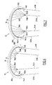
- the wing 12 has, between its two lateral ends 14A, 14B, a median propulsive range 16 bordered on both sides by two steering surfaces 18A, 18B.
- the wing 12 has at the front a leading edge 20 and at the rear a trailing edge 22 visible in Figure 2. They both extend from one end 14A to the other 14B. The wing 12 extends between the two edges 20, 22 to define a continuous left surface.
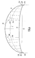
- the propulsive wing is negative dihedron, that is to say that it has, seen from the front, an arched shape whose concavity is turned towards the suspended load.
- the two steering ranges 18A, 18B are located at a lower level than that of the propulsive range 16.
- the width of the sail decreases symmetrically from the median range of the wing to the lateral ends 14A. 14B.
- the wing 12 is supported by an inflated main coil 24 extending from one lateral end 14A to the other lateral end 14B.
- This sausage has a generally flattened crescent moon shape. Its diameter is gradually decreasing from its median range to its ends.
- the wing is secured to the front following the inflated pudding 24.
- Stringers 26 are evenly distributed along the length of the main coil 24 and extend from the leading edge 20 to the trailing edge 22 of the wing. They each consist of an inflated pudding. These tubes are connected, at their front end, to the main coil 24.
- the wing 12 is secured to the longitudinal members 26 over their entire length, these beams being located below the wing, that is to say on the side of the load to tow.
- the propulsive wing comprises a member 30A, 30B for suspending the load to be towed.
- This member is constituted for example by a ring for anchoring a hanger, or by a strap sewn at the end of the wing.
- the profiles that is to say the longitudinal sections of the wing 12 may have any known aerodynamic shape, they do not require a particular aerodynamic shape for the wing to operate. They are advantageously concave, that is to say that their curvature has no point of inflection, the curvature is always oriented in the same direction.
- the trailing edge has, in top view, a generally arcuate shape towards the rear or a generally concave shape.
- the leading edge 20 is alone associated with auxiliary support means 32 adapted to flatten the median range of the leading edge 20, during the flight. These holding means 32 are applied in the vicinity of the leading edge.
- the expression in the vicinity of the leading edge means along the leading edge or between the leading edge and the line of the thrust centers of the wing, the holding means being thus forward the center of thrust of each section by considering the direction of advance of the wing.
- Figure 4 is shown, by a line C, the position of the center of thrust associated with each (profile or section) of the wing according to the length of the wing from one lateral end 14A to the other 14B.
- the arched shape towards the rear of the wing is obtained when the center of thrust is all the more forward that the section considered is close to the longitudinal axis of the wing.
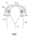
- the thrust center of a section of the steering ranges 18A, 18B is behind the center of thrust of a section of the propulsive mid-range 16 of the wing.
- the auxiliary support means 32 capable of flattening the front part of the median wing area during the flight comprise, for example, two front lines 34A, 34B each comprising a bundle of three converging lines 36A. , 36B connected together by a common end. The other end of each line is connected at a point in the vicinity of the leading edge 20.
- the various connection points of the lines 36A, 36B on the leading edge 20 are distributed along the length of its middle portion.
- the lines 36A, 36B of each bundle connect together to form a front line 34A, 34B, itself secured to the load to tow.
- the length of the various lines 36A, 36B is chosen so that, by pulling on the free end of the front lines 34A, 34B, the lines connected in the median range of the wing, ensure a greater retention of the wing than the lines arranged at the ends of this median range, thus ensuring a flattening of the leading edge of the wing in the propulsive middle range thereof.
- the auxiliary holding means 32 comprise not lines but a rigid spar attached to the leading edge or in the vicinity of the leading edge, thus ensuring a maintenance of the leading edge in the median range of the leading edge. wing following a generally rectilinear profile.
- the load is connected to the lateral ends 14A, 14B by two additional rear lines 40A, 40B secured to the suspension members 30A, 30B and is connected to the front of the range median by at least one line.
- auxiliary support means 32 on the sole vicinity of the leading edge is sufficient to ensure a flattening of the wing in the middle range of the leading edge.
- the wing is solicited by a lift force extending generally perpendicular to the surface of the wing.
- the control surfaces 18A, 18B are thus subjected to opposing lift forces F A , F B.
- These forces are applied on the median trailing edge range denoted 60 in FIG. 4.
- This median range 60 is held taut by the action of opposing lift forces F A , F B applied to the steering pads 18A, 18B. This tension leads to a flattening of the median range of the trailing edge, simply because of the backward shifting of the steering ranges related to the overall concave trailing edge.
- the leading edge 22 is maintained flattened in its median range by the auxiliary holding means, and the propulsive rear part in the vicinity of the trailing edge is also flattened by the action of opposing lift forces applied to the With the rudder lobes set back, the entire propulsive mid-range 16 of the sails is kept flat, although auxiliary means of support are applied only in the vicinity of the leading edge.
- the uniform flattening of the propulsive mid-range of the wing allows the steering surfaces to be kept approximately parallel to each other, allowing a good flow of air around the wing and avoiding too much drag. of the wing.
- the propulsive median range 16 being devoid of auxiliary support means, except in the vicinity of its leading edge 20, the wing has good aerodynamic qualities, due to the very great regularity of its surface.
- the aerodynamic elongation of the wing is greater than 3.
- the aerodynamic elongation is equal to the square of the wingspan divided by the surface of the wing.
- the wingspan is arbitrarily chosen as that of the wing deflated flat and the surface is the developed surface of the wing.
- the curvature of the trailing edge 22 is reversed only in the immediate vicinity of its ends over a length of a few tens of centimeters, in a region denoted 62.
- the curvature of the trailing edge 22 is reversed only in the immediate vicinity of the median axis of the wing to form a median tail 64 with a width of some tens of centimeters.
- the trailing edge has a generally concave shape thus allowing a flattening of the trailing edge in the propulsive median range, even if, locally, this trailing edge is not concave.
- the wing comprises only a front line disposed in a central position in the vicinity of the leading edge and two rear lines.
- the lines 36A, 36B are evenly distributed along the entire length of the median edge of the leading edge. They are connected to each other by a connecting line 72.
- a single front center line 74 is secured to the connecting line 72 in the median longitudinal plane of the wing, that is to say to the right of the central portion of the leading edge.
- control surfaces 18A, 18B are also equipped according to the leading edge 20 of lines 76A, 76B distributed to the ends from the leading edge. These lines are connected to each other and to the lines 36A, 36B by the extension on either side of the connecting line 72.
- the lines 76A, 76B and the ends of the connecting line 72 are connected to the rear lines 40A, 40B.
- the lines 36A, 36B end in beams to the front lines 34A, 34B. These lines are five in number. Furthermore, one or more lines 80A, 80B lead to the rear lines 40A, 40B. These lines 80A, 80B leading to the rear lines are linked at their other end to the leading edge 20 near its ends, that is to say near the lateral ends 14A, 14B of the wing.
- five lines 36A, 36B end by beams to the front lines 34A, 34B.
- an additional line 90A, 90B forming a hanger is engaged in a pulley 92A, 92B forming a guide which is fixed on the leading edge 20.
- This hanger 90A, 90B connects the front line 34A, 34B to the rear line 40A, 40B arranged on the same side.
- pulleys 92A, 92B are fixed on the leading edge 20 between the lines 36A, 36B connected to the front lines and the lines 80A, 80B connected to the rear lines when such lines connected to the rear lines exist.
- pulleys 92A, 92B are themselves carried by associated pulleys 94A, 94B. These pulleys 94A, 94B are slidably engaged on a loop 96A, 96B formed by a deformable strand whose ends are connected to the leading edge 20 at remote points.
- the lines 90A, 90B are connected at one end to the rear lines 40A, 40B and, at their other end, they end on a single front line 34.
- the pulleys 92A, 92B and 94A, 94B move along the length of the loops 96A, 96B, while the lines 90A, 90B slide in the pulleys 92A, 92B, allowing a distribution balanced forces taken by the lines 90A, 90B between the front and rear lines.
- An arrangement as described in Figures 6, 7 and 8 can be implemented with any type of wing and in particular with a wing whose trailing edge is not concave.
- the four lines 34A, 34B, 40A and 40B or the three lines 74, 40A, 40B can end at the same point to the load to be towed, the rear lines being adjusted in length to direct the wing.
- the two front lines are fixed together and the two rear lines are fixed on a bar, or the four lines are fixed on a bar, the two before passing in a pulley located lower than the bar, etc ....
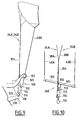
- the device 100 comprises a generally rectilinear control bar 102 intended to be held at arm's length by the user.
- the rear lines 40A, 40B secured to the lateral ends of the wing 14A, 14B are connected to the ends of the bar 102.
- the lower ends of the front lines 34A, 34B ensuring the maintenance of the leading edge 20 of the wing are connected to one another and are extended by a common traction line 104 whose other end is secured in 105 in the median range of the bar 102.
- the common traction line 104 is slidably mounted through a ring 106 integral with the bar 102 in its central range.
- a first pulley 110 is engaged on the traction line 104 and is held in a lower loop of this line between the connection point 105 and the ring 106.
- the axis of the pulley 110 is integral with the end of a return strand 112 whose other end is secured to the common traction line 104 in the portion between the ring 106 and the connecting end to the front lines 34A, 34B.
- a second pulley 114 is engaged on the return strand 112 in a lower loop thereof.
- the axis of the pulley 114 is equipped with a loop 116 for attaching the operating device to a harness 118 equipped with a hook 120 carried by the user or the load to be towed.
- the displacement of the control bar 102 along the length of the common traction line 104 secured to the harness makes it possible to ensure the control of the wing and in particular its inclination with respect to the horizontal, because of the modification of the relative position. in height of the median range of the leading edge and the lateral extremities of the wing.
- control bar 102 tilting the control bar 102 to the right or to the left makes it possible to direct the wing by action of the control surfaces 18A, 18B.
Abstract
Description
La présente invention concerne une aile propulsive à dièdre négatif de traction d'une charge, du type comportant une voilure souple définie entre deux extrémités latérales reliées entre elles, à l'avant par un bord d'attaque et, à l'arrière par un bord de fuite, la voilure présentant, entre ces deux extrémités latérales, une plage médiane propulsive bordée de part et d'autre par deux plages de gouverne, l'aile comportant au moins un organe de suspension de la charge au voisinage de chaque extrémité latérale et des moyens auxiliaires de maintien propres à aplatir la plage médiane propulsive au voisinage du bord d'attaque, lors du vol.The present invention relates to a propulsive wing with negative dihedral traction of a load, of the type comprising a flexible wing defined between two lateral ends connected to each other, at the front by a leading edge and at the rear by a trailing edge, the wing having, between these two lateral ends, a propulsive median range bordered on both sides by two steering surfaces, the wing comprising at least one suspension member of the load in the vicinity of each lateral end; and auxiliary support means adapted to flatten the propulsive central range in the vicinity of the leading edge, during flight.
Il est connu d'utiliser des ailes propulsives, parfois appelées "cerfs-volants", pour la traction ou la sustentation d'une charge. De telles ailes propulsives sont utilisées dans certains sports de glisse, notamment des sports aquatiques. Tel est le cas par exemple du sport désigné en anglais par "kite boarding", où un utilisateur a les pieds reliés à une planche lui permettant de glisser à la surface de l'eau, alors que le corps de l'utilisateur est relié à une aile propulsive, lui permettant de se déplacer.It is known to use propulsive wings, sometimes called "kites", for pulling or lifting a load. Such propulsive wings are used in some sports, including water sports. Such is the case for example of the sport designated in English by "kite boarding", where a user has feet connected to a board allowing him to slide on the surface of the water, while the body of the user is connected to a propulsive wing, allowing him to move.
La plupart des ailes propulsives utilisées actuellement sont constituées d'une voilure souple à dièdre négatif prononcé reliée à l'utilisateur par des lignes fixées aux extrémités latérales de l'aile, ou le long du bord d'attaque, c'est-à-dire que les extrémités latérales de l'aile sont situées à un niveau inférieur à la plage médiane de l'aile lors de son utilisation. L'aile a alors, de face, une forme approximativement demi-circulaire tournée vers le bas, forme dictée par le vent, les forces aérodynamiques, et non par la rigidité de la structure.Most of the propulsive wings currently in use consist of a pronounced negative dihedral soft canopy connected to the user by lines attached to the lateral ends of the wing, or along the leading edge, i.e. that the lateral ends of the wing are located at a level below the median range of the wing during use. The wing then has, from the front, an approximately semi-circular shape turned downward, shape dictated by the wind, the aerodynamic forces, and not by the rigidity of the structure.
Une aile propulsive de ce type est décrite par exemple dans le document
Il est généralement admis qu'un gain de performances de l'aile peut être obtenu en aplatissant la voilure dans sa plage médiane. Cet aplatissement accroît également la sécurité de l'utilisateur, dans le cas ou l'aile est équipée de plus de deux lignes de vol, en permettant une ouverture du profil et une réduction plus importante de la puissance de l'aile, lorsque celle-ci est soumise à des rafales de vent ou lorsque l'utilisateur perd le contrôle de l'aile. En effet, la ou les lignes avant étant fixées plus haut sur le bord d'attaque que sur les ailes en fuseau sphérique, la rotation du profil de l'aile est plus importante lorsqu'on relâche les lignes arrière.It is generally accepted that a wing performance gain can be achieved by flattening the wing in its median range. This flattening also increases the safety of the user, in the case where the wing is equipped with more than two flight lines, allowing an opening of the profile and a greater reduction of the power of the wing, when this- it is subject to wind gusts or when the user loses control of the wing. Indeed, the front line or lines being set higher on the leading edge than the spherical flange wings, the rotation of the wing profile is greater when releasing the rear lines.
Afin d'assurer un tel aplatissement de la plage médiane de l'aile, il a été proposé de munir la plage médiane du bord d'attaque de l'aile d'un espar rectiligne assurant l'aplatissement du bord d'attaque de l'aile.In order to ensure such a flattening of the median range of the wing, it has been proposed to provide the median range of the leading edge of the wing of a rectilinear spar for flattening the leading edge of the wing. 'wing.
On constate qu'en vol, l'aile munie d'un tel espar présente un bord d'attaque aplati, alors que le bord de fuite tend à garder sa forme lobée. Il en résulte que les deux plages de gouverne bordant la plage médiane de l'aile se trouvent trop inclinées l'une vers l'autre vers l'arrière de l'aile, créant une traînée importante qui réduit la vitesse de l'aile. Une telle aile a notamment été proposée sous la marque GAASTRA.It is found that in flight, the wing provided with such a spar has a flattened leading edge, while the trailing edge tends to keep its lobed shape. As a result, the two rudder lanes bordering the median beach of the wing are too inclined towards each other towards the rear of the wing, creating a significant drag which reduces the speed of the wing. Such a wing has in particular been proposed under the brand GAASTRA.
Par ailleurs, une aile commercialisée sous la marque FLEX présente un ensemble de suspentes formant brides solidarisées seulement suivant le bord d'attaque de l'aile. Un espar rigide assure de plus l'aplatissement médian du bord d'attaque. L'aile a une forme générale de fuseau ellipsoïdal avec un bord d'attaque et un bord de fuite convexes. On constate, en vol, un léger mais modeste aplatissement du bord d'attaque alors que le bord de fuite n'est pas du tout aplati et conserve une forme lobée. Comme pour l'aile précédente, cet agencement crée une traînée importante.Furthermore, a wing marketed under the trademark FLEX has a set of suspension forming flanges secured only along the leading edge of the wing. A rigid spar further ensures the median flattening of the leading edge. The wing has a general shape of ellipsoidal spindle with convex leading edge and trailing edge. There is, in flight, a slight but modest flattening of the leading edge while the trailing edge is not at all flattened and retains a lobed shape. As for the previous wing, this arrangement creates a significant drag.
Une autre solution proposée consiste à équiper l'aile sur l'essentiel de la surface de la voilure, de suspentes formant brides. Ces suspentes sont régulièrement réparties sur la surface de la voilure suivant des rangées s'étendant du bord d'attaque au bord de fuite. Elles sont reprises directement ou indirectement sur l'utilisateur. La multitude de suspentes reliées à la voilure augmente la traînée aérodynamique et crée dans la voilure des lobes entre chaque rangée de brides, de sorte que les performances de l'aile sont amoindries.Another proposed solution is to equip the wing on most of the surface of the wing, lines forming flanges. These lines are regularly distributed on the surface of the wing in rows extending from the leading edge to the trailing edge. They are taken directly or indirectly on the user. The multitude of lines connected to the wing increases the aerodynamic drag and creates lobes in the wing between each row of flanges, so that the performance of the wing is lessened.
L'invention a pour but de proposer une aile propulsive dont la plage médiane propulsive est relativement plate, aussi bien au niveau du bord d'attaque que du bord de fuite, et est parfaitement tendue, sans dégradation des performances aérodynamiques.
A cet effet, l'invention a pour objet une aile propulsive à dièdre négatif de traction d'une charge, du type précité, caractérisée en ce qu'elle comporte des lignes arrière reliées aux organes de suspension disposées aux extrémités latérales de l'aile, et en ce que les moyens auxiliaires de maintien de la plage médiane propulsive comportent au moins une ligne avant reliée par une extrémité à la plage médiane propulsive au voisinage du bord d'attaque et propre à être reliée à la charge à son autre extrémité, la ou chaque ligne avant comportant un ensemble de suspentes appliquées à la plage médiane propulsive en des points répartis suivant la longueur du bord d'attaque, au moins une suspente coulissante étant engagée de manière coulissante dans un guide solidaire du bord d'attaque, l'extrémité de la suspente coulissante étant solidarisée à une ligne arrière.The object of the invention is to propose a propulsive wing whose propulsive median range is relatively flat, both at the leading edge and at the trailing edge, and is perfectly tensioned, without degradation of aerodynamic performance.
For this purpose, the subject of the invention is a propulsive wing with a negative dihedron for pulling a load, of the aforementioned type, characterized in that it comprises rear lines connected to the suspension members arranged at the lateral ends of the wing. , and in that the auxiliary means for maintaining the propulsive median range comprise at least one front line connected at one end to the propulsive central range in the vicinity of the leading edge and capable of being connected to the load at its other end, the or each front line comprising a set of lines applied to the propulsive central range at points distributed along the length of the leading edge, at least one sliding line being slidably engaged in a guide secured to the leading edge, end of the sliding line being secured to a rear line.
Suivant des modes particuliers de réalisation, l'aile propulsive comporte l'une ou plusieurs des caractéristiques suivantes :
- le bord de fuite de l'aile est généralement concave,
- la voilure présente, en vol, vue de dessus, une forme générale arquée vers le bord de fuite ;
- la plage médiane est dépourvue, excepté au voisinage du bord d'attaque de tout moyen auxiliaire de maintien propre à aplatir, en vol, la plage médiane propulsive ;
- l'allongement aérodynamique de l'aile est supérieur à 3 ;
- le centre de poussée de chaque section des plages de gouverne est en arrière du centre de poussée de chaque section de la plage médiane propulsive ;
- la ou chaque ligne comporte un ensemble de suspentes reprises à une extrémité sur la charge à tracter et dont les autres extrémités sont liées à la plage médiane propulsive en étant réparties suivant la longueur du bord d'attaque ;
- les moyens auxiliaires de maintien de la plage médiane propulsive au voisinage du bord d'attaque comportent un espar de rigidification solidarisé suivant le bord d'attaque ;
- la ligne des centres de poussée des sections de la voilure en vol d'une extrémité latérale à l'autre décrit la forme d'une courbe dont le centre de courbure en tout point est situé du côté du bord de fuite ;
- elle comporte des lignes arrière reliées aux organes de suspension disposés aux extrémités latérales de l'aile, les moyens auxiliaires de maintien de la plage médiane propulsive comportant au moins une ligne avant reliée par une extrémité à la plage médiane propulsive au voisinage du bord d'attaque et propre à être reliée à la charge à son autre extrémité, la ou chaque ligne avant comportant un ensemble de suspentes appliquées à la plage médiane propulsive en des points répartis suivant la longueur du bord d'attaque, au moins une suspente coulissante étant engagée de manière coulissante dans un guide solidaire du bord d'attaque, l'extrémité de la suspente coulissante étant solidarisée à une ligne arrière ;
- le guide est supporté de manière coulissante sur une boucle déformable liée en deux points distants du bord d'attaque ;
- elle comporte des lignes arrière reliées aux organes de suspension disposés aux extrémités latérales de l'aile, les moyens auxiliaires de maintien de la plage médiane propulsive comportant au moins une suspente reliée, à une extrémité, au bord d'attaque et, à son autre extrémité, à une ligne arrière ;
- elle comporte un dispositif de manoeuvre comprenant une barre de commande dont les extrémités sont reliées aux extrémités latérales de la voilure par des lignes arrière et au moins une ligne de traction reliée à la voilure en avant des lignes arrière par au moins une ligne avant, laquelle ligne de traction comporte des moyens de liaison au corps de l'utilisateur, lesquels moyens de liaison comportent au moins une poulie engagée dans une boucle de la ou de chaque ligne de traction dont l'extrémité est solidarisée à la barre de commande, la poulie comportant des moyens de liaison de son axe au corps de l'utilisateur ; et
- les moyens de liaison de l'axe de la poulie au corps de l'utilisateur comportent une poulie complémentaire engagée dans une boucle d'un brin de rappel dont une extrémité est fixée à l'axe de la poulie et dont l'autre extrémité est fixée à la ou à chaque ligne de traction, la poulie complémentaire comportant des moyens de liaison de son axe au corps de l'utilisateur.
- the trailing edge of the wing is generally concave,
- the wing presents, in flight, seen from above, a general shape arched towards the trailing edge;
- the median range is devoid, except in the vicinity of the leading edge of any auxiliary support means adapted to flatten, in flight, the propulsive median range;
- the aerodynamic elongation of the wing is greater than 3;
- the center of thrust of each section of the steering ranges is behind the center of thrust of each section of the propulsive median range;
- the or each line comprises a set of lines taken at one end on the load to be towed and whose other ends are related to the propulsive median range being distributed along the length of the leading edge;
- the auxiliary means for maintaining the propulsive median range in the vicinity of the leading edge comprise a stiffening spar secured to the leading edge;
- the line of the centers of pressure of wing sections in flight from one lateral end to the other describes the shape of a curve whose center of curvature at any point is situated on the side of the trailing edge;
- it comprises rear lines connected to the suspension members arranged at the lateral ends of the wing, the auxiliary means for maintaining the propulsive median range comprising at least one front line connected by one end to the propulsive central range in the vicinity of the edge of the wing; attack and adapted to be connected to the load at its other end, the or each front line having a set of lines applied to the propulsive central range at points distributed along the length of the leading edge, at least one sliding line being engaged slidably in a guide secured to the leading edge, the end of the sliding line being secured to a rear line;
- the guide is slidably supported on a deformable loop bonded at two points remote from the leading edge;
- it comprises rear lines connected to the suspension members arranged at the lateral ends of the wing, the auxiliary means for maintaining the propulsive median range comprising at least one suspension connected at one end to the leading edge and at its other end, to a back line;
- it comprises an operating device comprising a control bar whose ends are connected to the lateral ends of the wing by rear lines and at least one traction line connected to the wing in front of the rear lines by at least one front line, which traction line comprises means of connection to the body of the user, which connecting means comprise at least one pulley engaged in a loop of the or each traction line whose end is secured to the control bar, the pulley having means for connecting its axis to the body of the user; and
- the means for connecting the axis of the pulley to the body of the user comprise a complementary pulley engaged in a loop of a return strand whose one end is fixed to the axis of the pulley and whose other end is attached to the or each traction line, the complementary pulley having means for connecting its axis to the body of the user.
L'invention sera mieux comprise à la lecture de la description qui va suivre, donnée uniquement à titre d'exemple et faite en se référant aux dessins, sur lesquels :
- la figure 1 est une vue de face d'une aile propulsive, représentée en vol ;
- la figure 2 est une vue en perspective de l'aile de la figure 1 représentée en vol ;
- La figure 3 est une vue de côté de l'aile des figures 1 et 2, représentée en vol ;
- la figure 4 est une vue de dessus en plan de l'aile des figures précédentes, c'est-à-dire en projection à plat ;
- les figures 4A et 4B sont des vues identiques à celle de la figure 4 de variantes de réalisation de la forme de l'aile ;
- la figure 5 est une vue de face d'une variante de réalisation d'une aile ;
- les figures 6, 7 et 8 sont des vues de face de variantes de réalisation de l'aile propulsive ;
- la figure 9 est une vue schématique en perspective d'un dispositif de manoeuvre de l'aile propulsive, l'aile étant représentée avec une taille réduite ; et
- la figure 10 est une vue en perspective du dispositif de manoeuvre de la figure 9.
- Figure 1 is a front view of a propulsive wing, shown in flight;
- Figure 2 is a perspective view of the wing of Figure 1 shown in flight;
- Figure 3 is a side view of the wing of Figures 1 and 2, shown in flight;
- Figure 4 is a top plan view of the wing of the preceding figures, that is to say in flat projection;
- FIGS. 4A and 4B are views identical to that of FIG. 4 of variant embodiments of the shape of the wing;
- Figure 5 is a front view of an alternative embodiment of a wing;
- Figures 6, 7 and 8 are front views of alternative embodiments of the propulsive wing;
- Figure 9 is a schematic perspective view of a drive device of the propulsive wing, the wing being shown with a reduced size; and
- FIG. 10 is a perspective view of the operating device of FIG. 9.
L'aile propulsive 10 représentée sur les figures 1 à 4 est destinée à la traction d'une charge, telle qu'un sportif dont les pieds sont solidarisés sur une planche. L'aile propulsive comporte une voilure souple 12 définie entre deux extrémités latérales 14A, 14B. La voilure 12 présente, entre ses deux extrémités latérales 14A, 14B, une plage médiane propulsive 16 bordée de part et d'autre par deux plages de gouverne 18A, 18B.The
La voilure 12 présente à l'avant un bord d'attaque 20 et à l'arrière un bord de fuite 22 visibles sur la figure 2. Ils s'étendent tous deux d'une extrémité latérale 14A à l'autre 14B. La voilure 12 s'étend entre les deux bords 20, 22 pour définir une surface gauche continue.The
L'aile propulsive est à dièdre négatif, c'est-à-dire qu'elle présente, vue de face, une forme arquée dont la concavité est tournée vers la charge suspendue.The propulsive wing is negative dihedron, that is to say that it has, seen from the front, an arched shape whose concavity is turned towards the suspended load.
Plus précisément, les deux plages de gouverne 18A, 18B sont situées à un niveau inférieur à celui de la plage propulsive 16.Specifically, the two steering ranges 18A, 18B are located at a lower level than that of the
Comme illustré sur les figures 3 et 4, la largeur de la voile, mesurée longitudinalement entre le bord d'attaque 20 et le bord de fuite 22, décroît de manière symétrique depuis la plage médiane de l'aile jusqu'aux extrémités latérales 14A, 14B. Suivant le bord d'attaque de l'aile, la voilure 12 est supportée par un boudin principal gonflé 24 s'étendant d'une extrémité latérale 14A à l'autre extrémité latérale 14B. Ce boudin présente globalement une forme de croissant de lune aplati. Son diamètre est progressivement décroissant de sa plage médiane vers ses extrémités. La voilure est solidarisée à l'avant suivant le boudin gonflé 24.As illustrated in FIGS. 3 and 4, the width of the sail, measured longitudinally between the
Des longerons 26 sont répartis régulièrement suivant la longueur du boudin principal 24 et s'étendent du bord d'attaque 20 au bord de fuite 22 de l'aile. Ils sont constitués chacun d'un boudin gonflé. Ces boudins sont reliés, à leur extrémité avant, au boudin principal 24. La voilure 12 est solidarisée aux longerons 26 sur toute leur longueur, ces longerons étant situés au-dessous de la voilure, c'est-à-dire du côté de la charge à tracter.
A chacune des extrémités latérales, l'aile propulsive comporte un organe 30A, 30B de suspension de la charge à tracter. Cet organe est constitué par exemple d'un anneau pour l'ancrage d'une suspente, ou encore par une sangle cousue à l'extrémité de la voilure.At each of the lateral ends, the propulsive wing comprises a
Les profils, c'est-à-dire les sections longitudinales de la voilure 12 peuvent avoir toute forme aérodynamique connue, ils ne nécessitent pas une forme aérodynamique particulière pour que l'aile fonctionne. Ils sont avantageusement concaves, c'est-à-dire que leur courbure ne comporte pas de point d'inflexion, la courbure étant toujours orientée dans le même sens.The profiles, that is to say the longitudinal sections of the
Le bord de fuite présente, en vue de dessus, une forme générale arquée vers l'arrière ou encore une forme généralement concave.The trailing edge has, in top view, a generally arcuate shape towards the rear or a generally concave shape.
Le bord d'attaque 20 est seul associé à des moyens auxiliaires de maintien 32 propres à aplatir la plage médiane du bord d'attaque 20, lors du vol. Ces moyens de maintien 32 sont appliqués au voisinage du bord d'attaque.The leading
Au sens du présent document, l'expression au voisinage du bord d'attaque signifie suivant le bord d'attaque ou entre le bord d'attaque et la ligne des centres de poussée de l'aile, les moyens de maintien étant ainsi en avant du centre de poussée de chaque section en considérant le sens d'avancement de l'aile.For the purposes of this document, the expression in the vicinity of the leading edge means along the leading edge or between the leading edge and the line of the thrust centers of the wing, the holding means being thus forward the center of thrust of each section by considering the direction of advance of the wing.
Sur la figure 4 est représentée, par une ligne C, la position du centre de poussée associé à chaque (profil ou section) de la voilure suivant la longueur de la voilure d'une extrémité latérale 14A à l'autre 14B.In Figure 4 is shown, by a line C, the position of the center of thrust associated with each (profile or section) of the wing according to the length of the wing from one
La forme arquée vers l'arrière de la voilure est obtenue lorsque le centre de poussée est d'autant plus en avant que la section considérée est proche de l'axe longitudinal de l'aile. En particulier, le centre de poussée d'une section des plages de gouverne 18A, 18B est en arrière du centre de poussée d'une section de la plage médiane propulsive 16 de l'aile.The arched shape towards the rear of the wing is obtained when the center of thrust is all the more forward that the section considered is close to the longitudinal axis of the wing. In particular, the thrust center of a section of the steering ranges 18A, 18B is behind the center of thrust of a section of the propulsive mid-range 16 of the wing.
Comme illustré sur les figures 1 et 3, les moyens auxiliaires 32 de maintien propres à aplatir la partie avant de la plage médiane de l'aile lors du vol comportent par exemple deux lignes avant 34A, 34B comportant chacune un faisceau de trois suspentes convergentes 36A, 36B reliées ensemble par une extrémité commune. L'autre extrémité de chaque suspente est reliée en un point au voisinage du bord d'attaque 20. Les différents points de liaison des suspentes 36A, 36B sur le bord d'attaque 20 sont répartis suivant la longueur de sa partie médiane.As illustrated in FIGS. 1 and 3, the auxiliary support means 32 capable of flattening the front part of the median wing area during the flight comprise, for example, two
Les suspentes 36A, 36B de chaque faisceau se relient ensemble pour former une ligne avant 34A, 34B, elle-même solidarisée à la charge à tracter.The
La longueur des différentes suspentes 36A, 36B est choisie de sorte que, par traction sur l'extrémité libre des lignes avant 34A, 34B, les suspentes reliées dans la plage médiane de la voilure, assurent une retenue plus importante de la voilure que les suspentes disposées aux extrémités de cette plage médiane, assurant ainsi un aplatissement du bord d'attaque de la voilure dans la plage médiane propulsive de celle-ci.The length of the
En variante, les moyens auxiliaires de maintien 32 comportent non pas des suspentes mais un espar rigide rapporté sur le bord d'attaque ou au voisinage du bord d'attaque, assurant ainsi un maintien du bord d'attaque dans la plage médiane de l'aile suivant un profil généralement rectiligne.As a variant, the auxiliary holding means 32 comprise not lines but a rigid spar attached to the leading edge or in the vicinity of the leading edge, thus ensuring a maintenance of the leading edge in the median range of the leading edge. wing following a generally rectilinear profile.
Pour assurer la traction de la charge, et comme connu en soi, la charge est reliée aux extrémités latérales 14A, 14B par deux lignes supplémentaires arrière 40A, 40B solidarisées aux organes de suspension 30A, 30B et est reliée à l'avant de la plage médiane par au moins une ligne.To ensure the traction of the load, and as known per se, the load is connected to the lateral ends 14A, 14B by two additional
Avec une telle aile, on comprend que la présence des moyens auxiliaires de maintien 32 sur le seul voisinage du bord d'attaque suffise à assurer un aplatissement de la voilure dans la plage médiane du bord d'attaque.With such a wing, it is understood that the presence of auxiliary support means 32 on the sole vicinity of the leading edge is sufficient to ensure a flattening of the wing in the middle range of the leading edge.
En outre, lors du vol, la voilure est sollicitée par une force de portance s'étendant généralement perpendiculairement à la surface de la voilure. Les plages de gouverne 18A, 18B sont ainsi soumises à des forces de portance opposées FA, FB. Ces forces s'appliquent sur la plage médiane du bord de fuite notée 60 sur la figure 4. Cette plage médiane 60 se trouve maintenue tendue par l'action des forces de portance FA, FB opposées appliquées sur les plages de gouverne 18A, 18B. Cette tension conduit à un aplatissement de la plage médiane du bord de fuite, du seul fait du déport vers l'arrière des plages de gouverne lié au bord de fuite globalement concave.In addition, during flight, the wing is solicited by a lift force extending generally perpendicular to the surface of the wing. The control surfaces 18A, 18B are thus subjected to opposing lift forces F A , F B. These forces are applied on the median trailing edge range denoted 60 in FIG. 4. This
Dans la mesure où le bord d'attaque 22 est maintenu aplati dans sa plage médiane par les moyens auxiliaires de maintien, et que la partie arrière propulsive au voisinage du bord de fuite est elle aussi aplatie par action des forces de portance opposées appliquées sur les plages de gouverne placées en arrière, toute la plage médiane propulsive 16 de la voilure se trouve maintenue aplatie, bien que des moyens auxiliaires de maintien soient appliqués seulement au voisinage du bord d'attaque.Insofar as the leading
L'aplatissement homogène de la plage médiane propulsive de la voilure permet que les plages de gouverne soient maintenues approximativement parallèles l'une à l'autre, permettant un bon écoulement du flux d'air autour de l'aile et évitant une traînée trop importante de l'aile.The uniform flattening of the propulsive mid-range of the wing allows the steering surfaces to be kept approximately parallel to each other, allowing a good flow of air around the wing and avoiding too much drag. of the wing.
De plus, la plage médiane propulsive 16 étant dépourvue de moyens auxiliaires de maintien, sauf au voisinage de son bord d'attaque 20, l'aile présente de bonnes qualités aérodynamiques, du fait de la très grande régularité de sa surface.In addition, the propulsive
Pour une telle aile, l'allongement aérodynamique de l'aile est supérieur à 3. L'allongement aérodynamique est égal au carré de l'envergure divisé par la surface de l'aile. L'envergure est arbitrairement choisie comme celle de l'aile dégonflée à plat et la surface est la surface développée de la voilure.For such a wing, the aerodynamic elongation of the wing is greater than 3. The aerodynamic elongation is equal to the square of the wingspan divided by the surface of the wing. The wingspan is arbitrarily chosen as that of the wing deflated flat and the surface is the developed surface of the wing.
Dans la variante de réalisation de l'aile représentée sur la figure 4A, la courbure du bord de fuite 22 s'inverse seulement au voisinage immédiat de ses extrémités sur une longueur de quelques dizaines de centimètres, dans une région notée 62.In the variant embodiment of the wing shown in FIG. 4A, the curvature of the trailing
Dans la variante de réalisation de l'aile représentée sur la figure 4B, la courbure du bord de fuite 22 s'inverse seulement au voisinage immédiat de l'axe médian de l'aile pour former une queue médiane 64 d'une largeur de quelques dizaines de centimètres.In the variant embodiment of the wing shown in FIG. 4B, the curvature of the trailing
Ainsi, dans ces différentes variantes de réalisation, le bord de fuite présente une forme généralement concave permettant ainsi un aplatissement du bord de fuite dans la plage médiane propulsive, même si, localement, ce bord de fuite n'est pas concave.Thus, in these various embodiments, the trailing edge has a generally concave shape thus allowing a flattening of the trailing edge in the propulsive median range, even if, locally, this trailing edge is not concave.
Suivant encore une variante illustrée sur la figure 5, l'aile comporte seulement une ligne avant disposée en position centrale au voisinage du bord d'attaque et deux lignes arrière.According to another variant illustrated in FIG. 5, the wing comprises only a front line disposed in a central position in the vicinity of the leading edge and two rear lines.
Dans ce mode de réalisation, les suspentes 36A, 36B, dont une extrémité est fixée à la plage médiane du bord d'attaque, sont réparties régulièrement suivant toute la longueur de la plage médiane du bord d'attaque. Elles sont reliées les unes aux autres par une ligne de liaison 72.In this embodiment, the
Une unique ligne centrale avant 74 est solidarisée à la ligne de liaison 72 dans le plan longitudinal médian de l'aile, c'est-à-dire au droit de la partie centrale du bord d'attaque.A single
En outre, les plages de gouverne 18A, 18B sont également équipées suivant le bord d'attaque 20 de suspentes 76A, 76B réparties jusqu'aux extrémités du bord d'attaque. Ces suspentes sont reliées entre elles et aux suspentes 36A, 36B par le prolongement de part et d'autre de la ligne de liaison 72.In addition, the
Les suspentes 76A, 76B et les extrémités de la ligne de liaison 72 sont reliées aux lignes arrière 40A, 40B.The
Suivant une autre variante illustrée sur la figure 6, les suspentes 36A, 36B aboutissent en faisceaux aux lignes avant 34A, 34B. Ces suspentes sont au nombre de cinq. Par ailleurs, une ou plusieurs suspentes 80A, 80B aboutissent aux lignes arrière 40A, 40B. Ces suspentes 80A, 80B aboutissant aux lignes arrière sont liées, à leur autre extrémité, au bord d'attaque 20 au voisinage de ses extrémités, c'est-à-dire à proximité des extrémités latérales 14A, 14B de la voilure.According to another variant illustrated in Figure 6, the
Dans le mode de réalisation selon l'invention de la figure 7, cinq suspentes 36A, 36B aboutissent par faisceaux aux lignes avant 34A, 34B. En outre, une ligne supplémentaire 90A, 90B formant suspente est engagée dans une poulie 92A, 92B formant guide qui est fixée sur le bord d'attaque 20. Cette suspente 90A, 90B relie la ligne avant 34A, 34B à la ligne arrière 40A, 40B disposée du même côté.In the embodiment according to the invention of Figure 7, five
Ces poulies 92A, 92B sont fixées sur le bord d'attaque 20 entre les suspentes 36A, 36B reliées aux lignes avant et les suspentes 80A, 80B reliées aux lignes arrière lorsque de telles suspentes reliées aux lignes arrière existent.These
Une variante de réalisation est illustrée sur la figure 8. Dans ce mode de réalisation, les poulies 92A, 92B sont elles-mêmes portées par des poulies associées 94A, 94B. Ces poulies 94A, 94B sont engagées de manière coulissante sur une boucle 96A, 96B formée par un brin déformable dont les extrémités sont liées au bord d'attaque 20 en des points distants.An alternative embodiment is illustrated in Figure 8. In this embodiment, the
Comme dans le mode de réalisation précédent, les suspentes 90A, 90B sont liées, à une extrémité, aux lignes arrière 40A, 40B et, à leur autre extrémité, elles aboutissent sur une unique ligne avant 34.As in the previous embodiment, the
Lors de l'utilisation de la voile, les poulies 92A, 92B et 94A, 94B se déplacent suivant la longueur des boucles 96A, 96B, alors que les suspentes 90A, 90B coulissent dans les poulies 92A, 92B, permettant une répartition équilibrée des forces reprises par les suspentes 90A, 90B entre les lignes avant et arrière.When using the sail, the
Un agencement tel que décrit aux figures 6, 7 et 8 peut être mis en oeuvre avec tout type d'aile et en particulier avec une aile dont le bord de fuite n'est pas concave.An arrangement as described in Figures 6, 7 and 8 can be implemented with any type of wing and in particular with a wing whose trailing edge is not concave.
Pour l'utilisation d'une telle aile de traction, les quatre lignes 34A, 34B, 40A et 40B ou les trois lignes 74, 40A, 40B peuvent aboutir en un même point à la charge à tracter, les lignes arrière étant réglées en longueur pour diriger l'aile. En variante, les deux lignes avant sont fixées ensemble et les deux lignes arrière sont fixées sur une barre, ou les quatre lignes sont fixées sur une barre, les deux avant passant dans une poulie située plus bas que la barre, etc....For the use of such a traction wing, the four
Toutefois, avantageusement ces lignes sont reliées à un dispositif de manoeuvre 100 tel qu'illustré sur les figures 9 et 10. Ce dispositif de manoeuvre 100 peut être utilisé avec d'autres types d'aile.However, advantageously these lines are connected to an
Le dispositif 100 comporte une barre de commande 102 généralement rectiligne destinée à être tenue à bout de bras par l'utilisateur. Les suspentes arrière 40A, 40B solidarisées aux extrémités latérales de l'aile 14A, 14B sont reliées aux extrémités de la barre 102.The
En outre, les extrémités inférieures des lignes avant 34A, 34B assurant le maintien du bord d'attaque 20 de l'aile sont reliées l'une à l'autre et sont prolongées par une ligne de traction commune 104 dont l'autre extrémité est solidarisée en 105 dans la plage médiane de la barre 102.In addition, the lower ends of the
Si une unique ligne avant 74 existe, celle-ci constitue la ligne de traction commune 104.If a single
La ligne de traction commune 104 est montée coulissante au travers d'un anneau 106 solidaire de la barre 102 dans sa plage médiane. Une première poulie 110 est engagée sur la ligne de traction 104 et est maintenue dans une boucle inférieure de cette ligne entre le point de liaison 105 et l'anneau 106. L'axe de la poulie 110 est solidaire de l'extrémité d'un brin de rappel 112 dont l'autre extrémité est solidaire de la ligne de traction commune 104 dans la partie comprise entre l'anneau 106 et l'extrémité de liaison aux lignes avant 34A, 34B.The
Une seconde poulie 114 est engagée sur le brin de rappel 112 dans une boucle inférieure de celle-ci. L'axe de la poulie 114 est équipé d'une boucle 116 pour l'accrochage du dispositif de manoeuvre à un harnais 118 équipé d'un crochet 120 porté par l'utilisateur ou la charge à tracter.A
Le déplacement de la barre de commande 102 suivant la longueur de la ligne de traction commune 104 solidarisée au harnais permet d'assurer la commande de la voilure et notamment son inclinaison par rapport à l'horizontale, du fait de la modification de la position relative en hauteur de la plage médiane du bord d'attaque et des extrémités latérales de l'aile.The displacement of the
De plus, le basculement de la barre de commande 102 vers la droite ou vers la gauche permet de diriger l'aile par action des plages de gouverne 18A, 18B.In addition, the tilting of the
Du fait de la présence des deux poulies 110, 114, la force à appliquer par l'utilisateur pour déplacer la barre 102 le long de la ligne 104 est réduite à seulement 25 % de celle qui aurait dû être appliquée si l'extrémité de la ligne 104 était reliée directement au harnais sans poulie. Avec l'agencement décrit, 75 % de la force de traction exercée par l'aile est appliquée directement sur le harnais et non sur la barre de commande 102, du fait des reprises d'effort exercées par les poulies.Due to the presence of the two
Claims (11)
Applications Claiming Priority (2)
| Application Number | Priority Date | Filing Date | Title |
|---|---|---|---|
| FR0402094A FR2866859B1 (en) | 2004-03-01 | 2004-03-01 | NEGATIVE DIEDER WING FOR TRACTION OF A LOAD |
| EP05290457A EP1574241B1 (en) | 2004-03-01 | 2005-03-01 | Traction kite with negative dihedral |
Related Parent Applications (1)
| Application Number | Title | Priority Date | Filing Date |
|---|---|---|---|
| EP05290457A Division EP1574241B1 (en) | 2004-03-01 | 2005-03-01 | Traction kite with negative dihedral |
Publications (1)
| Publication Number | Publication Date |
|---|---|
| EP1878659A2 true EP1878659A2 (en) | 2008-01-16 |
Family
ID=34814554
Family Applications (2)
| Application Number | Title | Priority Date | Filing Date |
|---|---|---|---|
| EP07005414A Withdrawn EP1878659A2 (en) | 2004-03-01 | 2005-03-01 | Wing with negative dihedral for pulling a load |
| EP05290457A Revoked EP1574241B1 (en) | 2004-03-01 | 2005-03-01 | Traction kite with negative dihedral |
Family Applications After (1)
| Application Number | Title | Priority Date | Filing Date |
|---|---|---|---|
| EP05290457A Revoked EP1574241B1 (en) | 2004-03-01 | 2005-03-01 | Traction kite with negative dihedral |
Country Status (7)
| Country | Link |
|---|---|
| US (2) | US7374133B2 (en) |
| EP (2) | EP1878659A2 (en) |
| AT (1) | ATE555832T1 (en) |
| CA (1) | CA2498729C (en) |
| ES (1) | ES2387308T3 (en) |
| FR (1) | FR2866859B1 (en) |
| PT (1) | PT1574241E (en) |
Cited By (2)
| Publication number | Priority date | Publication date | Assignee | Title |
|---|---|---|---|---|
| EP1574241A1 (en) | 2004-03-01 | 2005-09-14 | Diamond White Serviços de Consultoria Lda | Traction kite with negativ dihedral |
| WO2011076270A1 (en) | 2009-12-22 | 2011-06-30 | Philippe Dubois | Stabilization and orientation control mechanisms for wings or power kites including a wing |
Families Citing this family (14)
| Publication number | Priority date | Publication date | Assignee | Title |
|---|---|---|---|---|
| US7621485B2 (en) * | 2005-04-06 | 2009-11-24 | Tony Logosz | Trim line kite control system |
| DE102006018444B4 (en) * | 2006-04-18 | 2010-08-19 | Steffen Born | Steerable kite |
| FR2911844A1 (en) * | 2007-01-31 | 2008-08-01 | F One Sarl Sarl | Self supported inflatable tractive wing for e.g. skier, has leading edge forming curvature for semi-wings, where tangent to point situated at level of third part makes angle higher than specific degree with tangent to another point |
| US8096510B2 (en) * | 2008-05-07 | 2012-01-17 | Ride Best, Llc | Traction kite with deformable leading edge |
| US8844875B1 (en) * | 2010-07-08 | 2014-09-30 | Ride Best, Llc | Traction kite with high projected leading edge |
| US8534609B2 (en) | 2010-07-08 | 2013-09-17 | Ride Best, Llc | Traction kite with high projected leading edge |
| US8398030B2 (en) | 2010-07-20 | 2013-03-19 | Ride Best, Llc | Control bar with outer steering line trim and sheeting system for sport kite |
| US8684313B2 (en) * | 2011-02-02 | 2014-04-01 | Ocean Rodeo Sports Inc. | Inflatable kite with leading edge swept forwards at wingtip |
| US9511836B2 (en) * | 2012-03-27 | 2016-12-06 | Ocean Rodeo Sports Inc. | In-flight kite deflation and control systems |
| CN105882964A (en) * | 2014-12-08 | 2016-08-24 | 罗娅 | Unpowered parasail |
| EP3225545A1 (en) * | 2016-04-01 | 2017-10-04 | Pure Action Sports Europe DE GmbH | Sail for a kite, kite and method for manufacturing said sail |
| CN107054644B (en) * | 2017-03-29 | 2019-02-26 | 西北工业大学 | A kind of ellipsoid mixing umbrella |
| DE202018103695U1 (en) * | 2017-06-28 | 2018-10-05 | Neil Pryde Limited | Kite leading edge and sport kite |
| US11084580B2 (en) | 2018-12-11 | 2021-08-10 | Steven R Gay | Adjustable shape kite |
Family Cites Families (22)
| Publication number | Priority date | Publication date | Assignee | Title |
|---|---|---|---|---|
| US436458A (en) * | 1890-09-16 | Feed-trough | ||
| US412972A (en) * | 1889-10-15 | Specxficatioh | ||
| US2737360A (en) * | 1950-09-08 | 1956-03-06 | William M Allison | Flexible kite |
| GB1585099A (en) * | 1976-08-23 | 1981-02-25 | Jones A W | Ram air inflatable aerofoil structures |
| BE884431A (en) * | 1979-07-19 | 1981-01-23 | Jones Andrew W | SAIL STRUCTURE |
| FR2581961A1 (en) * | 1984-11-16 | 1986-11-21 | Dominique Legaignoux | PROPULSIVE WING |
| US5120006A (en) * | 1988-10-14 | 1992-06-09 | Hadzicki Joseph R | Kite-like flying device with independent wing surface control |
| FR2639247B1 (en) * | 1988-11-24 | 1991-07-19 | Voile Systeme | WING TYPE KITE WITH INFLATABLE BOXES |
| FR2645116A1 (en) * | 1989-03-31 | 1990-10-05 | Voile Systeme | Wing structure with inflatable box sections with a manoeuvrable aileron |
| US5174528A (en) * | 1991-11-26 | 1992-12-29 | Elek Puskas | Crescent shaped ram air parachute |
| US5366182A (en) * | 1993-11-30 | 1994-11-22 | Roeseler William G | Kiteski |
| FR2775655A3 (en) * | 1998-03-06 | 1999-09-03 | Alain Fillion | Towing kite for use in water and winter sports |
| CA2297643C (en) * | 2000-01-31 | 2004-12-21 | Raymond Potvin | Flexible kite |
| US6837463B2 (en) * | 2000-02-10 | 2005-01-04 | Peter Robert Lynn | Ram air inflated wing |
| US6659031B2 (en) * | 2000-11-07 | 2003-12-09 | Diamond White Servicos De Consultoria Lda. | Bridle for power kite launching |
| US7014149B2 (en) * | 2001-03-29 | 2006-03-21 | Peter Lynn Limited | Traction kite design |
| US6520454B2 (en) * | 2001-06-12 | 2003-02-18 | William K. Winner | Control line assembly for kites |
| US20040195459A1 (en) * | 2002-07-03 | 2004-10-07 | Pouchkarev Alexander Sergeevich | Safety system for a kite user that allows rotational independence of the user in relation to the flying control bar and the kite. The system also induces stable and powerless descent of the kite when safety system is activated. Easy and quick recovery prior to re-launching the kite |
| DE20220025U1 (en) * | 2002-12-20 | 2003-04-10 | Skywalk Gmbh & Co Kg | Kite has profile skeleton line with profile trailing edge pointing upwards when line is relaxed, with curvature or profile of kite variable by variable tensioning of braking line anchored in vicinity of profile trailing edge |
| FR2850355A1 (en) | 2003-01-29 | 2004-07-30 | Mathieu Pendle | Four-line kite performance enhancing system has front lines attached to kite by pulleys or rings on looped lines with two fastening points |
| FR2866859B1 (en) | 2004-03-01 | 2006-05-26 | Diamond White Servicos De Cons | NEGATIVE DIEDER WING FOR TRACTION OF A LOAD |
| US20060192055A1 (en) * | 2005-02-04 | 2006-08-31 | Alex Shogren | Inflatable wing |
-
2004
- 2004-03-01 FR FR0402094A patent/FR2866859B1/en not_active Expired - Fee Related
-
2005
- 2005-02-28 US US11/067,842 patent/US7374133B2/en not_active Expired - Fee Related
- 2005-02-28 CA CA2498729A patent/CA2498729C/en not_active Expired - Fee Related
- 2005-03-01 AT AT05290457T patent/ATE555832T1/en active
- 2005-03-01 ES ES05290457T patent/ES2387308T3/en active Active
- 2005-03-01 PT PT05290457T patent/PT1574241E/en unknown
- 2005-03-01 EP EP07005414A patent/EP1878659A2/en not_active Withdrawn
- 2005-03-01 EP EP05290457A patent/EP1574241B1/en not_active Revoked
-
2007
- 2007-04-25 US US11/739,936 patent/US7494093B2/en not_active Expired - Fee Related
Cited By (2)
| Publication number | Priority date | Publication date | Assignee | Title |
|---|---|---|---|---|
| EP1574241A1 (en) | 2004-03-01 | 2005-09-14 | Diamond White Serviços de Consultoria Lda | Traction kite with negativ dihedral |
| WO2011076270A1 (en) | 2009-12-22 | 2011-06-30 | Philippe Dubois | Stabilization and orientation control mechanisms for wings or power kites including a wing |
Also Published As
| Publication number | Publication date |
|---|---|
| EP1574241A1 (en) | 2005-09-14 |
| FR2866859A1 (en) | 2005-09-02 |
| PT1574241E (en) | 2012-07-18 |
| ATE555832T1 (en) | 2012-05-15 |
| EP1574241B1 (en) | 2012-05-02 |
| US20070187553A1 (en) | 2007-08-16 |
| ES2387308T3 (en) | 2012-09-20 |
| US7374133B2 (en) | 2008-05-20 |
| US20050230556A1 (en) | 2005-10-20 |
| US7494093B2 (en) | 2009-02-24 |
| CA2498729C (en) | 2012-12-04 |
| FR2866859B1 (en) | 2006-05-26 |
| CA2498729A1 (en) | 2005-09-01 |
Similar Documents
| Publication | Publication Date | Title |
|---|---|---|
| EP1574241B1 (en) | Traction kite with negative dihedral | |
| EP0202271B1 (en) | Propulsive wing with inflatable armature | |
| WO1982003053A1 (en) | Sail with variable propulsing and lifting effects | |
| CA2632988A1 (en) | Cone-shaped wing with airfoil regions having opposite effects and constant propulsion | |
| EP2114762B1 (en) | Inflatable delta traction kite | |
| FR2498554A1 (en) | Wind powered craft with stayed mast - has supple axially symmetrical sail fixed to mast top by slidable universal joint | |
| FR2908382A1 (en) | Negative dihedral wing e.g. kite for use in e.g. kite boarding, has transversal line delimiting arch whose curve is turned towards load to be towed, where line is arranged in median part connecting front flight lines and rigging lines | |
| EP0151591B1 (en) | Rigging particularly for sailing board | |
| CH617896A5 (en) | ||
| FR2685284A1 (en) | AIR SPORTS LEISURE DEVICE. | |
| FR2550151A1 (en) | Light cart with a sail made from a chassis of a specific shape, and allowing the possible use of sail elements from a windsurf board | |
| FR2639605A1 (en) | Flexible flying wing provided with towing cables intended in particular for towing a boat | |
| FR2728533A1 (en) | Steering board for paraglider operating over water | |
| FR2542274A2 (en) | Sailing boat with a submerging keel offset to windward of a supporting sail | |
| FR2854869A1 (en) | Towing wing with negative dihedral, e.g. for kite surfing, has transverse supple line to vary distance between ends of wing for enhanced stability | |
| WO2022218921A1 (en) | Self-contained traction wing | |
| FR2866860A1 (en) | Propulsive wing e.g. power kite, for aquatic sport e.g. kite boarding, has transversal lines whose segments are added completely/partially to lengths of suspension lines in order to extend suspension lines based on deformation of arches | |
| FR2698847A1 (en) | Flexible wing line system - comprises supporting and control lines, with control lines which can be located inside hollow supporting lines for most of their length. | |
| EP3778376A1 (en) | Autonomous traction wing | |
| FR3121656A1 (en) | Autonomous traction wing | |
| EP1802522B2 (en) | Device for flanging inflatable wing with load transfer | |
| FR2853882A1 (en) | Propulsive wing controlling device for use in sliding sport e.g. kite boarding, has two wing control lines slidingly and transversely mounted to operating rod that is slidingly mounted along hollow shaft of one control line | |
| WO2019002511A1 (en) | Kite structure | |
| WO2001079059A1 (en) | Propelling device for a water craft | |
| FR2873983A1 (en) | Curved wing restraining system for practicing auto-pulled glide, has traction string cooperating with attachment point, where string is displaced with respect to traction line in which string is integrated at proximity of wing |
Legal Events
| Date | Code | Title | Description |
|---|---|---|---|
| PUAI | Public reference made under article 153(3) epc to a published international application that has entered the european phase |
Free format text: ORIGINAL CODE: 0009012 |
|
| 17P | Request for examination filed |
Effective date: 20070316 |
|
| AC | Divisional application: reference to earlier application |
Ref document number: 1574241 Country of ref document: EP Kind code of ref document: P |
|
| AK | Designated contracting states |
Kind code of ref document: A2 Designated state(s): AT BE BG CH CY CZ DE DK EE ES FI FR GB GR HU IE IS IT LI LT LU MC NL PL PT RO SE SI SK TR |
|
| RTI1 | Title (correction) |
Free format text: TRACTION KITE WITH NEGATIVE DIHEDRAL |
|
| RAP1 | Party data changed (applicant data changed or rights of an application transferred) |
Owner name: FORPORA SARL |
|
| STAA | Information on the status of an ep patent application or granted ep patent |
Free format text: STATUS: THE APPLICATION IS DEEMED TO BE WITHDRAWN |
|
| 18D | Application deemed to be withdrawn |
Effective date: 20141001 |