EP1944926A2 - Method and system for network data trasmitting - Google Patents
Method and system for network data trasmitting Download PDFInfo
- Publication number
- EP1944926A2 EP1944926A2 EP20080250019 EP08250019A EP1944926A2 EP 1944926 A2 EP1944926 A2 EP 1944926A2 EP 20080250019 EP20080250019 EP 20080250019 EP 08250019 A EP08250019 A EP 08250019A EP 1944926 A2 EP1944926 A2 EP 1944926A2
- Authority
- EP
- European Patent Office
- Prior art keywords
- node
- nodes
- child
- level
- bits
- Prior art date
- Legal status (The legal status is an assumption and is not a legal conclusion. Google has not performed a legal analysis and makes no representation as to the accuracy of the status listed.)
- Granted
Links
Images


Classifications
-
- H—ELECTRICITY
- H04—ELECTRIC COMMUNICATION TECHNIQUE
- H04L—TRANSMISSION OF DIGITAL INFORMATION, e.g. TELEGRAPHIC COMMUNICATION
- H04L12/00—Data switching networks
- H04L12/28—Data switching networks characterised by path configuration, e.g. LAN [Local Area Networks] or WAN [Wide Area Networks]
-
- H—ELECTRICITY
- H04—ELECTRIC COMMUNICATION TECHNIQUE
- H04L—TRANSMISSION OF DIGITAL INFORMATION, e.g. TELEGRAPHIC COMMUNICATION
- H04L45/00—Routing or path finding of packets in data switching networks
- H04L45/48—Routing tree calculation
-
- H—ELECTRICITY
- H04—ELECTRIC COMMUNICATION TECHNIQUE
- H04B—TRANSMISSION
- H04B7/00—Radio transmission systems, i.e. using radiation field
- H04B7/24—Radio transmission systems, i.e. using radiation field for communication between two or more posts
-
- H—ELECTRICITY
- H04—ELECTRIC COMMUNICATION TECHNIQUE
- H04L—TRANSMISSION OF DIGITAL INFORMATION, e.g. TELEGRAPHIC COMMUNICATION
- H04L45/00—Routing or path finding of packets in data switching networks
- H04L45/02—Topology update or discovery
-
- H—ELECTRICITY
- H04—ELECTRIC COMMUNICATION TECHNIQUE
- H04L—TRANSMISSION OF DIGITAL INFORMATION, e.g. TELEGRAPHIC COMMUNICATION
- H04L45/00—Routing or path finding of packets in data switching networks
- H04L45/46—Cluster building
-
- H—ELECTRICITY
- H04—ELECTRIC COMMUNICATION TECHNIQUE
- H04L—TRANSMISSION OF DIGITAL INFORMATION, e.g. TELEGRAPHIC COMMUNICATION
- H04L45/00—Routing or path finding of packets in data switching networks
- H04L45/48—Routing tree calculation
- H04L45/484—Routing tree calculation using multiple routing trees
-
- H—ELECTRICITY
- H04—ELECTRIC COMMUNICATION TECHNIQUE
- H04L—TRANSMISSION OF DIGITAL INFORMATION, e.g. TELEGRAPHIC COMMUNICATION
- H04L45/00—Routing or path finding of packets in data switching networks
- H04L45/48—Routing tree calculation
- H04L45/488—Routing tree calculation using root node determination
-
- H—ELECTRICITY
- H04—ELECTRIC COMMUNICATION TECHNIQUE
- H04L—TRANSMISSION OF DIGITAL INFORMATION, e.g. TELEGRAPHIC COMMUNICATION
- H04L45/00—Routing or path finding of packets in data switching networks
- H04L45/74—Address processing for routing
- H04L45/742—Route cache; Operation thereof
-
- H—ELECTRICITY
- H04—ELECTRIC COMMUNICATION TECHNIQUE
- H04L—TRANSMISSION OF DIGITAL INFORMATION, e.g. TELEGRAPHIC COMMUNICATION
- H04L61/00—Network arrangements, protocols or services for addressing or naming
- H04L61/50—Address allocation
- H04L61/5038—Address allocation for local use, e.g. in LAN or USB networks, or in a controller area network [CAN]
-
- H—ELECTRICITY
- H04—ELECTRIC COMMUNICATION TECHNIQUE
- H04W—WIRELESS COMMUNICATION NETWORKS
- H04W40/00—Communication routing or communication path finding
-
- H—ELECTRICITY
- H04—ELECTRIC COMMUNICATION TECHNIQUE
- H04W—WIRELESS COMMUNICATION NETWORKS
- H04W8/00—Network data management
- H04W8/26—Network addressing or numbering for mobility support
Definitions
- the present disclosure relates generally to network systems and, specially relates to method and system for network node data transmitting.
- a network node In communication systems a network node (or so called host) can allocate its ID or address statically or dynamically. In a static configuration, users need to acquire an available address in advance and manually configure the address. In contrast, in a flexible multi-hop environment, such as the type described in IEEE 802.16j, it is not reasonable for operators or users to perform manual configuration.
- Another choice, dynamic configuration allows a node to configure its ID or acquire an ID from a centralized server dynamically. In a typical dynamic configuration scheme, all node IDs are assigned randomly, and additional routing algorithms or routing tables are required in order for nodes to exchange or maintain additional routing information and to decide routing paths.
- Fig. 1 illustrates an exemplary multi-hop relay (MR) network 100.
- a multi-hop relay base station BS (MR-BS) 102 acts as a root node, and relay stations (RSs) and mobile stations (MSs) act as intermediate nodes or leaf nodes.
- a network setup process assigns each network node an identification (or address) and constructs routing groups between nodes.
- RS3 104 is assigned an address and is responsible for forwarding packets from MR-BS destined to RS4 106, and RS 1 108 will drop the packets it receives from MR-BS that are destined to RS3.
- Such routing information may be maintained in a routing table of each RS so that when an intermediate node leaves or enters the network, that newest routing information can be updated.
- USP 6,192,051 discloses a multi-level tree data structure in a centralized routing table and in distributed forwarding tables for forwarding network packets. Each level of each structure is associated with a different field of a network address appearing in received packets.
- USP 6,934,252 discloses binary network address lookups using parent node information stored in routing table entries. Variable length prefixes are stored in a network address forwarding table. Each prefix corresponds to an entry in the forwarding table. Each entry in the forwarding table includes path information regarding parent nodes of each entry in the binary tree.
- Node identification may be performed without maintaining a routing table.
- USP 6,618,755 discloses a software facility for automatically identifying subnets in a network by a range of addresses within the network represented by nodes in the network. The addresses each include an ordered series of a fixed number of bits.
- a prime factorization method to represent nodes of a network and groups between nodes is described in US2006/0198320 , as well as in IEEE C802.16j-06/171.
- a receiving node needs to factorize the ID number of the packet received to determine where to forward the packet.
- Another method is described in IEEE C802.16j-07/048r6, which relates to a contiguous integer block routing method, in which a network node identifies the integer block of a received address to determine where to forward the packet or if it should drop the packet.
- the method comprises forming a logical tree topology by connecting a root node and one or more child nodes among a plurality of nodes in the network; generating a node ID for each of the child nodes by a N-carry operation of a determined number N, and transmitting data by utilizing the generated node ID of the child nodes.
- a communication system comprising a plurality of communication nodes interconnected to form a network, and a root node and one or more child nodes are connected among the plurality of communication nodes to form a logical tree topology; each of the child nodes having assigned thereto a node ID generated by a N-carry operation of a determined number N; and wherein data is transmitted by utilizing the assigned node IDs of the child nodes.
- a communication node in a transmission-receiving group of a network the network including a plurality of network nodes and the transmission-receiving group including at least one transmission node and at least one receiving node.
- the communication node comprising: at least one memory to store data and instructions; and at least one processor configured to access the memory, and when executing the instructions, configured to: transmitting a communication data by utilizing a node ID, the node ID is being assigned by a N-carry operation of a determined number N.
- FIG. 1 is a block diagram of a multi-hop relay network
- FIG. 2a illustrates a schematic exemplary example of a logical tree topology
- FIG. 2b illustrates an exemplary example of block diagram of a communication node
- FIG. 3 illustrates an exemplary network node ID assignment of a communication system consistent with certain disclosed embodiments
- FIG. 4 illustrates an ID assignment operation by expanding the node IDs assigned in Fig. 3 with binary form
- FIG. 5 illustrates another exemplary network node ID assignment of a communication system utilizing an N-carry operation by a polynomial consistent with certain disclosed embodiments
- FIG. 6 further illustrates the exemplary N-carry operation node ID assignment of Fig. 5 consistent with certain disclosed embodiments
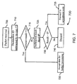
- FIG. 7 is a flow chart illustrating an exemplary process for data forwarding in a communication system
- FIG. 8 is a flow chart illustrating another exemplary process for data forwarding in a communication system
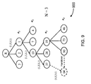
- FIG. 9 is a schematic diagram illustrates a handover of a network node
- FIG. 10a is a schematic diagram illustrates a mesh topology network
- FIG. 10b is a schematic diagram illustrates logical trees formed in the mesh network of FIG. 10a ;
- FIG. 11 is a schematic diagram illustrates inter logical tree data transmitting
- FIG. 12 is an exemplary flow chart of a data transmitting consistent with embodiments of the invention.
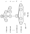
- a logical tree-based topology may be formed a network including a plurality of nodes by designating one of the network nodes as a root node, and one or more other nodes as child nodes among the plurality of nodes of the network.
- Fig. 2 is a schematic example of a network 200 configured to have such a logical tree-based topology consistent with embodiments of the invention.
- the tree based topology configured with a maximum number of k child levels.
- the communication system could be any network topology, for example, a tree-based network or a mesh network.
- Each of the child nodes in a k th child level of network 200 is assigned an identification a k for each parent node to identify this child node, where identification a k could be any number.
- identification a k could be an integer greater than or equal to 0, and less than or equal to N, N is a determined number.
- N may be pre-defined to any arbitrary number or to a maximum number of child nodes connected to each of the plurality of nodes of the tree topology. In some implementation, the determined number N could maintain by the system dynamically.
- identification a k may be assigned by a random sequence or sequentially. In one example, identification a k of each child node may be assigned according to a sequence in which it becomes associated with its parent node.
- child nodes of node S are connected to form the k th child level of the tree topology and N child nodes are connected to Node S.
- the identification a k of each of the child nodes of node S could be assigned a number selected within 1 to N.
- One of the implementation could be to assign N as identification a k of node T, N-1 as identification a k of node U, ..., 2 as identification a k of node Y and 1 as identification a k of node Z.
- the identification a k each of the child nodes of node S could instead be assigned a number selects within 0 to N-1, for example, identification a k of node T is assigned as 0, identification a k of node U is assigned as 1, ..., identification a k of node Y is assigned as N-2 and identification a k of node Z is assigned as N-1.
- the identification a 1 of 1 st child level is assigned from 1 to N-1, and the determined number N is 2 i , where i is an integer equal to or greater than 0.
- the root node or at least one of some other nodes with control capability or a child node may store information to generate the node IDs, and manage data forwarding or network configuration.
- Other information or parameters could also be provided, and the kind of information to be stored optionally depends on the implementation.
- Embodiments of the present invention may be practiced in any network communication system.
- multi-hop relay networks are described as exemplary communication systems to demonstrate data transmitting algorithms for generating a node ID in a communication network environment in which there is a determined number N of nodes, wherein the node IDs are utilized to transmit data.
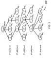
- Fig. 3 illustrates an exemplary multi-hop relay network 300 that includes a multi-hop relay base station (MR-BS) and multiple relay stations (RSs).
- MR-BS multi-hop relay base station
- RSs relay stations
- Mobile stations may be associated with either MR-BS or RS.
- Network 300 is configured to have a logical tree topology including a MR-BS root node 302 having five child levels.
- the identification a k of each of the nodes of other child levels is a sequentially assigned integer from 0 to 3 in this exemplary example.
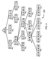
- Fig. 4 illustrates network 300 in which node IDs are represented in binary notation.
- the node IDs of the first child level nodes are assigned by an integer selected within 1 to 2 i -1 by setting different values of the lowest i bits of each node ID.
- a control node MR-BS for example, left shifts i bits of the parent node ID of each child and sets different values of the lowest i bits by selecting an integer within 0 to 2 i -1. This process could be used to generate the node IDs for newly arriving nodes or for connecting the child nodes RS.
- control node MR-BS left shifts 2 bits of its own ID, as a parent node, resulting in 00 01 00 00, and sets the lowest 2 bits as 10 since node RS I is the third node that attaches to RS D , resulting in 00 01 00 10.
- node MR-BS assigns 00 01 00 11 to node RS J after assigning the ID to node RS I .
- the node IDs of the first child level nodes could also be assigned by an integer by setting different values of the highest i bits of each node ID. While for the nodes of other child levels, a control node, MR-BS for example, right shifts i bits of the parent node ID of each child and sets different values of the highest i bits by selecting an integer within 0 to 2 i -1.
- each child node may assign an identification a k
- a node ID of each of the nodes of the first child level may assign its own identification a 1
- the node ID of each of nodes of other child levels is assigned by performing an operation of left shifting i bits of the parent node ID of each of the child nodes and setting the lowest i bits to the identification a k of each of the child nodes.
- the MR-BS To assign an ID to RS I , the MR-BS perform a left shift of 2 bits of the ID of the parent node RS D and adds binary "10" (decimal 2, its identification a 3 ) resulting in decimal 18. Similarly, node ID 19 of RS J is generated by left shifting 2 bits of the parent node ID and adding 3, it's a 3 identification.
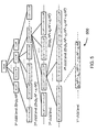
- Fig. 5 illustrates an exemplary embodiment of an N-carry operation as a polynomial.
- the node ID of each child node of the first child level is generated by a polynomial (a 1 ⁇ N 0 )
- the node ID of each child node of the second child level is generated by a polynomial (a 2 ⁇ N 1 + a 1 ⁇ N 0 )
- the node ID of each child node of the third child level is generated by a polynomial (a 3 ⁇ N 2 + a 2 ⁇ N 1 + a 1 ⁇ N 0 )
- the node ID of each child node of the fourth child level is generated by a polynomial (a 4 ⁇ N 3 + a 3 ⁇ N 2 + a 2 ⁇ N 1 + a 1 ⁇ N 0 ).
- the N-carry operation of child nodes of the k th child level is performed by adding a k ⁇ N k-1 to the parent node ID.
- data could be transmitted by utilizing the node IDs of child nodes.
- a destination node ID of the data is checked against the node ID of each child node, and each child node accepts the data for further processing if the destination node ID is the node ID of each such child node; and decides to forward the data to subordinate child nodes or to discard the data depending on whether the destination node ID is not the node ID of the child node.
- Fig. 7 is a flowchart illustrating an exemplary example of data transmission in a communication system.
- the receiving node subtracts its own node ID from the destination node ID (step 710). If the subtraction result equals 0 (step 715, yes), the node accepts (receives) the data packet for further processing (step 720). If the subtraction result is not 0 (step 715, no), the subtraction result is subjected to a modulo N k operation (step 725). If the result of the modulo operation equals 0 (step 730, yes), the node forwards the data to its subordinate child nodes (step 735). Otherwise (step 730, no), the data is discarded (step 740).
- tree topology 600 is used to explain a data forwarding example for a data packet destined for node X4 having ID 672.
- ID 672 is subjected to subtraction by 2. Because the subtraction result is not equal 0, node X1 determines that is not the destination of the packet and subjects the subtraction result to the modulo N k operation. After the calculation, the modulo result is 0 so that node X1 forwards the packet to subordinate nodes. The same process is executed in nodes X2 and X3.
- node X4 receives the forwarded data packet, it subtracts its ID from the node ID of the packet. The subtraction result is 0, so node X4 receives the packet for further processing.
- the modulo result is not 0 so these nodes discard the data packet.
- each RS may determine its level and perform forwarding of data packets efficiently.
- each RS may readily determine its parent ID by right shifting i bits of its own ID.
- the ID of RS M is 01 00 10 10
- RS M knows the ID of its parent node RS I is 00 01 00 10 by right shifting 2 bits of its ID.
- the child node needs to determine if it should accept, forward, or discard the frame, such as in accordance with the process shown in Fig. 7 .
- a node receiving a data packet checks if the destination node ID of the packet is equal to its own ID (step 810) and accepts the frame if these two IDs are the same (step 810, yes). If the two IDs are not the same, the node performs an i -bit right shift of the destination node ID (step 820) and checks the result against its own ID (step 830).
- the node discards the frame if all checks fail (step 840, yes).
- the step 820 performs left shift instead of right shift and the other steps remain the same procedure.
- the network topology could be changed accordingly, and node IDs may need to be updated as a consequence of the possible change of allowable connected child nodes at any child level in the logical tree topology.
- the network identifies the maximum number of child nodes, broadcasts or forwards the maximum number, and updates the node ID of each of the child nodes.
- a root node or another designated node with network control capability may process the identifying and broadcasting/forwarding, and each of the child nodes may update its own ID based on the broadcasted or forwarded information to generate the node ID, for example by identifying a set ⁇ a 1 , a 2 , ..., a k ⁇ or based on decoding its own old node ID, for example, by bit shifting the old node ID.
- the information could be stored in the child node or forwarded by at least one node with network control capability during a broadcasting or forwarding process.
- a communication node 220 of the network system the invention disclosed may include one or more of the following components: at least one central processing unit (CPU) 221 configured to execute computer program instructions to perform various processes and methods, random access memory (RAM) 222 and read only memory (ROM) 223 configured to access and store information and computer program instructions, memory 224 or one or more databases 225 to store information and data, one or more antenna 226, one or more I/O device 227 and one or more Interface 228, etc.
- CPU central processing unit
- RAM random access memory
- ROM read only memory
- memory 224 or one or more databases 225 to store information and data
- antenna 226, one or more I/O device 227 and one or more Interface 228, etc are well-known in the art and will not be discussed further.
- Fig. 9 illustrates an exemplary network 900 which illustrates a node handover from a parent node to another node.
- the root node or another node has control capability to forward to the handover node its new information for generating a node ID, for example ⁇ a 1 ', a 2 ', ..., a k ' ⁇ .
- the handover node may generate the new node ID.
- the node with ID 90 decides to handover from parent node 19 to another parent node 37.
- the root node forwards new information, e.g., ⁇ 1, 3, 3, 1 ⁇ , to the handover node.
- the handover node may update its new node ID during or after the handover process.
- Fig. 10a is an example of a mesh topology network 1000 mapped to logical trees consistent with embodiments of the invention.
- Fig. 10b illustrates three logical trees formed in network 1000 with connecting nodes.
- the three logical trees are logical tree 1 (1010) having node 1 as a root node, logical tree 2 (1020) having node 8 as a root node, and logical tree 3 (1030) having root node 9 as a root node.
- the gateway to an external network is taken as the root node in a logical tree network.
- the packet When forwarding a packet in the logical tree network, the packet may include a destination address including at least a logical tree prefix field 1001 and a destination node ID field 1002 as illustrated in Fig. 10a .
- a node that receives a packet with a destination address assigns a logical tree prefix to forward the data. For example, in order for node 4 to transmit a packet to node 9 using logical tree 1 (1010), node 4 assigns 1 to the logical tree prefix field, and allocates the ID of node 9 of logical tree 1 to the destination node ID field of the destination address.
- each node may transform a destination address by modifying the prefix and node ID.
- Fig. 11 shows an exemplary schematic diagram 1100 illustrating transmission of data between logical trees.
- node 8 In order for node 8 to send a packet to node 9, node 8 inserts the logical tree prefix field 1 and inserts the node ID of node 9 in logical tree 1 as the destination node ID field, and forwards the packet via logical tree 1.
- node 7 decides to forward the packet via logical tree 2, by utilizing a conventional algorithm to make that decision.
- Node 7 changes the logical prefix field to 2, and transforms the node ID of node 9 in logical tree 1 (represented by the notation 9 1 ) into the node ID of node 9 in logical tree 2 (9 2 ).
- the packet is forwarded to node 9 using the node ID 9 2 and the data transmitting algorithm of logical tree 2.
- the system may assign a different logical tree prefix value and transform the destination node ID in original logical tree to the node ID in the assigned logical tree, to transmit data utilizing one or more logical trees.
- Fig. 12 illustrates an example of a data transmitting flow chart.
- a network node receives a packet and extracts the destination address of the packet (step 1210), it identifies the logical tree prefix (step 1220) and identifies the destination node ID of the logical tree (step 1230). After identifying the destination node ID, the receiving node decides whether to forward the packet to another logical tree or not (step 1240).
- the receiving node may uses any conventional or any of previous described data transmitting methods base on assigning node ID (data transmitting algorithm) of the identified logical tree (step 1250), if not forwarding the packet by another logical tree (step 1240, No).
- the node decides to forward the packet by another logical tree (step 1240, Yes)
- the node indicates a new logical tree in the logical tree prefix field and transforms the destination node ID into the node ID of the new logical tree (step 1270) after the new logical tree is assigned by some algorithm (step 1260).
- the packet is forwarded via the new path by utilizing the data transmitting algorithm of the new logical tree (step 1280).
Abstract

Description
- The present disclosure relates generally to network systems and, specially relates to method and system for network node data transmitting.
- In communication systems a network node (or so called host) can allocate its ID or address statically or dynamically. In a static configuration, users need to acquire an available address in advance and manually configure the address. In contrast, in a flexible multi-hop environment, such as the type described in IEEE 802.16j, it is not reasonable for operators or users to perform manual configuration. Another choice, dynamic configuration, allows a node to configure its ID or acquire an ID from a centralized server dynamically. In a typical dynamic configuration scheme, all node IDs are assigned randomly, and additional routing algorithms or routing tables are required in order for nodes to exchange or maintain additional routing information and to decide routing paths.
-
Fig. 1 illustrates an exemplary multi-hop relay (MR)network 100. Innetwork 100, a multi-hop relay base station BS (MR-BS) 102 acts as a root node, and relay stations (RSs) and mobile stations (MSs) act as intermediate nodes or leaf nodes. A network setup process assigns each network node an identification (or address) and constructs routing groups between nodes. For example,RS3 104 is assigned an address and is responsible for forwarding packets from MR-BS destined toRS4 106, and RS 1 108 will drop the packets it receives from MR-BS that are destined to RS3. Such routing information may be maintained in a routing table of each RS so that when an intermediate node leaves or enters the network, that newest routing information can be updated. - Two examples show utilization of routing tables.
USP 6,192,051 discloses a multi-level tree data structure in a centralized routing table and in distributed forwarding tables for forwarding network packets. Each level of each structure is associated with a different field of a network address appearing in received packets.USP 6,934,252 discloses binary network address lookups using parent node information stored in routing table entries. Variable length prefixes are stored in a network address forwarding table. Each prefix corresponds to an entry in the forwarding table. Each entry in the forwarding table includes path information regarding parent nodes of each entry in the binary tree. - Node identification may be performed without maintaining a routing table.
USP 6,618,755 discloses a software facility for automatically identifying subnets in a network by a range of addresses within the network represented by nodes in the network. The addresses each include an ordered series of a fixed number of bits. - A prime factorization method to represent nodes of a network and groups between nodes is described in
US2006/0198320 , as well as in IEEE C802.16j-06/171. In the forwarding process of this method, a receiving node needs to factorize the ID number of the packet received to determine where to forward the packet. Another method is described in IEEE C802.16j-07/048r6, which relates to a contiguous integer block routing method, in which a network node identifies the integer block of a received address to determine where to forward the packet or if it should drop the packet. - In one exemplary embodiment consistent with the present disclosure is a method for transmitting data in a network. The method comprises forming a logical tree topology by connecting a root node and one or more child nodes among a plurality of nodes in the network; generating a node ID for each of the child nodes by a N-carry operation of a determined number N, and transmitting data by utilizing the generated node ID of the child nodes.
- In another exemplary embodiment consistent with the present disclosure is a communication system. The system comprises a plurality of communication nodes interconnected to form a network, and a root node and one or more child nodes are connected among the plurality of communication nodes to form a logical tree topology; each of the child nodes having assigned thereto a node ID generated by a N-carry operation of a determined number N; and wherein data is transmitted by utilizing the assigned node IDs of the child nodes.
- Yet in another exemplary embodiment consistent with the present disclosure is a communication node in a transmission-receiving group of a network, the network including a plurality of network nodes and the transmission-receiving group including at least one transmission node and at least one receiving node. The communication node comprising: at least one memory to store data and instructions; and at least one processor configured to access the memory, and when executing the instructions, configured to: transmitting a communication data by utilizing a node ID, the node ID is being assigned by a N-carry operation of a determined number N.
- The invention will be further described by way of example with reference to the accompanying drawings, in which:-
-
FIG. 1 is a block diagram of a multi-hop relay network; -
FIG. 2a illustrates a schematic exemplary example of a logical tree topology; -
FIG. 2b illustrates an exemplary example of block diagram of a communication node; -
FIG. 3 illustrates an exemplary network node ID assignment of a communication system consistent with certain disclosed embodiments; -
FIG. 4 illustrates an ID assignment operation by expanding the node IDs assigned inFig. 3 with binary form; -
FIG. 5 illustrates another exemplary network node ID assignment of a communication system utilizing an N-carry operation by a polynomial consistent with certain disclosed embodiments; -
FIG. 6 further illustrates the exemplary N-carry operation node ID assignment ofFig. 5 consistent with certain disclosed embodiments; -
FIG. 7 is a flow chart illustrating an exemplary process for data forwarding in a communication system; -
FIG. 8 is a flow chart illustrating another exemplary process for data forwarding in a communication system; -
FIG. 9 is a schematic diagram illustrates a handover of a network node; -
FIG. 10a is a schematic diagram illustrates a mesh topology network; -
FIG. 10b is a schematic diagram illustrates logical trees formed in the mesh network ofFIG. 10a ; -
FIG. 11 is a schematic diagram illustrates inter logical tree data transmitting; and -
FIG. 12 is an exemplary flow chart of a data transmitting consistent with embodiments of the invention. - In a communication system environment, data could be transmitted among a transmitting-receiving group of plurality of communication nodes through a transmitting-receiving path from a first level transmission node to its first level receiving node or subsequent levels of receiving nodes. As an exemplary example, a logical tree-based topology may be formed a network including a plurality of nodes by designating one of the network nodes as a root node, and one or more other nodes as child nodes among the plurality of nodes of the network.
Fig. 2 is a schematic example of anetwork 200 configured to have such a logical tree-based topology consistent with embodiments of the invention. The tree based topology configured with a maximum number of k child levels. More broadly, the communication system could be any network topology, for example, a tree-based network or a mesh network. - Each of the child nodes in a kth child level of
network 200 is assigned an identification ak for each parent node to identify this child node, where identification ak could be any number. During an implementation stage, identification ak could be an integer greater than or equal to 0, and less than or equal to N, N is a determined number. N may be pre-defined to any arbitrary number or to a maximum number of child nodes connected to each of the plurality of nodes of the tree topology. In some implementation, the determined number N could maintain by the system dynamically. Furthermore, identification ak may be assigned by a random sequence or sequentially. In one example, identification ak of each child node may be assigned according to a sequence in which it becomes associated with its parent node. - As illustrated in
Fig. 2a , child nodes of node S are connected to form the kth child level of the tree topology and N child nodes are connected to Node S. In one exemplary embodiment consistent with the invention, the identification ak of each of the child nodes of node S could be assigned a number selected within 1 to N. One of the implementation could be to assign N as identification ak of node T, N-1 as identification ak of node U, ..., 2 as identification ak of node Y and 1 as identification ak of node Z. - In another exemplary embodiment consistent with the invention, the identification ak each of the child nodes of node S could instead be assigned a number selects within 0 to N-1, for example, identification ak of node T is assigned as 0, identification ak of node U is assigned as 1, ..., identification ak of node Y is assigned as N-2 and identification ak of node Z is assigned as N-1. In this example, the identification a1 of 1st child level is assigned from 1 to N-1, and the determined number N is 2 i , where i is an integer equal to or greater than 0.
- The root node or at least one of some other nodes with control capability or a child node may store information to generate the node IDs, and manage data forwarding or network configuration. For example, such information may include : the determined number N, a maximum child node number of a parent node in a logical tree topology, an integer i in the implementation of N=2', identification ak of the child node, the child level k of the child node, a set of identification {a1,a2, ..., ak-1} along a parent-child path from the first child level of the root node to the child node, and a maximum child level H of the logical tree. Other information or parameters could also be provided, and the kind of information to be stored optionally depends on the implementation.
- Embodiments of the present invention may be practiced in any network communication system. For exemplary purposes, in the following paragraphs, multi-hop relay networks are described as exemplary communication systems to demonstrate data transmitting algorithms for generating a node ID in a communication network environment in which there is a determined number N of nodes, wherein the node IDs are utilized to transmit data.
- The node ID of each child node may be generated by a 2's carry operation, as explained in the following paragraphs.
Fig. 3 illustrates an exemplarymulti-hop relay network 300 that includes a multi-hop relay base station (MR-BS) and multiple relay stations (RSs). Mobile stations (MSs, not shown in figure) may be associated with either MR-BS or RS. -
Network 300 is configured to have a logical tree topology including a MR-BS root node 302 having five child levels. The first child level contains child nodes RSA(a1=1, ID=1), RSB (a1=2, ID=2) and RSc(a1=3, ID=3). The second child level contains nodes: RSD(a2=0, ID=4) which is a child node of RSA, and RSE (a2=0, ID=12) and RSF(a2=1, ID=13) which are child nodes of node RSc. The third child level contains the following child nodes of RSD: RSG(a3=0, ID=16), RSH(a3=1, ID=17), RSI(a3=2, ID=18), and RSJ(a3=3, ID=19). The fourth child level contains three child nodes of ode RS1: RSK(a4=0, ID=72), RSL(a4=1, ID=73), and RSM(a4=2, ID=74). The fifth child level contains four child nodes of node RSK: RSN(a5=0, ID=288), RSO(a5=1, ID=289), RSP(a5=2, ID=290), and RSQ(a5=3, ID=291). - In the configuration of
network 300, i=2 so that the determined number N=2 i of child nodes is 2 2 =4, the maximum child level H is 5, and the identification ak of each of the nodes of the first child level (k=1) is a sequentially assigned integer from 1 to 3. Relative to each parent node, the identification ak of each of the nodes of other child levels is a sequentially assigned integer from 0 to 3 in this exemplary example. -
Fig. 4 illustratesnetwork 300 in which node IDs are represented in binary notation. By converting the node ID of each of the child nodes of the logical tree topology ofnetwork 300 into binary notation, it becomes possible to perform a 4-carry operation to generate the node IDs ofnetwork 300. Moreover, the computations of node ID assignments may be accomplished by bit operations. - With reference to
Fig. 4 and as an exemplary implementation consistent with embodiments of the invention, the node IDs of the first child level nodes are assigned by an integer selected within 1 to 2 i -1 by setting different values of the lowest i bits of each node ID. For the nodes of other child levels, a control node, MR-BS for example, left shifts i bits of the parent node ID of each child and sets different values of the lowest i bits by selecting an integer within 0 to 2 i -1. This process could be used to generate the node IDs for newly arriving nodes or for connecting the child nodes RS. For example, it is assumed that nodes RSI and RSj newly arrive one after another to associate with node RSD (ID = 00 00 01 00) as their parent node, after arrival of nodes RSG and RSH inFig. 4 . To assign an ID to RSI, control node MR-BS left shifts 2 bits of its own ID, as a parent node, resulting in 00 01 00 00, and sets the lowest 2 bits as 10 since node RSI is the third node that attaches to RSD, resulting in 00 01 00 10. Similarly, node MR-BS assigns 00 01 00 11 to node RSJ after assigning the ID to node RSI. Using a similar manner (not shown in the figure), the node IDs of the first child level nodes could also be assigned by an integer by setting different values of the highest i bits of each node ID. While for the nodes of other child levels, a control node, MR-BS for example, right shifts i bits of the parent node ID of each child and sets different values of the highest i bits by selecting an integer within 0 to 2 i -1. - Referring again to
Fig. 3 , in another exemplary embodiment, each child node may assign an identification ak, and a node ID of each of the nodes of the first child level may assign its own identification a1. The node ID of each of nodes of other child levels is assigned by performing an operation of left shifting i bits of the parent node ID of each of the child nodes and setting the lowest i bits to the identification ak of each of the child nodes. For example, inFig. 3 RSI and RSJ are associated with a common parent node RSD (ID = 4) (00 00 01 00). To assign an ID to RSI, the MR-BS perform a left shift of 2 bits of the ID of the parent node RSD and adds binary "10" (decimal 2, its identification a3) resulting indecimal 18. Similarly,node ID 19 of RSJ is generated by left shifting 2 bits of the parent node ID and adding 3, it's a3 identification. - The operation of assigning identifications of the child nodes could be an N-carry operation.
Fig. 5 illustrates an exemplary embodiment of an N-carry operation as a polynomial. With reference toFig. 5 , each child node of a kth child level of a tree topology of network nodes in acommunication system 500 has a node ID = (ak·Nk-1+ ak-1·Nk-2+ ...+ a2·N1 + a1·N0). The node ID of each child node of the first child level is generated by a polynomial (a1·N0), the node ID of each child node of the second child level is generated by a polynomial (a2·N1 + a1·N0) the node ID of each child node of the third child level is generated by a polynomial (a3·N 2+ a2·N1 + a1·N0), and the node ID of each child node of the fourth child level is generated by a polynomial (a4·N3+ a3·N2+ a2·N1 + a1·N0). The previously described 2's carry operation illustrated byFigs. 3 and4 could also be expressed by the same polynomial form with N=2 i . -
Figure 6 shows an exemplary embodiment of node ID assignment using an N-carry operation in a communication system having alogical tree topology 600 with N=5. The node ID of node X1 in the first child level is assigned to be 2, generated by (2 × 5 0 = 2). The node ID of node X2 ofchild level 1 is 22, generated by (2 × 5 0 + 4 × 5 1 =22). Following the same polynomial computation rule, nodes X3 and X4 are assigned 47 and 672, respectively, generated by (2 × 5 0 + 4 × 5 1 + 1 × 5 2 =47) and (2 × 5 0 + 4 × 5 1 + 1 × 5 2 + 5 × 5 3 =672) respectively. The N-carry operation of child nodes of the kth child level is performed by adding ak·Nk-1 to the parent node ID. - By use of the illustrated node ID assignment embodiments, during a data routing process, data could be transmitted by utilizing the node IDs of child nodes. When forwarding data, a destination node ID of the data is checked against the node ID of each child node, and each child node accepts the data for further processing if the destination node ID is the node ID of each such child node; and decides to forward the data to subordinate child nodes or to discard the data depending on whether the destination node ID is not the node ID of the child node.
-
Fig. 7 is a flowchart illustrating an exemplary example of data transmission in a communication system. Each time a node receives a data packet having a destination node ID (step 705), the receiving node subtracts its own node ID from the destination node ID (step 710). If the subtraction result equals 0 (step 715, yes), the node accepts (receives) the data packet for further processing (step 720). If the subtraction result is not 0 (step 715, no), the subtraction result is subjected to a modulo Nk operation (step 725). If the result of the modulo operation equals 0 (step 730, yes), the node forwards the data to its subordinate child nodes (step 735). Otherwise (step 730, no), the data is discarded (step 740). - Referring again to
Fig. 6 ,tree topology 600 is used to explain a data forwarding example for a data packet destined for nodeX4 having ID 672. When node X1 receives the packet,ID 672 is subjected to subtraction by 2. Because the subtraction result is not equal 0, node X1 determines that is not the destination of the packet and subjects the subtraction result to the modulo Nk operation. After the calculation, the modulo result is 0 so that node X1 forwards the packet to subordinate nodes. The same process is executed in nodes X2 and X3. When node X4 receives the forwarded data packet, it subtracts its ID from the node ID of the packet. The subtraction result is 0, so node X4 receives the packet for further processing. When the other child nodes receive the forwarded data packet, after the modulo calculation, the modulo result is not 0 so these nodes discard the data packet. - With the routing-embedded ID assignment illustrated with
Fig. 4 , each RS may determine its level and perform forwarding of data packets efficiently. For upstream frames, each RS may readily determine its parent ID by right shifting i bits of its own ID. For example, the ID of RSM is 01 00 10 10, so that RSM knows the ID of its parent node RSI is 00 01 00 10 by right shifting 2 bits of its ID. For downstream frames received from its parent node, the child node needs to determine if it should accept, forward, or discard the frame, such as in accordance with the process shown inFig. 7 . -
Figure 8 illustrates a flowchart for a data transmitting process consistent with the exemplary embodiment of the invention illustrated inFig. 4 , the node IDs of child nodes are assigned by left shifts i bits of the parent node ID of each child and setting different values of the lowest i bits of each node ID, wherein N=2'. A node receiving a data packet checks if the destination node ID of the packet is equal to its own ID (step 810) and accepts the frame if these two IDs are the same (step 810, yes). If the two IDs are not the same, the node performs an i-bit right shift of the destination node ID (step 820) and checks the result against its own ID (step 830). If the shifted destination node ID is the same as the node's own ID, the node forwards the frame to its subordinate child node (step 830, yes). Otherwise, it continues to right shift and check (step 820, 830) j times (step 840, 850), where j =(H-k), where H is the maximum number of child levels and k is the child level of the data transmitting node. The node discards the frame if all checks fail (step 840, yes). Similarly, when the node IDs of the child nodes are assigned by right shifts i bits of the parent node ID of each child and setting different values of the highest i bits of each node ID, during the data transmitting process, thestep 820 performs left shift instead of right shift and the other steps remain the same procedure. - When nodes enter and leave a communication system, the network topology could be changed accordingly, and node IDs may need to be updated as a consequence of the possible change of allowable connected child nodes at any child level in the logical tree topology. For example in some implementation the network identifies the maximum number of child nodes, broadcasts or forwards the maximum number, and updates the node ID of each of the child nodes.
- A root node or another designated node with network control capability may process the identifying and broadcasting/forwarding, and each of the child nodes may update its own ID based on the broadcasted or forwarded information to generate the node ID, for example by identifying a set {a1, a2, ..., ak} or based on decoding its own old node ID, for example, by bit shifting the old node ID. The information could be stored in the child node or forwarded by at least one node with network control capability during a broadcasting or forwarding process.
- As shown in
Fig. 2b , acommunication node 220 of the network system the invention disclosed may include one or more of the following components: at least one central processing unit (CPU) 221 configured to execute computer program instructions to perform various processes and methods, random access memory (RAM) 222 and read only memory (ROM) 223 configured to access and store information and computer program instructions,memory 224 or one ormore databases 225 to store information and data, one ormore antenna 226, one or more I/O device 227 and one ormore Interface 228, etc. Each of these components is well-known in the art and will not be discussed further. -
Fig. 9 illustrates anexemplary network 900 which illustrates a node handover from a parent node to another node. The root node or another node has control capability to forward to the handover node its new information for generating a node ID, for example {a1', a2', ..., ak'}. After receiving the information, the handover node may generate the new node ID. InFig. 9 , the node withID 90 decides to handover fromparent node 19 to anotherparent node 37. The root node forwards new information, e.g., {1, 3, 3, 1}, to the handover node. As a result, the handover node may update its new node ID during or after the handover process. -
Fig. 10a is an example of amesh topology network 1000 mapped to logical trees consistent with embodiments of the invention.Fig. 10b illustrates three logical trees formed innetwork 1000 with connecting nodes. The three logical trees are logical tree 1 (1010) havingnode 1 as a root node, logical tree 2 (1020) havingnode 8 as a root node, and logical tree 3 (1030) havingroot node 9 as a root node. In general, the gateway to an external network is taken as the root node in a logical tree network. - When forwarding a packet in the logical tree network, the packet may include a destination address including at least a logical
tree prefix field 1001 and a destinationnode ID field 1002 as illustrated inFig. 10a . A node that receives a packet with a destination address assigns a logical tree prefix to forward the data. For example, in order fornode 4 to transmit a packet tonode 9 using logical tree 1 (1010),node 4 assigns 1 to the logical tree prefix field, and allocates the ID ofnode 9 oflogical tree 1 to the destination node ID field of the destination address. - For forwarding packets between logical trees, due to the different prefixes and node IDs in different logical trees, each node may transform a destination address by modifying the prefix and node ID.
Fig. 11 shows an exemplary schematic diagram 1100 illustrating transmission of data between logical trees. In order fornode 8 to send a packet tonode 9,node 8 inserts the logicaltree prefix field 1 and inserts the node ID ofnode 9 inlogical tree 1 as the destination node ID field, and forwards the packet vialogical tree 1. When receiving the packet,node 7 decides to forward the packet vialogical tree 2, by utilizing a conventional algorithm to make that decision.Node 7 changes the logical prefix field to 2, and transforms the node ID ofnode 9 in logical tree 1 (represented by the notation 91) into the node ID ofnode 9 in logical tree 2 (92). The packet is forwarded tonode 9 using thenode ID 92 and the data transmitting algorithm oflogical tree 2. In this manner, the system may assign a different logical tree prefix value and transform the destination node ID in original logical tree to the node ID in the assigned logical tree, to transmit data utilizing one or more logical trees. -
Fig. 12 illustrates an example of a data transmitting flow chart. When a network node receives a packet and extracts the destination address of the packet (step 1210), it identifies the logical tree prefix (step 1220) and identifies the destination node ID of the logical tree (step 1230). After identifying the destination node ID, the receiving node decides whether to forward the packet to another logical tree or not (step 1240). The receiving node may uses any conventional or any of previous described data transmitting methods base on assigning node ID (data transmitting algorithm) of the identified logical tree (step 1250), if not forwarding the packet by another logical tree (step 1240, No). If the node decides to forward the packet by another logical tree (step 1240, Yes), the node indicates a new logical tree in the logical tree prefix field and transforms the destination node ID into the node ID of the new logical tree (step 1270) after the new logical tree is assigned by some algorithm (step 1260). The packet is forwarded via the new path by utilizing the data transmitting algorithm of the new logical tree (step 1280). - It will be apparent to those skilled in the art that various modifications and variations may be made in the system and method for reducing signal interference in communication networks. It is intended that the standard and examples be considered as exemplary only, with a true scope of the disclosed embodiments being indicated by the following claims and their equivalents.
Claims (90)
- A method for transmitting data in a network environment having a plurality of communication nodes, the method comprising:transmitting a data from at least one transmission node to at least one receiving node of a transmission-receiving group among the plurality of communication nodes by utilizing a node ID, the node ID is being assigned by a N-carry operation of a determined number N.
- The method as in claim 1, further including assigning a root node and one or more child nodes among the plurality of communication nodes of the transmission-receiving group to form a logical tree topology, wherein each of the child nodes is a parent node of 0, one or more other ones of child nodes.
- The method as in claim 2, wherein the determined number N is the maximum number of child nodes connecting to each of the nodes of the logical tree topology.
- The method as in claim 2, further including assigning, for each parent node, an identification ak for each of the child nodes, in a kth child level of the logical three topology, relative to parent nodes to identify each of said child nodes.
- The method as in claim 4, wherein the N-carry operation is being performed by a polynomial ak·Nk-1 + ak-1·Nk-2 + ... + a2·N1 + a1·N0, wherein {a1, a2, ..., ak-1, ak} is a set of identifications of child nodes along a transmission-receiving path from a first child level of the root node to said child node for which the node ID is being assigned.
- The method as in claim 1, further including assigning, for each transmission node, an identification ak for each of the receiving nodes, in a kth receiving level of the transmission-receiving group, relative to the transmission nodes to identify each of said receiving nodes.
- The method as in claim 6, wherein the N-carry operation is being performed by a polynomial ak·Nk-1 + ak-1·Nk-2 + ... + a2·N1 + a1·N0, wherein {a1, a2, ..., ak-1, ak} is a set of identifications of receiving nodes along a transmission-receiving path from a first receiving level of a first level transmission node to said receiving node for which the node ID is being assigned.
- The method as in claim 1, 2, 4 or 5 wherein the determined number N is equal to 2 i , i being an integer equal to or greater than zero.
- The method as in claim 8, wherein the determined number N is the maximum number of child nodes connecting to each of nodes of the logical tree topology.
- The method as in claim 8, wherein the N-carry operation of child nodes in each child level other than the first child level is being performed by left shifting i bits of a parent node ID and setting different values of lowest i bits of the shifted node ID for the respective child nodes of the child level, and assigning the node ID of each of nodes of the first child level nodes by setting different values of lowest i bits of the node ID of the respective first child level nodes.
- The method as in claim 8, wherein the N-carry operation of child nodes in each child level other than the first child level is being performed by left shifting i bits of the parent node ID and setting lowest i bits of the shifted node ID as an integer selected within 0 to 2 i -1, and assigning the node ID of each of nodes of the first child level nodes as an integer selected within 1 to 2 i -1.
- The method as in claim 11, wherein the node ID of each of said child nodes is being assigned according to a sequence in which the child node being associated with its parent node.
- The method as in claim 8, wherein the N-carry operation of child nodes in each child level other than the first child level is being performed by right shifting i bits of a parent node ID and setting different values of highest i bits of the shifted node ID for the respective child nodes of the child level, and assigning the node ID of each of nodes of the first child level nodes by setting different values of the highest i bits of the node ID of the respective first child level nodes.
- The method as in claim 8, wherein the N-carry operation of child nodes in each child level other than the first child level is being performed by right shifting i bits of the parent node ID and setting highest i bits of the shifted node ID as an integer selected within 0 to 2 i -1, and assigning the node ID of each of nodes of the first child level nodes by setting highest i bits an integer selected within 1 to 2 i -1.
- The method as in claim 14, wherein the node ID of each of said child nodes is being assigned according to a sequence in which the child node being associated with its parent node.
- The method as in claim 4 or 5, further including assigning to the identification ak a number selected within 1 to N.
- The method as in claim 8, further including assigning to the identification ak of each of nodes of a first child level an integer selected within 1 to N-1, and assigning to the identification ak of each of nodes of other child levels an integer selected within 0 to N-1.
- The method as in claim 17, further including assigning to said identification ak of each of said child nodes according to a sequence in which the child node being associated with its parent node.
- The method as in claim 17, wherein the N-carry operation of child nodes in each child level other than the first child level is being performed by left shifting i bits of the parent node ID of each of said child nodes and setting lowest i bits of the shifted node ID to the identification ak of each of said child nodes, and assigning the node ID of each of the nodes of the first child level its own identification a1.
- The method as in claim 17, wherein the N-carry operation of child nodes in each child level other than the first child level is being performed by right shifting i bits of the parent node ID of each of said child nodes and setting highest i bits of the shifted node ID to the identification ak of each of said child nodes, and assigning the node ID of each of the nodes of the first child level by setting highest i bits of the node ID of the respective first child level nodes its own identification a1.
- The method as in claim 1, 5, 10 or 13, wherein the transmitting further includes each node transmitting data checking a destination ID of the data with its own node ID, accepting the data for further processing if the destination ID is its own node ID.
- The method as in claim 21, wherein the checking is performed by subtracting the destination ID by its own node ID.
- The method as in claim 22, wherein the checking by each node transmitting data, if the destination ID is not its own node ID, further includes:forwarding the data to subordinate receiving nodes of the kth receiving level if the subtraction result is not zero and the result of subtraction result modulo by Nk is zero.
- The method as in claim 23, wherein the checking by each node transmitting data, if the destination ID is not its own node ID, further includes:discarding the data if the subtraction result is not zero and the result of subjecting the subtraction result to modulo by Nk is not zero.
- The method as in claim 21, wherein the checking by each node transmitting data, if the destination ID is not its own node ID, further includes:right shifting the destination ID i bits;checking the shifted ID, forwarding the data to subordinate child nodes if the shifted ID is its own node ID; andrepeating j times of the right shifting and checking of the shifted ID, j being equal to a difference between a maximum number of child levels and a child level of the data transmitting node.
- The method as in claim 21, wherein the checking by each node transmitting data, if the destination ID is not its own node ID, further includes:left shifting the destination ID i bits;checking the shifted ID, forwarding the data to subordinate child nodes if the shifted ID is its own node ID; andrepeating j times of the left shifting and checking of the shifted ID, j being equal to a difference between a maximum number of child levels and a child level of the data transmitting node.
- The method as in claim 25 or 26, wherein the checking by each node transmitting data, if the destination ID is not its own node ID further includes discarding the data if the data is not forwarded.
- The method as in claim 1, further comprising:identifying by at least one of the plurality of communication nodes, the determined number N; andbroadcasting or forwarding by at least one of the plurality of communication nodes, the identified number N to the transmission-receiving group.
- The method as in claim 1 or 28, further including assigning the node ID of each of said nodes of the transmission-receiving group by at least one of the plurality of communication nodes.
- The method as in claim 1 or 28, further including assigning said node ID of each of said nodes of the transmission-receiving group by at least one of the plurality of communication nodes with network control capability.
- The method as in claim 1 or 28, further including assigning said node ID of each of said nodes of the transmission-receiving group by each of said nodes of the transmission-receiving group themselves
- The method as in claim 3, further comprising:identifying by at least one of the plurality of communication nodes, the maximum number of child nodes; andbroadcasting or forwarding by at least one of the plurality of communication nodes, the identified maximum number to the logical tree topology.
- The method as in claim 32, further including assigning the node ID of each of said child nodes by at least one of the plurality of communication nodes.
- The method as in claim 32, further including assigning the node ID of each of said child nodes by each of said parent nodes.
- The method as in claim 32, further including assigning the node ID of each of said child nodes by each of said child nodes.
- The method as in claim 32, further including assigning the node ID of each of said child nodes by the root node.
- The method as in claim 5, further including at least one of the plurality of communication nodes recording the determined number N and said set of identifications of child nodes along a transmission-receiving path {a1, a2, ..., ak-1, ak} of each said child nodes.
- The method as in claim 5, further including each of said child nodes recording the determined number N and said set of identifications of child nodes along a transmission-receiving path {a1, a2, ..., ak-1, ak} of its own.
- The method as in claim 3, further including at least one of the plurality of communication nodes recording said maximum number of child nodes.
- The method as in claim 3, further including each of said child nodes recording said maximum number of child nodes.
- The method as in claim 8, further including at least one of the plurality of communication nodes recording the number i and a maximum number of child levels.
- The method as in claim 8, further including each of said child nodes recording the number i and a number of its own child level.
- The method as in claim 42, further including each of said child nodes recording a maximum number of child levels.
- The method as in claim 16, wherein the N-carry operation of child nodes of kth child level is performed by adding ak·Nk-1 to its parent node ID, and assigning to the identification ak of each of nodes of 1st child level an integer selects within 1 to N.
- The method as in claim 2, wherein one or more logical trees is formed and the data transmitted including a destination address comprises a logical tree prefix field and a destination node ID of the logical tree field.
- The method as in claim 45, wherein two or more logical trees is formed and the transmitting further includes:assigning a different logical tree prefix value to the destination address; andtransforming the destination node ID of an original logical tree to a node ID of the assigned logical tree to the destination address, to transmit data utilizing said two or more logical trees.
- A communication system, comprising:a plurality of communication nodes interconnected to form a network environment, the network including at least one transmission node and at least one receiving node of a transmission-receiving group; andsaid at least one transmission node transmitting a data to said at least one receiving node by utilizing a node ID, the node ID is being assigned by a N-carry operation of a determined number N.
- The system as in claim 47, further comprising a logical tree topology forming by a root node and one or more child nodes connecting among the plurality of communication nodes of the transmission-receiving group, wherein each of the child nodes is a parent node of 0, one or more other ones of child nodes.
- The system as in claim 48, wherein the determined number N is a maximum number of child nodes connected to each of the nodes of the logical tree topology.
- The system as in claim 47, wherein the N-carry operation is being performed by a polynomial ak·Nk-1 + ak-1·Nk-2 + ... + a2·N1 + a1·N0, wherein ak is an identification for each of receiving nodes in kth receiving level relative to transmission node to identify each of said receiving nodes, and {a1, a2, ..., ak-1, ak} is a set of identifications of receiving nodes along a transmission-receiving path from a first receiving level of a first level transmission node to said receiving node for which the node ID is being assigned.
- The system as in claim 48, wherein the N-carry operation is being performed by a polynomial ak-N k-1 + ak-1·N k-2 + ... + a2·N1 + a1·N0, wherein ak is an identification for each of child nodes in kth child level relative to parent node to identify each of said child nodes, and {a1, a2, ..., ak-1, ak} is a set of identifications of child nodes along a transmission-receiving path from a first child level of the root node to a child node for which the node ID is being generated.
- The system as in claim 47, 48 or 51, wherein the determined number N is equal to 2 i , i being an integer equal to or greater than zero.
- The system as in claim 52, wherein the N-carry operation of child nodes in each child level other than the first child level is being performed by left shifting i bits of a parent node ID and setting different values of lowest i bits of the shifted node ID for the respective child nodes of the child level, and assigning the node ID of each of nodes of the first child level nodes by setting different values of lowest i bits of the node ID of the respective first child level nodes.
- The system as in claim 52, wherein the N-carry operation of child nodes in each child level other than the first child level is being performed by left shifting i bits of its parent node ID and setting the lowest i bits to an integer selected within 0 to 2 i -1, and assigning the node ID of each of nodes of the first child level nodes an integer selected within 1 to 2 i -1.
- The system as in claim 52, wherein the N-carry operation of child nodes in each child level other than the first child level is being performed by right shifting i bits of a parent node ID and setting different values of highest i bits of the shifted node ID for the respective child nodes of the child level, and assigning a node ID to each of nodes of the first child level nodes by setting different values of the highest i bits of the node ID of the respective first child level nodes.
- The system as in claim 52, wherein the N-carry operation of child nodes in each child level other than the first child level is performed by right shifting i bits of its parent node ID and setting the highest i bits to an integer selected within 0 to 2 i -1, and the node ID of each of nodes of the 1st child level nodes is assigned by setting highest i bits an integer selected within 1 to 2 i -1.
- The system as in claim 52, wherein the identification ak of each of nodes of a first child level is being assigned an integer selected within 1 to N-1, and the identification ak of each of nodes of other child levels is being assigned an integer selected within 0 to N-1.
- The system as in claim 57, wherein said identification ak of each of said child nodes is being assigned according to a sequence in which the child node being associated with its parent node.
- The system as in claim 57, wherein the N-carry operation of child nodes in each child level other than the first child level is being performed by left shifting i bits of the parent node ID of each of said child nodes and setting the lowest i bits to the identification ak of each of said child nodes, and assigning the node ID of each of nodes of first child level its own identification a1.
- The system as in claim 57, wherein the N-carry operation of child nodes in each child level other than the first child level is being performed by right shifting i bits of the parent node ID of each of said child nodes and setting highest i bits of the shifted node ID to the identification ak of each of said child nodes, and assigning the node ID of each of the nodes of the first child level by setting highest i bits of the node ID of the respective first child level nodes its own identification a1.
- The system as in claim 47, wherein the node ID of each said receiving node is being assigned according to a sequence in which the receiving node being associated with its transmission node.
- The system as in claim 49, wherein at least one of the plurality of communication nodes identifies the maximum number of child nodes.
- The system as in claim 62, wherein at least one of the plurality of communication nodes broadcasts or forwards the identified maximum number to the tree topology.
- The system as in claim 47 or 48, wherein at least one of the plurality of communication nodes assigning the node ID of each of said receiving nodes.
- The system as in claim 64, wherein the root node assigning the node ID of each of said child nodes.
- The system as in claim 64, wherein each of said child nodes assigning its own node ID.
- The system as in claim 47 or 48, wherein at least one of the plurality of communication nodes assigning the node ID for a handover node, when the system processes a handover operation.
- The system as in claim 67, wherein the node ID of the handover node is being assigned by the root node.
- The system as in claim 47, wherein a handover node assigns its own node ID, when the system processes a handover operation.
- The system as in claim 48, wherein the system forms one or more logical trees and the data transmitted includes a destination address including a logical tree prefix field and a destination node ID of the logical tree field.
- The system as in claim 70, wherein two or more logical trees is formed and the system assigning a different logical tree prefix value to the destination address and transforming the destination node ID of an original logical tree to a node ID of the assigned logical tree to the destination address, to transmit data utilizing said two or more logical trees.
- A communication node in a transmission-receiving group of a network, the network including a plurality of network nodes and the transmission-receiving group including at least one transmission node and at least one receiving node, the communication node comprising:at least one memory to store data and instructions; andat least one processor configured to access the memory, and when executing the instructions, configured to:transmitting a communication data by utilizing a node ID, the node ID is being assigned by a N-carry operation of a determined number N.
- The communication node as in claim 72, wherein the network further comprising a logical tree topology forming by a root node and one or more child nodes connecting among the plurality of nodes of the transmission-receiving group, wherein each of the child nodes is a parent node of 0, one or more other ones of child nodes.
- The communication node as in claim 73, wherein the determined number N is a maximum number of child nodes connected to each of the nodes of the logical tree topology.
- The communication node as in claim 72, wherein the N-carry operation is being performed by a polynomial ak·Nk-1 + ak-1·Nk-2 + ... + a2·N1 + a1·N0, wherein ak is an identification for each of receiving nodes in kth receiving level relative to transmission node to identify each of said receiving nodes, and {a1, a2, ..., ak-1, ak} is a set of identifications of receiving nodes along a transmission-receiving path from a first receiving level of a first level transmission node to said receiving node for which the node ID is being assigned.
- The communication node as in claim 73, wherein the N-carry operation is being performed by a polynomial ak·Nk-1 + ak-1·Nk-2 + ... + a2·N1 + a1·N0, wherein ak is an identification for each of child nodes in kth child level relative to parent node to identify each of said child nodes, and {a1, a2, ..., ak-1, ak} is a set of identifications of child nodes along a transmission-receiving path from a first child level of the root node to a child node for which the node ID is being generated.
- The communication node as in claim 72, 73 or 76, wherein the determined number N is equal to 2 i , i being an integer equal to or greater than zero.
- The communication node as in claim 77, wherein the N-carry operation of child nodes in each child level other than the first child level is being performed by left shifting i bits of a parent node ID and setting different values of lowest i bits of the shifted node ID for the respective child nodes of the child level, and assigning the node ID of each of nodes of the first child level nodes by setting different values of lowest i bits of the node ID of the respective first child level nodes.
- The communication node as in claim 77, wherein the N-carry operation of child nodes in each child level other than the first child level is being performed by left shifting i bits of its parent node ID and setting the lowest i bits to an integer selected within 0 to 2 i -1, and assigning the node ID of each of nodes of the first child level nodes an integer selected within 1 to 2 i -1.
- The communication node as in claim 77, wherein the N-carry operation of child nodes in each child level other than the first child level is being performed by right shifting i bits of a parent node ID and setting different values of highest i bits of the shifted node ID for the respective child nodes of the child level, and assigning a node ID to each of nodes of the first child level nodes by setting different values of the highest i bits of the node ID of the respective first child level nodes.
- The communication node as in claim 77, wherein the N-carry operation of child nodes in each child level other than the first child level is performed by right shifting i bits of its parent node ID and setting the highest i bits to an integer selected within 0 to 2 i -1, and the node ID of each of nodes of the 1st child level nodes is assigned by setting highest i bits an integer selected within 1 to 2 i -1.
- The communication node as in claim 77, wherein the identification ak of each of nodes of a first child level is being assigned an integer selected within 1 to N-1, and the identification ak of each of nodes of other child levels is being assigned an integer selected within 0 to N-1.
- The communication node as in claim 82, wherein said identification ak of each of said child nodes is being assigned according to a sequence in which the child node being associated with its parent node.
- The communication node as in claim 82, wherein the N-carry operation of child nodes in each child level other than the first child level is being performed by left shifting i bits of the parent node ID of each of said child nodes and setting the lowest i bits to the identification ak of each of said child nodes, and assigning the node ID of each of nodes of first child level its own identification a1.
- The communication node as in claim 82, wherein the N-carry operation of child nodes in each child level other than the first child level is being performed by right shifting i bits of the parent node ID of each of said child nodes and setting highest i bits of the shifted node ID to the identification ak of each of said child nodes, and assigning the node ID of each of the nodes of the first child level by setting highest i bits of the node ID of the respective first child level nodes its own identification a1.
- The communication node as in claim 72, wherein the node ID of each said receiving node is being assigned according to a sequence in which the receiving node being associated with its transmission node.
- The communication node as in claim 74, wherein at least one of the plurality of communication network nodes identifies the maximum number of child nodes.
- The communication node as in claim 87, wherein at least one of the plurality of communication network nodes broadcasts or forwards the identified maximum number to the logical tree topology.
- The communication node as in claim 72 or 73, wherein at least one of the plurality of communication network nodes assigning the node ID of each of said receiving nodes.
- The communication node as in claim 73, wherein the communication node assigning its own node ID.
Applications Claiming Priority (3)
| Application Number | Priority Date | Filing Date | Title |
|---|---|---|---|
| US87904707P | 2007-01-08 | 2007-01-08 | |
| US90167307P | 2007-02-16 | 2007-02-16 | |
| US11/955,582 US8040823B2 (en) | 2007-01-08 | 2007-12-13 | Method and system for network data transmitting |
Publications (3)
| Publication Number | Publication Date |
|---|---|
| EP1944926A2 true EP1944926A2 (en) | 2008-07-16 |
| EP1944926A3 EP1944926A3 (en) | 2011-12-07 |
| EP1944926B1 EP1944926B1 (en) | 2013-04-24 |
Family
ID=39521767
Family Applications (1)
| Application Number | Title | Priority Date | Filing Date |
|---|---|---|---|
| EP20080250019 Active EP1944926B1 (en) | 2007-01-08 | 2008-01-03 | Method and system for network data trasmitting |
Country Status (6)
| Country | Link |
|---|---|
| US (1) | US8040823B2 (en) |
| EP (1) | EP1944926B1 (en) |
| JP (1) | JP4933421B2 (en) |
| KR (1) | KR100975109B1 (en) |
| CN (1) | CN101222426B (en) |
| TW (1) | TWI350674B (en) |
Cited By (1)
| Publication number | Priority date | Publication date | Assignee | Title |
|---|---|---|---|---|
| CN102449979A (en) * | 2009-05-29 | 2012-05-09 | 瑞典爱立信有限公司 | Content sharing system performance improvement |
Families Citing this family (8)
| Publication number | Priority date | Publication date | Assignee | Title |
|---|---|---|---|---|
| US8737267B2 (en) * | 2008-01-30 | 2014-05-27 | Qualcomm Incorporated | Management of wireless relay nodes using routing table |
| US20110090833A1 (en) * | 2009-10-21 | 2011-04-21 | Nokia Corporation | Group addressed frame delivery in wireless networks |
| KR101019291B1 (en) * | 2009-11-05 | 2011-03-07 | 인하대학교 산학협력단 | Method for fixed-complexity sphere encoding in multi-user mimo systems |
| US8364700B2 (en) * | 2010-05-21 | 2013-01-29 | Vonage Network Llc | Method and apparatus for rapid data access and distribution using structured identifiers |
| JP2012195774A (en) * | 2011-03-16 | 2012-10-11 | Toshiba Corp | Node and program |
| US9667528B2 (en) * | 2014-03-31 | 2017-05-30 | Vmware, Inc. | Fast lookup and update of current hop limit |
| CN105630733B (en) * | 2015-12-24 | 2017-05-03 | 中国科学院计算技术研究所 | Device for vector data returning processing unit in fractal tree, method utilizing the device, control device comprising the device and intelligent chip comprising the control device |
| CN110430546A (en) * | 2019-07-12 | 2019-11-08 | 重庆电子工程职业学院 | A kind of anti-interference optimization system of wireless sensor network |
Citations (9)
| Publication number | Priority date | Publication date | Assignee | Title |
|---|---|---|---|---|
| WO1997002680A1 (en) | 1995-06-30 | 1997-01-23 | Philips Electronics N.V. | A method and apparatus for routing messages in a network of nodes |
| WO1997036406A1 (en) | 1996-03-25 | 1997-10-02 | Nokia Telecommunications Oy | Method of assigning addresses in nodes of a telecommunication network |
| WO1998017031A2 (en) | 1996-10-16 | 1998-04-23 | Philips Electronics N.V. | A method for configuring and routing data within a wireless multihop network and a wireless network for implementing the same |
| US6192051B1 (en) | 1999-02-26 | 2001-02-20 | Redstone Communications, Inc. | Network router search engine using compressed tree forwarding table |
| US6618755B1 (en) | 1999-12-07 | 2003-09-09 | Watchguard Technologies, Inc. | Automatically identifying subnetworks in a network |
| WO2004049131A2 (en) | 2002-11-26 | 2004-06-10 | Motorola, Inc | Network architecture, addressing and routing |
| WO2004107679A2 (en) | 2003-06-03 | 2004-12-09 | Casient Ltd | System and method for wireless mesh networking |
| US6934252B2 (en) | 2002-09-16 | 2005-08-23 | North Carolina State University | Methods and systems for fast binary network address lookups using parent node information stored in routing table entries |
| US20060198320A1 (en) | 2005-03-01 | 2006-09-07 | Industrial Technology Research Institute | Prime numbering address allocation method and unique numbering address allocation method using the same in wireless multi-hop network |
Family Cites Families (9)
| Publication number | Priority date | Publication date | Assignee | Title |
|---|---|---|---|---|
| US5974236A (en) * | 1992-03-25 | 1999-10-26 | Aes Corporation | Dynamically reconfigurable communications network and method |
| US6188675B1 (en) * | 1996-08-23 | 2001-02-13 | International Business Machines Corporation | System and method for self-identifying and configuring the nodes of a network |
| FR2779301B1 (en) * | 1998-05-26 | 2000-07-21 | Thomson Multimedia Sa | METHOD FOR IDENTIFYING DEVICES IN A COMMUNICATION NETWORK AND APPARATUS FOR IMPLEMENTING |
| KR100275707B1 (en) * | 1998-11-26 | 2000-12-15 | 윤종용 | Home networl system and node id assignment method thereof |
| US7257628B2 (en) * | 2002-11-08 | 2007-08-14 | Cisco Technology, Inc. | Methods and apparatus for performing content distribution in a content distribution network |
| US7889674B2 (en) * | 2004-05-04 | 2011-02-15 | Samsung Electronics Co., Ltd. | Zigbee network device for assigning addresses to child nodes after constructing cluster-tree structure, address assigning method and routing method |
| CN1961269A (en) | 2004-05-28 | 2007-05-09 | 皇家飞利浦电子股份有限公司 | Method of and device for querying of protected structured data |
| US7860110B2 (en) * | 2005-05-26 | 2010-12-28 | Schneider Automation Inc. | Auto-addressing system and method |
| KR100901373B1 (en) * | 2005-10-11 | 2009-06-05 | 삼성전자주식회사 | Apparatus and method for managing connection identifier in a multi-hop relay wireless access communication system |
-
2007
- 2007-12-13 US US11/955,582 patent/US8040823B2/en active Active
- 2007-12-28 JP JP2007340873A patent/JP4933421B2/en active Active
- 2007-12-28 TW TW096151013A patent/TWI350674B/en active
-
2008
- 2008-01-03 EP EP20080250019 patent/EP1944926B1/en active Active
- 2008-01-07 KR KR20080001931A patent/KR100975109B1/en active IP Right Grant
- 2008-01-08 CN CN200810002258XA patent/CN101222426B/en active Active
Patent Citations (10)
| Publication number | Priority date | Publication date | Assignee | Title |
|---|---|---|---|---|
| WO1997002680A1 (en) | 1995-06-30 | 1997-01-23 | Philips Electronics N.V. | A method and apparatus for routing messages in a network of nodes |
| WO1997036406A1 (en) | 1996-03-25 | 1997-10-02 | Nokia Telecommunications Oy | Method of assigning addresses in nodes of a telecommunication network |
| WO1998017031A2 (en) | 1996-10-16 | 1998-04-23 | Philips Electronics N.V. | A method for configuring and routing data within a wireless multihop network and a wireless network for implementing the same |
| US6046978A (en) | 1996-10-16 | 2000-04-04 | Philips Electronics North America Corporation | Method for configuring and routing data within a wireless multihop network and a wireless network for implementing the same |
| US6192051B1 (en) | 1999-02-26 | 2001-02-20 | Redstone Communications, Inc. | Network router search engine using compressed tree forwarding table |
| US6618755B1 (en) | 1999-12-07 | 2003-09-09 | Watchguard Technologies, Inc. | Automatically identifying subnetworks in a network |
| US6934252B2 (en) | 2002-09-16 | 2005-08-23 | North Carolina State University | Methods and systems for fast binary network address lookups using parent node information stored in routing table entries |
| WO2004049131A2 (en) | 2002-11-26 | 2004-06-10 | Motorola, Inc | Network architecture, addressing and routing |
| WO2004107679A2 (en) | 2003-06-03 | 2004-12-09 | Casient Ltd | System and method for wireless mesh networking |
| US20060198320A1 (en) | 2005-03-01 | 2006-09-07 | Industrial Technology Research Institute | Prime numbering address allocation method and unique numbering address allocation method using the same in wireless multi-hop network |
Non-Patent Citations (1)
| Title |
|---|
| WANG; PENG; LI, 2010 3RD IEE INTERNATIONAL CONFERENCE ON COMPUTER SCIENCE AND INFORMATION TECHNOLOGY, vol. 7, 9 July 2010 (2010-07-09) |
Cited By (2)
| Publication number | Priority date | Publication date | Assignee | Title |
|---|---|---|---|---|
| CN102449979A (en) * | 2009-05-29 | 2012-05-09 | 瑞典爱立信有限公司 | Content sharing system performance improvement |
| CN102449979B (en) * | 2009-05-29 | 2015-03-25 | 瑞典爱立信有限公司 | System, method and device for improving performences of content sharing system including content sharing client terminal |
Also Published As
| Publication number | Publication date |
|---|---|
| US8040823B2 (en) | 2011-10-18 |
| US20090028069A1 (en) | 2009-01-29 |
| TWI350674B (en) | 2011-10-11 |
| TW200833011A (en) | 2008-08-01 |
| CN101222426B (en) | 2013-08-21 |
| JP2008228274A (en) | 2008-09-25 |
| KR100975109B1 (en) | 2010-08-11 |
| CN101222426A (en) | 2008-07-16 |
| EP1944926A3 (en) | 2011-12-07 |
| JP4933421B2 (en) | 2012-05-16 |
| EP1944926B1 (en) | 2013-04-24 |
| KR20080065233A (en) | 2008-07-11 |
Similar Documents
| Publication | Publication Date | Title |
|---|---|---|
| US8040823B2 (en) | Method and system for network data transmitting | |
| US11902244B2 (en) | Address generation for networks | |
| EP2323441B1 (en) | Method of transmitting a message in a mesh network having a maximum number of next hop addresses | |
| WO2017190559A1 (en) | Routing searching method, device, allocation node, searching node, and ingress node | |
| CN107547346B (en) | Message transmission method and device | |
| US20090141726A1 (en) | Network address assignment method and routing method for a long thin zigbee network | |
| CN114268584A (en) | Method and related device for forwarding message | |
| Bao et al. | Design of logical topology with K‐connected constraints and channel assignment for multi‐radio wireless mesh networks | |
| EP1297665A2 (en) | Apparatus and method for efficient hashing in networks | |
| EP2664113A2 (en) | System and method for high throughput communication in a mesh hybrid network | |
| US6917977B2 (en) | Method and system of automatic allocation of unique subnet identifier to a subnet in the network having multiple subnets and a plurality of associated routers and router interfaces | |
| Kuehne et al. | Corridor-based routing using opportunistic forwarding in OFDMA multihop networks | |
| FI127371B (en) | Passive routing in a mesh network | |
| KR20070115893A (en) | Method for iterative routing with the aid of a path-dependent routing metric | |
| Guler et al. | Multicast-aware service function tree embedding | |
| CN101789930A (en) | Route advertising method and network equipment | |
| Mishra et al. | Analysis on energy optimized data collection in tree based ad-hoc sensor network | |
| EP3742686B1 (en) | Computing a sustainable rate for broadcast traffic in a network | |
| US8660127B2 (en) | Cascaded load balancing | |
| CN117729258B (en) | Edge service gateway system and method based on cloud edge cooperation | |
| CN108347700B (en) | Broadcasting method and broadcasting device for wireless ad hoc network | |
| CN114389989B (en) | Multistage next hop route processing method and device | |
| CN113726663B (en) | Routing processing method and device | |
| Asaduzzaman et al. | Towards a decentralized algorithm for mapping network and computational resources for distributed data-flow computations | |
| CN109714259B (en) | Traffic processing method and device |
Legal Events
| Date | Code | Title | Description |
|---|---|---|---|
| PUAI | Public reference made under article 153(3) epc to a published international application that has entered the european phase |
Free format text: ORIGINAL CODE: 0009012 |
|
| AK | Designated contracting states |
Kind code of ref document: A2 Designated state(s): AT BE BG CH CY CZ DE DK EE ES FI FR GB GR HR HU IE IS IT LI LT LU LV MC MT NL NO PL PT RO SE SI SK TR |
|
| AX | Request for extension of the european patent |
Extension state: AL BA MK RS |
|
| RIN1 | Information on inventor provided before grant (corrected) |
Inventor name: YANG, JEN-SHUN Inventor name: WANG, JUI-TANG Inventor name: LIN, TZU-MING Inventor name: HSU, YUAN-YING |
|
| PUAL | Search report despatched |
Free format text: ORIGINAL CODE: 0009013 |
|
| RIC1 | Information provided on ipc code assigned before grant |
Ipc: H04L 12/56 20060101AFI20111026BHEP Ipc: H04L 29/12 20060101ALI20111026BHEP Ipc: H04W 40/00 20090101ALI20111026BHEP |
|
| AK | Designated contracting states |
Kind code of ref document: A3 Designated state(s): AT BE BG CH CY CZ DE DK EE ES FI FR GB GR HR HU IE IS IT LI LT LU LV MC MT NL NO PL PT RO SE SI SK TR |
|
| AX | Request for extension of the european patent |
Extension state: AL BA MK RS |
|
| 17P | Request for examination filed |
Effective date: 20120509 |
|
| RIC1 | Information provided on ipc code assigned before grant |
Ipc: H04W 40/00 20090101ALI20120531BHEP Ipc: H04L 12/56 20060101AFI20120531BHEP Ipc: H04L 29/12 20060101ALI20120531BHEP |
|
| AKX | Designation fees paid |
Designated state(s): AT BE BG CH CY CZ DE DK EE ES FI FR GB GR HR HU IE IS IT LI LT LU LV MC MT NL NO PL PT RO SE SI SK TR |
|
| GRAP | Despatch of communication of intention to grant a patent |
Free format text: ORIGINAL CODE: EPIDOSNIGR1 |
|
| GRAS | Grant fee paid |
Free format text: ORIGINAL CODE: EPIDOSNIGR3 |
|
| REG | Reference to a national code |
Ref country code: DE Ref legal event code: R079 Ref document number: 602008024031 Country of ref document: DE Free format text: PREVIOUS MAIN CLASS: H04L0012560000 Ipc: H04L0012700000 |
|
| GRAA | (expected) grant |
Free format text: ORIGINAL CODE: 0009210 |
|
| AK | Designated contracting states |
Kind code of ref document: B1 Designated state(s): AT BE BG CH CY CZ DE DK EE ES FI FR GB GR HR HU IE IS IT LI LT LU LV MC MT NL NO PL PT RO SE SI SK TR |
|
| REG | Reference to a national code |
Ref country code: GB Ref legal event code: FG4D |
|
| RIC1 | Information provided on ipc code assigned before grant |
Ipc: H04L 29/12 20060101ALI20130318BHEP Ipc: H04W 40/00 20090101ALI20130318BHEP Ipc: H04L 12/70 20130101AFI20130318BHEP |
|
| REG | Reference to a national code |
Ref country code: CH Ref legal event code: EP |
|
| REG | Reference to a national code |
Ref country code: AT Ref legal event code: REF Ref document number: 609174 Country of ref document: AT Kind code of ref document: T Effective date: 20130515 |
|
| REG | Reference to a national code |
Ref country code: IE Ref legal event code: FG4D |
|
| REG | Reference to a national code |
Ref country code: DE Ref legal event code: R096 Ref document number: 602008024031 Country of ref document: DE Effective date: 20130620 |
|
| REG | Reference to a national code |
Ref country code: SE Ref legal event code: TRGR |
|
| REG | Reference to a national code |
Ref country code: AT Ref legal event code: MK05 Ref document number: 609174 Country of ref document: AT Kind code of ref document: T Effective date: 20130424 |
|
| REG | Reference to a national code |
Ref country code: LT Ref legal event code: MG4D |
|
| REG | Reference to a national code |
Ref country code: NL Ref legal event code: VDEP Effective date: 20130424 |
|
| PG25 | Lapsed in a contracting state [announced via postgrant information from national office to epo] |
Ref country code: GR Free format text: LAPSE BECAUSE OF FAILURE TO SUBMIT A TRANSLATION OF THE DESCRIPTION OR TO PAY THE FEE WITHIN THE PRESCRIBED TIME-LIMIT Effective date: 20130725 Ref country code: SI Free format text: LAPSE BECAUSE OF FAILURE TO SUBMIT A TRANSLATION OF THE DESCRIPTION OR TO PAY THE FEE WITHIN THE PRESCRIBED TIME-LIMIT Effective date: 20130424 Ref country code: IS Free format text: LAPSE BECAUSE OF FAILURE TO SUBMIT A TRANSLATION OF THE DESCRIPTION OR TO PAY THE FEE WITHIN THE PRESCRIBED TIME-LIMIT Effective date: 20130824 Ref country code: LT Free format text: LAPSE BECAUSE OF FAILURE TO SUBMIT A TRANSLATION OF THE DESCRIPTION OR TO PAY THE FEE WITHIN THE PRESCRIBED TIME-LIMIT Effective date: 20130424 Ref country code: AT Free format text: LAPSE BECAUSE OF FAILURE TO SUBMIT A TRANSLATION OF THE DESCRIPTION OR TO PAY THE FEE WITHIN THE PRESCRIBED TIME-LIMIT Effective date: 20130424 Ref country code: PT Free format text: LAPSE BECAUSE OF FAILURE TO SUBMIT A TRANSLATION OF THE DESCRIPTION OR TO PAY THE FEE WITHIN THE PRESCRIBED TIME-LIMIT Effective date: 20130826 Ref country code: NO Free format text: LAPSE BECAUSE OF FAILURE TO SUBMIT A TRANSLATION OF THE DESCRIPTION OR TO PAY THE FEE WITHIN THE PRESCRIBED TIME-LIMIT Effective date: 20130724 Ref country code: BE Free format text: LAPSE BECAUSE OF FAILURE TO SUBMIT A TRANSLATION OF THE DESCRIPTION OR TO PAY THE FEE WITHIN THE PRESCRIBED TIME-LIMIT Effective date: 20130424 Ref country code: ES Free format text: LAPSE BECAUSE OF FAILURE TO SUBMIT A TRANSLATION OF THE DESCRIPTION OR TO PAY THE FEE WITHIN THE PRESCRIBED TIME-LIMIT Effective date: 20130804 |
|
| PG25 | Lapsed in a contracting state [announced via postgrant information from national office to epo] |
Ref country code: BG Free format text: LAPSE BECAUSE OF FAILURE TO SUBMIT A TRANSLATION OF THE DESCRIPTION OR TO PAY THE FEE WITHIN THE PRESCRIBED TIME-LIMIT Effective date: 20130724 Ref country code: CY Free format text: LAPSE BECAUSE OF FAILURE TO SUBMIT A TRANSLATION OF THE DESCRIPTION OR TO PAY THE FEE WITHIN THE PRESCRIBED TIME-LIMIT Effective date: 20130424 Ref country code: PL Free format text: LAPSE BECAUSE OF FAILURE TO SUBMIT A TRANSLATION OF THE DESCRIPTION OR TO PAY THE FEE WITHIN THE PRESCRIBED TIME-LIMIT Effective date: 20130424 Ref country code: HR Free format text: LAPSE BECAUSE OF FAILURE TO SUBMIT A TRANSLATION OF THE DESCRIPTION OR TO PAY THE FEE WITHIN THE PRESCRIBED TIME-LIMIT Effective date: 20130424 Ref country code: LV Free format text: LAPSE BECAUSE OF FAILURE TO SUBMIT A TRANSLATION OF THE DESCRIPTION OR TO PAY THE FEE WITHIN THE PRESCRIBED TIME-LIMIT Effective date: 20130424 |
|
| PG25 | Lapsed in a contracting state [announced via postgrant information from national office to epo] |
Ref country code: DK Free format text: LAPSE BECAUSE OF FAILURE TO SUBMIT A TRANSLATION OF THE DESCRIPTION OR TO PAY THE FEE WITHIN THE PRESCRIBED TIME-LIMIT Effective date: 20130424 Ref country code: EE Free format text: LAPSE BECAUSE OF FAILURE TO SUBMIT A TRANSLATION OF THE DESCRIPTION OR TO PAY THE FEE WITHIN THE PRESCRIBED TIME-LIMIT Effective date: 20130424 Ref country code: SK Free format text: LAPSE BECAUSE OF FAILURE TO SUBMIT A TRANSLATION OF THE DESCRIPTION OR TO PAY THE FEE WITHIN THE PRESCRIBED TIME-LIMIT Effective date: 20130424 Ref country code: CZ Free format text: LAPSE BECAUSE OF FAILURE TO SUBMIT A TRANSLATION OF THE DESCRIPTION OR TO PAY THE FEE WITHIN THE PRESCRIBED TIME-LIMIT Effective date: 20130424 |
|
| PG25 | Lapsed in a contracting state [announced via postgrant information from national office to epo] |
Ref country code: IT Free format text: LAPSE BECAUSE OF FAILURE TO SUBMIT A TRANSLATION OF THE DESCRIPTION OR TO PAY THE FEE WITHIN THE PRESCRIBED TIME-LIMIT Effective date: 20130424 Ref country code: RO Free format text: LAPSE BECAUSE OF FAILURE TO SUBMIT A TRANSLATION OF THE DESCRIPTION OR TO PAY THE FEE WITHIN THE PRESCRIBED TIME-LIMIT Effective date: 20130424 Ref country code: NL Free format text: LAPSE BECAUSE OF FAILURE TO SUBMIT A TRANSLATION OF THE DESCRIPTION OR TO PAY THE FEE WITHIN THE PRESCRIBED TIME-LIMIT Effective date: 20130424 |
|
| PLBE | No opposition filed within time limit |
Free format text: ORIGINAL CODE: 0009261 |
|
| STAA | Information on the status of an ep patent application or granted ep patent |
Free format text: STATUS: NO OPPOSITION FILED WITHIN TIME LIMIT |
|
| 26N | No opposition filed |
Effective date: 20140127 |
|
| REG | Reference to a national code |
Ref country code: DE Ref legal event code: R097 Ref document number: 602008024031 Country of ref document: DE Effective date: 20140127 |
|
| PG25 | Lapsed in a contracting state [announced via postgrant information from national office to epo] |
Ref country code: MC Free format text: LAPSE BECAUSE OF FAILURE TO SUBMIT A TRANSLATION OF THE DESCRIPTION OR TO PAY THE FEE WITHIN THE PRESCRIBED TIME-LIMIT Effective date: 20130424 Ref country code: LU Free format text: LAPSE BECAUSE OF FAILURE TO SUBMIT A TRANSLATION OF THE DESCRIPTION OR TO PAY THE FEE WITHIN THE PRESCRIBED TIME-LIMIT Effective date: 20140103 |
|
| REG | Reference to a national code |
Ref country code: CH Ref legal event code: PL |
|
| PG25 | Lapsed in a contracting state [announced via postgrant information from national office to epo] |
Ref country code: LI Free format text: LAPSE BECAUSE OF NON-PAYMENT OF DUE FEES Effective date: 20140131 Ref country code: CH Free format text: LAPSE BECAUSE OF NON-PAYMENT OF DUE FEES Effective date: 20140131 |
|
| REG | Reference to a national code |
Ref country code: FR Ref legal event code: ST Effective date: 20140930 |
|
| REG | Reference to a national code |
Ref country code: IE Ref legal event code: MM4A |
|
| PG25 | Lapsed in a contracting state [announced via postgrant information from national office to epo] |
Ref country code: FR Free format text: LAPSE BECAUSE OF NON-PAYMENT OF DUE FEES Effective date: 20140131 |
|
| PG25 | Lapsed in a contracting state [announced via postgrant information from national office to epo] |
Ref country code: IE Free format text: LAPSE BECAUSE OF NON-PAYMENT OF DUE FEES Effective date: 20140103 |
|
| PG25 | Lapsed in a contracting state [announced via postgrant information from national office to epo] |
Ref country code: MT Free format text: LAPSE BECAUSE OF FAILURE TO SUBMIT A TRANSLATION OF THE DESCRIPTION OR TO PAY THE FEE WITHIN THE PRESCRIBED TIME-LIMIT Effective date: 20130424 |
|
| PG25 | Lapsed in a contracting state [announced via postgrant information from national office to epo] |
Ref country code: TR Free format text: LAPSE BECAUSE OF FAILURE TO SUBMIT A TRANSLATION OF THE DESCRIPTION OR TO PAY THE FEE WITHIN THE PRESCRIBED TIME-LIMIT Effective date: 20130424 Ref country code: HU Free format text: LAPSE BECAUSE OF FAILURE TO SUBMIT A TRANSLATION OF THE DESCRIPTION OR TO PAY THE FEE WITHIN THE PRESCRIBED TIME-LIMIT; INVALID AB INITIO Effective date: 20080103 |
|
| PGFP | Annual fee paid to national office [announced via postgrant information from national office to epo] |
Ref country code: FI Payment date: 20230127 Year of fee payment: 16 |
|
| PGFP | Annual fee paid to national office [announced via postgrant information from national office to epo] |
Ref country code: SE Payment date: 20230127 Year of fee payment: 16 Ref country code: GB Payment date: 20230127 Year of fee payment: 16 Ref country code: DE Payment date: 20230127 Year of fee payment: 16 |