EP2197151A1 - Power aware techniques for energy harvesting remote sensor systems - Google Patents
Power aware techniques for energy harvesting remote sensor systems Download PDFInfo
- Publication number
- EP2197151A1 EP2197151A1 EP09178752A EP09178752A EP2197151A1 EP 2197151 A1 EP2197151 A1 EP 2197151A1 EP 09178752 A EP09178752 A EP 09178752A EP 09178752 A EP09178752 A EP 09178752A EP 2197151 A1 EP2197151 A1 EP 2197151A1
- Authority
- EP
- European Patent Office
- Prior art keywords
- sensor
- energy
- sensor nodes
- exemplary embodiment
- power
- Prior art date
- Legal status (The legal status is an assumption and is not a legal conclusion. Google has not performed a legal analysis and makes no representation as to the accuracy of the status listed.)
- Withdrawn
Links
Images


Classifications
-
- H—ELECTRICITY
- H04—ELECTRIC COMMUNICATION TECHNIQUE
- H04L—TRANSMISSION OF DIGITAL INFORMATION, e.g. TELEGRAPHIC COMMUNICATION
- H04L12/00—Data switching networks
- H04L12/28—Data switching networks characterised by path configuration, e.g. LAN [Local Area Networks] or WAN [Wide Area Networks]
- H04L12/40—Bus networks
- H04L12/40006—Architecture of a communication node
- H04L12/40045—Details regarding the feeding of energy to the node from the bus
-
- G—PHYSICS
- G01—MEASURING; TESTING
- G01D—MEASURING NOT SPECIALLY ADAPTED FOR A SPECIFIC VARIABLE; ARRANGEMENTS FOR MEASURING TWO OR MORE VARIABLES NOT COVERED IN A SINGLE OTHER SUBCLASS; TARIFF METERING APPARATUS; MEASURING OR TESTING NOT OTHERWISE PROVIDED FOR
- G01D5/00—Mechanical means for transferring the output of a sensing member; Means for converting the output of a sensing member to another variable where the form or nature of the sensing member does not constrain the means for converting; Transducers not specially adapted for a specific variable
- G01D5/48—Mechanical means for transferring the output of a sensing member; Means for converting the output of a sensing member to another variable where the form or nature of the sensing member does not constrain the means for converting; Transducers not specially adapted for a specific variable using wave or particle radiation means
-
- G—PHYSICS
- G01—MEASURING; TESTING
- G01M—TESTING STATIC OR DYNAMIC BALANCE OF MACHINES OR STRUCTURES; TESTING OF STRUCTURES OR APPARATUS, NOT OTHERWISE PROVIDED FOR
- G01M5/00—Investigating the elasticity of structures, e.g. deflection of bridges or air-craft wings
-
- H—ELECTRICITY
- H04—ELECTRIC COMMUNICATION TECHNIQUE
- H04L—TRANSMISSION OF DIGITAL INFORMATION, e.g. TELEGRAPHIC COMMUNICATION
- H04L12/00—Data switching networks
- H04L12/02—Details
- H04L12/12—Arrangements for remote connection or disconnection of substations or of equipment thereof
-
- H—ELECTRICITY
- H04—ELECTRIC COMMUNICATION TECHNIQUE
- H04L—TRANSMISSION OF DIGITAL INFORMATION, e.g. TELEGRAPHIC COMMUNICATION
- H04L12/00—Data switching networks
- H04L12/28—Data switching networks characterised by path configuration, e.g. LAN [Local Area Networks] or WAN [Wide Area Networks]
- H04L12/40—Bus networks
- H04L12/40006—Architecture of a communication node
- H04L12/40039—Details regarding the setting of the power status of a node according to activity on the bus
-
- H—ELECTRICITY
- H04—ELECTRIC COMMUNICATION TECHNIQUE
- H04L—TRANSMISSION OF DIGITAL INFORMATION, e.g. TELEGRAPHIC COMMUNICATION
- H04L12/00—Data switching networks
- H04L12/28—Data switching networks characterised by path configuration, e.g. LAN [Local Area Networks] or WAN [Wide Area Networks]
- H04L12/40—Bus networks
- H04L2012/40267—Bus for use in transportation systems
- H04L2012/4028—Bus for use in transportation systems the transportation system being an aircraft
-
- H—ELECTRICITY
- H04—ELECTRIC COMMUNICATION TECHNIQUE
- H04L—TRANSMISSION OF DIGITAL INFORMATION, e.g. TELEGRAPHIC COMMUNICATION
- H04L67/00—Network arrangements or protocols for supporting network services or applications
- H04L67/01—Protocols
- H04L67/12—Protocols specially adapted for proprietary or special-purpose networking environments, e.g. medical networks, sensor networks, networks in vehicles or remote metering networks
-
- H—ELECTRICITY
- H04—ELECTRIC COMMUNICATION TECHNIQUE
- H04W—WIRELESS COMMUNICATION NETWORKS
- H04W52/00—Power management, e.g. TPC [Transmission Power Control], power saving or power classes
- H04W52/02—Power saving arrangements
- H04W52/0209—Power saving arrangements in terminal devices
- H04W52/0261—Power saving arrangements in terminal devices managing power supply demand, e.g. depending on battery level
-
- H—ELECTRICITY
- H04—ELECTRIC COMMUNICATION TECHNIQUE
- H04W—WIRELESS COMMUNICATION NETWORKS
- H04W84/00—Network topologies
- H04W84/18—Self-organising networks, e.g. ad-hoc networks or sensor networks
-
- Y—GENERAL TAGGING OF NEW TECHNOLOGICAL DEVELOPMENTS; GENERAL TAGGING OF CROSS-SECTIONAL TECHNOLOGIES SPANNING OVER SEVERAL SECTIONS OF THE IPC; TECHNICAL SUBJECTS COVERED BY FORMER USPC CROSS-REFERENCE ART COLLECTIONS [XRACs] AND DIGESTS
- Y02—TECHNOLOGIES OR APPLICATIONS FOR MITIGATION OR ADAPTATION AGAINST CLIMATE CHANGE
- Y02D—CLIMATE CHANGE MITIGATION TECHNOLOGIES IN INFORMATION AND COMMUNICATION TECHNOLOGIES [ICT], I.E. INFORMATION AND COMMUNICATION TECHNOLOGIES AIMING AT THE REDUCTION OF THEIR OWN ENERGY USE
- Y02D30/00—Reducing energy consumption in communication networks
- Y02D30/50—Reducing energy consumption in communication networks in wire-line communication networks, e.g. low power modes or reduced link rate
Definitions
- This disclosure relates to distributed monitoring systems for a structure.
- w provide a distributed monitoring system for monitoring one or more operating conditions of a structure, comprising one or more sensor nodes coupled to the structure, each sensor node comprising a power supply adapted to scavenge energy directed at the power supply, a sensor operably coupled to the power supply for sensing one or more operating conditions of the structure in the environment; and a communications interface operably coupled to the power supply and the sensor for communicating the sensed operating conditions of the structure, a communication network operably coupled to the sensor nodes, one or more controllers operably coupled to the communication network for monitoring the sensor nodes, and an energy radiator positioned proximate the structure adapted to radiate energy at the power supplies of the sensor nodes.
- One or more of the sensor nodes may comprise a rechargeable battery operably coupled to the power supply.
- One or more of the sensor nodes may comprise a memory operably coupled to the sensor.
- the memory may comprise one or more of the following states of the sensor: mechanical, electrical, chemical, bistable, and multi-stable.
- the power supply of one or more of the sensor nodes may be adapted to scavenge enough directed energy to permit the sensor of the corresponding sensor node to sense one or more operating conditions.
- the power supply of one or more of the sensor nodes may be adapted to scavenge enough directed energy to permit the sensor of the corresponding sensor node to sense one or more operating conditions and reset an operating state of the sensor of the corresponding sensor node
- the power supply of one or more of the sensor nodes may be adapted to scavenge enough directed energy to permit the sensor of the corresponding sensor node to sense one or more operating conditions and provides power to enable to reset an operating state of the sensor of the corresponding sensor node as directed by one or more of the controllers.
- the sensor of one or more of the sensor nodes may comprise at least one stable operating state representative of a corresponding measurement value of an operating condition.
- the energy radiator and one or more of the controllers may be positioned proximate the structure.
- the energy radiator may comprise a radiator of one or more of the following: radiofrequency energy, optical energy, and thermal energy.
- the structure may comprise an aircraft.
- a method of operating a system for monitoring one or more operating conditions of a structure comprising providing sensor nodes at locations around the structure for sensing operating conditions of the structure, directing radiated energy at one or more of the sensor nodes, scavenging the radiated energy at one or more of the sensor nodes, and using the scavenged energy at one or more of the sensor nodes to transmit sensed operating conditions from one or more of the sensor nodes.
- One or more of the sensor nodes maystore a measurement of one or more sensed operating conditions.
- the system may further comprise using the scavenged energy at one or more of the sensor nodes to reset an operating condition of a sensor of one or more of the sensor nodes.
- the structure may comprise an aircraft.
- One or more of the sensor nodes may use energy associated with the sensed operating condition to store a measurement of the sensed operating condition.
- Fig. 1 is an illustration of an exemplary embodiment of an aircraft monitoring system.
- Fig. 2 is a schematic illustration of the aircraft monitoring system of Fig. 1 .
- Fig. 3 is a schematic illustration of an exemplary embodiment of sensor nodes of the aircraft monitoring system of Fig. 2 .
- Figs. 4a and 4b are flow chart illustrations of an exemplary embodiment of a method of operating the sensor nodes of Fig. 3 .
- Figs. 5a and 5b are flow chart illustrations of an exemplary embodiment of a method of operating the sensor nodes of Fig. 3 .
- Fig. 6 is a schematic illustration of an exemplary embodiment of an aircraft monitoring system.
- Fig. 7 is a schematic illustration of an exemplary embodiment of an aircraft monitoring system.
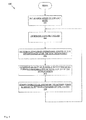
- Fig. 8 is a flow chart illustration of a method of operating an aircraft monitoring system.
- Fig. 9 is a schematic illustration of an exemplary embodiment of an aircraft monitoring system.
- Fig. 10 is a flow chart illustration of an exemplary embodiment of a method of operating an aircraft monitoring system.
- Fig. 11 is a flow chart illustration of an exemplary embodiment of a method of operating an aircraft monitoring system.
- Fig. 12 is a graphical illustration of an exemplary embodiment of a sensor of a sensor node that includes one or more stable operating states.
- Fig. 13 is a schematic illustration of an exemplary embodiment of an aircraft monitoring system.
- an exemplary embodiment of a system 100 for monitoring an aircraft includes one or more sensors nodes 102 that are operably coupled to a central controller 104 by a network 106.
- the sensor nodes 102 are distributed within an aircraft 108 for monitoring one or more operational states of the aircraft that may, for example, include stresses, strains, temperatures, and pressures.
- one or more of the sensor nodes 102 communicate the operational states of the aircraft 108 to the central controller 106 that is housed within the aircraft using, for example, a network 106 that may, for example, include a hard wired, fiber optic, infra red, radio frequency, packet data, acoustic, or other communication pathway.
- each sensor node 102 includes a power supply 102a that is adapted to scavange energy from the immediate environment.
- the power supply 102a may, for example, scavenge electromagnetic energy, solar energy, radio-frequency energy, vibrational energy, heat energy, wind energy, radiated electromagnetic and/or other forms of energy from the environment.
- the power supply 102a further includes a rechargeable battery 102aa operably coupled thereto. In this manner, short bursts of energy that may be scavenged can be scavenged by the power supply 102a and stored for later use in the battery 102aa.
- the power supply 102a is operably coupled, and supplies power, to a communication link 102b, a switch 102c, a micro-controller 102d, a signal conditioner 102e, a sensor 102f, a switch 102g, a switch 102h, and a memory 102i.
- the communication link 102b is also operably coupled to the switch 102c and adapted to transmit and receive communication signals between the sensor node 102 and the network 106. In this manner, the sensor node 102 may communicate with other sensor nodes and the central controller 104.
- the switch 102c is also operably coupled to the communication link 102b and the micro-controller 102d and adapted to be controlled by the micro-controller to thereby communications between the communication link and the micro-controller.
- the micro-controller 102d may operate the switch to prevent communication between the communication link and the micro-controller.
- the micro-controller 102d is also operably coupled to the communication link 102b, the switch 102c, the signal conditioner 102e, the sensor 102f, and the switch 102g for monitoring and controlling the operation of each.
- the micro-controller 102d may include, for example, a conventional general purpose programmable controller.
- the signal conditioner 102e is also operably coupled to the micro-controller 102d and the sensor 102 and adapted to condition signals transmitted by the sensor before they are further processed by the micro-controller.
- the signal conditioner 102e may, for example, include one or more conventional signal processing elements such as, for example, filters, amplifiers, and analog to digital converters.
- the senor 102f is also operably coupled to the signal conditioner 102e and the switch 102g and adapted to sense one or more operating conditions of the aircraft 108 in the immediate environment.
- the sensor 102f may include, for example, one or more of the following: a strain gauge, a stress sensor, a temperature gauge, a pressure gauge, a radiation detector, a radar detector, a chemical sensor, a corrosion sensor and/or a detector of electromagnetic energy.
- the switch 102g is also operably coupled to the micro-controller 102d and the sensor 102f and adapted to control the operation of the sensor under the controller of the micro-controller. In this manner, in the event that the micro-controller 102d determines that the sensor 102f should not operate such as, for example, if the sensor node 102 lacks sufficient power, the micro-controller may operate the switch 102g to prevent power from being supplied by the power supply 102a to the sensor.
- the switch 102h is also operably coupled to the micro-controller 102d and the communication link 102b and adapted to control the operation of the communication link under the controller of the micro-controller.
- the micro-controller 102d determines that the communication link 102b should not operate such as, for example, if the sensor node 102 lacks sufficient power
- the micro-controller may operate the switch 102h to prevent power from being supplied by the power supply 102a to the communication link.
- the memory 102i is also coupled to the micro-controller 102d in order to store the operating system of the sensor node 102 as well as other operating parameters and measurements taken by the sensor 102f.
- the memory 102i may, for example, include one or more conventional memory devices such as, for example, DRAMS, Flash memory, optical storage, hard disk drive, or other memory devices.
- the memory 102i is adapted to store at least one of the mechanical, electrical, chemical, bistable, or multi-stable states of the sensor 102f.
- one or more of the sensor nodes 102 of the system 100 implement a method 400 of operating in which, in 402, the sensor node determines if there is any power available to the sensor node. If there is any power available to the sensor node 102, then the sensor node determines if there is enough power available to the sensor node to permit the sensor node to execute at least one operation in 404.
- the sensor node 102 gets a listing of the possible operations given the amount of available power in 406.
- the sensor node 102 then gets a listing of the current and next operational states for the sensor node in 408.
- the sensor node 102 determines if the next operational states of the sensor node are included in the possible operations given the amount of available power in 410. If the next operational states of the sensor node 102 are included in the possible operations given the amount of available power, then the sensor node executes the next operational states that are possible to execute given the amount of available power in 412.
- one or more of the sensor nodes 102 of the system 100 implement a method 500 of operating in which, in 502, the sensor node determines if there is any power available to the sensor node. If there is any power available to the sensor node 102, then the sensor node determines if there is enough power available to the sensor node to permit the sensor node to execute at least one operation in 504.
- the sensor node 102 gets a listing of the possible operations given the amount of available power in 506.
- the sensor node 102 then gets a listing of the current and next operational states for the sensor node in 508.
- the sensor node 102 determines if the next operational states of the sensor node are included in the possible operations given the amount of available power in 510. If the next operational states of the sensor node 102 are included in the possible operations given the amount of available power, then the sensor node executes the next operational states, based upon their pre-determined priority, that are possible to execute given the amount of available power in 512.
- an exemplary embodiment of a system 600 for monitoring an aircraft is substantially identical in design and operation as the system 100 with the addition of a power dispenser and conditioner 602 that is operably coupled to a source of raw power 604, a power manager 606, a power allocator 608.
- the source of raw power 608 may include one or more of the power supplies 102a of one or more of the sensor nodes 102.
- the power dispenser and conditioner 602 is adapted to receive time varying raw power, P(t) raw , from the source of raw power 604, condition the raw power, and then transmit time varying available power, P(t) avail , to the power allocator 608.
- the power dispenser and conditioner 602 includes one or more elements for conditioning the raw power such as, for example, a rectifier, a filter, and a regulator.
- the power manager 606 includes a power monitor 606a and a power controller 606b.
- the power monitor 606a is operably coupled to the output of the power dispenser and conditioner 602 for monitoring the available power, P(t) avail .
- the power monitor 606a is also operably coupled to the power controller 606b for communicating the available power, P(t) avail , to the power controller.
- the power controller 606b is also operably coupled to the power allocator 608 for controlling the operation of the power allocator.
- the power allocator 608 includes one or more allocators 608i that are each coupled to one or more elements of the sensor node 102 for controllably supplying power to the corresponding elements of the sensor node. In this manner, the power manager 606 and the power allocator 608 collectively determine the power available to the sensor node 102 and then allocate the available power to the elements of the sensor node.
- the system 600 may implement one or more aspects of the methods 400 and 500, described and illustrated above with reference to Figs. 4a , 4b , 5a , and 5b .
- the elements and functionality of the power dispenser and conditioner 602, the raw power source 604, the power manager 606, and the power allocator 608 may be provided within one or more of the sensor nodes 102 and/or provided within the central controller 104.
- an exemplary embodiment of a system 700 for monitoring an aircraft is substantially identical in design and operation as the system 600 except that the power allocator 608 is omitted and the functionality formerly provided by the power allocator is provided by the micro-controller 102d within the sensor nodes 102.
- the power controller 606b is operably coupled to the micro-controller 102d of the sensor node 102 for directing the allocation of the available power by the micro-controller to the elements of the sensor node.
- the system 700 may implement one or more aspects of the methods 400 and 500, described and illustrated above with reference to Figs. 4a , 4b , 5a , and 5b .
- the elements and functionality of the power dispenser and conditioner 602, the raw power source 604, and the power manager 606 may be provided within one or more of the sensor nodes 102 and/or provided within the central controller 104.
- one or more of the systems 100, 600, and 700 may implement a method 800 of operating in which, in 802, the sensor nodes 102 are placed into a default mode of operation which may, for example, include a sleep mode in which the sensor node is inactive, a fully active mode in which the sensor node is fully active, or one or more intermediate active modes in which the sensor node has functionality that is less than in the fully active mode.
- the system, 100, 600, or 700 will then determine the amount of power available to the system.
- the system, 100, 600, or 700 will then determine the available operational states of the sensor nodes 102 of the system given the amount of power available to the system.
- the system, 100, 600, or 700 will then determine the quality of the possible monitoring of the aircraft 108 given the available operational states of the sensor nodes 102 of the system given the amount of power available to the system.
- the quality of the possible monitoring of the aircraft 108 may be a function of what monitoring is adequate based upon the operating envelope and actual operating condition of the aircraft. For example, when the aircraft 108 is cruising at high altitudes with minimal turbulence, the level of detail and sampling rate in the monitored conditions may be less than when the aircraft is climbing to, or diving from, altitude with heavy turbulence.
- the system, 100, 600, or 700 will then modify the operational states of the sensor nodes 102 in order to optimize one or more of: 1) the available operational states of the sensor nodes, 2) the volume of data collected by the sensor nodes, 3) the sampling rate of the data collected by the sensor nodes, 4) the communication throughput of data within the network 106, and/or 5) the quality of the possible monitoring.
- the switches, 102c, 102g and 102h may be operated by the micro-controller 102d to place the sensor node 102 in a sleep mode by not permitting operation of the communication link 102b and the sensor 102f. In this manner, the use of power by the sensor node 102 is minimized.
- the sensor node 102 may be operated in a sleep mode of operation that may, for example, include a range of sleeping mode that may vary from a deep sleep to a light sleep.
- a sleep mode of operation the sensor node 102 may be completely asleep and then may be awakened by a watch dog timer, external interrupt, or other alert.
- a light sleep mode of operation some of the functionality of the sensor node 102 may be reduced.
- the functionality of the sensor node 102 will range from a light sleep to a deep sleep.
- one or more of the elements and functionality of the power dispenser and conditioner 602, the raw power source 604, the power manager 606, and the power allocator 608 may be provided within a sensor node 102, within one or more groups of sensor nodes, and/or within the central controller 104.
- one or more of the elements and functionality of the raw power source 604 may be provided within a single sensor node 102, within one or more groups of sensor nodes, or by all of the sensor nodes.
- the power supply 102a in each of the sensor nodes 102 within one of the systems, 100, 600 or 700 is a solar cell, then the level of solar energy at each sensor node 102 will vary as a function of its location on the aircraft 108.
- the allocation of power within the sensor nodes 102 of the systems, 100, 600 and 700 will determine the mapping of the power generated by the sensor nodes and then allocate power among the sensor nodes in order to optimize the operation of the systems in monitoring the aircraft 108.
- one or more of the sensor nodes 102 may provide one or more of the elements and functionality of the central controller 104.
- one or more of the systems 100, 600 and 700 may be operated to provide an optimal quality of the possible monitoring of the aircraft 108 by placing one or more determined sensor nodes 102 into a sleep mode, even in the presence of adequate power to operate the determined sensor nodes if the systems determine that the optimal quality of the possible monitoring of the aircraft can still be achieved.
- the determined sensor nodes 102 placed into a sleep mode may do one or more of: store power or store data within the determined sensor node.
- data may be warehoused within a sensor node 102 for later use and/or power may be stored within the sensor node for later use.
- one or more of the systems 100, 600 and 700 may be operated to place one or more determined sensor nodes 102 into a sleep mode if the data for the determined sensor node may be extrapolated using the data available for adjacent sensor nodes.
- an exemplary embodiment of a system 900 for monitoring an aircraft is substantially identical in design and operation as the system 100 except that an energy radiator 902 is positioned proximate the aircraft 108 and a central controller 904 is operably coupled to the network 106.
- the energy radiator 902 includes one or more radiators of energy such as, for example, electromagnetic energy, solar energy, radio-frequency energy, vibrational energy, heat energy, and/or wind energy. In this manner, the energy radiator 902 may permit the power supplies 102a of the sensor nodes 102 to scavenge energy for operating the sensor nodes from the energy radiated by the energy radiator 902.
- the central controller 904 is operably coupled to the network 106 in order to monitor and control the operation of the sensor nodes 102.
- the central controller 904 may include a plurality of central controllers positioned proximate the aircraft 100.
- the system 900 implements a method 1000 of monitoring an aircraft in which, in 1002, selected ones of the sensor nodes 102 are radiated with energy by operating the energy radiator 902.
- the amount of energy radiated in 1002 is selected to provide at least a threshold level of energy that may be scavenged by the selected sensor nodes 102 thereby permitting a predetermined level of desired functionality to be achieved by the sensor nodes.
- the selected ones of the sensor nodes 102 scavenge the radiated energy using the power supplies 102.
- at least some of the scavenged radiated power is stored in a power storage battery provided in at least some of the power supplies. In this manner, a relatively short burst of radiated energy may provide functionality of the selected sensors nodes 102 for an extended period of time.
- the method 1000 is implemented as part of a static test of the aircraft 108 while the aircraft is housed within a hangar.
- the energy radiator 902 may radiate electromagnetic energy using a planar wave whose energy level does not decay substantially with distance.
- the energy radiator 902 may include a phased array antenna for radiating energy.
- the energy radiator 902 may include an arbitrarily large antenna and/or one or more directional antennas.
- the energy radiator 902 may radiate a large enough pulse of energy such that the batteries 102aa of the power supplies 102 of the sensor nodes 102 are fully charged such that continued static testing of the aircraft 108 may continue with or without the need for further radiation of energy to the sensor nodes.
- the energy radiator 902 may include a light source operably coupled to a leaky fiber optic cable or light pipe that is positioned proximate the sensor nodes 102 to which it is desired to radiate energy.
- the energy radiator 902 may include a source of thermal energy that may create temperature gradients within the aircraft 108 that may be used by the power supplies 102a of the sensor nodes 102 to generate energy.
- the energy radiated by the energy radiator 902 is selected to include forms of energy that will not effect the structure and/or the measurements to be taken of the aircraft 100.
- the system 100 implements a method 1100 of monitoring an aircraft in which, in 1102, the sensor nodes 102 scavenge sufficient energy from the local environment to permit the sensors 102f of the sensor nodes to sense one or more operating conditions and store the measured operating condition within the sensor and/or the memory 102i.
- the sensors 102f of the sensor nodes 102 recognize that a threshold measured value has been obtained and thereby latch to that sensed value
- the sensors 102f of the sensor nodes 102 are provided with one or more stable operating states that are each reflective of a value of an operating condition.
- one or more of the sensors 102f of the sensor nodes 102 may include an initial operating state S 0 .
- the operational state may then change to a stable sensed state S 1 .
- the sensor 102f of the sensor node 102 would remain in this stable latched operational state unless and until another event reflective of a change in operating conditions, which would include some form of input energy to the sensor 102f, occurred which would move the sensor to a new stable operational state S2. In this manner, the sensor 102f of the sensor 102 would latch onto the sensed operational state and the sensor could be a mechanical latch and/or an electronic latch.
- the number of stable operational states could be any value and such value could determine the level of granularity in the sensor 102f.
- the number of stable operational states also may be used to provide an electrical and/or mechanical analog to digital converter in which the number of stable operational states of the sensor 102f determines the number of levels in the analog to digital converter.
- the sensors 102f of one or more of the sensor nodes 102 are further adapted to stored measure values of operating conditions using the energy associated with the operating condition itself. In this manner, the sensors 102f are able to store stored measure values of operating conditions using the energy associated with the operating condition for indefinite periods of time.
- the sensor 102f may include one or more stable operating states that are each entered into by injecting energy into the sensor, where the injected energy is the operating condition being measured.
- sensor nodes 102 are then radiated with energy in sufficient amounts to permit the sensor nodes to transmit the stored measurements and to reset the sensors 102f.
- the sensor nodes 102 are radiated with energy in sufficient amounts to permit the sensor nodes to transmit the stored measurements by operating an energy radiator 1302 proximate the sensor nodes.
- the design and operation of the energy radiator 1302 is substantially the same as the energy radiator 902.
- the sensor nodes 102 scavenge the radiated energy using the power supplies 102.
- at least some of the scavenged radiated power is stored in a power storage battery provided in at least some of the power supplies. In this manner, a relatively short burst of radiated energy may provide functionality of the selected sensors nodes 102 for an extended period of time.
- the sensor nodes 102 scavenge the radiated energy using the power supplies 102 in sufficient amount to permit the sensor nodes to transmit the stored measurements and to reset the sensor 102f.
- the sensor nodes 102 determine whether to transmit the stored measurements or, in the alternative, to transmit the stored measurements and then reset the sensor 102f.
- each sensor 102 will be programmed by a user of the system 100 in order to determine which action should be taken.
- the desired action to be taken may be altered by downloading instructions to the sensor nodes 102 and/or may be adaptively determined as a function of the type or location of the sensor 102f of the sensor node, the magnitude of the stored measurements, or other factors.
- the sensor node will only transmit the stored measurements to one or more of the central controllers 104.
- the transmission of the stored measurements by the sensor node may be a singlecast or multicast transmission, and may, for example, be transmitted using data packets protocols.
- the sensor node will transmit the stored measurements to one or more of the central controllers 104 and then the sensor node 102 will then reset the associated sensor 102f in 1114.
- the transmission of the stored measurements by the sensor node may be a singlecast or multicast transmission, and may, for example, be transmitted using data packets protocols.
- the sensor 102 node 102 will reset the sensor 102f by, for example, resetting the operational state of the sensor to an earlier operational state.
- the sensors 102 and/or the central controllers 104 may transmit the stored measurements to one or more external central controllers 1304.
- the energy radiator 1302 may include, or at least be operably coupled to, the central controller 1304.
- a portable device that may include both the energy radiator 1302 and the central controller 1304 may be used to wand over selected sensor nodes 102 to thereby interrogate the sensor nodes, capture the stored measurements contained therein, and, if required, also reset the sensors 102f in one or more of the selected sensor nodes 102.
- one or more of the central controllers 104 may send an acknowledgement to the sensor node 102 that transmitted the stored measurements and, in an exemplary embodiment, upon the receipt of the acknowledgement by the sensor node, the sensor node will reset the sensor node's operational state.
- the method 1100 may be used, for example, to provide a regular diagnostic program for the aircraft 108 by mounting the energy radiator 1302 and the central controller 1304 at a fixed location such as, for example, in the ceiling of an aircraft hangar. Then, as the aircraft 108 is moved into or out of the hangar, the stored measurements within the sensors 102f of the sensor nodes 102 may be extracted for processing by the central controller 1304 to determine the health of the aircraft.
- the method 1100 may be used, for example, to provide a regular diagnostic program for a carrier based aircraft 108 by mounting the energy radiator 1302 and the central controller 1304 at a fixed location such as, for example, the aircraft elevator on the carrier. Then, as the aircraft 108 is moved onto or off of the deck of the carrier, the stored measurements within the sensors 102f of the sensor nodes 102 may be extracted for processing by the central controller 1304 to determine the health of the carrier based aircraft.
Abstract
A distributed monitoring system for monitoring one or more operating conditions of a structure, comprising one or more sensor nodes coupled to the structure, each sensor node comprising a power supply adapted to harvest energy directed at the power supply, a sensor operably coupled to the power supply for sensing one or more operating conditions of the structure in the environment; and a communications interface operably coupled to the power supply and the sensor for communicating the sensed operating conditions of the structure, a communication network operably coupled to the sensor nodes, one or more controllers operably coupled to the communication network for monitoring the sensor nodes, and an energy radiator positioned proximate the structure adapted to radiate energy at the power supplies of the sensor nodes.
Description
- The present application is related to patent application serial no.
12/208,222 - This disclosure relates to distributed monitoring systems for a structure.
- According to a first aspect of the invention w provide a distributed monitoring system for monitoring one or more operating conditions of a structure, comprising one or more sensor nodes coupled to the structure, each sensor node comprising a power supply adapted to scavenge energy directed at the power supply, a sensor operably coupled to the power supply for sensing one or more operating conditions of the structure in the environment; and a communications interface operably coupled to the power supply and the sensor for communicating the sensed operating conditions of the structure, a communication network operably coupled to the sensor nodes, one or more controllers operably coupled to the communication network for monitoring the sensor nodes, and an energy radiator positioned proximate the structure adapted to radiate energy at the power supplies of the sensor nodes.
- One or more of the sensor nodes may comprise a rechargeable battery operably coupled to the power supply.
- One or more of the sensor nodes may comprise a memory operably coupled to the sensor.
- The memory may comprise one or more of the following states of the sensor: mechanical, electrical, chemical, bistable, and multi-stable.
- The power supply of one or more of the sensor nodes may be adapted to scavenge enough directed energy to permit the sensor of the corresponding sensor node to sense one or more operating conditions.
- The power supply of one or more of the sensor nodes may be adapted to scavenge enough directed energy to permit the sensor of the corresponding sensor node to sense one or more operating conditions and reset an operating state of the sensor of the corresponding sensor node
- The power supply of one or more of the sensor nodes may be adapted to scavenge enough directed energy to permit the sensor of the corresponding sensor node to sense one or more operating conditions and provides power to enable to reset an operating state of the sensor of the corresponding sensor node as directed by one or more of the controllers.
- The sensor of one or more of the sensor nodes may comprise at least one stable operating state representative of a corresponding measurement value of an operating condition.
- The energy radiator and one or more of the controllers may be positioned proximate the structure.
- The energy radiator may comprise a radiator of one or more of the following: radiofrequency energy, optical energy, and thermal energy.
- The structure may comprise an aircraft.
- According to a second aspect of the invention, we provide a method of operating a system for monitoring one or more operating conditions of a structure, comprising providing sensor nodes at locations around the structure for sensing operating conditions of the structure, directing radiated energy at one or more of the sensor nodes, scavenging the radiated energy at one or more of the sensor nodes, and using the scavenged energy at one or more of the sensor nodes to transmit sensed operating conditions from one or more of the sensor nodes.
- One or more of the sensor nodes maystore a measurement of one or more sensed operating conditions.
- The system may further comprise using the scavenged energy at one or more of the sensor nodes to reset an operating condition of a sensor of one or more of the sensor nodes.
- The structure may comprise an aircraft.
- One or more of the sensor nodes may use energy associated with the sensed operating condition to store a measurement of the sensed operating condition.
-
Fig. 1 is an illustration of an exemplary embodiment of an aircraft monitoring system. -
Fig. 2 is a schematic illustration of the aircraft monitoring system ofFig. 1 . -
Fig. 3 is a schematic illustration of an exemplary embodiment of sensor nodes of the aircraft monitoring system ofFig. 2 . -
Figs. 4a and4b are flow chart illustrations of an exemplary embodiment of a method of operating the sensor nodes ofFig. 3 . -
Figs. 5a and5b are flow chart illustrations of an exemplary embodiment of a method of operating the sensor nodes ofFig. 3 . -
Fig. 6 is a schematic illustration of an exemplary embodiment of an aircraft monitoring system. -
Fig. 7 is a schematic illustration of an exemplary embodiment of an aircraft monitoring system. -
Fig. 8 is a flow chart illustration of a method of operating an aircraft monitoring system. -
Fig. 9 is a schematic illustration of an exemplary embodiment of an aircraft monitoring system. -
Fig. 10 is a flow chart illustration of an exemplary embodiment of a method of operating an aircraft monitoring system. -
Fig. 11 is a flow chart illustration of an exemplary embodiment of a method of operating an aircraft monitoring system. -
Fig. 12 is a graphical illustration of an exemplary embodiment of a sensor of a sensor node that includes one or more stable operating states. -
Fig. 13 is a schematic illustration of an exemplary embodiment of an aircraft monitoring system. - In the drawings and description that follows, like parts are marked throughout the specification and drawings with the same reference numerals, respectively. The drawings are not necessarily to scale. Certain features of the invention may be shown exaggerated in scale or in somewhat schematic form and some details of conventional elements may not be shown in the interest of clarity and conciseness. The present invention is susceptible to embodiments of different forms. Specific embodiments are described in detail and are shown in the drawings, with the understanding that the present disclosure is to be considered an exemplification of the principles of the invention, and is not intended to limit the invention to that illustrated and described herein. It is to be fully recognized that the different teachings of the embodiments discussed below may be employed separately or in any suitable combination to produce desired results. The various characteristics mentioned above, as well as other features and characteristics described in more detail below, will be readily apparent to those skilled in the art upon reading the following detailed description of the embodiments, and by referring to the accompanying drawings.
- Referring to
Figs. 1-3 , an exemplary embodiment of asystem 100 for monitoring an aircraft includes one ormore sensors nodes 102 that are operably coupled to acentral controller 104 by anetwork 106. In an exemplary embodiment, thesensor nodes 102 are distributed within anaircraft 108 for monitoring one or more operational states of the aircraft that may, for example, include stresses, strains, temperatures, and pressures. In an exemplary embodiment, one or more of thesensor nodes 102 communicate the operational states of theaircraft 108 to thecentral controller 106 that is housed within the aircraft using, for example, anetwork 106 that may, for example, include a hard wired, fiber optic, infra red, radio frequency, packet data, acoustic, or other communication pathway. - In an exemplary embodiment, each
sensor node 102 includes apower supply 102a that is adapted to scavange energy from the immediate environment. In an exemplary embodiment, thepower supply 102a may, for example, scavenge electromagnetic energy, solar energy, radio-frequency energy, vibrational energy, heat energy, wind energy, radiated electromagnetic and/or other forms of energy from the environment. In an exemplary embodiment, thepower supply 102a further includes a rechargeable battery 102aa operably coupled thereto. In this manner, short bursts of energy that may be scavenged can be scavenged by thepower supply 102a and stored for later use in the battery 102aa. In an exemplary embodiment, thepower supply 102a is operably coupled, and supplies power, to acommunication link 102b, aswitch 102c, a micro-controller 102d, asignal conditioner 102e, a sensor 102f, a switch 102g, aswitch 102h, and a memory 102i. - In an exemplary embodiment, the
communication link 102b is also operably coupled to theswitch 102c and adapted to transmit and receive communication signals between thesensor node 102 and thenetwork 106. In this manner, thesensor node 102 may communicate with other sensor nodes and thecentral controller 104. - In an exemplary embodiment, the
switch 102c is also operably coupled to thecommunication link 102b and the micro-controller 102d and adapted to be controlled by the micro-controller to thereby communications between the communication link and the micro-controller. In this manner, in the event that the micro-controller 102d determines that communication should not occur between thecommunication link 102b and the micro-controller such as, for example, if thesensor node 102 lacks sufficient power, the micro-controller may operate the switch to prevent communication between the communication link and the micro-controller. - In an exemplary embodiment, the micro-controller 102d is also operably coupled to the
communication link 102b, theswitch 102c, thesignal conditioner 102e, the sensor 102f, and the switch 102g for monitoring and controlling the operation of each. In an exemplary embodiment, the micro-controller 102d may include, for example, a conventional general purpose programmable controller. - In an exemplary embodiment, the
signal conditioner 102e is also operably coupled to the micro-controller 102d and thesensor 102 and adapted to condition signals transmitted by the sensor before they are further processed by the micro-controller. In an exemplary embodiment, thesignal conditioner 102e may, for example, include one or more conventional signal processing elements such as, for example, filters, amplifiers, and analog to digital converters. - In an exemplary embodiment, the sensor 102f is also operably coupled to the
signal conditioner 102e and the switch 102g and adapted to sense one or more operating conditions of theaircraft 108 in the immediate environment. In an exemplary embodiment, the sensor 102f may include, for example, one or more of the following: a strain gauge, a stress sensor, a temperature gauge, a pressure gauge, a radiation detector, a radar detector, a chemical sensor, a corrosion sensor and/or a detector of electromagnetic energy. - In an exemplary embodiment, the switch 102g is also operably coupled to the micro-controller 102d and the sensor 102f and adapted to control the operation of the sensor under the controller of the micro-controller. In this manner, in the event that the micro-controller 102d determines that the sensor 102f should not operate such as, for example, if the
sensor node 102 lacks sufficient power, the micro-controller may operate the switch 102g to prevent power from being supplied by thepower supply 102a to the sensor. - In an exemplary embodiment, the
switch 102h is also operably coupled to the micro-controller 102d and thecommunication link 102b and adapted to control the operation of the communication link under the controller of the micro-controller. In this manner, in the event that the micro-controller 102d determines that thecommunication link 102b should not operate such as, for example, if thesensor node 102 lacks sufficient power, the micro-controller may operate theswitch 102h to prevent power from being supplied by thepower supply 102a to the communication link. - In an exemplary embodiment, the memory 102i is also coupled to the micro-controller 102d in order to store the operating system of the
sensor node 102 as well as other operating parameters and measurements taken by the sensor 102f. The memory 102i may, for example, include one or more conventional memory devices such as, for example, DRAMS, Flash memory, optical storage, hard disk drive, or other memory devices. In an exemplary embodiment, the memory 102i is adapted to store at least one of the mechanical, electrical, chemical, bistable, or multi-stable states of the sensor 102f. - Referring now to
Figs. 4a and4b , in an exemplary embodiment, one or more of thesensor nodes 102 of thesystem 100 implement amethod 400 of operating in which, in 402, the sensor node determines if there is any power available to the sensor node. If there is any power available to thesensor node 102, then the sensor node determines if there is enough power available to the sensor node to permit the sensor node to execute at least one operation in 404. - If there is enough power available to permit the
sensor node 102 to execute at least one operation, then the sensor gets a listing of the possible operations given the amount of available power in 406. Thesensor node 102 then gets a listing of the current and next operational states for the sensor node in 408. - The
sensor node 102 then determines if the next operational states of the sensor node are included in the possible operations given the amount of available power in 410. If the next operational states of thesensor node 102 are included in the possible operations given the amount of available power, then the sensor node executes the next operational states that are possible to execute given the amount of available power in 412. - Referring now to
Figs. 5a and5b , in an exemplary embodiment, one or more of thesensor nodes 102 of thesystem 100 implement amethod 500 of operating in which, in 502, the sensor node determines if there is any power available to the sensor node. If there is any power available to thesensor node 102, then the sensor node determines if there is enough power available to the sensor node to permit the sensor node to execute at least one operation in 504. - If there is enough power available to permit the
sensor node 102 to execute at least one operation, then the sensor gets a listing of the possible operations given the amount of available power in 506. Thesensor node 102 then gets a listing of the current and next operational states for the sensor node in 508. - The
sensor node 102 then determines if the next operational states of the sensor node are included in the possible operations given the amount of available power in 510. If the next operational states of thesensor node 102 are included in the possible operations given the amount of available power, then the sensor node executes the next operational states, based upon their pre-determined priority, that are possible to execute given the amount of available power in 512. - Referring now to
Fig. 6 , an exemplary embodiment of asystem 600 for monitoring an aircraft is substantially identical in design and operation as thesystem 100 with the addition of a power dispenser andconditioner 602 that is operably coupled to a source ofraw power 604, apower manager 606, apower allocator 608. - In an exemplary embodiment, the source of
raw power 608 may include one or more of thepower supplies 102a of one or more of thesensor nodes 102. In an exemplary embodiment, the power dispenser andconditioner 602 is adapted to receive time varying raw power, P(t)raw, from the source ofraw power 604, condition the raw power, and then transmit time varying available power, P(t)avail, to thepower allocator 608. In an exemplary embodiment, the power dispenser andconditioner 602 includes one or more elements for conditioning the raw power such as, for example, a rectifier, a filter, and a regulator. - In an exemplary embodiment, the
power manager 606 includes apower monitor 606a and apower controller 606b. In an exemplary embodiment, thepower monitor 606a is operably coupled to the output of the power dispenser andconditioner 602 for monitoring the available power, P(t)avail. In an exemplary embodiment, thepower monitor 606a is also operably coupled to thepower controller 606b for communicating the available power, P(t)avail, to the power controller. In an exemplary embodiment, thepower controller 606b is also operably coupled to thepower allocator 608 for controlling the operation of the power allocator. - In an exemplary embodiment, the
power allocator 608 includes one or more allocators 608i that are each coupled to one or more elements of thesensor node 102 for controllably supplying power to the corresponding elements of the sensor node. In this manner, thepower manager 606 and thepower allocator 608 collectively determine the power available to thesensor node 102 and then allocate the available power to the elements of the sensor node. - In an exemplary embodiment, the
system 600 may implement one or more aspects of themethods Figs. 4a ,4b ,5a , and5b . In an exemplary embodiment, the elements and functionality of the power dispenser andconditioner 602, theraw power source 604, thepower manager 606, and thepower allocator 608 may be provided within one or more of thesensor nodes 102 and/or provided within thecentral controller 104. - Referring now to
Fig. 7 , an exemplary embodiment of asystem 700 for monitoring an aircraft is substantially identical in design and operation as thesystem 600 except that thepower allocator 608 is omitted and the functionality formerly provided by the power allocator is provided by the micro-controller 102d within thesensor nodes 102. - In particular, in the
system 700, thepower controller 606b is operably coupled to the micro-controller 102d of thesensor node 102 for directing the allocation of the available power by the micro-controller to the elements of the sensor node. - In an exemplary embodiment, the
system 700 may implement one or more aspects of themethods Figs. 4a ,4b ,5a , and5b . In an exemplary embodiment, the elements and functionality of the power dispenser andconditioner 602, theraw power source 604, and thepower manager 606 may be provided within one or more of thesensor nodes 102 and/or provided within thecentral controller 104. - Referring now to
Fig. 8 , in an exemplary embodiment, one or more of thesystems method 800 of operating in which, in 802, thesensor nodes 102 are placed into a default mode of operation which may, for example, include a sleep mode in which the sensor node is inactive, a fully active mode in which the sensor node is fully active, or one or more intermediate active modes in which the sensor node has functionality that is less than in the fully active mode. In 804, the system, 100, 600, or 700, will then determine the amount of power available to the system. In an exemplary embodiment, in 806, the system, 100, 600, or 700, will then determine the available operational states of thesensor nodes 102 of the system given the amount of power available to the system. - In an exemplary embodiment, in 808, the system, 100, 600, or 700, will then determine the quality of the possible monitoring of the
aircraft 108 given the available operational states of thesensor nodes 102 of the system given the amount of power available to the system. In an exemplary embodiment, the quality of the possible monitoring of theaircraft 108 may be a function of what monitoring is adequate based upon the operating envelope and actual operating condition of the aircraft. For example, when theaircraft 108 is cruising at high altitudes with minimal turbulence, the level of detail and sampling rate in the monitored conditions may be less than when the aircraft is climbing to, or diving from, altitude with heavy turbulence. - In an exemplary embodiment, in 810, the system, 100, 600, or 700, will then modify the operational states of the
sensor nodes 102 in order to optimize one or more of: 1) the available operational states of the sensor nodes, 2) the volume of data collected by the sensor nodes, 3) the sampling rate of the data collected by the sensor nodes, 4) the communication throughput of data within thenetwork 106, and/or 5) the quality of the possible monitoring. - In an exemplary embodiment, during the operation of the systems, 100, 600 and/or 700, the switches, 102c, 102g and 102h, may be operated by the micro-controller 102d to place the
sensor node 102 in a sleep mode by not permitting operation of thecommunication link 102b and the sensor 102f. In this manner, the use of power by thesensor node 102 is minimized. - In an exemplary embodiment, during the operation of the systems, 100, 600 and/or 700, the
sensor node 102 may be operated in a sleep mode of operation that may, for example, include a range of sleeping mode that may vary from a deep sleep to a light sleep. In an exemplary embodiment, in a deep sleep mode of operation, thesensor node 102 may be completely asleep and then may be awakened by a watch dog timer, external interrupt, or other alert. In an exemplary embodiment, in a light sleep mode of operation, some of the functionality of thesensor node 102 may be reduced. In an exemplary embodiment, in one or more intermediate sleeping modes of operation, the functionality of thesensor node 102 will range from a light sleep to a deep sleep. - In an exemplary embodiment, in one or more of the
systems conditioner 602, theraw power source 604, thepower manager 606, and thepower allocator 608 may be provided within asensor node 102, within one or more groups of sensor nodes, and/or within thecentral controller 104. - In an exemplary embodiment, in one or more of the systems, 100, 600 and 700, one or more of the elements and functionality of the
raw power source 604 may be provided within asingle sensor node 102, within one or more groups of sensor nodes, or by all of the sensor nodes. For example, if thepower supply 102a in each of thesensor nodes 102 within one of the systems, 100, 600 or 700, is a solar cell, then the level of solar energy at eachsensor node 102 will vary as a function of its location on theaircraft 108. In an exemplary embodiment, the allocation of power within thesensor nodes 102 of the systems, 100, 600 and 700, will determine the mapping of the power generated by the sensor nodes and then allocate power among the sensor nodes in order to optimize the operation of the systems in monitoring theaircraft 108. - In an exemplary embodiment, in one or more of the
systems sensor nodes 102 may provide one or more of the elements and functionality of thecentral controller 104. - In an exemplary embodiment, one or more of the
systems aircraft 108 by placing one or moredetermined sensor nodes 102 into a sleep mode, even in the presence of adequate power to operate the determined sensor nodes if the systems determine that the optimal quality of the possible monitoring of the aircraft can still be achieved. In this manner, thedetermined sensor nodes 102 placed into a sleep mode may do one or more of: store power or store data within the determined sensor node. In this manner, data may be warehoused within asensor node 102 for later use and/or power may be stored within the sensor node for later use. - In an exemplary embodiment, one or more of the
systems determined sensor nodes 102 into a sleep mode if the data for the determined sensor node may be extrapolated using the data available for adjacent sensor nodes. - Referring now to
Fig. 9 , an exemplary embodiment of asystem 900 for monitoring an aircraft is substantially identical in design and operation as thesystem 100 except that anenergy radiator 902 is positioned proximate theaircraft 108 and acentral controller 904 is operably coupled to thenetwork 106. - In an exemplary embodiment, the
energy radiator 902 includes one or more radiators of energy such as, for example, electromagnetic energy, solar energy, radio-frequency energy, vibrational energy, heat energy, and/or wind energy. In this manner, theenergy radiator 902 may permit thepower supplies 102a of thesensor nodes 102 to scavenge energy for operating the sensor nodes from the energy radiated by theenergy radiator 902. - In an exemplary embodiment, the
central controller 904 is operably coupled to thenetwork 106 in order to monitor and control the operation of thesensor nodes 102. In an exemplary embodiment, thecentral controller 904 may include a plurality of central controllers positioned proximate theaircraft 100. - Referring to
Fig. 10 , in an exemplary embodiment, thesystem 900 implements amethod 1000 of monitoring an aircraft in which, in 1002, selected ones of thesensor nodes 102 are radiated with energy by operating theenergy radiator 902. In an exemplary embodiment, the amount of energy radiated in 1002 is selected to provide at least a threshold level of energy that may be scavenged by the selectedsensor nodes 102 thereby permitting a predetermined level of desired functionality to be achieved by the sensor nodes. - In 1004, the selected ones of the
sensor nodes 102 scavenge the radiated energy using the power supplies 102. In an exemplary embodiment, at least some of the scavenged radiated power is stored in a power storage battery provided in at least some of the power supplies. In this manner, a relatively short burst of radiated energy may provide functionality of the selectedsensors nodes 102 for an extended period of time. - In an exemplary embodiment, the
method 1000 is implemented as part of a static test of theaircraft 108 while the aircraft is housed within a hangar. - In an exemplary embodiment, the
energy radiator 902 may radiate electromagnetic energy using a planar wave whose energy level does not decay substantially with distance. In an exemplary embodiment, theenergy radiator 902 may include a phased array antenna for radiating energy. In an exemplary embodiment, theenergy radiator 902 may include an arbitrarily large antenna and/or one or more directional antennas. - In an exemplary embodiment, the
energy radiator 902 may radiate a large enough pulse of energy such that the batteries 102aa of the power supplies 102 of thesensor nodes 102 are fully charged such that continued static testing of theaircraft 108 may continue with or without the need for further radiation of energy to the sensor nodes. - In an exemplary embodiment, the
energy radiator 902 may include a light source operably coupled to a leaky fiber optic cable or light pipe that is positioned proximate thesensor nodes 102 to which it is desired to radiate energy. In an exemplary embodiment, theenergy radiator 902 may include a source of thermal energy that may create temperature gradients within theaircraft 108 that may be used by thepower supplies 102a of thesensor nodes 102 to generate energy. - In an exemplary embodiment, the energy radiated by the
energy radiator 902 is selected to include forms of energy that will not effect the structure and/or the measurements to be taken of theaircraft 100. - Referring to
Fig. 11 , in an exemplary embodiment, thesystem 100 implements amethod 1100 of monitoring an aircraft in which, in 1102, thesensor nodes 102 scavenge sufficient energy from the local environment to permit the sensors 102f of the sensor nodes to sense one or more operating conditions and store the measured operating condition within the sensor and/or the memory 102i. In an exemplary embodiment, in 1102, the sensors 102f of thesensor nodes 102 recognize that a threshold measured value has been obtained and thereby latch to that sensed value - In an exemplary embodiment, as illustrated in
Fig. 12 , the sensors 102f of thesensor nodes 102 are provided with one or more stable operating states that are each reflective of a value of an operating condition. For example, as illustrated inFig. 12 , one or more of the sensors 102f of thesensor nodes 102 may include an initial operating state S0. Upon the sensing of an operating condition, which would include some form of input energy to the sensor 102f, the operational state may then change to a stable sensed state S1. The sensor 102f of thesensor node 102 would remain in this stable latched operational state unless and until another event reflective of a change in operating conditions, which would include some form of input energy to the sensor 102f, occurred which would move the sensor to a new stable operational state S2. In this manner, the sensor 102f of thesensor 102 would latch onto the sensed operational state and the sensor could be a mechanical latch and/or an electronic latch. In an exemplary embodiment, the number of stable operational states could be any value and such value could determine the level of granularity in the sensor 102f. In an exemplary embodiment, the number of stable operational states also may be used to provide an electrical and/or mechanical analog to digital converter in which the number of stable operational states of the sensor 102f determines the number of levels in the analog to digital converter. - In an exemplary embodiment, the sensors 102f of one or more of the
sensor nodes 102 are further adapted to stored measure values of operating conditions using the energy associated with the operating condition itself. In this manner, the sensors 102f are able to store stored measure values of operating conditions using the energy associated with the operating condition for indefinite periods of time. For example, as illustrated inFig. 12 , the sensor 102f may include one or more stable operating states that are each entered into by injecting energy into the sensor, where the injected energy is the operating condition being measured. - In an exemplary embodiment, in 1104,
sensor nodes 102 are then radiated with energy in sufficient amounts to permit the sensor nodes to transmit the stored measurements and to reset the sensors 102f. In an exemplary embodiment, in 1104, as illustrated inFig. 13 , thesensor nodes 102 are radiated with energy in sufficient amounts to permit the sensor nodes to transmit the stored measurements by operating anenergy radiator 1302 proximate the sensor nodes. In an exemplary embodiment, the design and operation of theenergy radiator 1302 is substantially the same as theenergy radiator 902. - In an exemplary embodiment, in 1106, the
sensor nodes 102 scavenge the radiated energy using the power supplies 102. In an exemplary embodiment, at least some of the scavenged radiated power is stored in a power storage battery provided in at least some of the power supplies. In this manner, a relatively short burst of radiated energy may provide functionality of the selectedsensors nodes 102 for an extended period of time. In an exemplary embodiment, in 1106, thesensor nodes 102 scavenge the radiated energy using the power supplies 102 in sufficient amount to permit the sensor nodes to transmit the stored measurements and to reset the sensor 102f. - In an exemplary embodiment, in 1108, the
sensor nodes 102 determine whether to transmit the stored measurements or, in the alternative, to transmit the stored measurements and then reset the sensor 102f. In an exemplary embodiment, eachsensor 102 will be programmed by a user of thesystem 100 in order to determine which action should be taken. Alternatively, the desired action to be taken may be altered by downloading instructions to thesensor nodes 102 and/or may be adaptively determined as a function of the type or location of the sensor 102f of the sensor node, the magnitude of the stored measurements, or other factors. - If a
particular sensor node 102 has been instructed to only transmit the stored measurements, then, in 1110, the sensor node will only transmit the stored measurements to one or more of thecentral controllers 104. In an exemplary embodiment, in 1110, the transmission of the stored measurements by the sensor node may be a singlecast or multicast transmission, and may, for example, be transmitted using data packets protocols. - If a
particular sensor node 102 has been instructed to transmit the stored measurements and reset the sensor 102f, then, in 1112, the sensor node will transmit the stored measurements to one or more of thecentral controllers 104 and then thesensor node 102 will then reset the associated sensor 102f in 1114. In an exemplary embodiment, in 1112, the transmission of the stored measurements by the sensor node may be a singlecast or multicast transmission, and may, for example, be transmitted using data packets protocols. In an exemplary embodiment, in 1114, thesensor 102node 102 will reset the sensor 102f by, for example, resetting the operational state of the sensor to an earlier operational state. - In an exemplary embodiment, as illustrated in
Fig. 13 , in 1110 and/or 1112, thesensors 102 and/or thecentral controllers 104 may transmit the stored measurements to one or more externalcentral controllers 1304. In an exemplary embodiment, theenergy radiator 1302 may include, or at least be operably coupled to, thecentral controller 1304. In this manner, a portable device that may include both theenergy radiator 1302 and thecentral controller 1304 may be used to wand over selectedsensor nodes 102 to thereby interrogate the sensor nodes, capture the stored measurements contained therein, and, if required, also reset the sensors 102f in one or more of the selectedsensor nodes 102. - In an exemplary embodiment, after completing 1110 and/or 1112, one or more of the
central controllers 104 may send an acknowledgement to thesensor node 102 that transmitted the stored measurements and, in an exemplary embodiment, upon the receipt of the acknowledgement by the sensor node, the sensor node will reset the sensor node's operational state. - In an exemplary embodiment, the
method 1100 may be used, for example, to provide a regular diagnostic program for theaircraft 108 by mounting theenergy radiator 1302 and thecentral controller 1304 at a fixed location such as, for example, in the ceiling of an aircraft hangar. Then, as theaircraft 108 is moved into or out of the hangar, the stored measurements within the sensors 102f of thesensor nodes 102 may be extracted for processing by thecentral controller 1304 to determine the health of the aircraft. - In an exemplary embodiment, the
method 1100 may be used, for example, to provide a regular diagnostic program for a carrier basedaircraft 108 by mounting theenergy radiator 1302 and thecentral controller 1304 at a fixed location such as, for example, the aircraft elevator on the carrier. Then, as theaircraft 108 is moved onto or off of the deck of the carrier, the stored measurements within the sensors 102f of thesensor nodes 102 may be extracted for processing by thecentral controller 1304 to determine the health of the carrier based aircraft. - It is understood that variations may be made in the above without departing from the scope of the invention. For example, the teachings of the exemplary embodiments may be applied to monitoring an aircraft, a ship, a vehicle, a building, the environment, or any other application in which a distributed monitoring system would provide value. While specific embodiments have been shown and described, modifications can be made by one skilled in the art without departing from the spirit or teaching of this invention. The embodiments as described are exemplary only and are not limiting. Many variations and modifications are possible and are within the scope of the invention. Accordingly, the scope of protection is not limited to the embodiments described, but is only limited by the claims that follow, the scope of which shall include all equivalents of the subject matter of the claims.
Claims (16)
- A distributed monitoring system for monitoring one or more operating conditions of a structure, comprising:one or more sensor nodes coupled to the structure, each sensor node comprising:a power supply adapted to scavenge energy directed at the power supply;a sensor operably coupled to the power supply for sensing one or more operating conditions of the structure in the environment; anda communications interface operably coupled to the power supply and the sensor for communicating the sensed operating conditions of the structure;a communication network operably coupled to the sensor nodes;one or more controllers operably coupled to the communication network for monitoring the sensor nodes; andan energy radiator positioned proximate the structure adapted to radiate energy at the power supplies of the sensor nodes.
- The system of claim 1, wherein one or more of the sensor nodes comprise a rechargeable battery operably coupled to the power supply.
- The system of claim 1 or claim 2, wherein one or more of the sensor nodes comprise a memory operably coupled to the sensor.
- The system of claim 3, wherein the memory comprises one or more of the following states of the sensor: mechanical, electrical, chemical, bistable, and multi-stable.
- The system of any one of the preceding claims, wherein the power supply of one or more of the sensor nodes is adapted to scavenge enough directed energy to permit the sensor of the corresponding sensor node to sense one or more operating conditions.
- The system of claim 5, wherein the power supply of one or more of the sensor nodes is adapted to scavenge enough directed energy to permit the sensor of the corresponding sensor node to sense one or more operating conditions and reset an operating state of the sensor of the corresponding sensor node.
- The system of claim 5, wherein the power supply of one or more of the sensor nodes is adapted to scavenge enough directed energy to permit the sensor of the corresponding sensor node to sense one or more operating conditions and provides power to enable to reset an operating state of the sensor of the corresponding sensor node as directed by one or more of the controllers.
- The system of any one of the preceding claims, wherein the sensor of one or more of the sensor nodes comprises at least one stable operating state representative of a corresponding measurement value of an operating condition.
- The system of any one of the preceding claims, wherein the energy radiator and one or more of the controllers are positioned proximate the structure.
- The system of any one of the preceding claims, wherein the energy radiator comprises a radiator of one or more of the following: radiofrequency energy, optical energy, and thermal energy.
- The system of any one of the preceding claims, wherein the structure comprises an aircraft.
- A method of operating a system for monitoring one or more operating conditions of a structure, comprising:providing sensor nodes at locations around the structure for sensing operating conditions of the structure;directing radiated energy at one or more of the sensor nodes;scavenging the radiated energy at one or more of the sensor nodes; andusing the scavenged energy at one or more of the sensor nodes to transmit sensed operating conditions from one or more of the sensor nodes.
- The method of claim 12, wherein one or more of the sensor nodes store a measurement of one or more sensed operating conditions.
- The method of claim 12 or claim 13, further comprising using the scavenged energy at one or more of the sensor nodes to reset an operating condition of a sensor of one or more of the sensor nodes.
- The method of any one of claims 12 to 14, wherein the structure comprises an aircraft.
- The method of any one of claims 12 to 15, wherein one or more of the sensor nodes use energy associated with the sensed operating condition to store a measurement of the sensed operating condition.
Applications Claiming Priority (1)
| Application Number | Priority Date | Filing Date | Title |
|---|---|---|---|
| US12/331,908 US8098143B2 (en) | 2008-12-10 | 2008-12-10 | Power aware techniques for energy harvesting remote sensor system |
Publications (1)
| Publication Number | Publication Date |
|---|---|
| EP2197151A1 true EP2197151A1 (en) | 2010-06-16 |
Family
ID=41821857
Family Applications (1)
| Application Number | Title | Priority Date | Filing Date |
|---|---|---|---|
| EP09178752A Withdrawn EP2197151A1 (en) | 2008-12-10 | 2009-12-10 | Power aware techniques for energy harvesting remote sensor systems |
Country Status (2)
| Country | Link |
|---|---|
| US (1) | US8098143B2 (en) |
| EP (1) | EP2197151A1 (en) |
Families Citing this family (15)
| Publication number | Priority date | Publication date | Assignee | Title |
|---|---|---|---|---|
| US7861969B2 (en) | 2007-05-24 | 2011-01-04 | The Boeing Company | Shaped composite stringers and methods of making |
| US7879276B2 (en) | 2007-11-08 | 2011-02-01 | The Boeing Company | Foam stiffened hollow composite stringer |
| US8540921B2 (en) | 2008-11-25 | 2013-09-24 | The Boeing Company | Method of forming a reinforced foam-filled composite stringer |
| US8253587B2 (en) * | 2009-02-04 | 2012-08-28 | Lockheed Martin Corporation | Power free remote sensor system data transmissions |
| US8294597B2 (en) * | 2009-02-04 | 2012-10-23 | Lockheed Martin Corporation | Self regulating power conditioner for energy harvesting applications |
| US8500066B2 (en) | 2009-06-12 | 2013-08-06 | The Boeing Company | Method and apparatus for wireless aircraft communications and power system using fuselage stringers |
| US8570152B2 (en) | 2009-07-23 | 2013-10-29 | The Boeing Company | Method and apparatus for wireless sensing with power harvesting of a wireless signal |
| US8617687B2 (en) | 2009-08-03 | 2013-12-31 | The Boeing Company | Multi-functional aircraft structures |
| US8384559B2 (en) * | 2010-04-13 | 2013-02-26 | Silicon Laboratories Inc. | Sensor device with flexible interface and updatable information store |
| US10131419B2 (en) * | 2010-10-15 | 2018-11-20 | Goodrich Corporation | Systems and methods for detecting landing gear ground loads |
| EP3451629A1 (en) * | 2017-08-29 | 2019-03-06 | Terabee S.A.S. | Intelligent hub |
| CN107995632B (en) * | 2017-11-06 | 2021-06-18 | 浙江工业大学 | Passive sensing node deployment scheduling method for ensuring static target detection quality |
| US20190234227A1 (en) * | 2018-01-29 | 2019-08-01 | Siemens Energy, Inc. | Powering generator instrumentation via magnetic induction |
| US11097852B2 (en) | 2018-11-28 | 2021-08-24 | The Boeing Company | Systems and methods for obtaining sensor data indicative of flight characteristics of an aircraft using an acoustically powered sensor unit |
| IT201900006735A1 (en) * | 2019-05-10 | 2020-11-10 | Sacertis S R L | Method of investigation of a structure and procedure to define an optimal method of investigation of the structure itself |
Citations (2)
| Publication number | Priority date | Publication date | Assignee | Title |
|---|---|---|---|---|
| US20050140212A1 (en) | 2002-03-07 | 2005-06-30 | Microstrain, Inc. | Energy harvesting for wireless sensor operation and data transmission |
| US20070114422A1 (en) | 2005-11-23 | 2007-05-24 | Lockheed Martin Corporation | System to monitor the health of a structure, sensor nodes, program product, and related methods |
Family Cites Families (28)
| Publication number | Priority date | Publication date | Assignee | Title |
|---|---|---|---|---|
| US160323A (en) * | 1875-03-02 | Improvement in bill-files | ||
| US92838A (en) * | 1869-07-20 | Improved blacking-cabinet | ||
| US5036465A (en) * | 1989-10-03 | 1991-07-30 | Grumman Aerospace Corporation | Method of controlling and monitoring a store |
| US7103460B1 (en) * | 1994-05-09 | 2006-09-05 | Automotive Technologies International, Inc. | System and method for vehicle diagnostics |
| US5583819A (en) | 1995-01-27 | 1996-12-10 | Single Chip Holdings, Inc. | Apparatus and method of use of radiofrequency identification tags |
| US5757598A (en) * | 1996-12-27 | 1998-05-26 | Tower Manufacturing Corporation | Ground fault circuit interrupter |
| US5986570A (en) | 1997-09-03 | 1999-11-16 | Micron Communications, Inc. | Method for resolving signal collisions between multiple RFID transponders in a field |
| GB9813371D0 (en) | 1998-06-22 | 1998-08-19 | Powell George L | Anti-collision tag apparatus and system |
| US6411199B1 (en) | 1998-08-21 | 2002-06-25 | Keri Systems, Inc. | Radio frequency identification system |
| US6615074B2 (en) | 1998-12-22 | 2003-09-02 | University Of Pittsburgh Of The Commonwealth System Of Higher Education | Apparatus for energizing a remote station and related method |
| US6561040B1 (en) | 1999-01-14 | 2003-05-13 | Lockheed Martin Corporation | Method and apparatus for detecting environmental conditions utilizing micro-electrical mechanical devices |
| US6806808B1 (en) * | 1999-02-26 | 2004-10-19 | Sri International | Wireless event-recording device with identification codes |
| US6617963B1 (en) * | 1999-02-26 | 2003-09-09 | Sri International | Event-recording devices with identification codes |
| US6121880A (en) | 1999-05-27 | 2000-09-19 | Intermec Ip Corp. | Sticker transponder for use on glass surface |
| DE10019539A1 (en) | 2000-04-20 | 2001-10-25 | Abb Research Ltd | Proximity sensor, has wireless power supply with demultiplexer allowing simultaneous power feed and operation |
| EP1299030A2 (en) | 2000-07-10 | 2003-04-09 | Lockheed Martin Corporation | Self energized wireless mems devices |
| DE60116520T2 (en) | 2000-10-10 | 2006-08-31 | Microchips, Inc., Bedford | MICROCHIP RESERVOIR DEVICES WITH WIRELESS TRANSMISSION OF ENERGY AND DATA |
| US6771007B2 (en) | 2002-04-17 | 2004-08-03 | The Boeing Company | Vibration induced perpetual energy resource |
| FR2841089B1 (en) | 2002-06-14 | 2004-07-30 | Sequoias | METHOD OF INDUSTRIAL MANUFACTURE OF ANTENNAS FOR RFID TRANSPONDERS |
| GB0216745D0 (en) | 2002-07-18 | 2002-08-28 | Univ Cardiff | Sensor |
| US20040150529A1 (en) | 2003-01-30 | 2004-08-05 | Benoit Jeffrey T. | Power harvesting sensor for monitoring and control |
| US7079034B2 (en) | 2003-02-03 | 2006-07-18 | Ingrid, Inc. | RFID transponder for a security system |
| US6848616B2 (en) | 2003-03-11 | 2005-02-01 | Zih Corp., A Delaware Corporation With Its Principal Office In Hamilton, Bermuda | System and method for selective communication with RFID transponders |
| US7446646B2 (en) | 2003-06-30 | 2008-11-04 | Nokia Corporation | System and method for supporting multiple reader-tag configurations using multi-mode radio frequency tag |
| CN100530226C (en) | 2003-07-22 | 2009-08-19 | 诺基亚公司 | Reader device for radio frequency identification transponder with transponder functionality |
| US7368827B2 (en) * | 2006-09-06 | 2008-05-06 | Siemens Power Generation, Inc. | Electrical assembly for monitoring conditions in a combustion turbine operating environment |
| US7528612B2 (en) * | 2006-09-29 | 2009-05-05 | Rockwell Automation Technologies, Inc. | System and method for monitoring a motor control center |
| US8295183B2 (en) * | 2008-06-23 | 2012-10-23 | Chess Et International Bv | Monitoring and influencing the behavior and status of wireless sensor networks |
-
2008
- 2008-12-10 US US12/331,908 patent/US8098143B2/en not_active Expired - Fee Related
-
2009
- 2009-12-10 EP EP09178752A patent/EP2197151A1/en not_active Withdrawn
Patent Citations (2)
| Publication number | Priority date | Publication date | Assignee | Title |
|---|---|---|---|---|
| US20050140212A1 (en) | 2002-03-07 | 2005-06-30 | Microstrain, Inc. | Energy harvesting for wireless sensor operation and data transmission |
| US20070114422A1 (en) | 2005-11-23 | 2007-05-24 | Lockheed Martin Corporation | System to monitor the health of a structure, sensor nodes, program product, and related methods |
Also Published As
| Publication number | Publication date |
|---|---|
| US20100141377A1 (en) | 2010-06-10 |
| US8098143B2 (en) | 2012-01-17 |
Similar Documents
| Publication | Publication Date | Title |
|---|---|---|
| US8098143B2 (en) | Power aware techniques for energy harvesting remote sensor system | |
| EP2219386B1 (en) | Power free remote sensor system data transmission | |
| US10409239B2 (en) | Wireless sensor device with wireless remote programming | |
| US20190101879A1 (en) | Power Aware Techniques For Energy Harvesting Remote Sensor Systems | |
| EP2480862B1 (en) | Telemetry system | |
| KR100941000B1 (en) | An Automatic Management System for Nursery Plant Based on an Ubiquitous Sensor Network | |
| Li et al. | Practical deployment of an in-field soil property wireless sensor network | |
| WO2012021546A1 (en) | Sensor systems wirelessly utilizing power infrastructures and associated systems and methods | |
| Verma et al. | Wireless sensor network for crop field monitoring | |
| JP2016510926A (en) | Resource optimization system and method in field device | |
| Tiwari et al. | Wireless sensor network for machine condition based maintenance | |
| CN107667470A (en) | The heat management of system with electric component | |
| CN103019186A (en) | Intelligent comprehensive substation cable trench monitoring and protecting system | |
| US10788438B2 (en) | Remote sensor system | |
| EP2221700B1 (en) | Self Regulating Power Conditioner for Energy Harvesting Applications | |
| KR20090111608A (en) | Remote Controllable System for Managing Temperature and Humidity | |
| US8805649B2 (en) | Methods for anti-collision and multiple access in RFID communications | |
| CN112527029B (en) | Wireless passive temperature control system applied to satellite thermal control system | |
| KR100600317B1 (en) | System for controlling environment of construction site | |
| CN215003987U (en) | Intelligent wireless temperature measurement big data acquisition terminal with ultralow power consumption | |
| US20230176132A1 (en) | Lead-acid battery monitoring device and lead-acid battery monitoring method | |
| Ting-ting | The Design of Check and Control System for Temperature based on the wireless communications of ZigBee | |
| Akgün | Field estimation in a wireless sensor network using low power and low cost designed sensors | |
| Kim et al. | Wireless pet dog management systems | |
| Shtern et al. | The development of the method for the statistical analysis of telemetry data in the industrial control systems of energy carrier parameters |
Legal Events
| Date | Code | Title | Description |
|---|---|---|---|
| PUAI | Public reference made under article 153(3) epc to a published international application that has entered the european phase |
Free format text: ORIGINAL CODE: 0009012 |
|
| AK | Designated contracting states |
Kind code of ref document: A1 Designated state(s): AT BE BG CH CY CZ DE DK EE ES FI FR GB GR HR HU IE IS IT LI LT LU LV MC MK MT NL NO PL PT RO SE SI SK SM TR |
|
| AX | Request for extension of the european patent |
Extension state: AL BA RS |
|
| 17P | Request for examination filed |
Effective date: 20101124 |
|
| 17Q | First examination report despatched |
Effective date: 20110121 |
|
| STAA | Information on the status of an ep patent application or granted ep patent |
Free format text: STATUS: THE APPLICATION IS DEEMED TO BE WITHDRAWN |
|
| 18D | Application deemed to be withdrawn |
Effective date: 20120703 |