EP2299363A1 - Method for levelling the wear in a non-volatile memory - Google Patents
Method for levelling the wear in a non-volatile memory Download PDFInfo
- Publication number
- EP2299363A1 EP2299363A1 EP10009604A EP10009604A EP2299363A1 EP 2299363 A1 EP2299363 A1 EP 2299363A1 EP 10009604 A EP10009604 A EP 10009604A EP 10009604 A EP10009604 A EP 10009604A EP 2299363 A1 EP2299363 A1 EP 2299363A1
- Authority
- EP
- European Patent Office
- Prior art keywords
- page
- data
- metadata
- memory
- descriptor
- Prior art date
- Legal status (The legal status is an assumption and is not a legal conclusion. Google has not performed a legal analysis and makes no representation as to the accuracy of the status listed.)
- Granted
Links
- 230000015654 memory Effects 0.000 title claims abstract description 263
- 238000000034 method Methods 0.000 title claims abstract description 97
- 101100184723 Homo sapiens PMPCA gene Proteins 0.000 claims abstract description 25
- 102100025321 Mitochondrial-processing peptidase subunit alpha Human genes 0.000 claims abstract description 25
- 238000012545 processing Methods 0.000 claims abstract description 11
- SORGEQQSQGNZFI-UHFFFAOYSA-N [azido(phenoxy)phosphoryl]oxybenzene Chemical compound C=1C=CC=CC=1OP(=O)(N=[N+]=[N-])OC1=CC=CC=C1 SORGEQQSQGNZFI-UHFFFAOYSA-N 0.000 claims description 40
- 230000003068 static effect Effects 0.000 claims description 8
- 230000004044 response Effects 0.000 claims description 6
- 230000001174 ascending effect Effects 0.000 claims description 5
- ATJFFYVFTNAWJD-UHFFFAOYSA-N Tin Chemical compound [Sn] ATJFFYVFTNAWJD-UHFFFAOYSA-N 0.000 claims 1
- 230000008569 process Effects 0.000 description 31
- 230000008520 organization Effects 0.000 description 19
- 230000003111 delayed effect Effects 0.000 description 14
- 238000012544 monitoring process Methods 0.000 description 10
- 238000012217 deletion Methods 0.000 description 9
- 230000037430 deletion Effects 0.000 description 9
- 238000002372 labelling Methods 0.000 description 7
- 238000004891 communication Methods 0.000 description 6
- 238000003745 diagnosis Methods 0.000 description 6
- 230000006872 improvement Effects 0.000 description 6
- 102100037709 Desmocollin-3 Human genes 0.000 description 5
- 101000968042 Homo sapiens Desmocollin-2 Proteins 0.000 description 5
- 101000880960 Homo sapiens Desmocollin-3 Proteins 0.000 description 5
- 241000135309 Processus Species 0.000 description 5
- 238000004458 analytical method Methods 0.000 description 5
- 230000001351 cycling effect Effects 0.000 description 5
- 238000012423 maintenance Methods 0.000 description 5
- 230000008707 rearrangement Effects 0.000 description 5
- 230000003247 decreasing effect Effects 0.000 description 4
- 238000012546 transfer Methods 0.000 description 4
- 238000013459 approach Methods 0.000 description 3
- 238000007667 floating Methods 0.000 description 3
- 230000002829 reductive effect Effects 0.000 description 3
- 239000004065 semiconductor Substances 0.000 description 3
- 241001644893 Entandrophragma utile Species 0.000 description 2
- 230000009118 appropriate response Effects 0.000 description 2
- 230000008901 benefit Effects 0.000 description 2
- 230000007547 defect Effects 0.000 description 2
- 230000000694 effects Effects 0.000 description 2
- 239000002784 hot electron Substances 0.000 description 2
- 238000002347 injection Methods 0.000 description 2
- 239000007924 injection Substances 0.000 description 2
- 230000003472 neutralizing effect Effects 0.000 description 2
- 230000036961 partial effect Effects 0.000 description 2
- 230000008672 reprogramming Effects 0.000 description 2
- 238000011160 research Methods 0.000 description 2
- 239000000243 solution Substances 0.000 description 2
- 102100029921 Dipeptidyl peptidase 1 Human genes 0.000 description 1
- 241001415961 Gaviidae Species 0.000 description 1
- 102220491781 High mobility group protein B1_S35A_mutation Human genes 0.000 description 1
- 102220491823 High mobility group protein B1_S46A_mutation Human genes 0.000 description 1
- 101000793922 Homo sapiens Dipeptidyl peptidase 1 Proteins 0.000 description 1
- 101000952234 Homo sapiens Sphingolipid delta(4)-desaturase DES1 Proteins 0.000 description 1
- 102100037416 Sphingolipid delta(4)-desaturase DES1 Human genes 0.000 description 1
- 102220468073 Trafficking protein particle complex subunit 5_S52A_mutation Human genes 0.000 description 1
- 230000001133 acceleration Effects 0.000 description 1
- 230000009471 action Effects 0.000 description 1
- 230000008859 change Effects 0.000 description 1
- 238000010276 construction Methods 0.000 description 1
- 230000008878 coupling Effects 0.000 description 1
- 238000010168 coupling process Methods 0.000 description 1
- 238000005859 coupling reaction Methods 0.000 description 1
- 230000002950 deficient Effects 0.000 description 1
- 238000013461 design Methods 0.000 description 1
- 229940082150 encore Drugs 0.000 description 1
- 230000000763 evoking effect Effects 0.000 description 1
- 239000000284 extract Substances 0.000 description 1
- 230000006870 function Effects 0.000 description 1
- 230000014509 gene expression Effects 0.000 description 1
- 230000001939 inductive effect Effects 0.000 description 1
- 230000000977 initiatory effect Effects 0.000 description 1
- 230000000670 limiting effect Effects 0.000 description 1
- 238000013507 mapping Methods 0.000 description 1
- 239000000463 material Substances 0.000 description 1
- 230000000135 prohibitive effect Effects 0.000 description 1
- 230000000246 remedial effect Effects 0.000 description 1
- 230000001960 triggered effect Effects 0.000 description 1
- 230000005641 tunneling Effects 0.000 description 1
Images


Classifications
-
- G—PHYSICS
- G11—INFORMATION STORAGE
- G11C—STATIC STORES
- G11C16/00—Erasable programmable read-only memories
- G11C16/02—Erasable programmable read-only memories electrically programmable
- G11C16/06—Auxiliary circuits, e.g. for writing into memory
- G11C16/10—Programming or data input circuits
-
- G—PHYSICS
- G06—COMPUTING; CALCULATING OR COUNTING
- G06F—ELECTRIC DIGITAL DATA PROCESSING
- G06F3/00—Input arrangements for transferring data to be processed into a form capable of being handled by the computer; Output arrangements for transferring data from processing unit to output unit, e.g. interface arrangements
- G06F3/06—Digital input from, or digital output to, record carriers, e.g. RAID, emulated record carriers or networked record carriers
- G06F3/0601—Interfaces specially adapted for storage systems
- G06F3/0602—Interfaces specially adapted for storage systems specifically adapted to achieve a particular effect
- G06F3/0614—Improving the reliability of storage systems
- G06F3/0619—Improving the reliability of storage systems in relation to data integrity, e.g. data losses, bit errors
-
- G—PHYSICS
- G06—COMPUTING; CALCULATING OR COUNTING
- G06F—ELECTRIC DIGITAL DATA PROCESSING
- G06F11/00—Error detection; Error correction; Monitoring
- G06F11/07—Responding to the occurrence of a fault, e.g. fault tolerance
- G06F11/14—Error detection or correction of the data by redundancy in operation
- G06F11/1402—Saving, restoring, recovering or retrying
- G06F11/1415—Saving, restoring, recovering or retrying at system level
- G06F11/1435—Saving, restoring, recovering or retrying at system level using file system or storage system metadata
-
- G—PHYSICS
- G06—COMPUTING; CALCULATING OR COUNTING
- G06F—ELECTRIC DIGITAL DATA PROCESSING
- G06F11/00—Error detection; Error correction; Monitoring
- G06F11/07—Responding to the occurrence of a fault, e.g. fault tolerance
- G06F11/14—Error detection or correction of the data by redundancy in operation
- G06F11/1402—Saving, restoring, recovering or retrying
- G06F11/1471—Saving, restoring, recovering or retrying involving logging of persistent data for recovery
-
- G—PHYSICS
- G06—COMPUTING; CALCULATING OR COUNTING
- G06F—ELECTRIC DIGITAL DATA PROCESSING
- G06F12/00—Accessing, addressing or allocating within memory systems or architectures
- G06F12/02—Addressing or allocation; Relocation
- G06F12/0223—User address space allocation, e.g. contiguous or non contiguous base addressing
- G06F12/023—Free address space management
- G06F12/0238—Memory management in non-volatile memory, e.g. resistive RAM or ferroelectric memory
- G06F12/0246—Memory management in non-volatile memory, e.g. resistive RAM or ferroelectric memory in block erasable memory, e.g. flash memory
-
- G—PHYSICS
- G06—COMPUTING; CALCULATING OR COUNTING
- G06F—ELECTRIC DIGITAL DATA PROCESSING
- G06F12/00—Accessing, addressing or allocating within memory systems or architectures
- G06F12/02—Addressing or allocation; Relocation
- G06F12/0223—User address space allocation, e.g. contiguous or non contiguous base addressing
- G06F12/023—Free address space management
- G06F12/0253—Garbage collection, i.e. reclamation of unreferenced memory
-
- G—PHYSICS
- G06—COMPUTING; CALCULATING OR COUNTING
- G06F—ELECTRIC DIGITAL DATA PROCESSING
- G06F3/00—Input arrangements for transferring data to be processed into a form capable of being handled by the computer; Output arrangements for transferring data from processing unit to output unit, e.g. interface arrangements
- G06F3/06—Digital input from, or digital output to, record carriers, e.g. RAID, emulated record carriers or networked record carriers
- G06F3/0601—Interfaces specially adapted for storage systems
- G06F3/0602—Interfaces specially adapted for storage systems specifically adapted to achieve a particular effect
- G06F3/0604—Improving or facilitating administration, e.g. storage management
-
- G—PHYSICS
- G06—COMPUTING; CALCULATING OR COUNTING
- G06F—ELECTRIC DIGITAL DATA PROCESSING
- G06F3/00—Input arrangements for transferring data to be processed into a form capable of being handled by the computer; Output arrangements for transferring data from processing unit to output unit, e.g. interface arrangements
- G06F3/06—Digital input from, or digital output to, record carriers, e.g. RAID, emulated record carriers or networked record carriers
- G06F3/0601—Interfaces specially adapted for storage systems
- G06F3/0602—Interfaces specially adapted for storage systems specifically adapted to achieve a particular effect
- G06F3/0614—Improving the reliability of storage systems
- G06F3/0616—Improving the reliability of storage systems in relation to life time, e.g. increasing Mean Time Between Failures [MTBF]
-
- G—PHYSICS
- G06—COMPUTING; CALCULATING OR COUNTING
- G06F—ELECTRIC DIGITAL DATA PROCESSING
- G06F3/00—Input arrangements for transferring data to be processed into a form capable of being handled by the computer; Output arrangements for transferring data from processing unit to output unit, e.g. interface arrangements
- G06F3/06—Digital input from, or digital output to, record carriers, e.g. RAID, emulated record carriers or networked record carriers
- G06F3/0601—Interfaces specially adapted for storage systems
- G06F3/0628—Interfaces specially adapted for storage systems making use of a particular technique
- G06F3/0638—Organizing or formatting or addressing of data
- G06F3/064—Management of blocks
-
- G—PHYSICS
- G06—COMPUTING; CALCULATING OR COUNTING
- G06F—ELECTRIC DIGITAL DATA PROCESSING
- G06F3/00—Input arrangements for transferring data to be processed into a form capable of being handled by the computer; Output arrangements for transferring data from processing unit to output unit, e.g. interface arrangements
- G06F3/06—Digital input from, or digital output to, record carriers, e.g. RAID, emulated record carriers or networked record carriers
- G06F3/0601—Interfaces specially adapted for storage systems
- G06F3/0628—Interfaces specially adapted for storage systems making use of a particular technique
- G06F3/0638—Organizing or formatting or addressing of data
- G06F3/0644—Management of space entities, e.g. partitions, extents, pools
-
- G—PHYSICS
- G06—COMPUTING; CALCULATING OR COUNTING
- G06F—ELECTRIC DIGITAL DATA PROCESSING
- G06F3/00—Input arrangements for transferring data to be processed into a form capable of being handled by the computer; Output arrangements for transferring data from processing unit to output unit, e.g. interface arrangements
- G06F3/06—Digital input from, or digital output to, record carriers, e.g. RAID, emulated record carriers or networked record carriers
- G06F3/0601—Interfaces specially adapted for storage systems
- G06F3/0628—Interfaces specially adapted for storage systems making use of a particular technique
- G06F3/0646—Horizontal data movement in storage systems, i.e. moving data in between storage devices or systems
- G06F3/065—Replication mechanisms
-
- G—PHYSICS
- G06—COMPUTING; CALCULATING OR COUNTING
- G06F—ELECTRIC DIGITAL DATA PROCESSING
- G06F3/00—Input arrangements for transferring data to be processed into a form capable of being handled by the computer; Output arrangements for transferring data from processing unit to output unit, e.g. interface arrangements
- G06F3/06—Digital input from, or digital output to, record carriers, e.g. RAID, emulated record carriers or networked record carriers
- G06F3/0601—Interfaces specially adapted for storage systems
- G06F3/0628—Interfaces specially adapted for storage systems making use of a particular technique
- G06F3/0646—Horizontal data movement in storage systems, i.e. moving data in between storage devices or systems
- G06F3/0652—Erasing, e.g. deleting, data cleaning, moving of data to a wastebasket
-
- G—PHYSICS
- G06—COMPUTING; CALCULATING OR COUNTING
- G06F—ELECTRIC DIGITAL DATA PROCESSING
- G06F3/00—Input arrangements for transferring data to be processed into a form capable of being handled by the computer; Output arrangements for transferring data from processing unit to output unit, e.g. interface arrangements
- G06F3/06—Digital input from, or digital output to, record carriers, e.g. RAID, emulated record carriers or networked record carriers
- G06F3/0601—Interfaces specially adapted for storage systems
- G06F3/0668—Interfaces specially adapted for storage systems adopting a particular infrastructure
- G06F3/0671—In-line storage system
- G06F3/0673—Single storage device
- G06F3/0679—Non-volatile semiconductor memory device, e.g. flash memory, one time programmable memory [OTP]
-
- G—PHYSICS
- G11—INFORMATION STORAGE
- G11C—STATIC STORES
- G11C16/00—Erasable programmable read-only memories
- G11C16/02—Erasable programmable read-only memories electrically programmable
- G11C16/06—Auxiliary circuits, e.g. for writing into memory
- G11C16/10—Programming or data input circuits
- G11C16/102—External programming circuits, e.g. EPROM programmers; In-circuit programming or reprogramming; EPROM emulators
- G11C16/105—Circuits or methods for updating contents of nonvolatile memory, especially with 'security' features to ensure reliable replacement, i.e. preventing that old data is lost before new data is reliably written
-
- G—PHYSICS
- G06—COMPUTING; CALCULATING OR COUNTING
- G06F—ELECTRIC DIGITAL DATA PROCESSING
- G06F2212/00—Indexing scheme relating to accessing, addressing or allocation within memory systems or architectures
- G06F2212/72—Details relating to flash memory management
- G06F2212/7202—Allocation control and policies
-
- G—PHYSICS
- G06—COMPUTING; CALCULATING OR COUNTING
- G06F—ELECTRIC DIGITAL DATA PROCESSING
- G06F2212/00—Indexing scheme relating to accessing, addressing or allocation within memory systems or architectures
- G06F2212/72—Details relating to flash memory management
- G06F2212/7205—Cleaning, compaction, garbage collection, erase control
-
- G—PHYSICS
- G06—COMPUTING; CALCULATING OR COUNTING
- G06F—ELECTRIC DIGITAL DATA PROCESSING
- G06F2212/00—Indexing scheme relating to accessing, addressing or allocation within memory systems or architectures
- G06F2212/72—Details relating to flash memory management
- G06F2212/7207—Details relating to flash memory management management of metadata or control data
-
- G—PHYSICS
- G06—COMPUTING; CALCULATING OR COUNTING
- G06F—ELECTRIC DIGITAL DATA PROCESSING
- G06F2212/00—Indexing scheme relating to accessing, addressing or allocation within memory systems or architectures
- G06F2212/72—Details relating to flash memory management
- G06F2212/7211—Wear leveling
Definitions
- the present invention relates to non-volatile memories and in particular electrically erasable and programmable memories of FLASH type.
- the EEPROM memories comprise memory cells comprising a floating gate transistor and an access transistor.
- the FLASH type memories comprise only one floating gate transistor per memory cell, and have the advantage of a great compactness in terms of occupied semiconductor surface (number of memory cells per unit area).
- the absence of an access transistor requires the provision of positive threshold voltages for both the erased memory cells and the programmed memory cells, so as not to create short circuits on the bit lines.
- the gate oxides must thus be thick in order to sustainably maintain the electrical charges trapped in the floating gates, which leads to an increase in the erase time.
- the erasure of the FLASH memory cells is often done by tunneling while their programming is performed by injection of hot electrons.
- the time required for programming the memory cells is short, for example 5 microseconds, while the erase time is long, for example 100 milliseconds. Furthermore, the hot electron injection programming results in the appearance of a strong programming current, so that the number of memory cells that can be programmed simultaneously is generally limited to one byte.
- FLASH memories were originally dedicated to mass storage. Various improvements were then proposed so that they could offer features closer to the EEPROM memories. Among the improvements we can mention the design of an erasable FLASH memory per page, as described by the patent EP 1 342 244 in the name of the plaintiff.
- FLASH memories could not initially be used as Embedded Memories in integrated circuits for applications where the risk of power failure is high. These are usually applications for smart cards or electronic tags, in which the power of the integrated circuits can disappear in case of "tearing" (removal of the card from the card reader).
- the patent application US2005 / 0251643 discloses a method of writing data protected against tearing ("tearing proof programming", see paragraph 0008) adapted to FLASH memories.
- the pages of the memory are used to store, in addition to useful data, a logical page address and a count value.
- a Look-Up Table allows you to associate a logical address with a physical address (electrical address).
- an auxiliary memory zone comprises a so-called "current" sector comprising erased auxiliary pages that can be used to write data, a "backup" sector comprising auxiliary pages containing data attached to pages to be erased or in progress.
- the prior methods of delayed erasure manipulate whole pages. Since the data pages are written in pre-erased hardware pages whose address is arbitrary, each page of data must be associated with a logical page address or "tag" that makes it possible to find the page. This "tag” is registered with the data of the page and is "attached” thereto, that is, concatenated and placed in the same physical page.
- Another feature of the prior methods is that each programming of a data in response to a write command requires reading all the data of the page, inserting the new data into the data of the page, and then reprogramming all data on the updated page. This results in a significant "consumption” of erased pages, in other words a high "cycling” and consequently an acceleration memory cell wear ("cycling" is the number of times a page has been erased).
- the present invention provides improvements to the delayed erase write methods.
- embodiments of the invention relate to a method for writing and reading data in erasable and electrically programmable nonvolatile memory cells, comprising the steps of: defining in a first nonvolatile memory area erasable data pages; comprising programmable data blocks, and defining in a second non-volatile memory area erasable metadata pages comprising metadata structures associated with the data pages and comprising, for each data page, a wear counter containing a value representative of number of times the page has been cleared.
- the method also includes assigning to each metadata page a wear counter containing a value representative of the number of times the metadata page has been erased, arranging the wear counter of a metadata page to the metadata page.
- the wear counter From the metadata page, and after clearing the metadata page, read the wear counter in the temporary information structure, increment the wear counter, and program it into the deleted metadata page.
- the method also comprises the steps of, before programming the address of the metadata page to be deleted, programming in the temporary information structure an erase start flag, and after programming the wear counter incremented in the deleted metadata page, program an erase end flag in the temporary information structure.
- the method comprises the steps of programming, in each metadata structure associated with a data page, information on the status, valid or invalid, of the page, and erasing invalid data pages.
- the method comprises the steps of invalidating a metadata structure associated with an erased data page, assigning a new metadata structure to the erased data page, and programming an incremented value in the new metadata structure. the wear counter present in the old metadata structure.
- the method comprises the steps of invalidating the metadata structures associated with erased data pages, and erasing a metadata page comprising only invalid metadata structures.
- the method comprises the steps of invalidating a metadata page comprising only invalid metadata structures, and deleting a metadata page when it is invalid.
- the method comprises steps of dynamic management of the page wear consisting of: when a data item having one must be programmed in a new page of the first memory area, selecting from among several deleted pages of the first memory area, the page having the lowest wear counter, and write the data in the selected page.
- the method includes steps of dynamically managing page wear consisting of: compiling a list of erased data page addresses of the first memory area, sorting the erased page addresses in ascending order or decreasing values of the wear counters they comprise, and when data must be programmed in a new page of the first memory zone, select from the list of page addresses, those which relates to a metadata page comprising a wear counter having the lowest value or one of the lowest values, and programming the data in the selected page.
- the method comprises a static page wear management step of transferring data present in a first data page to a second page of data of the first memory area, the second page having a counter wear value with a lower value than the wear meter on the first page.
- the method comprises a step of configuring the metadata structures associated with the data pages as descriptors, a descriptor being associated with a data page and comprising: a metadata field forming the wear counter , a first field containing the address of the page in the first memory area or an index indicating the position of the page in the first memory area, a second field containing the address of a logical page in a virtual memory or an index indicating the position of a logical page in a virtual memory, and for each block of data of the data page to which the descriptor is associated, a third field containing information on the location of the data block in the page of data, information on the status of the block among at least the following three statuses: block deleted, block containing a valid datum or block containing an inv data alide, and information on the position in the logical page of the data recorded in the block considered.
- the third field is an indexed metadata field whose position in the descriptor denotes a block of data of the data page to which the descriptor is associated, and whose content may have an erased value indicating that the designated block is cleared, a programmed value indicating that the designated block contains invalid data, or a partially programmed value giving information about the location in the logical page of the data recorded in the designated block.
- the method comprises a step of defining the first and second memory areas within the same non-volatile memory.
- the method comprises, in response to a command for reading a data item comprising a logical address, the steps of finding in the second memory zone a metadata structure containing this logical address and associated with valid data. read in the metadata structure the address of the data in the first memory area, and read the data in the first memory area.
- Embodiments of the invention also relate to an integrated circuit comprising a processing unit, at least one non-volatile memory comprising electrically erasable and electrically programmable memory cells, the processing unit being configured to write or read data in the memory according to the method described above.
- Embodiments of the invention also relate to a portable object comprising such an integrated circuit.
- the invention relates to various improvements to the delayed erase data writing methods, applicable in particular to FLASH memories.
- the invention has several aspects, which will be described in separate paragraphs in the following description. It will be appreciated that the invention is not limited to a combination of these aspects. It concerns each aspect considered in itself independently of the other aspects. Thus, in what follows, terms such as “according to the invention” or “according to one aspect of the invention” may refer to modes of embodiment of the invention which implement only one or some of these aspects, or all of these aspects at the same time, and do not mean that all embodiments of the invention have the evoked characteristic.
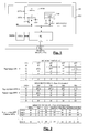
- the figure 1 represents an exemplary device comprising means for executing the method of writing and reading data according to the invention.
- the device takes the form of an integrated circuit IC on a semiconductor chip comprising a nonvolatile memory NVM, a volatile memory VM, a processing unit PU and an ICT communication interface.
- the memories NVM and VM are connected to the processing unit PU via a bus BS of data and address, and a control bus (not shown).
- the NVM memory is a byte-programmable memory and erasable per page, for example a FLASH memory comprising pages of 256 bytes.
- the processing unit PU for example a microprocessor or a microcontroller, is equipped with a PMEM program memory in which a VPG program for "virtualization" of the NVM memory, configured to execute the method of the invention, is recorded.
- the processing unit PU could be a wired logic sequencer (state machine or microprogrammed sequencer) configured to execute the method of the invention without intervention of a program stored in a program. program memory.
- the integrated circuit ICC is mounted on or encased in a portable medium HD ("Handheld Device"), for example a plastic card.
- the ICC circuit comprises contact or non-contact type ICT communication interface means, for example ISO contacts 7816 or an inductive coupling communication interface ISO 14443 or ISO 15693.
- the integrated circuit receives, via ICT interface means, WR (LBA, DT) commands for writing data into the NVM memory and RD (LBA) commands for reading data in the NVM memory.
- Each command comprises a code of the command and an LBA logical address of the data to be read or written.
- a write command further includes a DT data item to be written to the memory.
- the VPG virtualization program manages the contents of the NVM and executes the write and read commands so that, viewed from the outside, the NVM is perceived as a block-programmable virtual memory, in which a data block can be programmed indefinitely without worrying about its erasure.
- the LBA logical addresses supplied with the commands therefore form addresses designating blocks of the virtual memory. Such addresses are called “logical addresses” and the blocks they designate "logical blocks”.
- the program VPG in response to a data write command, the program VPG must only program the data in erased memory cells, and more precisely only program the memory cells to contain a bit equal to 0. This "write" reduced to memory cell programming is done without erasing previous data having the same logical address, which may possibly have already been programmed in the physical memory. These previous data are invalidated by the VPG program but are not erased.
- the VPG program later deletes the invalid data when performing memory maintenance tasks to obtain new erased memory cells ready to receive data.
- the VPG program may conduct maintenance tasks of grouping valid data that is scattered in the memory plane to expose invalid data groups which will then be erased to free up data. the memory space.
- programming data blocks in previously erased pages implies that each data is written in a block whose physical address is different from the logical address.
- the "block” type data must be "tagged” in a manner similar to page labeling in the methods described by EP 1 988 550 or US2005 / 0251643 .
- the label is for example the logical address of the data and is concatenated with the data.
- Such a labeling method applied to data blocks rather than to data pages results in a prohibitive multiplication of the number of labels and a complication of the labels (the address of a block being longer than the address of the data). 'a page). There then arises a problem of congestion of the memory space by labeling data.
- the invention proposes an advantageous solution making it possible to identify data in a memory space without resorting to the conventional labeling technique, by providing management data arranged in a dedicated memory space, and making it possible to manage the memory with reference to a virtual memory structure.
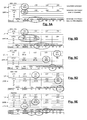
- the figure 2 schematically represents such a structure of the virtual memory, that is to say the memory as perceived from the outside through the VPG program.
- the figure 2 also represents the organization of the physical memory space inside the NVM memory.
- the virtual memory comprises K + 1 logical pages LP (LPO, LP1 ... LPK) designated by the logical addresses LPA (00, 01 ... K).
- the logical pages LP are here of the same size as the material pages of the memory zone A1 of the NVM memory, here 256 bytes, and are divided into individually addressable LB logic blocks designated by the LBA addresses present in the WR and RD commands. .
- the LBA address of a logic block is formed by the LPA address of the logical page in which the block is located and by the index of the block in the page, that is to say its rank in the page.
- the number of blocks per logical page is an initialization parameter of the VPG program, the choice of which is left to the discretion of the user. It will be assumed in the following and in the whole of the description, by way of non-limiting example, that the logical pages are divided into four logical blocks LB (LB1, LB2, LB3, LB4) of 64 bytes each.
- the physical memory space is divided into a memory area A1 intended to store application data received via the write commands WR, and a memory area A2 intended to receive the aforementioned management data. , designed to manage the data present in the first memory area.
- management data will be called "metadata" to distinguish it from application data. It is therefore data concerning the application data.
- the memory zone A1 comprises N + 1 physical pages of DPP data (DPP0, DPP1, ... DPPN) designated by physical addresses DPPA (00, 01, ... N).
- the physical pages are preferably of the same size as the logical pages and are therefore also of the same size as the hardware pages of the memory. They each comprise the same number of physical blocks as a logical page, ie four physical blocks PB (PB1, PB2, PB3, PB4) of 64 bytes each.
- the concept of "physical block” represents, for the virtualization program VPG, the smallest part of the physical memory that can be programmed in response to a write command of a logic block, and is independent of the hardware architecture of the NVM memory, here a programmable memory byte, for which smaller programmable data is therefore the byte.
- a "physical page” represents here, for the virtualization program VPG, the smallest erasable part of the physical memory plane, namely the hardware page of the NVM memory.
- the program VPG can for example use a subroutine "programming a block" including 64 iterations of a one-byte programming loop.
- the program VPG can use a subroutine "reading a block” including 64 iterations of a read loop of a byte.
- the processing unit PU is configured to read the NVM memory in words of 32 or 64 bits.
- the memory zone A2 comprises physical pages of MPP metadata designated by their physical address MPPA.
- the program VPG manages the memory zone A2 without notion of "block", and programs the metadata by exploiting the natural granularity offered by the memory, here a granularity of a byte in programming and reading, and a granularity of an erasing page.
- the program VPG implements the method of writing data with delayed erasure both in the memory zone A1 and in the memory zone A2.
- maintenance tasks are also provided in the memory area A2 to free memory space for the metadata, by deleting pages containing invalid metadata.
- the memory areas A1, A2 being in this embodiment two sectors of the NVM memory, the high and low limits of the memory areas A1, A2 may be defined by the program VPG, depending on parameters such as the size of the physical memory and the size of the logical blocks within the pages of the virtual memory.
- the VPG program determines an optimal allocation between the memory space allocated to the data and the memory space allocated to the metadata, and thus determines the limits of each memory area.
- the physical memory area A1 is necessarily larger than the virtual memory area because of the invalid data that the delayed erase write process generates.
- the program may be required to assign 896 pages to the zone A1, ie 224 KB of data, 128 pages to the A2 area, or 32 KB of metadata, and define a virtual memory of 218 KB representing 85.2% of the memory space offered by the physical memory.
- the memory zone A2 may be housed in a dedicated nonvolatile memory, distinct from the NVM memory.
- the memory zone A2 may comprise physical pages having a size different from the physical pages of the NVM memory.
- the method according to the invention does not impose a structural relationship between the physical pages of metadata and the physical pages of data and only requires that the metadata be accessible for reading and writing with sufficient granularity not to slow down. the execution of the program.
- this metadata structure comprises compact elements associated with the physical pages of the memory zone A1, called "descriptors" DSC0, DSC, ... DSCN.
- the descriptors provide the link between the logical pages and the physical pages as well as the link between the blocks physical and logical blocks. They also include valid or invalid status information of the data in the physical blocks.
- the physical address field DPPA receives the address DPPA of the physical page to which the descriptor is associated, preferably in the form of an index indicating the position of the physical page in the memory zone A1 relative to the first address of the zone. memory A1.
- the logical address field LPA receives the logical address LPA of a page of the virtual memory, preferably in the form of an index indicating the position of the logical page in the virtual memory.
- the WC field is reserved for a use described below but is also used to invalidate a descriptor.
- the invalidation value of the descriptor is obtained by programming all the bits of the WC field, ie "000000" in hexadecimal notation.
- DS fields are indexed fields describing the status of the data in the blocks of the physical page to which the descriptor is associated. More particularly, the rank of each DS field in the descriptor corresponds to the rank, in the physical page to which the descriptor is associated, of the physical block to which the DS field is associated.
- the DS (PB1) field is in the first position in the descriptor and is associated with the first block PB1 of the physical page to which the descriptor is associated.
- the DS (PB2) field is in second position in the descriptor and is associated with the second block PB2 of this physical page, etc., the number of DS fields in a descriptor being a function of the number of blocks per physical page.
- the size of a descriptor is in this case 15 bytes, and a physical page of 256 bytes of the memory area A2 can receive 16 descriptors, with 16 remaining bytes available to encode a page header in a way that will be described later.
- the NVM program configures the descriptors so that each physical page of the memory zone A1 is associated with a descriptor.
- the WC field described below, is also configured during the first use of the memory. AT At this stage, since no data has been written in the memory zone A1, the descriptors are not associated with any logical pages and the LPA field is left in the erased state. Likewise, the DS fields are left in the erased state.
- the figure 2 is a "photograph" at a given moment of the memory areas A1 and A2 and the virtual memory.
- the data and metadata shown as examples are hexadecimal and are reduced to one byte to simplify the drawing.
- a datum or a metadata may have values ranging from 00 (data or metadata with all the bits programmed) to FF (data or metadata completely erased), the intermediate values being composed of programmed bits (0). and erased bits (1).
- virtual memory Since virtual memory is "ideal" memory, it contains only valid data. There are DT1c, DT2 and DT3 data recorded respectively in the logic blocks LB1, LB4 and LB2 of the logical page LP1 of address 01. All the other logical blocks are equal to FF, which means that they have not not received data.
- the valid data DT1c, DT2 and DT3 are found in the memory zone A1.
- the data DT2 is stored in the block PB3 of the page DPP0 of address 00, and the data DT3 is stored in the block PB4 of this page.
- the data DT1c is stored in the block PB1 of the physical page DPP2 of address 02. Also found in the memory area A1 are invalid data DT1a, DT1b stored in the blocks PB1 and PB2 of the physical page DPP0.
- the link between the location of the data in the physical memory A1 and their location in the virtual memory is provided by the descriptors, using the fields described above.
- the descriptors also indicate the status of the data (valid or invalid).
- the memory zone A2 also includes the other descriptors DSC2 ... DSCN of the other physical pages whose DPPA field includes the address of the associated page and whose fields LPA, DS (PB1), DS (PB2), DS (PB3) , DS (PB4) are erased (equal to FF), which means that all other pages in memory area A2 do not contain data.
- the set of descriptors thus forms the equivalent of a compact database that allows each moment to know which logical block belongs to such data in such physical block, and to know if the data is valid or invalid.
- the figure 3 is a flowchart describing in a simplified way the execution of a programming operation of a data item in a logic block LBi (LPj) of a logical page LPj.
- the VPG program searches for a physical page DPPk linked to the logical page LPj by browsing the LPA fields of the descriptors.
- the VPG program searches for a deleted physical block PBi in the DPPk page by browsing the DS fields of the descriptor, until finding a field DS equal to FF, indicating that the block is deleted.
- the rank of the DS field in the descriptor allows the VPG program to deduce the index of the physical block in the DPPk page whose address is in the DPPA field, and thus allows it to reconstruct the address of the block, adding the index to the DPPA address.
- the program VPG programs the data DT in the physical block PB 1 of the page DPPk.
- the program VPG binds the physical block PBi of the page DPPk to the logical block LBi of the logical page LPj by programming, in the DS field of the descriptor relating to the block PBi, the index of the logic block LBi in the LPj page. In a 4-block virtual memory structure per page, this index corresponds to the two least significant bits of the address of the logic block LBi as supplied with the write command.
- step S02 the VPG program does not find a deleted DS field, which means that the physical page does not have an available block for writing the data.
- the program VPG returns to step S01 to search the descriptors for a new physical page linked to the logical page LPj.
- step S01 the VPG program does not find a DPPk physical page bound to logical page LPj.
- the program VPG goes to a step S05 where it chooses a descriptor associated with a valid physical page DPPk which is not linked to any logical page (LPA field deleted) and is therefore in the erased state.
- the VPG program links the physical page to the logical page LPj by programming the address of the logical page in the LPA field of its descriptor.
- step S06 the program VPG programs the data DT in the first physical block PB1 of the page DPPk.
- the program VPG binds the physical block PB1 to the logic block LBi by programming the index of the logical block in the first DS field of the descriptor.
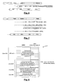
- FIGS. 4A, 4B, 4C, 4D and 4E describe in simplified manner the programming steps of the data DT1a, DT1b, DT1c, DT2, DT3 leading to the configuration of the physical memory represented on the figure 2 .
- the FIGS. 5A, 5B, 5C, 5D and 5E illustrate these steps and show how the configuration of the memory zones A1 and A2 evolves as the data is programmed, until the configuration of the figure 5E , which is identical to that of the figure 2 .
- the organization chart of the Figure 4A describes steps of executing a write command of a data DT1a in the logic block LB1 (LP1) (first logical block of the logical page LP1).
- the program VPG looks in the descriptors for a physical page linked to LP1 and can not find any (in this example, the memory is assumed to be completely empty).
- the program VPG chooses the erased physical page DPP0 and updates the descriptor DSC0 of this page by programming the value 01 in the field LPA in order to link it to the logical page LP1.
- the program VPG programs the data DT1a in the block PB1 (DPP0), Cf. Fig. 5A , and updates the descriptor DSC0 by programming in the field DS (PB1) the value 01 representing the index of the logic block LB1 (LP1)).
- the organization chart of the Figure 4B describes steps of execution of a write command of the data DT1b in the same logical block LB1 (LP1).
- the program VPG searches the descriptors for a physical page linked to the logical page LP1, finds the page DPP0 then searches in its descriptor for a deleted physical block and finds the field DS (PB2) erased.
- the program VPG programs the data DT1b in the physical block PB2 (DPP0), programs all the bits of the field DS (PB1) of the descriptor to invalidate the data DT1a present in the block PB1, and programs the value 01 in the DS (PB2) field, Cf.
- Fig. 5B which means that the valid data item DT1b of the logic block LB1 (LP1) is now in the physical block PB2 (DPP0).
- the organization chart of the figure 4C describes steps of executing a write command of the data item DT2 in the logic block LB4 (LP1).
- the VPG program looks in the descriptors for a physical page linked to the logical page LP1, finds the DPP0 page and then searches by means of the descriptors a physical block deleted in the page DPP0.
- the program VPG programs the data DT2 in the physical block PB3 (DPP0), then programs the value 04 in the DS field (PB3) of the descriptor, Cf. Fig. 5C .
- the organization chart of the figure 4D describes steps of executing a write command of the data item DT3 in the logic block LB2 (LP1).
- the VPG program looks in the descriptors for a physical page linked to the logical page LP1, finds the DPP0 page and then searches by means of the descriptors a physical block deleted in the page DPP0.
- the program VPG programs the data DT3 in the physical block PB4 (DPP0), then programs the value 024 in the DS field (PB4) of the descriptor, Cf. Fig. 5D .
- the organization chart of the figure 4E describes steps of executing a programming command of the data DT1c in the logic block LB1 (LP1).
- the program VPG searches in the descriptors a physical page linked to the logical page LP1, finds the DPP0 page then searches by means of descriptors a physical block erased in the page DPP0. Since the DPP0 page is entirely written, the program VPG looks for an erased page in step S21, chooses the physical page DPP2 and updates the descriptor DSC2 of this page by programming the value 01 in the field LPA in order to link it to the LP1 logical page.
- the program VPG programs the data DT1c in the physical block PB1 (DPP2), updates the descriptor DSC0 by programming all the bits of the field DS (PB2) of the descriptor DSC0 in order to invalidate the data DT1b present in the physical block PB2 (DPP0), and updates the descriptor DSC2 by programming the value 01 in the field DS (PB1).
- the data of a logical page can be stored in several physical pages and data written successively in the same logical block can remain in the physical memory.
- there can only be one valid data per logical block so that each programming of a data of a logical block necessarily entails the invalidation of the previously programmed data.
- Clearing a page involves assigning a new descriptor to the page and invalidating the descriptor associated with that page. Since the writing of metadata in the memory zone A2 is of the delayed erasure type, and therefore consists in a data programming, it is indeed not possible to delete the current descriptor of the page to return to "FF" the LPA and DS fields. Thus, the VPG program assigns a new descriptor to the page and invalidates the old descriptor by setting its WC field to 0.
- the compact structure descriptor chosen in this embodiment of the method of the invention requires that a physical page includes only data belonging to the same logical page.
- a "block descriptor" type descriptor structure could be provided and would make it possible to associate any block of block any logical page to any physical block of any physical page.
- Such a block descriptor structure would be large because each block descriptor should include the DPPA and LPA addresses of the physical and logical pages with which it is associated.
- the page descriptors including information on the content of the blocks of the page thus form an advantageous means in terms of compactness of the memory zone A2.
- metadata are also used to monitor the "cycling" of the pages (i.e., the number of erasure cycles they undergo). More particularly, a WC wear counter is assigned to each physical page of the memory area A1, and is stored in the memory area A2. The WC counter may be arranged in a dedicated wear descriptor in which the address of the page is shown. However, in the context of the implementation of the first aspect of the invention, where page descriptors are used, it is advantageous to place this WC counter in the descriptor structure, as shown in FIG. figure 2 .
- the WC counter is for example coded on 3 bytes, as indicated above.
- the VPG program initializes the WC counter of each physical page of data by programming a count value equal to 000001 (hexadecimal notation) at the time of the first configuration of the descriptors.
- the VPG program increments the counter after each deletion of the page.
- the WC meter thus accompanies the page throughout the lifetime of the memory.
- the WC counter of the descriptor DSC0 of the page DPP0 is equal to 000001, which means that the page has not yet been erased.
- WC counter of the descriptor DSC2 of the page DPP2 is equal to 000008, which means that the page has been erased 7 times.
- the cycling of the data pages can be controlled by the VPG program dynamically and / or statically, in order to homogenize the wear of the pages over the entire memory plane.
- Dynamic management of wear includes, for example, when writing data in erased physical pages, a step during which the program VPG selects erased pages having undergone the lowest number of erasure cycles.
- Static wear management includes, for example, a background task (background task) comprising steps of moving valid data of a page having undergone a low number of erasure cycles to a page having suffered more than one page. erase cycles, in order to free a weakly cycled page to use it more intensively thereafter.
- the deletion of a DPP data page is accompanied by the assignment of a new descriptor to the page, which implies the invalidation of the descriptor associated with this page, consisting of setting the WC field to 0.
- the WC counter of a descriptor intended to be invalidated is previously transferred into the new descriptor of the erased page.
- the flags SFG, FFG are provided in connection with an aspect of the invention described below.
- the identification field MID is encoded with a determined value, for example "3C", which indicates that the metadata page contains descriptors.
- the MID field is also used to invalidate the descriptors page, when it contains only invalid descriptors. In this case, the MID field is fully programmed and its value is "00" in hexadecimal notation.
- FF when the MID field is equal to "FF”, this means that the metadata page is available and can be used to record descriptors or any other metadata structure that will be described later.
- a descriptor page may only have invalid descriptors. These are all descriptors referring to pages containing invalid data.
- the VPG program can be configured to conduct a background task that aims to find the invalid descriptor pages, then erase them to free up memory space in the memory area A2.
- the WC counter of the descriptor page to be erased is previously set aside and reprogrammed in the header field of the descriptor page once it has been erased.
- a dynamic management of the wear of the metadata pages can also be provided, and includes for example, when writing metadata in deleted physical pages of the memory zone A2, a step during which the program VPG selects erased pages with the lowest number of erasure cycles.
- Static management of the wear of the metadata pages can also be provided and comprises, for example, a background task (background task) comprising steps for moving descriptors of a page having undergone a low number of cycles. erase to a page that has gone through more erase cycles.
- the management of tearing and voltage interruptions it causes typically requires the provision of specific data to monitor the programming process and erasure. When the memory is restarted, this data is read and makes it possible to detect a process interruption in order to put the memory back into its initial state and thus correct the effects of the power failure.
- the process tracking data in the prior art is concatenated with the application data and becomes significantly more complex when switching from page programming to block programming. It is thus necessary to concatenate with each block of application data not only labeling data but also process monitoring data.
- the labeling of the application data with process monitoring data is not an infallible method, there are still cases of uncertainty or memory cells receiving the process monitoring data are in an intermediate state between the programmed state and the erased state, and can be read as having a "1" or a "0" depending on external parameters such as temperature and voltage. circuit power, which can lead to a faulty diagnosis.
- the limitations of the known techniques lie in the fact that the process-monitoring data are concatenated with the application data and are therefore assigned a fixed memory location which does not make it possible to implement solutions intended to prevent diagnostic errors due to intermediate states.
- metadata of the memory area A2 are assigned to the process monitoring.
- the metadata assigned to process tracking is configured as a specific structure called a TINF "temporary information structure". on the figure 7 .
- These metadata structures are programmed in specific metadata pages called “temporary information pages” whose structure is also represented on the page. figure 7 .
- the identification field MID is encoded with a determined value, for example "F0", which indicates that the metadata page is a temporary information page.
- the MID field is also used to invalidate the temporary information page, when it contains only invalid temporary information structures. In this case, the MID field is fully programmed and its value is equal to "00" in hexadecimal notation.
- the DAD field receives the address of the descriptor of the physical page in which the data is programmed.
- This address includes the MPPA address of the metadata page in which the descriptor is located, expressed as a calculated index relative to the first page of the second memory area A2, and the descriptor index DIND in the metadata page.
- the DSIND field receives the index, in the descriptor, of the DS field concerned by the programming operation. Since 4 bits are sufficient to designate the four possible values of the index in a four-block virtual memory per logical page, the other four bits of the DSIND field can be used to store the value to be programmed in the DS field. As indicated above, this value is the index, in the logical page, of the logical block whose data must be programmed in the physical block.
- the SFG start flag is programmed in two steps, it is equivalent to two flags, namely a first start of process flag and a second start of process flag, allowing to frame the programming process of the TYPE, DAD and DSIND of the temporary information structure.
- the DPPA field already described above receives the address of the physical page of data to be erased, in the form of an index.
- the ODAD field contains the address of the old descriptor, which is the descriptor of the page before it is deleted. Indeed, as indicated above, the deletion of a page is necessarily accompanied by the programming of a new descriptor.
- the MPPA field already described above receives the address of the metadata page to be erased, in the form of an index.
- the WC field receives the WC wear counter value from the metadata page to be erased.
- the program VPG copies the value of the WC counter into the WC field in the header of the erased page, and then programs the end flag FFG.
- the rearrangement of descriptors is a background task that can be performed by the VPG program to group valid descriptors into the same descriptor page. It implies the invalidation of the initial descriptors.
- This task makes it possible to display pages of descriptors containing only invalid descriptors, which can then be erased, and to increase the concentration of valid descriptors in the valid pages of descriptors.
- This task can also be performed as part of static management of metadata page wear, to transfer descriptors into pages that have undergone more erasure cycles, having a higher value WC counter.
- the VPG program moves the valid descriptors to the other page, and then invalidates the start page by programming all the bits of the MID field of the page, as described above.
- the page will be erased by another background task, or "garbage collection” task, to erase invalid pages.
- the program VPG programs the end flag FFG of the temporary information structure.
- this tracking is also ensured by means of the byte redundancy in the DS fields of the descriptors, described above.
- the redundant byte is programmed after programming the first byte of the field. If a power failure occurs during the programming of this field, the difference between the first and second bytes can detect the interruption of the programming process.
- the SFG start flags and the FFG end flags in the metadata page headers also allow the VPG program to detect that a power failure has occurred during header programming, the end flag of the header being last programmed.
- the VPG program executes an "anti-tearing" algorithm (ie which aims to counter the effects of a power failure) and analyzes the SFG, FFG flags present in the structures of temporary information, in the headers of the descriptor pages and in the headers of the temporary information pages, to detect a possible anomaly. It also looks for byte redundancy anomalies in the descriptors if an inconsistency has been detected in the flags. A diagnosis is then established, to define, if necessary, the actions to be conducted in order to restore the memory in its initial state, that is to say the configuration in which it was before the triggering of the operation (programming or erasure ) interrupted by the power failure.
- an "anti-tearing" algorithm ie which aims to counter the effects of a power failure
- An anomaly is, for example, observed when two flags of the same structure (temporary information or header) do not have the same value, which means that a process has been interrupted.
- the TYPE field of temporary information structures makes it possible to know which process is involved.
- the program VPG copies this structure in a temporary information page of the memory area A2 to stabilize it, before proceeding to an analysis of the data to establish a diagnosis. and before defining possible remedial actions.
- the temporary information structure in default has been copied, the initial temporary information structure is neutralized by programming its erased bits (changing from 1 to 0) and overprogramming of its programmed bits.
- an FFG end flag may be in an intermediate state if a power failure occurred while the VPG program was programming it. Such a flag can be read equal to "1" at power up, which is considered an anomaly since the start flag is programmed and is therefore equal to 0. However, this same end flag can then be read equal to 0 at the next power up, if a new power failure occurs after restarting the memory, before the VPG program has had time to establish a diagnosis. This change in the value read from the flag may depend on external parameters such as the temperature or the supply voltage of the circuit.
- Descriptors with an anomaly can also be copied. If a descriptor has a defect in the byte redundancy (bytes not having the same value), the descriptor is copied to stabilize it and the initial descriptor is invalidated. However, this operation is carried out only if, at the moment of the power failure, the defective descriptor was being programmed in relation with an operation of programming a datum in a physical block (the nature of the operation is determined by the "TYPE" field of the temporary information structure, which must therefore be DPI type information).
- header fields with an anomaly are not copied and are simply overprogrammed because they do not pose the same problem of instability and validity: when they are overprogrammed, the algorithm is in a stable state and at the next power up, they will necessarily be reprogrammed with the same value.
- the correspondence table includes a list of labels and, in relation to each label, a physical address of the data item carrying this label.
- the increase in the number of labels also leads to a proportional complication of the correspondence table structure and the size of the volatile memory. .
- a compact size correspondence table may therefore be desired.
- the VPG program uses a compact Look-Up Table (LUT) to access the NVM.
- the correspondence table is stored in the volatile memory VM of the integrated circuit (Cf. Fig. 1 ) and is reconstructed by the program VPG at each start of the integrated circuit, from a reading of the metadata.
- the correspondence table LUT does not point to the memory zone A1 where the data are located, but points to the memory zone A2 where the metadata are located.
- the lookup table provides DAD descriptor addresses. These addresses include an MPPA address of a descriptor page and the DIND index of a descriptor in this page.
- the lookup table is also used by the VPG program to manage and update a list of invalid pages to be erased, as well as to manage and update a list of erased pages.
- the figure 8 schematically represents an example structure of the correspondence table LUT.
- the lookup table has four distinct areas, an IDX area, an EXT area, a FRE area, and an INV area.
- the IDX field contains descriptor addresses indexed on LPA logical addresses. At each address LPA i corresponds the address of a valid descriptor including this address in its LPA field.
- the EXT field also contains descriptor addresses, but these addresses are not indexed to the LPA logical addresses and are only ranked in ascending order of the logical addresses that appear in the LPA field of the descriptors.
- the FRE zone contains descriptor addresses associated with erased pages of the memory zone A1, ie descriptors whose fields DPA and DS are in the erased state (the fields DPPA and WC being however informed as soon as the descriptors have been formed, as described above).
- the addresses of the descriptors are listed in ascending order (or, optionally, in decreasing order) of the values of the WC counters they include. In other words, the first descriptor address which is at the top of the FRE zone (or at the bottom, if decreasing ranking) is that of the deleted descriptor having the lowest WC counter value and therefore having the smallest number of erase cycles.
- the INV field contains addresses of all the invalid data pages present in the memory area A1. This area is used by the VPG program to perform a background task to free memory space by deleting invalid pages.
- the VPG program constructs the LUT correspondence table each time the integrated circuit is powered up. For this purpose, it scans all the descriptor pages and searches, for each logical address LPA i valid descriptors whose LPA field includes this address LPA i . The first descriptor found is placed in the IDX area and is associated with the logical address LPA i . The other descriptors found meeting this definition are placed in the EXT field and are ranked in ascending order of the LPA addresses they contain.
- the correspondence table comprises in its zone IDX and in its zone EXT all the addresses of the valid descriptors associated with physical pages which comprise at least one valid datum of the memory Virtual.
- the EXT zone is constructed simultaneously with this scan, by storing therein the descriptor addresses whose LPA field has been found in the erased state, and classifying them by increasing (or decreasing) values of the WC counters they comprise. In the same way the INV area can be built simultaneously, by registering the addresses of the descriptors whose four DS fields are found equal to 0.
- the physical address of the logical block must first be determined to execute the command.
- the program VPG extracts from the address of the logical block the address LPA i of the logical page in which the logical block is located and searches in the zone IDX, by means of this address LPA i , the address a descriptor. This step will now be described.
- the VPG program Since this zone is not indexed, the VPG program must itself find the descriptor (s) that include the LPA address i . Since the descriptors are classified by increasing order of the LPA logical addresses with which they are associated, the program VPG uses a method of convergent research by successive approaches which may need to read some descriptors not having the correct address LPA i but which allows it quickly to converge to the descriptor comprising this address, if one exists.
- the program VPG When the descriptor is found, the program VPG, if it is executing a write command, proceeds as it did with the first descriptor found via the IDX field, and so on until finding the descriptor including the LPA address i and a deleted DS field. If all DS fields are busy or invalid, the VPG program goes to the FRE zone to select an erased page descriptor.
- the VPG program proceeds as it did with the first descriptor found through the IDX field, and so on until it finds the descriptor including the address LPA i and a DS field with the index of the logic block to be read. If none of the DS fields has this index, it means that no data has been programmed into this logical block. The program VPG then responds to the command by returning the value "FF" meaning that the logical block is blank or sends an appropriate response.
- the received command is a write command
- the program VPG must also look for a descriptor associated with the target address LPA i and which comprises a field DS containing the same logical block index as the target logic block, and memorize the address of the descriptor as well as the index of the DS field.
- the program VPG does not stop at the desired descriptor to write the data, but must scan all the descriptors including the address LPA i to ensure that there is not in the memory area A1 a given previously programmed with the same logical address.
- the figure 9 is an overview of the tasks that can be conducted by the VPG program, in one embodiment implementing the four aspects of the invention. After powering up the integrated circuit, initialization tasks are first performed. Then the VPG program performs dynamic tasks and slave tasks.
- Dynamic tasks are for example the execution of read or write commands, or any other external command that may be provided, for example the execution of a command to invalidate a logical page.
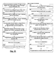
- FIG. 11 represents a flowchart that summarizes the main steps of the execution of the order with implementation of all aspects of the invention.
- FIG. 11 represents a flowchart that summarizes the main steps of the execution of the command with implementation of all aspects of the invention.
- the static page wear management task is to transfer data or metadata to erased data or metadata pages that have a higher value WC counter.
- the so-called "slave” tasks are those that are performed simultaneously with dynamic or background tasks. These include the programming of temporary information structures for the implementation of the anti-tear algorithm, and the updating of the LUT correspondence table.
- the programming of the temporary information structures is carried out in relation to any task or command execution for which a temporary information structure is provided, that is to say the programming of a physical block of data (data structure).
- temporary information DPI the deletion of a physical data page (temporary information structure DEI), the deletion of a metadata page (temporary information structure MEI) and the rearrangement of descriptors (structure of data).
- temporary information DPRI the rearrangement of descriptors
- the dynamic management of wear has been described above in connection with the description of the WC counter and can be facilitated by the use of the table of correspondence LUT (FRE zone of the table) with regard to the data pages.
- the VPG program performs this task on the fly when choosing an erased metadata page, reading WC counters in the header fields of these pages, and selecting the page with the lowest value WC counter.
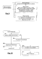
- the organization chart of the figure 10 describes examples of post-power initialization tasks:
- the program VPG determines whether the memory is used for the first time, for example by determining whether the memory zone A2 comprises metadata.
- the program VPG constructs the correspondence table LUT from a reading of the metadata.
- the organization chart of the figure 11 describes the execution of a write command of a data item DT in an ILBi target logical block LBi of an LPA address target logical page.
- the program VPG assembles the fields MPPA and DIND to obtain the address DAD of the descriptor.
- the program VPG performs a first reading of the descriptor to find the DPPA address of the target physical page linked to the target logical page.
- the program VPG carries out a second reading of the descriptor to find the index DSIND first deleted field DS (FF) and derives the index of the physical block PBj erased used for programming the data.
- the program VPG assembles the address DPPA and the index of the physical block to obtain the address of the physical block PBj.
- the program VPG creates a temporary information structure TINF of the type DPI, and programs the following fields: a part of the flag SFG, the field TYPE, the field DAD (address of the descriptor), the DSIND index of the DS field and the value of the DS field, then the rest of the SFG flag.
- the program VPG programs data in the physical block PBj.
- the program VPG updates the descriptor by programming in the deleted DS field the ILB index i of the target logic block LBi.
- the program VPG programs the final flag FFG in the temporary information structure DPI.
- step S33 the program VPG goes to a step S40 instead of going to step S34, if it does not find a deleted field DS in the descriptor.
- the program VPG searches in the EXT zone of the correspondence table LUT the address of another descriptor
- step S41 it reads the address field LPA present in the descriptor.
- step S42 the program VPG checks whether the content of the LPA is equal to the address LPAi of the target logical page. If the answer is positive, the VPG program returns to step S32 to analyze the descriptor. If the answer is negative, the VPG program goes to step S43.
- step S43 the program VPG determines whether the correspondence table LUT may contain another descriptor address associated with the target logical page. The answer is negative if the successive approaches research described above has already allowed us to examine all LPAi address descriptors close to LPAi (ie LPA i-1 and LPA i + 1 ) and that descriptor address between the addresses of descriptors already analyzed. In this case, the VPG program goes to a step S44. If the search is not completed, the VPG program returns to step S40.
- the program VPG chooses a new physical page erased while applying the algorithm of dynamic management of the pages wear by means of the counter WC, looking for a descriptor having a counter WC of low value and LPA fields cleared.
- the address of the deleted physical page is read in the DPPA field of the descriptor.
- the VPG program configures the descriptor of the selected page by programming the LPA field of the descriptor.
- the program VPG creates a temporary information structure TINF of the type DPI, and programs the following fields: a part of the flag SFG, the field TYPE, the field of address DAD of the descriptor, the DSIND index of the DS field and the value of the DS field, then the rest of the SFG flag.
- the program VPG programs the data in the first physical block of the chosen physical page.
- step S48 it updates the descriptor by programming in the first DS field of the descriptor the ILB index i of the target logic block LBi.
- the program VPG updates the correspondence table LUT.
- step S46B it programs the final flag FFG in the temporary information structure DPI.
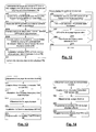
- the organization chart of the figure 12 describes the execution of a read command of a data DT in a target logical block LBi ILB index i of a target logical address LPA i .
- the program VPG reads the IDX area of the LUT using the address LPA i as index, to find the address MPPA of the descriptor page linked to the target logical page and the index DIND descriptor in the descriptor page.
- step S51 the VPG program assembles the MPPA address and the DIND index to obtain the DAD address of the descriptor.
- the program VPG performs a first reading of the descriptor to find the DPPA address of the target physical page linked to the target logical page.
- step S52B it carries out a second reading of the descriptor to find the DSIND index of the DS field containing the ILB index i of the target logic block LBi, and deduces therefrom the index of the target physical block PBj where it is located. the data to read. If no DS field is found with this index, the program VPG goes to step S55, otherwise it goes to step S53.
- the program VPG assembles the address DPPA and the index of the physical block to obtain the address of the physical block PBj.
- the program VPG reads the data in the physical block PBj and provides it to the issuer of the command.
- step S55 the VPG program searches the EXT field of the LUT correspondence table for the address of another descriptor.
- step S56 it reads the address LPA present in the descriptor.
- step S57 the program VPG checks whether the LPA field contains the address LPA i of the target logical page. If the answer is positive, it goes to step 52A to analyze the descriptor, otherwise it goes to step S58.
- step S58 the program VPG determines whether the correspondence table LUT may contain another descriptor address associated with the target logical page. The answer is negative if the successive approach search described above has already allowed to examine all LPA address descriptors. In this case, the VPG program goes to a step S59. If the search is not completed, the VPG program returns to step S55.
- the organization chart of the figure 13 describes an operation of erasing a page of invalid data.
- the program VPG creates a temporary information structure TINF type DEI and programs the following fields: a part of the flag SFG, the field TYPE, the field of address DPPA of the physical page to be erased , the ODAD field containing the address of the descriptor of the physical page to be erased, then the rest of the SFG flag.
- step S72 it erases the physical page.
- step S73 it invalidates the old descriptor by putting its WC field to 0.
- the program VPG programs the final flag FFG in the temporary information structure DEI.
- the organization chart of the figure 14 describes an erase operation of an invalid metadata page.
- the program VPG creates a temporary information structure TINF type MEI and programs the following fields: a part of the flag SFG, the field TYPE, the address MPPA of the physical page to be erased, the WC field, the WC counter value of the page (header), then the rest of the SFG flag.
- the program VPG erases the physical page.
- the program VPG programs the WC counter of the physical page erased from the value stored in the temporary information structure.
- the program VPG programs the final flag FFG in the temporary information structure MEI.
- the organization chart of the figure 15 describes a reordering operation of valid descriptors of a metadata page.
- the program VPG creates a temporary information structure TINF type DEI and programs the following fields: a part of the flag SFG, the field TYPE, the field of address MPPA of the physical page containing the valid descriptors to move, then the rest of the SFG flag.
- step S92 the VPG program invalidates the metadata page by setting the SFG flag to 0, then setting the MID field to 0, and finally setting the FFG flag to 0.
- the program VPG programs the final flag FFG in the temporary information structure DEI.
- the program VPG updates the correspondence table LUT.
- the organization chart of the figure 16 describes a valid data defragmentation operation.
- the VPG program looks for a fragmented logical page, searching by means of the descriptors the physical pages linked to this page and containing valid data.
- a logical page is fragmented if the data it contains is scattered across multiple physical pages.
- the program VPG During a step S101, the program VPG generates internal commands for writing, in a new erased page, data of the logical page which are present in dispersed physical blocks. Then it invalidates the starting physical blocks.
- the operation includes dynamic wear management (selecting an erased page having the lowest WC counter) and is secured using the temporary information structures.
- the descriptors of the new page are updated, as well as the descriptors of the initial pages.
- the LUT mapping table is also updated.
- the present invention is also susceptible of various applications. Although initially designed to optimize the use of FLASH memories, the method according to the invention can be applied to any type of memory in which data must be erased before being programmed, for example EEPROM memories.
- the aspect of the invention relating to the use of descriptor type metadata is advantageously applied to a FLASH memory by ensuring that a "physical page" and a "logical page” in the sense of the method correspond to an erasable hardware page of the FLASH memory.
- a "physical page” in the sense of the method of the invention may not correspond to the smallest erasable part of the memory used.
- a physical page in the sense of the method could include two-and-a-half pages and thus correspond to a hardware page of the memory.
- a "physical page" in the sense of the method could include M erasable blocks and could correspond or not correspond to a hardware page of the memory, depending on whether M and N are equal or no.
Abstract
Description
La présente invention concerne les mémoires non volatiles et notamment les mémoires effaçables et programmables électriquement de type FLASH.The present invention relates to non-volatile memories and in particular electrically erasable and programmable memories of FLASH type.
Le marché des mémoires effaçables et programmables électriquement sur microplaquettes de semi-conducteur est traditionnellement partagé entre la famille des mémoires EEPROM et celle des mémoires FLASH (ou FLASH-EEPROM).The market of erasable and electrically programmable memories on semiconductor chips is traditionally shared between the family of EEPROM memories and that of FLASH memories (or FLASH-EEPROM).
Les mémoires EEPROM comprennent des cellules mémoire comportant un transistor à grille flottante et un transistor d'accès. Les mémoires de type FLASH ne comportent qu'un transistor à grille flottante par cellule mémoire, et présentent l'avantage d'une grande compacité en termes de surface de semi-conducteur occupée (nombre de cellules mémoire par unité de surface). En contrepartie, l'absence de transistor d'accès nécessite de prévoir des tensions de seuil positives tant pour les cellules mémoire effacées que les cellules mémoire programmées, afin de ne pas créer des courts-circuits sur les lignes de bit. Les oxydes de grille doivent ainsi être épais pour maintenir durablement les charges électriques piégées dans les grilles flottantes, ce qui entraîne une augmentation du temps d'effacement. L'effacement des cellules mémoire FLASH est souvent effectué par effet tunnel tandis que leur programmation est effectuée par injection d'électrons chauds. Le temps nécessaire à la programmation des cellules mémoire est court, par exemple 5 microsecondes, tandis que le temps d'effacement est long, par exemple 100 millisecondes. Par ailleurs, la programmation par injection d'électrons chauds entraîne l'apparition d'un fort courant de programmation, de sorte que le nombre de cellules mémoire pouvant être programmées simultanément est généralement limité à un octet.The EEPROM memories comprise memory cells comprising a floating gate transistor and an access transistor. The FLASH type memories comprise only one floating gate transistor per memory cell, and have the advantage of a great compactness in terms of occupied semiconductor surface (number of memory cells per unit area). In return, the absence of an access transistor requires the provision of positive threshold voltages for both the erased memory cells and the programmed memory cells, so as not to create short circuits on the bit lines. The gate oxides must thus be thick in order to sustainably maintain the electrical charges trapped in the floating gates, which leads to an increase in the erase time. The erasure of the FLASH memory cells is often done by tunneling while their programming is performed by injection of hot electrons. The time required for programming the memory cells is short, for example 5 microseconds, while the erase time is long, for example 100 milliseconds. Furthermore, the hot electron injection programming results in the appearance of a strong programming current, so that the number of memory cells that can be programmed simultaneously is generally limited to one byte.
Les mémoires FLASH ont ainsi été, originellement, dédiées au stockage de masse. Divers perfectionnements furent ensuite proposés afin qu'elles puissent offrir des caractéristiques se rapprochant des mémoires EEPROM. Parmi les perfectionnements on peut citer la conception d'une mémoire FLASH effaçable par page, telle que décrite par le brevet
Ces perfectionnements ont permis de commercialiser des mémoires FLASH effaçables par page offrant les mêmes fonctionnalités apparentes que certaines mémoires EEPROM, mais dans lesquelles des limitations subsistaient :
- un temps d'effacement long, ce qui peut s'avérer gênant dans certaines applications. En effet, le temps apparent d'écriture d'un octet est essentiellement imposé par le temps d'effacement de la page qui reçoit l'octet, laquelle doit être entièrement effacée chaque fois qu'un nouvel octet y est programmé, les autres octets initialement présents dans la page devant également y être écrits ;
- une absence de protection contre les coupures intempestives de tension d'alimentation pendant l'effacement d'une page ou la programmation de blocs.
- a long erasure time, which can be inconvenient in some applications. Indeed, the apparent time of writing a byte is essentially imposed by the erasure time of the page that receives the byte, which must be completely erased each time a new byte is programmed, the other bytes initially present in the page to be written there;
- lack of protection against unintentional power supply interruptions during page deletion or block programming.
De ce fait les mémoires FLASH ne pouvaient pas, initialement, être utilisées comme mémoires enchâssées ("Embedded memories") dans des circuits intégrés destinés à des applications où le risque de coupure d'alimentation électrique est élevé. Il s'agit généralement d'applications aux cartes à puce ou aux étiquettes électroniques, dans lesquelles l'alimentation des circuits intégrés peut disparaître en cas "d'arrachement" (retrait de la carte du lecteur de carte).As a result, FLASH memories could not initially be used as Embedded Memories in integrated circuits for applications where the risk of power failure is high. These are usually applications for smart cards or electronic tags, in which the power of the integrated circuits can disappear in case of "tearing" (removal of the card from the card reader).
D'autres perfectionnements aux mémoires de type FLASH ont donc visé l'optimisation du temps d'écriture des données et la protection des données contre l'arrachement. A cet effet, on a proposé des procédés d'écriture de données dits "à effacement différé". Selon ces procédés, l'écriture de données ne s'effectue que dans des pages effacées et consiste dans des cycles de programmation de cellules mémoire sans cycle d'effacement associé. La programmation successive de données dans des pages effacées fait apparaître des données invalides, d'où un remplissage d'espace mémoire supérieur à l'espace mémoire nécessaire pour stocker les données valides. Lorsque l'espace mémoire se réduit, les données invalides sont effacées pour libérer de l'espace mémoire (effacement différé). On a généralement proposé d'utiliser les procédés d'écriture à effacement différé en relation avec la protection des données contre l'arrachement ("tearing proof programming" ou "anti-tearing methods"), car les applications nécessitant une écriture rapide de données sont généralement des applications sensibles aux problèmes d'alimentation électrique (cartes à puce).Further improvements to FLASH memories have therefore aimed at optimizing the data writing time and protecting the data against tearing. For this purpose, so-called "delayed erasure" data writing methods have been proposed. According to these methods, the writing of data takes place only in erased pages and consists of programming cycles of memory cells without associated erase cycle. Programming successive data in erased pages causes invalid data to appear, resulting in more memory space being filled than the memory space needed to store the valid data. When memory space is reduced, invalid data is cleared to free memory space (Delayed Deletion). It has generally been proposed to use delayed-erase write methods in connection with data tearing proofing ("tearing proof" or "anti-tearing methods"), since applications require fast writing of data. are generally sensitive applications to power supply problems (smart cards).
A titre d'exemple, la demande de brevet
La demande de brevet
Également, les documents
Also, documents
En résumé, les procédés antérieurs à effacement différé manipulent des pages entières. Comme les pages de données sont écrites dans des pages matérielles pré-effacées dont l'adresse est arbitraire, on doit associer à chaque page de données une adresse logique de page ou "étiquette" qui permet de trouver la page. Cette "étiquette" est enregistrée avec les données de la page et est "attachée" à celles-ci, c'est-à-dire concaténée et placée dans la même page physique. Une autre caractéristique des procédés antérieurs est que chaque programmation d'une donnée en réponse à une commande d'écriture nécessite la lecture de toutes les données de la page, l'insertion de la nouvelle donnée dans les données de la page, puis la reprogrammation de toutes les données de la page mise à jour. Il s'ensuit une "consommation" importante de pages effacées, en d'autres termes un "cyclage" élevé et par conséquent une accélération de l'usure des cellules mémoire (le "cyclage" représentant le nombre de fois qu'une page a été effacée).In summary, the prior methods of delayed erasure manipulate whole pages. Since the data pages are written in pre-erased hardware pages whose address is arbitrary, each page of data must be associated with a logical page address or "tag" that makes it possible to find the page. This "tag" is registered with the data of the page and is "attached" thereto, that is, concatenated and placed in the same physical page. Another feature of the prior methods is that each programming of a data in response to a write command requires reading all the data of the page, inserting the new data into the data of the page, and then reprogramming all data on the updated page. This results in a significant "consumption" of erased pages, in other words a high "cycling" and consequently an acceleration memory cell wear ("cycling" is the number of times a page has been erased).
La présente invention propose des perfectionnements aux procédés d'écriture à effacement différé.The present invention provides improvements to the delayed erase write methods.
Plus particulièrement, des modes de réalisation de l'invention concernent un procédé pour écrire et lire des données dans des cellules mémoire non volatiles effaçables et programmables électriquement, comprenant les étapes consistant à : définir dans une première zone mémoire non volatile des pages de données effaçables comprenant des blocs de données programmables, et définir dans une seconde zone mémoire non volatile des pages de métadonnées effaçables comprenant des structures de métadonnées associées aux pages de données et comprenant, pour chaque page de données, un compteur d'usure contenant une valeur représentative du nombre de fois que la page a été effacée. Le procédé comprend également les étapes consistant à attribuer à chaque page de métadonnées un compteur d'usure contenant une valeur représentative du nombre de fois que la page de métadonnées a été effacée, agencer le compteur d'usure d'une page de métadonnées à l'intérieur de la page de métadonnées, avant d'effacer une page de métadonnées, programmer dans la seconde zone mémoire une structure d'information temporaire comprenant une adresse dans la seconde zone mémoire de la page de métadonnées à effacer, le compteur d'usure de la page de métadonnées, et, après avoir effacé la page de métadonnées, lire le compteur d'usure dans la structure d'information temporaire, incrémenter le compteur d'usure et le programmer dans la page de métadonnées effacée.More particularly, embodiments of the invention relate to a method for writing and reading data in erasable and electrically programmable nonvolatile memory cells, comprising the steps of: defining in a first nonvolatile memory area erasable data pages; comprising programmable data blocks, and defining in a second non-volatile memory area erasable metadata pages comprising metadata structures associated with the data pages and comprising, for each data page, a wear counter containing a value representative of number of times the page has been cleared. The method also includes assigning to each metadata page a wear counter containing a value representative of the number of times the metadata page has been erased, arranging the wear counter of a metadata page to the metadata page. inside the metadata page, before erasing a metadata page, programming in the second memory zone a temporary information structure comprising an address in the second memory zone of the metadata page to be erased, the wear counter From the metadata page, and after clearing the metadata page, read the wear counter in the temporary information structure, increment the wear counter, and program it into the deleted metadata page.
Selon un mode de réalisation, le procédé comprend également des étapes consistant à, avant de programmer l'adresse de la page de métadonnées à effacer, programmer dans la structure d'information temporaire un drapeau de début d'effacement, et après avoir programmé le compteur d'usure incrémenté dans la page de métadonnées effacée, programmer un drapeau de fin d'effacement dans la structure d'information temporaire.According to one embodiment, the method also comprises the steps of, before programming the address of the metadata page to be deleted, programming in the temporary information structure an erase start flag, and after programming the wear counter incremented in the deleted metadata page, program an erase end flag in the temporary information structure.
Selon un mode de réalisation, le procédé comprend les étapes consistant à programmer, dans chaque structure de métadonnée associée à une page de données, une information sur le statut, valide ou invalide, de la page, et effacer des pages de données invalides.According to one embodiment, the method comprises the steps of programming, in each metadata structure associated with a data page, information on the status, valid or invalid, of the page, and erasing invalid data pages.
Selon un mode de réalisation, le procédé comprend les étapes consistant à invalider une structure de métadonnées associée à une page de données effacée, attribuer une nouvelle structure de métadonnées à la page de données effacée, et programmer dans la nouvelle structure de métadonnées une valeur incrémentée du compteur d'usure présent dans l'ancienne structure de métadonnées.According to one embodiment, the method comprises the steps of invalidating a metadata structure associated with an erased data page, assigning a new metadata structure to the erased data page, and programming an incremented value in the new metadata structure. the wear counter present in the old metadata structure.
Selon un mode de réalisation, le procédé comprend les étapes consistant à invalider les structures de métadonnées associées à des pages de données effacées, et effacer une page de métadonnées ne comprenant que des structures de métadonnées invalides.According to one embodiment, the method comprises the steps of invalidating the metadata structures associated with erased data pages, and erasing a metadata page comprising only invalid metadata structures.
Selon un mode de réalisation, le procédé comprend les étapes consistant à invalider une page de métadonnées ne comprenant que des structures de métadonnées invalides, et effacer une page de métadonnées lorsqu'elle est invalide.According to one embodiment, the method comprises the steps of invalidating a metadata page comprising only invalid metadata structures, and deleting a metadata page when it is invalid.
Selon un mode de réalisation, le procédé comprend des étapes de gestion dynamique de l'usure des pages consistant à : lorsqu'une donnée ayant une doit être programmée dans une nouvelle page de la première zone mémoire, sélectionner, parmi plusieurs pages effacées de la première zone mémoire, la page ayant le compteur d'usure le moins élevé, et écrire la donnée dans la page sélectionnée.According to one embodiment, the method comprises steps of dynamic management of the page wear consisting of: when a data item having one must be programmed in a new page of the first memory area, selecting from among several deleted pages of the first memory area, the page having the lowest wear counter, and write the data in the selected page.
Selon un mode de réalisation, le procédé comprend des étapes de gestion dynamique de l'usure des pages consistant à : dresser une liste d'adresses de pages de données effacées de la première zone mémoire, classer les adresses de pages effacées par ordre croissant ou décroissant des valeurs des compteurs d'usure qu'elles comportent, et lorsqu'une donnée doit être programmée dans une nouvelle page de la première zone mémoire, sélectionner parmi la liste des adresses de pages, celles qui se rapporte à une page métadonnées comprenant un compteur d'usure ayant la plus faible valeur ou l'une des plus faibles valeurs, et programmer la donnée dans la page sélectionnée.According to one embodiment, the method includes steps of dynamically managing page wear consisting of: compiling a list of erased data page addresses of the first memory area, sorting the erased page addresses in ascending order or decreasing values of the wear counters they comprise, and when data must be programmed in a new page of the first memory zone, select from the list of page addresses, those which relates to a metadata page comprising a wear counter having the lowest value or one of the lowest values, and programming the data in the selected page.
Selon un mode de réalisation, le procédé comprend une étape de gestion statique de l'usure des pages consistant à transférer dans une seconde page de données de la première zone mémoire des données présentes dans une première page de données, la seconde page ayant un compteur d'usure présentant une valeur plus faible que le compteur d'usure de la première page.According to one embodiment, the method comprises a static page wear management step of transferring data present in a first data page to a second page of data of the first memory area, the second page having a counter wear value with a lower value than the wear meter on the first page.
Selon un mode de réalisation, le procédé comprend une étape consistant à configurer les structures de métadonnées associées aux pages de données sous forme de descripteurs, un descripteur étant associé à une page de données et comprenant : un champ de métadonnées formant le compteur d'usure, un premier champ contenant l'adresse de la page dans la première zone mémoire ou un index indiquant la position de la page dans la première zone mémoire, un second champ contenant l'adresse d'une page logique dans une mémoire virtuelle ou un index indiquant la position d'une page logique dans une mémoire virtuelle, et, pour chaque bloc de données de la page de données à laquelle le descripteur est associé, un troisième champ contenant une information sur l'emplacement du bloc de données dans la page de données, une information sur le statut du bloc parmi au moins les trois statuts suivants : bloc effacé, bloc contenant une donnée valide ou bloc contenant un donnée invalide, et une information sur la position dans la page logique de la donnée enregistrée dans le bloc considéré.According to one embodiment, the method comprises a step of configuring the metadata structures associated with the data pages as descriptors, a descriptor being associated with a data page and comprising: a metadata field forming the wear counter , a first field containing the address of the page in the first memory area or an index indicating the position of the page in the first memory area, a second field containing the address of a logical page in a virtual memory or an index indicating the position of a logical page in a virtual memory, and for each block of data of the data page to which the descriptor is associated, a third field containing information on the location of the data block in the page of data, information on the status of the block among at least the following three statuses: block deleted, block containing a valid datum or block containing an inv data alide, and information on the position in the logical page of the data recorded in the block considered.
Selon un mode de réalisation, le troisième champ est un champ de métadonnées indexé dont la position dans le descripteur désigne un bloc de données de la page de données à laquelle le descripteur est associé, et dont le contenu peut présenter une valeur effacée indiquant que le bloc désigné est effacé, une valeur programmée indiquant que le bloc désigné contient une donnée invalide, ou une valeur partiellement programmée donnant une information sur l'emplacement dans la page logique de la donnée enregistrée dans le bloc désigné.According to one embodiment, the third field is an indexed metadata field whose position in the descriptor denotes a block of data of the data page to which the descriptor is associated, and whose content may have an erased value indicating that the designated block is cleared, a programmed value indicating that the designated block contains invalid data, or a partially programmed value giving information about the location in the logical page of the data recorded in the designated block.
Selon un mode de réalisation, le procédé comprend une étape consistant à définir les première et seconde zones mémoire au sein d'un même mémoire non volatile.According to one embodiment, the method comprises a step of defining the first and second memory areas within the same non-volatile memory.
Selon un mode de réalisation, le procédé comprend, en réponse à une commande de lecture d'une donnée comportant une adresse logique, les étapes consistant à trouver dans la seconde zone mémoire une structure de métadonnées contenant cette adresse logique et associée à des données valides, lire dans la structure de métadonnées l'adresse de la donnée dans la première zone mémoire, et lire la donnée dans la première zone mémoire.According to one embodiment, the method comprises, in response to a command for reading a data item comprising a logical address, the steps of finding in the second memory zone a metadata structure containing this logical address and associated with valid data. read in the metadata structure the address of the data in the first memory area, and read the data in the first memory area.
Des modes de réalisation de l'invention concernent également un circuit intégré comprenant une unité de traitement, au moins une mémoire non volatile comprenant des cellules mémoire effaçables et programmables électriquement, l'unité de traitement étant configurée pour écrire ou lire des données dans la mémoire conformément au procédé décrit ci-dessus.Embodiments of the invention also relate to an integrated circuit comprising a processing unit, at least one non-volatile memory comprising electrically erasable and electrically programmable memory cells, the processing unit being configured to write or read data in the memory according to the method described above.
Des modes de réalisation de l'invention concernent également un objet portatif comprenant un tel circuit intégré.Embodiments of the invention also relate to a portable object comprising such an integrated circuit.
Des modes de réalisation d'un procédé d'écriture et de lecture de données mettant en oeuvre un ou plusieurs aspects de l'invention seront décrits dans ce qui suit en se référant à titre non limitatif aux dessins annexés parmi lesquels :
- la
figure 1 représente un dispositif équipé d'une mémoire non volatile et comprenant des moyens d'exécution d'un mode de réalisation du procédé, - la
figure 2 représente schématiquement un agencement de données et de métadonnées dans la mémoire du circuit intégré, - la
figure 3 est un organigramme simplifié décrivant une opération de programmation de données dans la mémoire du circuit intégré, - les
figures 4A à 4E sont des organigrammes simplifiés décrivant des exemples d'étapes de programmation de données dans la mémoire du circuit intégré, - les
figures 5A à 5E illustrent les étapes de programmation de données décrites par lesfigures 4A à 4E , - la
figure 6 représente une structure de métadonnées d'un premier type, - la
figure 7 représente une structure de métadonnées d'un second type, - la
figure 8 illustre schématiquement une configuration d'une table de correspondance, - la
figure 9 est une représentation schématique de diverses tâches susceptibles d'être exécutées par le circuit intégré, - la
figure 10 est un organigramme décrivant des tâches d'initialisation conduites par le circuit intégré à sa mise sous tension, - les
figures 11 et12 sont des organigrammes décrivant respectivement l'exécution d'une commande d'écriture et d'une commande de lecture de données dans la mémoire du circuit intégré, et - les
figures 13 à 16 sont des organigrammes décrivant des tâches de maintenance de la mémoire exécutées par le circuit intégré.
- the
figure 1 represents a device equipped with a non-volatile memory and comprising means for executing an embodiment of the method, - the
figure 2 schematically represents an arrangement of data and metadata in the memory of the integrated circuit, - the
figure 3 is a simplified flowchart describing a data programming operation in the memory of the integrated circuit, - the
FIGS. 4A to 4E are simplified flowcharts describing examples of data programming steps in the memory of the integrated circuit, - the
FIGS. 5A to 5E illustrate the data programming steps described by theFIGS. 4A to 4E , - the
figure 6 represents a metadata structure of a first type, - the
figure 7 represents a metadata structure of a second type, - the
figure 8 schematically illustrates a configuration of a correspondence table, - the
figure 9 is a schematic representation of various tasks that may be performed by the integrated circuit, - the
figure 10 is a flowchart describing initialization tasks conducted by the integrated circuit when it is powered up, - the
figures 11 and12 are flow charts respectively describing the execution of a write command and a data read command in the memory of the integrated circuit, and - the
Figures 13 to 16 are flowcharts describing memory maintenance tasks performed by the integrated circuit.
L'invention concerne divers perfectionnements aux procédés d'écriture de données à effacement différé, applicables notamment aux mémoires FLASH. L'invention présente plusieurs aspects, qui seront décrits dans des paragraphes distincts dans la description qui suit. Il sera noté que l'invention ne se limite pas à une combinaison de ces aspects. Elle concerne chaque aspect considéré en lui-même indépendamment des autres aspects. Ainsi, dans ce qui suit, des termes tels que "selon l'invention" ou "selon un aspect de l'invention" peuvent se rapporter à des modes de réalisation de l'invention qui n'implémentent qu'un seul de ces aspects ou une partie de ces aspects, ou tous ces aspects en même temps, et ne signifient pas que tous les modes de réalisation de l'invention comportent la caractéristique évoquée.The invention relates to various improvements to the delayed erase data writing methods, applicable in particular to FLASH memories. The invention has several aspects, which will be described in separate paragraphs in the following description. It will be appreciated that the invention is not limited to a combination of these aspects. It concerns each aspect considered in itself independently of the other aspects. Thus, in what follows, terms such as "according to the invention" or "according to one aspect of the invention" may refer to modes of embodiment of the invention which implement only one or some of these aspects, or all of these aspects at the same time, and do not mean that all embodiments of the invention have the evoked characteristic.
Il sera considéré dans ce qui suit, par convention, que le "1" logique représente la valeur d'une donnée présente dans une cellule mémoire effacée, ou "valeur logique d'effacement". Par conséquent le "0" logique représente la valeur d'une donnée présente dans une cellule mémoire programmé, ou "valeur logique de programmation". D'autre part, les données sont représentées sur diverses figures en notation hexadécimale, la valeur d'un octet effacé étant ainsi "FF" selon cette notation.It will be considered in the following, by convention, that the logic "1" represents the value of a data present in an erased memory cell, or "erase logic value". Therefore the logical "0" represents the value of a data present in a programmed memory cell, or "programming logic value". On the other hand, the data are represented on various figures in hexadecimal notation, the value of an erased byte being thus "FF" according to this notation.
La
L'unité de traitement PU, par exemple un microprocesseur ou un microcontrôleur, est équipée d'une mémoire programme PMEM dans laquelle est enregistré un programme VPG de "virtualisation" de la mémoire NVM, configuré pour exécuter le procédé de l'invention. Alternativement, l'unité de traitement PU pourrait être un séquenceur à logique câblée (machine d'état ou séquenceur microprogrammé) configuré pour exécuter le procédé de l'invention sans intervention d'un programme stocké dans une mémoire programme. Ainsi des expressions telles que "le programme exécute", "le programme est configuré pour", "le programme gère", "le programme assure" qui pourront être utilisées dans ce qui suit ne signifient pas que le procédé selon l'invention est exclusivement mis en oeuvre sous forme de programme exécuté par un microprocesseur.The processing unit PU, for example a microprocessor or a microcontroller, is equipped with a PMEM program memory in which a VPG program for "virtualization" of the NVM memory, configured to execute the method of the invention, is recorded. Alternatively, the processing unit PU could be a wired logic sequencer (state machine or microprogrammed sequencer) configured to execute the method of the invention without intervention of a program stored in a program. program memory. Thus expressions such as "the program executes", "the program is configured for", "the program manages", "the program ensures" that can be used in what follows do not mean that the method according to the invention is exclusively implemented as a program executed by a microprocessor.
Dans l'exemple de réalisation représenté sur la
Le programme de virtualisation VPG gère le contenu de la mémoire NVM et assure l'exécution des commandes d'écriture et de lecture de manière à ce que, vue de l'extérieur, la mémoire NVM soit perçue comme une mémoire virtuelle programmable par bloc, dans laquelle un bloc de données peut être indéfiniment programmé sans se soucier de son effacement. Les adresses logiques LBA fournies avec les commandes forment donc des adresses désignant des blocs de la mémoire virtuelle. De telles adresses sont appelées "adresses logiques" et les blocs qu'elles désignent des "blocs logiques".The VPG virtualization program manages the contents of the NVM and executes the write and read commands so that, viewed from the outside, the NVM is perceived as a block-programmable virtual memory, in which a data block can be programmed indefinitely without worrying about its erasure. The LBA logical addresses supplied with the commands therefore form addresses designating blocks of the virtual memory. Such addresses are called "logical addresses" and the blocks they designate "logical blocks".
A l'intérieur de la mémoire NVM, le programme VPG assure l'écriture des données selon un procédé d'écriture à effacement différé. A titre d'exemple, une étape d'écriture avec effacement différé de l'octet suivant :
- "01010101"
- 11111111,
- "01010101"
- 11111111,
Ainsi, en réponse à une commande d'écriture de données, le programme VPG doit seulement programmer les données dans des cellules mémoires effacées, et plus précisément ne programmer que les cellules mémoire devant contenir un bit égal à 0. Cette "écriture" réduite à une programmation de cellules mémoire est faite sans effacement de précédentes données ayant la même adresse logique, qui peuvent éventuellement avoir déjà été programmées dans la mémoire physique. Ces données précédentes sont invalidées par le programme VPG mais ne sont pas effacées.Thus, in response to a data write command, the program VPG must only program the data in erased memory cells, and more precisely only program the memory cells to contain a bit equal to 0. This "write" reduced to memory cell programming is done without erasing previous data having the same logical address, which may possibly have already been programmed in the physical memory. These previous data are invalidated by the VPG program but are not erased.
Le programme VPG assure l'effacement ultérieur des données invalides lors de l'exécution de tâches de maintenance de la mémoire, pour obtenir de nouvelles cellules mémoire effacées prêtes à recevoir des données.The VPG program later deletes the invalid data when performing memory maintenance tasks to obtain new erased memory cells ready to receive data.
En sus des tâches d'effacement de données invalides, le programme VPG peut conduire des tâches de maintenance consistant à regrouper des données valides qui sont dispersées dans le plan mémoire, afin de faire apparaître des groupes de données invalides qui seront ensuite effacés pour libérer de l'espace mémoire.In addition to invalid data erasure tasks, the VPG program may conduct maintenance tasks of grouping valid data that is scattered in the memory plane to expose invalid data groups which will then be erased to free up data. the memory space.
On décrira maintenant plus en détail divers aspects du procédé de lecture et d'écriture selon l'invention, mis en oeuvre au moyen du programme VPG.Several aspects of the reading and writing method according to the invention will now be described in greater detail, implemented using the VPG program.
Dans l'art antérieur, la programmation de blocs de données dans des pages préalablement effacées implique que chaque donnée soit écrite dans un bloc dont l'adresse physique est différente de l'adresse logique. La donnée de type "bloc" doit être "étiquetée" d'une manière similaire à l'étiquetage des pages dans les procédés décrits par
L'invention propose une solution avantageuse permettant d'identifier des données dans un espace mémoire sans avoir recours à la technique d'étiquetage classique, en prévoyant des données de gestion agencées dans un espace mémoire dédié, et permettant de gérer la mémoire en référence à une structure de mémoire virtuelle.The invention proposes an advantageous solution making it possible to identify data in a memory space without resorting to the conventional labeling technique, by providing management data arranged in a dedicated memory space, and making it possible to manage the memory with reference to a virtual memory structure.
La
La mémoire virtuelle comporte K+1 pages logiques LP (LPO, LP1...LPK) désignées par les adresses logiques LPA (00, 01...K). Les pages logiques LP sont ici de même taille que les pages matérielles de la zone mémoire A1 de la mémoire NVM, soit ici 256 octets, et sont divisées en blocs logiques LB adressables individuellement et désignés par les adresses LBA présentes dans les commande WR et RD. L'adresse LBA d'un bloc logique est formée par l'adresse LPA de la page logique dans laquelle se trouve le bloc et par l'index du bloc dans la page, c'est-à-dire son rang dans la page.The virtual memory comprises K + 1 logical pages LP (LPO, LP1 ... LPK) designated by the logical addresses LPA (00, 01 ... K). The logical pages LP are here of the same size as the material pages of the memory zone A1 of the NVM memory, here 256 bytes, and are divided into individually addressable LB logic blocks designated by the LBA addresses present in the WR and RD commands. . The LBA address of a logic block is formed by the LPA address of the logical page in which the block is located and by the index of the block in the page, that is to say its rank in the page.
Dans un mode de réalisation, le nombre de bloc par page logique est un paramètre d'initialisation du programme VPG dont le choix est laissé à la discrétion de l'utilisateur. On supposera dans ce qui suit et dans l'ensemble de la description, à titre d'exemple non limitatif, que les pages logiques sont divisées en quatre blocs logiques LB (LB1, LB2, LB3, LB4) de 64 octets chacun.In one embodiment, the number of blocks per logical page is an initialization parameter of the VPG program, the choice of which is left to the discretion of the user. It will be assumed in the following and in the whole of the description, by way of non-limiting example, that the logical pages are divided into four logical blocks LB (LB1, LB2, LB3, LB4) of 64 bytes each.
Selon l'invention, l'espace mémoire physique est divisé en une zone mémoire A1 prévue pour stocker des données d'application reçues par l'intermédiaire des commandes d'écriture WR, et une zone mémoire A2 prévue pour recevoir les données de gestion précitées, prévues pour gérer les données présentes dans la première zone mémoire. De telles données de gestion seront appelées "métadonnées" afin de les distinguer des données d'application. Il s'agit donc de données concernant les données d'application.According to the invention, the physical memory space is divided into a memory area A1 intended to store application data received via the write commands WR, and a memory area A2 intended to receive the aforementioned management data. , designed to manage the data present in the first memory area. Such management data will be called "metadata" to distinguish it from application data. It is therefore data concerning the application data.
La zone mémoire A1 comporte N+1 pages physiques de données DPP (DPP0, DPP1,... DPPN) désignées par des adresses physiques DPPA (00, 01,... N). Les pages physiques sont de préférence de même taille que les pages logiques et sont donc ici également de même taille que les pages matérielles de la mémoire. Elles comprennent chacune le même nombre de blocs physiques qu'une page logique, soit quatre blocs physiques PB (PB1, PB2, PB3, PB4) de 64 octets chacun.The memory zone A1 comprises N + 1 physical pages of DPP data (DPP0, DPP1, ... DPPN) designated by physical addresses DPPA (00, 01, ... N). The physical pages are preferably of the same size as the logical pages and are therefore also of the same size as the hardware pages of the memory. They each comprise the same number of physical blocks as a logical page, ie four physical blocks PB (PB1, PB2, PB3, PB4) of 64 bytes each.
La notion de "bloc physique" selon l'invention représente, pour le programme de virtualisation VPG, la plus petite partie de la mémoire physique pouvant être programmée en réponse à une commande d'écriture d'un bloc logique, et est indépendante de l'architecture matérielle de la mémoire NVM, ici une mémoire programmable par octet, pour laquelle plus petite donnée programmable est donc l'octet. Par ailleurs, une "page physique" représente ici, pour le programme de virtualisation VPG, la plus petite partie effaçable du plan mémoire physique, à savoir la page matérielle de la mémoire NVM.The concept of "physical block" according to the invention represents, for the virtualization program VPG, the smallest part of the physical memory that can be programmed in response to a write command of a logic block, and is independent of the hardware architecture of the NVM memory, here a programmable memory byte, for which smaller programmable data is therefore the byte. Moreover, a "physical page" represents here, for the virtualization program VPG, the smallest erasable part of the physical memory plane, namely the hardware page of the NVM memory.
Au niveau de l'interface physique avec la mémoire, la programmation d'un bloc physique de 64 octets peut se traduire par l'application à la mémoire de 64 instructions de programmation d'un octet. La partie d'interface de bas niveau du programme VPG ne sera pas décrite ici en détail. Le programme VPG peut par exemple faire appel à un sous-programme "programmation d'un bloc" comprenant 64 itérations d'une boucle de programmation d'un octet. Lors de la programmation du bloc, la donnée à programmer est placée dans un tampon et le sous-programme est appelé par le programme VPG. De même, le programme VPG peut faire appel à un sous-programme "lecture d'un bloc" comprenant 64 itérations d'une boucle de lecture d'un octet. Alternativement, l'unité de traitement PU est configurée pour lire la mémoire NVM par mots de 32 ou 64 bits.At the physical interface with the memory, programming a 64-byte physical block can result in the application to the memory of 64 byte programming instructions. The low level interface part of the VPG program will not be described here in detail. The program VPG can for example use a subroutine "programming a block" including 64 iterations of a one-byte programming loop. When programming the block, the data to be programmed is placed in a buffer and the subroutine is called by the program VPG. Similarly, the program VPG can use a subroutine "reading a block" including 64 iterations of a read loop of a byte. Alternatively, the processing unit PU is configured to read the NVM memory in words of 32 or 64 bits.
Toujours en référence à la
En revanche, le programme VPG met en oeuvre la méthode d'écriture de données avec effacement différé tant dans la zone mémoire A1 que dans la zone mémoire A2. Ainsi, des tâches de maintenance sont également prévues dans la zone mémoire A2 afin de libérer de l'espace mémoire pour les métadonnées, par effacement de pages contenant des métadonnées invalides.On the other hand, the program VPG implements the method of writing data with delayed erasure both in the memory zone A1 and in the memory zone A2. Thus, maintenance tasks are also provided in the memory area A2 to free memory space for the metadata, by deleting pages containing invalid metadata.
Les zones mémoire A1, A2 étant dans cet exemple de réalisation deux secteurs de la mémoire NVM, les limites hautes et basses des zones mémoire A1, A2 peuvent être définies par le programme VPG, en fonction de paramètres tels que la taille de la mémoire physique et la taille des blocs logiques au sein des pages de la mémoire virtuelle. Le programme VPG détermine une répartition optimale entre l'espace mémoire attribué aux données et l'espace mémoire attribué aux métadonnées, et détermine ainsi les limites de chaque zone mémoire. La zone mémoire physique A1 est nécessairement plus grande que la zone mémoire virtuelle en raison des données invalides que le processus d'écriture à effacement différé génère. Par exemple, si la mémoire NVM comporte 1024 pages, et si la taille des blocs logiques est de 64 octets, soit 4 blocs par page logique, le programme peut être amené à attribuer 896 pages à la zone A1, soit 224 Ko de données, 128 pages à la zone A2, soit 32 Ko de métadonnées, et à définir une mémoire virtuelle de 218 Ko représentant 85,2% de l'espace mémoire offert par la mémoire physique.The memory areas A1, A2 being in this embodiment two sectors of the NVM memory, the high and low limits of the memory areas A1, A2 may be defined by the program VPG, depending on parameters such as the size of the physical memory and the size of the logical blocks within the pages of the virtual memory. The VPG program determines an optimal allocation between the memory space allocated to the data and the memory space allocated to the metadata, and thus determines the limits of each memory area. The physical memory area A1 is necessarily larger than the virtual memory area because of the invalid data that the delayed erase write process generates. For example, if the NVM memory has 1024 pages, and if the size of the logical blocks is 64 bytes, or 4 blocks per logical page, the program may be required to assign 896 pages to the zone A1, ie 224 KB of data, 128 pages to the A2 area, or 32 KB of metadata, and define a virtual memory of 218 KB representing 85.2% of the memory space offered by the physical memory.
Dans d'autres modes de réalisation, la zone mémoire A2 peut être logée dans une mémoire non volatile dédiée, distincte de la mémoire NVM. Dans ce cas, la zone mémoire A2 peut comporter des pages physiques ayant une taille différente des pages physiques de la mémoire NVM. De façon générale, le procédé selon l'invention n'impose pas de relation structurelle entre les pages physiques de métadonnées et les pages physique de données et nécessite seulement que les métadonnées soient accessibles en lecture et en écriture avec une granularité suffisante pour ne pas ralentir l'exécution du programme.In other embodiments, the memory zone A2 may be housed in a dedicated nonvolatile memory, distinct from the NVM memory. In this case, the memory zone A2 may comprise physical pages having a size different from the physical pages of the NVM memory. In general, the method according to the invention does not impose a structural relationship between the physical pages of metadata and the physical pages of data and only requires that the metadata be accessible for reading and writing with sufficient granularity not to slow down. the execution of the program.
Selon l'invention, la correspondance entre les adresses physiques des blocs physiques PB de données et les adresses logiques des blocs logiques, est assurée au moyen d'une structure de métadonnées qui est configurée dans la zone mémoire A2 par le programme VPG. Dans un mode de réalisation, cette structure de métadonnées comprend des éléments compacts associés aux pages physiques de la zone mémoire A1, appelés "descripteurs" DSC0, DSC,...DSCN. Les descripteurs assurent le lien entre les pages logiques et les pages physiques ainsi que le lien entre les blocs physiques et les blocs logiques. Ils comprennent également une information sur le statut, valide ou invalide, des données présentes dans les blocs physiques.According to the invention, the correspondence between the physical addresses of the physical data blocks PB and the logical addresses of the logic blocks is ensured by means of a metadata structure which is configured in the memory area A2 by the program VPG. In one embodiment, this metadata structure comprises compact elements associated with the physical pages of the memory zone A1, called "descriptors" DSC0, DSC, ... DSCN. The descriptors provide the link between the logical pages and the physical pages as well as the link between the blocks physical and logical blocks. They also include valid or invalid status information of the data in the physical blocks.
Chaque descripteur comporte par exemple les champs suivants :
- un champ d'adresse physique DPPA,
- un champ "WC",
- un champ d'adresse logique LPA, et
- un champ DS ("Data Status") pour chaque bloc physique PB1, PB2, PB3, PB4 de la page physique à laquelle le descripteur est associé, soit ici quatre champs DS au total : DS(PB1), DS(PB2), DS(PB3), DS(PB4).
- a physical address field DPPA,
- a field "WC",
- a logical address field LPA, and
- a DS ("Data Status") field for each physical block PB1, PB2, PB3, PB4 of the physical page to which the descriptor is associated, ie here four DS fields in total: DS (PB1), DS (PB2), DS (PB3), DS (PB4).
Le champ d'adresse physique DPPA reçoit l'adresse DPPA de la page physique à laquelle le descripteur est associé, de préférence sous forme d'index indiquant la position de la page physique dans la zone mémoire A1 relativement à la première adresse de la zone mémoire A1. De même, le champ d'adresse logique LPA reçoit l'adresse logique LPA d'une page de la mémoire virtuelle, de préférence sous forme d'index indiquant la position de la page logique dans la mémoire virtuelle.The physical address field DPPA receives the address DPPA of the physical page to which the descriptor is associated, preferably in the form of an index indicating the position of the physical page in the memory zone A1 relative to the first address of the zone. memory A1. Likewise, the logical address field LPA receives the logical address LPA of a page of the virtual memory, preferably in the form of an index indicating the position of the logical page in the virtual memory.
Le champ WC est réservé à un usage décrit plus loin mais est également utilisé pour invalider un descripteur. La valeur d'invalidation du descripteur est obtenue par programmation de tous les bits du champ WC, soit "000000" en notation hexadécimale.The WC field is reserved for a use described below but is also used to invalidate a descriptor. The invalidation value of the descriptor is obtained by programming all the bits of the WC field, ie "000000" in hexadecimal notation.
Les champs DS sont des champs indexés décrivant le statut des données dans les blocs de la page physique à laquelle le descripteur est associé. Plus particulièrement le rang de chaque champ DS dans le descripteur correspond au rang, dans la page physique à laquelle le descripteur est associé, du bloc physique auquel le champ DS est associé. Ainsi, le champ DS(PB1) figure en première position dans le descripteur et est associé au premier bloc PB1 de la page physique à laquelle le descripteur est associé. Le champ DS(PB2) figure en seconde position dans le descripteur et est associé au second bloc PB2 de cette page physique, etc., le nombre de champs DS dans un descripteur étant fonction du nombre de blocs par page physique.DS fields are indexed fields describing the status of the data in the blocks of the physical page to which the descriptor is associated. More particularly, the rank of each DS field in the descriptor corresponds to the rank, in the physical page to which the descriptor is associated, of the physical block to which the DS field is associated. Thus, the DS (PB1) field is in the first position in the descriptor and is associated with the first block PB1 of the physical page to which the descriptor is associated. The DS (PB2) field is in second position in the descriptor and is associated with the second block PB2 of this physical page, etc., the number of DS fields in a descriptor being a function of the number of blocks per physical page.
Le contenu de chaque champ DS contient une information qui est codée de la manière suivante :
- un champ DS effacé (ne contenant que des 1) signifie que le bloc physique PB correspondant est effacé,
- un champ DS programmé (ne contenant que des 0) signifie que le bloc physique PB correspondant contient une donnée invalide,
- un champ DS partiellement programmé et contenant une valeur "I" comprise
entre 1 et 4 signifie que le bloc physique PB correspondant contient la donnée du bloc logique d'index "I" dans la page logique dont l'adresse LPA figure dans le descripteur.
- an erased DS field (containing only 1) means that the corresponding physical block PB is erased,
- a programmed DS field (containing only 0) means that the corresponding physical block PB contains invalid data,
- a partially programmed DS field containing an "I" value between 1 and 4 means that the corresponding physical block PB contains the data of the "I" index logical block in the logical page whose LPA address is in the descriptor.
Dans un mode de réalisation, la taille des champs des descripteurs est par exemple la suivante :
- DPPA : 2 octets, avec une valeur utile comprise
entre 0 et FFFE, la valeur FFFF étant réservée à l'identification d'un descripteur libre (i.e. dans l'état effacé), - WC : 3 octets
- LPA : 2 octets, avec une valeur utile comprise
entre 0 et FFFE, la valeur FFFF étant réservée à l'identification d'une page physique libre (i.e. qui n'est pas encore associée à une adresse logique), - DS : 1 octet plus 1 octet redondant de même valeur.
- DPPA: 2 bytes, with a useful value between 0 and FFFE, the value FFFF being reserved for the identification of a free descriptor (ie in the erased state),
- WC: 3 bytes
- LPA: 2 bytes, with a useful value between 0 and FFFE, the value FFFF being reserved for the identification of a free physical page (ie which is not yet associated with a logical address),
- DS: 1 byte plus 1 redundant byte of the same value.
La taille d'un descripteur est dans ce cas de 15 octets, et une page physique de 256 octets de la zone mémoire A2 peut recevoir 16 descripteurs, avec 16 octets résiduels disponibles pour coder un en-tête de page d'une manière qui sera décrite plus loin.The size of a descriptor is in this
Lors de la première utilisation de la mémoire, le programme NVM configure les descripteurs de manière que chaque page physique de la zone mémoire A1 soit associée à un descripteur. Le champ WC, décrit plus loin, est également configuré lors de la première utilisation de la mémoire. A ce stade, comme aucune donnée n'a été écrite dans la zone mémoire A1, les descripteurs ne sont associés à aucune page logique et le champ LPA est laissé dans l'état effacé. De même, les champs DS sont laissés dans l'état effacé.When first using the memory, the NVM program configures the descriptors so that each physical page of the memory zone A1 is associated with a descriptor. The WC field, described below, is also configured during the first use of the memory. AT At this stage, since no data has been written in the memory zone A1, the descriptors are not associated with any logical pages and the LPA field is left in the erased state. Likewise, the DS fields are left in the erased state.
La
La mémoire virtuelle étant une mémoire "idéale", elle ne comporte que des données valides. On y trouve des données DT1c, DT2 et DT3 enregistrées respectivement dans les blocs logiques LB1, LB4 et LB2 de la page logique LP1 d'adresse 01. Tous les autres blocs logiques sont égaux à FF, ce qui signifie qu'ils n'ont pas reçu de données.Since virtual memory is "ideal" memory, it contains only valid data. There are DT1c, DT2 and DT3 data recorded respectively in the logic blocks LB1, LB4 and LB2 of the logical page LP1 of
On retrouve les données valides DT1c, DT2 et DT3 dans la zone mémoire A1. La donnée DT2 est enregistrée dans le bloc PB3 de la page DPP0 d'adresse 00, et la donnée DT3 est enregistrée dans le bloc PB4 de cette page. La donnée DT1c est enregistrée dans le bloc PB1 de la page physique DPP2 d'adresse 02. On trouve également dans la zone mémoire A1 des données invalides DT1a, DT1b stockées dans les blocs PB1 et PB2 de la page physique DPP0.The valid data DT1c, DT2 and DT3 are found in the memory zone A1. The data DT2 is stored in the block PB3 of the page DPP0 of
Le lien entre l'emplacement des données dans la mémoire physique A1 et leur emplacement dans la mémoire virtuelle est assuré par les descripteurs, au moyen des champs décrits plus haut. Les descripteurs indiquent également le statut des données (valide ou invalide).The link between the location of the data in the physical memory A1 and their location in the virtual memory is provided by the descriptors, using the fields described above. The descriptors also indicate the status of the data (valid or invalid).
Ainsi, la zone mémoire A2 contient un descripteur DSC0 associé à la page DPP0 dans lequel :
- le champ DPPA contient l'adresse "00", ce qui signifie que le descripteur est associé à la page DPP0,
- le champ LPA contient l'adresse "01" et désigne la page logique LP1 de la mémoire virtuelle, ce qui signifie que des données de la page logique LP1 sont enregistrées dans la page physique DPP0,
- le champ DS(PB1) est égal à 00, ce qui signifie que le bloc physique PB1 de la page DPP0 contient une donnée invalide,
- le champ DS(PB2) est égal à 00, ce qui signifie que le bloc physique PB2 de la page DPP0 contient une donnée invalide,
- le champ DS(PB3) est égal à 04, ce qui signifie que le bloc physique PB3 de la page DPP0 contient une donnée valide située dans le quatrième bloc logique LB4 de la page logique LP1 (soit DT2),
- le champ DS(PB4) est égal à 02, ce qui signifie que le bloc physique PB4 de la page DPP0 contient une donnée valide située dans le deuxième bloc logique LB4 de la page logique LP1 (soit DT3).
- the DPPA field contains the address "00", which means that the descriptor is associated with the page DPP0,
- the field LPA contains the address "01" and designates the logical page LP1 of the virtual memory, which means that data of the logical page LP1 are recorded in the physical page DPP0,
- the field DS (PB1) is equal to 00, which means that the physical block PB1 of the page DPP0 contains an invalid datum,
- the field DS (PB2) is equal to 00, which means that the physical block PB2 of the page DPP0 contains invalid data,
- the DS (PB3) field is equal to 04, which means that the physical block PB3 of the DPP0 page contains a valid datum located in the fourth logical block LB4 of the logical page LP1 (ie DT2),
- the DS (PB4) field is equal to 02, which means that the physical block PB4 of the DPP0 page contains a valid data item located in the second logical block LB4 of the logical page LP1 (ie DT3).
La zone mémoire A2 contient également un descripteur DSC2 associé à la page DPP2 dans lequel :
- le champ DPPA contient l'adresse "02", ce qui signifie que le descripteur est associé à la page DPP2,
- le champ LPA contient l'adresse "01" et désigne la page logique LP1 de la mémoire virtuelle, ce qui signifie que des données de la page logique LP1 ont également été enregistrées dans la page physique DPP2,
- le champ DS(PB1) est égal à 01, ce qui signifie que le bloc physique PB1 de la page DPP2 contient une donnée valide située dans le premier bloc LB1 de la page logique LP1 (soit DT1c),
- les champs DS(PB2), DS(PB3) et DS(PB4) sont égaux à FF, ce qui signifie que les blocs physiques PB2, PB3, PB4 de la page DPP2 ne contiennent pas de données.
- the DPPA field contains the address "02", which means that the descriptor is associated with the page DPP2,
- the field LPA contains the address "01" and designates the logical page LP1 of the virtual memory, which means that data of the logical page LP1 have also been recorded in the physical page DPP2,
- the field DS (PB1) is equal to 01, which means that the physical block PB1 of the page DPP2 contains valid data located in the first block LB1 of the logical page LP1 (ie DT1c),
- the fields DS (PB2), DS (PB3) and DS (PB4) are equal to FF, which means that the physical blocks PB2, PB3, PB4 of the page DPP2 do not contain data.
La zone mémoire A2 comprend également les autres descripteurs DSC2... DSCN des autres pages physiques dont le champ DPPA comprend l'adresse de la page associée et dont les champs LPA, DS(PB1), DS(PB2), DS(PB3), DS(PB4) sont effacés (égaux à FF), ce qui signifie que toutes les autres pages de la zone mémoire A2 ne contiennent pas de données.The memory zone A2 also includes the other descriptors DSC2 ... DSCN of the other physical pages whose DPPA field includes the address of the associated page and whose fields LPA, DS (PB1), DS (PB2), DS (PB3) , DS (PB4) are erased (equal to FF), which means that all other pages in memory area A2 do not contain data.
L'ensemble des descripteurs forme donc l'équivalent d'une base de données compacte qui permet à chaque instant de savoir à quel bloc logique appartient telle donnée dans tel bloc physique, et de savoir si la donnée est valide ou invalide.The set of descriptors thus forms the equivalent of a compact database that allows each moment to know which logical block belongs to such data in such physical block, and to know if the data is valid or invalid.
La structure des métadonnées ayant été décrite, on décrira maintenant les aspects de l'invention relatifs à l'utilisation dynamique des descripteurs et à leur configuration pendant des opérations de programmation de la mémoire.Since the structure of the metadata has been described, the aspects of the invention relating to the dynamic use of the descriptors and to their configuration during programming operations of the memory will now be described.
La
Il peut se produire qu'à l'étape S02 le programme VPG ne trouve pas de champ DS effacé, ce qui signifie que la page physique ne comporte pas de bloc disponible pour écrire la donnée. Dans ce cas, le programme VPG retourne à l'étape S01 pour rechercher dans les descripteurs une nouvelle page physique liée à la page logique LPj.It may happen that in step S02 the VPG program does not find a deleted DS field, which means that the physical page does not have an available block for writing the data. In this case, the program VPG returns to step S01 to search the descriptors for a new physical page linked to the logical page LPj.
Il peut également se produire qu'à l'étape S01 le programme VPG ne trouve pas de page physique DPPk liée à page logique LPj. Dans ce cas, le programme VPG va à une étape S05 où il choisit un descripteur associé à une page physique valide DPPk qui n'est liée à aucune page logique (champ LPA effacé) et est donc dans l'état effacé. Le programme VPG lie la page physique à la page logique LPj en programmant l'adresse de la page logique dans le champ LPA de son descripteur. Ensuite, au cours d'une étape S06, le programme VPG programme la donnée DT dans le premier bloc physique PB1 de la page DPPk. Au cours d'une étape S07, le programme VPG lie le bloc physique PB1 au bloc logique LBi en programmant l'index du bloc logique dans le premier champ DS du descripteur.It may also occur that in step S01 the VPG program does not find a DPPk physical page bound to logical page LPj. In this case, the program VPG goes to a step S05 where it chooses a descriptor associated with a valid physical page DPPk which is not linked to any logical page (LPA field deleted) and is therefore in the erased state. The VPG program links the physical page to the logical page LPj by programming the address of the logical page in the LPA field of its descriptor. Then, during a step S06, the program VPG programs the data DT in the first physical block PB1 of the page DPPk. During a step S07, the program VPG binds the physical block PB1 to the logic block LBi by programming the index of the logical block in the first DS field of the descriptor.
Les organigrammes représentés sur les
L'organigramme de la
L'organigramme de la
L'organigramme de la
L'organigramme de la
L'organigramme de la
Il sera noté que l'ordre des opérations décrites ci-dessus est arbitraire en ce qui concerne la mise à jour des descripteurs. Ces opérations peuvent être conduites selon un ordre déterminé dans le cadre de la mise en oeuvre d'un procédé de protection contre les interruptions de tension d'alimentation, qui sera décrit plus loin.It will be noted that the order of operations described above is arbitrary with respect to updating the descriptors. These operations may be conducted in a specific order within the framework of the implementation of a method of protection against supply voltage interruptions, which will be described later.
Comme cela apparaît à la lumière des exemples décrits, les données d'une page logique peuvent être stockées dans plusieurs pages physiques et des données écrites successivement dans le même bloc logique peuvent rester dans la mémoire physique. Il ne peut toutefois y avoir qu'une seule donnée valide par bloc logique, de sorte que chaque programmation d'une donnée d'un bloc logique entraîne obligatoirement l'invalidation de la donnée précédemment programmées.As it appears from the examples described, the data of a logical page can be stored in several physical pages and data written successively in the same logical block can remain in the physical memory. However, there can only be one valid data per logical block, so that each programming of a data of a logical block necessarily entails the invalidation of the previously programmed data.
Par ailleurs, en supposant que le processus d'écriture illustré sur les
L'effacement d'une page implique l'attribution d'un nouveau descripteur à la page et l'invalidation du descripteur associé à cette page. L'écriture de métadonnées dans la zone mémoire A2 étant du type à effacement différé, et consistant donc dans une programmation de données, il n'est en effet pas envisageable d'effacer le descripteur actuel de la page pour remettre à "FF" les champs LPA et DS. Ainsi, le programme VPG affecte un nouveau descripteur à la page et invalide l'ancien descripteur en mettant son champ WC à 0.Clearing a page involves assigning a new descriptor to the page and invalidating the descriptor associated with that page. Since the writing of metadata in the memory zone A2 is of the delayed erasure type, and therefore consists in a data programming, it is indeed not possible to delete the current descriptor of the page to return to "FF" the LPA and DS fields. Thus, the VPG program assigns a new descriptor to the page and invalidates the old descriptor by setting its WC field to 0.
Il sera noté que la structure compacte de descripteur choisie dans ce mode de réalisation du procédé de l'invention impose qu'une page physique ne comporte que des données appartenant à une même page logique. Dans des variantes de réalisation de l'invention, une structure de descripteur de type "descripteur de bloc" pourrait être prévue et permettrait d'associer n'importe quel bloc de n'importe quelle page logique à n'importe quel bloc physique de n'importe quelle page physique. Une telle structure de descripteur de bloc serait toutefois volumineuse car chaque descripteur de bloc devrait comprendre les adresses DPPA et LPA des pages physique et logique auxquelles il est associé. Les descripteurs de page incluant une information sur le contenu des blocs de la page forment ainsi un moyen avantageux en termes de compacité de la zone mémoire A2.It will be noted that the compact structure descriptor chosen in this embodiment of the method of the invention requires that a physical page includes only data belonging to the same logical page. In alternative embodiments of the invention, a "block descriptor" type descriptor structure could be provided and would make it possible to associate any block of block any logical page to any physical block of any physical page. Such a block descriptor structure, however, would be large because each block descriptor should include the DPPA and LPA addresses of the physical and logical pages with which it is associated. The page descriptors including information on the content of the blocks of the page thus form an advantageous means in terms of compactness of the memory zone A2.
Un inconvénient de l'écriture de données à effacement différé et que le programme VPG pourrait arbitrairement favoriser le cyclage de certaines pages au détriment d'autres pages. Il pourrait arriver que la même page soit arbitrairement utilisée plus souvent que d'autres, et donc plus souvent effacée que les autres. Par exemple, on a vu dans ce qui précède qu'à certaines étapes du processus de programmation de données, par exemples les étapes S05 en
Selon un aspect de l'invention, des métadonnées sont également utilisées pour assurer un suivi du "cyclage" des pages (c'est-à-dire le nombre de cycles d'effacement qu'elles subissent). Plus particulièrement, un compteur d'usure WC est attribué à chaque page physique de la zone mémoire A1, et est enregistré dans la zone mémoire A2. Le compteur WC peut être agencé dans un descripteur d'usure dédié dans lequel figure l'adresse de la page. Toutefois, dans le cadre de la mise en oeuvre du premier aspect de l'invention, où des descripteurs de pages sont utilisés, il est avantageux de placer ce compteur WC dans la structure de descripteur, comme représenté sur la
Le compteur WC est par exemple codé sur 3 octets, comme indiqué plus haut. Lors de la première utilisation de la mémoire, le programme VPG initialise le compteur WC de chaque page physique de données en y programmant une valeur de comptage égale à 000001 (notation hexadécimale) au moment de la première configuration des descripteurs. Le programme VPG incrémente ensuite le compteur après chaque effacement de la page. Le compteur WC accompagne ainsi la page pendant toute la durée de vie de la mémoire. Sur les
Grâce au compteur WC, le cyclage des pages de données peut être contrôlé par le programme VPG de manière dynamique et/ou statique, afin d'homogénéiser l'usure des pages sur l'ensemble du plan mémoire. Une gestion dynamique de l'usure comprend par exemple, lors de l'écriture de données dans des pages physiques effacées, une étape au cours de laquelle le programme VPG sélectionne des pages effacées ayant subi le plus faible nombre de cycles d'effacement. Une gestion statique de l'usure comprend par exemple une tâche de fond (tâche en arrière-plan) comprenant des étapes de déplacement de données valides d'une page ayant un subi un faible nombre de cycles d'effacement vers une page ayant subi plus de cycles d'effacement, afin de libérer une page faiblement cyclée pour l'utiliser plus intensivement par la suite.Thanks to the WC counter, the cycling of the data pages can be controlled by the VPG program dynamically and / or statically, in order to homogenize the wear of the pages over the entire memory plane. Dynamic management of wear includes, for example, when writing data in erased physical pages, a step during which the program VPG selects erased pages having undergone the lowest number of erasure cycles. Static wear management includes, for example, a background task (background task) comprising steps of moving valid data of a page having undergone a low number of erasure cycles to a page having suffered more than one page. erase cycles, in order to free a weakly cycled page to use it more intensively thereafter.
Comme indiqué plus haut, l'effacement d'une page de données DPP est accompagné de l'attribution d'un nouveau descripteur à la page, ce qui implique l'invalidation du descripteur associé à cette page, consistant à mettre le champ WC à 0. Afin de ne pas perdre "l'historique" de l'usure de la page, le compteur WC d'un descripteur destiné à être invalidé est préalablement transféré dans le nouveau descripteur de la page effacée.As indicated above, the deletion of a DPP data page is accompanied by the assignment of a new descriptor to the page, which implies the invalidation of the descriptor associated with this page, consisting of setting the WC field to 0. In order not to lose the "history" of the wear of the page, the WC counter of a descriptor intended to be invalidated is previously transferred into the new descriptor of the erased page.
Avantageusement, l'usure des pages de métadonnées est également surveillée et homogénéisée par le programme VPG en attribuant à celles-ci un compteur WC, agencé ici à l'intérieur des pages de métadonnées, dans un champ d'en-tête HD ("Header") de ces pages. Comme illustré sur la
- le compteur WC, de 3 octets,
- un drapeau de début SFG, par exemple de 1 octet,
- un champ d'identification MID (Metadata Identifier), par exemple codé sur 3 octets, et
- un drapeau de fin FFG, par exemple de 1 octet.
- the WC counter, 3 bytes,
- a SFG start flag, for example 1 byte,
- a MID identification field (Metadata Identifier), for example coded on 3 bytes, and
- an end flag FFG, for example 1 byte.
Les drapeaux SFG, FFG sont prévus en relation avec un aspect de l'invention décrit plus loin. Le champ d'identification MID est codé avec une valeur déterminée, par exemple "3C", qui indique que la page de métadonnées contient des descripteurs. Le champ MID est également utilisé pour invalider la page de descripteurs, lorsque celle-ci ne contient que des descripteurs invalides. Dans ce cas, le champ MID est entièrement programmé et sa valeur est "00" en notation hexadécimale. Enfin, lorsque le champ MID est égal à "FF", cela signifie que la page de métadonnées est disponible et peut être utilisée pour enregistrer des descripteurs ou toute autre structure de métadonnées qui sera décrite plus loin.The flags SFG, FFG are provided in connection with an aspect of the invention described below. The identification field MID is encoded with a determined value, for example "3C", which indicates that the metadata page contains descriptors. The MID field is also used to invalidate the descriptors page, when it contains only invalid descriptors. In this case, the MID field is fully programmed and its value is "00" in hexadecimal notation. Finally, when the MID field is equal to "FF", this means that the metadata page is available and can be used to record descriptors or any other metadata structure that will be described later.
Après un certain usage de la mémoire, une page de descripteurs peut ne comporter que des descripteurs invalides. Il s'agit de descripteurs se rapportant tous à des pages contenant des données invalides. Le programme VPG peut être configuré pour conduire une tâche de fond qui vise à trouver les pages de descripteurs invalides, puis à les effacer pour libérer de l'espace mémoire dans la zone mémoire A2. Dans ce cas, le compteur WC de la page de descripteurs devant être effacée est préalablement mis de côté puis reprogrammé dans le champ d'en-tête de la page de descripteurs une fois celle-ci effacée.After some memory usage, a descriptor page may only have invalid descriptors. These are all descriptors referring to pages containing invalid data. The VPG program can be configured to conduct a background task that aims to find the invalid descriptor pages, then erase them to free up memory space in the memory area A2. In this case, the WC counter of the descriptor page to be erased is previously set aside and reprogrammed in the header field of the descriptor page once it has been erased.
Une gestion dynamique de l'usure des pages de métadonnées peut également être prévue, et comprend par exemple, lors de l'écriture de métadonnées dans des pages physiques effacées de la zone mémoire A2, une étape au cours de laquelle le programme VPG sélectionne des pages effacées ayant subi le plus faible nombre de cycles d'effacement. Une gestion statique de l'usure des pages de métadonnées peut aussi être prévue et comprend par exemple une tâche de fond (tâche en arrière-plan) comprenant des étapes de déplacement de descripteurs d'une page ayant un subi un faible nombre de cycles d'effacement vers une page ayant subi plus de cycles d'effacement.A dynamic management of the wear of the metadata pages can also be provided, and includes for example, when writing metadata in deleted physical pages of the memory zone A2, a step during which the program VPG selects erased pages with the lowest number of erasure cycles. Static management of the wear of the metadata pages can also be provided and comprises, for example, a background task (background task) comprising steps for moving descriptors of a page having undergone a low number of cycles. erase to a page that has gone through more erase cycles.
Des caractéristiques plus détaillées de mise en oeuvre de cet aspect de l'invention seront décrites plus loin, dans le cadre de la description d'autres aspects de l'invention.More detailed features of implementation of this aspect of the invention will be described later, in connection with the description of other aspects of the invention.
La gestion de l'arrachement ("tearing") et des coupures de tension qu'il occasionne, nécessite classiquement la prévision de données spécifiques permettant d'assurer un suivi des processus de programmation et d'effacement. Au redémarrage de la mémoire, ces données sont lues et permettent de détecter une interruption de processus afin de replacer la mémoire dans son état initial et ainsi corriger les effets de la coupure de tension. A l'instar des données d'étiquetage classiques, les données de suivi de processus sont, dans l'art antérieur, concaténées aux données d'application et se complexifient de façon notable lorsque l'on passe d'une programmation par page à une programmation par bloc. On doit ainsi concaténer avec chaque bloc de données d'application non seulement des données d'étiquetage mais également des données de suivi de processus. De plus l'étiquetage des données d'application avec des données de suivi de processus n'est pas une méthode infaillible, il subsiste des cas d'incertitude ou les cellules mémoire recevant les données de suivi de processus sont dans un état intermédiaire entre l'état programmé et l'état effacé, et peuvent être lues comme comportant un "1" ou un "0" en fonction de paramètres externes tels la température et la tension d'alimentation du circuit, ce qui peut conduire à un diagnostic erroné. Les limites des techniques connues résident dans le fait que les données de suivi de processus sont concaténées aux données d'application et se voient donc attribuer un emplacement mémoire figé ne permettant pas de mettre en oeuvre des solutions visant à prévenir les erreurs de diagnostic dues aux états intermédiaires.The management of tearing and voltage interruptions it causes, typically requires the provision of specific data to monitor the programming process and erasure. When the memory is restarted, this data is read and makes it possible to detect a process interruption in order to put the memory back into its initial state and thus correct the effects of the power failure. As with conventional labeling data, the process tracking data in the prior art is concatenated with the application data and becomes significantly more complex when switching from page programming to block programming. It is thus necessary to concatenate with each block of application data not only labeling data but also process monitoring data. In addition, the labeling of the application data with process monitoring data is not an infallible method, there are still cases of uncertainty or memory cells receiving the process monitoring data are in an intermediate state between the programmed state and the erased state, and can be read as having a "1" or a "0" depending on external parameters such as temperature and voltage. circuit power, which can lead to a faulty diagnosis. The limitations of the known techniques lie in the fact that the process-monitoring data are concatenated with the application data and are therefore assigned a fixed memory location which does not make it possible to implement solutions intended to prevent diagnostic errors due to intermediate states.
Selon cet aspect de l'invention, des métadonnées de la zone mémoire A2 sont affectées au suivi de processus. A l'instar des métadonnées permettant l'identification des données dans la zone mémoire A1, qui sont configurées sous forme de descripteurs, les métadonnées affectées au suivi de processus sont configurées sous forme de structures spécifiques appelées "structures d'information temporaire" TINF représentées sur la
Une page d'informations temporaires comprend un champ d'en-tête HD suivi d'une pluralité de structures d'information temporaire TINFi, TINFi+1,... TINFj. Le champ d'en-tête est identique à celui d'une page de descripteurs et comprend ainsi :
- le compteur WC de la page,
- le drapeau SFG,
- le champ d'identification MID, et
- un drapeau FFG, par exemple de 1 octet.
- the WC counter of the page,
- the SFG flag,
- the MID identification field, and
- an FFG flag, for example 1 byte.
Le champ d'identification MID est codé avec une valeur déterminée, par exemple "F0", qui indique que la page de métadonnées est une page d'informations temporaires. Le champ MID est également utilisé pour invalider la page d'informations temporaires, lorsque celle-ci ne contient que des structures d'information temporaire invalides. Dans ce cas, le champ MID est entièrement programmé et sa valeur est égale à "00" en notation hexadécimale.The identification field MID is encoded with a determined value, for example "F0", which indicates that the metadata page is a temporary information page. The MID field is also used to invalidate the temporary information page, when it contains only invalid temporary information structures. In this case, the MID field is fully programmed and its value is equal to "00" in hexadecimal notation.
Dans un mode de réalisation, le procédé de l'invention prévoit :
- une structure d'information temporaire DPI ("Data Programming Information") pour le suivi du processus de programmation d'un bloc physique de données dans la zone mémoire A1,
- une structure d'information temporaire DEI ("Data Erasing Information") pour le suivi du processus d'effacement d'une page physique de données dans la zone mémoire A1,
- une structure d'information temporaire MEI ("Metadata Erasing Information") pour le suivi du processus d'effacement d'une page de métadonnées dans la zone mémoire A2,
- une structure d'information temporaire DPRI ("Descriptor Page Rearranging Information") pour le suivi d'un processus de réarrangement de descripteurs dans la zone mémoire A2.
- a temporary information structure DPI ("Data Programming Information") for monitoring the process of programming a physical block of data in the memory area A1,
- a temporary information structure DEI ("Data Erasing Information") for monitoring the process of erasing a physical data page in the memory area A1,
- a temporary information structure MEI ("Metadata Erasing Information") for monitoring the process of deleting a metadata page in the memory zone A2,
- a temporary information structure DPRI ("Descriptor Page Rearranging Information") for monitoring a process of rearrangement of descriptors in the memory area A2.
Ces structures d'information temporaire seront maintenant décrites plus en détail en relation avec leur utilisation.These temporary information structures will now be described in more detail in relation to their use.
La structure DPI comporte les champs suivants :
- un drapeau de début "SFG" ("Start Flag"), par exemple de 1 octet
- un drapeau de fin "FFG" ("Final Flag"), par exemple de 1 octet,
- un champ "TYPE", par exemple de 1 octet, permettant d'identifier la structure DPI,
- un champ "DAD" ("Descriptor Address"), par exemple de 1 octet,
- un champ "DSIND" ("DS Index"), par exemple de 1 octet,
- a start flag "SFG"("StartFlag"), for example 1 byte
- an end flag "FFG"("FinalFlag"), for example 1 byte,
- a "TYPE" field, for example 1 byte, making it possible to identify the DPI structure,
- a "DAD"("DescriptorAddress") field, for example 1 byte,
- a field "DSIND"("DSIndex"), for example 1 byte,
Le champ DAD reçoit l'adresse du descripteur de la page physique dans laquelle les données sont programmées. Cette adresse comprend l'adresse MPPA de la page de métadonnées dans laquelle se trouve le descripteur, exprimée sous forme d'index calculé relativement à la première page de la seconde zone mémoire A2, et l'index DIND du descripteur dans la page de métadonnées. Le champ DSIND reçoit l'index, dans le descripteur, du champ DS concerné par l'opération de programmation. Comme 4 bits suffisent pour désigner les quatre valeurs possibles de l'index dans une mémoire virtuelle à quatre blocs par page logique, les quatre autres bits du champ DSIND peuvent être utilisés pour stocker la valeur devant être programmée dans le champ DS. Comme indiqué plus haut cette valeur est l'index, dans la page logique, du bloc logique dont la donnée doit être programmée dans le bloc physique.The DAD field receives the address of the descriptor of the physical page in which the data is programmed. This address includes the MPPA address of the metadata page in which the descriptor is located, expressed as a calculated index relative to the first page of the second memory area A2, and the descriptor index DIND in the metadata page. The DSIND field receives the index, in the descriptor, of the DS field concerned by the programming operation. Since 4 bits are sufficient to designate the four possible values of the index in a four-block virtual memory per logical page, the other four bits of the DSIND field can be used to store the value to be programmed in the DS field. As indicated above, this value is the index, in the logical page, of the logical block whose data must be programmed in the physical block.
Le programme VPG configure la structure DPI en plusieurs étapes avant la programmation d'une donnée dans un bloc physique de la zone mémoire A1 :
- 1) programmation de la moitié des bits du drapeau SFG,
- 2) programmation du champ TYPE, du champ DAD et du champ DSIND,
- 3) programmation des autres bits du drapeau SFG
- 1) programming half of the SFG flag bits,
- 2) programming of the TYPE field, the DAD field and the DSIND field,
- 3) Programming the other bits of the SFG flag
Le drapeau de début SFG étant programmé en deux étapes, il est équivalent à deux drapeaux, à savoir un premier drapeau de début de processus et un second drapeau de début de processus, permettant d'encadrer le processus de programmation des champs TYPE, DAD et DSIND de la structure d'information temporaire.Since the SFG start flag is programmed in two steps, it is equivalent to two flags, namely a first start of process flag and a second start of process flag, allowing to frame the programming process of the TYPE, DAD and DSIND of the temporary information structure.
La structure DEI comporte les champs suivants :
- un drapeau de début "SFG" ("Start Flag"), par exemple de 1 octet,
- un drapeau de fin "FFG" ("Final Flag"), par exemple de 1 octet,
- un champ "TYPE", par exemple de 1 octet, permettant d'identifier la structure DEI,
- un champ "DPPA" ("Data Physical Page Address"), par exemple de 2 octets,
- un champ "ODAD" ("Old Descriptor Address"), par exemple de 2 octets,
- a start flag "SFG"("StartFlag"), for example 1 byte,
- an end flag "FFG"("FinalFlag"), for example 1 byte,
- a "TYPE" field, for example of 1 byte, making it possible to identify the structure DEI,
- a field "DPPA"("Data Physical Page Address"), for example 2 bytes,
- an "ODAD"("Old Descriptor Address") field, for example 2 bytes,
Le champ DPPA déjà décrit plus haut reçoit l'adresse de la page physique de données à effacer, sous forme d'index. Le champ ODAD contient l'adresse de l'ancien descripteur, soit le descripteur de la page avant son effacement. En effet, comme indiqué plus haut, l'effacement d'une page est nécessairement accompagné de la programmation d'un nouveau descripteur.The DPPA field already described above receives the address of the physical page of data to be erased, in the form of an index. The ODAD field contains the address of the old descriptor, which is the descriptor of the page before it is deleted. Indeed, as indicated above, the deletion of a page is necessarily accompanied by the programming of a new descriptor.
Le programme VPG configure la structure DEI en plusieurs étapes avant l'effacement d'une page :
- 1) programmation de la moitié des bits du drapeau SFG,
- 2) programmation du champ TYPE, du champ DPPA et du champ OAD,
- 3) programmation des autres bits du drapeau SFG,
- 1) programming half of the SFG flag bits,
- 2) programming of the TYPE field, the DPPA field and the OAD field,
- 3) programming of the other bits of the SFG flag,
Lorsque l'opération d'effacement de la page de données est terminée, le programme VPG programme le drapeau de fin FFG.When the erase operation of the data page is completed, the program VPG programs the end flag FFG.
La structure MEI comporte les champs suivants :
- un drapeau de début "SFG" ("Start Flag"), par exemple de 1 octet,
- un drapeau de fin "FFG" ("Final Flag"), par exemple de 1 octet,
- un champ "TYPE", par exemple de 1 octet, permettant d'identifier la structure MEI,
- un champ "MPPA" ("Metadata Physical Page Address"), par exemple de 2 octets,
- un champ "WC" ("Wear Counter "), de 3 octets.
- a start flag "SFG"("StartFlag"), for example 1 byte,
- an end flag "FFG"("FinalFlag"), for example 1 byte,
- a "TYPE" field, for example 1 byte, making it possible to identify the MEI structure,
- a field "MPPA"("Metadata Physical Page Address"), for example 2 bytes,
- a "WC" field ("Wear Counter"), of 3 bytes.
Le champ MPPA déjà décrit plus haut reçoit l'adresse de la page de métadonnées à effacer, sous forme d'index. Le champ WC reçoit la valeur du compteur d'usure WC de la page de métadonnées à effacer.The MPPA field already described above receives the address of the metadata page to be erased, in the form of an index. The WC field receives the WC wear counter value from the metadata page to be erased.
Le programme VPG configure la structure MEI en plusieurs étapes avant l'effacement d'une page de métadonnées :
- 1) programmation de la moitié des bits du drapeau SFG,
- 2) programmation du champ TYPE, du champ MPPA et du champ WC,
- 3) programmation des autres bits du drapeau SFG.
- 1) programming half of the SFG flag bits,
- 2) programming of the TYPE field, the MPPA field and the WC field,
- 3) Programming the other bits of the SFG flag.
Lorsque l'opération d'effacement de la page est terminée, le programme VPG recopie la valeur du compteur WC dans le champ WC qui se trouve dans l'en-tête de la page effacée, puis programme le drapeau de fin FFG.When the page erase operation is completed, the program VPG copies the value of the WC counter into the WC field in the header of the erased page, and then programs the end flag FFG.
Le réarrangement de descripteurs est une tâche d'arrière-plan pouvant être conduite par le programme VPG pour regrouper des descripteurs valides dans la même page de descripteurs. Elle implique l'invalidation des descripteurs initiaux. Cette tâche permet de faire apparaître des pages de descripteurs ne contenant que des descripteurs invalides, qui pourront ensuite être effacées, et d'augmenter la concentration de descripteurs valides dans les pages valides de descripteurs. Cette tâche peut également être effectuée dans le cadre d'une gestion statique de l'usure de pages de métadonnées, pour transférer des descripteurs dans des pages ayant subi plus de cycles d'effacement, ayant un compteur WC de plus forte valeur.The rearrangement of descriptors is a background task that can be performed by the VPG program to group valid descriptors into the same descriptor page. It implies the invalidation of the initial descriptors. This task makes it possible to display pages of descriptors containing only invalid descriptors, which can then be erased, and to increase the concentration of valid descriptors in the valid pages of descriptors. This task can also be performed as part of static management of metadata page wear, to transfer descriptors into pages that have undergone more erasure cycles, having a higher value WC counter.
Comme les descripteurs doivent être protégés contre les coupures de tension pendant leur déplacement d'une page à une autre, la structure d'information temporaire DPRI est prévue pour couvrir cette tâche. Elle comporte les champs suivants :
- un drapeau de début "SFG" ("Start Flag"), par exemple de 1 octet
- un drapeau de fin "FFG" ("Final Flag"), par exemple de 1 octet,
- un champ "TYPE", par exemple de 1 octet, permettant d'identifier la structure DPRI,
- un champ "MPPA" ("Metadata Physical Page Address"), par exemple de 2 octets.
- Le champ MPPA reçoit l'adresse MPPA de la page de métadonnées dans laquelle des descripteurs valides vont être lus et déplacés dans une nouvelle page, exprimé sous forme d'index.
- a start flag "SFG"("StartFlag"), for example 1 byte
- an end flag "FFG"("FinalFlag"), for example 1 byte,
- a "TYPE" field, for example of 1 byte, making it possible to identify the structure DPRI,
- a field "MPPA"("Metadata Physical Page Address"), for example 2 bytes.
- The MPPA field receives the MPPA address of the metadata page in which valid descriptors will be read and moved to a new page, expressed as an index.
Le programme VPG configure la structure d'information temporaire MEI en plusieurs étapes :
- 1) programmation de la moitié des bits du drapeau SFG,
- 2) programmation du champ TYPE et du champ MPPA,
- 3) programmation des autres bits du drapeau SFG.
- 1) programming half of the SFG flag bits,
- 2) programming of the TYPE field and the MPPA field,
- 3) Programming the other bits of the SFG flag.
Ensuite, le programme VPG déplace les descripteurs valides vers l'autre page, puis invalide la page de départ en programmant tous les bits du champ MID de la page, comme décrit plus haut. La page sera effacée par une autre tâche d'arrière-plan, ou tâche de "collecte de déchets" ("Garbage Collection"), assurant l'effacement de pages invalides.Then, the VPG program moves the valid descriptors to the other page, and then invalidates the start page by programming all the bits of the MID field of the page, as described above. The page will be erased by another background task, or "garbage collection" task, to erase invalid pages.
Lorsque l'opération de transfert des descripteurs est achevée, le programme VPG programme le drapeau de fin FFG de la structure d'information temporaire.When the descriptor transfer operation is completed, the program VPG programs the end flag FFG of the temporary information structure.
En sus de l'information figurant dans les structures d'information temporaire, ce suivi est également assuré au moyen de la redondance d'octets dans les champs DS des descripteurs, décrite plus haut. Dans chaque champ DS, l'octet redondant est programmé après la programmation du premier octet du champ. Si une coupure d'alimentation intervient pendant la programmation de ce champ, la différence entre le premier et le second octet permet de détecter l'interruption du processus de programmation.In addition to the information contained in the temporary information structures, this tracking is also ensured by means of the byte redundancy in the DS fields of the descriptors, described above. In each DS field, the redundant byte is programmed after programming the first byte of the field. If a power failure occurs during the programming of this field, the difference between the first and second bytes can detect the interruption of the programming process.
Les drapeaux de début SFG et les drapeaux de fin FFG prévus dans les en-têtes des pages de métadonnées permettent également au programme VPG de détecter qu'une coupure de tension est intervenue pendant la programmation des en-têtes, le drapeau de fin de l'en-tête étant programmé en dernier lieu.The SFG start flags and the FFG end flags in the metadata page headers also allow the VPG program to detect that a power failure has occurred during header programming, the end flag of the header being last programmed.
A la remise sous tension, le programme VPG exécute un algorithme "anti-arrachement" ("anti-tearing", i.e. qui vise à contrer les effets d'une coupure de tension) et analyse les drapeaux SFG, FFG présents dans les structures d'information temporaire, dans les en-têtes des pages de descripteurs et dans les en-têtes des pages d'informations temporaires, pour détecter une éventuelle anomalie. Il recherche également des anomalies de redondance d'octets dans les descripteurs si une incohérence a été détectée dans les drapeaux. Un diagnostic est ensuite établi, pour définir, si nécessaire, les actions à conduire afin de restaurer la mémoire dans son état initial, c'est-à-dire la configuration dans laquelle elle était avant le déclenchement de l'opération (programmation ou effacement) interrompue par la coupure de tension.On power-up, the VPG program executes an "anti-tearing" algorithm (ie which aims to counter the effects of a power failure) and analyzes the SFG, FFG flags present in the structures of temporary information, in the headers of the descriptor pages and in the headers of the temporary information pages, to detect a possible anomaly. It also looks for byte redundancy anomalies in the descriptors if an inconsistency has been detected in the flags. A diagnosis is then established, to define, if necessary, the actions to be conducted in order to restore the memory in its initial state, that is to say the configuration in which it was before the triggering of the operation (programming or erasure ) interrupted by the power failure.
L'analyse des métadonnées d'information temporaire est par exemple conduite dans l'ordre suivant :
- 1) vérification de la validité de tous les en-têtes de pages,
- 2) recherche des deux dernières structures d'information temporaire,
- 3) fixation des pages instables détectées par reprogrammation des bits déjà programmés ou recopie de ces pages et invalidation des pages initiales,
- 4) analyse des structures d'information temporaire et traitement de celles-ci.
- 1) checking the validity of all page headers,
- 2) search for the last two temporary information structures,
- 3) fixing the unstable pages detected by reprogramming the already programmed bits or copying these pages and invalidating the initial pages,
- 4) analysis of temporary information structures and their processing.
Une anomalie est par exemple constatée lorsque deux drapeaux d'une même structure (information temporaire ou en-tête) ne présentent pas la même valeur, ce qui signifie qu'un processus a été interrompu. Le champ TYPE des structures d'information temporaire permet de savoir de quel processus il s'agit. Dans l'hypothèse où l'anomalie concerne une structure d'information temporaire, le programme VPG recopie cette structure dans une page d'informations temporaires de la zone mémoire A2 pour la stabiliser, avant de procéder à une analyse des données pour établir un diagnostic et avant de définir les actions réparatrices éventuelles. Lorsque la structure d'information temporaire en défaut a été recopiée, la structure d'information temporaire initiale est neutralisée par programmation de ses bits effacés (passage de 1 à 0) et surprogrammation de ses bits programmés.An anomaly is, for example, observed when two flags of the same structure (temporary information or header) do not have the same value, which means that a process has been interrupted. The TYPE field of temporary information structures makes it possible to know which process is involved. In the event that the anomaly relates to a temporary information structure, the program VPG copies this structure in a temporary information page of the memory area A2 to stabilize it, before proceeding to an analysis of the data to establish a diagnosis. and before defining possible remedial actions. When the temporary information structure in default has been copied, the initial temporary information structure is neutralized by programming its erased bits (changing from 1 to 0) and overprogramming of its programmed bits.
Par exemple, un drapeau de fin FFG peut se trouver dans un état intermédiaire si une coupure de tension est intervenue alors que le programme VPG était en train de le programmer. Un tel drapeau peut être lu égal à "1" à la mise sous tension, ce qui est considéré comme une anomalie puisque le drapeau de début est programmé et est donc égal à 0. Toutefois, ce même drapeau de fin peut ensuite être lu égal à 0 à la mise sous tension suivante, si une nouvelle coupure d'alimentation intervient après le redémarrage de la mémoire, avant que le programme VPG n'ait eu le temps d'établir un diagnostic. Ce changement de la valeur lue du drapeau peut dépendre de paramètres externes tels la température ou la tension d'alimentation du circuit.For example, an FFG end flag may be in an intermediate state if a power failure occurred while the VPG program was programming it. Such a flag can be read equal to "1" at power up, which is considered an anomaly since the start flag is programmed and is therefore equal to 0. However, this same end flag can then be read equal to 0 at the next power up, if a new power failure occurs after restarting the memory, before the VPG program has had time to establish a diagnosis. This change in the value read from the flag may depend on external parameters such as the temperature or the supply voltage of the circuit.
Le fait de recopier la structure d'information temporaire et de neutraliser la structure d'information temporaire initiale considérée comme "potentiellement instable" (car on ne peut pas savoir si elle l'est réellement) permet donc de la stabiliser par mesure de précaution. Si une nouvelle coupure d'alimentation se produit pendant la programmation de la copie de la structure d'information temporaire, de sorte que la nouvelle structure présente elle-même un défaut, alors une copie de la nouvelle structure d'information temporaire lors de la prochaine mise sous tension permettra de la stabiliser et d'établir un diagnostic. Ainsi, le fait de recopier la structure d'information temporaire et de neutraliser la structure d'information temporaire initiale, permet d'éviter les erreurs de diagnostic dues aux cellules mémoire dans un état intermédiaire.The fact of copying the temporary information structure and of neutralizing the initial temporary information structure considered as "potentially unstable" (because we can not know if it is really so) thus makes it possible to stabilize it by measure of caution. If a new power failure occurs during the programming of the copy of the temporary information structure, so that the new structure presents itself a defect, then a copy of the new temporary information structure at the time of the next power up will help stabilize and establish a diagnosis. Thus, the fact of copying the temporary information structure and of neutralizing the initial temporary information structure makes it possible to avoid diagnostic errors due to the memory cells in an intermediate state.
Il sera noté qu'une telle opération de copie est impossible à réaliser dans une mémoire conventionnelle où les données de suivi de processus sont programmées dans des champs de taille figée prévus en début ou en fin de page. Le fait de bénéficier d'un espace mémoire dédié aux métadonnées et de pouvoir reprogrammer des structures d'information temporaire pour les stabiliser, offre ainsi des avantages insoupçonnés.It will be noted that such a copy operation can not be performed in a conventional memory where the process tracking data is programmed in fixed-size fields provided at the beginning or end of the page. The fact of having a memory space dedicated to metadata and being able to reprogram temporary information structures to stabilize them, thus offers unsuspected advantages.
Des descripteurs présentant une anomalie peuvent également être recopiés. Si un descripteur présente un défaut dans la redondance d'octets (octets n'ayant pas la même valeur), le descripteur est recopié pour le stabiliser et le descripteur initial est invalidé. Cette opération n'est toutefois effectuée que si, au moment de la coupure de tension, le descripteur en défaut était en cours de programmation en relation avec une opération de programmation d'une donnée dans un bloc physique (la nature de l'opération est déterminée par le champ "TYPE" de la structure d'information temporaire, qui doit donc être une information de type DPI).Descriptors with an anomaly can also be copied. If a descriptor has a defect in the byte redundancy (bytes not having the same value), the descriptor is copied to stabilize it and the initial descriptor is invalidated. However, this operation is carried out only if, at the moment of the power failure, the defective descriptor was being programmed in relation with an operation of programming a datum in a physical block (the nature of the operation is determined by the "TYPE" field of the temporary information structure, which must therefore be DPI type information).
Les champs d'en-tête présentant une anomalie ne sont par contre pas recopiés et sont simplement surprogrammés car ils ne posent pas le même problème d'instabilité et de validité : au moment où ils sont surprogrammés, l'algorithme est dans un état stable et à la prochaine mise sous tension, ils seront nécessairement reprogrammés avec la même valeur.The header fields with an anomaly are not copied and are simply overprogrammed because they do not pose the same problem of instability and validity: when they are overprogrammed, the algorithm is in a stable state and at the next power up, they will necessarily be reprogrammed with the same value.
Afin de simplifier le travail du processeur assurant la gestion de la mémoire, il est habituel dans l'art antérieur de faire appel à une table de correspondance placée en mémoire volatile, permettant déterminer où se trouve des pages étiquetées dans le plan mémoire. La table de correspondance comporte une liste d'étiquettes et, en relation avec chaque étiquette, une adresse physique de la donnée portant cette étiquette. Dans le cadre de la mise en oeuvre d'un procédé d'écriture par bloc avec effacement différé, l'augmentation du nombre d'étiquettes entraîne également une complexification proportionnelle de la structure de la table de correspondance et de la taille de la mémoire volatile. Une table de correspondance de taille compacte peut donc être souhaitée.In order to simplify the work of the memory management processor, it is usual in the prior art to use a correspondence table placed in volatile memory, which makes it possible to determine where there are labeled pages in the memory plane. The correspondence table includes a list of labels and, in relation to each label, a physical address of the data item carrying this label. In the context of the implementation of a block erasure method with delayed erasure, the increase in the number of labels also leads to a proportional complication of the correspondence table structure and the size of the volatile memory. . A compact size correspondence table may therefore be desired.
Dans un mode de réalisation de l'invention, le programme VPG utilise une table de correspondance compacte LUT ("Look-Up Table") pour accéder à la mémoire NVM. La table de correspondance est enregistrée dans la mémoire volatile VM du circuit intégré (Cf.
Selon l'invention, la table de correspondance LUT ne pointe pas vers la zone mémoire A1 où se trouvent les données, mais pointe vers la zone mémoire A2 où se trouvent les métadonnées. En d'autres termes, la table de correspondance fournit des adresses DAD de descripteurs. Ces adresses comprennent une adresse MPPA d'une page de descripteur et l'index DIND d'un descripteur dans cette page. La table de correspondance est également utilisée par le programme VPG pour gérer et mettre à jour une liste de pages invalides devant être effacées, ainsi que pour gérer et mettre à jour une liste de pages effacées.According to the invention, the correspondence table LUT does not point to the memory zone A1 where the data are located, but points to the memory zone A2 where the metadata are located. In other words, the lookup table provides DAD descriptor addresses. These addresses include an MPPA address of a descriptor page and the DIND index of a descriptor in this page. The lookup table is also used by the VPG program to manage and update a list of invalid pages to be erased, as well as to manage and update a list of erased pages.
La
La zone IDX contient des adresses de descripteurs indexées sur les adresses logiques LPA. A chaque adresse LPAi correspond l'adresse d'un descripteur valide comprenant cette adresse dans son champ LPA. La zone EXT contient également des adresses de descripteurs, mais ces adresses ne sont pas indexées sur les adresses logiques LPA et sont seulement classées par ordre croissant des adresses logiques qui figurent dans le champ LPA des descripteurs.The IDX field contains descriptor addresses indexed on LPA logical addresses. At each address LPA i corresponds the address of a valid descriptor including this address in its LPA field. The EXT field also contains descriptor addresses, but these addresses are not indexed to the LPA logical addresses and are only ranked in ascending order of the logical addresses that appear in the LPA field of the descriptors.
La zone FRE contient des adresses de descripteurs associés à des pages effacées de la zone mémoire A1, soit des descripteurs dont les champs DPA et DS sont dans l'état effacé (les champs DPPA et WC étant par contre renseignés dès la formation des descripteurs, comme décrit plus haut). Les adresses des descripteurs y sont classés par ordre croissant (ou, au choix, par ordre décroissant) des valeurs des compteurs WC qu'ils comprennent. En d'autres termes la première adresse de descripteur qui se trouve en haut de la zone FRE (ou en bas, si classement décroissant) est celle du descripteur effacé ayant la plus faible valeur de compteur WC et ayant donc subi le plus petit nombre de cycles d'effacement.The FRE zone contains descriptor addresses associated with erased pages of the memory zone A1, ie descriptors whose fields DPA and DS are in the erased state (the fields DPPA and WC being however informed as soon as the descriptors have been formed, as described above). The addresses of the descriptors are listed in ascending order (or, optionally, in decreasing order) of the values of the WC counters they include. In other words, the first descriptor address which is at the top of the FRE zone (or at the bottom, if decreasing ranking) is that of the deleted descriptor having the lowest WC counter value and therefore having the smallest number of erase cycles.
La zone INV contient des adresses de toutes les pages de données invalides présentes dans la zone mémoire A1. Cette zone est utilisée par le programme VPG pour exécuter une tâche de fond visant à libérer de l'espace mémoire par effacement de pages invalides.The INV field contains addresses of all the invalid data pages present in the memory area A1. This area is used by the VPG program to perform a background task to free memory space by deleting invalid pages.
Le programme VPG construit la table de correspondance LUT à chaque mise sous tension du circuit intégré. A cet effet, il balaye toutes les pages de descripteurs et recherche, pour chaque adresse logique LPAi, les descripteurs valides dont le champ LPA comprend cette adresse LPAi. Le premier descripteur trouvé est placé dans la zone IDX et est associé à l'adresse logique LPAi. Les autres descripteurs trouvés répondant à cette définition sont placés dans la zone EXT et sont classés par ordre croissant des adresses LPA qu'ils comportent. Lorsque toutes les adresses logiques de l'espace mémoire virtuel ont été balayées, la table de correspondance comprend dans sa zone IDX et dans sa zone EXT toutes les adresses des descripteurs valides associés à des pages physiques qui comportent au moins une donnée valide de la mémoire virtuelle.The VPG program constructs the LUT correspondence table each time the integrated circuit is powered up. For this purpose, it scans all the descriptor pages and searches, for each logical address LPA i valid descriptors whose LPA field includes this address LPA i . The first descriptor found is placed in the IDX area and is associated with the logical address LPA i . The other descriptors found meeting this definition are placed in the EXT field and are ranked in ascending order of the LPA addresses they contain. When all the logical addresses of the virtual memory space have been scanned, the correspondence table comprises in its zone IDX and in its zone EXT all the addresses of the valid descriptors associated with physical pages which comprise at least one valid datum of the memory Virtual.
La zone EXT est construite simultanément à ce balayage, en y enregistrant les adresses de descripteurs dont le champ LPA a été trouvé dans l'état effacé, et en les classant par valeurs croissantes (ou décroissantes) des compteurs WC qu'ils comportent. De même la zone INV peut être construite simultanément, en y enregistrant les adresses des descripteurs dont les quatre champs DS sont trouvés égaux à 0.The EXT zone is constructed simultaneously with this scan, by storing therein the descriptor addresses whose LPA field has been found in the erased state, and classifying them by increasing (or decreasing) values of the WC counters they comprise. In the same way the INV area can be built simultaneously, by registering the addresses of the descriptors whose four DS fields are found equal to 0.
Lorsque le programme VPG reçoit une commande de lecture ou d'écriture d'un bloc logique, l'adresse physique du bloc logique doit d'abord être déterminée pour exécuter la commande.When the VPG program receives a command to read or write a logical block, the physical address of the logical block must first be determined to execute the command.
Dans un premier temps, le programme VPG extrait de l'adresse du bloc logique l'adresse LPAi de la page logique dans laquelle se trouve le bloc logique et recherche dans la zone IDX, au moyen de cette adresse LPAi, l'adresse d'un descripteur. Cette étape sera maintenant décrite.As a first step, the program VPG extracts from the address of the logical block the address LPA i of the logical page in which the logical block is located and searches in the zone IDX, by means of this address LPA i , the address a descriptor. This step will now be described.
Plusieurs cas sont envisageables :
- i) La zone IDX ne contient aucun descripteur associé à l'adresse logique LPAi :
- a) la commande est une commande d'écriture :
- Dans ce cas le programme VPG va dans la zone FRE et choisit l'adresse du descripteur qui se trouve en haut de la liste, pour programmer la donnée dans la page physique ayant subi le plus faible nombre de cycles d'effacement parmi toutes les pages effacées disponibles. L'adresse de cette page est déterminée par une lecture du champ DPPA du descripteur sélectionné.
- b) la commande est une commande de lecture :
- Dans ce cas, l'absence de descripteur signifie qu'aucune donnée n'a été programmée à cette adresse logique. Le programme VPG retourne alors la valeur "FF" signifiant que le bloc logique est vierge. Alternativement, le programme VPG envoie une réponse appropriée, déterminée par un protocole de communication entre le programme VPG et l'application qui l'utilise.
- a) la commande est une commande d'écriture :
- ii) La zone IDX contient le descripteur associé à l'adresse logique LPAi et fournit une adresse de descripteur :
- a) Si la commande est une commande de lecture, le programme VPG lit le descripteur et recherche le champ DS contenant une valeur égale à l'index du bloc logique dans la page logique, et en déduit l'index dans la page physique dont l'adresse DPPA figure dans le descripteur du bloc physique contenant la donnée recherchée. Le programme VPG est alors en mesure de reconstruire l'adresse visée, en combinant l'adresse DPPA et l'index du bloc physique, et de lire la donnée. Si aucun champ DS contenant l'index du bloc logique n'est trouvé dans le descripteur, le programme VPG poursuit la recherche dans la zone EXT de la table de correspondance.
- b) Si la commande est une commande d'écriture, le programme VPG recherche le premier champ DS effacé dans le descripteur. Si le descripteur ne contient que des champs DS occupés, le programme VPG poursuit la recherche de descripteur dans la zone EXT de la table de correspondance.
- i) The IDX field does not contain any descriptors associated with the logical address LPA i :
- a) the command is a write command:
- In this case, the program VPG goes into the zone FRE and chooses the address of the descriptor which is at the top of the list, to program the data in the physical page having suffered the lowest number of erase cycles among all the erased pages available. The address of this page is determined by a reading of the DPPA field of the selected descriptor.
- b) the command is a read command:
- In this case, the absence of descriptor means that no data has been programmed at this logical address. The program VPG then returns the value "FF" meaning that the logical block is blank. Alternatively, the VPG program sends an appropriate response, determined by a communication protocol between the VPG program and the application that uses it.
- a) the command is a write command:
- ii) The IDX field contains the descriptor associated with the logical address LPA i and provides a descriptor address:
- a) If the command is a read command, the program VPG reads the descriptor and looks for the DS field containing a value equal to the index of the logical block in the logical page, and derives the index in the physical page whose DPPA address is in the descriptor of the physical block containing the data sought. The VPG program is then able to reconstruct the target address, by combining the DPPA address and the index of the physical block, and read the data. If no DS field containing the logical block index is found in the descriptor, the VPG program continues searching in the EXT field of the lookup table.
- b) If the command is a write command, the VPG program searches for the first deleted DS field in the descriptor. If the descriptor contains only occupied DS fields, the program VPG continues searching descriptor in the EXT field of the correspondence table.
Cette zone n'étant pas indexée, le programme VPG doit trouver lui-même le ou les descripteurs qui comportent l'adresse LPAi. Comme les descripteurs y sont classés par ordre croissant des adresses logiques LPA auxquelles ils sont associés, le programme VPG utilise une méthode de recherche convergente par approches successives qui peut nécessiter de lire quelques descripteurs ne comportant pas la bonne adresse LPAi mais qui lui permet rapidement de converger vers le descripteur comportant cette adresse, s'il en existe un.Since this zone is not indexed, the VPG program must itself find the descriptor (s) that include the LPA address i . Since the descriptors are classified by increasing order of the LPA logical addresses with which they are associated, the program VPG uses a method of convergent research by successive approaches which may need to read some descriptors not having the correct address LPA i but which allows it quickly to converge to the descriptor comprising this address, if one exists.
Lorsque le descripteur est trouvé, le programme VPG, s'il est en train d'exécuter une commande d'écriture, procède comme il l'a fait avec le premier descripteur trouvé par l'intermédiaire de la zone IDX, et ainsi de suite jusqu'à trouver le descripteur comprenant l'adresse LPAi et un champ DS effacé. Si tous les champs DS sont occupés ou invalides, le programme VPG va dans la zone FRE pour sélectionner un descripteur de page effacée.When the descriptor is found, the program VPG, if it is executing a write command, proceeds as it did with the first descriptor found via the IDX field, and so on until finding the descriptor including the LPA address i and a deleted DS field. If all DS fields are busy or invalid, the VPG program goes to the FRE zone to select an erased page descriptor.
S'il est en train d'exécuter une commande de lecture, le programme VPG procède comme il l'a fait avec le premier descripteur trouvé par l'intermédiaire de la zone IDX, et ainsi de suite jusqu'à trouver le descripteur comprenant l'adresse LPAi et un champ DS comportant l'index du bloc logique devant être lu. Si aucun des champs DS ne comporte cet index, cela signifie qu'aucune donnée n'a été programmée dans ce bloc logique. Le programme VPG répond alors à la commande en renvoyant la valeur "FF" signifiant que le bloc logique est vierge ou envoie une réponse appropriée.If it is executing a read command, the VPG program proceeds as it did with the first descriptor found through the IDX field, and so on until it finds the descriptor including the address LPA i and a DS field with the index of the logic block to be read. If none of the DS fields has this index, it means that no data has been programmed into this logical block. The program VPG then responds to the command by returning the value "FF" meaning that the logical block is blank or sends an appropriate response.
Lorsque la commande reçue est une commande d'écriture, il peut être nécessaire d'invalider une donnée précédente ayant la même adresse logique. En effet, il peut exister, dans un descripteur associé à l'adresse LPAi, un champ DS ayant le même index et désignant ainsi un bloc physique contenant une donnée de même adresse logique. Cette donnée deviendra obsolète après programmation de la nouvelle donnée et ce champ DS devra donc être invalidé, comme cela a été indiqué plus haut en relation avec les
Ainsi, tout au long de la lecture des descripteurs associés à l'adresse logique LPAi, le programme VPG doit aussi rechercher un descripteur associé à l'adresse cible LPAi et qui comporte un champ DS contenant le même index de bloc logique que le bloc logique cible, et mémoriser l'adresse du descripteur ainsi que l'index du champ DS. Ainsi, le programme VPG ne s'arrête pas au descripteur recherché pour écrire la donnée, mais doit balayer l'ensemble des descripteurs comprenant l'adresse LPAi pour s'assurer qu'il n'existe pas dans la zone mémoire A1 une donnée précédemment programmée ayant la même adresse logique.Thus, throughout the reading of the descriptors associated with the logical address LPA i , the program VPG must also look for a descriptor associated with the target address LPA i and which comprises a field DS containing the same logical block index as the target logic block, and memorize the address of the descriptor as well as the index of the DS field. Thus, the program VPG does not stop at the desired descriptor to write the data, but must scan all the descriptors including the address LPA i to ensure that there is not in the memory area A1 a given previously programmed with the same logical address.
La
Un organigramme qui résume les principales étapes de cette tâche est représenté sur la
Une fois les tâches d'initialisation effectuées, le programme VPG effectue des tâches dynamiques ou des tâches de fond. Les tâches dynamiques sont par exemple l'exécution de commandes de lecture ou écriture, ou toute autre commande externe pouvant être prévue, par exemple l'exécution d'une commande d'invalidation d'une page logique.After the initialization tasks are completed, the VPG program performs dynamic tasks or background tasks. Dynamic tasks are for example the execution of read or write commands, or any other external command that may be provided, for example the execution of a command to invalidate a logical page.
L'exécution d'une commande d'écriture a déjà été décrite à travers tout ce qui précède. La
L'exécution d'une commande de lecture a déjà été décrite à travers tout ce qui précède. La
Les tâches de fond s'exécutent en l'absence de commande à exécuter mais peuvent également devoir être conduites avant l'exécution d'une commande, si cela est nécessaire. Parmi les tâches de fond, on distingue les tâches suivantes :Background tasks execute in the absence of a command to be executed but may also need to be conducted before the execution of a command, if necessary. Among the substantive tasks, we distinguish the following tasks:
Un organigramme qui résume les principales étapes de cette tâche est représenté sur la
Un organigramme qui résume les principales étapes de cette tâche est représenté sur la
Un organigramme qui résume les principales étapes de cette tâche est représenté sur la
Un organigramme qui résume les principales étapes de cette tâche est représenté sur la
La tâche de gestion statique de l'usure des pages consiste à transférer des données ou des métadonnées dans des pages de données ou de métadonnées effacées ayant un compteur WC de plus forte valeur.The static page wear management task is to transfer data or metadata to erased data or metadata pages that have a higher value WC counter.
Les tâches dites "esclaves" sont celles qui sont exécutées en même temps que des tâches dynamiques ou de fond. Il s'agit notamment de la programmation des structures d'information temporaire pour la mise en oeuvre de l'algorithme anti-arrachement, et de la mise à jour de la table de correspondance LUT.The so-called "slave" tasks are those that are performed simultaneously with dynamic or background tasks. These include the programming of temporary information structures for the implementation of the anti-tear algorithm, and the updating of the LUT correspondence table.
La programmation des structures d'information temporaire, déjà décrite plus haut, est effectué en relation avec toute tâche ou exécution de commande pour laquelle une structure d'information temporaire est prévue, soit ici la programmation d'un bloc physique de données (structure d'information temporaire DPI), l'effacement d'une page physique de données (structure d'information temporaire DEI), l'effacement d'une page de métadonnées (structure d'information temporaire MEI) et le réarrangement de descripteurs (structure d'information temporaire DPRI).The programming of the temporary information structures, already described above, is carried out in relation to any task or command execution for which a temporary information structure is provided, that is to say the programming of a physical block of data (data structure). temporary information DPI), the deletion of a physical data page (temporary information structure DEI), the deletion of a metadata page (temporary information structure MEI) and the rearrangement of descriptors (structure of data). temporary information DPRI).
La gestion dynamique de l'usure a été décrite plus haut en relation avec la description du compteur WC et peut être facilitée par l'utilisation de la table de correspondance LUT (zone FRE de la table) en ce qui concerne les pages de données. En ce qui concerne les pages de métadonnées, le programme VPG effectue cette tâche à la volée au moment du choix d'une page de métadonnées effacée, en lisant les compteurs WC présents dans les champs d'en-tête de ces pages, et en sélectionnant la page présentant le compteur WC de plus faible valeur..The dynamic management of wear has been described above in connection with the description of the WC counter and can be facilitated by the use of the table of correspondence LUT (FRE zone of the table) with regard to the data pages. For metadata pages, the VPG program performs this task on the fly when choosing an erased metadata page, reading WC counters in the header fields of these pages, and selecting the page with the lowest value WC counter.
L'organigramme de la
Au cours d'une étape S60 le programme VPG détermine si la mémoire est utilisée pour la première fois, par exemple en déterminant si la zone mémoire A2 comporte des métadonnées.During a step S60, the program VPG determines whether the memory is used for the first time, for example by determining whether the memory zone A2 comprises metadata.
Si la mémoire est vierge, le programme VPG exécute une étape S61 où il programme tous les descripteurs à raison d'un descripteur par page physique :
- Tous les compteurs WC des descripteurs sont mis à 1 (000001)
- L'adresse DPPA de la page physique affectée à chaque descripteur est programmée dans le champ correspondant
- All WC counters descriptors are set to 1 (000001)
- The DPPA address of the physical page assigned to each descriptor is programmed in the corresponding field
Au cours d'une étape S62, le programme VPG exécute l'algorithme anti-arrachement :
- Au cours d'une étape S620, il lit les structures d'information temporaire TINF et recherche une anomalie.
- Au cours d'une étape S621, il reprogramme la structure d'information temporaire présentant une anomalie, le cas échéant, puis neutralise la structure d'information temporaire initiale présentant une anomalie, analyse les données concernées par l'opération interrompue, établit un diagnostic et replace la mémoire dans l'état dans lequel elle était avant le commencement de l'opération interrompue.
- During a step S620, it reads temporary information structures TINF and looks for an anomaly.
- During a step S621, it reprograms the temporary information structure presenting an anomaly, if necessary, then neutralizes the initial temporary information structure presenting an anomaly, analyzes the data concerned by the interrupted operation, establishes a diagnosis and puts the memory back into the state in which it was before the beginning of the interrupted operation.
Au cours d'une étape S63 le programme VPG construit la table de correspondance LUT à partir d'une lecture des métadonnées.During a step S63, the program VPG constructs the correspondence table LUT from a reading of the metadata.
L'organigramme de la
Au cours d'une étape S30, le programme VPG lit la zone IDX de la table de correspondance LUT en utilisant l'adresse LPAi comme index, pour trouver l'adresse MPPA de la page de descripteurs liée à la page logique cible et l'index DIND du descripteur dans la page du descripteur.During a step S30, the program VPG reads the IDX area of the correspondence table LUT using the address LPA i as index, to find the address MPPA of the descriptor page linked to the target logical page and the the index of the descriptor DIND in the descriptor page.
Au cours d'une étape S31 le programme VPG assemble les champs MPPA et DIND pour obtenir l'adresse DAD du descripteur.During a step S31, the program VPG assembles the fields MPPA and DIND to obtain the address DAD of the descriptor.
Au cours d'une étape S32, le programme VPG effectue une première lecture du descripteur pour trouver l'adresse DPPA de la page physique cible liée à la page logique cible.During a step S32, the program VPG performs a first reading of the descriptor to find the DPPA address of the target physical page linked to the target logical page.
Au cours d'une étape S33, le programme VPG effectue une seconde lecture du descripteur pour trouver l'index DSIND premier champ DS effacé (FF) et en déduit l'index du bloc physique cible PBj effacé utilisable pour programmer la donnée.During a step S33, the program VPG carries out a second reading of the descriptor to find the index DSIND first deleted field DS (FF) and derives the index of the physical block PBj erased used for programming the data.
Au cours d'une étape S34, le programme VPG assemble l'adresse DPPA et l'index du bloc physique pour obtenir l'adresse du bloc physique PBj.During a step S34, the program VPG assembles the address DPPA and the index of the physical block to obtain the address of the physical block PBj.
Au cours d'une étape S35A, le programme VPG crée une structure d'information temporaire TINF de type DPI, et programme les champs suivants : une partie du drapeau SFG, le champ TYPE, le champ DAD (adresse du descripteur), l'index DSIND du champ DS et la valeur du champ DS, puis le reste du drapeau SFG.During a step S35A, the program VPG creates a temporary information structure TINF of the type DPI, and programs the following fields: a part of the flag SFG, the field TYPE, the field DAD (address of the descriptor), the DSIND index of the DS field and the value of the DS field, then the rest of the SFG flag.
Au cours d'une étape S36, le programme VPG programme des données dans le bloc physique PBj.During a step S36, the program VPG programs data in the physical block PBj.
Au cours d'une étape S37, le programme VPG met à jour le descripteur en programmant dans le champ DS effacé l'index ILBi du bloc logique cible LBi.During a step S37, the program VPG updates the descriptor by programming in the deleted DS field the ILB index i of the target logic block LBi.
Au cours d'une étape S35B, le programme VPG programme le drapeau final FFG dans la structure d'information temporaire DPI.During a step S35B, the program VPG programs the final flag FFG in the temporary information structure DPI.
Après l'étape S33, le programme VPG va à une étape S40 au lieu d'aller à l'étape S34, s'il ne trouve pas de champ DS effacé dans le descripteur.After step S33, the program VPG goes to a step S40 instead of going to step S34, if it does not find a deleted field DS in the descriptor.
Au cours de l'étape S40, le programme VPG recherche dans la zone EXT de la table de correspondance LUT l'adresse d'un autre descripteurDuring the step S40, the program VPG searches in the EXT zone of the correspondence table LUT the address of another descriptor
Au cours d'une étape S41, il lit le champ d'adresse LPA présent dans le descripteur.During a step S41, it reads the address field LPA present in the descriptor.
Au cours d'une étape S42, le programme VPG vérifie si le contenu du LPA est égal à l'adresse LPAi de la page logique cible. Si la réponse est positive, le programme VPG retourne à l'étape S32 pour analyser le descripteur. Si la réponse est négative, le programme VPG va à une étape S43.During a step S42, the program VPG checks whether the content of the LPA is equal to the address LPAi of the target logical page. If the answer is positive, the VPG program returns to step S32 to analyze the descriptor. If the answer is negative, the VPG program goes to step S43.
Au cours de l'étape S43, le programme VPG détermine si la table de correspondance LUT peut contenir une autre adresse de descripteur associé à la page logique cible. La réponse est négative si la recherche par approches successives décrite plus haut a déjà permis d'examiner tous les descripteurs d'adresse LPA proche de LPAi (soit LPAi-1 et LPAi+1) et qu'il n'existe pas d'adresse de descripteur entre les adresses des descripteurs déjà analysés. Dans ce cas, le programme VPG va à une étape S44. Si la recherche n'est pas terminée, le programme VPG retourne à l'étape S40.In step S43, the program VPG determines whether the correspondence table LUT may contain another descriptor address associated with the target logical page. The answer is negative if the successive approaches research described above has already allowed us to examine all LPAi address descriptors close to LPAi (ie LPA i-1 and LPA i + 1 ) and that descriptor address between the addresses of descriptors already analyzed. In this case, the VPG program goes to a step S44. If the search is not completed, the VPG program returns to step S40.
Au cours de l'étape S44, le programme VPG choisit une nouvelle page physique effacée tout en appliquant l'algorithme de gestion dynamique de l'usure des pages au moyen du compteur WC, en recherchant un descripteur ayant un compteur WC de faible valeur et des champs LPA effacés. L'adresse de la page physique effacée est lue dans le champ DPPA du descripteur.During the step S44, the program VPG chooses a new physical page erased while applying the algorithm of dynamic management of the pages wear by means of the counter WC, looking for a descriptor having a counter WC of low value and LPA fields cleared. The address of the deleted physical page is read in the DPPA field of the descriptor.
Au cours d'une étape S45, le programme VPG configure le descripteur de la page retenue en programmant le champ LPA du descripteur.During a step S45, the VPG program configures the descriptor of the selected page by programming the LPA field of the descriptor.
Au cours d'une étape S46A, le programme VPG crée une structure d'information temporaire TINF de type DPI, et programme les champs suivants : une partie du drapeau SFG, le champ TYPE, le champ d'adresse DAD du descripteur, l'index DSIND du champ DS et la valeur du champ DS, puis le reste du drapeau SFG.During a step S46A, the program VPG creates a temporary information structure TINF of the type DPI, and programs the following fields: a part of the flag SFG, the field TYPE, the field of address DAD of the descriptor, the DSIND index of the DS field and the value of the DS field, then the rest of the SFG flag.
Au cours d'une étape S47, le programme VPG programme la donnée dans le premier bloc physique de la page physique choisie.During a step S47, the program VPG programs the data in the first physical block of the chosen physical page.
Au cours d'une étape S48, il met à jour le descripteur en programmant dans le premier champ DS du descripteur l'index ILBi du bloc logique cible LBi.During a step S48, it updates the descriptor by programming in the first DS field of the descriptor the ILB index i of the target logic block LBi.
Au cours d'une étape S49, le programme VPG met à jour la table de correspondance LUT.During a step S49, the program VPG updates the correspondence table LUT.
Au cours d'une étape S46B, il programme le drapeau final FFG dans la structure d'information temporaire DPI.During a step S46B, it programs the final flag FFG in the temporary information structure DPI.
Il sera noté que l'organigramme qui vient d'être décrit ne représente pas, dans un souci de simplification du dessin, l'étape décrite plus haut de recherche d'un descripteur de même adresse LPA ayant un champ DS présentant le même index ILBi que le bloc logique cible, afin d'invalider le champ DS de ce descripteur.It will be noted that the flowchart that has just been described does not represent, for the sake of simplification of the drawing, the step described above of looking for a descriptor of the same LPA address having a DS field having the same ILB index i than the target logic block, in order to invalidate the DS field of this descriptor.
L'organigramme de la
Au cours d'une étape S50, le programme VPG lit la zone IDX de la LUT en utilisant l'adresse LPAi comme index, pour trouver l'adresse MPPA de la page de descripteurs liée à la page logique cible et l'index DIND du descripteur dans la page du descripteur.During a step S50, the program VPG reads the IDX area of the LUT using the address LPA i as index, to find the address MPPA of the descriptor page linked to the target logical page and the index DIND descriptor in the descriptor page.
Au cours d'une étape S51, le programme VPG assemble l'adresse MPPA et l'index DIND pour obtenir l'adresse DAD du descripteur.In step S51, the VPG program assembles the MPPA address and the DIND index to obtain the DAD address of the descriptor.
Au cours d'une étape S52A, le programme VPG effectue une première lecture du descripteur pour trouver l'adresse DPPA de la page physique cible liée à la page logique cible.During a step S52A, the program VPG performs a first reading of the descriptor to find the DPPA address of the target physical page linked to the target logical page.
Au cours d'une étape S52B, il effectue une seconde lecture du descripteur pour trouver l'index DSIND du champ DS contenant l'index ILBi du bloc logique cible LBi, et en déduit l'index du bloc physique cible PBj où se trouve la donnée à lire. Si aucun champ DS n'est trouvé avec cet index, le programme VPG va à l'étape S55, sinon il va à l'étape S53.During a step S52B, it carries out a second reading of the descriptor to find the DSIND index of the DS field containing the ILB index i of the target logic block LBi, and deduces therefrom the index of the target physical block PBj where it is located. the data to read. If no DS field is found with this index, the program VPG goes to step S55, otherwise it goes to step S53.
Au cours de l'étape S53, le programme VPG assemble l'adresse DPPA et l'index du bloc physique pour obtenir l'adresse du bloc physique PBj.During the step S53, the program VPG assembles the address DPPA and the index of the physical block to obtain the address of the physical block PBj.
Au cours d'une étape S54, le programme VPG lit la donnée dans le bloc physique PBj et la fournit à l'émetteur de la commande.During a step S54, the program VPG reads the data in the physical block PBj and provides it to the issuer of the command.
Au cours de l'étape S55, le programme VPG recherche dans la zone EXT de la table de correspondance LUT de l'adresse d'un autre descripteur.In step S55, the VPG program searches the EXT field of the LUT correspondence table for the address of another descriptor.
Au cours d'une étape S56, il lit l'adresse LPA présente dans le descripteur.During a step S56, it reads the address LPA present in the descriptor.
Au cours d'une étape S57, le programme VPG vérifie si le champ LPA contient l'adresse LPAi de la page logique cible. Si la réponse est positive, il va à l'étape 52A pour analyser le descripteur, sinon il va à l'étape S58.During a step S57, the program VPG checks whether the LPA field contains the address LPA i of the target logical page. If the answer is positive, it goes to step 52A to analyze the descriptor, otherwise it goes to step S58.
Au cours d'une étape S58, le programme VPG détermine si la table de correspondance LUT peut contenir une autre adresse de descripteur associé à la page logique cible. La réponse est négative si la recherche par approches successives décrite plus haut a déjà permis d'examiner tous les descripteurs d'adresse LPA. Dans ce cas, le programme VPG va à une étape S59. Si la recherche n'est pas terminée, le programme VPG retourne à l'étape S55.During a step S58, the program VPG determines whether the correspondence table LUT may contain another descriptor address associated with the target logical page. The answer is negative if the successive approach search described above has already allowed to examine all LPA address descriptors. In this case, the VPG program goes to a step S59. If the search is not completed, the VPG program returns to step S55.
Au cours d'une étape S59, le programme VPG conclut que le bloc logique n'a jamais été programmé, et renvoie à l'émetteur de la commande une donnée DT = FF ou une réponse prévue dans le protocole de communication avec l'émetteur de la commande.During a step S59, the program VPG concludes that the logic block has never been programmed, and returns to the transmitter of the command a data DT = FF or a response provided in the communication protocol with the transmitter of the order.
L'organigramme de la
Au cours d'une étape S70, le programme VPG crée une structure d'information temporaire TINF de type DEI et programme les champs suivants : une partie du drapeau SFG, le champ TYPE, le champ d'adresse DPPA de la page physique à effacer, le champ ODAD contenant l'adresse du descripteur de la page physique à effacer, puis le reste du drapeau SFG.During a step S70, the program VPG creates a temporary information structure TINF type DEI and programs the following fields: a part of the flag SFG, the field TYPE, the field of address DPPA of the physical page to be erased , the ODAD field containing the address of the descriptor of the physical page to be erased, then the rest of the SFG flag.
Au cours d'une étape S71, le programme VPG affecte un nouveau descripteur à la page physique dans une page de métadonnées, programme le champ DPPA et programme une valeur incrémentée du compteur WC (WC = WC+1) du descripteur initial.During a step S71, the program VPG assigns a new descriptor to the physical page in a page of metadata, program the DPPA field and program an incremented value of the WC counter (WC = WC + 1) of the initial descriptor.
Au cours d'une étape S72, il efface la page physique.During a step S72, it erases the physical page.
Au cours d'une étape S73, il invalide l'ancien descripteur en mettant son champ WC à 0.During a step S73, it invalidates the old descriptor by putting its WC field to 0.
Au cours d'une étape S74, le programme VPG programme le drapeau final FFG dans la structure d'information temporaire DEI.During a step S74, the program VPG programs the final flag FFG in the temporary information structure DEI.
L'organigramme de la
Au cours d'une étape S80, le programme VPG crée une structure d'information temporaire TINF de type MEI et programme les champs suivants : une partie du drapeau SFG, le champ TYPE, l'adresse MPPA de la page physique à effacer, le champ WC, la valeur du compteur WC de la page (en-tête), puis le reste du drapeau SFG.During a step S80, the program VPG creates a temporary information structure TINF type MEI and programs the following fields: a part of the flag SFG, the field TYPE, the address MPPA of the physical page to be erased, the WC field, the WC counter value of the page (header), then the rest of the SFG flag.
Au cours d'une étape S81, le programme VPG efface la page physique.During a step S81, the program VPG erases the physical page.
Au cours d'une étape S82, le programme VPG programme le compteur WC de la page physique effacée à partir de la valeur mémorisée dans la structure d'information temporaire.During a step S82, the program VPG programs the WC counter of the physical page erased from the value stored in the temporary information structure.
Au cours d'une étape S83, le programme VPG programme le drapeau final FFG dans la structure d'information temporaire MEI.During a step S83, the program VPG programs the final flag FFG in the temporary information structure MEI.
L'organigramme de la
Au cours d'une étape S90, le programme VPG crée une structure d'information temporaire TINF de type DEI et programme les champs suivants : une partie du drapeau SFG, le champ TYPE, le champ d'adresse MPPA de la page physique contenant les descripteurs valides à déplacer, puis le reste du drapeau SFG.During a step S90, the program VPG creates a temporary information structure TINF type DEI and programs the following fields: a part of the flag SFG, the field TYPE, the field of address MPPA of the physical page containing the valid descriptors to move, then the rest of the SFG flag.
Au cours d'une étape S91, le programme VPG copie tous les descripteurs valides de la page physique dans les descripteurs vierges (DPPA=FF) d'une autre page de descripteurs ne contenant que des descripteurs valides ou le moins possible de descripteurs invalides.During a step S91, the program VPG copies all the valid descriptors of the physical page in the blank descriptors (DPPA = FF) of another page descriptors containing only valid descriptors or the least possible descriptors invalid.
Au cours d'une étape S92, le programme VPG invalide la page de métadonnées en programmant à 0 le drapeau SFG, puis en programmant à 0 le champ MID, et enfin en programmant à 0 le drapeau FFG.In step S92, the VPG program invalidates the metadata page by setting the SFG flag to 0, then setting the MID field to 0, and finally setting the FFG flag to 0.
Au cours d'une étape S93, le programme VPG programme le drapeau final FFG dans la structure d'information temporaire DEI.During a step S93, the program VPG programs the final flag FFG in the temporary information structure DEI.
Au cours d'une étape S94, le programme VPG met à jour la table de correspondance LUT.During a step S94, the program VPG updates the correspondence table LUT.
L'organigramme de la
Au cours d'une étape S100, le programme VPG cherche une page logique fragmentée, en recherchant au moyen des descripteurs les pages physiques liées à cette page et contenant des données valides. Une page logique est fragmentée si les données qu'elle contient sont dispersées dans plusieurs pages physiques.During a step S100, the VPG program looks for a fragmented logical page, searching by means of the descriptors the physical pages linked to this page and containing valid data. A logical page is fragmented if the data it contains is scattered across multiple physical pages.
Au cours d'une étape S101, le programme VPG génère des commandes internes d'écriture, dans une nouvelle page effacée, des données de la page logique qui sont présentes dans des blocs physiques dispersés. Puis il invalide les blocs physiques de départ. L'opération inclut la gestion dynamique de l'usure (sélection d'une page effacée ayant le plus faible compteur WC) et est sécurisée au moyen des structures d'information temporaire. Les descripteurs de la nouvelle page sont mis à jour, ainsi que les descripteurs des pages initiales. La table de correspondance LUT est également mise à jour.During a step S101, the program VPG generates internal commands for writing, in a new erased page, data of the logical page which are present in dispersed physical blocks. Then it invalidates the starting physical blocks. The operation includes dynamic wear management (selecting an erased page having the lowest WC counter) and is secured using the temporary information structures. The descriptors of the new page are updated, as well as the descriptors of the initial pages. The LUT mapping table is also updated.
On a décrit dans ce qui précède divers aspects de la présente invention, à savoir :
- la prévision d'une zone mémoire dédiée au stockage de métadonnées qui permettent de faire le lien entre des blocs logiques et des blocs physiques et permettant également de gérer une information sur le statut, valide ou invalide, des données dans les blocs physiques ;
- la prévision de structures de métadonnées compactes de type descripteurs de pages ;
- la prévision de compteurs d'usure WC associés aux pages de la mémoire, pour mettre en oeuvre un procédé de gestion dynamique de l'usure des pages et optionnellement un procédé de gestion statique de l'usure ;
- la prévision d'une zone mémoire dédiée au stockage de métadonnées formant des compteurs d'usure WC ;
- la prévision d'une zone mémoire dédiée au stockage de métadonnées structurées en informations temporaires permettant d'assurer un suivi de processus et de mettre en oeuvre un algorithme anti-arrachement lors de la mise sous tension de la mémoire ;
- la prévision d'une table de correspondance pointant vers des adresses de métadonnées au lieu de pointer vers des adresses de données, et permettant accessoirement de faciliter la gestion de l'usure des pages et l'effacement de pages invalides.
- predicting a memory area dedicated to storing metadata which makes it possible to link logical blocks and physical blocks and also for managing information on the status, valid or invalid, of data in the physical blocks;
- prediction of compact metadata structures of page descriptor type;
- the provision of WC wear counters associated with the pages of the memory, for implementing a method of dynamically managing the wear of the pages and optionally a method of static management of the wear;
- the provision of a memory zone dedicated to storing metadata forming WC wear counters;
- the provision of a memory zone dedicated to the storage of structured metadata into temporary information making it possible to monitor the process and to implement an anti-tearing algorithm when the memory is powered up;
- providing a lookup table pointing to metadata addresses instead of pointing to data addresses, and incidentally facilitating the management of page wear and deletion of invalid pages.
Il apparaitra clairement à l'homme de l'art que chacun de ces aspects peut être mis en oeuvre seul ou en combinaison avec les autres aspects ou une partie seulement des autres aspects de l'invention. Par exemple, des structures d'information temporaire pourraient être prévues dans une mémoire sans écriture à effacement différé, ne nécessitant pas de métadonnées de type descripteur. Également, des compteurs d'usure pourraient être prévus sans utiliser des métadonnées de type descripteur ou de type "information temporaire". La table de correspondance LUT pourrait aussi être utilisée en relation avec des structures de métadonnées différentes de celles qui ont été proposées dans ce qui précède à titre d'exemple de réalisation.It will be apparent to those skilled in the art that each of these aspects may be implemented alone or in combination with the other aspects or only a portion of the other aspects of the invention. For example, temporary information structures could be provided in a non-delayed write memory, which does not require descriptor type metadata. Also, wear counters could be provided without using descriptor type metadata or "temporary information" type. The correspondence table LUT could also be used in connection with metadata structures different from those proposed in the above as an example embodiment.
La présente invention est également susceptible de diverses applications. Bien qu'initialement conçue pour optimiser l'utilisation des mémoires FLASH, le procédé selon l'invention est susceptible d'être appliqué à tout type de mémoire dans laquelle des données doivent être effacées avant d'être programmées, par exemple des mémoires EEPROM. Notamment, l'aspect de l'invention se rapportant à l'utilisation de métadonnées de type descripteur est avantageusement appliqué à une mémoire FLASH en faisant en sorte qu'une "page physique" et qu'une "page logique" au sens du procédé correspondent à une page matérielle effaçable de la mémoire FLASH. Dans d'autres applications, une "page physique" au sens du procédé de l'invention pourrait ne pas correspondre à la plus petite partie effaçable de la mémoire utilisée. Par exemple, dans une mémoire effaçable par demi-page, une page physique au sens du procédé pourrait inclure deux-demi pages et ainsi correspondre à une page matérielle de la mémoire. Dans une mémoire effaçable par bloc, avec N blocs par page, une "page physique" au sens du procédé pourrait inclure M blocs effaçables et pourrait correspondre ou ne pas correspondre à une page matérielle de la mémoire, selon que M et N sont égaux ou non.The present invention is also susceptible of various applications. Although initially designed to optimize the use of FLASH memories, the method according to the invention can be applied to any type of memory in which data must be erased before being programmed, for example EEPROM memories. In particular, the aspect of the invention relating to the use of descriptor type metadata is advantageously applied to a FLASH memory by ensuring that a "physical page" and a "logical page" in the sense of the method correspond to an erasable hardware page of the FLASH memory. In other applications, a "physical page" in the sense of the method of the invention may not correspond to the smallest erasable part of the memory used. For example, in a half-page erasable memory, a physical page in the sense of the method could include two-and-a-half pages and thus correspond to a hardware page of the memory. In a block erasable memory, with N blocks per page, a "physical page" in the sense of the method could include M erasable blocks and could correspond or not correspond to a hardware page of the memory, depending on whether M and N are equal or no.
Claims (15)
Applications Claiming Priority (4)
| Application Number | Priority Date | Filing Date | Title |
|---|---|---|---|
| FR0904498A FR2950462A1 (en) | 2009-09-21 | 2009-09-21 | Data writing and reading method for e.g. flash memory in chip card, involves reading wear counter from temporary information structure after metadata page is erased, incrementing read counter, and programming incremented counter in page |
| FR0904499A FR2950463B1 (en) | 2009-09-21 | 2009-09-21 | METHOD OF READING NON-VOLATILE MEMORY USING METADATA AND CORRESPONDENCE TABLE |
| FR0904501A FR2950465B1 (en) | 2009-09-21 | 2009-09-21 | METHOD OF WRITING DATA IN NON-VOLATILE MEMORY, PROTECTED AGAINST ARRACHEMENT |
| FR0904500A FR2950464B1 (en) | 2009-09-21 | 2009-09-21 | METHOD FOR LEVELING WEAR IN A NON-VOLATILE MEMORY |
Publications (2)
| Publication Number | Publication Date |
|---|---|
| EP2299363A1 true EP2299363A1 (en) | 2011-03-23 |
| EP2299363B1 EP2299363B1 (en) | 2013-01-09 |
Family
ID=43033007
Family Applications (4)
| Application Number | Title | Priority Date | Filing Date |
|---|---|---|---|
| EP10009605.6A Active EP2302638B1 (en) | 2009-09-21 | 2010-09-15 | Method for writing and reading data in a non-volatile memory, by means of metadata |
| EP10009603.1A Active EP2302637B1 (en) | 2009-09-21 | 2010-09-15 | Method for writing data in a non-volatile memory, protected against removal |
| EP10009602.3A Active EP2302636B1 (en) | 2009-09-21 | 2010-09-15 | Method for reading a non volatile memory using metadata and a correspondence table |
| EP10009604A Active EP2299363B1 (en) | 2009-09-21 | 2010-09-15 | Method for levelling the wear in a non-volatile memory |
Family Applications Before (3)
| Application Number | Title | Priority Date | Filing Date |
|---|---|---|---|
| EP10009605.6A Active EP2302638B1 (en) | 2009-09-21 | 2010-09-15 | Method for writing and reading data in a non-volatile memory, by means of metadata |
| EP10009603.1A Active EP2302637B1 (en) | 2009-09-21 | 2010-09-15 | Method for writing data in a non-volatile memory, protected against removal |
| EP10009602.3A Active EP2302636B1 (en) | 2009-09-21 | 2010-09-15 | Method for reading a non volatile memory using metadata and a correspondence table |
Country Status (2)
| Country | Link |
|---|---|
| US (8) | US8478723B2 (en) |
| EP (4) | EP2302638B1 (en) |
Cited By (6)
| Publication number | Priority date | Publication date | Assignee | Title |
|---|---|---|---|---|
| US9390003B2 (en) | 2013-12-09 | 2016-07-12 | International Business Machines Corporation | Retirement of physical memory based on dwell time |
| US9501404B2 (en) | 2012-11-14 | 2016-11-22 | International Business Machines Corporation | Back-up and restoration of data between volatile and flash memory |
| US9501356B2 (en) | 2013-08-19 | 2016-11-22 | International Business Machines Corporation | Fast data back-up and restore between volatile and flash memory |
| US9632715B2 (en) | 2015-08-10 | 2017-04-25 | International Business Machines Corporation | Back-up and restoration of data between volatile and flash memory |
| EP3416087A1 (en) * | 2017-06-14 | 2018-12-19 | Proton World International N.V. | Atomicity management in an eeprom memory |
| FR3080474A1 (en) * | 2018-04-24 | 2019-10-25 | Idemia Identity & Security France | METHOD FOR CONTROLLING CONTROLS IMPLEMENTED BY A DEVICE SUCH AS A CHIP CARD, AND DEVICE. |
Families Citing this family (161)
| Publication number | Priority date | Publication date | Assignee | Title |
|---|---|---|---|---|
| US8682940B2 (en) * | 2010-07-02 | 2014-03-25 | At&T Intellectual Property I, L. P. | Operating a network using relational database methodology |
| US8589655B2 (en) | 2010-09-15 | 2013-11-19 | Pure Storage, Inc. | Scheduling of I/O in an SSD environment |
| US11614893B2 (en) | 2010-09-15 | 2023-03-28 | Pure Storage, Inc. | Optimizing storage device access based on latency |
| US8589625B2 (en) | 2010-09-15 | 2013-11-19 | Pure Storage, Inc. | Scheduling of reconstructive I/O read operations in a storage environment |
| US8732426B2 (en) | 2010-09-15 | 2014-05-20 | Pure Storage, Inc. | Scheduling of reactive I/O operations in a storage environment |
| US11275509B1 (en) | 2010-09-15 | 2022-03-15 | Pure Storage, Inc. | Intelligently sizing high latency I/O requests in a storage environment |
| US8468318B2 (en) | 2010-09-15 | 2013-06-18 | Pure Storage Inc. | Scheduling of I/O writes in a storage environment |
| US9244769B2 (en) | 2010-09-28 | 2016-01-26 | Pure Storage, Inc. | Offset protection data in a RAID array |
| US8775868B2 (en) | 2010-09-28 | 2014-07-08 | Pure Storage, Inc. | Adaptive RAID for an SSD environment |
| JP2012128778A (en) * | 2010-12-17 | 2012-07-05 | Sony Corp | Data transfer device, memory control device, and memory system |
| US11636031B2 (en) | 2011-08-11 | 2023-04-25 | Pure Storage, Inc. | Optimized inline deduplication |
| US8589640B2 (en) | 2011-10-14 | 2013-11-19 | Pure Storage, Inc. | Method for maintaining multiple fingerprint tables in a deduplicating storage system |
| US9106584B2 (en) | 2011-09-26 | 2015-08-11 | At&T Intellectual Property I, L.P. | Cloud infrastructure services |
| US8719540B1 (en) | 2012-03-15 | 2014-05-06 | Pure Storage, Inc. | Fractal layout of data blocks across multiple devices |
| US9208082B1 (en) * | 2012-03-23 | 2015-12-08 | David R. Cheriton | Hardware-supported per-process metadata tags |
| US20130268717A1 (en) * | 2012-04-09 | 2013-10-10 | Ross S. Scouller | Emulated electrically erasable memory having sector management |
| US10623386B1 (en) | 2012-09-26 | 2020-04-14 | Pure Storage, Inc. | Secret sharing data protection in a storage system |
| US11032259B1 (en) | 2012-09-26 | 2021-06-08 | Pure Storage, Inc. | Data protection in a storage system |
| US8745415B2 (en) | 2012-09-26 | 2014-06-03 | Pure Storage, Inc. | Multi-drive cooperation to generate an encryption key |
| US11733908B2 (en) | 2013-01-10 | 2023-08-22 | Pure Storage, Inc. | Delaying deletion of a dataset |
| US9646039B2 (en) | 2013-01-10 | 2017-05-09 | Pure Storage, Inc. | Snapshots in a storage system |
| US10908835B1 (en) | 2013-01-10 | 2021-02-02 | Pure Storage, Inc. | Reversing deletion of a virtual machine |
| US11768623B2 (en) | 2013-01-10 | 2023-09-26 | Pure Storage, Inc. | Optimizing generalized transfers between storage systems |
| US9424176B2 (en) * | 2013-02-25 | 2016-08-23 | Freescale Semiconductor, Inc. | Robust sector ID scheme for tracking dead sectors to automate search and copydown |
| US9088541B2 (en) | 2013-05-31 | 2015-07-21 | Catbird Networks, Inc. | Systems and methods for dynamic network security control and configuration |
| GB2514611A (en) | 2013-05-31 | 2014-12-03 | Ibm | Storage integrity validator |
| US11196636B2 (en) | 2013-06-14 | 2021-12-07 | Catbird Networks, Inc. | Systems and methods for network data flow aggregation |
| US9912549B2 (en) | 2013-06-14 | 2018-03-06 | Catbird Networks, Inc. | Systems and methods for network analysis and reporting |
| US9769174B2 (en) | 2013-06-14 | 2017-09-19 | Catbird Networks, Inc. | Systems and methods for creating and modifying access control lists |
| US9405672B2 (en) * | 2013-06-25 | 2016-08-02 | Seagate Technology Llc | Map recycling acceleration |
| US9483397B2 (en) * | 2013-07-16 | 2016-11-01 | Intel Corporation | Erase management in memory systems |
| CN104598386B (en) * | 2013-10-31 | 2018-03-27 | Lsi公司 | By following the trail of and reusing solid-state drive block using two level map index |
| US10263770B2 (en) | 2013-11-06 | 2019-04-16 | Pure Storage, Inc. | Data protection in a storage system using external secrets |
| US10365858B2 (en) | 2013-11-06 | 2019-07-30 | Pure Storage, Inc. | Thin provisioning in a storage device |
| US11128448B1 (en) | 2013-11-06 | 2021-09-21 | Pure Storage, Inc. | Quorum-aware secret sharing |
| US9208086B1 (en) | 2014-01-09 | 2015-12-08 | Pure Storage, Inc. | Using frequency domain to prioritize storage of metadata in a cache |
| US10656864B2 (en) | 2014-03-20 | 2020-05-19 | Pure Storage, Inc. | Data replication within a flash storage array |
| US9779268B1 (en) | 2014-06-03 | 2017-10-03 | Pure Storage, Inc. | Utilizing a non-repeating identifier to encrypt data |
| US9218244B1 (en) | 2014-06-04 | 2015-12-22 | Pure Storage, Inc. | Rebuilding data across storage nodes |
| US11399063B2 (en) | 2014-06-04 | 2022-07-26 | Pure Storage, Inc. | Network authentication for a storage system |
| US9218407B1 (en) | 2014-06-25 | 2015-12-22 | Pure Storage, Inc. | Replication and intermediate read-write state for mediums |
| US10496556B1 (en) | 2014-06-25 | 2019-12-03 | Pure Storage, Inc. | Dynamic data protection within a flash storage system |
| US9785473B2 (en) | 2014-07-14 | 2017-10-10 | Nxp Usa, Inc. | Configurable per-task state counters for processing cores in multi-tasking processing systems |
| US10296469B1 (en) | 2014-07-24 | 2019-05-21 | Pure Storage, Inc. | Access control in a flash storage system |
| US9558069B2 (en) | 2014-08-07 | 2017-01-31 | Pure Storage, Inc. | Failure mapping in a storage array |
| US9495255B2 (en) | 2014-08-07 | 2016-11-15 | Pure Storage, Inc. | Error recovery in a storage cluster |
| US9864761B1 (en) | 2014-08-08 | 2018-01-09 | Pure Storage, Inc. | Read optimization operations in a storage system |
| EP3238407A4 (en) | 2014-09-05 | 2018-08-15 | Catbird Networks, Inc. | Systems and methods for creating and modifying access control lists |
| US10430079B2 (en) | 2014-09-08 | 2019-10-01 | Pure Storage, Inc. | Adjusting storage capacity in a computing system |
| US10164841B2 (en) | 2014-10-02 | 2018-12-25 | Pure Storage, Inc. | Cloud assist for storage systems |
| US10430282B2 (en) | 2014-10-07 | 2019-10-01 | Pure Storage, Inc. | Optimizing replication by distinguishing user and system write activity |
| US9489132B2 (en) | 2014-10-07 | 2016-11-08 | Pure Storage, Inc. | Utilizing unmapped and unknown states in a replicated storage system |
| US9336136B2 (en) | 2014-10-08 | 2016-05-10 | HGST Netherlands B.V. | Apparatus, systems, and methods for providing wear leveling in solid state devices |
| US9472270B2 (en) * | 2014-10-24 | 2016-10-18 | Sandisk Technologies Llc | Nonvolatile storage reflow detection |
| US9830087B2 (en) * | 2014-11-13 | 2017-11-28 | Micron Technology, Inc. | Memory wear leveling |
| US9727485B1 (en) | 2014-11-24 | 2017-08-08 | Pure Storage, Inc. | Metadata rewrite and flatten optimization |
| US9773007B1 (en) | 2014-12-01 | 2017-09-26 | Pure Storage, Inc. | Performance improvements in a storage system |
| US9588842B1 (en) | 2014-12-11 | 2017-03-07 | Pure Storage, Inc. | Drive rebuild |
| US9552248B2 (en) | 2014-12-11 | 2017-01-24 | Pure Storage, Inc. | Cloud alert to replica |
| US9864769B2 (en) | 2014-12-12 | 2018-01-09 | Pure Storage, Inc. | Storing data utilizing repeating pattern detection |
| US10545987B2 (en) | 2014-12-19 | 2020-01-28 | Pure Storage, Inc. | Replication to the cloud |
| US11947968B2 (en) | 2015-01-21 | 2024-04-02 | Pure Storage, Inc. | Efficient use of zone in a storage device |
| US10296354B1 (en) | 2015-01-21 | 2019-05-21 | Pure Storage, Inc. | Optimized boot operations within a flash storage array |
| US9710165B1 (en) | 2015-02-18 | 2017-07-18 | Pure Storage, Inc. | Identifying volume candidates for space reclamation |
| US9652157B2 (en) | 2015-03-19 | 2017-05-16 | International Business Machines Corporation | Accelerated non-volatile memory recirculation processing |
| US10082985B2 (en) | 2015-03-27 | 2018-09-25 | Pure Storage, Inc. | Data striping across storage nodes that are assigned to multiple logical arrays |
| US10178169B2 (en) | 2015-04-09 | 2019-01-08 | Pure Storage, Inc. | Point to point based backend communication layer for storage processing |
| US10140149B1 (en) | 2015-05-19 | 2018-11-27 | Pure Storage, Inc. | Transactional commits with hardware assists in remote memory |
| US10310740B2 (en) | 2015-06-23 | 2019-06-04 | Pure Storage, Inc. | Aligning memory access operations to a geometry of a storage device |
| US9547441B1 (en) | 2015-06-23 | 2017-01-17 | Pure Storage, Inc. | Exposing a geometry of a storage device |
| KR20170028825A (en) | 2015-09-04 | 2017-03-14 | 퓨어 스토리지, 아이앤씨. | Memory-efficient storage and searching in hash tables using compressed indexes |
| US11269884B2 (en) | 2015-09-04 | 2022-03-08 | Pure Storage, Inc. | Dynamically resizable structures for approximate membership queries |
| US11341136B2 (en) | 2015-09-04 | 2022-05-24 | Pure Storage, Inc. | Dynamically resizable structures for approximate membership queries |
| US9910797B2 (en) * | 2015-10-05 | 2018-03-06 | Avago Technologies General Ip (Singapore) Pte. Ltd. | Space efficient formats for scatter gather lists |
| US10528287B2 (en) * | 2015-10-09 | 2020-01-07 | Sony Corporation | Memory, memory controller, storage apparatus, information processing system, and control method for tracking erase count and rewrite cycles of memory pages |
| US9843453B2 (en) | 2015-10-23 | 2017-12-12 | Pure Storage, Inc. | Authorizing I/O commands with I/O tokens |
| US10133503B1 (en) | 2016-05-02 | 2018-11-20 | Pure Storage, Inc. | Selecting a deduplication process based on a difference between performance metrics |
| US10452297B1 (en) | 2016-05-02 | 2019-10-22 | Pure Storage, Inc. | Generating and optimizing summary index levels in a deduplication storage system |
| US10203903B2 (en) | 2016-07-26 | 2019-02-12 | Pure Storage, Inc. | Geometry based, space aware shelf/writegroup evacuation |
| US10191662B2 (en) | 2016-10-04 | 2019-01-29 | Pure Storage, Inc. | Dynamic allocation of segments in a flash storage system |
| US10613974B2 (en) | 2016-10-04 | 2020-04-07 | Pure Storage, Inc. | Peer-to-peer non-volatile random-access memory |
| US10756816B1 (en) | 2016-10-04 | 2020-08-25 | Pure Storage, Inc. | Optimized fibre channel and non-volatile memory express access |
| US10162523B2 (en) | 2016-10-04 | 2018-12-25 | Pure Storage, Inc. | Migrating data between volumes using virtual copy operation |
| US10481798B2 (en) | 2016-10-28 | 2019-11-19 | Pure Storage, Inc. | Efficient flash management for multiple controllers |
| US10185505B1 (en) | 2016-10-28 | 2019-01-22 | Pure Storage, Inc. | Reading a portion of data to replicate a volume based on sequence numbers |
| US10359942B2 (en) | 2016-10-31 | 2019-07-23 | Pure Storage, Inc. | Deduplication aware scalable content placement |
| US10043031B2 (en) * | 2016-11-08 | 2018-08-07 | Ebay Inc. | Secure management of user addresses in network service |
| US10452290B2 (en) | 2016-12-19 | 2019-10-22 | Pure Storage, Inc. | Block consolidation in a direct-mapped flash storage system |
| US11550481B2 (en) | 2016-12-19 | 2023-01-10 | Pure Storage, Inc. | Efficiently writing data in a zoned drive storage system |
| US11093146B2 (en) | 2017-01-12 | 2021-08-17 | Pure Storage, Inc. | Automatic load rebalancing of a write group |
| US10205736B2 (en) | 2017-02-27 | 2019-02-12 | Catbird Networks, Inc. | Behavioral baselining of network systems |
| US10528488B1 (en) | 2017-03-30 | 2020-01-07 | Pure Storage, Inc. | Efficient name coding |
| US11403019B2 (en) | 2017-04-21 | 2022-08-02 | Pure Storage, Inc. | Deduplication-aware per-tenant encryption |
| US10944671B2 (en) | 2017-04-27 | 2021-03-09 | Pure Storage, Inc. | Efficient data forwarding in a networked device |
| US10402266B1 (en) | 2017-07-31 | 2019-09-03 | Pure Storage, Inc. | Redundant array of independent disks in a direct-mapped flash storage system |
| US10831935B2 (en) | 2017-08-31 | 2020-11-10 | Pure Storage, Inc. | Encryption management with host-side data reduction |
| US10776202B1 (en) | 2017-09-22 | 2020-09-15 | Pure Storage, Inc. | Drive, blade, or data shard decommission via RAID geometry shrinkage |
| US10789211B1 (en) | 2017-10-04 | 2020-09-29 | Pure Storage, Inc. | Feature-based deduplication |
| JP7153435B2 (en) * | 2017-10-12 | 2022-10-14 | ラピスセミコンダクタ株式会社 | Data rewriting method for non-volatile memory and semiconductor device |
| US10884919B2 (en) | 2017-10-31 | 2021-01-05 | Pure Storage, Inc. | Memory management in a storage system |
| US10860475B1 (en) | 2017-11-17 | 2020-12-08 | Pure Storage, Inc. | Hybrid flash translation layer |
| US10970395B1 (en) | 2018-01-18 | 2021-04-06 | Pure Storage, Inc | Security threat monitoring for a storage system |
| US11010233B1 (en) | 2018-01-18 | 2021-05-18 | Pure Storage, Inc | Hardware-based system monitoring |
| US11144638B1 (en) | 2018-01-18 | 2021-10-12 | Pure Storage, Inc. | Method for storage system detection and alerting on potential malicious action |
| KR102410306B1 (en) * | 2018-01-29 | 2022-06-20 | 에스케이하이닉스 주식회사 | Memory system and operating method thereof |
| US10467527B1 (en) | 2018-01-31 | 2019-11-05 | Pure Storage, Inc. | Method and apparatus for artificial intelligence acceleration |
| US11036596B1 (en) | 2018-02-18 | 2021-06-15 | Pure Storage, Inc. | System for delaying acknowledgements on open NAND locations until durability has been confirmed |
| US11494109B1 (en) | 2018-02-22 | 2022-11-08 | Pure Storage, Inc. | Erase block trimming for heterogenous flash memory storage devices |
| US11934322B1 (en) | 2018-04-05 | 2024-03-19 | Pure Storage, Inc. | Multiple encryption keys on storage drives |
| US11385792B2 (en) | 2018-04-27 | 2022-07-12 | Pure Storage, Inc. | High availability controller pair transitioning |
| US10678433B1 (en) | 2018-04-27 | 2020-06-09 | Pure Storage, Inc. | Resource-preserving system upgrade |
| US10678436B1 (en) | 2018-05-29 | 2020-06-09 | Pure Storage, Inc. | Using a PID controller to opportunistically compress more data during garbage collection |
| US11436023B2 (en) | 2018-05-31 | 2022-09-06 | Pure Storage, Inc. | Mechanism for updating host file system and flash translation layer based on underlying NAND technology |
| US10776046B1 (en) | 2018-06-08 | 2020-09-15 | Pure Storage, Inc. | Optimized non-uniform memory access |
| US11281577B1 (en) | 2018-06-19 | 2022-03-22 | Pure Storage, Inc. | Garbage collection tuning for low drive wear |
| US11869586B2 (en) | 2018-07-11 | 2024-01-09 | Pure Storage, Inc. | Increased data protection by recovering data from partially-failed solid-state devices |
| US11194759B2 (en) | 2018-09-06 | 2021-12-07 | Pure Storage, Inc. | Optimizing local data relocation operations of a storage device of a storage system |
| US11133076B2 (en) | 2018-09-06 | 2021-09-28 | Pure Storage, Inc. | Efficient relocation of data between storage devices of a storage system |
| US10846216B2 (en) | 2018-10-25 | 2020-11-24 | Pure Storage, Inc. | Scalable garbage collection |
| US11113409B2 (en) | 2018-10-26 | 2021-09-07 | Pure Storage, Inc. | Efficient rekey in a transparent decrypting storage array |
| EP3647952A1 (en) * | 2018-10-31 | 2020-05-06 | EM Microelectronic-Marin SA | Anti-tearing protection system for non-volatile memories |
| US10839016B2 (en) * | 2018-10-31 | 2020-11-17 | EMC IP Holding Company LLC | Storing metadata in a cuckoo tree |
| US11194473B1 (en) | 2019-01-23 | 2021-12-07 | Pure Storage, Inc. | Programming frequently read data to low latency portions of a solid-state storage array |
| US11455402B2 (en) * | 2019-01-30 | 2022-09-27 | Seagate Technology Llc | Non-volatile memory with precise write-once protection |
| US11588633B1 (en) | 2019-03-15 | 2023-02-21 | Pure Storage, Inc. | Decommissioning keys in a decryption storage system |
| US11334254B2 (en) | 2019-03-29 | 2022-05-17 | Pure Storage, Inc. | Reliability based flash page sizing |
| US11775189B2 (en) | 2019-04-03 | 2023-10-03 | Pure Storage, Inc. | Segment level heterogeneity |
| US11397674B1 (en) | 2019-04-03 | 2022-07-26 | Pure Storage, Inc. | Optimizing garbage collection across heterogeneous flash devices |
| US10990480B1 (en) | 2019-04-05 | 2021-04-27 | Pure Storage, Inc. | Performance of RAID rebuild operations by a storage group controller of a storage system |
| US11099986B2 (en) | 2019-04-12 | 2021-08-24 | Pure Storage, Inc. | Efficient transfer of memory contents |
| US11487665B2 (en) | 2019-06-05 | 2022-11-01 | Pure Storage, Inc. | Tiered caching of data in a storage system |
| US11281394B2 (en) | 2019-06-24 | 2022-03-22 | Pure Storage, Inc. | Replication across partitioning schemes in a distributed storage system |
| US10929046B2 (en) | 2019-07-09 | 2021-02-23 | Pure Storage, Inc. | Identifying and relocating hot data to a cache determined with read velocity based on a threshold stored at a storage device |
| US11422751B2 (en) | 2019-07-18 | 2022-08-23 | Pure Storage, Inc. | Creating a virtual storage system |
| US11086713B1 (en) | 2019-07-23 | 2021-08-10 | Pure Storage, Inc. | Optimized end-to-end integrity storage system |
| US11403043B2 (en) | 2019-10-15 | 2022-08-02 | Pure Storage, Inc. | Efficient data compression by grouping similar data within a data segment |
| US11119676B2 (en) | 2019-11-08 | 2021-09-14 | International Business Machines Corporation | Using spare bits in memory systems |
| US11175851B2 (en) * | 2019-11-15 | 2021-11-16 | Cignet Technology, Inc. | Method and system for fast, secure, and complete certification of memory status |
| US11755751B2 (en) | 2019-11-22 | 2023-09-12 | Pure Storage, Inc. | Modify access restrictions in response to a possible attack against data stored by a storage system |
| US11687418B2 (en) | 2019-11-22 | 2023-06-27 | Pure Storage, Inc. | Automatic generation of recovery plans specific to individual storage elements |
| US11341236B2 (en) | 2019-11-22 | 2022-05-24 | Pure Storage, Inc. | Traffic-based detection of a security threat to a storage system |
| US11651075B2 (en) | 2019-11-22 | 2023-05-16 | Pure Storage, Inc. | Extensible attack monitoring by a storage system |
| US11675898B2 (en) | 2019-11-22 | 2023-06-13 | Pure Storage, Inc. | Recovery dataset management for security threat monitoring |
| US11615185B2 (en) | 2019-11-22 | 2023-03-28 | Pure Storage, Inc. | Multi-layer security threat detection for a storage system |
| US11645162B2 (en) | 2019-11-22 | 2023-05-09 | Pure Storage, Inc. | Recovery point determination for data restoration in a storage system |
| US11500788B2 (en) | 2019-11-22 | 2022-11-15 | Pure Storage, Inc. | Logical address based authorization of operations with respect to a storage system |
| US11941116B2 (en) | 2019-11-22 | 2024-03-26 | Pure Storage, Inc. | Ransomware-based data protection parameter modification |
| US11720714B2 (en) | 2019-11-22 | 2023-08-08 | Pure Storage, Inc. | Inter-I/O relationship based detection of a security threat to a storage system |
| US11720692B2 (en) | 2019-11-22 | 2023-08-08 | Pure Storage, Inc. | Hardware token based management of recovery datasets for a storage system |
| US11520907B1 (en) | 2019-11-22 | 2022-12-06 | Pure Storage, Inc. | Storage system snapshot retention based on encrypted data |
| US11625481B2 (en) | 2019-11-22 | 2023-04-11 | Pure Storage, Inc. | Selective throttling of operations potentially related to a security threat to a storage system |
| US11657155B2 (en) | 2019-11-22 | 2023-05-23 | Pure Storage, Inc | Snapshot delta metric based determination of a possible ransomware attack against data maintained by a storage system |
| US11113213B2 (en) * | 2019-12-30 | 2021-09-07 | Micron Technology, Inc. | Determining write commands for deletion in a host interface |
| US10944435B1 (en) | 2020-03-27 | 2021-03-09 | Nxp B.V. | Tearing save encoding |
| KR20220165106A (en) * | 2021-06-07 | 2022-12-14 | 에스케이하이닉스 주식회사 | Memory controller and memory system including the same |
| US11698731B2 (en) * | 2021-08-06 | 2023-07-11 | Micron Technology, Inc. | Performance throttling based on power-off time |
| US11636008B2 (en) | 2021-09-01 | 2023-04-25 | Micron Technology, Inc. | Tracking host-provided metadata in a memory sub-system |
| TWI771243B (en) * | 2021-12-08 | 2022-07-11 | 群聯電子股份有限公司 | Memory control method, memory storage device and memory control circuit unit |
| CN114138207B (en) * | 2021-12-13 | 2023-06-13 | 群联电子股份有限公司 | Memory control method, memory storage device and memory control circuit unit |
| CN114610230B (en) * | 2022-01-27 | 2023-02-07 | 福建时代星云科技有限公司 | Flash memory data exchange method and terminal based on single chip microcomputer |
| US11941281B2 (en) | 2022-04-01 | 2024-03-26 | Nxp B.V. | Non-volative memory system configured to mitigate errors in read and write operations |
Citations (7)
| Publication number | Priority date | Publication date | Assignee | Title |
|---|---|---|---|---|
| EP1342244A1 (en) | 2000-11-15 | 2003-09-10 | STMicroelectronics S.A. | Page-erasable flash memory |
| US20050144357A1 (en) | 2003-12-30 | 2005-06-30 | Sinclair Alan W. | Adaptive metablocks |
| US20050216653A1 (en) * | 2002-02-27 | 2005-09-29 | Microsoft Corporation | Transactional file system for flash memory |
| US20050251643A1 (en) | 2002-11-08 | 2005-11-10 | Infineon Technologies Ag | Memory arrangement |
| US20080082736A1 (en) | 2004-03-11 | 2008-04-03 | Chow David Q | Managing bad blocks in various flash memory cells for electronic data flash card |
| EP1988550A1 (en) | 2007-05-02 | 2008-11-05 | Stmicroelectronics Sa | Non-volatile memory with rotating auxiliary sectors |
| WO2009067476A2 (en) * | 2007-11-21 | 2009-05-28 | Violin Memory, Inc. | Method and system for storage of data in non-volatile media |
Family Cites Families (26)
| Publication number | Priority date | Publication date | Assignee | Title |
|---|---|---|---|---|
| US7299314B2 (en) | 2003-12-31 | 2007-11-20 | Sandisk Corporation | Flash storage system with write/erase abort detection mechanism |
| JP2005258851A (en) * | 2004-03-12 | 2005-09-22 | Renesas Technology Corp | Memory card |
| US20050231643A1 (en) | 2004-03-26 | 2005-10-20 | Ross Video Limited | Method, system and device for real-time non-linear video transformations |
| US7269708B2 (en) * | 2004-04-20 | 2007-09-11 | Rambus Inc. | Memory controller for non-homogenous memory system |
| US7653836B1 (en) | 2005-06-10 | 2010-01-26 | American Megatrends, Inc | Logging metadata modifications in a data storage system |
| US7509471B2 (en) * | 2005-10-27 | 2009-03-24 | Sandisk Corporation | Methods for adaptively handling data writes in non-volatile memories |
| WO2007081598A2 (en) * | 2005-10-27 | 2007-07-19 | Sandisk Corporation | Adaptive handling data writes in non-volatile memories |
| JP5076411B2 (en) * | 2005-11-30 | 2012-11-21 | ソニー株式会社 | Storage device, computer system |
| JP4362549B1 (en) * | 2006-08-04 | 2009-11-11 | サンディスク コーポレイション | Gradual garbage collection |
| US8060806B2 (en) * | 2006-08-27 | 2011-11-15 | Anobit Technologies Ltd. | Estimation of non-linear distortion in memory devices |
| US7818610B2 (en) * | 2007-09-27 | 2010-10-19 | Microsoft Corporation | Rapid crash recovery for flash storage |
| US8225181B2 (en) * | 2007-11-30 | 2012-07-17 | Apple Inc. | Efficient re-read operations from memory devices |
| US8085586B2 (en) * | 2007-12-27 | 2011-12-27 | Anobit Technologies Ltd. | Wear level estimation in analog memory cells |
| US7934052B2 (en) * | 2007-12-27 | 2011-04-26 | Pliant Technology, Inc. | System and method for performing host initiated mass storage commands using a hierarchy of data structures |
| US7941692B2 (en) * | 2007-12-31 | 2011-05-10 | Intel Corporation | NAND power fail recovery |
| US20090198952A1 (en) * | 2008-02-04 | 2009-08-06 | Apple Inc | Memory Mapping Architecture |
| US8156398B2 (en) * | 2008-02-05 | 2012-04-10 | Anobit Technologies Ltd. | Parameter estimation based on error correction code parity check equations |
| KR101515525B1 (en) * | 2008-10-02 | 2015-04-28 | 삼성전자주식회사 | Memory device and operating method of memory device |
| US8261159B1 (en) | 2008-10-30 | 2012-09-04 | Apple, Inc. | Data scrambling schemes for memory devices |
| US8572309B2 (en) * | 2009-03-12 | 2013-10-29 | Marvell World Trade Ltd. | Apparatus and method to protect metadata against unexpected power down |
| FR2950463B1 (en) | 2009-09-21 | 2011-12-09 | St Microelectronics Rousset | METHOD OF READING NON-VOLATILE MEMORY USING METADATA AND CORRESPONDENCE TABLE |
| KR101602939B1 (en) * | 2009-10-16 | 2016-03-15 | 삼성전자주식회사 | Nonvolatile memory system and method for managing data thereof |
| US9251058B2 (en) | 2010-09-28 | 2016-02-02 | SanDisk Technologies, Inc. | Servicing non-block storage requests |
| US8799555B2 (en) | 2011-04-14 | 2014-08-05 | Apple Inc. | Boot data storage schemes for electronic devices |
| KR20140007990A (en) | 2012-07-09 | 2014-01-21 | 삼성전자주식회사 | User device having non-volatile random access memory and data management method thererof |
| CN102789427B (en) | 2012-07-17 | 2015-11-25 | 威盛电子股份有限公司 | Data memory device and its method of operating |
-
2010
- 2010-09-15 EP EP10009605.6A patent/EP2302638B1/en active Active
- 2010-09-15 EP EP10009603.1A patent/EP2302637B1/en active Active
- 2010-09-15 EP EP10009602.3A patent/EP2302636B1/en active Active
- 2010-09-15 EP EP10009604A patent/EP2299363B1/en active Active
- 2010-09-21 US US12/887,297 patent/US8478723B2/en active Active
- 2010-09-21 US US12/887,288 patent/US8499117B2/en active Active
- 2010-09-21 US US12/887,310 patent/US8578088B2/en active Active
- 2010-09-21 US US12/887,313 patent/US8499192B2/en active Active
-
2013
- 2013-10-01 US US14/043,270 patent/US8782338B2/en active Active
-
2014
- 2014-06-10 US US14/300,877 patent/US9081671B2/en active Active
-
2015
- 2015-06-09 US US14/734,839 patent/US9229857B2/en active Active
- 2015-12-01 US US14/955,511 patent/US10261702B2/en active Active
Patent Citations (7)
| Publication number | Priority date | Publication date | Assignee | Title |
|---|---|---|---|---|
| EP1342244A1 (en) | 2000-11-15 | 2003-09-10 | STMicroelectronics S.A. | Page-erasable flash memory |
| US20050216653A1 (en) * | 2002-02-27 | 2005-09-29 | Microsoft Corporation | Transactional file system for flash memory |
| US20050251643A1 (en) | 2002-11-08 | 2005-11-10 | Infineon Technologies Ag | Memory arrangement |
| US20050144357A1 (en) | 2003-12-30 | 2005-06-30 | Sinclair Alan W. | Adaptive metablocks |
| US20080082736A1 (en) | 2004-03-11 | 2008-04-03 | Chow David Q | Managing bad blocks in various flash memory cells for electronic data flash card |
| EP1988550A1 (en) | 2007-05-02 | 2008-11-05 | Stmicroelectronics Sa | Non-volatile memory with rotating auxiliary sectors |
| WO2009067476A2 (en) * | 2007-11-21 | 2009-05-28 | Violin Memory, Inc. | Method and system for storage of data in non-volatile media |
Cited By (10)
| Publication number | Priority date | Publication date | Assignee | Title |
|---|---|---|---|---|
| US9501404B2 (en) | 2012-11-14 | 2016-11-22 | International Business Machines Corporation | Back-up and restoration of data between volatile and flash memory |
| US9501356B2 (en) | 2013-08-19 | 2016-11-22 | International Business Machines Corporation | Fast data back-up and restore between volatile and flash memory |
| US9390003B2 (en) | 2013-12-09 | 2016-07-12 | International Business Machines Corporation | Retirement of physical memory based on dwell time |
| US9632715B2 (en) | 2015-08-10 | 2017-04-25 | International Business Machines Corporation | Back-up and restoration of data between volatile and flash memory |
| US9870165B2 (en) | 2015-08-10 | 2018-01-16 | International Business Machines Corporation | Back-up and restoration of data between volatile and flash memory |
| US10067032B2 (en) | 2015-08-10 | 2018-09-04 | International Business Machines Corporation | Back-up and restoration of data between volatile and flash memory |
| EP3416087A1 (en) * | 2017-06-14 | 2018-12-19 | Proton World International N.V. | Atomicity management in an eeprom memory |
| FR3067831A1 (en) * | 2017-06-14 | 2018-12-21 | Proton World International N.V. | ATOMICITY MANAGEMENT IN EEPROM MEMORY |
| CN109086633A (en) * | 2017-06-14 | 2018-12-25 | 质子世界国际公司 | Atomicity management in EEPROM |
| FR3080474A1 (en) * | 2018-04-24 | 2019-10-25 | Idemia Identity & Security France | METHOD FOR CONTROLLING CONTROLS IMPLEMENTED BY A DEVICE SUCH AS A CHIP CARD, AND DEVICE. |
Also Published As
| Publication number | Publication date |
|---|---|
| US20110072300A1 (en) | 2011-03-24 |
| US8499192B2 (en) | 2013-07-30 |
| US20110072221A1 (en) | 2011-03-24 |
| US9081671B2 (en) | 2015-07-14 |
| EP2299363B1 (en) | 2013-01-09 |
| US20110072028A1 (en) | 2011-03-24 |
| EP2302638A1 (en) | 2011-03-30 |
| EP2302637A1 (en) | 2011-03-30 |
| US9229857B2 (en) | 2016-01-05 |
| EP2302637B1 (en) | 2014-09-03 |
| US20110072202A1 (en) | 2011-03-24 |
| US8478723B2 (en) | 2013-07-02 |
| US10261702B2 (en) | 2019-04-16 |
| US8578088B2 (en) | 2013-11-05 |
| EP2302636B1 (en) | 2014-11-05 |
| EP2302636A1 (en) | 2011-03-30 |
| US20150277788A1 (en) | 2015-10-01 |
| US20160098220A1 (en) | 2016-04-07 |
| US8782338B2 (en) | 2014-07-15 |
| US20140297931A1 (en) | 2014-10-02 |
| US20140040539A1 (en) | 2014-02-06 |
| EP2302638B1 (en) | 2013-04-17 |
| US8499117B2 (en) | 2013-07-30 |
Similar Documents
| Publication | Publication Date | Title |
|---|---|---|
| EP2299363B1 (en) | Method for levelling the wear in a non-volatile memory | |
| EP1988549B1 (en) | Non-volatile memory with partial deletion | |
| JP3812933B2 (en) | File system and control method thereof | |
| US20100106896A1 (en) | Method for writing and reading data in an electrically erasable and programmable nonvolatile memory | |
| CN110534151B (en) | Method and device for realizing erasing before writing, computer equipment and storage medium | |
| FR2730833A1 (en) | SECURE UPDATE OF EEPROM MEMORY | |
| EP3293637A1 (en) | Index management in a flash memory | |
| FR2950463A1 (en) | Data writing and reading method for e.g. flash memory in chip card, involves reading wear counter from temporary information structure after metadata page is erased, incrementing read counter, and programming incremented counter in page | |
| FR2950462A1 (en) | Data writing and reading method for e.g. flash memory in chip card, involves reading wear counter from temporary information structure after metadata page is erased, incrementing read counter, and programming incremented counter in page | |
| US9442842B2 (en) | Memory system performance configuration | |
| FR2950464A1 (en) | Data writing and reading method for e.g. flash memory in chip card, involves reading wear counter from temporary information structure after metadata page is erased, incrementing read counter, and programming incremented counter in page | |
| FR2950465A1 (en) | Data writing and reading method for e.g. flash memory in chip card, involves reading wear counter from temporary information structure after metadata page is erased, incrementing read counter, and programming incremented counter in page | |
| EP1433065A1 (en) | Method and device for optimized code checker | |
| JP2005316793A (en) | Flash memory system and control method of flash memory | |
| CN108461105A (en) | The method of managing semiconductor memory, corresponding interface, memory and equipment | |
| Nahill et al. | FLogFS: A lightweight flash log file system | |
| EP4312128A1 (en) | Method for managing a memory of a secure element | |
| FR2915828A1 (en) | Data writing method for e.g. flash memory in chip card, involves writing data and target page address in erased auxiliary page, invalidating target page and updating table based on writing command of data in target page | |
| FR2915829A1 (en) | Data writing method for e.g. flash memory in chip card, involves writing data and target page address in erased auxiliary page, invalidating target page and updating table based on writing command of data in target page |
Legal Events
| Date | Code | Title | Description |
|---|---|---|---|
| PUAI | Public reference made under article 153(3) epc to a published international application that has entered the european phase |
Free format text: ORIGINAL CODE: 0009012 |
|
| 17P | Request for examination filed |
Effective date: 20100915 |
|
| AK | Designated contracting states |
Kind code of ref document: A1 Designated state(s): AL AT BE BG CH CY CZ DE DK EE ES FI FR GB GR HR HU IE IS IT LI LT LU LV MC MK MT NL NO PL PT RO SE SI SK SM TR |
|
| AX | Request for extension of the european patent |
Extension state: BA ME RS |
|
| RIC1 | Information provided on ipc code assigned before grant |
Ipc: G11C 16/02 20060101ALI20120703BHEP Ipc: G06F 12/02 20060101AFI20120703BHEP Ipc: G11C 16/10 20060101ALI20120703BHEP |
|
| GRAP | Despatch of communication of intention to grant a patent |
Free format text: ORIGINAL CODE: EPIDOSNIGR1 |
|
| GRAS | Grant fee paid |
Free format text: ORIGINAL CODE: EPIDOSNIGR3 |
|
| GRAA | (expected) grant |
Free format text: ORIGINAL CODE: 0009210 |
|
| AK | Designated contracting states |
Kind code of ref document: B1 Designated state(s): AL AT BE BG CH CY CZ DE DK EE ES FI FR GB GR HR HU IE IS IT LI LT LU LV MC MK MT NL NO PL PT RO SE SI SK SM TR |
|
| REG | Reference to a national code |
Ref country code: GB Ref legal event code: FG4D Free format text: NOT ENGLISH |
|
| REG | Reference to a national code |
Ref country code: AT Ref legal event code: REF Ref document number: 593119 Country of ref document: AT Kind code of ref document: T Effective date: 20130115 Ref country code: CH Ref legal event code: EP |
|
| REG | Reference to a national code |
Ref country code: IE Ref legal event code: FG4D Free format text: LANGUAGE OF EP DOCUMENT: FRENCH |
|
| REG | Reference to a national code |
Ref country code: DE Ref legal event code: R096 Ref document number: 602010004462 Country of ref document: DE Effective date: 20130307 |
|
| PG25 | Lapsed in a contracting state [announced via postgrant information from national office to epo] |
Ref country code: SI Free format text: LAPSE BECAUSE OF FAILURE TO SUBMIT A TRANSLATION OF THE DESCRIPTION OR TO PAY THE FEE WITHIN THE PRESCRIBED TIME-LIMIT Effective date: 20130109 |
|
| REG | Reference to a national code |
Ref country code: NL Ref legal event code: VDEP Effective date: 20130109 |
|
| REG | Reference to a national code |
Ref country code: AT Ref legal event code: MK05 Ref document number: 593119 Country of ref document: AT Kind code of ref document: T Effective date: 20130109 |
|
| REG | Reference to a national code |
Ref country code: LT Ref legal event code: MG4D |
|
| PG25 | Lapsed in a contracting state [announced via postgrant information from national office to epo] |
Ref country code: NO Free format text: LAPSE BECAUSE OF FAILURE TO SUBMIT A TRANSLATION OF THE DESCRIPTION OR TO PAY THE FEE WITHIN THE PRESCRIBED TIME-LIMIT Effective date: 20130409 Ref country code: SE Free format text: LAPSE BECAUSE OF FAILURE TO SUBMIT A TRANSLATION OF THE DESCRIPTION OR TO PAY THE FEE WITHIN THE PRESCRIBED TIME-LIMIT Effective date: 20130109 Ref country code: ES Free format text: LAPSE BECAUSE OF FAILURE TO SUBMIT A TRANSLATION OF THE DESCRIPTION OR TO PAY THE FEE WITHIN THE PRESCRIBED TIME-LIMIT Effective date: 20130420 Ref country code: LT Free format text: LAPSE BECAUSE OF FAILURE TO SUBMIT A TRANSLATION OF THE DESCRIPTION OR TO PAY THE FEE WITHIN THE PRESCRIBED TIME-LIMIT Effective date: 20130109 Ref country code: IS Free format text: LAPSE BECAUSE OF FAILURE TO SUBMIT A TRANSLATION OF THE DESCRIPTION OR TO PAY THE FEE WITHIN THE PRESCRIBED TIME-LIMIT Effective date: 20130509 Ref country code: BG Free format text: LAPSE BECAUSE OF FAILURE TO SUBMIT A TRANSLATION OF THE DESCRIPTION OR TO PAY THE FEE WITHIN THE PRESCRIBED TIME-LIMIT Effective date: 20130409 Ref country code: AT Free format text: LAPSE BECAUSE OF FAILURE TO SUBMIT A TRANSLATION OF THE DESCRIPTION OR TO PAY THE FEE WITHIN THE PRESCRIBED TIME-LIMIT Effective date: 20130109 |
|
| PG25 | Lapsed in a contracting state [announced via postgrant information from national office to epo] |
Ref country code: GR Free format text: LAPSE BECAUSE OF FAILURE TO SUBMIT A TRANSLATION OF THE DESCRIPTION OR TO PAY THE FEE WITHIN THE PRESCRIBED TIME-LIMIT Effective date: 20130410 Ref country code: LV Free format text: LAPSE BECAUSE OF FAILURE TO SUBMIT A TRANSLATION OF THE DESCRIPTION OR TO PAY THE FEE WITHIN THE PRESCRIBED TIME-LIMIT Effective date: 20130109 Ref country code: FI Free format text: LAPSE BECAUSE OF FAILURE TO SUBMIT A TRANSLATION OF THE DESCRIPTION OR TO PAY THE FEE WITHIN THE PRESCRIBED TIME-LIMIT Effective date: 20130109 Ref country code: PT Free format text: LAPSE BECAUSE OF FAILURE TO SUBMIT A TRANSLATION OF THE DESCRIPTION OR TO PAY THE FEE WITHIN THE PRESCRIBED TIME-LIMIT Effective date: 20130509 Ref country code: NL Free format text: LAPSE BECAUSE OF FAILURE TO SUBMIT A TRANSLATION OF THE DESCRIPTION OR TO PAY THE FEE WITHIN THE PRESCRIBED TIME-LIMIT Effective date: 20130109 Ref country code: PL Free format text: LAPSE BECAUSE OF FAILURE TO SUBMIT A TRANSLATION OF THE DESCRIPTION OR TO PAY THE FEE WITHIN THE PRESCRIBED TIME-LIMIT Effective date: 20130109 |
|
| PG25 | Lapsed in a contracting state [announced via postgrant information from national office to epo] |
Ref country code: HR Free format text: LAPSE BECAUSE OF FAILURE TO SUBMIT A TRANSLATION OF THE DESCRIPTION OR TO PAY THE FEE WITHIN THE PRESCRIBED TIME-LIMIT Effective date: 20130109 |
|
| PG25 | Lapsed in a contracting state [announced via postgrant information from national office to epo] |
Ref country code: CZ Free format text: LAPSE BECAUSE OF FAILURE TO SUBMIT A TRANSLATION OF THE DESCRIPTION OR TO PAY THE FEE WITHIN THE PRESCRIBED TIME-LIMIT Effective date: 20130109 Ref country code: EE Free format text: LAPSE BECAUSE OF FAILURE TO SUBMIT A TRANSLATION OF THE DESCRIPTION OR TO PAY THE FEE WITHIN THE PRESCRIBED TIME-LIMIT Effective date: 20130109 Ref country code: SK Free format text: LAPSE BECAUSE OF FAILURE TO SUBMIT A TRANSLATION OF THE DESCRIPTION OR TO PAY THE FEE WITHIN THE PRESCRIBED TIME-LIMIT Effective date: 20130109 Ref country code: RO Free format text: LAPSE BECAUSE OF FAILURE TO SUBMIT A TRANSLATION OF THE DESCRIPTION OR TO PAY THE FEE WITHIN THE PRESCRIBED TIME-LIMIT Effective date: 20130109 Ref country code: DK Free format text: LAPSE BECAUSE OF FAILURE TO SUBMIT A TRANSLATION OF THE DESCRIPTION OR TO PAY THE FEE WITHIN THE PRESCRIBED TIME-LIMIT Effective date: 20130109 |
|
| PLBE | No opposition filed within time limit |
Free format text: ORIGINAL CODE: 0009261 |
|
| STAA | Information on the status of an ep patent application or granted ep patent |
Free format text: STATUS: NO OPPOSITION FILED WITHIN TIME LIMIT |
|
| PG25 | Lapsed in a contracting state [announced via postgrant information from national office to epo] |
Ref country code: CY Free format text: LAPSE BECAUSE OF FAILURE TO SUBMIT A TRANSLATION OF THE DESCRIPTION OR TO PAY THE FEE WITHIN THE PRESCRIBED TIME-LIMIT Effective date: 20130109 |
|
| 26N | No opposition filed |
Effective date: 20131010 |
|
| PG25 | Lapsed in a contracting state [announced via postgrant information from national office to epo] |
Ref country code: IT Free format text: LAPSE BECAUSE OF FAILURE TO SUBMIT A TRANSLATION OF THE DESCRIPTION OR TO PAY THE FEE WITHIN THE PRESCRIBED TIME-LIMIT Effective date: 20130109 |
|
| REG | Reference to a national code |
Ref country code: DE Ref legal event code: R097 Ref document number: 602010004462 Country of ref document: DE Effective date: 20131010 |
|
| BERE | Be: lapsed |
Owner name: STMICROELECTRONICS (ROUSSET) SAS Effective date: 20130930 |
|
| PG25 | Lapsed in a contracting state [announced via postgrant information from national office to epo] |
Ref country code: MC Free format text: LAPSE BECAUSE OF FAILURE TO SUBMIT A TRANSLATION OF THE DESCRIPTION OR TO PAY THE FEE WITHIN THE PRESCRIBED TIME-LIMIT Effective date: 20130109 |
|
| REG | Reference to a national code |
Ref country code: IE Ref legal event code: MM4A |
|
| PG25 | Lapsed in a contracting state [announced via postgrant information from national office to epo] |
Ref country code: BE Free format text: LAPSE BECAUSE OF NON-PAYMENT OF DUE FEES Effective date: 20130930 Ref country code: IE Free format text: LAPSE BECAUSE OF NON-PAYMENT OF DUE FEES Effective date: 20130915 |
|
| REG | Reference to a national code |
Ref country code: CH Ref legal event code: PL |
|
| GBPC | Gb: european patent ceased through non-payment of renewal fee |
Effective date: 20140915 |
|
| PG25 | Lapsed in a contracting state [announced via postgrant information from national office to epo] |
Ref country code: SM Free format text: LAPSE BECAUSE OF FAILURE TO SUBMIT A TRANSLATION OF THE DESCRIPTION OR TO PAY THE FEE WITHIN THE PRESCRIBED TIME-LIMIT Effective date: 20130109 |
|
| PG25 | Lapsed in a contracting state [announced via postgrant information from national office to epo] |
Ref country code: TR Free format text: LAPSE BECAUSE OF FAILURE TO SUBMIT A TRANSLATION OF THE DESCRIPTION OR TO PAY THE FEE WITHIN THE PRESCRIBED TIME-LIMIT Effective date: 20130109 Ref country code: MT Free format text: LAPSE BECAUSE OF FAILURE TO SUBMIT A TRANSLATION OF THE DESCRIPTION OR TO PAY THE FEE WITHIN THE PRESCRIBED TIME-LIMIT Effective date: 20130109 |
|
| PG25 | Lapsed in a contracting state [announced via postgrant information from national office to epo] |
Ref country code: GB Free format text: LAPSE BECAUSE OF NON-PAYMENT OF DUE FEES Effective date: 20140915 Ref country code: HU Free format text: LAPSE BECAUSE OF FAILURE TO SUBMIT A TRANSLATION OF THE DESCRIPTION OR TO PAY THE FEE WITHIN THE PRESCRIBED TIME-LIMIT; INVALID AB INITIO Effective date: 20100915 Ref country code: LU Free format text: LAPSE BECAUSE OF NON-PAYMENT OF DUE FEES Effective date: 20130915 Ref country code: CH Free format text: LAPSE BECAUSE OF NON-PAYMENT OF DUE FEES Effective date: 20140930 Ref country code: MK Free format text: LAPSE BECAUSE OF FAILURE TO SUBMIT A TRANSLATION OF THE DESCRIPTION OR TO PAY THE FEE WITHIN THE PRESCRIBED TIME-LIMIT Effective date: 20130109 Ref country code: LI Free format text: LAPSE BECAUSE OF NON-PAYMENT OF DUE FEES Effective date: 20140930 |
|
| REG | Reference to a national code |
Ref country code: FR Ref legal event code: PLFP Year of fee payment: 7 |
|
| REG | Reference to a national code |
Ref country code: FR Ref legal event code: PLFP Year of fee payment: 8 |
|
| REG | Reference to a national code |
Ref country code: FR Ref legal event code: PLFP Year of fee payment: 9 |
|
| PG25 | Lapsed in a contracting state [announced via postgrant information from national office to epo] |
Ref country code: AL Free format text: LAPSE BECAUSE OF FAILURE TO SUBMIT A TRANSLATION OF THE DESCRIPTION OR TO PAY THE FEE WITHIN THE PRESCRIBED TIME-LIMIT Effective date: 20130109 |
|
| PGFP | Annual fee paid to national office [announced via postgrant information from national office to epo] |
Ref country code: FR Payment date: 20190820 Year of fee payment: 10 |
|
| PG25 | Lapsed in a contracting state [announced via postgrant information from national office to epo] |
Ref country code: FR Free format text: LAPSE BECAUSE OF NON-PAYMENT OF DUE FEES Effective date: 20200930 |
|
| PGFP | Annual fee paid to national office [announced via postgrant information from national office to epo] |
Ref country code: DE Payment date: 20230822 Year of fee payment: 14 |