EP2375576A1 - Clear-channel system and related applications - Google Patents
Clear-channel system and related applications Download PDFInfo
- Publication number
- EP2375576A1 EP2375576A1 EP10182898A EP10182898A EP2375576A1 EP 2375576 A1 EP2375576 A1 EP 2375576A1 EP 10182898 A EP10182898 A EP 10182898A EP 10182898 A EP10182898 A EP 10182898A EP 2375576 A1 EP2375576 A1 EP 2375576A1
- Authority
- EP
- European Patent Office
- Prior art keywords
- channels
- transmitter
- predetermined
- band
- fhss
- Prior art date
- Legal status (The legal status is an assumption and is not a legal conclusion. Google has not performed a legal analysis and makes no representation as to the accuracy of the status listed.)
- Granted
Links
Images
Classifications
-
- H—ELECTRICITY
- H04—ELECTRIC COMMUNICATION TECHNIQUE
- H04B—TRANSMISSION
- H04B1/00—Details of transmission systems, not covered by a single one of groups H04B3/00 - H04B13/00; Details of transmission systems not characterised by the medium used for transmission
- H04B1/69—Spread spectrum techniques
- H04B1/713—Spread spectrum techniques using frequency hopping
- H04B1/715—Interference-related aspects
- H04B2001/7154—Interference-related aspects with means for preventing interference
Definitions
- the present invention relates to frequency-hopping spread-spectrum radio systems and, more particularly, to a spread-spectrum radio system that enhances system communications in a given location.
- Wireless automatic meter reading systems are well known.
- each utility meter is provided with a battery-powered encoder that collects meter readings and periodically transmits those readings over a wireless network to a central station.
- wireless meter-reading systems typically employ a layered network of overlapping intermediate receiving stations that receive transmissions from a group of meter encoders and forward those messages to the next-higher layer in the network as described, for example, in U.S. Pat. No. 5,056,107 .
- These types of layered wireless-transmission networks allow for the use of lower power, unlicensed wireless transmitters for the potentially thousands of end-point encoder transmitters that must be deployed as part of a utility-meter-reading system for a large metropolitan area.
- the FCC modified Part 15 of the radio spectrum regulation, which governs unlicensed devices.
- the modification authorized wireless-network products to operate in the industrial, scientific, and medical (ISM) bands using spread-spectrum modulation.
- ISM industrial, scientific, and medical
- the ISM frequencies that may be used include 902 to 928 MHz, 2.4 to 2.4835 GHz, and 5.725 to 5.850 GHz.
- the FCC allows users to operate spread-spectrum wireless products, such as utility-metering systems, without obtaining FCC licenses if the products meet certain requirements. This deregulation of the frequency spectrum eliminates the need for the user organizations to perform costly and time-consuming frequency-planning to coordinate radio installations that avoid interference with existing radio systems.
- Spread-spectrum modulators use one of two methods to spread the signal over a wider area.
- the first method is that of direct-sequence spread-spectrum (DSSS) while the second is frequency-hopping spread-spectrum (FHSS).
- DSSS combines a data signal at the sending station with a higher data-rate bit sequence, sometimes called a "chipping code" or "processing gain.”
- a high processing gain increases the signal's resistance to interference.
- FHSS relies on the distribution of a data signal randomly hopped across a number of defined-frequency channels to avoid interference.
- FHSS operates by taking the data signal and modulating it with a carrier signal that hops from frequency to frequency as a function of time over a wide band of frequencies.
- the carrier frequency changes periodically.
- the frequency-hopping technique reduces interference because an interfering signal from a narrowband system will only affect the spread-spectrum signal if both are transmitting at the same frequency and at the same time. Thus, the aggregate interference will be very low, resulting in little or no bit errors.
- interference in the ISM band from various sources decrease the probability that transmissions will be received. If transmissions could be directed to clear channels and away from noisy ones, the probability of successful reception would be increased, thereby enhancing system efficiency.
- a wireless spread-spectrum communication system for transmitting data in an ISM band system enhanced by the detection and use of clear channels in the band.
- the system includes a radio with a transmitter, receiver, and a microprocessor.
- the system further includes two-way endpoints, repeaters and one-way endpoints, or any combination of endpoints and repeaters.
- a radio with a receiver capable of measuring power levels in frequency bins for a location is used to create a localized band profile.
- the band profile identifies noisy and clear channels.
- the radio employs a transmitter to send the band profile to two-way endpoints nearby.
- the radio transmits the band profile to a repeater, which receives FHSS signals from nearby endpoints and then forwards them to the radio using the optimized band profile.
- the band profile is generated by the radio's microprocessor, which compares the band snapshots for a location over time.
- the radio continues to measure power levels in frequency bins for the location after the band profile has been generated.
- the radio transmits the second band profile to recipients of the first band profile.
- the recipient endpoints or repeaters use the second band profile to replace the first and adjust their transmissions to the radio accordingly.
- the endpoint or repeater stores a band profile in the form of a lookup table.
- the radio may also transmit band profiles in the form of lookup tables.
- the invention comprises a frequency-hopping spread-spectrum (FHSS) system for enhancing communications in a given location by collecting information corresponding to power levels in frequency bins and in response transmitting an optimized band profile for the location, the system comprising: a radio including a first receiver, a first transmitter, and a microprocessor; a second receiver including a second transmitter and a data-storage device, the second receiver being operably connected to an endpoint operably connected to a utility meter; wherein the first receiver measures power levels in the frequency bins of a shared band, the microprocessor analyzes the results of measurements taken over time and creates a band profile from the measurements, the transmitter sends the band profile to the second receiver, and the second receiver stores the band profile in a data-storage device.
- FHSS frequency-hopping spread-spectrum
- the second receiver is spaced from the endpoint and wherein the endpoint may include a third transmitter that sends FHSS signals to the second receiver.
- the second receiver may store the band profile in a lookup table.
- the second transmitter may transmit FHSS signals to the radio over optimized channels identified by the band profile.
- the band profile may comprise a lookup table.
- the invention comprises a method of identifying optimized bands in a frequency-hopping spread-spectrum (FHSS) system for a given location, the method comprising the steps of: providing a radio including a receiver, a transmitter, and a microprocessor; using the radio to measure power levels in the frequency bins for a given location; taking a plurality of measurements of the power levels over time; using the microprocessor to derive a band profile from the measurements; transmitting the band profile to a FHSS device having a data-storage device.
- FHSS frequency-hopping spread-spectrum
- the band profile may be transmitted to a FHSS device in the form of a lookup table.
- the band profile may be a first band profile and the plurality of measurements are first measurements, and the method may further comprise the steps of: repeating the step of using the radio to measure power levels in the frequency bins; taking a plurality of second measurements over time; using the microprocessor to derive a second band profile from the second measurements; transmitting the second band profile to the FHSS device.
- the invention comprises method of using a receiver including a data-storage device and a FHSS transmitter, operably connected to an endpoint operably connected to a utility meter, to process data derived from measurements of power levels in frequency bins by a radio in a frequency-hopping spread-spectrum (FHSS) system for a given location, the method comprising the steps of: receiving data including a list of channels from a radio including a transmitter; storing the data in the data-storage device; adjusting the FHSS transmitter to transmit FHSS signals over the received channels; transmitting FHSS signals to the radio over the channels received from the radio.
- FHSS frequency-hopping spread-spectrum
- the data may be stored in the form of a lookup table.
- the data received may comprise first data and the list of channels may comprise a first list of channels, and the method may further comprise the steps of: receiving second data including a second list of channels; adjusting the FHSS transmitter to transmit FHSS signals to the radio using the second list of channels.
- FHSS system 10 includes a multitude of end point transmitters 12 and at least one radio 16 with a receiver.
- end point transmitters 12 are battery-operated encoder transmitters operably connected to a utility meter. In this embodiment, it is expected that up to hundreds of thousands of end point transmitters 12 will be deployed as part of a FHSS system 10 in a metropolitan area.
- end point transmitters 12 can be low-power sensors, detectors or other data encoders that transmit encoded data using FHSS signal 20.
- end-point transmitters 12 are deployed at a multitude of fixed locations over an entire coverage zone. End-point transmitters 12 could also be mobile transmitters operating within one or more coverage zones, such as pagers or portable transponders.
- radios 16 comprise a plurality of fixed intermediate radios 16 arranged in a hierarchical network of overlapping zones of coverage that receive encoded data from end point transmitters 12, 13 and forward the data by retransmission to a central station 18.
- the radios 16 may be designed as half-duplex radios (transmit or receive but not both simultaneously); however, this architecture has been shown to have some limitations.
- the radios 16 are implemented as a full-duplex design (transmit and receive simultaneously).
- the radios 16 are capable of wireless retransmission of data 22 to the central station 18.
- the radios 16 can store data until it is manually or automatically downloaded to the central station 18, or the radios may be equipped with other communication channels 24, such as telephone lines, power lines, satellite, cellular phone or the like to transmit immediately or in a store and forward mode data received from the end point transmitters 12, either individually or combined into larger blocks or summarized over time for the purpose of creating a metered function associated with one or more end point transmitters 12.
- the end point transmitters 12 may be of the bubble-up variety wherein encoded data is automatically periodically transmitted by the transmitter 12 (either according to a predefined timing pattern or pseudo-randomly), or the transmitters 12 may be polled or interrogated to respond to a wakeup tone, for example, transmitted by fixed radio 16 and then transmit FHSS signals 20 with encoded data in response to the polling or interrogation signal.
- System 10 can employ both one-way ("bubble-up") endpoints and two-way endpoints. Two-way repeaters can also be added to the system as shown in FIG. 2 .
- the one-way endpoints are ERT endpoints described above.
- Two-way endpoints may be of the type disclosed in U.S. patent application Ser. No. 11/222,657 , (Attorney Docket No. 1725,141US01), filed on Sep. 9, 2005, entitled "METER READING SYSTEM".
- FHSS signals 20 are sent as encoded packets of data 30 transmitted as a frequency-hopping spread-spectrum signal in the band between 910-920 MHz.
- system 10 uses unlicensed frequency-hopping spread-spectrum transmitters operating in accordance with FCC Part 15.249 (transmitter power less than 500 mW) or Part 15.247 (transmitter power less than 5 W).
- transmitters 12 operating under either of these regulations are considered to be low-powered transmitters.
- the encoded packets 30 are sent in accordance with a predefined protocol.
- One such protocol is the ERT protocol for meter encoder transmitters manufactured by Itron, Inc., the assignee of the present invention.
- the encoded data of the packet 30 is on-off keyed (OOK) modulated.
- OOK on-off keyed
- AM amplitude modulation
- FM frequency modulation
- fsk frequency shift key
- the receiver of radios 16 is preferably a low cost, low power, receiver that is capable of identifying, locating, and tracking FHSS signals received from a transmitter such as that disclosed in U.S. patent application Ser. No. 11/209,348 (Attorney Docket No. 1725.126US03), Filed on Aug. 22, 2005, entitled, "FREQUENCY HOPPING SPREAD SPECTRUM SYSTEM WITH HIGH SENSITIVITY TRACKING AND SYNCHRONIZATION FOR FREQUENCY UNSTABLE SIGNALS" although other receivers may also be used.
- Radio 16 examines the entire useful portion of the wideband at once, looking for a signal suggestive of a data packet transmitted by an endpoint 12, 13 or repeater 17. Once a data packet is detected, radio 16 employs a Fast Fourier Transform (FFT) to determine the narrowband frequency on which the data packet is being transmitted.
- FFT Fast Fourier Transform
- the snapshot includes a measurement of power levels in frequency bins or channels of the FFT.
- the receiver's microprocessor constructs a profile of peak and average power over time and thereby derives a profile of the band.
- the band profile may be localized because radio 16 receives transmissions from nearby endpoints 13 and repeaters 17.
- the band profile may include localized information about generally clear channels, generally noisy channels, and channels with noise levels that vary over time.
- the band profile is transmitted in a two-way system to an endpoint 13 or repeater 17, as shown in FIG. 2 .
- Endpoint 13 or repeater 17 then adjusts its transmissions to avoid channels identified as noisy in the profile.
- Endpoint 13 or repeater 17 stores a band profile in a useable form, such as a lookup table.
- the endpoint 13 or repeater 17 uses the band profile until an updated band profile or an entirely new band profile is received.
- System 10 can also be used to enhance transmissions in other shared bands, such as the international 433 band.
- Band profiles can be created for a particular locations in a variety of ways. For example, comparison of snapshots taken of a band in a particular location at different times of the day will generate a time-dependent band profile.
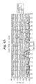
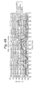
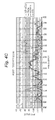
- FIG. 4A shows a spectrum at the middle of the day at a specific location. The interference is greatest between 916 MHz and 920 MHz, with interference also appearing around 913.5 MHz.
- FIG. 4B shows the same location in the evening. Interference has increased in the middle of the band and there is pronounced interference at 912 MHz and 921.5 MHz, such as would be caused by portable phones using digital modulation. The spectrum below 911 MHz and a notch between 920 MHz and 921 MHz remain relatively clear.
- FIG. 4C shows the location in the morning. The spectrum below 911 MHz and above 920 MHz remains clear.
- a band profile may contain both time-dependent information about the band and information about the band that is generally true throughout the day.
- radio 16 By transmitting band profiles to two-way endpoints 13 or repeaters 17, radio 16 provides information that endpoints 13 or repeaters 17 can use to avoid noisy channels and find relatively clear channels of the shared band.
- system 10 provides for band profiles generated by the receiver to be transmitted and employed by endpoints and repeaters.
- radio 16 transmits a band profile to the endpoints, the repeaters, or both.
- Endpoints 13 and repeaters 17 store the band profile in a usable format, such as a lookup table. Transmissions by endpoints 13 and repeaters 17 are then directed to avoid the noisy channels and to favor the clear channels.
- radio 16 continues to monitor the relevant shared band for changes in the band profile by taking repeated snapshots of the band over time. From these snapshots, peaks and averages may be calculated. When variances in the band profile reach a predetermined threshold, the radio sends updated information about the band profile to endpoints 13 and repeaters 17. Once received, the updated band information is used to adjust the transmission pattern of the endpoint or repeater, for example, by updating the lookup table.
- repeaters 17 may be used to relay band profiles to endpoints. This ensures that endpoints have access to band profiles and band-profile updates.
Abstract
taking a series of measurements of the power level of signals received on the predetermined channels within the predetermined frequency band;
evaluating the series of measurements over a predetermined time period;
constructing a band profile of the signal levels received on the predetermined channels;
identifying noisy channels within the predetermined channels based on the band profile; and
enabling the FHSS transmitter to adjust its transmission of signals to transmit signals avoiding identified noisy channels.
Description
- The present invention relates to frequency-hopping spread-spectrum radio systems and, more particularly, to a spread-spectrum radio system that enhances system communications in a given location.
- Wireless automatic meter reading systems are well known. Typically, each utility meter is provided with a battery-powered encoder that collects meter readings and periodically transmits those readings over a wireless network to a central station. The power limitations imposed by the need for the encoder to be battery-powered and by regulations governing radio transmissions effectively prevent direct radio transmissions to the central station. Instead, wireless meter-reading systems typically employ a layered network of overlapping intermediate receiving stations that receive transmissions from a group of meter encoders and forward those messages to the next-higher layer in the network as described, for example, in
U.S. Pat. No. 5,056,107 . These types of layered wireless-transmission networks allow for the use of lower power, unlicensed wireless transmitters for the potentially thousands of end-point encoder transmitters that must be deployed as part of a utility-meter-reading system for a large metropolitan area. - In 1985, as an attempt to stimulate the production and use of wireless-network products, the FCC modified Part 15 of the radio spectrum regulation, which governs unlicensed devices. The modification authorized wireless-network products to operate in the industrial, scientific, and medical (ISM) bands using spread-spectrum modulation. The ISM frequencies that may be used include 902 to 928 MHz, 2.4 to 2.4835 GHz, and 5.725 to 5.850 GHz. The FCC allows users to operate spread-spectrum wireless products, such as utility-metering systems, without obtaining FCC licenses if the products meet certain requirements. This deregulation of the frequency spectrum eliminates the need for the user organizations to perform costly and time-consuming frequency-planning to coordinate radio installations that avoid interference with existing radio systems.
- Spread-spectrum modulators use one of two methods to spread the signal over a wider area. The first method is that of direct-sequence spread-spectrum (DSSS) while the second is frequency-hopping spread-spectrum (FHSS). DSSS combines a data signal at the sending station with a higher data-rate bit sequence, sometimes called a "chipping code" or "processing gain." A high processing gain increases the signal's resistance to interference. FHSS, on the other hand, relies on the distribution of a data signal randomly hopped across a number of defined-frequency channels to avoid interference.
- FHSS operates by taking the data signal and modulating it with a carrier signal that hops from frequency to frequency as a function of time over a wide band of frequencies. With FHSS, the carrier frequency changes periodically. The frequency-hopping technique reduces interference because an interfering signal from a narrowband system will only affect the spread-spectrum signal if both are transmitting at the same frequency and at the same time. Thus, the aggregate interference will be very low, resulting in little or no bit errors.
- In the frequency-hopping systems described above, interference in the ISM band from various sources, such as geographical obstructions, unlicensed radios, portable phones, and the like, decrease the probability that transmissions will be received. If transmissions could be directed to clear channels and away from noisy ones, the probability of successful reception would be increased, thereby enhancing system efficiency.
- A wireless spread-spectrum communication system for transmitting data in an ISM band system enhanced by the detection and use of clear channels in the band. The system includes a radio with a transmitter, receiver, and a microprocessor. The system further includes two-way endpoints, repeaters and one-way endpoints, or any combination of endpoints and repeaters. In an embodiment of the invention, a radio with a receiver capable of measuring power levels in frequency bins for a location is used to create a localized band profile. The band profile identifies noisy and clear channels. The radio employs a transmitter to send the band profile to two-way endpoints nearby. In another embodiment, the radio transmits the band profile to a repeater, which receives FHSS signals from nearby endpoints and then forwards them to the radio using the optimized band profile. In these embodiments, the band profile is generated by the radio's microprocessor, which compares the band snapshots for a location over time. In another embodiment, the radio continues to measure power levels in frequency bins for the location after the band profile has been generated. When a second band profile is derived that deviates beyond predetermined thresholds from the first band profile, the radio transmits the second band profile to recipients of the first band profile. The recipient endpoints or repeaters use the second band profile to replace the first and adjust their transmissions to the radio accordingly. In an embodiment, the endpoint or repeater stores a band profile in the form of a lookup table. The radio may also transmit band profiles in the form of lookup tables.
- According to one aspect, the invention comprises a frequency-hopping spread-spectrum (FHSS) system for enhancing communications in a given location by collecting information corresponding to power levels in frequency bins and in response transmitting an optimized band profile for the location, the system comprising: a radio including a first receiver, a first transmitter, and a microprocessor; a second receiver including a second transmitter and a data-storage device, the second receiver being operably connected to an endpoint operably connected to a utility meter; wherein the first receiver measures power levels in the frequency bins of a shared band, the microprocessor analyzes the results of measurements taken over time and creates a band profile from the measurements, the transmitter sends the band profile to the second receiver, and the second receiver stores the band profile in a data-storage device.
- The second receiver is spaced from the endpoint and wherein the endpoint may include a third transmitter that sends FHSS signals to the second receiver.
- The second receiver may store the band profile in a lookup table.
- The second transmitter may transmit FHSS signals to the radio over optimized channels identified by the band profile.
- The band profile may comprise a lookup table.
- According to another aspect, the invention comprises a method of identifying optimized bands in a frequency-hopping spread-spectrum (FHSS) system for a given location, the method comprising the steps of: providing a radio including a receiver, a transmitter, and a microprocessor; using the radio to measure power levels in the frequency bins for a given location; taking a plurality of measurements of the power levels over time; using the microprocessor to derive a band profile from the measurements; transmitting the band profile to a FHSS device having a data-storage device.
- The band profile may be transmitted to a FHSS device in the form of a lookup table.
- The band profile may be a first band profile and the plurality of measurements are first measurements, and the method may further comprise the steps of: repeating the step of using the radio to measure power levels in the frequency bins; taking a plurality of second measurements over time; using the microprocessor to derive a second band profile from the second measurements; transmitting the second band profile to the FHSS device.
- According to another aspect, the invention comprises method of using a receiver including a data-storage device and a FHSS transmitter, operably connected to an endpoint operably connected to a utility meter, to process data derived from measurements of power levels in frequency bins by a radio in a frequency-hopping spread-spectrum (FHSS) system for a given location, the method comprising the steps of: receiving data including a list of channels from a radio including a transmitter; storing the data in the data-storage device; adjusting the FHSS transmitter to transmit FHSS signals over the received channels; transmitting FHSS signals to the radio over the channels received from the radio.
- The data may be stored in the form of a lookup table.
- The data received may comprise first data and the list of channels may comprise a first list of channels, and the method may further comprise the steps of: receiving second data including a second list of channels; adjusting the FHSS transmitter to transmit FHSS signals to the radio using the second list of channels.
-
-
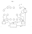
FIG. 1 is an overall schematic diagram of a frequency-hopping spread-spectrum (FHSS); -
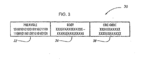
FIG. 2 is a diagram of one embodiment of an encoded FHSS packet; -
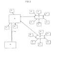
FIG. 3 is a schematic diagram of an FHSS system using repeaters, one-way endpoints, and two-way endpoints; and -
FIGS. 4A ,4B , and4C show snapshots of a shared band for a location taken at different times of day. - In conjunction with the detailed description below, this application incorporates by reference commonly assigned
U.S. Provisional Application No. 60/500,507 U.S. Provisional Application No. 60/500,515 U.S. Provisional Application No. 60/500,504 U.S. Provisional Application No. 60/500,479 U.S. Provisional Application No. 60/500,550 U.S. patent application Ser. No. 10/655,760 U.S. patent application Ser. No. 10/655,759 U.S. Provisional Patent Application No. 60/222,256 U.S. patent application Ser. No. 11/222,657 U.S. Patent Application No. 60/500,506 -
FHSS system 10 includes a multitude ofend point transmitters 12 and at least oneradio 16 with a receiver. In a preferred embodiment,end point transmitters 12 are battery-operated encoder transmitters operably connected to a utility meter. In this embodiment, it is expected that up to hundreds of thousands ofend point transmitters 12 will be deployed as part of aFHSS system 10 in a metropolitan area. Alternatively,end point transmitters 12 can be low-power sensors, detectors or other data encoders that transmit encoded data usingFHSS signal 20. Preferably, end-point transmitters 12 are deployed at a multitude of fixed locations over an entire coverage zone. End-point transmitters 12 could also be mobile transmitters operating within one or more coverage zones, such as pagers or portable transponders. - In an embodiment,
radios 16 comprise a plurality of fixedintermediate radios 16 arranged in a hierarchical network of overlapping zones of coverage that receive encoded data fromend point transmitters central station 18. Reference is made to the previously-identified co-pending application entitled "Spread Spectrum Meter Reading System Utilizing Low-Speed/High Power Frequency Hopping" for a more detailed description of a network of fixedintermediate radios 16 and acentral station 20, the disclosure of which is hereby incorporated by reference. Theradios 16 may be designed as half-duplex radios (transmit or receive but not both simultaneously); however, this architecture has been shown to have some limitations. Preferably, theradios 16 are implemented as a full-duplex design (transmit and receive simultaneously). - In one embodiment, the
radios 16 are capable of wireless retransmission of data 22 to thecentral station 18. Alternatively, theradios 16 can store data until it is manually or automatically downloaded to thecentral station 18, or the radios may be equipped withother communication channels 24, such as telephone lines, power lines, satellite, cellular phone or the like to transmit immediately or in a store and forward mode data received from theend point transmitters 12, either individually or combined into larger blocks or summarized over time for the purpose of creating a metered function associated with one or moreend point transmitters 12. - It will be understood that the
end point transmitters 12 may be of the bubble-up variety wherein encoded data is automatically periodically transmitted by the transmitter 12 (either according to a predefined timing pattern or pseudo-randomly), or thetransmitters 12 may be polled or interrogated to respond to a wakeup tone, for example, transmitted by fixedradio 16 and then transmit FHSS signals 20 with encoded data in response to the polling or interrogation signal. -
System 10 can employ both one-way ("bubble-up") endpoints and two-way endpoints. Two-way repeaters can also be added to the system as shown inFIG. 2 . The one-way endpoints are ERT endpoints described above. Two-way endpoints may be of the type disclosed inU.S. patent application Ser. No. 11/222,657 - In a preferred embodiment as shown in
FIG. 3 , FHSS signals 20 are sent as encoded packets ofdata 30 transmitted as a frequency-hopping spread-spectrum signal in the band between 910-920 MHz. Thus,system 10 uses unlicensed frequency-hopping spread-spectrum transmitters operating in accordance with FCC Part 15.249 (transmitter power less than 500 mW) or Part 15.247 (transmitter power less than 5 W). For purposes of the present invention,transmitters 12 operating under either of these regulations are considered to be low-powered transmitters. Preferably, the encodedpackets 30 are sent in accordance with a predefined protocol. One such protocol is the ERT protocol for meter encoder transmitters manufactured by Itron, Inc., the assignee of the present invention. Another such protocol is the PET protocol as defined in the previously-identified co-pending application entitled "Spread Spectrum Meter Reading System Utilizing Low-Speed/High Power Frequency Hopping." In a preferred embodiment, the encoded data of thepacket 30 is on-off keyed (OOK) modulated. Other amplitude modulation (AM) techniques may also be used. It is also possible for the encoded data to be modulated using other modulation techniques, such as frequency modulation (FM) or frequency shift key (fsk) modulation, although additional circuitry may be required to implement these techniques as will be appreciated by a person of ordinary skill in the art. - The receiver of
radios 16 is preferably a low cost, low power, receiver that is capable of identifying, locating, and tracking FHSS signals received from a transmitter such as that disclosed inU.S. patent application Ser. No. 11/209,348 -
Radio 16 examines the entire useful portion of the wideband at once, looking for a signal suggestive of a data packet transmitted by anendpoint repeater 17. Once a data packet is detected,radio 16 employs a Fast Fourier Transform (FFT) to determine the narrowband frequency on which the data packet is being transmitted. Thus,radio 16 has the ability to take a "snapshot" of the ISM band and measure the signal level across the band. The snapshot includes a measurement of power levels in frequency bins or channels of the FFT. By collecting a series of snapshots over time, the receiver's microprocessor constructs a profile of peak and average power over time and thereby derives a profile of the band. The band profile may be localized becauseradio 16 receives transmissions fromnearby endpoints 13 andrepeaters 17. The band profile may include localized information about generally clear channels, generally noisy channels, and channels with noise levels that vary over time. - Once generated, the band profile is transmitted in a two-way system to an
endpoint 13 orrepeater 17, as shown inFIG. 2 .Endpoint 13 orrepeater 17 then adjusts its transmissions to avoid channels identified as noisy in the profile. -
Endpoint 13 orrepeater 17 stores a band profile in a useable form, such as a lookup table. Theendpoint 13 orrepeater 17 uses the band profile until an updated band profile or an entirely new band profile is received. -
System 10 can also be used to enhance transmissions in other shared bands, such as the international 433 band. - Band profiles can be created for a particular locations in a variety of ways. For example, comparison of snapshots taken of a band in a particular location at different times of the day will generate a time-dependent band profile.
FIG. 4A shows a spectrum at the middle of the day at a specific location. The interference is greatest between 916 MHz and 920 MHz, with interference also appearing around 913.5 MHz.FIG. 4B shows the same location in the evening. Interference has increased in the middle of the band and there is pronounced interference at 912 MHz and 921.5 MHz, such as would be caused by portable phones using digital modulation. The spectrum below 911 MHz and a notch between 920 MHz and 921 MHz remain relatively clear.FIG. 4C shows the location in the morning. The spectrum below 911 MHz and above 920 MHz remains clear. - Other aspects of a band's profile remain relatively constant over time. Geographical obstructions, for example, may make some channels in a particular location undesirable at any time of day. Thus, a band profile may contain both time-dependent information about the band and information about the band that is generally true throughout the day.
- By transmitting band profiles to two-
way endpoints 13 orrepeaters 17,radio 16 provides information thatendpoints 13 orrepeaters 17 can use to avoid noisy channels and find relatively clear channels of the shared band. - In use,
system 10 provides for band profiles generated by the receiver to be transmitted and employed by endpoints and repeaters. To begin with,radio 16 transmits a band profile to the endpoints, the repeaters, or both.Endpoints 13 andrepeaters 17 store the band profile in a usable format, such as a lookup table. Transmissions byendpoints 13 andrepeaters 17 are then directed to avoid the noisy channels and to favor the clear channels. - Preferably,
radio 16 continues to monitor the relevant shared band for changes in the band profile by taking repeated snapshots of the band over time. From these snapshots, peaks and averages may be calculated. When variances in the band profile reach a predetermined threshold, the radio sends updated information about the band profile toendpoints 13 andrepeaters 17. Once received, the updated band information is used to adjust the transmission pattern of the endpoint or repeater, for example, by updating the lookup table. - In
system 10,repeaters 17 may be used to relay band profiles to endpoints. This ensures that endpoints have access to band profiles and band-profile updates. - Although the present invention has been described with respect to the preferred embodiment, it will be understood that numerous changes and variations to aspects of the invention can be made and that the scope of the present invention is intended to be consistent with the claims as follows:
NO CLAIMS ARE FILED WITH THIS APPLICATION
Claims (15)
- A method for transmitting data, comprising:providing a frequency-hopping spread-spectrum (FHSS) transmitter configured to transmit signals on predetermined channels within a predetermined frequency band;providing a receiver configured to receive signals occurring throughout the predetermined frequency band;taking a series of measurements of the power level of signals received on the predetermined channels within the predetermined frequency band;evaluating the series of measurements over a predetermined time period;constructing a band profile of the signal levels received on the predetermined channels;identifying noisy channels within the predetermined channels based on the band profile; andenabling the FHSS transmitter to adjusts its transmission of signals to transmit signals avoiding identified noisy channels.
- The method of claim 1, further comprising:identifying relatively clear channels within the predetermined channels based on the band profile; andenabling the FHSS transmitter to adjusts its transmission of signals to transmit signals on the relatively clear channels.
- The method of claim 1, wherein enabling comprises:storing the band profile in a table accessible by the FHSS transmitter.
- The method of claim 1, further comprising:taking a second series of measurements of the power level of signals received on the predetermined channels within the predetermined frequency band;evaluating the second series of measurements over a predetermined time period; andupdating the band profile based on the signal levels received on the predetermined channels during the second series of measurements.
- The method of claim 1, further comprising:evaluating the series of measurements over a plurality of different time periods within a day; andconstructing a time-dependent band profile.
- The method of claim 5, further comprising:evaluating the series of measurements to identify band information applicable throughout a day; andconstructing a band profile including time-dependent and daily information.
- A data transmission system, comprising:at least one frequency-hopping spread-spectrum (FHSS) transmitter configured to transmit signals on predetermined channels within a predetermined frequency band;a data source couple to said at least one frequency-hopping spread-spectrum (FHSS) transmitter;at least one receiver configured to receive signals occurring throughout the predetermined frequency band; anda microprocessor configured to construct a band profile of signal levels received on the predetermined channels over a predetermined time period, to identify noisy channels within the predetermined channels based on the band profile, and to enable the FHSS transmitter to adjusts its transmission of signals to transmit signals avoiding identified noisy channels.
- The system of claim 7, wherein said microprocessor is further configured to identify relatively clear channels within the predetermined channels based on the band profile, and to enable the FHSS transmitter to adjusts its transmission of signals to transmit signals on the relatively clear channels.
- The system of claim 7, further comprising:a data-storage device configured to store said band profile as a table accessible to the FHSS transmitter.
- The system of claim 7, wherein said microprocessor is further configured to update the band profile based on further signal levels received on the predetermined channels during further series of measurements.
- The system of claim 7, wherein the predetermined frequency band corresponds to one of the industrial, scientific, and medical (ISM) bands.
- The system of claim 7, wherein said data source comprises a utility meter configured to provide utility consumption data to said FHSS transmitter.
- The system of claim 12, further comprising:a central station configured to receive utility consumption data transmissions; andat least one second transmitter associated with said at least one receiver,wherein said at least one second transmitter and said at least one receiver are configured to relay utility consumption data to said central station, and wherein said microprocessor is associated with said at least one second transmitter and said at least one receiver.
- The system of claim 13, further comprising:at least one second receiver associated with said at least one FHSS transmitter;a data-storage device associated with said at least one second receiver; anda second transmitter associated with said at least one receiver and said microprocessor,wherein said microprocessor is configured to enable said FHSS transmitter to adjusts its transmission of signals by causing said second transmitter to transmit said band profile to said at least one second receiver for storage in said data-storage device.
- The system of claim 14, wherein said at least one second receiver and said associated at least one FHSS transmitter correspond to one of a plurality of endpoint devices in an automatic meter reading system.
Applications Claiming Priority (2)
| Application Number | Priority Date | Filing Date | Title |
|---|---|---|---|
| US11/420,501 US8243773B2 (en) | 2006-05-26 | 2006-05-26 | Clear-channel system and related applications |
| EP07794744.8A EP2022173B1 (en) | 2006-05-26 | 2007-05-10 | Clear-channel system and related applications |
Related Parent Applications (2)
| Application Number | Title | Priority Date | Filing Date |
|---|---|---|---|
| EP07794744.8 Division | 2007-05-10 | ||
| EP07794744.8A Division-Into EP2022173B1 (en) | 2006-05-26 | 2007-05-10 | Clear-channel system and related applications |
Publications (2)
| Publication Number | Publication Date |
|---|---|
| EP2375576A1 true EP2375576A1 (en) | 2011-10-12 |
| EP2375576B1 EP2375576B1 (en) | 2013-07-10 |
Family
ID=38749452
Family Applications (2)
| Application Number | Title | Priority Date | Filing Date |
|---|---|---|---|
| EP07794744.8A Not-in-force EP2022173B1 (en) | 2006-05-26 | 2007-05-10 | Clear-channel system and related applications |
| EP10182898.6A Not-in-force EP2375576B1 (en) | 2006-05-26 | 2007-05-10 | Clear-channel system and related applications |
Family Applications Before (1)
| Application Number | Title | Priority Date | Filing Date |
|---|---|---|---|
| EP07794744.8A Not-in-force EP2022173B1 (en) | 2006-05-26 | 2007-05-10 | Clear-channel system and related applications |
Country Status (4)
| Country | Link |
|---|---|
| US (3) | US8243773B2 (en) |
| EP (2) | EP2022173B1 (en) |
| CA (1) | CA2652577C (en) |
| WO (1) | WO2007139678A2 (en) |
Cited By (3)
| Publication number | Priority date | Publication date | Assignee | Title |
|---|---|---|---|---|
| WO2014055486A1 (en) * | 2012-10-01 | 2014-04-10 | Cooper Technologies Company | System and method for support of one-way endpoints in two-way wireless networks |
| US10278113B2 (en) | 2014-01-17 | 2019-04-30 | Eaton Intelligent Power Limited | Dynamically-selectable multi-modal modulation in wireless multihop networks |
| US10679131B2 (en) | 2012-07-12 | 2020-06-09 | Eaton Intelligent Power Limited | System and method for efficient data collection in distributed sensor measurement systems |
Families Citing this family (4)
| Publication number | Priority date | Publication date | Assignee | Title |
|---|---|---|---|---|
| US8243773B2 (en) | 2006-05-26 | 2012-08-14 | Itron, Inc. | Clear-channel system and related applications |
| US20100265095A1 (en) * | 2009-04-20 | 2010-10-21 | Itron, Inc. | Endpoint classification and command processing |
| US9407327B2 (en) * | 2009-02-13 | 2016-08-02 | Qualcomm Incorporated | Wireless power for chargeable and charging devices |
| CN109451443B (en) * | 2018-12-27 | 2021-05-11 | 武汉盛帆电子股份有限公司 | Data transmission method, device and system based on Lora wireless |
Citations (4)
| Publication number | Priority date | Publication date | Assignee | Title |
|---|---|---|---|---|
| US5056107A (en) | 1990-02-15 | 1991-10-08 | Iris Systems Inc. | Radio communication network for remote data generating stations |
| WO1996010300A1 (en) * | 1994-09-23 | 1996-04-04 | Sanderford Hugh Britton Jr | Enhanced frequency agile radio |
| US6018543A (en) * | 1997-05-21 | 2000-01-25 | Itt Manufacturing Enterprises, Inc. | Noisy channel avoidance method in a digital communication system |
| WO2001052436A1 (en) * | 2000-01-08 | 2001-07-19 | Aware, Inc. | Dynamic frequency-hopping system |
Family Cites Families (19)
| Publication number | Priority date | Publication date | Assignee | Title |
|---|---|---|---|---|
| US5438329A (en) | 1993-06-04 | 1995-08-01 | M & Fc Holding Company, Inc. | Duplex bi-directional multi-mode remote instrument reading and telemetry system |
| US5719564A (en) | 1996-05-10 | 1998-02-17 | Sears; Lawrence M. | Utility meter reading system |
| US5883886A (en) | 1997-01-03 | 1999-03-16 | Motorola, Inc. | Utility meter readings on a reverse channel of a two-way paging system |
| US6073169A (en) * | 1997-04-08 | 2000-06-06 | Abb Power T&D Company Inc. | Automatic meter reading system employing common broadcast command channel |
| US6084919A (en) * | 1998-01-30 | 2000-07-04 | Motorola, Inc. | Communication unit having spectral adaptability |
| US6377609B1 (en) | 1999-03-05 | 2002-04-23 | Neptune Technology Group Inc. | Spread spectrum frequency hopping system and method |
| US6967974B1 (en) | 1999-09-30 | 2005-11-22 | Andrzej Partyka | Transmission of urgent messages in telemetry system |
| WO2002008866A2 (en) * | 2000-07-21 | 2002-01-31 | Itron, Inc. | Spread spectrum meter reading system utilizing low-speed/high-power frequency hopping |
| DE60142477D1 (en) | 2000-08-01 | 2010-08-12 | Itron Inc | FREQUENCY VOLTAGE SPREADING SYSTEM WITH RUNNING HIGH SENSITIVITY, AND SYNCHRONIZATION FOR FREQUENCY LABEL SIGNALS |
| US6496064B2 (en) * | 2000-08-15 | 2002-12-17 | Eugene Rzyski | Intermodulation product cancellation circuit |
| US7292656B2 (en) * | 2002-04-22 | 2007-11-06 | Cognio, Inc. | Signal pulse detection scheme for use in real-time spectrum analysis |
| US7408907B2 (en) * | 2002-09-11 | 2008-08-05 | Cisco Technology, Inc. | System and method for management of a shared frequency band using client-specific management techniques |
| US6996215B2 (en) | 2002-11-27 | 2006-02-07 | Macconnell John Walter | Telemetry system and method |
| US7304587B2 (en) | 2003-02-14 | 2007-12-04 | Energy Technology Group, Inc. | Automated meter reading system, communication and control network for automated meter reading, meter data collector program product, and associated methods |
| US7230972B2 (en) | 2003-05-07 | 2007-06-12 | Itron, Inc. | Method and system for collecting and transmitting data in a meter reading system |
| US20050055432A1 (en) * | 2003-09-08 | 2005-03-10 | Smart Synch, Inc. | Systems and methods for remote power management using 802.11 wireless protocols |
| US7346030B2 (en) * | 2003-09-26 | 2008-03-18 | Itron, Inc. | Processing gain for wireless communication, such as in automatic data collection systems for public utility data collection |
| KR100891806B1 (en) * | 2003-11-26 | 2009-04-07 | 삼성전자주식회사 | Apparatus for channel allocaction adaptively by channel estimation in orthogonal frequency division multiple access system and the method thereof |
| US8243773B2 (en) | 2006-05-26 | 2012-08-14 | Itron, Inc. | Clear-channel system and related applications |
-
2006
- 2006-05-26 US US11/420,501 patent/US8243773B2/en not_active Expired - Fee Related
-
2007
- 2007-05-10 EP EP07794744.8A patent/EP2022173B1/en not_active Not-in-force
- 2007-05-10 CA CA2652577A patent/CA2652577C/en not_active Expired - Fee Related
- 2007-05-10 EP EP10182898.6A patent/EP2375576B1/en not_active Not-in-force
- 2007-05-10 WO PCT/US2007/011319 patent/WO2007139678A2/en active Application Filing
-
2011
- 2011-11-10 US US13/293,573 patent/US8908741B2/en not_active Expired - Fee Related
-
2012
- 2012-10-25 US US13/660,081 patent/US20130051431A1/en not_active Abandoned
Patent Citations (4)
| Publication number | Priority date | Publication date | Assignee | Title |
|---|---|---|---|---|
| US5056107A (en) | 1990-02-15 | 1991-10-08 | Iris Systems Inc. | Radio communication network for remote data generating stations |
| WO1996010300A1 (en) * | 1994-09-23 | 1996-04-04 | Sanderford Hugh Britton Jr | Enhanced frequency agile radio |
| US6018543A (en) * | 1997-05-21 | 2000-01-25 | Itt Manufacturing Enterprises, Inc. | Noisy channel avoidance method in a digital communication system |
| WO2001052436A1 (en) * | 2000-01-08 | 2001-07-19 | Aware, Inc. | Dynamic frequency-hopping system |
Cited By (5)
| Publication number | Priority date | Publication date | Assignee | Title |
|---|---|---|---|---|
| US10679131B2 (en) | 2012-07-12 | 2020-06-09 | Eaton Intelligent Power Limited | System and method for efficient data collection in distributed sensor measurement systems |
| WO2014055486A1 (en) * | 2012-10-01 | 2014-04-10 | Cooper Technologies Company | System and method for support of one-way endpoints in two-way wireless networks |
| US9644991B2 (en) | 2012-10-01 | 2017-05-09 | Cooper Technologies Company | System and method for support of one-way endpoints in two-way wireless networks |
| US10222232B2 (en) | 2012-10-01 | 2019-03-05 | Eaton Intelligent Power Limited | System and method for support of one-way endpoints in two-way wireless networks |
| US10278113B2 (en) | 2014-01-17 | 2019-04-30 | Eaton Intelligent Power Limited | Dynamically-selectable multi-modal modulation in wireless multihop networks |
Also Published As
| Publication number | Publication date |
|---|---|
| US20130051431A1 (en) | 2013-02-28 |
| US8243773B2 (en) | 2012-08-14 |
| US8908741B2 (en) | 2014-12-09 |
| WO2007139678A2 (en) | 2007-12-06 |
| CA2652577C (en) | 2017-02-14 |
| EP2022173B1 (en) | 2016-01-27 |
| US20070274373A1 (en) | 2007-11-29 |
| EP2375576B1 (en) | 2013-07-10 |
| EP2022173A2 (en) | 2009-02-11 |
| EP2022173A4 (en) | 2013-06-26 |
| CA2652577A1 (en) | 2007-12-06 |
| US20120099620A1 (en) | 2012-04-26 |
| WO2007139678A3 (en) | 2008-03-13 |
Similar Documents
| Publication | Publication Date | Title |
|---|---|---|
| US8908741B2 (en) | Clear-channel system and related applications | |
| EP1305923B1 (en) | Frequency hopping spread spectrum system with high sensitivity tracking and synchronization for frequency unstable signals | |
| US7154938B2 (en) | RF communications system utilizing digital modulation to transmit and receive data | |
| EP3408681B1 (en) | Backscatter devices including examples of single sideband operation | |
| EP1480386B1 (en) | Position based WPAN (Wireless Personal Area Network) management | |
| AU2001284691A1 (en) | Frequency hopping spread spectrum system with high sensitivity tracking and synchronization for frequency unstable signals | |
| KR100784055B1 (en) | Syncronization system of radio frequency identification | |
| US7599703B2 (en) | Wireless polling system using spread-spectrum communication | |
| WO2003049051A1 (en) | Method of securing access to a user having an enhanced security proximity token | |
| CN1205767C (en) | Interference prevention in radio communications system | |
| WO2003061149A1 (en) | Frequency hopping spread spectrum communications system | |
| JP2005143082A (en) | System and method for optimizing contiguous channel operation with cellular reuse | |
| US7610385B2 (en) | System and method for adaptive bandwidth utilization for interoperability | |
| KR100780016B1 (en) | The wireless terminal with industrial scientific medical band | |
| AU3441701A (en) | Dynamic frequency-hopping system | |
| KR100969214B1 (en) | Cognitive UWB System Using Code Sequence and Time Sequence in Cognitive UWB | |
| Bielefeld et al. | Energy Efficient Ultra-Wideband Signaling for Cooperative Spectrum Sensing in Cognitive Radio | |
| Durantini et al. | UWB interference mitigation techniques in a cooperative scenario | |
| Schwartz et al. | Frequency Hopping Spread Spectrum (FHSS) | |
| Abid et al. | Estimation of BIT Error Probability in Uncoded FHSS | |
| Kaiser et al. | A Comparison of ZigBee/802.15. 4 vs. Ultra-Wideband Transmission Techniques for Wireless Fire and Intrusion Detectors |
Legal Events
| Date | Code | Title | Description |
|---|---|---|---|
| PUAI | Public reference made under article 153(3) epc to a published international application that has entered the european phase |
Free format text: ORIGINAL CODE: 0009012 |
|
| AC | Divisional application: reference to earlier application |
Ref document number: 2022173 Country of ref document: EP Kind code of ref document: P |
|
| AK | Designated contracting states |
Kind code of ref document: A1 Designated state(s): AT BE BG CH CY CZ DE DK EE ES FI FR GB GR HU IE IS IT LI LT LU LV MC MT NL PL PT RO SE SI SK TR |
|
| AX | Request for extension of the european patent |
Extension state: AL BA HR MK RS |
|
| 17P | Request for examination filed |
Effective date: 20111101 |
|
| 17Q | First examination report despatched |
Effective date: 20120531 |
|
| REG | Reference to a national code |
Ref country code: DE Ref legal event code: R079 Ref document number: 602007031629 Country of ref document: DE Free format text: PREVIOUS MAIN CLASS: H04B0001713000 Ipc: H04B0001715000 |
|
| GRAP | Despatch of communication of intention to grant a patent |
Free format text: ORIGINAL CODE: EPIDOSNIGR1 |
|
| RIC1 | Information provided on ipc code assigned before grant |
Ipc: H04B 1/715 20110101AFI20130207BHEP |
|
| GRAS | Grant fee paid |
Free format text: ORIGINAL CODE: EPIDOSNIGR3 |
|
| GRAA | (expected) grant |
Free format text: ORIGINAL CODE: 0009210 |
|
| AC | Divisional application: reference to earlier application |
Ref document number: 2022173 Country of ref document: EP Kind code of ref document: P |
|
| AK | Designated contracting states |
Kind code of ref document: B1 Designated state(s): AT BE BG CH CY CZ DE DK EE ES FI FR GB GR HU IE IS IT LI LT LU LV MC MT NL PL PT RO SE SI SK TR |
|
| REG | Reference to a national code |
Ref country code: GB Ref legal event code: FG4D |
|
| REG | Reference to a national code |
Ref country code: AT Ref legal event code: REF Ref document number: 621461 Country of ref document: AT Kind code of ref document: T Effective date: 20130715 Ref country code: CH Ref legal event code: EP |
|
| REG | Reference to a national code |
Ref country code: IE Ref legal event code: FG4D |
|
| REG | Reference to a national code |
Ref country code: DE Ref legal event code: R096 Ref document number: 602007031629 Country of ref document: DE Effective date: 20130905 |
|
| PG25 | Lapsed in a contracting state [announced via postgrant information from national office to epo] |
Ref country code: SI Free format text: LAPSE BECAUSE OF FAILURE TO SUBMIT A TRANSLATION OF THE DESCRIPTION OR TO PAY THE FEE WITHIN THE PRESCRIBED TIME-LIMIT Effective date: 20130710 |
|
| REG | Reference to a national code |
Ref country code: AT Ref legal event code: MK05 Ref document number: 621461 Country of ref document: AT Kind code of ref document: T Effective date: 20130710 |
|
| REG | Reference to a national code |
Ref country code: NL Ref legal event code: VDEP Effective date: 20130710 |
|
| REG | Reference to a national code |
Ref country code: LT Ref legal event code: MG4D |
|
| PG25 | Lapsed in a contracting state [announced via postgrant information from national office to epo] |
Ref country code: IS Free format text: LAPSE BECAUSE OF FAILURE TO SUBMIT A TRANSLATION OF THE DESCRIPTION OR TO PAY THE FEE WITHIN THE PRESCRIBED TIME-LIMIT Effective date: 20131110 Ref country code: BE Free format text: LAPSE BECAUSE OF FAILURE TO SUBMIT A TRANSLATION OF THE DESCRIPTION OR TO PAY THE FEE WITHIN THE PRESCRIBED TIME-LIMIT Effective date: 20130710 Ref country code: CY Free format text: LAPSE BECAUSE OF FAILURE TO SUBMIT A TRANSLATION OF THE DESCRIPTION OR TO PAY THE FEE WITHIN THE PRESCRIBED TIME-LIMIT Effective date: 20130619 Ref country code: SE Free format text: LAPSE BECAUSE OF FAILURE TO SUBMIT A TRANSLATION OF THE DESCRIPTION OR TO PAY THE FEE WITHIN THE PRESCRIBED TIME-LIMIT Effective date: 20130710 Ref country code: AT Free format text: LAPSE BECAUSE OF FAILURE TO SUBMIT A TRANSLATION OF THE DESCRIPTION OR TO PAY THE FEE WITHIN THE PRESCRIBED TIME-LIMIT Effective date: 20130710 Ref country code: PT Free format text: LAPSE BECAUSE OF FAILURE TO SUBMIT A TRANSLATION OF THE DESCRIPTION OR TO PAY THE FEE WITHIN THE PRESCRIBED TIME-LIMIT Effective date: 20131111 Ref country code: LT Free format text: LAPSE BECAUSE OF FAILURE TO SUBMIT A TRANSLATION OF THE DESCRIPTION OR TO PAY THE FEE WITHIN THE PRESCRIBED TIME-LIMIT Effective date: 20130710 |
|
| PG25 | Lapsed in a contracting state [announced via postgrant information from national office to epo] |
Ref country code: NL Free format text: LAPSE BECAUSE OF FAILURE TO SUBMIT A TRANSLATION OF THE DESCRIPTION OR TO PAY THE FEE WITHIN THE PRESCRIBED TIME-LIMIT Effective date: 20130710 Ref country code: FI Free format text: LAPSE BECAUSE OF FAILURE TO SUBMIT A TRANSLATION OF THE DESCRIPTION OR TO PAY THE FEE WITHIN THE PRESCRIBED TIME-LIMIT Effective date: 20130710 Ref country code: PL Free format text: LAPSE BECAUSE OF FAILURE TO SUBMIT A TRANSLATION OF THE DESCRIPTION OR TO PAY THE FEE WITHIN THE PRESCRIBED TIME-LIMIT Effective date: 20130710 Ref country code: LV Free format text: LAPSE BECAUSE OF FAILURE TO SUBMIT A TRANSLATION OF THE DESCRIPTION OR TO PAY THE FEE WITHIN THE PRESCRIBED TIME-LIMIT Effective date: 20130710 Ref country code: ES Free format text: LAPSE BECAUSE OF FAILURE TO SUBMIT A TRANSLATION OF THE DESCRIPTION OR TO PAY THE FEE WITHIN THE PRESCRIBED TIME-LIMIT Effective date: 20131021 Ref country code: GR Free format text: LAPSE BECAUSE OF FAILURE TO SUBMIT A TRANSLATION OF THE DESCRIPTION OR TO PAY THE FEE WITHIN THE PRESCRIBED TIME-LIMIT Effective date: 20131011 |
|
| PG25 | Lapsed in a contracting state [announced via postgrant information from national office to epo] |
Ref country code: CY Free format text: LAPSE BECAUSE OF FAILURE TO SUBMIT A TRANSLATION OF THE DESCRIPTION OR TO PAY THE FEE WITHIN THE PRESCRIBED TIME-LIMIT Effective date: 20130710 |
|
| PG25 | Lapsed in a contracting state [announced via postgrant information from national office to epo] |
Ref country code: DK Free format text: LAPSE BECAUSE OF FAILURE TO SUBMIT A TRANSLATION OF THE DESCRIPTION OR TO PAY THE FEE WITHIN THE PRESCRIBED TIME-LIMIT Effective date: 20130710 Ref country code: EE Free format text: LAPSE BECAUSE OF FAILURE TO SUBMIT A TRANSLATION OF THE DESCRIPTION OR TO PAY THE FEE WITHIN THE PRESCRIBED TIME-LIMIT Effective date: 20130710 Ref country code: RO Free format text: LAPSE BECAUSE OF FAILURE TO SUBMIT A TRANSLATION OF THE DESCRIPTION OR TO PAY THE FEE WITHIN THE PRESCRIBED TIME-LIMIT Effective date: 20130710 Ref country code: SK Free format text: LAPSE BECAUSE OF FAILURE TO SUBMIT A TRANSLATION OF THE DESCRIPTION OR TO PAY THE FEE WITHIN THE PRESCRIBED TIME-LIMIT Effective date: 20130710 Ref country code: CZ Free format text: LAPSE BECAUSE OF FAILURE TO SUBMIT A TRANSLATION OF THE DESCRIPTION OR TO PAY THE FEE WITHIN THE PRESCRIBED TIME-LIMIT Effective date: 20130710 |
|
| PLBE | No opposition filed within time limit |
Free format text: ORIGINAL CODE: 0009261 |
|
| STAA | Information on the status of an ep patent application or granted ep patent |
Free format text: STATUS: NO OPPOSITION FILED WITHIN TIME LIMIT |
|
| 26N | No opposition filed |
Effective date: 20140411 |
|
| REG | Reference to a national code |
Ref country code: DE Ref legal event code: R097 Ref document number: 602007031629 Country of ref document: DE Effective date: 20140411 |
|
| PG25 | Lapsed in a contracting state [announced via postgrant information from national office to epo] |
Ref country code: LU Free format text: LAPSE BECAUSE OF FAILURE TO SUBMIT A TRANSLATION OF THE DESCRIPTION OR TO PAY THE FEE WITHIN THE PRESCRIBED TIME-LIMIT Effective date: 20140510 |
|
| REG | Reference to a national code |
Ref country code: CH Ref legal event code: PL |
|
| PG25 | Lapsed in a contracting state [announced via postgrant information from national office to epo] |
Ref country code: MC Free format text: LAPSE BECAUSE OF FAILURE TO SUBMIT A TRANSLATION OF THE DESCRIPTION OR TO PAY THE FEE WITHIN THE PRESCRIBED TIME-LIMIT Effective date: 20130710 Ref country code: CH Free format text: LAPSE BECAUSE OF NON-PAYMENT OF DUE FEES Effective date: 20140531 Ref country code: LI Free format text: LAPSE BECAUSE OF NON-PAYMENT OF DUE FEES Effective date: 20140531 |
|
| REG | Reference to a national code |
Ref country code: IE Ref legal event code: MM4A |
|
| PG25 | Lapsed in a contracting state [announced via postgrant information from national office to epo] |
Ref country code: IE Free format text: LAPSE BECAUSE OF NON-PAYMENT OF DUE FEES Effective date: 20140510 |
|
| PG25 | Lapsed in a contracting state [announced via postgrant information from national office to epo] |
Ref country code: MT Free format text: LAPSE BECAUSE OF FAILURE TO SUBMIT A TRANSLATION OF THE DESCRIPTION OR TO PAY THE FEE WITHIN THE PRESCRIBED TIME-LIMIT Effective date: 20130710 |
|
| REG | Reference to a national code |
Ref country code: FR Ref legal event code: PLFP Year of fee payment: 10 |
|
| PG25 | Lapsed in a contracting state [announced via postgrant information from national office to epo] |
Ref country code: BG Free format text: LAPSE BECAUSE OF FAILURE TO SUBMIT A TRANSLATION OF THE DESCRIPTION OR TO PAY THE FEE WITHIN THE PRESCRIBED TIME-LIMIT Effective date: 20130710 |
|
| PG25 | Lapsed in a contracting state [announced via postgrant information from national office to epo] |
Ref country code: HU Free format text: LAPSE BECAUSE OF FAILURE TO SUBMIT A TRANSLATION OF THE DESCRIPTION OR TO PAY THE FEE WITHIN THE PRESCRIBED TIME-LIMIT; INVALID AB INITIO Effective date: 20070510 Ref country code: TR Free format text: LAPSE BECAUSE OF FAILURE TO SUBMIT A TRANSLATION OF THE DESCRIPTION OR TO PAY THE FEE WITHIN THE PRESCRIBED TIME-LIMIT Effective date: 20130710 |
|
| PGFP | Annual fee paid to national office [announced via postgrant information from national office to epo] |
Ref country code: GB Payment date: 20160504 Year of fee payment: 10 Ref country code: DE Payment date: 20160504 Year of fee payment: 10 |
|
| PGFP | Annual fee paid to national office [announced via postgrant information from national office to epo] |
Ref country code: IT Payment date: 20160524 Year of fee payment: 10 Ref country code: FR Payment date: 20160412 Year of fee payment: 10 |
|
| REG | Reference to a national code |
Ref country code: DE Ref legal event code: R119 Ref document number: 602007031629 Country of ref document: DE |
|
| GBPC | Gb: european patent ceased through non-payment of renewal fee |
Effective date: 20170510 |
|
| REG | Reference to a national code |
Ref country code: FR Ref legal event code: ST Effective date: 20180131 |
|
| PG25 | Lapsed in a contracting state [announced via postgrant information from national office to epo] |
Ref country code: GB Free format text: LAPSE BECAUSE OF NON-PAYMENT OF DUE FEES Effective date: 20170510 Ref country code: DE Free format text: LAPSE BECAUSE OF NON-PAYMENT OF DUE FEES Effective date: 20171201 |
|
| PG25 | Lapsed in a contracting state [announced via postgrant information from national office to epo] |
Ref country code: IT Free format text: LAPSE BECAUSE OF NON-PAYMENT OF DUE FEES Effective date: 20170510 Ref country code: FR Free format text: LAPSE BECAUSE OF NON-PAYMENT OF DUE FEES Effective date: 20170531 |