EP2388043A1 - Method for searching and selecting an RF telemetry channel to establish a link with an active medical device - Google Patents
Method for searching and selecting an RF telemetry channel to establish a link with an active medical device Download PDFInfo
- Publication number
- EP2388043A1 EP2388043A1 EP11162935A EP11162935A EP2388043A1 EP 2388043 A1 EP2388043 A1 EP 2388043A1 EP 11162935 A EP11162935 A EP 11162935A EP 11162935 A EP11162935 A EP 11162935A EP 2388043 A1 EP2388043 A1 EP 2388043A1
- Authority
- EP
- European Patent Office
- Prior art keywords
- channel
- signal
- indicator
- term
- communication
- Prior art date
- Legal status (The legal status is an assumption and is not a legal conclusion. Google has not performed a legal analysis and makes no representation as to the accuracy of the status listed.)
- Granted
Links
- 238000000034 method Methods 0.000 title claims abstract description 28
- 238000004891 communication Methods 0.000 claims abstract description 46
- 230000007774 longterm Effects 0.000 claims abstract description 27
- 238000004458 analytical method Methods 0.000 claims description 47
- 239000007943 implant Substances 0.000 claims description 19
- 238000001914 filtration Methods 0.000 claims description 3
- 230000000737 periodic effect Effects 0.000 claims description 3
- 241000897276 Termes Species 0.000 description 8
- 230000005540 biological transmission Effects 0.000 description 6
- 230000008569 process Effects 0.000 description 5
- 230000000694 effects Effects 0.000 description 4
- 230000008901 benefit Effects 0.000 description 3
- 238000010168 coupling process Methods 0.000 description 3
- 230000000747 cardiac effect Effects 0.000 description 2
- 230000008878 coupling Effects 0.000 description 2
- 238000005859 coupling reaction Methods 0.000 description 2
- 230000003247 decreasing effect Effects 0.000 description 2
- 238000001514 detection method Methods 0.000 description 2
- 230000001939 inductive effect Effects 0.000 description 2
- 238000012544 monitoring process Methods 0.000 description 2
- 206010011906 Death Diseases 0.000 description 1
- 241000607479 Yersinia pestis Species 0.000 description 1
- 238000013459 approach Methods 0.000 description 1
- 230000006793 arrhythmia Effects 0.000 description 1
- 206010003119 arrhythmia Diseases 0.000 description 1
- 238000004364 calculation method Methods 0.000 description 1
- 238000013194 cardioversion Methods 0.000 description 1
- 230000015556 catabolic process Effects 0.000 description 1
- 238000006731 degradation reaction Methods 0.000 description 1
- 230000006866 deterioration Effects 0.000 description 1
- 238000005265 energy consumption Methods 0.000 description 1
- 230000036039 immunity Effects 0.000 description 1
- 238000002847 impedance measurement Methods 0.000 description 1
- 230000006698 induction Effects 0.000 description 1
- 238000009434 installation Methods 0.000 description 1
- 238000002955 isolation Methods 0.000 description 1
- 239000000463 material Substances 0.000 description 1
- 230000000926 neurological effect Effects 0.000 description 1
- 230000008520 organization Effects 0.000 description 1
- 244000045947 parasite Species 0.000 description 1
- 230000002093 peripheral effect Effects 0.000 description 1
- 238000012545 processing Methods 0.000 description 1
- 230000000717 retained effect Effects 0.000 description 1
- 238000009738 saturating Methods 0.000 description 1
- 230000035945 sensitivity Effects 0.000 description 1
- 238000001228 spectrum Methods 0.000 description 1
- 239000000126 substance Substances 0.000 description 1
- 238000012360 testing method Methods 0.000 description 1
- 238000012546 transfer Methods 0.000 description 1
Images


Classifications
-
- A—HUMAN NECESSITIES
- A61—MEDICAL OR VETERINARY SCIENCE; HYGIENE
- A61N—ELECTROTHERAPY; MAGNETOTHERAPY; RADIATION THERAPY; ULTRASOUND THERAPY
- A61N1/00—Electrotherapy; Circuits therefor
- A61N1/18—Applying electric currents by contact electrodes
- A61N1/32—Applying electric currents by contact electrodes alternating or intermittent currents
- A61N1/36—Applying electric currents by contact electrodes alternating or intermittent currents for stimulation
- A61N1/372—Arrangements in connection with the implantation of stimulators
- A61N1/37211—Means for communicating with stimulators
- A61N1/37252—Details of algorithms or data aspects of communication system, e.g. handshaking, transmitting specific data or segmenting data
-
- A—HUMAN NECESSITIES
- A61—MEDICAL OR VETERINARY SCIENCE; HYGIENE
- A61N—ELECTROTHERAPY; MAGNETOTHERAPY; RADIATION THERAPY; ULTRASOUND THERAPY
- A61N1/00—Electrotherapy; Circuits therefor
- A61N1/18—Applying electric currents by contact electrodes
- A61N1/32—Applying electric currents by contact electrodes alternating or intermittent currents
- A61N1/36—Applying electric currents by contact electrodes alternating or intermittent currents for stimulation
- A61N1/372—Arrangements in connection with the implantation of stimulators
- A61N1/37211—Means for communicating with stimulators
- A61N1/37217—Means for communicating with stimulators characterised by the communication link, e.g. acoustic or tactile
- A61N1/37223—Circuits for electromagnetic coupling
-
- A—HUMAN NECESSITIES
- A61—MEDICAL OR VETERINARY SCIENCE; HYGIENE
- A61N—ELECTROTHERAPY; MAGNETOTHERAPY; RADIATION THERAPY; ULTRASOUND THERAPY
- A61N1/00—Electrotherapy; Circuits therefor
- A61N1/18—Applying electric currents by contact electrodes
- A61N1/32—Applying electric currents by contact electrodes alternating or intermittent currents
- A61N1/36—Applying electric currents by contact electrodes alternating or intermittent currents for stimulation
- A61N1/372—Arrangements in connection with the implantation of stimulators
- A61N1/37211—Means for communicating with stimulators
- A61N1/37252—Details of algorithms or data aspects of communication system, e.g. handshaking, transmitting specific data or segmenting data
- A61N1/37276—Details of algorithms or data aspects of communication system, e.g. handshaking, transmitting specific data or segmenting data characterised by means for reducing power consumption during telemetry
-
- H—ELECTRICITY
- H04—ELECTRIC COMMUNICATION TECHNIQUE
- H04B—TRANSMISSION
- H04B17/00—Monitoring; Testing
- H04B17/30—Monitoring; Testing of propagation channels
- H04B17/382—Monitoring; Testing of propagation channels for resource allocation, admission control or handover
-
- H04B5/24—
-
- H—ELECTRICITY
- H04—ELECTRIC COMMUNICATION TECHNIQUE
- H04W—WIRELESS COMMUNICATION NETWORKS
- H04W72/00—Local resource management
- H04W72/50—Allocation or scheduling criteria for wireless resources
- H04W72/54—Allocation or scheduling criteria for wireless resources based on quality criteria
- H04W72/541—Allocation or scheduling criteria for wireless resources based on quality criteria using the level of interference
Definitions
- the invention relates to "active medical devices” as defined by Directive 93/42 / EC of 14 June 1993 of the Council of the European Communities, and in particular implants of the "active implantable medical devices” type as defined by the Council 90/385 / EEC of 20 June 1990.
- This definition includes in particular the devices responsible for monitoring cardiac activity and generating pacing, resynchronization, defibrillation and / or cardioversion pulses in the event of arrhythmia detected by the device. It also includes neurological devices, medical substance delivery pumps, cochlear implants, implanted biological sensors, etc., as well as devices for measuring pH or intracorporeal impedance (such as trans-pulmonary impedance measurement or intracardiac impedance). It will also be noted that, while the invention applies particularly advantageously to implanted devices such as pacemakers, cardiovers or defibrillators, it can equally well be implemented with non-implanted medical devices, for example data loggers such as external Holter devices for ambulatory monitoring and recording of certain physiological parameters such as, for example, cardiac activity.
- data loggers such as external Holter devices for ambulatory monitoring and recording of certain physiological parameters such as, for example, cardiac activity.
- Most active medical devices are designed to allow a data exchange with a "programmer", which is an external device for verifying the setting of the device, read information recorded by it or to enter information, or update the internal software for controlling the device.
- a "programmer” is an external device for verifying the setting of the device, read information recorded by it or to enter information, or update the internal software for controlling the device.
- This exchange of data between the medical device and the programmer is performed by telemetry, that is to say by a technique of remote transmission of information, without galvanic contact.
- RF telemetry allows programming or interrogating implants at distances greater than 3 m, and therefore allows the exchange of information without manipulation of a telemetry head, or even without the intervention of an operator external.
- An active medical device comprising such RF telemetry means is for example described in FIG. EP 1 862 191 A1 (Medical ELA).
- the communication protocol between the active device (usually an implant) and the base station (programmer of the "home monitor” device) is in particular governed by the EN 301839 standard "Electromagnetic compatibility and Radio spectrum Matters (ERM) - Short-range devices (SRD) - Ultra-low power (ULP-AMI) and peripheral (ULP-AMI-P) active medical implants operating in the 402 MHz to 405 MHz "frequency range.
- MICS band Medical Implants Communication Systems
- ISM Industrial, Scientific and Medical
- medical devices with RF telemetry functions are all multichannel devices, that is to say using several frequencies located in the same band (some devices can be multiband in addition, but this is an aspect which does not relate to the invention).
- This step is important because it is essential to choose a low noise channel, which is almost certain that the communication can be completed without interruption.
- RF telemetry is subject to many disturbances by the electromagnetic environment, including radio, television and mobile telephony signals, not to mention the many industrial pests likely to be produced in the immediate environment of the implant wearer.
- the implant that wants to communicate on an RF channel may also be in conflict with other nearby communicating devices that also occupy RF telemetry channels. All of these disturbances are likely to cause interference and disrupt data transmission.
- RF telemetry involves a relatively high energy expenditure, at least at the scale of an implant whose life time is an extremely critical parameter, so that the multiplication of interrupted communications may eventually have a significant impact on the autonomy of the implant.
- To select a channel it is generally done by a preliminary scan consisting of "listening" successively the different channels that can be used for transmission, before choosing one of them to start transmitting a signal.
- the US 6,868,288 B2 ( US 2002/0045920 A1 ) proposes, in order to make this preliminary choice of the communication channel, to simultaneously analyze the average level of signal picked up on each of the channels, then to classify these as a function of the respective detected level (any signal present on a channel being considered as noise).
- the selected channel will then be analyzed in isolation to ensure that it is available when the device is available. will start transmitting: indeed, between the moment of the scan and the start of the broadcast, a communication may have started on this channel from another device, so that the busy channel will not be no longer available for the show.
- any signal present in the channel is considered as noise.
- the analysis makes no distinction between background noise (ie "true” noise) and the presence of a useful signal due to a communication in progress on that background.
- channel the latter is assimilated by the device to noise, while this emission can very well take place on a good quality channel from the point of view of the signal / noise ratio.
- the device can very well exclude a low noise channel, just because this channel is busy at the time of scanning.
- the aim of the invention is to overcome the various disadvantages described above, by proposing a channel analysis and selection technique making it possible to maximize the probability of establishing a connection on this channel and to continue it until at its end.
- the object of the invention is to propose a new selection technique not only of a free channel and little noisy at the time of the scan, but of a channel that is likely to remain free at the moment where the device will attempt to establish communication.
- Another object of the invention is to propose such a technique that requires only modest resources in terms of computing power, involving only simple algorithms, or even logic that can be implemented in hardware form from comparators and threshold circuits, in a particularly advantageous manner with respect to the implant.
- the invention proposes a method of searching for and selecting a communication channel prior to establishing an RF telemetry link with a remote device, this method being of the general type known from FIG. US2008 / 015655 A1 above, that it comprises the following steps: in the absence of a request for communication or communication in progress with the remote device, periodic polling and first analysis of said plurality of channels with, for each channel, determination and storage of at least one first indicator representative of the availability of this channel; on receiving a communication request with the remote device, second analysis of said plurality of channels with, for each channel, determining and storing at least one second indicator representative of the availability of this channel, and selecting among the plurality channels, of a channel as a communication channel on the basis of said indicators,
- the method of the invention is characterized in that: said first indicator is a long-term indicator representative of the long-term availability of the channel, and said second indicator is a short-term indicator representative of the short-term availability of the channel; said second analysis is followed by a weighting step of the short-term indicator by the stored long-term indicator, to give a weighted short-term indicator; and said selection is made on the basis of the weighted short-term indicator.
- the first or the second analysis may in particular comprise a step of comparing the signal level of each channel with a predetermined threshold of basic noise level.
- This discrimination may in particular comprise the application to the signal of a low-pass filtering over a time window of predetermined duration, and the comparison between the filtered signal and the unfiltered signal, to give a first signal type indicator, and / or detecting a peak level of the signal, and comparing the peak level of the signal with the filtered signal, to provide a second signal type indicator.
- the signals picked up by an RF antenna 10 are applied to an attenuator stage 12 controlled by a TX signal.
- the attenuator 12 is in position "RX" receiving, that is to say minimal attenuation.
- the attenuator is switched to the "TX" transmission position (and this although the device continues to operate in reception) so as to avoid saturating the downstream stages; only if a sufficiently weak signal is detected that the attenuator 12 will be switched to the "RX" position to benefit from the maximum sensitivity.
- the signal thus collected is then applied to a series of high-frequency stages 14 comprising a preselector (which allows only the frequency band of interest to be preserved and makes it possible to protect the receiver from other RF emissions, the medium being a medium shared), a low noise amplifier LNA (to increase the signal-to-noise ratio), local oscillator OL and mixer X, with a conventional superheterodyne RF receiver architecture.
- the intermediate frequency signal obtained is applied to a rejector filter 16 corresponding to the selected channel (to keep only the signals present in the channel of interest), for example a filter comprising a bulk acoustic wave resonator BAW ( Bulk Acoustic Waves ) as described for example in the EP 1 862 195 A1 supra.
- the configuration that has just been described has the advantage of being able to freeze the circuit, and to capture only the frequency that is desired, simply by changing the frequency of the local oscillator.
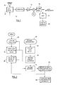
- the Figure 2 illustrates the principle of the invention, which consists in operating two types of analysis, namely a "long-term analysis” with channel scanning at regular intervals in the absence of any request for communication, and a “short analysis”. term “with channel scanning at the exact time a request for a call is made.
- step 22 The long-term analysis (step 22), the detailed principle of which will be explained with reference to Figure 5 is operated at regular intervals, for example every fifteen minutes.
- This analysis is performed by the base station because it takes advantage of the fact that there is available computing power and enough energy to perform the analysis of channels from this base station.
- the invention could also be implemented mutatis mutandis from the implant, although such an implementation is much more critical, particularly in terms of energy consumption.
- the base station Most of the time the base station is idle, with minimal power consumption. At regular intervals, it wakes up for an active period of a few seconds to analyze (step 22) the various available channels. The results of this analysis are stored and / or updated from previous results (step 24), then the base station returns to a dormant state for several minutes (step 26), waiting to be woken up for the next period of analysis or upon receipt of a specific interruption.
- the steps 22 and 24 of analysis and storage consist essentially of "listening" successively the different channels and to build a table with for each channel an indicator representative of the long-term availability of it.
- the whole of this table thus provides a global view of the "electromagnetic landscape" in the vicinity of the base station.
- the base station When a request for communication occurs (step 28), for example upon reception of a signal emitted by the implant, the base station will examine the different channels that may be used for the communication, in order to decide which channel will be used for signal exchange in accordance with the LBT ( Listen Before Talk ) step of the communication protocol prescribed by EN 301839.
- LBT Listen Before Talk
- the base station operates for this purpose a "short-term analysis" (step 30) of the same nature as the long-term analysis (step 22) that had been carried out previously in the absence of a request for communication.
- the results of this short-term analysis are stored (step 32) and combined (step 34) with the results obtained from the long-run analysis, so as to produce weighted results from which a channel will be selected and the communication established on this channel (step 36).
- the weighting parameters will be updated (step 38) at the end of the communication, to take account of the fact that it has been correctly carried out to completion or, on the contrary, had to be interrupted because too many transmission errors.
- the Figure 3 illustrates how the short-term or long-term analyzes of steps 22 and 30 of the Figure 2 .
- the level of the received signal is sampled (step 42), this level being conventionally designated RSSI ( Received Signal Strength Indicator ).
- RSSI Received Signal Strength Indicator
- the RSSI is then compared with a relatively low threshold (step 44), so as to determine if the signal received in reception is sufficiently low to be considered as background noise.
- a background noise level is calculated from the RSSI (step 46), giving a NoiseFloor value representative of this background noise level.
- the received signal is subjected to a low frequency filtering (step 48) to deliver an RSSI_BF indicator representative of the RSSI level out of background noise.
- the computation at this step 48 is similar to that of block 46, except that here the window is chosen so as not to filter the signal too much to extract the trend (one approaches the frequency of Shannon without realizing it, to be consistent with the modulating frequency).
- the signal is also applied to a peak detection stage (step 50) making it possible to detect a peak level appearing in the channel, even temporarily, in order to take into account in particular a troll effect representative of a saturation.
- the peak detection of the block 50 delivers an RSSI_Peak indicator representative of the energy of the eventual peak.
- RSSI_Peak >RSSI_BF> NoiseFloor.
- NoiseFloor The three parameters NoiseFloor, RSSI_BF and RSSI_ Peak are then combined (step 52) so as to operate a classification making it possible to discriminate the type of signal picked up in reception: background noise only, pure carrier, modulated carrier (with different types of modulation) etc.
- the received raw signal is represented, which in this example is an amplitude modulated signal in the form of a succession of slots.
- an interval M ⁇ ⁇ for example an interval of ⁇ 3 dB, has been defined around the level M.
- NoiseFloor which represents the overall background noise of the electronic circuits plus the ambient electromagnetic background noise, must not vary abruptly. A sudden variation would come from a non-physical event, for example due to a deterioration of the electronics, to problems related to the installation or degradation of the end-of-life product for example.
- the analysis of the variations of this value NoiseFloor can thus make it possible to generate possible alerts.
- RSSI_Peak RSSI_BF
- FSK Frequency Shift Keying
- the result is an indicator representative of the availability of the channel, defined for example in the form of a percentage or a confidence rate, in the short term or in the long term depending on when the analysis was made.
- the Figure 5 illustrates an example of various signals measured over ten channels ch0 to ch9.
- the long-term and short-term analyzes allow, for each of the channels ch0 to ch9 , to analyze the noise, the average RSSI, and to establish a confidence index, respectively in the long term and in the short term.
- N 24.
Abstract
Description
L'invention concerne les "dispositifs médicaux actifs" tels que définis par la directive 93/42/CE du 14 juin 1993 du Conseil des communautés européennes, et notamment les implants de type "dispositifs médicaux implantables actifs" tels que définis par la directive du Conseil 90/385/CEE du 20 juin 1990.The invention relates to "active medical devices" as defined by Directive 93/42 / EC of 14 June 1993 of the Council of the European Communities, and in particular implants of the "active implantable medical devices" type as defined by the Council 90/385 / EEC of 20 June 1990.
Cette définition inclut en particulier les appareils chargés de surveiller l'activité cardiaque et de générer des impulsions de stimulation, de resynchronisation, de défibrillation et/ou de cardioversion en cas de trouble du rythme détecté par l'appareil. Elle inclut aussi les appareils neurologiques, les pompes de diffusion de substances médicales, les implants cochléaires, les capteurs biologiques implantés, etc., ainsi que les dispositifs de mesure de pH ou encore d'impédance intracorporelle (telle que mesure d'impédance transpulmonaire ou d'impédance intracardiaque). On notera également que, si l'invention s'applique de manière particulièrement avantageuse aux appareils implantés tels que stimulateurs, cardioverteurs ou défibrillateurs, elle peut tout aussi bien être mise en oeuvre avec des dispositifs médicaux non implantés, par exemple des enregistreurs de données comme les appareils Holter externes destinés à la surveillance et à l'enregistrement en ambulatoire de certains paramètres physiologiques tels que par exemple l'activité cardiaque.This definition includes in particular the devices responsible for monitoring cardiac activity and generating pacing, resynchronization, defibrillation and / or cardioversion pulses in the event of arrhythmia detected by the device. It also includes neurological devices, medical substance delivery pumps, cochlear implants, implanted biological sensors, etc., as well as devices for measuring pH or intracorporeal impedance (such as trans-pulmonary impedance measurement or intracardiac impedance). It will also be noted that, while the invention applies particularly advantageously to implanted devices such as pacemakers, cardiovers or defibrillators, it can equally well be implemented with non-implanted medical devices, for example data loggers such as external Holter devices for ambulatory monitoring and recording of certain physiological parameters such as, for example, cardiac activity.
La plupart des dispositifs médicaux actifs sont conçus pour permettre un échange de données avec un "programmateur", qui est un appareil externe permettant de vérifier le paramétrage du dispositif, de lire des informations enregistrées par celui-ci ou d'y inscrire des informations, ou encore de mettre à jour le logiciel interne de pilotage du dispositif.Most active medical devices are designed to allow a data exchange with a "programmer", which is an external device for verifying the setting of the device, read information recorded by it or to enter information, or update the internal software for controlling the device.
Cet échange de données entre le dispositif médical et le programmateur est effectué par télémétrie, c'est-à-dire par une technique de transmission à distance d'informations, sans contact galvanique.This exchange of data between the medical device and the programmer is performed by telemetry, that is to say by a technique of remote transmission of information, without galvanic contact.
Jusqu'à présent, la télémétrie était le plus souvent opérée par couplage inductif entre des bobines du dispositif implanté et du programmateur, technique connue sous le nom de "procédé par induction". Cette technique présente cependant l'inconvénient, en raison de la très faible portée d'un tel couplage, de nécessiter l'utilisation d'une "tête de télémétrie" reliée au programmateur et contenant une bobine qu'un opérateur place au voisinage du site où est implanté le dispositif.Until now, telemetry was most often performed by inductive coupling between coils of the implanted device and the programmer, a technique known as the "induction method". However, this technique has the disadvantage, because of the very short range of such a coupling, to require the use of a "telemetry head" connected to the programmer and containing a coil that an operator places in the vicinity of the site where the device is implanted.
Il a été récemment proposé de mettre en oeuvre une autre technique de couplage non galvanique, utilisant les deux composantes d'une onde électromagnétique produite par des circuits émetteurs/récepteurs opérant dans le domaine des radiofréquences (RF), typiquement des fréquences de l'ordre de plusieurs centaines de mégahertz.It has recently been proposed to implement another non-galvanic coupling technique, using the two components of an electromagnetic wave produced by transmitter / receiver circuits operating in the field of radio frequencies (RF), typically frequencies of the order several hundred megahertz.
Cette technique, dite de "télémétrie RF" permet de programmer ou interroger des implants à des distances supérieures à 3 m, et autorise donc l'échange d'informations sans manipulation d'une tête de télémétrie, voire même sans intervention d'un opérateur externe.This technique, called "RF telemetry" allows programming or interrogating implants at distances greater than 3 m, and therefore allows the exchange of information without manipulation of a telemetry head, or even without the intervention of an operator external.
Un dispositif médical actif comprenant de tels moyens de télémétrie RF est par exemple décrit dans le
Le protocole de communication entre le dispositif actif (généralement un implant) et la station de base (programmateur du dispositif de "home monitor") est notamment régi par la norme EN 301839 "Compatibilité électromagnétique et spectre radioélectrique (ERM) - Dispositifs à courte portée (SRD) - Implants médicaux actifs de puissance ultra basse (ULP-AMI) et périphériques (ULP-AMI-P) fonctionnant dans la plage de fréquences de 402 MHz à 405 MHz". On notera toutefois que l'invention n'est pas limitée à une utilisation dans la bande 402-405 MHz, dite bande MICS (Medical Implants Communication Systems), mais qu'elle est applicable de façon générale à toutes les bandes susceptibles d'être utilisées pour de la télémétrie RF, notamment les bandes banalisées publiques ISM (Industriel, Scientifique et Médical) 863-870 MHz, 902-928 MHz et 2,4 GHz utilisées par les dispositifs médicaux.The communication protocol between the active device (usually an implant) and the base station (programmer of the "home monitor" device) is in particular governed by the EN 301839 standard "Electromagnetic compatibility and Radio spectrum Matters (ERM) - Short-range devices (SRD) - Ultra-low power (ULP-AMI) and peripheral (ULP-AMI-P) active medical implants operating in the 402 MHz to 405 MHz "frequency range. Note however that the invention is not limited to use in the band 402-405 MHz, called MICS band (Medical Implants Communication Systems), but that it is applicable in a general manner to all bands likely to be used for RF telemetry, including the publicly available ISM ( Industrial, Scientific and Medical ) 863-870 MHz, 902-928 MHz and 2.4 GHz publicized bands used by medical devices.
Par ailleurs, les appareils médicaux dotés de fonctions de télémétrie RF sont tous des appareils multicanaux, c'est-à-dire utilisant plusieurs fréquences situées dans une même bande (certains appareils pouvant être en outre multibande, mais il s'agit là d'un aspect qui ne concerne pas l'invention).Furthermore, medical devices with RF telemetry functions are all multichannel devices, that is to say using several frequencies located in the same band (some devices can be multiband in addition, but this is an aspect which does not relate to the invention).
De ce fait, préalablement à l'établissement d'une communication entre l'implant et la station de base, il est nécessaire de sélectionner un canal (c'est-à-dire une fréquence sur laquelle la communication sera opérée) parmi tous les canaux susceptibles d'être utilisés dans la bande considérée.Therefore, prior to the establishment of a communication between the implant and the base station, it is necessary to select a channel (that is to say a frequency on which the communication will be operated) among all channels likely to be used in the band under consideration.
Cette étape est importante, car il est indispensable de choisir un canal peu bruité, sur lequel on est pratiquement sûr que la communication pourra être conduite jusqu'à son terme sans être interrompue.This step is important because it is essential to choose a low noise channel, which is almost certain that the communication can be completed without interruption.
En effet, à la différence des techniques par induction qui présentent une bonne immunité aux parasites, la télémétrie RF est sujette à de nombreuses perturbations par l'environnement électromagnétique, notamment les signaux de radio, de télévision et de téléphonie mobile, sans compter les nombreux parasites industriels susceptibles d'être produits dans l'environnement immédiat du porteur de l'implant. L'implant qui veut communiquer sur un canal RF peut également se trouver en conflit avec d'autres dispositifs en train de communiquer situés à proximité qui, eux aussi, occupent des canaux de télémétrie RF. Toutes ces perturbations sont susceptibles de produire des interférences et de perturber la transmission des données.Indeed, unlike inductive techniques which have good immunity to parasites, RF telemetry is subject to many disturbances by the electromagnetic environment, including radio, television and mobile telephony signals, not to mention the many industrial pests likely to be produced in the immediate environment of the implant wearer. The implant that wants to communicate on an RF channel may also be in conflict with other nearby communicating devices that also occupy RF telemetry channels. All of these disturbances are likely to cause interference and disrupt data transmission.
Si l'on a sélectionné un canal trop bruité, la communication sera sujette à de nombreuses erreurs de transmission, conduisant à l'abandon du processus et à la recherche d'un nouveau canal. Il sera de ce fait nécessaire de réitérer complètement le processus de communication, et on aura dépensé de l'énergie pour une communication qui n'a pas abouti, donc pour rien.If you have selected a channel that is too noisy, the communication will be subject to many transmission errors, leading to the process being abandoned and the search for a new channel. It will be necessary to completely reiterate the process of communication, and we will have spent energy for a communication that has not succeeded, so for nothing.
Or la télémétrie RF implique une dépense énergétique relativement importante, tout au moins à l'échelle d'un implant dont la durée de vie est un paramètre extrêmement critique, de sorte que la multiplication des communications interrompues pourra avoir à terme une incidence non négligeable sur l'autonomie de l'implant.However, RF telemetry involves a relatively high energy expenditure, at least at the scale of an implant whose life time is an extremely critical parameter, so that the multiplication of interrupted communications may eventually have a significant impact on the autonomy of the implant.
Pour sélectionner un canal, on procède généralement par une scrutation préalable consistant à "écouter" successivement les différents canaux susceptibles d'être utilisés pour l'émission, avant de choisir l'un d'entre eux pour commencer à émettre un signal.To select a channel, it is generally done by a preliminary scan consisting of "listening" successively the different channels that can be used for transmission, before choosing one of them to start transmitting a signal.
Le
La technique décrite par ce document présente deux inconvénients principaux.The technique described by this document has two main disadvantages.
En premier lieu, du fait du critère d'analyse choisi, tout signal présent dans le canal est considéré comme du bruit. En d'autres termes, l'analyse ne fait aucune distinction entre du bruit de fond (c'est-à-dire du "vrai" bruit) et la présence d'un signal utile du fait d'une communication en cours sur ce canal : cette dernière est assimilé par le dispositif à du bruit, alors que cette émission peut très bien avoir lieu sur un canal de bonne qualité du point de vue du rapport signal/bruit. En d'autres termes, le dispositif peut très bien exclure un canal peu bruité, du seul fait que ce canal se trouve occupé à l'instant de la scrutation.In the first place, because of the analysis criterion chosen, any signal present in the channel is considered as noise. In other words, the analysis makes no distinction between background noise (ie "true" noise) and the presence of a useful signal due to a communication in progress on that background. channel: the latter is assimilated by the device to noise, while this emission can very well take place on a good quality channel from the point of view of the signal / noise ratio. In other words, the device can very well exclude a low noise channel, just because this channel is busy at the time of scanning.
En second lieu, l'analyse du seul niveau moyen de signal sur un canal au moment de la scrutation ne garantit pas que le canal sera effectivement libre au moment où l'on souhaitera commencer à émettre sur ce canal. Le risque évoqué plus haut subsiste, à savoir le risque d'une impossibilité d'établir la communication et la nécessité de passer à un autre canal en réitérant le processus, avec pour conséquence une inutile dépense d'énergie.Secondly, the analysis of the only average level of signal on a channel at the time of the scan does not guarantee that the channel will actually be free when it is desired to start transmitting on that channel. The risk mentioned above remains, namely the risk of an impossibility to establish communication and the need to move to another channel by repeating the process, resulting in unnecessary energy expenditure.
On notera que ce risque est particulièrement aggravé dans un milieu hospitalier où peuvent être simultanément présents plusieurs dispositifs d'un même fabricant (donc utilisant les mêmes algorithmes de choix de canal). En effet, il peut se trouver que plusieurs appareils veuillent établir une communication RF à des instants relativement proches et, du fait de ce léger décalage temporel, un dispositif pourra considérer qu'un canal est libre, alors que l'autre commencera à émettre peu de temps après et rendra impossible la communication du premier, obligeant ce dernier à réitérer la scrutation pour rechercher un autre canal, etc. La présence dans un même site d'une pluralité de produits de même origine peut être donc une source imprévue de brouillage, nécessitant de prévoir des logiques de fonctionnement avec des boucles d'échappatoire assez complexes.It should be noted that this risk is particularly aggravated in a hospital environment where several devices of the same manufacturer can be simultaneously present (thus using the same algorithms of choice of channel). Indeed, it may be that several devices want to establish RF communication at relatively close times and, because of this slight time shift, one device may consider that one channel is free, while the other will start to transmit little after a while and make it impossible for the first to communicate, forcing the latter to repeat the search for another channel, etc. The presence in the same site of a plurality of products of the same origin can therefore be an unexpected source of interference, requiring the provision of operating logic with fairly complex loopholes.
Ce phénomène est en outre accru par l'occupation globale relativement élevée des différents canaux en milieu clinique, le problème de trouver un canal disponible se surajoutant à celui de trouver un canal peu parasité. Le
Il serait de ce fait souhaitable de disposer d'une technique de recherche et de sélection de canal qui permette de distinguer entre un canal occupé et un canal présentant un niveau significatif de bruit parasite manière à pouvoir identifier des canaux présentant un bon rapport signal/bruit, même si ceux-ci sont occupés, afin de pouvoir les utiliser ultérieurement lorsqu'il seront libres.It would therefore be desirable to have a channel search and selection technique that distinguishes between a busy channel and a channel with a significant level of spurious noise so as to be able to identify channels having a good signal-to-noise ratio. even if they are busy, so that they can be used later when they are free.
Le but de l'invention est de pallier les divers inconvénients exposés ci-dessus, en proposant une technique d'analyse et de sélection des canaux permettant de maximiser la probabilité d'établir une connexion sur ce canal et de poursuivre celle-ci jusqu'à son terme.The aim of the invention is to overcome the various disadvantages described above, by proposing a channel analysis and selection technique making it possible to maximize the probability of establishing a connection on this channel and to continue it until at its end.
En d'autres termes, le but de l'invention est de proposer une nouvelle technique de sélection non seulement d'un canal libre et peu bruité au moment de la scrutation, mais d'un canal qui ait des chances de rester libre au moment où le dispositif tentera d'établir la communication.In other words, the object of the invention is to propose a new selection technique not only of a free channel and little noisy at the time of the scan, but of a channel that is likely to remain free at the moment where the device will attempt to establish communication.
Il s'agit ainsi de maximiser la probabilité d'établir et de mener à son terme une communication sur ce canal dès la première tentative, en diminuant par conséquent la quantité d'énergie globale nécessaire pour transférer des informations entre l'implant et la station de base, avec pour conséquence un impact minimum de la télémétrie RF sur la durée de vie de cet implant.This is to maximize the probability of establishing and completing a communication on this channel at the first attempt, thereby decreasing the amount of overall energy needed to transfer information between the implant and the station basic, resulting in a minimum impact of RF telemetry on the life of this implant.
Un autre but de l'invention est de proposer une telle technique qui n'exige que des ressources modestes en termes de puissance de calcul, ne faisant intervenir que des algorithmes simples, ou même des logiques susceptibles d'être implémentées sous forme matérielle à partir de comparateurs et de circuits à seuil, d'une façon particulièrement avantageuse en ce qui concerne l'implant.Another object of the invention is to propose such a technique that requires only modest resources in terms of computing power, involving only simple algorithms, or even logic that can be implemented in hardware form from comparators and threshold circuits, in a particularly advantageous manner with respect to the implant.
L'invention propose à cet effet un procédé de recherche et de sélection d'un canal de communication préalablement à l'établissement d'une liaison de télémétrie RF avec un dispositif distant, ce procédé étant du type général connu d'après le
Le procédé de l'invention est caractérisé en ce que : ledit premier indicateur est un indicateur long terme représentatif de la disponibilité à long terme du canal, et ledit second indicateur est un indicateur court terme représentatif de la disponibilité à court terme du canal ; ladite seconde analyse est suivie d'une étape de pondération de l'indicateur court terme par l'indicateur long terme mémorisé, pour donner un indicateur court terme pondéré ; et ladite sélection est opérée sur la base de l'indicateur court terme pondéré.The method of the invention is characterized in that: said first indicator is a long-term indicator representative of the long-term availability of the channel, and said second indicator is a short-term indicator representative of the short-term availability of the channel; said second analysis is followed by a weighting step of the short-term indicator by the stored long-term indicator, to give a weighted short-term indicator; and said selection is made on the basis of the weighted short-term indicator.
La première ou la seconde analyse peuvent en particulier comprendre une étape de comparaison du niveau du signal de chaque canal à un seuil prédéterminé de niveau de bruit de base.The first or the second analysis may in particular comprise a step of comparing the signal level of each channel with a predetermined threshold of basic noise level.
Ceci permet notamment, pour chaque canal dont le niveau de signal est supérieur au niveau de bruit de base, une étape de discrimination de type de signal, apte à différencier un signal utile de trame de données et un signal parasite.This allows, in particular, for each channel whose signal level is higher than the basic noise level, a signal type discrimination step, capable of differentiating a useful data frame signal and a spurious signal.
Cette discrimination peut en particulier comprendre l'application au signal d'un filtrage passe-bas sur une fenêtre temporelle de durée prédéterminée, et la comparaison entre le signal filtré et le signal non filtré, pour donner un premier indicateur de type de signal, et/ou la détection d'un niveau de pic du signal, et la comparaison entre le niveau de pic du signal et le signal filtré, pour donner un deuxième indicateur de type de signal.This discrimination may in particular comprise the application to the signal of a low-pass filtering over a time window of predetermined duration, and the comparison between the filtered signal and the unfiltered signal, to give a first signal type indicator, and / or detecting a peak level of the signal, and comparing the peak level of the signal with the filtered signal, to provide a second signal type indicator.
On va maintenant décrire un exemple de mise en oeuvre de l'invention, en référence aux dessins annexés où les mêmes références numériques désignent d'une figure à l'autre des éléments identiques ou fonctionnellement semblables.
- La
Figure 1 est une vue schématique des différents blocs fonctionnels du circuit de réception d'un dispositif médical mettant en oeuvre l'invention. - La
Figure 2 est un organigramme général expliquant les différentes étapes de l'analyse à long terme, en dehors des périodes de communication, et à court terme, en cas de demande de communication, et la combinaison des résultats obtenus pour la détermination des critères de sélection du canal. - La
Figure 3 est un organigramme illustrant de manière plus précise la manière dont sont opérée les analyses à long terme et à court terme de l'organigramme de laFigure 2 . - Les
Figures 4a et 4b illustrent des exemples de signaux analysés et discriminés par le classifieur de l'invention. - La
Figure 5 est un exemple de signaux qu'il est possible de mesurer sur dix canaux successifs, montrant divers niveaux de signal et divers types de brouillage. - La
Figure 6 illustre de façon schématique la manière dont l'invention est mise en oeuvre, avec les phases successives d'analyse à long terme, d'analyse à court terme, et de sélection du canal en fonction du résultat de ces deux analyses.
- The
Figure 1 is a schematic view of the different functional blocks of the receiving circuit of a medical device embodying the invention. - The
Figure 2 is a general flowchart explaining the different stages of the long-term analysis, outside the communication periods, and in the short term, in case of communication request, and the combination of the results obtained for the determination of the channel selection criteria . - The
Figure 3 is a flowchart illustrating more precisely how the long-term and short-term analyzes of the organization's flow chart are carried out.Figure 2 . - The
Figures 4a and 4b illustrate examples of signals analyzed and discriminated by the classifier of the invention. - The
Figure 5 is an example of signals that can be measured over ten successive channels, showing various signal levels and types of interference. - The
Figure 6 illustrates schematically the manner in which the invention is implemented, with the successive phases of long-term analysis, short-term analysis, and selection of the channel according to the result of these two analyzes.
Sur la
Les signaux captés par une antenne RF 10 sont appliqués à un étage atténuateur 12 commandé par un signal TX. Concrètement, au cours d'une communication déjà établie, l'atténuateur 12 est en position "RX" de réception, c'est-à-dire d'atténuation minimale. En revanche, dans une phase préalable de scrutation des canaux, lorsque l'on n'a pas connaissance du niveau de signal pouvant être présent sur ce canal, l'atténuateur est basculé sur la position "TX" d'émission (et ceci bien que le dispositif continue à opérer en réception) de manière à éviter de saturer les étages situés en aval ; ce n'est que si l'on détecte un signal suffisamment faible que l'atténuateur 12 sera basculé sur la position "RX" pour bénéficier de la sensibilité maximale.The signals picked up by an
Le signal ainsi recueilli est appliqué ensuite à une série d'étages haute fréquence 14 comprenant un présélecteur (qui permet de ne garder que la bande de fréquences d'intérêt et permet de protéger le récepteur d'autres émissions RF, le media étant un media partagé), un amplificateur faible bruit LNA (pour augmenter le rapport signal/bruit), oscillateur local OL et mélangeur X, avec une architecture superhétérodyne classique de récepteur RF. Le signal à fréquence intermédiaire obtenu est appliqué à un filtre réjecteur 16 correspondant au canal sélectionné (pour ne garder que les signaux présents dans le canal d'intérêt), par exemple un filtre comprenant un résonateur à ondes acoustiques de volume BAW (Bulk Acoustic Waves) tel que celui décrit par exemple dans le
Le signal recueilli en sortie du filtre de canal 16, qui normalement est appliqué au circuit de démodulation dans le cadre d'une communication déjà établie, est ici utilisé pour détecter le niveau de signal après avoir été appliqué à un convertisseur analogique/numérique 18 et à une unité de traitement 20 dont on va décrire le fonctionnement détaillé en référence aux
La
L'analyse à long terme (étape 22), dont le principe détaillé sera exposé en référence à la
Cette analyse est effectuée par la station de base car on profite du fait que l'on dispose d'une puissance de calcul disponible et de suffisamment d'énergie pour effectuer l'analyse des canaux depuis cette station de base. Cela étant, l'invention pourrait être également mise en oeuvre mutatis mutandis à partir de l'implant, bien qu'une telle mise en oeuvre soit beaucoup plus critique notamment sur le plan de la consommation énergétique.This analysis is performed by the base station because it takes advantage of the fact that there is available computing power and enough energy to perform the analysis of channels from this base station. However, the invention could also be implemented mutatis mutandis from the implant, although such an implementation is much more critical, particularly in terms of energy consumption.
La majeure partie du temps la station de base est inactive, avec une consommation électrique minimale. À intervalles réguliers, elle se réveille pendant une période active de quelques secondes pour procéder à l'analyse (étape 22) des différents canaux disponibles. Les résultats de cette analyse sont mémorisés et/ou mis à jour par rapport aux résultats antérieurs (étape 24), puis la station de base retourne à un état dormant pendant plusieurs minutes (étape 26), en attendant d'être réveillée pour la prochaine période d'analyse ou sur réception d'une interruption spécifique.Most of the time the base station is idle, with minimal power consumption. At regular intervals, it wakes up for an active period of a few seconds to analyze (step 22) the various available channels. The results of this analysis are stored and / or updated from previous results (step 24), then the base station returns to a dormant state for several minutes (step 26), waiting to be woken up for the next period of analysis or upon receipt of a specific interruption.
Les étapes 22 et 24 d'analyse et de mémorisation, qui seront détaillées par la suite en référence à la
La station de base opère à cet effet une "analyse à court terme" (étape 30) de même nature que l'analyse à long terme (étape 22) qui avait été opérée auparavant en l'absence de demande de communication.The base station operates for this purpose a "short-term analysis" (step 30) of the same nature as the long-term analysis (step 22) that had been carried out previously in the absence of a request for communication.
De façon caractéristique de l'invention, les résultats de cette analyse à court terme sont mémorisés (étape 32) et combinés (étape 34) aux résultats obtenus de l'analyse à long terme, de manière à produire des résultats pondérés à partir desquels un canal sera sélectionné et la communication établie sur ce canal (étape 36).Characteristically, the results of this short-term analysis are stored (step 32) and combined (step 34) with the results obtained from the long-run analysis, so as to produce weighted results from which a channel will be selected and the communication established on this channel (step 36).
Les paramètres de pondération seront mis à jour (étape 38) à l'issue de la communication, pour tenir compte du fait que celle-ci s'est déroulée correctement jusqu'à son terme ou, au contraire, a dû être interrompue en raison d'erreurs de transmission trop nombreuses.The weighting parameters will be updated (step 38) at the end of the communication, to take account of the fact that it has been correctly carried out to completion or, on the contrary, had to be interrupted because too many transmission errors.
La
Pour chaque canal i sélectionné lors de la scrutation (étape 40), le niveau du signal capté en réception est échantillonné (étape 42), ce niveau étant désigné conventionnellement RSSI (Received Signal Strength Indicator). Le RSSI est ensuite comparé à un seuil relativement bas (étape 44), de manière à déterminer si le signal capté en réception est suffisamment faible pour être considéré comme du bruit de fond.For each channel i selected during the scan (step 40), the level of the received signal is sampled (step 42), this level being conventionally designated RSSI ( Received Signal Strength Indicator ). The RSSI is then compared with a relatively low threshold (step 44), so as to determine if the signal received in reception is sufficiently low to be considered as background noise.
Dans l'affirmative, un niveau de bruit de fond est calculé à partir du RSSI (étape 46), donnant une valeur NoiseFloor représentative de ce niveau de bruit de fond. On peut notamment calculer une moyenne glissante à grande fenêtre, permettant de filtrer au maximum le signal afin d'en évaluer le bruit de fond. Un nouvel échantillon ne sera introduit dans cette moyenne que s'il apparait comme étant du signal, c'est-à-dire s'il présente une amplitude supérieure à l'échantillon de bruit de fond précédent, selon les relations : 

S'il ressort du test 44 que le signal capté en réception que le signal capté en réception n'est vraisemblablement pas constitué d'un simple bruit de fond, il ne doit pas figurer dans le calcul du niveau de NoiseFloor (ce qui reviendrait à augmenter artificiellement le bruit de fond, de manière non réaliste).If it emerges from the
Dans ce dernier cas, le signal reçu est soumis à un filtrage basse fréquence (étape 48) pour délivrer un indicateur RSSI_BF représentatif du niveau du RSSI hors bruit de fond. Le calcul à cette étape 48 est semblable à celui du bloc 46, sauf qu'ici la fenêtre est choisie pour ne pas trop filtrer le signal pour en extraire la tendance (on s'approche de la fréquence de Shannon sans la réaliser, pour être cohérent avec la fréquence modulante). Le signal est également appliqué à un étage de détection de pic (étape 50) permettant de détecter un pic de niveau apparaissant dans le canal, même de façon temporaire, pour pouvoir prendre en compte notamment un effet de traîne représentatif d'une saturation.In the latter case, the received signal is subjected to a low frequency filtering (step 48) to deliver an RSSI_BF indicator representative of the RSSI level out of background noise. The computation at this
Pour détecter ce pic, on procède de la manière suivante : si le nouvel échantillon est supérieur au précédent, alors on conserve la valeur, dans le cas contraire on diminue simplement la valeur maximale mémorisée. Ceci permet de garder une trace de l'existence de ce pic et, en mesurant le temps pendant lequel ce pic est supérieur à la moyenne du bloc 50, on peut en estimer l'amplitude crête et mesurer des fréquences de répétition afin de savoir si l'on est en présence d'un phénomène périodique ou non.To detect this peak, proceed as follows: if the new sample is greater than the previous one, then the value is retained, otherwise the maximum value memorized is simply decreased. This makes it possible to keep track of the existence of this peak and, by measuring the time during which this peak is greater than the average of the
La détection de pic du bloc 50 délivre un indicateur RSSI_Peak représentatif de l'énergie du pic éventuel. De façon générale, on aura RSSI_Peak > RSSI_BF> NoiseFloor. The peak detection of the
Les trois paramètres NoiseFloor, RSSI_BF et RSSI_ Peak sont ensuite combinés (étape 52) de manière à opérer une classification permettant de discriminer le type de signal capté en réception : bruit de fond uniquement, porteuse pure, porteuse modulée (avec différents types de modulation), etc.The three parameters NoiseFloor, RSSI_BF and RSSI_ Peak are then combined (step 52) so as to operate a classification making it possible to discriminate the type of signal picked up in reception: background noise only, pure carrier, modulated carrier (with different types of modulation) etc.
Cette discrimination sera expliquée en référence aux
Sur la
Le classifieur considèrera que le signal capté est effectivement un signal modulé en amplitude si les conditions suivantes sont vérifiées :
- le niveau maximum MAX du signal est supérieur d'au moins 3dB (par exemple) au niveau NoiseFloordu bruit de fond ;
- le nombre d'échantillons du signal capté numérisé qui se situent au niveau maximum MAX correspond (à un facteur d'incertitude près) au nombre d'échantillons qui se situent au niveau minimum MIN, ce qui revient à dire que les échantillons de signal sont équirépartis entre le maximum et le minimum du signal ; et
- la moyenne des niveaux des échantillons est située dans l'intervalle M ± Δ autour du niveau M = (MAX+MIN)/2.
- the MAX maximum level of the signal is at least 3dB (for example) higher than NoiseFloordu noise level;
- the number of samples of the digitized captured signal that are at the MAX maximum level corresponds (within a factor of uncertainty) to the number of samples that are at the MIN minimum level, which is to say that the signal samples are equidistributed between the maximum and the minimum of the signal; and
- the average of the sample levels is in the range M ± Δ around the level M = (MAX + MIN) / 2.
Sur la
Le classifieur considèrera que le signal capté est effectivement un tel signal si les conditions suivantes sont vérifiées :
- le niveau maximum MAX du signal est supérieur d'au moins 3dB (par exemple) au niveau NoiseFloordu bruit de fond ;
- le nombre d'échantillons du signal capté numérisé qui se situent au niveau maximum MAX correspond (à un facteur d'incertitude près) au nombre d'échantillons qui se situent au niveau minimum MIN, ce qui revient à dire que les échantillons de signal sont équirépartis entre le maximum et le minimum du signal ;
- la différence entre les niveaux MAX et MIN du signal est inférieure à un seuil limite, par exemple cette différence est inférieure à 3 dB.
- the MAX maximum level of the signal is at least 3dB (for example) higher than NoiseFloordu noise level;
- the number of samples of the digitized captured signal that are at the MAX maximum level corresponds (within a factor of uncertainty) to the number of samples that are at the MIN minimum level, which is to say that the signal samples are equidistributed between the maximum and the minimum of the signal;
- the difference between the MAX and MIN levels of the signal is less than a threshold limit, for example this difference is less than 3 dB.
Une discrimination supplémentaire peut être opérée pour voir si le signal est en cours d'apparition (signal S3) ou non (signal S2), en mesurant le "taux de remplissage" qui représente le nombre d'échantillons dont le niveau est proche du maximum par rapport au nombre total d'échantillons. Une fois que l'analyse du signal présent sur le canal i a été opérée de cette manière, la même analyse est ensuite effectuée pour le canal suivant i+1 (étape 54), et ce jusqu'à ce que tous les canaux aient été explorés.Additional discrimination can be made to see if the signal is being displayed (signal S 3 ) or not (signal S 2 ), by measuring the "filling ratio" which represents the number of samples whose level is close of the maximum relative to the total number of samples. Once the analysis of the signal present on the channel i has been operated in this way, the same analysis is then carried out for the next channel i +1 (step 54), until all the channels have been explored.
Dans un fonctionnement normal du dispositif, le paramètre NoiseFloor, qui représente le bruit de fond global des circuits électroniques plus le bruit de fond électromagnétique ambiant, ne doit pas varier brutalement. Une variation brutale proviendrait d'un événement non physique, par exemple dû à une détérioration de l'électronique, à des problèmes liés à l'installation ou à une dégradation du produit en fin de vie par exemple. L'analyse des variations de cette valeur NoiseFloor peut donc permettre de générer des alertes éventuelles.In normal operation of the device, the NoiseFloor parameter , which represents the overall background noise of the electronic circuits plus the ambient electromagnetic background noise, must not vary abruptly. A sudden variation would come from a non-physical event, for example due to a deterioration of the electronics, to problems related to the installation or degradation of the end-of-life product for example. The analysis of the variations of this value NoiseFloor can thus make it possible to generate possible alerts.
La comparaison des paramètres RSSI_Peak et RSSI_BF permet d'évaluer la durée moyenne des brouilleurs, afin par exemple de distinguer entre un simple pic ou bien une trame de signal, ou même pour identifier la nature de la modulation : par exemple si RSSI_Peak = RSSI_BF, on se trouve vraisemblablement en présence d'un signal modulé FSK (Frequency Shift Keying, modulation à saut de fréquences discrètes) tandis que si RSSI_Peak > RSSI_BF + Δ, on a vraisemblablement affaire à un signal OOK (On-Off Keying, modulation en tout-ou-rien), etc.The comparison of the parameters RSSI_Peak and RSSI_BF makes it possible to evaluate the average duration of the jammers, for example to distinguish between a simple peak or a signal frame, or even to identify the nature of the modulation: for example if RSSI_Peak = RSSI_BF, it is likely to be in the presence of a FSK ( Frequency Shift Keying) modulated signal , whereas if RSSI_Peak> RSSI_BF + Δ, it is likely to be an OOK signal ( On-Off Keying, modulation in all -or-nothing), etc.
On voit ainsi que par des comparaisons relativement simples, pouvant même être réalisées sous forme matérielle, il est possible de reconnaître certains types de brouilleurs dont les caractéristiques auront été identifiées ou apprises, et d'opérer la classification recherchée par un tri des paramètres mesurés.It can thus be seen that by relatively simple comparisons, which can even be carried out in material form, it is possible to recognize certain types of jammers whose characteristics have been identified or learned, and to effect the classification sought by a sorting of the measured parameters.
Le résultat est un indicateur représentatif de la disponibilité du canal, défini par exemple sous forme d'un pourcentage ou d'un taux de confiance, à court terme ou à long terme selon le moment auquel aura été opérée l'analyse.The result is an indicator representative of the availability of the channel, defined for example in the form of a percentage or a confidence rate, in the short term or in the long term depending on when the analysis was made.
La
La
- l'analyse à long terme (étape qui est en fait réitérée à intervalles réguliers pendant les périodes d'inactivité de la station de base) ;
- la demande de communication ;
- l'analyse à court terme des canaux ;
- la sélection du canal ; et
- l'établissement et la poursuite de la communication.
- long-term analysis (a step that is actually repeated at regular intervals during periods of inactivity of the base station);
- the request for communication;
- short-term channel analysis;
- channel selection; and
- establishing and continuing communication.
Les analyses à long terme et à court terme permettent, pour chacun des canaux ch0 à ch9, d'analyser le bruit, le RSSI moyen, et d'établir un indice de confiance, respectivement à long terme et à court terme.The long-term and short-term analyzes allow, for each of the channels ch0 to ch9 , to analyze the noise, the average RSSI, and to establish a confidence index, respectively in the long term and in the short term.
C'est la combinaison des indices de confiance à long terme (LT) et à court terme (CT), schématisée par les flèches référencées ICLT et ICCT, qui permettent de disposer d'un indice de confiance pondéré ICP à partir duquel sera sélectionné l'un des dix canaux.It is the combination of the long-term (LT) and short-term (CT) confidence indexes, schematized by the arrows referenced ICLT and ICCT, which make it possible to have an ICP weighted confidence index from which will be selected the one of the ten channels.
Cette combinaison peut être opéré par le biais d'une moyenne glissante, avec des fenêtres de longueurs différentes pour l'analyse court terme et pour l'analyse long terme. Ainsi, pour le canal chx d'indice x on aura respectivement : 

On peut avoir dans ce cas fenêtre_LT = N x fenêtre_CT. N permet alors d'ajuster directement le rapport entre les deux analyses. N peut être fixé arbitrairement comme étant le ratio temporel entre les deux. Par exemple, si l'analyse à court terme est faite une fois par jour alors que l'analyse à long terme est faite une fois par heure, on aura : N = 24.In this case, we can have window_LT = N x window_CT. N then makes it possible to directly adjust the ratio between the two analyzes. N can be arbitrarily set as the time ratio between the two. For example, if the short-term analysis is done once a day while the long-term analysis is done once an hour, we will have: N = 24.
Dans l'exemple illustré
Claims (5)
comprenant les étapes suivantes :
comprising the following steps:
Applications Claiming Priority (1)
| Application Number | Priority Date | Filing Date | Title |
|---|---|---|---|
| FR1053858 | 2010-05-19 |
Publications (2)
| Publication Number | Publication Date |
|---|---|
| EP2388043A1 true EP2388043A1 (en) | 2011-11-23 |
| EP2388043B1 EP2388043B1 (en) | 2016-03-23 |
Family
ID=43447017
Family Applications (1)
| Application Number | Title | Priority Date | Filing Date |
|---|---|---|---|
| EP11162935.8A Active EP2388043B1 (en) | 2010-05-19 | 2011-04-19 | Method for searching and selecting an RF telemetry channel to establish a link with an active medical device |
Country Status (2)
| Country | Link |
|---|---|
| US (2) | US8823547B2 (en) |
| EP (1) | EP2388043B1 (en) |
Cited By (1)
| Publication number | Priority date | Publication date | Assignee | Title |
|---|---|---|---|---|
| WO2019046133A1 (en) * | 2017-08-28 | 2019-03-07 | Advanced Bionics Ag | Systems and methods for facilitating alignment of cochlear implant system components |
Families Citing this family (3)
| Publication number | Priority date | Publication date | Assignee | Title |
|---|---|---|---|---|
| US8542646B1 (en) * | 2011-06-03 | 2013-09-24 | Olympus Corporation | Interference mitigation for network communications |
| WO2016099522A1 (en) * | 2014-12-18 | 2016-06-23 | Draeger Medical Systems, Inc. | Identification of patient-connected medical devices |
| EP3804145A4 (en) * | 2018-06-08 | 2022-01-12 | Nokia Technologies OY | Noise floor estimation for signal detection |
Citations (6)
| Publication number | Priority date | Publication date | Assignee | Title |
|---|---|---|---|---|
| US20020045920A1 (en) | 2000-08-26 | 2002-04-18 | Medtronic, Inc. | Implanted medical device telemetry using integrated thin film bulk acoustic resonator filtering |
| US6441747B1 (en) * | 2000-04-18 | 2002-08-27 | Motorola, Inc. | Wireless system protocol for telemetry monitoring |
| WO2007114743A1 (en) * | 2006-03-31 | 2007-10-11 | St. Jude Medical Ab | Received signal strength measurement compensation |
| EP1862191A1 (en) | 2006-12-20 | 2007-12-05 | HUANG, Hung-Chi | Safety syringe device |
| EP1862195A1 (en) | 2006-06-02 | 2007-12-05 | Ela Medical | Active medical device such as an active implant or programmer for such an implant, comprising RF telemetry means |
| US20080015655A1 (en) | 2006-07-12 | 2008-01-17 | Bange Joseph E | Implantable medical device telemetry with adaptive frequency hopping |
Family Cites Families (20)
| Publication number | Priority date | Publication date | Assignee | Title |
|---|---|---|---|---|
| US6556871B2 (en) * | 2001-01-04 | 2003-04-29 | Cardiac Pacemakers, Inc. | System and method for receiving telemetry data from an implantable medical device |
| US7280872B1 (en) * | 2003-10-16 | 2007-10-09 | Transoma Medical, Inc. | Wireless communication with implantable medical device |
| US20050208949A1 (en) * | 2004-02-12 | 2005-09-22 | Chiueh Tzi-Cker | Centralized channel assignment and routing algorithms for multi-channel wireless mesh networks |
| US7218969B2 (en) * | 2005-01-19 | 2007-05-15 | Cardiac Pacemakers, Inc. | Dynamic channel selection for RF telemetry with implantable device |
| US7664553B2 (en) * | 2005-04-27 | 2010-02-16 | Cardiac Pacemakers, Inc. | System and method for enabling communications with implantable medical devices |
| US7801620B2 (en) * | 2005-08-29 | 2010-09-21 | Cardiac Pacemakers, Inc. | RF telemetry link quality assessment system and method |
| US8065018B2 (en) * | 2005-09-12 | 2011-11-22 | Medtronic, Inc. | System and method for unscheduled wireless communication with a medical device |
| US7761146B2 (en) * | 2006-04-21 | 2010-07-20 | Medtronic, Inc. | Method and apparatus for detection of nervous system disorders |
| US20070249953A1 (en) * | 2006-04-21 | 2007-10-25 | Medtronic, Inc. | Method and apparatus for detection of nervous system disorders |
| US7761145B2 (en) * | 2006-04-21 | 2010-07-20 | Medtronic, Inc. | Method and apparatus for detection of nervous system disorders |
| US7623922B2 (en) * | 2006-07-12 | 2009-11-24 | Cardiac Pacemakers, Inc. | Implantable medical device telemetry with periodic frequency hopping |
| US7769456B2 (en) * | 2006-09-01 | 2010-08-03 | Cardiac Pacemakers, Inc. | Frequency-agile system for telemetry with implantable device |
| US7742822B2 (en) * | 2007-04-24 | 2010-06-22 | Medtronic, Inc. | Channel selection and mapping for medical device communication |
| US7957813B1 (en) * | 2007-05-08 | 2011-06-07 | Pacesetter, Inc. | Adaptive staged wake-up for implantable medical device communication |
| US7957451B1 (en) * | 2008-03-06 | 2011-06-07 | Rockwell Collins, Inc. | Cognitive spectral sensor-based PN hopping/spreading sequence generator |
| US8059628B2 (en) * | 2008-04-07 | 2011-11-15 | Medtronic, Inc. | Low power multiple channel mixing architecture for detecting wake-up signals and related falsing protection algorithm |
| US8170515B2 (en) * | 2008-05-21 | 2012-05-01 | Medtronic, Inc. | Method and apparatus for the phased detection of a signal including a frequency deviation detection phase |
| US8554333B2 (en) * | 2008-07-24 | 2013-10-08 | Pacesetter, Inc. | Adaptable communication sensitivity for an implantable medical device |
| US8805528B2 (en) * | 2009-03-31 | 2014-08-12 | Medtronic, Inc. | Channel assessment and selection for wireless communication between medical devices |
| US8023899B2 (en) * | 2009-04-30 | 2011-09-20 | Bandspeed, Inc. | Approach for selecting communications channels in communication systems to avoid interference |
-
2011
- 2011-04-19 EP EP11162935.8A patent/EP2388043B1/en active Active
- 2011-05-19 US US13/111,854 patent/US8823547B2/en active Active
-
2014
- 2014-08-29 US US14/473,739 patent/US9532365B2/en active Active
Patent Citations (7)
| Publication number | Priority date | Publication date | Assignee | Title |
|---|---|---|---|---|
| US6441747B1 (en) * | 2000-04-18 | 2002-08-27 | Motorola, Inc. | Wireless system protocol for telemetry monitoring |
| US20020045920A1 (en) | 2000-08-26 | 2002-04-18 | Medtronic, Inc. | Implanted medical device telemetry using integrated thin film bulk acoustic resonator filtering |
| US6868288B2 (en) | 2000-08-26 | 2005-03-15 | Medtronic, Inc. | Implanted medical device telemetry using integrated thin film bulk acoustic resonator filtering |
| WO2007114743A1 (en) * | 2006-03-31 | 2007-10-11 | St. Jude Medical Ab | Received signal strength measurement compensation |
| EP1862195A1 (en) | 2006-06-02 | 2007-12-05 | Ela Medical | Active medical device such as an active implant or programmer for such an implant, comprising RF telemetry means |
| US20080015655A1 (en) | 2006-07-12 | 2008-01-17 | Bange Joseph E | Implantable medical device telemetry with adaptive frequency hopping |
| EP1862191A1 (en) | 2006-12-20 | 2007-12-05 | HUANG, Hung-Chi | Safety syringe device |
Cited By (4)
| Publication number | Priority date | Publication date | Assignee | Title |
|---|---|---|---|---|
| WO2019046133A1 (en) * | 2017-08-28 | 2019-03-07 | Advanced Bionics Ag | Systems and methods for facilitating alignment of cochlear implant system components |
| WO2019045681A1 (en) * | 2017-08-28 | 2019-03-07 | Advanced Bionics Ag | Systems for facilitating optimal alignment of cochlear implant system components |
| CN111050844A (en) * | 2017-08-28 | 2020-04-21 | 领先仿生公司 | Systems and methods for facilitating alignment of cochlear implant system components |
| CN111050844B (en) * | 2017-08-28 | 2024-03-08 | 领先仿生公司 | Systems and methods for facilitating alignment of cochlear implant system components |
Also Published As
| Publication number | Publication date |
|---|---|
| US9532365B2 (en) | 2016-12-27 |
| US20140370926A1 (en) | 2014-12-18 |
| US20110285545A1 (en) | 2011-11-24 |
| EP2388043B1 (en) | 2016-03-23 |
| US8823547B2 (en) | 2014-09-02 |
Similar Documents
| Publication | Publication Date | Title |
|---|---|---|
| EP2583484B1 (en) | Method of securing a wireless communication, receiver device and communication system implementing this method | |
| EP2388043B1 (en) | Method for searching and selecting an RF telemetry channel to establish a link with an active medical device | |
| EP1244049B1 (en) | Wireless communication system between a plurality of transceivers and transponders | |
| EP2541782B1 (en) | RF telemetry receiver circuit for active medical implant | |
| EP1459240A1 (en) | Non-contact integrated circuit reader comprising a low power consumption active standby mode | |
| FR2878964A1 (en) | METHOD FOR LOCATING A TRANSMITTING AND RECEIVING DEVICE | |
| FR2683326A1 (en) | Method of interrogating a radar transponder, and transponder for implementing the method | |
| CA2439563A1 (en) | Device and method for the suppression of pulsed wireless signals | |
| WO2021254936A1 (en) | Method for activating a function of a vehicle by ultra high frequency with an item of portable user equipment and device for activating an associated function | |
| EP2579486B1 (en) | Optimised transmission method by RF telemetry between an active implantable medical device and a remote external receiver | |
| EP0933885A1 (en) | Method for cyclic detection in polarisation diversity of digital cyclostationary signals | |
| EP3157181B1 (en) | Ultra wideband signal detection | |
| EP2761531A1 (en) | Configuring the type of modulation for a near-field communication router | |
| EP0854582B1 (en) | Click noise reduction method in a data transmission system | |
| EP3335438B1 (en) | Method of analysis of resources frequency and selecting pulse frequency in a wireless communication system | |
| FR2818784A1 (en) | RADIO FREQUENCY RECEIVER FOR COUNTERLIGHT OF COUNTERS AND METHOD OF TELERELEVE OF COUNTERS COMPRISING SUCH A RECEIVER | |
| EP2920604B1 (en) | System and method for radio-tagging radio transmitters | |
| EP1453217B1 (en) | Method for the attenuation of the influence of interferences produced by radio burst transmision systems on UWB communications | |
| FR3111759A1 (en) | PROCESS FOR RECEIVING DATA IN A RADIO FREQUENCY TRANSMISSION | |
| EP1507347B1 (en) | Apparatus for determining SAR (Specific Absorption Rate) variations in a mobile communication terminal | |
| WO2016096823A1 (en) | Test method implemented by an apparatus comprising at least two radio communication devices | |
| EP1962678A1 (en) | Device for transmitting physiological signals of a wearer | |
| EP3722989A1 (en) | Method for managing the contents of a display case for presenting products provided with rfid tags | |
| EP2728909A1 (en) | Method for obtaining digitised samples of radio signals, method for processing a sample search query, method for processing radio signals, related devices and equipment | |
| EP2749898B1 (en) | Method for optimizing monitoring or polling of signals by a sensor |
Legal Events
| Date | Code | Title | Description |
|---|---|---|---|
| AK | Designated contracting states |
Kind code of ref document: A1 Designated state(s): AL AT BE BG CH CY CZ DE DK EE ES FI FR GB GR HR HU IE IS IT LI LT LU LV MC MK MT NL NO PL PT RO RS SE SI SK SM TR |
|
| AX | Request for extension of the european patent |
Extension state: BA ME |
|
| PUAI | Public reference made under article 153(3) epc to a published international application that has entered the european phase |
Free format text: ORIGINAL CODE: 0009012 |
|
| 17P | Request for examination filed |
Effective date: 20120227 |
|
| 17Q | First examination report despatched |
Effective date: 20120703 |
|
| REG | Reference to a national code |
Ref country code: DE Ref legal event code: R079 Ref document number: 602011024231 Country of ref document: DE Free format text: PREVIOUS MAIN CLASS: A61N0001372000 Ipc: H04W0072080000 |
|
| GRAP | Despatch of communication of intention to grant a patent |
Free format text: ORIGINAL CODE: EPIDOSNIGR1 |
|
| RIC1 | Information provided on ipc code assigned before grant |
Ipc: A61N 1/372 20060101ALI20150907BHEP Ipc: H04W 72/08 20090101AFI20150907BHEP Ipc: H04B 17/382 20150101ALI20150907BHEP Ipc: H04B 5/00 20060101ALI20150907BHEP |
|
| INTG | Intention to grant announced |
Effective date: 20150928 |
|
| RIN1 | Information on inventor provided before grant (corrected) |
Inventor name: SCORDILIS, THIERRY |
|
| GRAS | Grant fee paid |
Free format text: ORIGINAL CODE: EPIDOSNIGR3 |
|
| GRAA | (expected) grant |
Free format text: ORIGINAL CODE: 0009210 |
|
| AK | Designated contracting states |
Kind code of ref document: B1 Designated state(s): AL AT BE BG CH CY CZ DE DK EE ES FI FR GB GR HR HU IE IS IT LI LT LU LV MC MK MT NL NO PL PT RO RS SE SI SK SM TR |
|
| REG | Reference to a national code |
Ref country code: GB Ref legal event code: FG4D Free format text: NOT ENGLISH |
|
| REG | Reference to a national code |
Ref country code: CH Ref legal event code: EP |
|
| REG | Reference to a national code |
Ref country code: FR Ref legal event code: PLFP Year of fee payment: 6 |
|
| REG | Reference to a national code |
Ref country code: AT Ref legal event code: REF Ref document number: 784236 Country of ref document: AT Kind code of ref document: T Effective date: 20160415 |
|
| REG | Reference to a national code |
Ref country code: IE Ref legal event code: FG4D Free format text: LANGUAGE OF EP DOCUMENT: FRENCH |
|
| REG | Reference to a national code |
Ref country code: DE Ref legal event code: R096 Ref document number: 602011024231 Country of ref document: DE |
|
| REG | Reference to a national code |
Ref country code: LT Ref legal event code: MG4D |
|
| REG | Reference to a national code |
Ref country code: NL Ref legal event code: MP Effective date: 20160323 |
|
| PG25 | Lapsed in a contracting state [announced via postgrant information from national office to epo] |
Ref country code: GR Free format text: LAPSE BECAUSE OF FAILURE TO SUBMIT A TRANSLATION OF THE DESCRIPTION OR TO PAY THE FEE WITHIN THE PRESCRIBED TIME-LIMIT Effective date: 20160624 Ref country code: NO Free format text: LAPSE BECAUSE OF FAILURE TO SUBMIT A TRANSLATION OF THE DESCRIPTION OR TO PAY THE FEE WITHIN THE PRESCRIBED TIME-LIMIT Effective date: 20160623 Ref country code: FI Free format text: LAPSE BECAUSE OF FAILURE TO SUBMIT A TRANSLATION OF THE DESCRIPTION OR TO PAY THE FEE WITHIN THE PRESCRIBED TIME-LIMIT Effective date: 20160323 Ref country code: HR Free format text: LAPSE BECAUSE OF FAILURE TO SUBMIT A TRANSLATION OF THE DESCRIPTION OR TO PAY THE FEE WITHIN THE PRESCRIBED TIME-LIMIT Effective date: 20160323 |
|
| REG | Reference to a national code |
Ref country code: AT Ref legal event code: MK05 Ref document number: 784236 Country of ref document: AT Kind code of ref document: T Effective date: 20160323 |
|
| PG25 | Lapsed in a contracting state [announced via postgrant information from national office to epo] |
Ref country code: SE Free format text: LAPSE BECAUSE OF FAILURE TO SUBMIT A TRANSLATION OF THE DESCRIPTION OR TO PAY THE FEE WITHIN THE PRESCRIBED TIME-LIMIT Effective date: 20160323 Ref country code: LT Free format text: LAPSE BECAUSE OF FAILURE TO SUBMIT A TRANSLATION OF THE DESCRIPTION OR TO PAY THE FEE WITHIN THE PRESCRIBED TIME-LIMIT Effective date: 20160323 Ref country code: LV Free format text: LAPSE BECAUSE OF FAILURE TO SUBMIT A TRANSLATION OF THE DESCRIPTION OR TO PAY THE FEE WITHIN THE PRESCRIBED TIME-LIMIT Effective date: 20160323 Ref country code: NL Free format text: LAPSE BECAUSE OF FAILURE TO SUBMIT A TRANSLATION OF THE DESCRIPTION OR TO PAY THE FEE WITHIN THE PRESCRIBED TIME-LIMIT Effective date: 20160323 Ref country code: RS Free format text: LAPSE BECAUSE OF FAILURE TO SUBMIT A TRANSLATION OF THE DESCRIPTION OR TO PAY THE FEE WITHIN THE PRESCRIBED TIME-LIMIT Effective date: 20160323 Ref country code: BE Free format text: LAPSE BECAUSE OF NON-PAYMENT OF DUE FEES Effective date: 20160430 |
|
| PG25 | Lapsed in a contracting state [announced via postgrant information from national office to epo] |
Ref country code: PL Free format text: LAPSE BECAUSE OF FAILURE TO SUBMIT A TRANSLATION OF THE DESCRIPTION OR TO PAY THE FEE WITHIN THE PRESCRIBED TIME-LIMIT Effective date: 20160323 Ref country code: IS Free format text: LAPSE BECAUSE OF FAILURE TO SUBMIT A TRANSLATION OF THE DESCRIPTION OR TO PAY THE FEE WITHIN THE PRESCRIBED TIME-LIMIT Effective date: 20160723 Ref country code: EE Free format text: LAPSE BECAUSE OF FAILURE TO SUBMIT A TRANSLATION OF THE DESCRIPTION OR TO PAY THE FEE WITHIN THE PRESCRIBED TIME-LIMIT Effective date: 20160323 |
|
| PG25 | Lapsed in a contracting state [announced via postgrant information from national office to epo] |
Ref country code: ES Free format text: LAPSE BECAUSE OF FAILURE TO SUBMIT A TRANSLATION OF THE DESCRIPTION OR TO PAY THE FEE WITHIN THE PRESCRIBED TIME-LIMIT Effective date: 20160323 Ref country code: SK Free format text: LAPSE BECAUSE OF FAILURE TO SUBMIT A TRANSLATION OF THE DESCRIPTION OR TO PAY THE FEE WITHIN THE PRESCRIBED TIME-LIMIT Effective date: 20160323 Ref country code: PT Free format text: LAPSE BECAUSE OF FAILURE TO SUBMIT A TRANSLATION OF THE DESCRIPTION OR TO PAY THE FEE WITHIN THE PRESCRIBED TIME-LIMIT Effective date: 20160725 Ref country code: AT Free format text: LAPSE BECAUSE OF FAILURE TO SUBMIT A TRANSLATION OF THE DESCRIPTION OR TO PAY THE FEE WITHIN THE PRESCRIBED TIME-LIMIT Effective date: 20160323 Ref country code: RO Free format text: LAPSE BECAUSE OF FAILURE TO SUBMIT A TRANSLATION OF THE DESCRIPTION OR TO PAY THE FEE WITHIN THE PRESCRIBED TIME-LIMIT Effective date: 20160323 Ref country code: SM Free format text: LAPSE BECAUSE OF FAILURE TO SUBMIT A TRANSLATION OF THE DESCRIPTION OR TO PAY THE FEE WITHIN THE PRESCRIBED TIME-LIMIT Effective date: 20160323 Ref country code: CZ Free format text: LAPSE BECAUSE OF FAILURE TO SUBMIT A TRANSLATION OF THE DESCRIPTION OR TO PAY THE FEE WITHIN THE PRESCRIBED TIME-LIMIT Effective date: 20160323 |
|
| REG | Reference to a national code |
Ref country code: CH Ref legal event code: PL |
|
| REG | Reference to a national code |
Ref country code: DE Ref legal event code: R097 Ref document number: 602011024231 Country of ref document: DE |
|
| REG | Reference to a national code |
Ref country code: IE Ref legal event code: MM4A |
|
| PLBE | No opposition filed within time limit |
Free format text: ORIGINAL CODE: 0009261 |
|
| STAA | Information on the status of an ep patent application or granted ep patent |
Free format text: STATUS: NO OPPOSITION FILED WITHIN TIME LIMIT |
|
| PG25 | Lapsed in a contracting state [announced via postgrant information from national office to epo] |
Ref country code: DK Free format text: LAPSE BECAUSE OF FAILURE TO SUBMIT A TRANSLATION OF THE DESCRIPTION OR TO PAY THE FEE WITHIN THE PRESCRIBED TIME-LIMIT Effective date: 20160323 Ref country code: LI Free format text: LAPSE BECAUSE OF NON-PAYMENT OF DUE FEES Effective date: 20160430 Ref country code: CH Free format text: LAPSE BECAUSE OF NON-PAYMENT OF DUE FEES Effective date: 20160430 |
|
| PG25 | Lapsed in a contracting state [announced via postgrant information from national office to epo] |
Ref country code: BG Free format text: LAPSE BECAUSE OF FAILURE TO SUBMIT A TRANSLATION OF THE DESCRIPTION OR TO PAY THE FEE WITHIN THE PRESCRIBED TIME-LIMIT Effective date: 20160623 |
|
| 26N | No opposition filed |
Effective date: 20170102 |
|
| REG | Reference to a national code |
Ref country code: FR Ref legal event code: PLFP Year of fee payment: 7 |
|
| PG25 | Lapsed in a contracting state [announced via postgrant information from national office to epo] |
Ref country code: IE Free format text: LAPSE BECAUSE OF NON-PAYMENT OF DUE FEES Effective date: 20160419 Ref country code: SI Free format text: LAPSE BECAUSE OF FAILURE TO SUBMIT A TRANSLATION OF THE DESCRIPTION OR TO PAY THE FEE WITHIN THE PRESCRIBED TIME-LIMIT Effective date: 20160323 |
|
| REG | Reference to a national code |
Ref country code: FR Ref legal event code: PLFP Year of fee payment: 8 |
|
| PG25 | Lapsed in a contracting state [announced via postgrant information from national office to epo] |
Ref country code: CY Free format text: LAPSE BECAUSE OF FAILURE TO SUBMIT A TRANSLATION OF THE DESCRIPTION OR TO PAY THE FEE WITHIN THE PRESCRIBED TIME-LIMIT Effective date: 20160323 Ref country code: HU Free format text: LAPSE BECAUSE OF FAILURE TO SUBMIT A TRANSLATION OF THE DESCRIPTION OR TO PAY THE FEE WITHIN THE PRESCRIBED TIME-LIMIT; INVALID AB INITIO Effective date: 20110419 |
|
| PG25 | Lapsed in a contracting state [announced via postgrant information from national office to epo] |
Ref country code: TR Free format text: LAPSE BECAUSE OF FAILURE TO SUBMIT A TRANSLATION OF THE DESCRIPTION OR TO PAY THE FEE WITHIN THE PRESCRIBED TIME-LIMIT Effective date: 20160323 Ref country code: MC Free format text: LAPSE BECAUSE OF FAILURE TO SUBMIT A TRANSLATION OF THE DESCRIPTION OR TO PAY THE FEE WITHIN THE PRESCRIBED TIME-LIMIT Effective date: 20160323 Ref country code: LU Free format text: LAPSE BECAUSE OF NON-PAYMENT OF DUE FEES Effective date: 20160419 Ref country code: MK Free format text: LAPSE BECAUSE OF FAILURE TO SUBMIT A TRANSLATION OF THE DESCRIPTION OR TO PAY THE FEE WITHIN THE PRESCRIBED TIME-LIMIT Effective date: 20160323 Ref country code: MT Free format text: LAPSE BECAUSE OF FAILURE TO SUBMIT A TRANSLATION OF THE DESCRIPTION OR TO PAY THE FEE WITHIN THE PRESCRIBED TIME-LIMIT Effective date: 20160323 |
|
| PG25 | Lapsed in a contracting state [announced via postgrant information from national office to epo] |
Ref country code: AL Free format text: LAPSE BECAUSE OF FAILURE TO SUBMIT A TRANSLATION OF THE DESCRIPTION OR TO PAY THE FEE WITHIN THE PRESCRIBED TIME-LIMIT Effective date: 20160323 |
|
| REG | Reference to a national code |
Ref country code: DE Ref legal event code: R079 Ref document number: 602011024231 Country of ref document: DE Free format text: PREVIOUS MAIN CLASS: H04W0072080000 Ipc: H04W0072540000 |
|
| PGFP | Annual fee paid to national office [announced via postgrant information from national office to epo] |
Ref country code: IT Payment date: 20230412 Year of fee payment: 13 Ref country code: FR Payment date: 20230425 Year of fee payment: 13 Ref country code: DE Payment date: 20230412 Year of fee payment: 13 |
|
| P01 | Opt-out of the competence of the unified patent court (upc) registered |
Effective date: 20230714 |
|
| PGFP | Annual fee paid to national office [announced via postgrant information from national office to epo] |
Ref country code: GB Payment date: 20230424 Year of fee payment: 13 |