EP2977773A1 - Virtual hall-effect sensor - Google Patents
Virtual hall-effect sensor Download PDFInfo
- Publication number
- EP2977773A1 EP2977773A1 EP15177954.3A EP15177954A EP2977773A1 EP 2977773 A1 EP2977773 A1 EP 2977773A1 EP 15177954 A EP15177954 A EP 15177954A EP 2977773 A1 EP2977773 A1 EP 2977773A1
- Authority
- EP
- European Patent Office
- Prior art keywords
- magnetic field
- hall effect
- predefined threshold
- predefined
- intensity
- Prior art date
- Legal status (The legal status is an assumption and is not a legal conclusion. Google has not performed a legal analysis and makes no representation as to the accuracy of the status listed.)
- Granted
Links
- 230000005355 Hall effect Effects 0.000 title claims abstract description 78
- 238000005259 measurement Methods 0.000 claims abstract description 55
- 238000012544 monitoring process Methods 0.000 claims abstract description 49
- 238000004891 communication Methods 0.000 claims description 16
- 238000000034 method Methods 0.000 claims description 16
- 238000010616 electrical installation Methods 0.000 claims description 6
- 238000004590 computer program Methods 0.000 claims description 3
- 230000000694 effects Effects 0.000 claims 1
- 230000005611 electricity Effects 0.000 description 11
- 238000001514 detection method Methods 0.000 description 6
- 230000006399 behavior Effects 0.000 description 3
- 230000006870 function Effects 0.000 description 2
- KNMAVSAGTYIFJF-UHFFFAOYSA-N 1-[2-[(2-hydroxy-3-phenoxypropyl)amino]ethylamino]-3-phenoxypropan-2-ol;dihydrochloride Chemical compound Cl.Cl.C=1C=CC=CC=1OCC(O)CNCCNCC(O)COC1=CC=CC=C1 KNMAVSAGTYIFJF-UHFFFAOYSA-N 0.000 description 1
- IJGRMHOSHXDMSA-UHFFFAOYSA-N Atomic nitrogen Chemical compound N#N IJGRMHOSHXDMSA-UHFFFAOYSA-N 0.000 description 1
- 229910000863 Ferronickel Inorganic materials 0.000 description 1
- 235000014676 Phragmites communis Nutrition 0.000 description 1
- HCHKCACWOHOZIP-UHFFFAOYSA-N Zinc Chemical compound [Zn] HCHKCACWOHOZIP-UHFFFAOYSA-N 0.000 description 1
- 239000003795 chemical substances by application Substances 0.000 description 1
- 229910001873 dinitrogen Inorganic materials 0.000 description 1
- 238000002474 experimental method Methods 0.000 description 1
- 239000011521 glass Substances 0.000 description 1
- PCHJSUWPFVWCPO-UHFFFAOYSA-N gold Chemical compound [Au] PCHJSUWPFVWCPO-UHFFFAOYSA-N 0.000 description 1
- 239000010931 gold Substances 0.000 description 1
- 229910052737 gold Inorganic materials 0.000 description 1
- 230000010354 integration Effects 0.000 description 1
- 238000011835 investigation Methods 0.000 description 1
- 239000000463 material Substances 0.000 description 1
- 238000012545 processing Methods 0.000 description 1
- 238000004804 winding Methods 0.000 description 1
- 239000011701 zinc Substances 0.000 description 1
- 229910052725 zinc Inorganic materials 0.000 description 1
Images


Classifications
-
- G—PHYSICS
- G01—MEASURING; TESTING
- G01R—MEASURING ELECTRIC VARIABLES; MEASURING MAGNETIC VARIABLES
- G01R22/00—Arrangements for measuring time integral of electric power or current, e.g. electricity meters
- G01R22/06—Arrangements for measuring time integral of electric power or current, e.g. electricity meters by electronic methods
- G01R22/061—Details of electronic electricity meters
- G01R22/066—Arrangements for avoiding or indicating fraudulent use
Definitions
- the present invention relates to a presence detection of a magnetic source by a plurality of Hall effect sensors.
- magnetic sources such as permanent magnets or electromagnets
- magnets can distort measurements made by a metrology device, such as an electric meter.
- This principle has been widely used in cases of electricity consumption fraud: in fact, a malicious individual may voluntarily place a magnet on an electric meter to distort measurements made by said electric meter so that the measurements performed reflect a electricity consumption much lower than what was actually consumed.
- This technique is also used by malicious individuals vis-à-vis the new generation of electricity meters, called smart meters. Indeed, according to a report published in April 2012 by American security expert and journalist Brian Krebs, the virtual ubiquity of smart electricity meters is matched only by the frequency with which said smart electricity meters are pirated.
- a Reed switch is a magnetic switch with two ferronickel contacts, often protected by a layer of gold and zinc.
- the contacts are elastic, magnetized and placed in a glass bubble typically containing dinitrogen.
- the contacts are attracted to each other, come closer and touch, allowing a current passage.
- the contacts deviate from one another due to their elastic nature, which prevents the passage of current.
- a magnetic field presence can thus be detected thanks to this current flow.
- a Hall effect sensor a winding makes it possible to generate a current in the presence of a magnetic field thus making it possible to detect a presence of a magnetic field.
- Hall sensors poses problems of detection reliability, and in particular, depending on the orientation of the magnetic field, the presence of an unwanted magnetic source may not be detected, even in the presence of of a plurality of Hall effect sensors. Indeed, congestion constraints may not allow to have Hall effect sensors anywhere where it would be desirable to detect the presence of such an undesirable magnetic source.
- the present invention relates to a method of monitoring a device comprising a plurality of Hall effect sensors, each Hall effect sensor being adapted to detect the presence of a magnetic source generating a magnetic field of greater intensity than a first one. predefined threshold T src , when said Hall sensor measures an absolute magnetic field intensity in absolute value at a second predefined respective threshold Si.
- Said method is such that it comprises the following steps: obtaining magnetic field measurements carried out respectively by said Hall effect sensors; and detecting, when a linear combination value H of said measurements obtained in absolute value is greater than a third predefined threshold S tot , the presence of a magnetic source generating a magnetic field of greater intensity than said first predefined threshold T src , whereas the magnetic field measured by each Hall effect sensor is of intensity less than or equal in absolute value to said respective second predefined threshold Si.
- the linear combination of the measurements made by said Hall effect sensors makes it possible to create a sensor to virtual Hall effect which makes it possible to detect a magnetic source presence, although none of the Hall effect sensors taken independently makes it possible to detect the presence of said magnetic source.
- the method comprises a step of generating an alarm, when the linear combination value H of said measurements obtained is greater than the third predefined threshold S tot .
- the method comprises the following step, for each Hall effect sensor: comparing the measurement obtained with the second predefined respective threshold S i ; and said method further comprises the step of: generating the alarm, when at least one of said obtained measurements is greater than said respective second predefined threshold Si.
- the present invention also relates to equipment for monitoring a device comprising a plurality of Hall effect sensors, each Hall effect sensor being adapted to detect the presence of a magnetic source generating a magnetic field of intensity greater than one.
- first predefined threshold T src when said Hall effect sensor measures a magnetic field intensity higher in absolute value than a second predefined respective threshold Si.
- Said equipment is such that it comprises: means for obtaining magnetic field measurements respectively carried out by said Hall effect sensors; and means for detecting, when a linear combination value H of said measurements obtained in absolute value is greater than a third predefined threshold S tot , the presence of a magnetic source generating a magnetic field of greater intensity than said first threshold.
- predefined T src while the magnetic field measured by each Hall sensor is of intensity less than or equal in absolute value to said second predefined threshold Si respectively.
- the present invention also relates to an electric meter adapted to measure an electrical consumption of an electrical installation powered by a power supply network, and comprising the aforementioned monitoring equipment, said electric meter being the device comprising said Hall effect sensors. .
- the electric meter comprises: a line carrier communication interface adapted to communicate via said power supply network; means for generating an alarm, when the linear combination value H of said obtained measurements is greater than the third predefined threshold S tot ; and means for transmitting a message representative of said alarm via said on-line carrier communication interface.
- the Fig. 1 schematically illustrates a device 100 having a plurality of Hall effect sensors 110, 111, 112, 113 and for which the present invention can be implemented.
- the Hall effect sensors are intended to allow a monitoring equipment 130 to monitor the device 100 with respect to a magnetic source presence generating a magnetic field of intensity greater than the predefined threshold T src in the vicinity of said device 100.
- Each Hall effect sensor is adapted to perform magnetic field measurements, and is adapted to detect the presence of a magnetic source generating a magnetic field of intensity greater than the predefined threshold T src , when said Hall effect sensor measures an absolute magnetic field strength in absolute value at a respective predefined threshold If (i being an index representing a Hall effect sensor among said plurality, a respective predefined threshold Si is associated with each Hall effect sensor).
- the principle is that if said Hall sensor measures a magnetic field strength greater than the absolute threshold value predefined Si associated with said Hall sensor, it is considered that an unwanted magnetic source is around the device 100.
- This magnetic source can to generate a magnetic field of intensity slightly greater than the predefined threshold T src and to be geographically very close to said device 100, even positioned against an outer wall of said device 100, and to be regarded as undesirably near the device 100.
- This magnetic source may also be generating a magnetic field of intensity substantially greater than the predefined threshold T src and be geographically further away from said device 100, and be considered as being undesirably around the device 100. It depends on the Magnetic field strength as measured is i.e., perceived in absolute value by said Hall effect sensor.
- Each threshold S i is typically defined by experimentation. Indeed, the Hall effect sensors are typically surrounded by a mechanical protection, which limits the possibilities of approaching a magnetic source of said Hall effect sensors. Each threshold S i is then determined by experimentation to take into account this physical limitation related to the arrangement of the respective Hall effect sensors 110, 111, 112, 113 vis-à-vis the device 100.
- the experiments can use magnetic sources , such as magnets, different attractiveness forces, different shapes and different materials, and which will therefore cause different magnetic field measurements by the respective Hall effect sensors 110, 111, 112, 113.
- predefined thresholds S i can be used to generate detection alarms, individually by the respective Hall effect sensors 110, 111, 112, 113, of a presence of magnetic field generating magnetic field of intensity greater than said first predefined threshold.
- T src as described below in relation to the Fig. 4 .
- the Hall effect sensors 110, 111, 112, 113 In operation of the arrangement of the Hall effect sensors 110, 111, 112, 113, it may be that the presence of a magnetic source generating a magnetic field of intensity greater than the predefined threshold T src around the device 100 is not detected individually by the Hall effect sensors 110, 111, 112, 113, because said Hall effect sensors 110, 111, 112, 113 may be in a situation of perceiving an intensity less than or equal to the predefined threshold T src of the magnetic field generated by said magnetic source.
- the size of the device 100 can prevent Hall effect sensors 110, 111, 112, 113 from being available wherever it would be desirable to detect the existence of an undesirable magnetic field that could disturb the operation of the device. device 100.
- the role of the monitoring equipment 130 is to overcome this disadvantage, as described below in connection with the Fig. 3 or the Fig. 4 .
- the device 100 is adapted to provide, via a communication link 140, to the monitoring equipment 130 measurements made by the Hall effect sensors 110, 111, 112, 113.
- the monitoring equipment 130 is shown as being separate from the device 100 and as being connected to the device 100 via the communication link 140.
- the monitoring equipment 130 is integrated in the device 100; in other words, in this case the device 100 implements the behavior and functionality of the monitoring equipment 130.
- the device 100 is an electric meter adapted to measure an electrical consumption of an electrical installation powered by a power supply network.
- the device 100 is an intelligent electric meter adapted to measure an electrical consumption of an electrical installation powered by a power supply network, and having an on-line power line communication interface (" powerline communication "in English) adapted to communicate via said power supply network, in particular with a central monitoring equipment.
- the monitoring equipment 130 can then be integrated in said smart electric meter and be adapted to transmit alarm messages to the central monitoring equipment via said on-line power line communication interface.
- the monitoring equipment 130 is located at the central monitoring equipment and the smart electrical meter is adapted to transmit to the monitoring equipment 130 via said carrier current communication interface. line, measurements made by said Hall effect sensors.
- the Fig. 2 schematically illustrates an example of a hardware architecture of the monitoring equipment 130.
- This hardware architecture can therefore be incorporated in the device 100, when said device 100 implements the behavior and the functions of the monitoring equipment 130.
- the monitoring equipment 130 then comprises, connected by a communication bus 210: a processor or CPU ("Central Processing Unit” in English) 201; Random Access Memory (RAM) 202; a ROM (Read Only Memory) 203; a storage unit or a storage medium reader, such as an SD card reader (“Secure Digital”) 204; at least one communication interface 205 allowing the monitoring equipment 130 to receive the measurements made by the Hall effect sensors 110, 111, 112, 113, and possibly allowing communication, directly or indirectly, with the central equipment of monitoring to send alarm messages.
- a communication bus 210 a processor or CPU ("Central Processing Unit" in English) 201; Random Access Memory (RAM) 202; a ROM (Read Only Memory) 203; a storage unit or a storage medium reader, such as an SD card reader (“Secure Digital”) 204; at least one communication interface 205 allowing the monitoring equipment 130 to receive the measurements made by the Hall effect sensors 110, 111, 112, 113, and possibly allowing communication, directly or indirectly, with the central equipment of
- the processor 201 is capable of executing instructions loaded into the RAM 202 from the ROM 203, an external memory (not shown), a storage medium (such as an SD card), or a communication network. When the monitoring equipment 130 is turned on, the processor 201 is able to read instructions from RAM 202 and execute them. These instructions form a computer program causing the processor 201 to implement all or some of the algorithms and steps described below in relation to the Figs. 3 and 4 .
- All or some of the algorithms and steps described below in relation to the Figs. 3 and 4 can be implemented in software form by executing a set of instructions by a programmable machine, for example a DSP ("Digital Signal Processor" in English) or a microcontroller, or be implemented in hardware form by a machine or a dedicated component for example an FPGA (Field-Programmable Gate Array) or an ASIC (Application-Specific Integrated Circuit).
- a programmable machine for example a DSP ("Digital Signal Processor" in English) or a microcontroller
- FPGA Field-Programmable Gate Array
- ASIC Application-Specific Integrated Circuit
- the Fig. 3 schematically illustrates an algorithm, implemented by the monitoring equipment 130, to detect a presence of unwanted magnetic source in the vicinity of said device, according to a first embodiment of the present invention.
- the algorithm of the Fig. 3 starts in a step 300.
- the monitoring equipment 130 obtains measurements made by the Hall effect sensors 110, 111, 112, 113.
- the measurements can be signed, the monitoring equipment 130 then keeping the absolute value.
- the measurements can be instantaneous measurements made by the Hall effect sensors 110, 111, 112, 113 or can be integrations, for a predefined duration D, of instantaneous measurements made by the Hall effect sensors 110, 111, 112, 113 .
- the monitoring equipment 130 determines a linear combination value H of the measurements obtained in step 301.
- N represents the amount of Hall effect sensors whose measurements are considered
- H i represents the measurement made by the Hall effect sensor represented by the index i
- a i represents a predefined weighting coefficient of each measurement.
- Each weighting coefficient a i can be defined so experimental, in particular according to the relative geometrical arrangement of the Hall effect sensors 110, 111, 112, 113.
- the monitoring equipment 130 compares the determined linear combination value H with a predefined threshold S tot .
- the value of the threshold S tot may be predefined according to the predefined threshold T src and the relative geometrical arrangement of the Hall effect sensors 110, 111, 112, 113.
- a step 304 the monitoring equipment 130 determines whether a presence of a magnetic field generating magnetic field source greater than said predefined threshold T src is detected as a function of the linear combination value H of said measurements obtained in step 301.
- the presence of such a magnetic source is detected when the linear combination value H of said measurements obtained in step 301 is greater than the predefined threshold S tot . If the presence of such a magnetic source is detected, a step 305 is performed; otherwise, the algorithm of the Fig. 3 in a step 306.
- the monitoring equipment 130 In step 305, the monitoring equipment 130 generates an alarm representative of a presence detection of a magnetic source generating a magnetic field of intensity greater than said predefined threshold T src , that is to say a magnetic source considered as being capable of disturbing the operation of the device 100.
- This alarm can be generated by means of a dedicated indicator, or by a display on a screen of the monitoring equipment 130, or via a message transmitted via a network of communication to which surveillance equipment 130 has access. More particularly, in the case of an intelligent electricity meter integrating the monitoring equipment 130, the alarm can be generated by a message transmitted by power lines online via the power supply network supplying the electrical installation whose consumption electric is monitored by said smart electric meter. It is then ended the algorithm of the Fig. 3 .
- the algorithm of the Fig. 3 can be performed on demand, or continuously, or periodically.
- the Fig. 4 schematically illustrates an algorithm, implemented by the monitoring equipment 130, to detect a presence of unwanted magnetic source in the vicinity of said device, according to a second embodiment of the present invention.
- the algorithm of the Fig. 4 starts in a step 400.
- a step 401 the monitoring equipment 130 obtains measurements made by the Hall effect sensors 110, 111, 112, 113.
- the step 401 is identical to the step 301 of the algorithm of the Fig. 3 .
- a step 402 the monitoring equipment 130 determines the linear combination value H of the measurements obtained in the step 401.
- the step 402 is identical to the step 302 of the algorithm of the Fig. 3 .
- Step 403 the monitoring equipment 130 compares the determined linear combination value H with the predefined threshold S tot .
- Step 403 is identical to step 303 of the algorithm of the Fig. 3 .
- the monitoring equipment 130 compares, for each Hall effect sensor identified by the index i , the measurement H i with the predefined threshold Si corresponding.
- a step 405 the monitoring equipment 130 determines whether a presence of magnetic field generating magnetic field of intensity greater than said predefined threshold T src is detected by the Hall effect sensors 110, 111, 112, 113, whether individually or collectively.
- the presence of such a magnetic source is detected collectively when the linear combination value H of said measurements obtained in step 401 is greater than the predefined threshold S tot .
- the presence of such a magnetic source is detected individually by a Hall effect sensor identified by the index i when the measurement H i obtained in step 401 is greater than the predefined threshold Si corresponding. If the presence of such a magnetic source is detected whether individually or collectively, a step 406 is performed; otherwise, the algorithm of the Fig. 4 in a step 407.
- the monitoring equipment 130 In step 406, the monitoring equipment 130 generates an alarm representative of a presence detection of a magnetic source generating a magnetic field of intensity greater than said predefined threshold T src , that is to say a magnetic source considered as being capable of disturbing the operation of the device 100.
- This alarm can be generated by means of a dedicated indicator, or by a display on a screen of the monitoring equipment 130, or via a message transmitted via a network of communication to which the monitoring equipment 130 has access. This alarm can distinguish the fact that said magnetic source has been detected by the Hall effect sensors 110, 111, 112, 113 individually or collectively.
- the alarm can be generated by a message transmitted by power lines online via the power supply network supplying the electrical installation whose consumption electric is monitored by said smart electric meter. It is then ended the algorithm of the Fig. 4 .
- the algorithm of the Fig. 4 can be performed on demand, or continuously, or periodically.
- the present invention makes it possible to detect the presence of a magnetic source generating a magnetic field of intensity greater than said predefined threshold T src , whereas none of the Hall effect sensors taken independently detects the presence of said magnetic source because the measurement made by each Hall effect sensor is less than or equal to the predefined threshold Si associated with said Hall effect sensor.
- the linear combination of the measurements of said Hall effect sensors then makes it possible to create a virtual Hall effect sensor.
Abstract
Chaque capteur à effet Hall parmi une pluralité de tels capteurs est adapté pour détecter la présence d'une source magnétique génératrice d'un champ magnétique d'intensité supérieure à un premier seuil prédéfini T src , lorsque ledit capteur à effet Hall mesure une intensité de champ magnétique supérieure en valeur absolue à un second seuil prédéfini respectif Si, Un équipement de surveillance : obtient (301) des mesures de champ magnétique effectuées respectivement par lesdits capteurs à effet Hall ; et détecte (304), lorsqu'une valeur H de combinaison linéaire desdites mesures obtenues en valeur absolue est supérieure à un troisième seuil prédéfini S tot , la présence d'une source magnétique génératrice d'un champ magnétique d'intensité supérieure audit premier seuil prédéfini T src , alors que le champ magnétique mesuré par chaque capteur à effet Hall est d'intensité inférieure ou égale en valeur absolue audit second seuil prédéfini respectif Si.Each Hall sensor among a plurality of such sensors is adapted to detect the presence of a magnetic source generating a magnetic field of intensity greater than a first predefined threshold T src, when said Hall effect sensor measures an intensity of magnetic field superior in absolute value to a respective second predefined threshold Si, a monitoring equipment: obtains (301) magnetic field measurements made respectively by said Hall effect sensors; and detects (304), when a linear combination value H of said measurements obtained in absolute value is greater than a third predefined threshold S tot, the presence of a magnetic source generating a magnetic field of greater intensity than said first threshold predefined T src, while the magnetic field measured by each Hall sensor is of intensity less than or equal in absolute value to said second predefined threshold Si respectively.
Description
La présente invention concerne une détection de présence d'une source magnétique par une pluralité de capteurs à effet Hall.The present invention relates to a presence detection of a magnetic source by a plurality of Hall effect sensors.
Il est connu que des sources magnétiques, telles que des aimants permanents ou des électro-aimants, peuvent perturber des comportements de dispositifs. Par exemple, il est connu que des aimants peuvent fausser des mesures effectuées par un dispositif de métrologie, tel qu'un compteur électrique. Ce principe a été largement utilisé dans des cas de fraude à la consommation électrique : en effet, un individu malintentionné peut placer volontairement un aimant sur un compteur électrique pour fausser des mesures effectuées par ledit compteur électrique de sorte à ce que les mesures effectuées reflètent une consommation électrique bien inférieure à ce qui a été réellement consommé. Cette technique est aussi utilisée par des individus malintentionnés vis-à-vis de la nouvelle génération de compteurs électriques, appelés compteurs électriques intelligents (« smart meters » en anglais). En effet, selon un rapport publié en avril 2012 du journaliste et expert en sécurité américain Brian Krebs, la quasi-omniprésence des compteurs électriques intelligents n'est égalée que par la fréquence avec laquelle lesdits compteurs électriques intelligents sont piratés. Brian Krebs cite un rapport datant de 2010 du FBI (« Federal Bureau of Investigations » en anglais) dans lequel il est indiqué qu'il est possible de fausser des mesures de consommation électrique effectuées par un compteur électrique en plaçant un aimant très puissant sur ledit compteur électrique. Certains clients malintentionnés utilisent cette technique pour fausser les mesures pendant la nuit afin de laisser tourner des appareils de climatisation pour avoir une nuit bien fraîche jusqu'au lendemain. Les aimants sont ensuite retirés durant la journée lorsque les clients sont au travail.It is known that magnetic sources, such as permanent magnets or electromagnets, can disrupt device behaviors. For example, it is known that magnets can distort measurements made by a metrology device, such as an electric meter. This principle has been widely used in cases of electricity consumption fraud: in fact, a malicious individual may voluntarily place a magnet on an electric meter to distort measurements made by said electric meter so that the measurements performed reflect a electricity consumption much lower than what was actually consumed. This technique is also used by malicious individuals vis-à-vis the new generation of electricity meters, called smart meters. Indeed, according to a report published in April 2012 by American security expert and journalist Brian Krebs, the virtual ubiquity of smart electricity meters is matched only by the frequency with which said smart electricity meters are pirated. Brian Krebs quotes a 2010 report from the Federal Bureau of Investigations (FBI) English) in which it is indicated that it is possible to distort electrical consumption measurements made by an electric meter by placing a very powerful magnet on said electric meter. Some malicious customers use this technique to distort the measurements during the night to let air conditioners run for a cool overnight night. The magnets are then removed during the day when customers are at work.
Ce type de fraude est d'autant plus difficile à détecter dans le cas de compteurs électriques intelligents, du fait qu'un attrait des compteurs électriques intelligents est de pouvoir collecter les mesures de consommation électrique à distance sans qu'un agent ait besoin de se déplacer sur site. Il est alors souhaitable de pouvoir détecter la présence d'un tel aimant accolé à un compteur électrique intelligent et de pouvoir transmettre une alarme correspondante vers un équipement central de surveillance.This type of fraud is all the more difficult to detect in the case of smart electricity meters, since the attraction of smart electricity meters is to be able to collect measurements of electricity consumption at a distance without an agent needing to move on site. It is then desirable to be able to detect the presence of such a magnet attached to a smart electric meter and to be able to transmit a corresponding alarm to a central monitoring equipment.
Pour détecter la présence de tels aimants, il est connu d'utiliser des détecteurs de champ magnétique, tels des interrupteurs Reed ou des capteurs à effet Hall. Un interrupteur Reed est un interrupteur magnétique comportant deux contacts en ferronickel, souvent protégés par une couche d'or et de zinc. Les contacts sont élastiques, magnétisés et placés dans une bulle de verre contenant typiquement du diazote. En présence d'un champ magnétique, les contacts sont attirés l'un par l'autre, se rapprochent et se touchent, permettant ainsi un passage de courant. Lorsque le champ magnétique cesse, les contacts s'écartent l'un de l'autre du fait de leur caractère élastique, ce qui interdit le passage de courant. Une présence de champ magnétique peut ainsi être détectée grâce à ce passage de courant. Dans le cas d'un capteur à effet Hall, un bobinage permet de générer un courant en présence d'un champ magnétique permettant ainsi de détecter une présence de champ magnétique.To detect the presence of such magnets, it is known to use magnetic field detectors, such as Reed switches or Hall effect sensors. A Reed switch is a magnetic switch with two ferronickel contacts, often protected by a layer of gold and zinc. The contacts are elastic, magnetized and placed in a glass bubble typically containing dinitrogen. In the presence of a magnetic field, the contacts are attracted to each other, come closer and touch, allowing a current passage. When the magnetic field ceases, the contacts deviate from one another due to their elastic nature, which prevents the passage of current. A magnetic field presence can thus be detected thanks to this current flow. In the case of a Hall effect sensor, a winding makes it possible to generate a current in the presence of a magnetic field thus making it possible to detect a presence of a magnetic field.
Cependant, l'utilisation de capteurs à effet Hall pose des problèmes de fiabilité de détection, et en particulier, selon l'orientation du champ magnétique, la présence d'une source magnétique indésirable peut ne pas être détectée, et ce, même en présence d'une pluralité de capteurs à effet Hall. En effet, des contraintes d'encombrement peuvent ne pas permettre de disposer des capteurs à effet Hall partout où il serait souhaitable de détecter la présence d'une telle source magnétique indésirable.However, the use of Hall sensors poses problems of detection reliability, and in particular, depending on the orientation of the magnetic field, the presence of an unwanted magnetic source may not be detected, even in the presence of of a plurality of Hall effect sensors. Indeed, congestion constraints may not allow to have Hall effect sensors anywhere where it would be desirable to detect the presence of such an undesirable magnetic source.
Il est souhaitable de pallier ces différents inconvénients de l'état de la technique.It is desirable to overcome these various disadvantages of the state of the art.
D'une manière générale, il est souhaitable de fournir une solution qui permette d'étendre la capacité de détection de présence de source magnétique aux abords d'un dispositif à surveiller par une pluralité de capteurs à effet Hall, que cette source magnétique soit indésirable ou pas selon le contexte d'utilisation dudit dispositif.In general, it is desirable to provide a solution which makes it possible to extend the magnetic source presence detection capability around a device to be monitored by a plurality of Hall effect sensors, whether this magnetic source is undesirable or not depending on the context of use of said device.
Il est notamment souhaitable de fournir une solution qui soit simple à mettre en oeuvre et à faible coût.It is particularly desirable to provide a solution that is simple to implement and low cost.
La présente invention concerne un procédé de surveillance d'un dispositif comportant une pluralité de capteurs à effet Hall, chaque capteur à effet Hall étant adapté pour détecter la présence d'une source magnétique génératrice d'un champ magnétique d'intensité supérieure à un premier seuil prédéfini Tsrc, lorsque ledit capteur à effet Hall mesure une intensité de champ magnétique supérieure en valeur absolue à un second seuil prédéfini respectif Si. Ledit procédé est tel qu'il comporte les étapes suivantes : obtenir des mesures de champ magnétique effectuées respectivement par lesdits capteurs à effet Hall ; et détecter, lorsqu'une valeur H de combinaison linéaire desdites mesures obtenues en valeur absolue est supérieure à un troisième seuil prédéfini Stot, la présence d'une source magnétique génératrice d'un champ magnétique d'intensité supérieure audit premier seuil prédéfini Tsrc, alors que le champ magnétique mesuré par chaque capteur à effet Hall est d'intensité inférieure ou égale en valeur absolue audit second seuil prédéfini respectif Si. Ainsi, la combinaison linéaire des mesures effectuées par lesdits capteurs à effet Hall permet de créer un capteur à effet Hall virtuel qui permet de détecter une présence de source magnétique, bien qu'aucun des capteurs à effet Hall pris indépendamment ne permette de détecter la présence de ladite source magnétique.The present invention relates to a method of monitoring a device comprising a plurality of Hall effect sensors, each Hall effect sensor being adapted to detect the presence of a magnetic source generating a magnetic field of greater intensity than a first one. predefined threshold T src , when said Hall sensor measures an absolute magnetic field intensity in absolute value at a second predefined respective threshold Si. Said method is such that it comprises the following steps: obtaining magnetic field measurements carried out respectively by said Hall effect sensors; and detecting, when a linear combination value H of said measurements obtained in absolute value is greater than a third predefined threshold S tot , the presence of a magnetic source generating a magnetic field of greater intensity than said first predefined threshold T src , whereas the magnetic field measured by each Hall effect sensor is of intensity less than or equal in absolute value to said respective second predefined threshold Si. Thus, the linear combination of the measurements made by said Hall effect sensors makes it possible to create a sensor to virtual Hall effect which makes it possible to detect a magnetic source presence, although none of the Hall effect sensors taken independently makes it possible to detect the presence of said magnetic source.
Selon un mode de réalisation particulier, le procédé comporte une étape consistant à générer une alarme, lorsque la valeur H de combinaison linéaire desdites mesures obtenues est supérieure au troisième seuil prédéfini Stot.According to a particular embodiment, the method comprises a step of generating an alarm, when the linear combination value H of said measurements obtained is greater than the third predefined threshold S tot .
Selon un mode de réalisation particulier, le procédé comporte l'étape suivante, pour chaque capteur à effet Hall : comparer la mesure obtenue avec le second seuil prédéfini respectif Si ; et ledit procédé comporte en outre l'étape suivante : générer l'alarme, lorsqu'au moins une parmi lesdites mesures obtenues est supérieure audit second seuil prédéfini respectif Si.According to a particular embodiment, the method comprises the following step, for each Hall effect sensor: comparing the measurement obtained with the second predefined respective threshold S i ; and said method further comprises the step of: generating the alarm, when at least one of said obtained measurements is greater than said respective second predefined threshold Si.
Selon un mode de réalisation particulier, ledit troisième seuil prédéfini Stot est défini selon la formule suivante : 
où i est un index représentatif d'un capteur à effet Hall parmi la pluralité de capteurs à effet Hall, et où L est un coefficient égal à ![]()
where i is an index representative of a Hall effect sensor among the plurality of Hall effect sensors, and where L is a coefficient equal to ![]()
Selon un mode de réalisation particulier, la valeur H de combinaison linéaire desdites mesures obtenues est déterminée de la façon suivante : 
où Hi représente la mesure effectuée par le capteur à effet Hall représenté par l'index i et ai représente un coefficient prédéfini de pondération de la mesure obtenue du capteur à effet Hall identifié par l'index i, chaque coefficient de pondération ai étant prédéfini selon la formule suivante : 
où K est un coefficient d'ajustement.According to a particular embodiment, the linear combination value H of said measurements obtained is determined as follows:
where H i represents the measurement made by the Hall effect sensor represented by the index i and a i represents a predetermined coefficient of the measurement weight obtained from Hall effect sensor identified by the index i, each weighting coefficient a i being predefined according to the following formula:
where K is an adjustment coefficient.
La présente invention concerne également un équipement de surveillance d'un dispositif comportant une pluralité de capteurs à effet Hall, chaque capteur à effet Hall étant adapté pour détecter la présence d'une source magnétique génératrice d'un champ magnétique d'intensité supérieure à un premier seuil prédéfini Tsrc, lorsque ledit capteur à effet Hall mesure une intensité de champ magnétique supérieure en valeur absolue à un second seuil prédéfini respectif Si. Ledit équipement est tel qu'il comporte : des moyens pour obtenir des mesures de champ magnétique effectuées respectivement par lesdits capteurs à effet Hall ; et des moyens pour détecter, lorsqu'une valeur H de combinaison linéaire desdites mesures obtenues en valeur absolue est supérieure à un troisième seuil prédéfini Stot, la présence d'une source magnétique génératrice d'un champ magnétique d'intensité supérieure audit premier seuil prédéfini Tsrc, alors que le champ magnétique mesuré par chaque capteur à effet Hall est d'intensité inférieure ou égale en valeur absolue audit second seuil prédéfini respectif Si.The present invention also relates to equipment for monitoring a device comprising a plurality of Hall effect sensors, each Hall effect sensor being adapted to detect the presence of a magnetic source generating a magnetic field of intensity greater than one. first predefined threshold T src , when said Hall effect sensor measures a magnetic field intensity higher in absolute value than a second predefined respective threshold Si. Said equipment is such that it comprises: means for obtaining magnetic field measurements respectively carried out by said Hall effect sensors; and means for detecting, when a linear combination value H of said measurements obtained in absolute value is greater than a third predefined threshold S tot , the presence of a magnetic source generating a magnetic field of greater intensity than said first threshold. predefined T src , while the magnetic field measured by each Hall sensor is of intensity less than or equal in absolute value to said second predefined threshold Si respectively.
La présente invention concerne également un compteur électrique adapté pour mesurer une consommation électrique d'une installation électrique alimentée par un réseau d'alimentation électrique, et comportant l'équipement de surveillance précédemment mentionné, ledit compteur électrique étant le dispositif comportant lesdits capteurs à effet Hall.The present invention also relates to an electric meter adapted to measure an electrical consumption of an electrical installation powered by a power supply network, and comprising the aforementioned monitoring equipment, said electric meter being the device comprising said Hall effect sensors. .
Selon un mode de réalisation particulier, le compteur électrique comporte : une interface de communication par courants porteurs en ligne adaptée pour communiquer via ledit réseau d'alimentation électrique ; des moyens pour générer une alarme, lorsque la valeur H de combinaison linéaire desdites mesures obtenues est supérieure au troisième seuil prédéfini Stot ; et des moyens pour transmettre un message représentatif de ladite alarme via ladite interface de communication par courants porteurs en ligne.According to a particular embodiment, the electric meter comprises: a line carrier communication interface adapted to communicate via said power supply network; means for generating an alarm, when the linear combination value H of said obtained measurements is greater than the third predefined threshold S tot ; and means for transmitting a message representative of said alarm via said on-line carrier communication interface.
Les caractéristiques de la présente invention mentionnées ci-dessus, ainsi que d'autres, apparaîtront plus clairement à la lecture de la description suivante d'un exemple de réalisation, ladite description étant faite en relation avec les dessins joints, parmi lesquels :
- la
Fig. 1 illustre schématiquement un dispositif comportant une pluralité de capteurs à effet Hall et pour lequel la présente invention peut être mise en oeuvre ; - la
Fig. 2 illustre schématiquement une architecture matérielle d'un équipement adapté pour surveiller ledit dispositif vis-à-vis d'une présence de source magnétique aux abords dudit dispositif ; - la
Fig. 3 illustre schématiquement un algorithme, mis en oeuvre par ledit équipement, pour détecter la présence de source magnétique indésirable aux abords dudit dispositif, selon un premier mode de réalisation de la présente invention ; et - la
Fig. 4 illustre schématiquement un algorithme, mis en oeuvre par ledit équipement, pour détecter la présence de source magnétique indésirable aux abords dudit dispositif, selon un second mode de réalisation de la présente invention.
- the
Fig. 1 schematically illustrates a device comprising a plurality of Hall effect sensors and for which the present invention can be implemented; - the
Fig. 2 schematically illustrates a hardware architecture of a device adapted to monitor said device vis-à-vis a magnetic source presence in the vicinity of said device; - the
Fig. 3 schematically illustrates an algorithm, implemented by said equipment, for detecting the presence of unwanted magnetic source in the vicinity of said device, according to a first embodiment of the present invention; and - the
Fig. 4 schematically illustrates an algorithm, implemented by said equipment, for detecting the presence of undesirable magnetic source in the vicinity of said device, according to a second embodiment of the present invention.
La description détaillée ci-après s'attache à décrire différents modes de réalisation de la présente invention dans un contexte de compteur électrique muni d'une pluralité de capteurs à effet Hall, et plus particulièrement dans un contexte de compteur électrique intelligent. Les principes de la présente invention s'appliquent cependant dans un contexte plus large de métrologie sensible aux champs magnétiques, ou plus généralement, de dispositif dont le fonctionnement peut être perturbé par une présence aux abords dudit dispositif d'une source magnétique, cette présence de source magnétique devant par conséquent être détectée. Les principes de la présente invention s'appliquent aussi dans un contexte général dans lequel un dispositif à surveiller comporte une pluralité de capteurs à effet Hall et pour lequel une présence de source magnétique génératrice d'un champ magnétique d'intensité supérieure à un seuil prédéfini Tsrc, que la présence d'une telle source magnétique soit indésirable ou pas.The detailed description below attempts to describe various embodiments of the present invention in a context of an electric meter provided with a plurality of Hall effect sensors, and more particularly in a context of smart electricity meter. The principles of the present invention, however, apply in a broader context of metrology sensitive to magnetic fields, or more generally, of a device whose operation can be disturbed by a presence in the vicinity of said device of a magnetic source, this presence of magnetic source must therefore be detected. The principles of the present invention also apply in a general context in which a device to be monitored comprises a plurality of Hall effect sensors and for which a presence of magnetic source generating a magnetic field of intensity greater than a predefined threshold T src , that the presence of such a magnetic source is undesirable or not.
La
Les capteurs à effet Hall sont destinés à permettre à un équipement de surveillance 130 de surveiller le dispositif 100 vis-à-vis d'une présence de source magnétique génératrice d'un champ magnétique d'intensité supérieure au seuil prédéfini Tsrc aux abords dudit dispositif 100.The Hall effect sensors are intended to allow a
Chaque capteur à effet Hall est adapté pour effectuer des mesures de champ magnétique, et est adapté pour détecter la présence d'une source magnétique génératrice d'un champ magnétique d'intensité supérieure au seuil prédéfini Tsrc, lorsque ledit capteur à effet Hall mesure une intensité de champ magnétique supérieure en valeur absolue à un seuil prédéfini respectif Si (i étant un index représentant un capteur à effet Hall parmi ladite pluralité, un seuil prédéfini respectif Si est associé à chaque capteur à effet Hall). Le principe est que si ledit capteur à effet Hall mesure une intensité de champ magnétique supérieure en valeur absolue au seuil prédéfini Si associé audit capteur à effet Hall, on considère qu'une source magnétique indésirable est aux abords du dispositif 100. Cette source magnétique peut être génératrice d'un champ magnétique d'intensité légèrement supérieure au seuil prédéfini Tsrc et être géographiquement très proche dudit dispositif 100, voire positionnée contre une paroi externe dudit dispositif 100, et être considérée comme étant de manière indésirable aux abords du dispositif 100. Cette source magnétique peut être aussi génératrice d'un champ magnétique d'intensité nettement supérieure au seuil prédéfini Tsrc et être géographiquement plus éloignée dudit dispositif 100, et être considérée comme étant de manière indésirable aux abords du dispositif 100. Cela dépend de l'intensité de champ magnétique telle que mesurée, c'est-à-dire perçue, en valeur absolue par ledit capteur à effet Hall.Each Hall effect sensor is adapted to perform magnetic field measurements, and is adapted to detect the presence of a magnetic source generating a magnetic field of intensity greater than the predefined threshold T src , when said Hall effect sensor measures an absolute magnetic field strength in absolute value at a respective predefined threshold If (i being an index representing a Hall effect sensor among said plurality, a respective predefined threshold Si is associated with each Hall effect sensor). The principle is that if said Hall sensor measures a magnetic field strength greater than the absolute threshold value predefined Si associated with said Hall sensor, it is considered that an unwanted magnetic source is around the
On considère que la présence d'une source magnétique génératrice d'un champ magnétique inférieure ou égale au seuil prédéfini Tsrc aux abords du dispositif 100 n'est pas à détecter par les capteurs à effet Hall 110, 111, 112, 113, car de telles sources magnétiques sont considérées comme non perturbantes pour ledit dispositif 100.It is considered that the presence of a magnetic source generating a magnetic field less than or equal to the predefined threshold T src around the
Chaque seuil Si est typiquement défini par expérimentation. En effet, les capteurs à effet Hall sont typiquement entourés d'une protection mécanique, ce qui limite les possibilités d'approcher une source magnétique desdits capteurs à effet Hall. Chaque seuil Si est alors déterminé par expérimentation pour prendre en compte cette limitation physique liée à l'agencement des capteurs à effet Hall respectifs 110, 111, 112, 113 vis-à-vis du dispositif 100. Les expérimentations peuvent utiliser des sources magnétiques, telles que des aimants, de forces d'attractivité différentes, de formes différentes et de matières différentes, et qui vont donc entraîner des mesures de champ magnétique différentes par les capteurs à effet Hall respectifs 110, 111, 112, 113.Each threshold S i is typically defined by experimentation. Indeed, the Hall effect sensors are typically surrounded by a mechanical protection, which limits the possibilities of approaching a magnetic source of said Hall effect sensors. Each threshold S i is then determined by experimentation to take into account this physical limitation related to the arrangement of the respective
Ces seuils prédéfinis Si peuvent être utilisés pour générer des alarmes de détection, individuellement par les capteurs à effet Hall respectifs 110, 111, 112, 113, d'une présence de source magnétique génératrice de champ magnétique d'intensité supérieure audit premier seuil prédéfini Tsrc, tel que décrit ci-après en relation avec la
En fonctionnement de l'agencement des capteurs à effet Hall 110, 111, 112, 113, il se peut que la présence d'une source magnétique génératrice d'un champ magnétique d'intensité supérieure au seuil prédéfini Tsrc aux abords du dispositif 100 ne soit pas détectée individuellement par les capteurs à effet Hall 110, 111, 112, 113, car lesdits capteurs à effet Hall 110, 111, 112, 113 peuvent être en situation de ne percevoir qu'une intensité inférieure ou égale au seuil prédéfini Tsrc du champ magnétique généré par ladite source magnétique. En effet, comme déjà mentionné, l'encombrement du dispositif 100 peut empêcher de disposer des capteurs à effet Hall 110, 111, 112, 113 partout où il serait souhaitable de détecter l'existence d'un champ magnétique indésirable pouvant perturber le fonctionnement du dispositif 100. Le rôle de l'équipement de surveillance 130 est de pallier cet inconvénient, de la manière décrite ci-après en relation avec la
Pour ce faire, le dispositif 100 est adapté pour fournir, via un lien de communication 140, à l'équipement de surveillance 130 des mesures effectuées par les capteurs à effet Hall 110, 111, 112, 113.To do this, the
Sur la
Dans un mode de réalisation particulier, le dispositif 100 est un compteur électrique adapté pour mesurer une consommation électrique d'une installation électrique alimentée par un réseau d'alimentation électrique.In a particular embodiment, the
Dans un mode de réalisation particulier, le dispositif 100 est un compteur électrique intelligent adapté pour mesurer une consommation électrique d'une installation électrique alimentée par un réseau d'alimentation électrique, et disposant d'une interface de communication par courants porteurs en ligne (« powerline communication » en anglais) adaptée pour communiquer via ledit réseau d'alimentation électrique, notamment avec un équipement central de surveillance. L'équipement de surveillance 130 peut alors être intégré dans ledit compteur électrique intelligent et être adapté pour transmettre des messages d'alarmes à l'équipement central de surveillance via ladite interface de communication par courants porteurs en ligne. Selon un autre mode de réalisation, l'équipement de surveillance 130 est localisé au niveau de l'équipement central de surveillance et le compteur électrique intelligent est adapté pour transmettre, à l'équipement de surveillance 130 via ladite interface de communication par courants porteurs en ligne, des mesures effectuées par lesdits capteurs à effet Hall.In a particular embodiment, the
La
Selon l'exemple d'architecture matérielle représenté à la
Le processeur 201 est capable d'exécuter des instructions chargées dans la RAM 202 à partir de la ROM 203, d'une mémoire externe (non représentée), d'un support de stockage (tel qu'une carte SD), ou d'un réseau de communication. Lorsque l'équipement de surveillance 130 est mis sous tension, le processeur 201 est capable de lire de la RAM 202 des instructions et de les exécuter. Ces instructions forment un programme d'ordinateur causant la mise en oeuvre, par le processeur 201, de tout ou partie des algorithmes et étapes décrits ci-après en relation avec les
Tout ou partie des algorithmes et étapes décrits ci-après en relation avec les
La
Dans une étape 301, l'équipement de surveillance 130 obtient des mesures effectuées par les capteurs à effet Hall 110, 111, 112, 113. Les mesures peuvent être signées, l'équipement de surveillance 130 en conservant alors la valeur absolue. Les mesures peuvent être des mesures instantanées effectuées par les capteurs à effet Hall 110, 111, 112, 113 ou peuvent être des intégrations, sur une durée prédéfinie D, de mesures instantanées effectuées par les capteurs à effet Hall 110, 111, 112, 113.In a
Dans une étape 302, l'équipement de surveillance 130 détermine une valeur H de combinaison linéaire des mesures obtenues à l'étape 301. En d'autres termes, la valeur H de combinaison linéaire desdites mesures obtenues est déterminée selon la formule suivante : 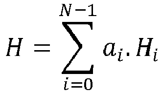
où N représente la quantité de capteurs à effet Hall dont les mesures sont considérées, Hi représente la mesure effectuée par le capteur à effet Hall représenté par l'index i et ai représente un coefficient prédéfini de pondération de chaque mesure. Chaque coefficient de pondération ai peut être défini de manière expérimentale, notamment en fonction de l'agencement géométrique relatif des capteurs à effet Hall 110, 111, 112, 113.In a
where N represents the amount of Hall effect sensors whose measurements are considered, H i represents the measurement made by the Hall effect sensor represented by the index i and a i represents a predefined weighting coefficient of each measurement. Each weighting coefficient a i can be defined so experimental, in particular according to the relative geometrical arrangement of the
Dans une étape 303, l'équipement de surveillance 130 compare la valeur H de combinaison linéaire déterminée avec un seuil prédéfini Stot. La valeur du seuil Stot peut être prédéfinie en fonction du seuil prédéfini Tsrc et de l'agencement géométrique relatif des capteurs à effet Hall 110, 111, 112, 113.In a
Dans un mode de réalisation particulier, le seuil prédéfini Stot est défini par une moyenne quadratique des seuils prédéfinis Si pondérée par un coefficient L, selon la formule suivante : 
où L est un coefficient égal à ![]()
where L is a coefficient equal to ![]()
Selon un mode de réalisation particulier, chaque coefficient de pondération ai peut être défini selon la formule suivante : 
où K représente un coefficient d'ajustement, par exemple égal à 0,75.According to a particular embodiment, each weighting coefficient a i can be defined according to the following formula:
where K represents an adjustment coefficient, for example equal to 0.75.
Dans une étape 304, l'équipement de surveillance 130 détermine si une présence de source magnétique génératrice de champ magnétique d'intensité supérieure audit seuil prédéfini Tsrc est détectée en fonction de la valeur H de combinaison linéaire desdites mesures obtenues à l'étape 301. La présence d'une telle source magnétique est détectée lorsque la valeur H de combinaison linéaire desdites mesures obtenues à l'étape 301 est supérieure au seuil prédéfini Stot. Si la présence d'une telle source magnétique est détectée, une étape 305 est effectuée ; sinon, il est mis fin à l'algorithme de la
Dans l'étape 305, l'équipement de surveillance 130 génère une alarme représentative d'une détection de présence d'une source magnétique génératrice d'un champ magnétique d'intensité supérieure audit seuil prédéfini Tsrc, c'est-à-dire d'une source magnétique considérée comme pouvant perturber le fonctionnement du dispositif 100. Cette alarme peut être générée grâce à un voyant dédié, ou via un affichage sur un écran de l'équipement de surveillance 130, ou via un message transmis via un réseau de communication auquel l'équipement de surveillance 130 a accès. Plus particulièrement dans le cas d'un compteur électrique intelligent intégrant l'équipement de surveillance 130, l'alarme peut être générée grâce à un message transmis par courants porteurs en ligne via le réseau d'alimentation électrique alimentant l'installation électrique dont la consommation électrique est surveillée par ledit compteur électrique intelligent. Il est ensuite mis fin à l'algorithme de la
L'algorithme de la
La
Dans une étape 401, l'équipement de surveillance 130 obtient des mesures effectuées par les capteurs à effet Hall 110, 111, 112, 113. L'étape 401 est identique à l'étape 301 de l'algorithme de la
Dans une étape 402, l'équipement de surveillance 130 détermine la valeur H de combinaison linéaire des mesures obtenues à l'étape 401. L'étape 402 est identique à l'étape 302 de l'algorithme de la
Dans une étape 403, l'équipement de surveillance 130 compare la valeur H de combinaison linéaire déterminée avec le seuil prédéfini Stot. L'étape 403 est identique à l'étape 303 de l'algorithme de la
Dans une étape 404, l'équipement de surveillance 130 compare, pour chaque capteur à effet Hall identifié par l'index i, la mesure Hi avec le seuil prédéfini Si correspondant.In a
Dans une étape 405, l'équipement de surveillance 130 détermine si une présence de source magnétique génératrice de champ magnétique d'intensité supérieure audit seuil prédéfini Tsrc est détectée par les capteurs à effet Hall 110, 111, 112, 113, que ce soit à titre individuel ou collectif. La présence d'une telle source magnétique est détectée à titre collectif lorsque la valeur H de combinaison linéaire desdites mesures obtenues à l'étape 401 est supérieure au seuil prédéfini Stot. La présence d'une telle source magnétique est détectée à titre individuel par un capteur à effet Hall identifié par l'index i lorsque la mesure Hi obtenue à l'étape 401 est supérieure au seuil prédéfini Si correspondant. Si la présence d'une telle source magnétique est détectée que ce soit à titre individuel ou collectif, une étape 406 est effectuée ; sinon, il est mis fin à l'algorithme de la
Dans l'étape 406, l'équipement de surveillance 130 génère une alarme représentative d'une détection de présence d'une source magnétique génératrice d'un champ magnétique d'intensité supérieure audit seuil prédéfini Tsrc, c'est-à-dire d'une source magnétique considérée comme pouvant perturber le fonctionnement du dispositif 100. Cette alarme peut être générée grâce à un voyant dédié, ou via un affichage sur un écran de l'équipement de surveillance 130, ou via un message transmis via un réseau de communication auquel l'équipement de surveillance 130 a accès. Cette alarme peut distinguer le fait que ladite source magnétique ait été détectée par les capteurs à effet Hall 110, 111, 112, 113 à titre individuel ou à titre collectif. Plus particulièrement dans le cas d'un compteur électrique intelligent intégrant l'équipement de surveillance 130, l'alarme peut être générée grâce à un message transmis par courants porteurs en ligne via le réseau d'alimentation électrique alimentant l'installation électrique dont la consommation électrique est surveillée par ledit compteur électrique intelligent. Il est ensuite mis fin à l'algorithme de la
L'algorithme de la
Ainsi, au vu de tout ce qui précède, la présente invention permet de détecter la présence d'une source magnétique génératrice d'un champ magnétique d'intensité supérieure audit seuil prédéfini Tsrc, alors qu'aucun des capteurs à effet Hall pris indépendamment ne permet de détecter la présence de ladite source magnétique car la mesure effectuée par chaque capteur à effet Hall est inférieure ou égale au seuil prédéfini Si associé audit capteur à effet Hall. La combinaison linéaire des mesures desdits capteurs à effet Hall permet alors de créer un capteur à effet Hall virtuel.Thus, in view of all the above, the present invention makes it possible to detect the presence of a magnetic source generating a magnetic field of intensity greater than said predefined threshold T src , whereas none of the Hall effect sensors taken independently detects the presence of said magnetic source because the measurement made by each Hall effect sensor is less than or equal to the predefined threshold Si associated with said Hall effect sensor. The linear combination of the measurements of said Hall effect sensors then makes it possible to create a virtual Hall effect sensor.
Claims (10)

où i est un index représentatif d'un capteur à effet Hall parmi la pluralité de capteurs à effet Hall, et où L est un coefficient égal à
where i is an index representative of a Hall effect sensor among the plurality of Hall effect sensors, and where L is a coefficient equal to

où Hi représente la mesure effectuée par le capteur à effet Hall représenté par l'index i et ai représente un coefficient prédéfini de pondération de la mesure obtenue du capteur à effet Hall identifié par l'index i, chaque coefficient de pondération ai étant prédéfini selon la formule suivante :

où K est un coefficient d'ajustement.Method according to Claim 4, characterized in that the linear combination value H of said measurements obtained is determined as follows:
where H i represents the measurement made by the Hall effect sensor represented by the index i and a i represents a predetermined coefficient of the measurement weight obtained from Hall effect sensor identified by the index i, each weighting coefficient a i being predefined according to the following formula:
where K is an adjustment coefficient.
Applications Claiming Priority (1)
| Application Number | Priority Date | Filing Date | Title |
|---|---|---|---|
| FR1457151A FR3024239B1 (en) | 2014-07-24 | 2014-07-24 | VIRTUAL HALL EFFECT SENSOR |
Publications (2)
| Publication Number | Publication Date |
|---|---|
| EP2977773A1 true EP2977773A1 (en) | 2016-01-27 |
| EP2977773B1 EP2977773B1 (en) | 2022-03-09 |
Family
ID=51570702
Family Applications (1)
| Application Number | Title | Priority Date | Filing Date |
|---|---|---|---|
| EP15177954.3A Active EP2977773B1 (en) | 2014-07-24 | 2015-07-22 | Virtual hall-effect sensor |
Country Status (3)
| Country | Link |
|---|---|
| EP (1) | EP2977773B1 (en) |
| CN (1) | CN105301528B (en) |
| FR (1) | FR3024239B1 (en) |
Citations (3)
| Publication number | Priority date | Publication date | Assignee | Title |
|---|---|---|---|---|
| US20040021568A1 (en) * | 2002-07-31 | 2004-02-05 | Schlumbergersema Inc. | Magnetic field sensing for tamper identification |
| US20110270553A1 (en) * | 2010-04-30 | 2011-11-03 | Infineon Technologies Ag | Apparatus, Sensor Circuit, and Method for Operating an Apparatus or a Sensor Circuit |
| WO2014106663A1 (en) * | 2013-01-07 | 2014-07-10 | Sagemcom Energy & Telecom Sas | Device and method for remotely reading a meter |
Family Cites Families (3)
| Publication number | Priority date | Publication date | Assignee | Title |
|---|---|---|---|---|
| DE4300529C2 (en) * | 1993-01-12 | 1995-07-13 | Andreas Zierdt | Method and device for determining the spatial arrangement of a direction-sensitive magnetic field sensor |
| US8988072B2 (en) * | 2011-07-21 | 2015-03-24 | Infineon Technologies Ag | Vertical hall sensor with high electrical symmetry |
| CN103245810B (en) * | 2013-05-27 | 2015-09-30 | 沈阳时尚实业有限公司 | A kind of magnetism preventing device of intelligent electric energy meter and anti-magnetism method thereof |
-
2014
- 2014-07-24 FR FR1457151A patent/FR3024239B1/en not_active Expired - Fee Related
-
2015
- 2015-07-22 EP EP15177954.3A patent/EP2977773B1/en active Active
- 2015-07-23 CN CN201510551136.6A patent/CN105301528B/en active Active
Patent Citations (3)
| Publication number | Priority date | Publication date | Assignee | Title |
|---|---|---|---|---|
| US20040021568A1 (en) * | 2002-07-31 | 2004-02-05 | Schlumbergersema Inc. | Magnetic field sensing for tamper identification |
| US20110270553A1 (en) * | 2010-04-30 | 2011-11-03 | Infineon Technologies Ag | Apparatus, Sensor Circuit, and Method for Operating an Apparatus or a Sensor Circuit |
| WO2014106663A1 (en) * | 2013-01-07 | 2014-07-10 | Sagemcom Energy & Telecom Sas | Device and method for remotely reading a meter |
Also Published As
| Publication number | Publication date |
|---|---|
| CN105301528A (en) | 2016-02-03 |
| FR3024239A1 (en) | 2016-01-29 |
| CN105301528B (en) | 2020-12-18 |
| EP2977773B1 (en) | 2022-03-09 |
| FR3024239B1 (en) | 2016-08-19 |
Similar Documents
| Publication | Publication Date | Title |
|---|---|---|
| EP3126783B1 (en) | Device for measuring at least one physical quantity of an electric installation | |
| EP2899821B1 (en) | Control device and electric protection device | |
| EP3220168B1 (en) | Particle sensor in a fluid of a lubrication system | |
| EP2533060B1 (en) | Directional detection of resistive earth fault and medium-voltage conductor breakage | |
| You et al. | Disturbance location determination based on electromechanical wave propagation in FNET/GridEye: a distribution‐level wide‐area measurement system | |
| FR2987680A1 (en) | METHOD FOR MEASURING CURRENT IN AN ELECTRICITY NETWORK | |
| EP3428666B1 (en) | Electrical switching device and associated method for detecting wear | |
| US10135200B2 (en) | Embedded platform in electrical cables | |
| FR3012253A1 (en) | ELECTRIC CABLE SECTION DETECTING CIRCUIT BREAKER AND METHOD FOR CONTROLLING SUCH CIRCUIT BREAKER | |
| FR2964772A1 (en) | DEVICE FOR PROTECTING AN ELECTRONIC PRINTED CIRCUIT. | |
| EP2977773B1 (en) | Virtual hall-effect sensor | |
| FR2994275A1 (en) | SYSTEM FOR DETECTING AN IMPEDANCE VARIATION OF A NEUTRAL CONDUCTOR, TRANSFORMATION STATION COMPRISING SUCH A SYSTEM AND METHOD FOR DETECTING AN IMPEDANCE VARIATION OF A NEUTRAL CONDUCTOR WITH SUCH A SYSTEM | |
| EP3051298B1 (en) | Current sensor and electrical network comprising such a current sensor | |
| JP6005449B2 (en) | Gas meter cutoff judgment device | |
| FR3029294B1 (en) | METHOD FOR DETECTING AN INCOHERENCE BETWEEN A CONTROLLED STATE AND A REAL STATE OF A CUTTING MEMBER | |
| EP2963755B1 (en) | System for monitoring a capacitor bank and electrical installation comprising such a system | |
| JP2021083293A (en) | Abnormality detection system, distribution board system, abnormality detection method and program | |
| EP2985612B1 (en) | Method for detecting fraud in an electric meter | |
| FR3070790A1 (en) | ELECTRICAL SWITCHING DEVICE AND ASSOCIATED CONFIGURATION AND DIAGNOSTIC METHODS | |
| EP2674724B1 (en) | Detector with astable output | |
| WO2023135377A1 (en) | Movable or fixed electric fence sensor and electric fence assembly incorporating such a sensor | |
| EP4080185A1 (en) | Method and device for detecting pressure anomalies in a fluid line | |
| EP3182287A1 (en) | A method and a system for monitoring the reliability of at least one piece of electronic equipment installed in an aircraft | |
| EP3320353B1 (en) | Device intended for operating in a hostile environment | |
| EP3009850B1 (en) | Measuring equipment comprising means for detecting magnetic fraud |
Legal Events
| Date | Code | Title | Description |
|---|---|---|---|
| PUAI | Public reference made under article 153(3) epc to a published international application that has entered the european phase |
Free format text: ORIGINAL CODE: 0009012 |
|
| AK | Designated contracting states |
Kind code of ref document: A1 Designated state(s): AL AT BE BG CH CY CZ DE DK EE ES FI FR GB GR HR HU IE IS IT LI LT LU LV MC MK MT NL NO PL PT RO RS SE SI SK SM TR |
|
| AX | Request for extension of the european patent |
Extension state: BA ME |
|
| STAA | Information on the status of an ep patent application or granted ep patent |
Free format text: STATUS: REQUEST FOR EXAMINATION WAS MADE |
|
| 17P | Request for examination filed |
Effective date: 20160708 |
|
| RBV | Designated contracting states (corrected) |
Designated state(s): AL AT BE BG CH CY CZ DE DK EE ES FI FR GB GR HR HU IE IS IT LI LT LU LV MC MK MT NL NO PL PT RO RS SE SI SK SM TR |
|
| GRAP | Despatch of communication of intention to grant a patent |
Free format text: ORIGINAL CODE: EPIDOSNIGR1 |
|
| STAA | Information on the status of an ep patent application or granted ep patent |
Free format text: STATUS: GRANT OF PATENT IS INTENDED |
|
| INTG | Intention to grant announced |
Effective date: 20210416 |
|
| GRAJ | Information related to disapproval of communication of intention to grant by the applicant or resumption of examination proceedings by the epo deleted |
Free format text: ORIGINAL CODE: EPIDOSDIGR1 |
|
| STAA | Information on the status of an ep patent application or granted ep patent |
Free format text: STATUS: REQUEST FOR EXAMINATION WAS MADE |
|
| INTC | Intention to grant announced (deleted) | ||
| GRAP | Despatch of communication of intention to grant a patent |
Free format text: ORIGINAL CODE: EPIDOSNIGR1 |
|
| STAA | Information on the status of an ep patent application or granted ep patent |
Free format text: STATUS: GRANT OF PATENT IS INTENDED |
|
| INTG | Intention to grant announced |
Effective date: 20210928 |
|
| GRAS | Grant fee paid |
Free format text: ORIGINAL CODE: EPIDOSNIGR3 |
|
| GRAA | (expected) grant |
Free format text: ORIGINAL CODE: 0009210 |
|
| STAA | Information on the status of an ep patent application or granted ep patent |
Free format text: STATUS: THE PATENT HAS BEEN GRANTED |
|
| AK | Designated contracting states |
Kind code of ref document: B1 Designated state(s): AL AT BE BG CH CY CZ DE DK EE ES FI FR GB GR HR HU IE IS IT LI LT LU LV MC MK MT NL NO PL PT RO RS SE SI SK SM TR |
|
| REG | Reference to a national code |
Ref country code: GB Ref legal event code: FG4D Free format text: NOT ENGLISH |
|
| REG | Reference to a national code |
Ref country code: CH Ref legal event code: EP Ref country code: AT Ref legal event code: REF Ref document number: 1474604 Country of ref document: AT Kind code of ref document: T Effective date: 20220315 |
|
| REG | Reference to a national code |
Ref country code: DE Ref legal event code: R096 Ref document number: 602015077366 Country of ref document: DE |
|
| REG | Reference to a national code |
Ref country code: IE Ref legal event code: FG4D Free format text: LANGUAGE OF EP DOCUMENT: FRENCH |
|
| REG | Reference to a national code |
Ref country code: LT Ref legal event code: MG9D |
|
| REG | Reference to a national code |
Ref country code: NL Ref legal event code: MP Effective date: 20220309 |
|
| PG25 | Lapsed in a contracting state [announced via postgrant information from national office to epo] |
Ref country code: SE Free format text: LAPSE BECAUSE OF FAILURE TO SUBMIT A TRANSLATION OF THE DESCRIPTION OR TO PAY THE FEE WITHIN THE PRESCRIBED TIME-LIMIT Effective date: 20220309 Ref country code: RS Free format text: LAPSE BECAUSE OF FAILURE TO SUBMIT A TRANSLATION OF THE DESCRIPTION OR TO PAY THE FEE WITHIN THE PRESCRIBED TIME-LIMIT Effective date: 20220309 Ref country code: NO Free format text: LAPSE BECAUSE OF FAILURE TO SUBMIT A TRANSLATION OF THE DESCRIPTION OR TO PAY THE FEE WITHIN THE PRESCRIBED TIME-LIMIT Effective date: 20220609 Ref country code: LT Free format text: LAPSE BECAUSE OF FAILURE TO SUBMIT A TRANSLATION OF THE DESCRIPTION OR TO PAY THE FEE WITHIN THE PRESCRIBED TIME-LIMIT Effective date: 20220309 Ref country code: HR Free format text: LAPSE BECAUSE OF FAILURE TO SUBMIT A TRANSLATION OF THE DESCRIPTION OR TO PAY THE FEE WITHIN THE PRESCRIBED TIME-LIMIT Effective date: 20220309 Ref country code: BG Free format text: LAPSE BECAUSE OF FAILURE TO SUBMIT A TRANSLATION OF THE DESCRIPTION OR TO PAY THE FEE WITHIN THE PRESCRIBED TIME-LIMIT Effective date: 20220609 |
|
| REG | Reference to a national code |
Ref country code: AT Ref legal event code: MK05 Ref document number: 1474604 Country of ref document: AT Kind code of ref document: T Effective date: 20220309 |
|
| PG25 | Lapsed in a contracting state [announced via postgrant information from national office to epo] |
Ref country code: LV Free format text: LAPSE BECAUSE OF FAILURE TO SUBMIT A TRANSLATION OF THE DESCRIPTION OR TO PAY THE FEE WITHIN THE PRESCRIBED TIME-LIMIT Effective date: 20220309 Ref country code: GR Free format text: LAPSE BECAUSE OF FAILURE TO SUBMIT A TRANSLATION OF THE DESCRIPTION OR TO PAY THE FEE WITHIN THE PRESCRIBED TIME-LIMIT Effective date: 20220610 Ref country code: FI Free format text: LAPSE BECAUSE OF FAILURE TO SUBMIT A TRANSLATION OF THE DESCRIPTION OR TO PAY THE FEE WITHIN THE PRESCRIBED TIME-LIMIT Effective date: 20220309 |
|
| PG25 | Lapsed in a contracting state [announced via postgrant information from national office to epo] |
Ref country code: NL Free format text: LAPSE BECAUSE OF FAILURE TO SUBMIT A TRANSLATION OF THE DESCRIPTION OR TO PAY THE FEE WITHIN THE PRESCRIBED TIME-LIMIT Effective date: 20220309 |
|
| PG25 | Lapsed in a contracting state [announced via postgrant information from national office to epo] |
Ref country code: SM Free format text: LAPSE BECAUSE OF FAILURE TO SUBMIT A TRANSLATION OF THE DESCRIPTION OR TO PAY THE FEE WITHIN THE PRESCRIBED TIME-LIMIT Effective date: 20220309 Ref country code: SK Free format text: LAPSE BECAUSE OF FAILURE TO SUBMIT A TRANSLATION OF THE DESCRIPTION OR TO PAY THE FEE WITHIN THE PRESCRIBED TIME-LIMIT Effective date: 20220309 Ref country code: RO Free format text: LAPSE BECAUSE OF FAILURE TO SUBMIT A TRANSLATION OF THE DESCRIPTION OR TO PAY THE FEE WITHIN THE PRESCRIBED TIME-LIMIT Effective date: 20220309 Ref country code: PT Free format text: LAPSE BECAUSE OF FAILURE TO SUBMIT A TRANSLATION OF THE DESCRIPTION OR TO PAY THE FEE WITHIN THE PRESCRIBED TIME-LIMIT Effective date: 20220711 Ref country code: ES Free format text: LAPSE BECAUSE OF FAILURE TO SUBMIT A TRANSLATION OF THE DESCRIPTION OR TO PAY THE FEE WITHIN THE PRESCRIBED TIME-LIMIT Effective date: 20220309 Ref country code: EE Free format text: LAPSE BECAUSE OF FAILURE TO SUBMIT A TRANSLATION OF THE DESCRIPTION OR TO PAY THE FEE WITHIN THE PRESCRIBED TIME-LIMIT Effective date: 20220309 Ref country code: CZ Free format text: LAPSE BECAUSE OF FAILURE TO SUBMIT A TRANSLATION OF THE DESCRIPTION OR TO PAY THE FEE WITHIN THE PRESCRIBED TIME-LIMIT Effective date: 20220309 Ref country code: AT Free format text: LAPSE BECAUSE OF FAILURE TO SUBMIT A TRANSLATION OF THE DESCRIPTION OR TO PAY THE FEE WITHIN THE PRESCRIBED TIME-LIMIT Effective date: 20220309 |
|
| PG25 | Lapsed in a contracting state [announced via postgrant information from national office to epo] |
Ref country code: PL Free format text: LAPSE BECAUSE OF FAILURE TO SUBMIT A TRANSLATION OF THE DESCRIPTION OR TO PAY THE FEE WITHIN THE PRESCRIBED TIME-LIMIT Effective date: 20220309 Ref country code: IS Free format text: LAPSE BECAUSE OF FAILURE TO SUBMIT A TRANSLATION OF THE DESCRIPTION OR TO PAY THE FEE WITHIN THE PRESCRIBED TIME-LIMIT Effective date: 20220709 Ref country code: AL Free format text: LAPSE BECAUSE OF FAILURE TO SUBMIT A TRANSLATION OF THE DESCRIPTION OR TO PAY THE FEE WITHIN THE PRESCRIBED TIME-LIMIT Effective date: 20220309 |
|
| REG | Reference to a national code |
Ref country code: DE Ref legal event code: R097 Ref document number: 602015077366 Country of ref document: DE |
|
| PLBE | No opposition filed within time limit |
Free format text: ORIGINAL CODE: 0009261 |
|
| STAA | Information on the status of an ep patent application or granted ep patent |
Free format text: STATUS: NO OPPOSITION FILED WITHIN TIME LIMIT |
|
| PG25 | Lapsed in a contracting state [announced via postgrant information from national office to epo] |
Ref country code: DK Free format text: LAPSE BECAUSE OF FAILURE TO SUBMIT A TRANSLATION OF THE DESCRIPTION OR TO PAY THE FEE WITHIN THE PRESCRIBED TIME-LIMIT Effective date: 20220309 |
|
| 26N | No opposition filed |
Effective date: 20221212 |
|
| PG25 | Lapsed in a contracting state [announced via postgrant information from national office to epo] |
Ref country code: SI Free format text: LAPSE BECAUSE OF FAILURE TO SUBMIT A TRANSLATION OF THE DESCRIPTION OR TO PAY THE FEE WITHIN THE PRESCRIBED TIME-LIMIT Effective date: 20220309 Ref country code: MC Free format text: LAPSE BECAUSE OF FAILURE TO SUBMIT A TRANSLATION OF THE DESCRIPTION OR TO PAY THE FEE WITHIN THE PRESCRIBED TIME-LIMIT Effective date: 20220309 |
|
| REG | Reference to a national code |
Ref country code: CH Ref legal event code: PL |
|
| REG | Reference to a national code |
Ref country code: BE Ref legal event code: MM Effective date: 20220731 |
|
| PG25 | Lapsed in a contracting state [announced via postgrant information from national office to epo] |
Ref country code: LU Free format text: LAPSE BECAUSE OF NON-PAYMENT OF DUE FEES Effective date: 20220722 Ref country code: LI Free format text: LAPSE BECAUSE OF NON-PAYMENT OF DUE FEES Effective date: 20220731 Ref country code: CH Free format text: LAPSE BECAUSE OF NON-PAYMENT OF DUE FEES Effective date: 20220731 |
|
| PG25 | Lapsed in a contracting state [announced via postgrant information from national office to epo] |
Ref country code: BE Free format text: LAPSE BECAUSE OF NON-PAYMENT OF DUE FEES Effective date: 20220731 |
|
| PG25 | Lapsed in a contracting state [announced via postgrant information from national office to epo] |
Ref country code: IT Free format text: LAPSE BECAUSE OF FAILURE TO SUBMIT A TRANSLATION OF THE DESCRIPTION OR TO PAY THE FEE WITHIN THE PRESCRIBED TIME-LIMIT Effective date: 20220309 Ref country code: IE Free format text: LAPSE BECAUSE OF NON-PAYMENT OF DUE FEES Effective date: 20220722 |
|
| PGFP | Annual fee paid to national office [announced via postgrant information from national office to epo] |
Ref country code: FR Payment date: 20230621 Year of fee payment: 9 |
|
| PGFP | Annual fee paid to national office [announced via postgrant information from national office to epo] |
Ref country code: GB Payment date: 20230620 Year of fee payment: 9 |
|
| PGFP | Annual fee paid to national office [announced via postgrant information from national office to epo] |
Ref country code: DE Payment date: 20230620 Year of fee payment: 9 |
|
| PG25 | Lapsed in a contracting state [announced via postgrant information from national office to epo] |
Ref country code: HU Free format text: LAPSE BECAUSE OF FAILURE TO SUBMIT A TRANSLATION OF THE DESCRIPTION OR TO PAY THE FEE WITHIN THE PRESCRIBED TIME-LIMIT; INVALID AB INITIO Effective date: 20150722 |