US20120249278A1 - System and method for operating a tap changer - Google Patents
System and method for operating a tap changer Download PDFInfo
- Publication number
- US20120249278A1 US20120249278A1 US13/077,504 US201113077504A US2012249278A1 US 20120249278 A1 US20120249278 A1 US 20120249278A1 US 201113077504 A US201113077504 A US 201113077504A US 2012249278 A1 US2012249278 A1 US 2012249278A1
- Authority
- US
- United States
- Prior art keywords
- tap
- voltage
- time period
- average
- voltage profile
- Prior art date
- Legal status (The legal status is an assumption and is not a legal conclusion. Google has not performed a legal analysis and makes no representation as to the accuracy of the status listed.)
- Granted
Links
- 238000000034 method Methods 0.000 title claims abstract description 33
- 238000004422 calculation algorithm Methods 0.000 claims description 11
- 230000009467 reduction Effects 0.000 claims description 6
- 238000004804 winding Methods 0.000 description 15
- 230000005540 biological transmission Effects 0.000 description 10
- 230000005611 electricity Effects 0.000 description 7
- 238000007726 management method Methods 0.000 description 3
- 238000013459 approach Methods 0.000 description 2
- 239000003990 capacitor Substances 0.000 description 2
- 230000008859 change Effects 0.000 description 2
- 230000003247 decreasing effect Effects 0.000 description 2
- 238000010586 diagram Methods 0.000 description 2
- 238000012423 maintenance Methods 0.000 description 2
- 238000012986 modification Methods 0.000 description 2
- 230000004048 modification Effects 0.000 description 2
- 238000012544 monitoring process Methods 0.000 description 2
- 208000032369 Primary transmission Diseases 0.000 description 1
- 208000032370 Secondary transmission Diseases 0.000 description 1
- 238000013528 artificial neural network Methods 0.000 description 1
- 238000004364 calculation method Methods 0.000 description 1
- 238000004590 computer program Methods 0.000 description 1
- 238000013277 forecasting method Methods 0.000 description 1
- 238000005457 optimization Methods 0.000 description 1
- 238000010248 power generation Methods 0.000 description 1
- 230000008569 process Effects 0.000 description 1
- 230000001105 regulatory effect Effects 0.000 description 1
- 230000004044 response Effects 0.000 description 1
- 238000012546 transfer Methods 0.000 description 1
Images


Classifications
-
- H—ELECTRICITY
- H02—GENERATION; CONVERSION OR DISTRIBUTION OF ELECTRIC POWER
- H02J—CIRCUIT ARRANGEMENTS OR SYSTEMS FOR SUPPLYING OR DISTRIBUTING ELECTRIC POWER; SYSTEMS FOR STORING ELECTRIC ENERGY
- H02J3/00—Circuit arrangements for ac mains or ac distribution networks
- H02J3/12—Circuit arrangements for ac mains or ac distribution networks for adjusting voltage in ac networks by changing a characteristic of the network load
- H02J3/16—Circuit arrangements for ac mains or ac distribution networks for adjusting voltage in ac networks by changing a characteristic of the network load by adjustment of reactive power
-
- G—PHYSICS
- G05—CONTROLLING; REGULATING
- G05F—SYSTEMS FOR REGULATING ELECTRIC OR MAGNETIC VARIABLES
- G05F1/00—Automatic systems in which deviations of an electric quantity from one or more predetermined values are detected at the output of the system and fed back to a device within the system to restore the detected quantity to its predetermined value or values, i.e. retroactive systems
- G05F1/10—Regulating voltage or current
- G05F1/12—Regulating voltage or current wherein the variable actually regulated by the final control device is ac
- G05F1/14—Regulating voltage or current wherein the variable actually regulated by the final control device is ac using tap transformers or tap changing inductors as final control devices
-
- H—ELECTRICITY
- H02—GENERATION; CONVERSION OR DISTRIBUTION OF ELECTRIC POWER
- H02J—CIRCUIT ARRANGEMENTS OR SYSTEMS FOR SUPPLYING OR DISTRIBUTING ELECTRIC POWER; SYSTEMS FOR STORING ELECTRIC ENERGY
- H02J3/00—Circuit arrangements for ac mains or ac distribution networks
-
- H—ELECTRICITY
- H02—GENERATION; CONVERSION OR DISTRIBUTION OF ELECTRIC POWER
- H02J—CIRCUIT ARRANGEMENTS OR SYSTEMS FOR SUPPLYING OR DISTRIBUTING ELECTRIC POWER; SYSTEMS FOR STORING ELECTRIC ENERGY
- H02J3/00—Circuit arrangements for ac mains or ac distribution networks
- H02J3/003—Load forecast, e.g. methods or systems for forecasting future load demand
-
- H—ELECTRICITY
- H02—GENERATION; CONVERSION OR DISTRIBUTION OF ELECTRIC POWER
- H02J—CIRCUIT ARRANGEMENTS OR SYSTEMS FOR SUPPLYING OR DISTRIBUTING ELECTRIC POWER; SYSTEMS FOR STORING ELECTRIC ENERGY
- H02J3/00—Circuit arrangements for ac mains or ac distribution networks
- H02J3/18—Arrangements for adjusting, eliminating or compensating reactive power in networks
- H02J3/1878—Arrangements for adjusting, eliminating or compensating reactive power in networks using tap changing or phase shifting transformers
-
- H—ELECTRICITY
- H02—GENERATION; CONVERSION OR DISTRIBUTION OF ELECTRIC POWER
- H02P—CONTROL OR REGULATION OF ELECTRIC MOTORS, ELECTRIC GENERATORS OR DYNAMO-ELECTRIC CONVERTERS; CONTROLLING TRANSFORMERS, REACTORS OR CHOKE COILS
- H02P13/00—Arrangements for controlling transformers, reactors or choke coils, for the purpose of obtaining a desired output
- H02P13/06—Arrangements for controlling transformers, reactors or choke coils, for the purpose of obtaining a desired output by tap-changing; by rearranging interconnections of windings
-
- Y—GENERAL TAGGING OF NEW TECHNOLOGICAL DEVELOPMENTS; GENERAL TAGGING OF CROSS-SECTIONAL TECHNOLOGIES SPANNING OVER SEVERAL SECTIONS OF THE IPC; TECHNICAL SUBJECTS COVERED BY FORMER USPC CROSS-REFERENCE ART COLLECTIONS [XRACs] AND DIGESTS
- Y02—TECHNOLOGIES OR APPLICATIONS FOR MITIGATION OR ADAPTATION AGAINST CLIMATE CHANGE
- Y02E—REDUCTION OF GREENHOUSE GAS [GHG] EMISSIONS, RELATED TO ENERGY GENERATION, TRANSMISSION OR DISTRIBUTION
- Y02E40/00—Technologies for an efficient electrical power generation, transmission or distribution
- Y02E40/30—Reactive power compensation
-
- Y—GENERAL TAGGING OF NEW TECHNOLOGICAL DEVELOPMENTS; GENERAL TAGGING OF CROSS-SECTIONAL TECHNOLOGIES SPANNING OVER SEVERAL SECTIONS OF THE IPC; TECHNICAL SUBJECTS COVERED BY FORMER USPC CROSS-REFERENCE ART COLLECTIONS [XRACs] AND DIGESTS
- Y04—INFORMATION OR COMMUNICATION TECHNOLOGIES HAVING AN IMPACT ON OTHER TECHNOLOGY AREAS
- Y04S—SYSTEMS INTEGRATING TECHNOLOGIES RELATED TO POWER NETWORK OPERATION, COMMUNICATION OR INFORMATION TECHNOLOGIES FOR IMPROVING THE ELECTRICAL POWER GENERATION, TRANSMISSION, DISTRIBUTION, MANAGEMENT OR USAGE, i.e. SMART GRIDS
- Y04S10/00—Systems supporting electrical power generation, transmission or distribution
- Y04S10/50—Systems or methods supporting the power network operation or management, involving a certain degree of interaction with the load-side end user applications
Definitions
- Embodiments of the invention relates generally to an electric power grid and more specifically to control of tap changers for voltage regulators or transformers.
- the basic structure of an electric power system comprises various hardware elements such as generators, transformers, and real-time monitoring equipment, and software such as power flow analysis software, fault detection software, and restoration software for generation, transmission, and distribution of electricity.
- a method for operating a tap changer of a transformer or a voltage regulator includes obtaining a load forecast for a time period and determining an average voltage profile for the time period based on the load forecast. The method also includes estimating tap positions of the tap changer for leveling the average voltage profile during the time period and providing switching signal commands to the tap changer based on the estimated tap positions.
- a tap changer control system including a load forecasting module, a load flow module, a tap position identification module and a switching circuitry.
- the load forecasting module determines a load forecast for a time period and the load flow module determines an average voltage profile for the time period of interest.
- the tap position identification module estimates tap positions for a tap changer of a transformer or a voltage regulator for leveling the average voltage profile and the switching circuitry adjusts taps of the tap changer based on the estimated tap positions.
- computer-readable medium comprising non-transitory computer-readable instructions that, when executed by a processor, cause the processor to perform a method of operating a tap changer of a transformer or a voltage regulator in a power grid.
- the method includes obtaining a load forecast for a time period and determining an average voltage profile for the time period based on the load forecast.
- the method also includes estimating tap positions of the tap changer for leveling the average voltage profile during the time period and providing switching signal commands to the tap changer based on the estimated tap positions.
- FIG. 1 is a diagrammatical representation of an overall electric system
- FIG. 2 is a schematic representation of a conventional tap changer
- FIG. 3 is a flow chart representing a method of operating tap changers in accordance with an embodiment of the present invention
- FIG. 4 is a graphical representation of forecasted and resulting average voltage profiles.
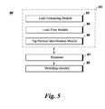
- FIG. 5 is a diagrammatical representation of a tap changer control system in accordance with an embodiment of the present invention.
- FIG. 1 illustrates a single line diagram of an overall electric system 10 from generation to utilization.
- the electric system 10 includes a generating station 12 , a transmission substation 14 , local substations or distribution substations 16 and loads 18 .
- Generating station 12 may comprise a hydropower generating station, a thermal power generating station, a wind power generating station, or a solar power generating station, for example.
- Generating station 12 generates electricity at a generating station voltage which is typically in the range of 4 kV to 13 kV.
- the generating station voltage is stepped up to a higher transmission level voltage such as 110 kV and above by a generating station transformer (not shown) for more efficient transfer of the electricity.
- the electricity at the transmission level voltage is transmitted to transmission substation 14 by primary transmission lines 20 that are configured to carry electricity long distances.
- a reduction in voltage occurs for distribution to other points in the system through secondary transmission lines 22 .
- Further voltage reductions for commercial and industrial or residential loads 18 may occur at distribution substation 16 .
- the distribution substation 16 may supply electricity at voltages in the range of 4 kV to 34.5 kV, for example.
- the voltages may further be reduced by one or two more levels at distribution substation 16 or other local substations (not shown) receiving power from distribution substation 16 to supply the electricity to residential loads at lower voltages such as 120 V or 240 V.
- fixed step down transformers may be used for stepping down the voltage at transmission substation 14 or distribution substation 16 .
- voltage regulators may be placed within the distribution system or at the distribution substation 16 , for regulating voltage and reactive power further down the network from the voltage regulator.
- OLTCs On-Load Tap Changers
- tap changer is used to describe both voltage regulators as well as OLTCs.
- the voltage regulators and OLTCs may be used interchangeably.
- a utility control center 24 is used in the system 10 for operation and maintenance of generating station 12 , transmission substation 14 , and distribution substations 16 .
- Utility control center 24 receives data from these components and also provides control signals to these components.
- Loads 18 may communicate with their respective distribution substations 16 and thus, the utility control center 24 may also receive and transmit information to and from the loads 18 .
- Components of the utility control center 24 include a supervisory control and data acquisition (SCADA) system 26 , an energy management system (EMS) 28 , a demand response management system (DRMS) 30 , and a distribution management system (DMS) 32 .
- SCADA supervisory control and data acquisition
- EMS energy management system
- DRMS demand response management system
- DMS distribution management system
- some of these components may be provided separately in system 10 rather than being integrated in the utility control center 24 .
- all the components may not be necessary and one or more component may be omitted.
- SCADA usually refers to basic control and monitoring of field devices including breakers, switches, capacitors, reclosers, and transformers.
- EMS 28 coordinates and optimizes power generation and transmission
- DMS 32 coordinates power distribution.
- EMS 28 and DMS 32 include applications such as automatic generation control (AGC), load forecasting, OLTC and voltage regulator switching controls, engineering load flow modeling, economic dispatch, energy accounting, interchange transactions, and VAR/voltage control.
- AGC automatic generation control
- load forecasting OLTC and voltage regulator switching controls
- engineering load flow modeling engineering load flow modeling
- economic dispatch energy accounting
- interchange transactions and VAR/voltage control
- VAR/voltage control VAR/voltage control
- FIG. 2 shows a schematic diagram of a conventional voltage regulator 110 .
- Voltage regulator 110 includes a primary winding 42 , a secondary winding 44 , and transformer taps 46 .
- the input and output voltage will be equal.
- the output voltage can be changed. For example, if primary winding 42 has 120 turns and secondary winding 44 has 60 turns then the output to input voltage ratio will be one-half i.e., the output voltage on the secondary winding will be half of the input voltage on the primary winding.
- secondary winding 44 includes voltage taps 46 .
- the output voltage at secondary winding 44 depends on taps between which the load is connected and can vary between 0.9 Vin to 1.1 Vin where Vin is the input voltage on the primary winding 42 .
- a tap changer has 32 taps, out of which 16 are for increasing the voltage (1 to 16 taps) whereas 16 are for decreasing the voltage ( ⁇ 1 to ⁇ 16 taps).
- tap 10 when switched on may yield output voltage of 1.0625 Vin and tap ⁇ 10 will yield output voltage of 0.9375 Vin.
- the actual tap setting and tap will vary depending on the application. For example, for a distribution transformer the output voltage need not go as low as 0.9 Vin but in certain conditions it may be necessary that the output voltage be higher than the input voltage. In another embodiment, the output voltage may need to be lower than 0.9 Vin.
- FIG. 3 shows a method 50 of operating a tap changer in accordance with an embodiment of the present invention.
- the method may be employed by the DMS 32 or EMS 28 ( FIG. 1 ), for example.
- the method includes obtaining a load forecast for a time period or period of interest in step 52 .
- the load forecast may be determined in terms of MVA loading which is indicative of active as well as reactive power for a particular zone.
- the period of interest may be an hour, several hours, a day, or any other suitable time determined by the user or the operator.
- the load forecast is determined for k time steps into the future, where k is again a number determined by the operator.
- Load forecasting is useful in determining how much load each phase can have at any given time of the period of interest. This information may be used for running a load flow on the distribution system to estimate the state in terms of voltages at different points. Load forecasting techniques utilize various factors such as time, weather conditions, customer types, distribution system conditions, and historical load and weather data to provide a load forecast. As will be appreciated by those skilled in the art, load forecasting methods may include similar day approach, various regression models, time series, neural networks, expert systems, fuzzy logic, and statistical learning algorithms.
- a zone refers to an electrical network or a distribution system between two tap changers. For example, if a voltage is stepped down from 69 kV to 34.5 kV through a fixed step down transformer and it is further reduced to 12.47 kV through a second step down transformer at another distribution substation, then the electric system between the 34.5 kV to the second 12.47 kV will be considered as one zone. The voltages then may be determined for each node in the distribution system using the 12.47 kV as a base voltage for each phase of this zone.
- the base voltage value is utilized for normalizing quantities to a common base for calculation purposes.
- Tap changers or voltage regulators may be located at the output of the first step down transformer at the interconnection between the transmission system and the distribution system and at the second 12.47 kV substation to allow further adjustment of distribution voltage in the voltage ratio range of 0.9 to 1.1 per unit (pu).
- a load flow algorithm may be utilized. The load flow algorithm obtains complete voltage angle and magnitude information for each bus or each node on the distribution system for forecasted active and reactive loads. Since determining voltage information based on active and reactive load information is a nonlinear problem, numerical methods are employed to obtain a solution that is within an acceptable tolerance.
- Numerical methods for the load flow algorithm may include William Kersting's backward/forward sweep algorithm, for example.
- the average voltage profile then may be determined by calculating the average of all node voltages in the distribution system for each phase and time period. In one embodiment, the voltage profile is calculated with half of the taps of the tap changer being in the ON position. In other words, if there are 32 taps to the tap changer, each designed to increase the voltage (compared to 0 tap), then the voltage profile is determined with 16 taps of tap the changer being in the ON position. However, in other embodiments, the voltage profile may be determined with different tap positions.
- the tap positions of the tap changer for the period of interest are estimated in step 56 to level the voltage profile.
- leveling the voltage profile means obtaining a constant voltage throughout the period of interest.
- the voltage may not be absolutely constant and may include certain variations but the idea is that the overall voltage profile should not have significant variations.
- a certain amount of voltage called a flat voltage value or desired value may be fixed for the period of interest.
- the flat voltage value may be determined such that the number of tap position changes is minimized.
- the flat voltage value may be an average value of the minimum and maximum voltages of the voltage profile or in yet another embodiment, it could be a median value.
- the difference between the average voltage profile and the flat voltage value may be divided by the voltage per tap. If the flat voltage value is higher compared to the average voltage profile value, then one or more additional taps may be switched on. Otherwise, if the flat voltage value is lower compared to the average voltage profile value, one or more taps may be switched off depending upon the desired primary to secondary voltage ratio. For example, if the flat voltage value desired is 0.98 pu and if the forecasted average voltage at a particular time period is 0.9675 pu then to achieve 0.98 pu, two of the taps may be switched ON assuming 0.00625 pu volts/tap. Similarly, if the voltage is 0.88 pu then 16 taps may be switched ON.
- FIG. 4 shows example plots 70 and 71 of voltage profiles determined in accordance with an embodiment of the present invention.
- Horizontal axis 72 in both plots 70 , 71 represents time in hours whereas vertical axis 74 represents average voltage across all the nodes in a zone in per unit (pu).
- a predicted average voltage profile 76 varies from a minimum value of about two tap settings below the desired flat voltage value (for example, 0.98 pu) to a maximum value of about two tap settings above the desired flat voltage value over the period of 24 hours.
- plot 71 shows the resulting average voltage profile 77 based on the tap changer operation in accordance with an embodiment of the present invention.
- the resulting average voltage profile 77 is calculated with three adjustments in tap settings. The first tap change occurs at time 4 am with a 2 tap setting increase, the second and third tap changes with a 2 tap setting decrease at each adjustment occurs at 8 pm and 10 pm, respectively.
- the voltage may further may be increased or decreased to a defined voltage by a single tap change throughout the period of interest in step 58 .
- the current tap setting is to be reduced by 3 taps (0.00625 pu volts/tap).
- the power flow algorithm with new identified tap settings may be utilized again before obtaining the defined voltage value to verify if any significant changes have occurred to the average voltage profile.
- the defined voltage may be determined by the utility company and is based on a conservation voltage reduction (CVR) factor.
- CVR conservation voltage reduction
- the CVR factor is the percentage reduction in load consumption resulting from a one percent reduction in the voltage. In certain embodiments, CVR factor may range from 0.4 to 1.0.
- FIG. 5 shows a tap changer control system 90 in accordance with an embodiment of the present invention.
- System 90 includes a processor 91 coupled to a memory 93 comprising a load forecasting module 92 for obtaining load forecasts for a time period which may be an hour or 24 hours or any other time as determined by the operator.
- module may refer to or include a computer program or code that provides the described functionality.
- a load flow module 94 runs a power flow on the load forecast data obtained from the load forecasting module 92 and determines an average voltage profile i.e., average voltage across all the nodes for each of the phases in a given zone for the time period.
- the zone may be an electric network between two tap changers.
- a tap position identification module 96 determines a flat voltage value to level the voltage profile and also estimates tap positions throughout the time period to achieve a flat voltage profile. In one embodiment, the module 96 may further identify tap positions for the period of interest to modify the flat voltage profiles to a predetermined voltage value profile wherein the predetermined voltage value may be determined based on the CVR factor.
- Processor 91 processes the data obtained from memory 93 and provides switching signal commands to a switching circuitry 98 .
- switching signal commands may be digital signals with 1 or 0 value. When the switching signal command is 1, it may mean the respective tap should be switched ON. Similarly, when the switching signal command is 0, it may be an indication to switch off the respective tap.
- Switching circuitry 98 When the switching signal command is ON, the respective tap will be switched ON whereas the tap will be switched OFF if the switching signal command is OFF.
- Switching circuitry 98 then provides switching signals to taps of a tap changer based on the modified tap positions determined for the period of interest by the tap position identification module 96 .
Abstract
Description
- Embodiments of the invention relates generally to an electric power grid and more specifically to control of tap changers for voltage regulators or transformers.
- The basic structure of an electric power system comprises various hardware elements such as generators, transformers, and real-time monitoring equipment, and software such as power flow analysis software, fault detection software, and restoration software for generation, transmission, and distribution of electricity.
- In general, power system operators ensure the quality of the power supplied to the customers by maintaining the load bus voltages within their permissible limits. Any changes to the system configuration or in power demands can result in higher or lower voltages in the system. This situation can be improved by reallocating the reactive power generated in the system by adjusting transformer taps, voltage regulator taps, changing generator voltages, and by switching VAR sources such as capacitor banks.
- There are various algorithms available for optimizing operation of tap changer for transformers or voltage regulators. However, most of these algorithms are combined with reactive power control algorithms and thus lead to long convergence times. Further most of these algorithms result in certain transformer taps being switched on and off more times in a day than desired. Frequent switching of transformer taps degrades switching contacts of the transformer taps and increases maintenance requirements.
- Therefore, there is a need for an improved optimization approach to operate tap changers.
- In accordance with an embodiment of the present invention, a method for operating a tap changer of a transformer or a voltage regulator is provided. The method includes obtaining a load forecast for a time period and determining an average voltage profile for the time period based on the load forecast. The method also includes estimating tap positions of the tap changer for leveling the average voltage profile during the time period and providing switching signal commands to the tap changer based on the estimated tap positions.
- In accordance with another embodiment of the present invention, a tap changer control system including a load forecasting module, a load flow module, a tap position identification module and a switching circuitry is provided. The load forecasting module determines a load forecast for a time period and the load flow module determines an average voltage profile for the time period of interest. The tap position identification module estimates tap positions for a tap changer of a transformer or a voltage regulator for leveling the average voltage profile and the switching circuitry adjusts taps of the tap changer based on the estimated tap positions.
- In accordance with yet another embodiment of the present invention, computer-readable medium comprising non-transitory computer-readable instructions that, when executed by a processor, cause the processor to perform a method of operating a tap changer of a transformer or a voltage regulator in a power grid is provided. The method includes obtaining a load forecast for a time period and determining an average voltage profile for the time period based on the load forecast. The method also includes estimating tap positions of the tap changer for leveling the average voltage profile during the time period and providing switching signal commands to the tap changer based on the estimated tap positions.
- These and other features, aspects, and advantages of the present invention will become better understood when the following detailed description is read with reference to the accompanying drawings in which like characters represent like parts throughout the drawings, wherein:
-
FIG. 1 is a diagrammatical representation of an overall electric system; -
FIG. 2 is a schematic representation of a conventional tap changer; -
FIG. 3 is a flow chart representing a method of operating tap changers in accordance with an embodiment of the present invention; -
FIG. 4 is a graphical representation of forecasted and resulting average voltage profiles; and -
FIG. 5 is a diagrammatical representation of a tap changer control system in accordance with an embodiment of the present invention. - When introducing elements of various embodiments of the present invention, the articles “a,” “an,” “the,” and “said” are intended to mean that there are one or more of the elements. The terms “comprising,” “including,” and “having” are intended to be inclusive and mean that there may be additional elements other than the listed elements. Any examples of operating parameters are not exclusive of other parameters of the disclosed embodiments.
-
FIG. 1 illustrates a single line diagram of an overallelectric system 10 from generation to utilization. Theelectric system 10 includes agenerating station 12, atransmission substation 14, local substations ordistribution substations 16 andloads 18. Generatingstation 12 may comprise a hydropower generating station, a thermal power generating station, a wind power generating station, or a solar power generating station, for example. Generatingstation 12 generates electricity at a generating station voltage which is typically in the range of 4 kV to 13 kV. The generating station voltage is stepped up to a higher transmission level voltage such as 110 kV and above by a generating station transformer (not shown) for more efficient transfer of the electricity. - The electricity at the transmission level voltage is transmitted to
transmission substation 14 byprimary transmission lines 20 that are configured to carry electricity long distances. Attransmission substation 14, a reduction in voltage occurs for distribution to other points in the system throughsecondary transmission lines 22. Further voltage reductions for commercial and industrial orresidential loads 18 may occur atdistribution substation 16. Thedistribution substation 16 may supply electricity at voltages in the range of 4 kV to 34.5 kV, for example. The voltages may further be reduced by one or two more levels atdistribution substation 16 or other local substations (not shown) receiving power fromdistribution substation 16 to supply the electricity to residential loads at lower voltages such as 120 V or 240 V. For stepping down the voltage attransmission substation 14 ordistribution substation 16, fixed step down transformers may be used. Typically, the step down transformer is combined with a voltage regulator which can independently modify the output voltage of one or more phases of the transformer over the voltage ratio (=Vout/Vin) range of 0.9 to 1.1. Further voltage regulators (not shown) may be placed within the distribution system or at thedistribution substation 16, for regulating voltage and reactive power further down the network from the voltage regulator. When a voltage regulator is located at the distribution substation, it is call called an On-Load Tap Changers (OLTCs). It should be noted that henceforth the term tap changer is used to describe both voltage regulators as well as OLTCs. Further, the voltage regulators and OLTCs may be used interchangeably. - A
utility control center 24 is used in thesystem 10 for operation and maintenance ofgenerating station 12,transmission substation 14, anddistribution substations 16.Utility control center 24 receives data from these components and also provides control signals to these components.Loads 18 may communicate with theirrespective distribution substations 16 and thus, theutility control center 24 may also receive and transmit information to and from theloads 18. Components of theutility control center 24 include a supervisory control and data acquisition (SCADA)system 26, an energy management system (EMS) 28, a demand response management system (DRMS) 30, and a distribution management system (DMS) 32. In one embodiment, some of these components may be provided separately insystem 10 rather than being integrated in theutility control center 24. In a particular embodiment, all the components may not be necessary and one or more component may be omitted. - As will be appreciated by those skilled in the art, SCADA usually refers to basic control and monitoring of field devices including breakers, switches, capacitors, reclosers, and transformers.
EMS 28 coordinates and optimizes power generation and transmission, whereasDMS 32 coordinates power distribution. EMS 28 andDMS 32 include applications such as automatic generation control (AGC), load forecasting, OLTC and voltage regulator switching controls, engineering load flow modeling, economic dispatch, energy accounting, interchange transactions, and VAR/voltage control. DRMS 30 controls peak demand and produces other economies without major inconvenience to the customer. -
FIG. 2 shows a schematic diagram of a conventional voltage regulator 110. Voltage regulator 110 includes aprimary winding 42, asecondary winding 44, andtransformer taps 46. As will be appreciated by those skilled in the art, when a transformer has an equal number of winding turns on the primary winding and secondary winding, the input and output voltage will be equal. By adding or subtracting the number of turns on the primary winding or secondary winding, the output voltage can be changed. For example, ifprimary winding 42 has 120 turns andsecondary winding 44 has 60 turns then the output to input voltage ratio will be one-half i.e., the output voltage on the secondary winding will be half of the input voltage on the primary winding. Rather than physically changing the number of turns, the turns ratio or voltage ratio can be altered by changing the location of the physical connection to the secondary winding usingtransformer taps 46. InFIG. 2 ,secondary winding 44 includesvoltage taps 46. Thus, in the illustrated embodiment, the output voltage atsecondary winding 44 depends on taps between which the load is connected and can vary between 0.9 Vin to 1.1 Vin where Vin is the input voltage on theprimary winding 42. There may be multiple taps (not shown) in between 0.9 Vin and 1.1 Vin for obtaining voltages in between. Generally a tap changer has 32 taps, out of which 16 are for increasing the voltage (1 to 16 taps) whereas 16 are for decreasing the voltage (−1 to −16 taps). For example, if the output voltage is Vin with no taps employed or switched on, then tap 10 when switched on may yield output voltage of 1.0625 Vin and tap −10 will yield output voltage of 0.9375 Vin. It should be noted that the actual tap setting and tap will vary depending on the application. For example, for a distribution transformer the output voltage need not go as low as 0.9 Vin but in certain conditions it may be necessary that the output voltage be higher than the input voltage. In another embodiment, the output voltage may need to be lower than 0.9 Vin. -
FIG. 3 shows amethod 50 of operating a tap changer in accordance with an embodiment of the present invention. The method may be employed by theDMS 32 or EMS 28 (FIG. 1 ), for example. The method includes obtaining a load forecast for a time period or period of interest instep 52. The load forecast may be determined in terms of MVA loading which is indicative of active as well as reactive power for a particular zone. In one embodiment, the period of interest may be an hour, several hours, a day, or any other suitable time determined by the user or the operator. In another embodiment, the load forecast is determined for k time steps into the future, where k is again a number determined by the operator. - Load forecasting is useful in determining how much load each phase can have at any given time of the period of interest. This information may be used for running a load flow on the distribution system to estimate the state in terms of voltages at different points. Load forecasting techniques utilize various factors such as time, weather conditions, customer types, distribution system conditions, and historical load and weather data to provide a load forecast. As will be appreciated by those skilled in the art, load forecasting methods may include similar day approach, various regression models, time series, neural networks, expert systems, fuzzy logic, and statistical learning algorithms.
- Once the load forecast is obtained for each time step, an average voltage profile may be determined for each zone and phase in
step 54. In one embodiment, a zone refers to an electrical network or a distribution system between two tap changers. For example, if a voltage is stepped down from 69 kV to 34.5 kV through a fixed step down transformer and it is further reduced to 12.47 kV through a second step down transformer at another distribution substation, then the electric system between the 34.5 kV to the second 12.47 kV will be considered as one zone. The voltages then may be determined for each node in the distribution system using the 12.47 kV as a base voltage for each phase of this zone. As will be appreciated by those skilled in the art, the base voltage value is utilized for normalizing quantities to a common base for calculation purposes. Tap changers or voltage regulators may be located at the output of the first step down transformer at the interconnection between the transmission system and the distribution system and at the second 12.47 kV substation to allow further adjustment of distribution voltage in the voltage ratio range of 0.9 to 1.1 per unit (pu). To determine the node voltages, a load flow algorithm may be utilized. The load flow algorithm obtains complete voltage angle and magnitude information for each bus or each node on the distribution system for forecasted active and reactive loads. Since determining voltage information based on active and reactive load information is a nonlinear problem, numerical methods are employed to obtain a solution that is within an acceptable tolerance. Numerical methods for the load flow algorithm may include William Kersting's backward/forward sweep algorithm, for example. The average voltage profile then may be determined by calculating the average of all node voltages in the distribution system for each phase and time period. In one embodiment, the voltage profile is calculated with half of the taps of the tap changer being in the ON position. In other words, if there are 32 taps to the tap changer, each designed to increase the voltage (compared to 0 tap), then the voltage profile is determined with 16 taps of tap the changer being in the ON position. However, in other embodiments, the voltage profile may be determined with different tap positions. - Once the voltage profile is determined in
step 54, the tap positions of the tap changer for the period of interest are estimated instep 56 to level the voltage profile. It should be noted that in one embodiment, leveling the voltage profile means obtaining a constant voltage throughout the period of interest. The voltage may not be absolutely constant and may include certain variations but the idea is that the overall voltage profile should not have significant variations. To level the voltage profile, a certain amount of voltage called a flat voltage value or desired value may be fixed for the period of interest. In one embodiment, the flat voltage value may be determined such that the number of tap position changes is minimized. In another embodiment, the flat voltage value may be an average value of the minimum and maximum voltages of the voltage profile or in yet another embodiment, it could be a median value. For estimating tap positions i.e., to identify approximate number of taps need to be switched ON or OFF, the difference between the average voltage profile and the flat voltage value may be divided by the voltage per tap. If the flat voltage value is higher compared to the average voltage profile value, then one or more additional taps may be switched on. Otherwise, if the flat voltage value is lower compared to the average voltage profile value, one or more taps may be switched off depending upon the desired primary to secondary voltage ratio. For example, if the flat voltage value desired is 0.98 pu and if the forecasted average voltage at a particular time period is 0.9675 pu then to achieve 0.98 pu, two of the taps may be switched ON assuming 0.00625 pu volts/tap. Similarly, if the voltage is 0.88 pu then 16 taps may be switched ON. -
FIG. 4 shows example plots 70 and 71 of voltage profiles determined in accordance with an embodiment of the present invention.Horizontal axis 72 in bothplots vertical axis 74 represents average voltage across all the nodes in a zone in per unit (pu). It can be seen fromplot 70 that a predictedaverage voltage profile 76 varies from a minimum value of about two tap settings below the desired flat voltage value (for example, 0.98 pu) to a maximum value of about two tap settings above the desired flat voltage value over the period of 24 hours. Further,plot 71 shows the resultingaverage voltage profile 77 based on the tap changer operation in accordance with an embodiment of the present invention. The resultingaverage voltage profile 77 is calculated with three adjustments in tap settings. The first tap change occurs attime 4 am with a 2 tap setting increase, the second and third tap changes with a 2 tap setting decrease at each adjustment occurs at 8 pm and 10 pm, respectively. - Referring back to
FIG. 3 , once the flat voltage value is achieved or realized instep 56, the voltage may further may be increased or decreased to a defined voltage by a single tap change throughout the period of interest instep 58. For example, if the flat voltage value is 1.00125 pu and the defined voltage value is 0.98 pu then throughout the period of interest (e.g. 24 hours), the current tap setting is to be reduced by 3 taps (0.00625 pu volts/tap). In one embodiment, the power flow algorithm with new identified tap settings may be utilized again before obtaining the defined voltage value to verify if any significant changes have occurred to the average voltage profile. In another embodiment, the defined voltage may be determined by the utility company and is based on a conservation voltage reduction (CVR) factor. As will be appreciated by those skilled in the art, the CVR factor is the percentage reduction in load consumption resulting from a one percent reduction in the voltage. In certain embodiments, CVR factor may range from 0.4 to 1.0. Once a schedule for switching the taps of tap regulators is determined for the period of interest, the information may be utilized instep 60 for operating the tap changer by providing appropriate switching signal commands to the taps of tap changer byEMS 28 orDMS 32 ofFIG. 1 . -
FIG. 5 shows a tapchanger control system 90 in accordance with an embodiment of the present invention.System 90 includes aprocessor 91 coupled to amemory 93 comprising aload forecasting module 92 for obtaining load forecasts for a time period which may be an hour or 24 hours or any other time as determined by the operator. It should be noted that as used herein, the term module may refer to or include a computer program or code that provides the described functionality. Aload flow module 94 runs a power flow on the load forecast data obtained from theload forecasting module 92 and determines an average voltage profile i.e., average voltage across all the nodes for each of the phases in a given zone for the time period. The zone may be an electric network between two tap changers. A tapposition identification module 96 determines a flat voltage value to level the voltage profile and also estimates tap positions throughout the time period to achieve a flat voltage profile. In one embodiment, themodule 96 may further identify tap positions for the period of interest to modify the flat voltage profiles to a predetermined voltage value profile wherein the predetermined voltage value may be determined based on the CVR factor.Processor 91 processes the data obtained frommemory 93 and provides switching signal commands to a switchingcircuitry 98. In one embodiment, switching signal commands may be digital signals with 1 or 0 value. When the switching signal command is 1, it may mean the respective tap should be switched ON. Similarly, when the switching signal command is 0, it may be an indication to switch off the respective tap. When the switching signal command is ON, the respective tap will be switched ON whereas the tap will be switched OFF if the switching signal command is OFF.Switching circuitry 98 then provides switching signals to taps of a tap changer based on the modified tap positions determined for the period of interest by the tapposition identification module 96. - While only certain features of the invention have been illustrated and described herein, many modifications and changes will occur to those skilled in the art. It is, therefore, to be understood that the appended claims are intended to cover all such modifications and changes as fall within the true spirit of the invention.
Claims (20)
Priority Applications (3)
| Application Number | Priority Date | Filing Date | Title |
|---|---|---|---|
| US13/077,504 US8531173B2 (en) | 2011-03-31 | 2011-03-31 | System and method for operating a tap changer |
| EP12161899.5A EP2506384B1 (en) | 2011-03-31 | 2012-03-28 | System and method for operating a tap changer |
| JP2012075355A JP2012217332A (en) | 2011-03-31 | 2012-03-29 | System and method for operating tap changer |
Applications Claiming Priority (1)
| Application Number | Priority Date | Filing Date | Title |
|---|---|---|---|
| US13/077,504 US8531173B2 (en) | 2011-03-31 | 2011-03-31 | System and method for operating a tap changer |
Publications (2)
| Publication Number | Publication Date |
|---|---|
| US20120249278A1 true US20120249278A1 (en) | 2012-10-04 |
| US8531173B2 US8531173B2 (en) | 2013-09-10 |
Family
ID=46044348
Family Applications (1)
| Application Number | Title | Priority Date | Filing Date |
|---|---|---|---|
| US13/077,504 Active 2031-04-16 US8531173B2 (en) | 2011-03-31 | 2011-03-31 | System and method for operating a tap changer |
Country Status (3)
| Country | Link |
|---|---|
| US (1) | US8531173B2 (en) |
| EP (1) | EP2506384B1 (en) |
| JP (1) | JP2012217332A (en) |
Cited By (19)
| Publication number | Priority date | Publication date | Assignee | Title |
|---|---|---|---|---|
| US20130024033A1 (en) * | 2011-07-20 | 2013-01-24 | General Electric Company | Systems and methods for a power distribution transfer capacity calculator |
| CN103618379A (en) * | 2013-10-22 | 2014-03-05 | 芜湖大学科技园发展有限公司 | Dynamic and extensible grid switch estimation rule engine |
| WO2014152398A1 (en) * | 2013-03-15 | 2014-09-25 | Dominion Resources, Inc. | Electric power system control with measurement of energy demand and energy efficiency using t - distributions |
| US20140303803A1 (en) * | 2011-10-17 | 2014-10-09 | Companhia Hidro Elétrica Do São Francisco - Chesf | Integration system and method for regulating and operating in parallel different high-voltage sources |
| US20140371936A1 (en) * | 2011-11-28 | 2014-12-18 | Expanergy, Llc | System and methods to aggregate instant and forecasted excess renewable energy |
| WO2015078598A1 (en) * | 2013-11-26 | 2015-06-04 | Siemens Aktiengesellschaft | Method for computer-assisted configuration of an electrical power grid |
| WO2015143846A1 (en) * | 2014-03-25 | 2015-10-01 | 国家电网公司 | Online real-time loop closing method based on integration of main network and distribution network |
| US9325174B2 (en) | 2013-03-15 | 2016-04-26 | Dominion Resources, Inc. | Management of energy demand and energy efficiency savings from voltage optimization on electric power systems using AMI-based data analysis |
| US9354641B2 (en) | 2013-03-15 | 2016-05-31 | Dominion Resources, Inc. | Electric power system control with planning of energy demand and energy efficiency using AMI-based data analysis |
| US9367075B1 (en) | 2013-03-15 | 2016-06-14 | Dominion Resources, Inc. | Maximizing of energy delivery system compatibility with voltage optimization using AMI-based data control and analysis |
| WO2017083364A1 (en) * | 2015-11-09 | 2017-05-18 | Abb Schweiz Ag | An ami based volt-var optimization using online model learning |
| US9847639B2 (en) | 2013-03-15 | 2017-12-19 | Dominion Energy, Inc. | Electric power system control with measurement of energy demand and energy efficiency |
| US9909901B2 (en) | 2011-04-22 | 2018-03-06 | Melrok, Llc | Systems and methods to manage and control renewable distributed energy resources |
| US10116135B1 (en) * | 2015-05-08 | 2018-10-30 | Statistics & Control, Inc. | Method and apparatus for voltage control in electric power systems |
| US10732656B2 (en) | 2015-08-24 | 2020-08-04 | Dominion Energy, Inc. | Systems and methods for stabilizer control |
| CN112994040A (en) * | 2021-02-26 | 2021-06-18 | 广东电网有限责任公司韶关供电局 | Transformer voltage adjusting method and transformer |
| US20220107365A1 (en) * | 2020-10-06 | 2022-04-07 | Avo Multi-Amp Corporation D/B/A Megger | Transformer Test System and Method |
| CN114696693A (en) * | 2022-06-01 | 2022-07-01 | 山东东辰节能电力设备有限公司 | Intelligent capacity-regulating transformer |
| US20220246351A1 (en) * | 2020-04-29 | 2022-08-04 | Synergy Inc. | Apparatus and method for improving efficiency of distributed generation facility |
Families Citing this family (12)
| Publication number | Priority date | Publication date | Assignee | Title |
|---|---|---|---|---|
| US9281756B2 (en) * | 2011-11-11 | 2016-03-08 | Varentec, Inc. | Power flow controller with a fractionally rated back-to-back converter |
| CN103257591B (en) * | 2013-03-29 | 2015-11-18 | 国家电网公司 | A kind of tap lifting instruction simulator |
| JP6191229B2 (en) * | 2013-05-15 | 2017-09-06 | 富士電機株式会社 | Tap plan value calculation method, tap command value determination method, control target value calculation method, tap plan value calculation device, tap command value determination device, and tap plan value calculation program |
| US10079915B2 (en) | 2013-10-03 | 2018-09-18 | Duke Energy Corporation | Methods of processing data corresponding to a device that corresponds to a gas, water, or electric grid, and related devices and computer program products |
| JP6448032B2 (en) * | 2015-03-06 | 2019-01-09 | 東京電力ホールディングス株式会社 | DR control system and DR control method |
| JP6752071B2 (en) * | 2016-07-19 | 2020-09-09 | 株式会社日立製作所 | Distribution system system optimization calculation device and system optimization calculation method |
| CN106300396A (en) * | 2016-08-29 | 2017-01-04 | 华北电力大学(保定) | Realize charging electric vehicle switching device and the charging method of three-phrase burden balance |
| US10048709B2 (en) | 2016-09-19 | 2018-08-14 | General Electric Company | System and method for regulation of voltage on an electric power system |
| CN109840646A (en) * | 2017-11-27 | 2019-06-04 | 国网辽宁省电力有限公司经济技术研究院 | Voltage monitoring method based on big data processing |
| AU2019239701B2 (en) * | 2018-03-23 | 2023-06-22 | Electricity North West Property Limited | System for frequency regulation on a power distribution network |
| EP3989382A1 (en) | 2020-10-26 | 2022-04-27 | Siemens Gamesa Renewable Energy Innovation & Technology S.L. | Wind turbine auxiliary power system |
| ES2950896A1 (en) * | 2022-03-10 | 2023-10-16 | Ormazabal Corporate Tech A I E | Method for determining the optimal setpoint and control policy of an automatic voltage regulator for transformers with on-load tap changers (Machine-translation by Google Translate, not legally binding) |
Citations (8)
| Publication number | Priority date | Publication date | Assignee | Title |
|---|---|---|---|---|
| US5541498A (en) * | 1994-12-08 | 1996-07-30 | Beckwith; Robert W. | Distribution circuit var management system using adaptive capacitor controls |
| US6924565B2 (en) * | 2003-08-18 | 2005-08-02 | General Electric Company | Continuous reactive power support for wind turbine generators |
| US20110084672A1 (en) * | 2009-10-13 | 2011-04-14 | Labuschagne Casper A | Systems and methods for synchronized control of electrical power system voltage profiles |
| US20110196546A1 (en) * | 2010-02-09 | 2011-08-11 | Open Access Technology International, Inc. | Systems and methods for demand response and distributed energy resource management |
| US8019697B2 (en) * | 2009-01-14 | 2011-09-13 | Ozog Michael T | Optimization of microgrid energy use and distribution |
| US8195338B2 (en) * | 2008-11-05 | 2012-06-05 | Abb Research Ltd. | Reactive power optimization |
| US20120182157A1 (en) * | 2011-01-14 | 2012-07-19 | Jim Carr | Process, Device and System For Volt/VAR Optimization |
| US8283903B2 (en) * | 2009-02-05 | 2012-10-09 | Abb Research Ltd. | Integrated Voltage and Var optimization process for a distribution system |
Family Cites Families (10)
| Publication number | Priority date | Publication date | Assignee | Title |
|---|---|---|---|---|
| JPS6198126A (en) * | 1984-10-19 | 1986-05-16 | 株式会社東芝 | Voltage controller |
| JPS63299722A (en) * | 1987-05-28 | 1988-12-07 | Hitachi Ltd | Voltage regulation relay |
| JP2734207B2 (en) | 1991-01-17 | 1998-03-30 | 株式会社日立製作所 | System voltage control method and device |
| JP2515076B2 (en) * | 1992-02-28 | 1996-07-10 | 東北電力株式会社 | Method and apparatus for controlling voltage reactive power |
| JPH05328608A (en) | 1992-05-22 | 1993-12-10 | Tohoku Electric Power Co Inc | Equipment for controlling voltage and reactive power |
| JP2002271988A (en) * | 2001-03-07 | 2002-09-20 | Kawamura Electric Inc | Power saving device |
| JP2004173384A (en) | 2002-11-19 | 2004-06-17 | Mitsubishi Electric Corp | Automatic voltage regulator |
| BRPI0601093A (en) | 2006-02-17 | 2007-11-06 | Eduardo Pedrosa Santos | voltage regulating, control, protection and status monitoring system for on-load tap-changers of power transformers, voltage regulators, capacitor banks and the like |
| US7444266B2 (en) | 2006-03-21 | 2008-10-28 | Abb Technology Ltd. | Control system for a transformer or reactor |
| WO2010129691A2 (en) * | 2009-05-07 | 2010-11-11 | Powell Phillip W | Voltage conservation using advanced metering infrastructure and substation centralized voltage control |
-
2011
- 2011-03-31 US US13/077,504 patent/US8531173B2/en active Active
-
2012
- 2012-03-28 EP EP12161899.5A patent/EP2506384B1/en active Active
- 2012-03-29 JP JP2012075355A patent/JP2012217332A/en active Pending
Patent Citations (8)
| Publication number | Priority date | Publication date | Assignee | Title |
|---|---|---|---|---|
| US5541498A (en) * | 1994-12-08 | 1996-07-30 | Beckwith; Robert W. | Distribution circuit var management system using adaptive capacitor controls |
| US6924565B2 (en) * | 2003-08-18 | 2005-08-02 | General Electric Company | Continuous reactive power support for wind turbine generators |
| US8195338B2 (en) * | 2008-11-05 | 2012-06-05 | Abb Research Ltd. | Reactive power optimization |
| US8019697B2 (en) * | 2009-01-14 | 2011-09-13 | Ozog Michael T | Optimization of microgrid energy use and distribution |
| US8283903B2 (en) * | 2009-02-05 | 2012-10-09 | Abb Research Ltd. | Integrated Voltage and Var optimization process for a distribution system |
| US20110084672A1 (en) * | 2009-10-13 | 2011-04-14 | Labuschagne Casper A | Systems and methods for synchronized control of electrical power system voltage profiles |
| US20110196546A1 (en) * | 2010-02-09 | 2011-08-11 | Open Access Technology International, Inc. | Systems and methods for demand response and distributed energy resource management |
| US20120182157A1 (en) * | 2011-01-14 | 2012-07-19 | Jim Carr | Process, Device and System For Volt/VAR Optimization |
Cited By (48)
| Publication number | Priority date | Publication date | Assignee | Title |
|---|---|---|---|---|
| US10768015B2 (en) | 2011-04-22 | 2020-09-08 | Melrok, Llc | Systems and methods to manage and control energy management systems |
| US9909901B2 (en) | 2011-04-22 | 2018-03-06 | Melrok, Llc | Systems and methods to manage and control renewable distributed energy resources |
| US11670959B2 (en) | 2011-04-22 | 2023-06-06 | Melrok, Llc | Systems and methods to manage and control energy management systems |
| US10228265B2 (en) | 2011-04-22 | 2019-03-12 | Melrok, Llc | Systems and methods to manage and control renewable distributed energy resources |
| US20130024033A1 (en) * | 2011-07-20 | 2013-01-24 | General Electric Company | Systems and methods for a power distribution transfer capacity calculator |
| US20140303803A1 (en) * | 2011-10-17 | 2014-10-09 | Companhia Hidro Elétrica Do São Francisco - Chesf | Integration system and method for regulating and operating in parallel different high-voltage sources |
| US9772635B2 (en) * | 2011-10-17 | 2017-09-26 | Companhia Hidro Eléctrica do São Francisco—CHESF | Integration system and method for regulating and operating in parallel different high-voltage sources |
| US11275396B2 (en) | 2011-11-28 | 2022-03-15 | Melrok, Llc | Method and apparatus to assess and control energy efficiency of fan installed in facility of building systems |
| US20140371935A1 (en) * | 2011-11-28 | 2014-12-18 | Expanergy, Llc | System and methods to assess, manage and control distributed renewable energy resources on a grid or microgrid and achieve a 100% renewable energy grid or microgrid from clean, carbon free, and water conserving distributed renewable energy technologies and resources |
| US10545525B2 (en) | 2011-11-28 | 2020-01-28 | Melrok, Llc | Self-driving building energy engine |
| US20140371936A1 (en) * | 2011-11-28 | 2014-12-18 | Expanergy, Llc | System and methods to aggregate instant and forecasted excess renewable energy |
| US9727068B2 (en) | 2011-11-28 | 2017-08-08 | Melrok, Llc | Energy search engine with autonomous control |
| US11860661B2 (en) | 2011-11-28 | 2024-01-02 | Melrok, Llc | Method and apparatus to assess and control energy efficiency of pump installed in facility of building systems |
| US10274985B2 (en) | 2013-03-15 | 2019-04-30 | Dominion Energy, Inc. | Maximizing of energy delivery system compatibility with voltage optimization |
| WO2014152398A1 (en) * | 2013-03-15 | 2014-09-25 | Dominion Resources, Inc. | Electric power system control with measurement of energy demand and energy efficiency using t - distributions |
| US10775815B2 (en) | 2013-03-15 | 2020-09-15 | Dominion Energy, Inc. | Electric power system control with planning of energy demand and energy efficiency using AMI-based data analysis |
| US9678520B2 (en) | 2013-03-15 | 2017-06-13 | Dominion Resources, Inc. | Electric power system control with planning of energy demand and energy efficiency using AMI-based data analysis |
| US9563218B2 (en) | 2013-03-15 | 2017-02-07 | Dominion Resources, Inc. | Electric power system control with measurement of energy demand and energy efficiency using t-distributions |
| US9553453B2 (en) | 2013-03-15 | 2017-01-24 | Dominion Resources, Inc. | Management of energy demand and energy efficiency savings from voltage optimization on electric power systems using AMI-based data analysis |
| US9847639B2 (en) | 2013-03-15 | 2017-12-19 | Dominion Energy, Inc. | Electric power system control with measurement of energy demand and energy efficiency |
| US9887541B2 (en) | 2013-03-15 | 2018-02-06 | Dominion Energy, Inc. | Electric power system control with measurement of energy demand and energy efficiency using T-distributions |
| US9367075B1 (en) | 2013-03-15 | 2016-06-14 | Dominion Resources, Inc. | Maximizing of energy delivery system compatibility with voltage optimization using AMI-based data control and analysis |
| US10768655B2 (en) | 2013-03-15 | 2020-09-08 | Dominion Energy, Inc. | Maximizing of energy delivery system compatibility with voltage optimization |
| US9354641B2 (en) | 2013-03-15 | 2016-05-31 | Dominion Resources, Inc. | Electric power system control with planning of energy demand and energy efficiency using AMI-based data analysis |
| US9325174B2 (en) | 2013-03-15 | 2016-04-26 | Dominion Resources, Inc. | Management of energy demand and energy efficiency savings from voltage optimization on electric power systems using AMI-based data analysis |
| US9582020B2 (en) | 2013-03-15 | 2017-02-28 | Dominion Resources, Inc. | Maximizing of energy delivery system compatibility with voltage optimization using AMI-based data control and analysis |
| US10386872B2 (en) | 2013-03-15 | 2019-08-20 | Dominion Energy, Inc. | Electric power system control with planning of energy demand and energy efficiency using AMI-based data analysis |
| US10476273B2 (en) | 2013-03-15 | 2019-11-12 | Dominion Energy, Inc. | Management of energy demand and energy efficiency savings from voltage optimization on electric power systems using AMI-based data analysis |
| CN105052000A (en) * | 2013-03-15 | 2015-11-11 | 道明尼资源公司 | Electric power system control with measurement of energy demand and energy efficiency using t - distributions |
| US11132012B2 (en) | 2013-03-15 | 2021-09-28 | Dominion Energy, Inc. | Maximizing of energy delivery system compatibility with voltage optimization |
| US10666048B2 (en) | 2013-03-15 | 2020-05-26 | Dominion Energy, Inc. | Electric power system control with measurement of energy demand and energy efficiency using t-distributions |
| US10784688B2 (en) | 2013-03-15 | 2020-09-22 | Dominion Energy, Inc. | Management of energy demand and energy efficiency savings from voltage optimization on electric power systems using AMI-based data analysis |
| CN103618379A (en) * | 2013-10-22 | 2014-03-05 | 芜湖大学科技园发展有限公司 | Dynamic and extensible grid switch estimation rule engine |
| WO2015078598A1 (en) * | 2013-11-26 | 2015-06-04 | Siemens Aktiengesellschaft | Method for computer-assisted configuration of an electrical power grid |
| US10320192B2 (en) | 2013-11-26 | 2019-06-11 | Siemens Aktiengesellschaft | Method for the computer-assisted configuration of an electrical power grid |
| WO2015143846A1 (en) * | 2014-03-25 | 2015-10-01 | 国家电网公司 | Online real-time loop closing method based on integration of main network and distribution network |
| US10116135B1 (en) * | 2015-05-08 | 2018-10-30 | Statistics & Control, Inc. | Method and apparatus for voltage control in electric power systems |
| US11353907B2 (en) | 2015-08-24 | 2022-06-07 | Dominion Energy, Inc. | Systems and methods for stabilizer control |
| US10732656B2 (en) | 2015-08-24 | 2020-08-04 | Dominion Energy, Inc. | Systems and methods for stabilizer control |
| US11755049B2 (en) | 2015-08-24 | 2023-09-12 | Dominion Energy, Inc. | Systems and methods for stabilizer control |
| US10642237B2 (en) | 2015-11-09 | 2020-05-05 | Abb Schweiz Ag | AMI based volt-VAR optimization using online model learning |
| WO2017083364A1 (en) * | 2015-11-09 | 2017-05-18 | Abb Schweiz Ag | An ami based volt-var optimization using online model learning |
| US20220246351A1 (en) * | 2020-04-29 | 2022-08-04 | Synergy Inc. | Apparatus and method for improving efficiency of distributed generation facility |
| US11823833B2 (en) * | 2020-04-29 | 2023-11-21 | Synergy Inc. | Apparatus and method for improving efficiency of distributed generation facility |
| US20220107365A1 (en) * | 2020-10-06 | 2022-04-07 | Avo Multi-Amp Corporation D/B/A Megger | Transformer Test System and Method |
| US11754641B2 (en) * | 2020-10-06 | 2023-09-12 | Avo Multi-Amp Corporation | Transformer test system and method |
| CN112994040A (en) * | 2021-02-26 | 2021-06-18 | 广东电网有限责任公司韶关供电局 | Transformer voltage adjusting method and transformer |
| CN114696693A (en) * | 2022-06-01 | 2022-07-01 | 山东东辰节能电力设备有限公司 | Intelligent capacity-regulating transformer |
Also Published As
| Publication number | Publication date |
|---|---|
| US8531173B2 (en) | 2013-09-10 |
| JP2012217332A (en) | 2012-11-08 |
| EP2506384A1 (en) | 2012-10-03 |
| EP2506384B1 (en) | 2016-08-03 |
Similar Documents
| Publication | Publication Date | Title |
|---|---|---|
| US8531173B2 (en) | System and method for operating a tap changer | |
| US10868425B1 (en) | Method to detect utility disturbance and fault direction | |
| US11157031B2 (en) | Systems and methods for volt/VAR control in electric power management and automation systems | |
| AU2017202088B2 (en) | System and method for load forecasting | |
| KR102101108B1 (en) | Reactive power control methods, devices and systems | |
| Zakariazadeh et al. | A new approach for real time voltage control using demand response in an automated distribution system | |
| US8922175B2 (en) | System and method for operating capacitor banks | |
| Shafiu et al. | Active management and protection of distribution networks with distributed generation | |
| Ishii et al. | Optimal smart functions of large-scale PV inverters in distribution systems | |
| Mirbagheri et al. | Voltage control in active distribution grids: a review and a new set-up procedure for local control laws | |
| CN107846025B (en) | System and method for regulating power system voltage | |
| Švenda et al. | Volt var watt optimization in distribution network with high penetration of renewable energy sources and electric vehicles | |
| Merino et al. | Electra IRP voltage control strategy for enhancing power system stability in future grid architectures | |
| US11146102B2 (en) | Method and control center arrangement for the control of an electrical energy transmission grid, and computer program product | |
| CN117220356B (en) | Multi-time-scale-based annual loss reduction operation optimization method and system for power transmission network | |
| KR102512324B1 (en) | Voltage control device for conservation voltage reduction through voltage optimization control based on load prediction model using renewable energy | |
| Jha et al. | Enhancing Conservation Voltage Reduction using Coordinated Control of Medium and Low Voltage Controllable Devices | |
| Mandal et al. | Coordinated capacitor bank switching using SVC controls | |
| Muthukaruppan | Intelligent and Resilient Management of Smart Distribution System with High Renewable Energy Penetration | |
| JP2023023975A (en) | Voltage control device, voltage control method, and voltage control system | |
| Franz et al. | Analysis of an Advanced Compounding Strategy based on Reactive Power Flow Measurement in the Medium Voltage Network | |
| INPG | NEW APPROACH TO REGULATE LOW VOLTAGE DISTRIBUTION NETWORK |
Legal Events
| Date | Code | Title | Description |
|---|---|---|---|
| AS | Assignment |
Owner name: GENERAL ELECTRIC COMPANY, NEW YORK Free format text: ASSIGNMENT OF ASSIGNORS INTEREST;ASSIGNORS:KROK, MICHAEL JOSEPH;GENC, SAHIKA;REEL/FRAME:026057/0905 Effective date: 20110330 |
|
| FEPP | Fee payment procedure |
Free format text: PAYOR NUMBER ASSIGNED (ORIGINAL EVENT CODE: ASPN); ENTITY STATUS OF PATENT OWNER: LARGE ENTITY |
|
| STCF | Information on status: patent grant |
Free format text: PATENTED CASE |
|
| CC | Certificate of correction | ||
| FPAY | Fee payment |
Year of fee payment: 4 |
|
| MAFP | Maintenance fee payment |
Free format text: PAYMENT OF MAINTENANCE FEE, 8TH YEAR, LARGE ENTITY (ORIGINAL EVENT CODE: M1552); ENTITY STATUS OF PATENT OWNER: LARGE ENTITY Year of fee payment: 8 |
|
| AS | Assignment |
Owner name: GE INFRASTRUCTURE TECHNOLOGY LLC, SOUTH CAROLINA Free format text: ASSIGNMENT OF ASSIGNORS INTEREST;ASSIGNOR:GENERAL ELECTRIC COMPANY;REEL/FRAME:065727/0001 Effective date: 20231110 |