US20120311368A1 - Electronic device and method for detecting power statuses of electronic device - Google Patents
Electronic device and method for detecting power statuses of electronic device Download PDFInfo
- Publication number
- US20120311368A1 US20120311368A1 US13/337,123 US201113337123A US2012311368A1 US 20120311368 A1 US20120311368 A1 US 20120311368A1 US 201113337123 A US201113337123 A US 201113337123A US 2012311368 A1 US2012311368 A1 US 2012311368A1
- Authority
- US
- United States
- Prior art keywords
- power
- status
- bmc
- preset value
- buffer
- Prior art date
- Legal status (The legal status is an assumption and is not a legal conclusion. Google has not performed a legal analysis and makes no representation as to the accuracy of the status listed.)
- Granted
Links
Images


Classifications
-
- G—PHYSICS
- G06—COMPUTING; CALCULATING OR COUNTING
- G06F—ELECTRIC DIGITAL DATA PROCESSING
- G06F1/00—Details not covered by groups G06F3/00 - G06F13/00 and G06F21/00
- G06F1/26—Power supply means, e.g. regulation thereof
- G06F1/28—Supervision thereof, e.g. detecting power-supply failure by out of limits supervision
-
- G—PHYSICS
- G06—COMPUTING; CALCULATING OR COUNTING
- G06F—ELECTRIC DIGITAL DATA PROCESSING
- G06F11/00—Error detection; Error correction; Monitoring
- G06F11/30—Monitoring
- G06F11/3055—Monitoring arrangements for monitoring the status of the computing system or of the computing system component, e.g. monitoring if the computing system is on, off, available, not available
-
- G—PHYSICS
- G06—COMPUTING; CALCULATING OR COUNTING
- G06F—ELECTRIC DIGITAL DATA PROCESSING
- G06F11/00—Error detection; Error correction; Monitoring
- G06F11/30—Monitoring
- G06F11/3058—Monitoring arrangements for monitoring environmental properties or parameters of the computing system or of the computing system component, e.g. monitoring of power, currents, temperature, humidity, position, vibrations
- G06F11/3062—Monitoring arrangements for monitoring environmental properties or parameters of the computing system or of the computing system component, e.g. monitoring of power, currents, temperature, humidity, position, vibrations where the monitored property is the power consumption
-
- G—PHYSICS
- G06—COMPUTING; CALCULATING OR COUNTING
- G06F—ELECTRIC DIGITAL DATA PROCESSING
- G06F11/00—Error detection; Error correction; Monitoring
- G06F11/07—Responding to the occurrence of a fault, e.g. fault tolerance
- G06F11/16—Error detection or correction of the data by redundancy in hardware
- G06F11/20—Error detection or correction of the data by redundancy in hardware using active fault-masking, e.g. by switching out faulty elements or by switching in spare elements
- G06F11/2015—Redundant power supplies
Definitions
- Embodiments of the present disclosure relate to power management technology, and particularly to an electronic device and method for detecting statuses of one or more power supplies in the electronic device.
- One or more power supplies are installed in an electronic device (e.g., a server) to provide reliable power.
- a baseboard management controller (BMC) of the electronic device is used to detect a power status of each power supply through a power management bus. If one of the power supplies is shut down (abnormal status), the BMC records an error message. An administrator may select one of the number of other power supplies to provide power to the electronic device, and remove or shut down a redundant power supply.
- the administrator must set a quantity of the power supplies manually to tell the BMC how many power supplies should be detected. If the administrator doesn't set the quantity of the power supplies which need to be detected, the BMC will output an error message when the redundant power supplies are detected and found to be working abnormally (e.g., removed or shut down). It is an inconvenient and results in mistakes because of human error during the setting operation. Therefore, a more efficient method for detecting the status of all possible parts of the power supplies for an electronic device is desired.
- FIG. 1 is a block diagram of one embodiment of an electronic device including a power status detecting system.
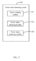
- FIG. 2 is a block diagram of function modules of the power status detecting system included in the electronic device.
- FIG. 3 is a flowchart of one embodiment of a method for detecting power statuses of one or more power supplies in an electronic device.
- FIG. 4 is a detailed flowchart of block S 2 in FIG. 3 .
- FIG. 5 is a detailed flowchart of block S 3 in FIG. 3 .
- non-transitory computer-readable medium may be a hard disk drive, a compact disc, a digital video disc, a tape drive or other suitable storage medium.
- FIG. 1 is a block diagram of one embodiment of an electronic device 2 including a power status detecting system 200 .
- the power status detecting system 200 is stored in a baseboard management controller (BMC) 24 of the electronic device 2 .
- the electronic device 2 further includes a display device 20 , one or more power supplies 21 (only one is shown in FIG. 1 ), an input device 22 , a storage device 23 , and at least one processor 25 .
- the electronic device 2 may be a computer, a server, a tablet device, a mobile phone, or any other computing device.
- FIG. 1 illustrates only one example of the electronic device 2 that may include more or fewer components than as illustrated, or a different configuration of the various components may exist in other embodiments.
- the display device 20 may be a liquid crystal display (LCD) or a cathode ray tube (CRT) display
- the input device 22 may be a mouse, a keyboard, a touch screen, and/or a touchpad used to input computer readable data.
- the power status detecting system 200 is used to detect a power status of each power supply 21 in an electronic device 2 , and record a change in the power status of each power supply 21 in the storage device 23 .
- the power status detecting system 200 may include computerized instructions in the form of one or more programs that are executed by the at least one processor 25 and stored in the storage device 23 (or other memory). A detailed description of the power status detecting system 200 will be given.
- FIG. 2 is a block diagram of function modules of the power status detecting system 200 included in the electronic device 2 .
- the power status detecting system 200 may include one or more modules, for example, a sensor creating module 201 , a power status detecting module 202 , and a power status analyzing module 203 .
- the word “module”, as used herein, refers to logic embodied in hardware or firmware, or to a collection of software instructions, written in a programming language, such as, Java, C, or assembly.
- One or more software instructions in the modules may be embedded in firmware, such as in an EPROM.
- the modules described herein may be implemented as either software and/or hardware modules and may be stored in any type of non-transitory computer-readable medium or other storage device. Some non-limiting examples of non-transitory computer-readable medium include CDs, DVDs, BLU-RAY, flash memory, and hard disk drives.
- FIG. 3 is a flowchart of one embodiment of a method for detecting power statuses of one or more power supplies in an electronic device, such as the electronic device 2 of FIG. 1 .
- additional blocks may be added, others removed, and the ordering of the blocks may be changed.
- the sensor creating module 201 creates a virtual sensor in the BMC 24 .
- the virtual sensor includes a plurality of software modules for detecting power statuses of each power supply 21 at preset intervals.
- the virtual sensor may be stored in a firmware of the BMC 24 .
- the power status detecting module 202 detects a power status of each power supply 21 at a first time cycle “T 1 ” (e.g., one second) when the BMC 24 is started up, and stores one or more detected power statuses into the BMC 24 .
- T 1 a first time cycle
- FIG. 4 A detailed description is given in FIG. 4 .
- the power status of the power supply 21 may include one status defined as normal status and another status defined as abnormal.
- the normal status is a normal working status when the power supply 21 provides power to the electronic device 2
- the abnormal status is any other status, including the power supply 21 being shut down or removed.
- the normal status is recorded as a first preset value
- the abnormal status is recorded as a second preset value.
- the first preset value is represented by a digital “1”
- the second preset value is represented by a digital “0”.
- the power status analyzing module 203 determines any change in the power status of each power supply 21 at a second time cycle (e.g., two seconds) by reference to the virtual sensor, and stores the value, as hereafter established, of the change (change value) in the BMC 24 .
- the change value of the power status of each power supply 21 is determined by analyzing the detected power status of each power supply stored in the BMC 24 .
- the power status analyzing module 203 may determine any change value of the power status of each power supply 21 using a physical sensor. That is to say, in other embodiments, block Si may be removed. A detailed description of block S 3 is given in FIG. 5 .
- the change value of the power status of each power supply 21 is determined as follows. If the power status of one of the power supplies 21 is changed from the first preset value to the second preset value during two sequential first time cycles, the power status analyzing module 203 determines that the power status of the power supply 21 has changed from the normal status to the abnormal status.
- the power status analyzing module 203 determines that the power status of the power supply 21 has changed from the abnormal status to the normal status.
- FIG. 4 is a detailed flowchart of block S 2 in FIG. 3 .
- additional blocks may be added, others removed, and the ordering of the blocks may be changed.
- the power status detecting module 202 allocates a first buffer “buffer 1 ” and a second buffer “buffer 2 ” in a memory of the BMC 24 for each power supply 21 when the BMC 24 is started up.
- the power status detecting module 202 obtains a power status of each power supply 21 at the first time cycle through a power management bus of the BMC 24 .
- the power status detecting module 202 determines if the power status of each power supply 21 is the normal status.
- the power status detecting module 202 controls the power status detecting system 200 to keep a sleep status for the first time cycle “T 1 ,” then the procedure returns to block S 21 .
- FIG. 5 is a detailed flowchart of block S 3 in FIG. 3 .
- additional blocks may be added, others removed, and the ordering of the blocks may be changed.
- the power status analyzing module 203 obtains data stored in the first buffer “buffer 1 ” and the second buffer “buffer 2 ” of each power supply 21 at the second time cycle “T 2 ” using the virtual sensor or the physical sensor.
- the power status analyzing module 203 determines if the data stored in the first buffer and the second buffer of each power supply 21 meet a first condition.
- the power status analyzing module 203 determines that the power status of the power supply 21 has changed from the normal status to the abnormal status, and records an error message in the log file.
- the power status analyzing module 203 does not record an error message concerning the unit or part removed from the power supplies 21 , and the BMC 24 does not output an error messages because the power status of each removed unit or part is not changed.
- the quantity of the power supplies which need to be detected when part or one unit of the power supplies 21 is removed from the electronic device 2 there is no need to preset the quantity of the power supplies which need to be detected when part or one unit of the power supplies 21 is removed from the electronic device 2 .
- the power status analyzing module 203 determines if the data stored in the first buffer and the second buffer of each power supply 21 meet a second condition.
Abstract
Description
- 1. Technical Field
- Embodiments of the present disclosure relate to power management technology, and particularly to an electronic device and method for detecting statuses of one or more power supplies in the electronic device.
- 2. Description of Related Art
- One or more power supplies are installed in an electronic device (e.g., a server) to provide reliable power. A baseboard management controller (BMC) of the electronic device is used to detect a power status of each power supply through a power management bus. If one of the power supplies is shut down (abnormal status), the BMC records an error message. An administrator may select one of the number of other power supplies to provide power to the electronic device, and remove or shut down a redundant power supply.
- In this situation, the administrator must set a quantity of the power supplies manually to tell the BMC how many power supplies should be detected. If the administrator doesn't set the quantity of the power supplies which need to be detected, the BMC will output an error message when the redundant power supplies are detected and found to be working abnormally (e.g., removed or shut down). It is an inconvenient and results in mistakes because of human error during the setting operation. Therefore, a more efficient method for detecting the status of all possible parts of the power supplies for an electronic device is desired.
-
FIG. 1 is a block diagram of one embodiment of an electronic device including a power status detecting system. -
FIG. 2 is a block diagram of function modules of the power status detecting system included in the electronic device. -
FIG. 3 is a flowchart of one embodiment of a method for detecting power statuses of one or more power supplies in an electronic device. -
FIG. 4 is a detailed flowchart of block S2 inFIG. 3 . -
FIG. 5 is a detailed flowchart of block S3 inFIG. 3 . - All of the processes described below may be embodied in, and fully automated via, functional code modules executed by one or more general purpose electronic devices or processors. The code modules may be stored in any type of non-transitory computer-readable medium or other storage device. Some or all of the methods may alternatively be embodied in specialized hardware. Depending on the embodiment, the non-transitory computer-readable medium may be a hard disk drive, a compact disc, a digital video disc, a tape drive or other suitable storage medium.
-
FIG. 1 is a block diagram of one embodiment of anelectronic device 2 including a powerstatus detecting system 200. In the embodiment, the powerstatus detecting system 200 is stored in a baseboard management controller (BMC) 24 of theelectronic device 2. Theelectronic device 2 further includes adisplay device 20, one or more power supplies 21 (only one is shown inFIG. 1 ), aninput device 22, astorage device 23, and at least oneprocessor 25. Theelectronic device 2 may be a computer, a server, a tablet device, a mobile phone, or any other computing device.FIG. 1 illustrates only one example of theelectronic device 2 that may include more or fewer components than as illustrated, or a different configuration of the various components may exist in other embodiments. - The
display device 20 may be a liquid crystal display (LCD) or a cathode ray tube (CRT) display, and theinput device 22 may be a mouse, a keyboard, a touch screen, and/or a touchpad used to input computer readable data. - The power
status detecting system 200 is used to detect a power status of eachpower supply 21 in anelectronic device 2, and record a change in the power status of eachpower supply 21 in thestorage device 23. In one embodiment, the powerstatus detecting system 200 may include computerized instructions in the form of one or more programs that are executed by the at least oneprocessor 25 and stored in the storage device 23 (or other memory). A detailed description of the powerstatus detecting system 200 will be given. -
FIG. 2 is a block diagram of function modules of the powerstatus detecting system 200 included in theelectronic device 2. In one embodiment, the powerstatus detecting system 200 may include one or more modules, for example, asensor creating module 201, a powerstatus detecting module 202, and a powerstatus analyzing module 203. In general, the word “module”, as used herein, refers to logic embodied in hardware or firmware, or to a collection of software instructions, written in a programming language, such as, Java, C, or assembly. One or more software instructions in the modules may be embedded in firmware, such as in an EPROM. The modules described herein may be implemented as either software and/or hardware modules and may be stored in any type of non-transitory computer-readable medium or other storage device. Some non-limiting examples of non-transitory computer-readable medium include CDs, DVDs, BLU-RAY, flash memory, and hard disk drives. -
FIG. 3 is a flowchart of one embodiment of a method for detecting power statuses of one or more power supplies in an electronic device, such as theelectronic device 2 ofFIG. 1 . Depending on the embodiment, additional blocks may be added, others removed, and the ordering of the blocks may be changed. - In block S1, the
sensor creating module 201 creates a virtual sensor in the BMC 24. In one embodiment, the virtual sensor includes a plurality of software modules for detecting power statuses of eachpower supply 21 at preset intervals. As an example, the virtual sensor may be stored in a firmware of the BMC 24. - In block S2, the power
status detecting module 202 detects a power status of eachpower supply 21 at a first time cycle “T1” (e.g., one second) when the BMC 24 is started up, and stores one or more detected power statuses into the BMC 24. A detailed description is given inFIG. 4 . - In one embodiment, the power status of the
power supply 21 may include one status defined as normal status and another status defined as abnormal. The normal status is a normal working status when thepower supply 21 provides power to theelectronic device 2, and the abnormal status is any other status, including thepower supply 21 being shut down or removed. The normal status is recorded as a first preset value, and the abnormal status is recorded as a second preset value. For example, the first preset value is represented by a digital “1”, and the second preset value is represented by a digital “0”. - In block S3, the power
status analyzing module 203 determines any change in the power status of eachpower supply 21 at a second time cycle (e.g., two seconds) by reference to the virtual sensor, and stores the value, as hereafter established, of the change (change value) in the BMC 24. In one embodiment, the change value of the power status of eachpower supply 21 is determined by analyzing the detected power status of each power supply stored in the BMC 24. In other embodiments, the powerstatus analyzing module 203 may determine any change value of the power status of eachpower supply 21 using a physical sensor. That is to say, in other embodiments, block Si may be removed. A detailed description of block S3 is given inFIG. 5 . - In one embodiment, a longer period is applied to the second time cycle than to the first time cycle. For example, T2=2*T1. The change value of the power status of each
power supply 21 is determined as follows. If the power status of one of thepower supplies 21 is changed from the first preset value to the second preset value during two sequential first time cycles, the powerstatus analyzing module 203 determines that the power status of thepower supply 21 has changed from the normal status to the abnormal status. - If the power status of one of the
power supplies 21 is changed from the second preset value to the first preset value during two sequential first time cycles, and a previous power status of thepower supply 21 recorded in the BMC 24 is the abnormal status, the powerstatus analyzing module 203 determines that the power status of thepower supply 21 has changed from the abnormal status to the normal status. -
FIG. 4 is a detailed flowchart of block S2 inFIG. 3 . Depending on the embodiment, additional blocks may be added, others removed, and the ordering of the blocks may be changed. - In block S20, the power
status detecting module 202 allocates a first buffer “buffer1” and a second buffer “buffer2” in a memory of the BMC 24 for eachpower supply 21 when the BMC 24 is started up. - In block S21, the power
status detecting module 202 obtains a power status of eachpower supply 21 at the first time cycle through a power management bus of the BMC 24. - In block S22, the power
status detecting module 202 determines if the power status of eachpower supply 21 is the normal status. - In block S23, if the power status of one of the power supplies 21 is the normal status, the power
status detecting module 202 sets a value of a marked variable “Flag” as the first preset value (e.g., Flag=1), then the procedure goes to block S25. - In block S24, if the power status of one of the power supplies 21 is the abnormal status, the power
status detecting module 202 sets the value of the marked variable “Flag” as the second preset value (e.g., Flag=0), then the procedure goes to block S25. - In block S25, the power
status detecting module 202 moves data stored in the second buffer “buffer2” to the first buffer “buffer1,” and stores the value of the marked variable “Flag” into the second buffer “buffer2” (buffer1=buffer2, and buffer2=Flag). That is to say, the second buffer “buffer2” is used to store a current power status of thepower supply 21, and the first buffer “buffer1” is used to store a previous power status of thepower supply 21. - In block S26, the power
status detecting module 202 controls the powerstatus detecting system 200 to keep a sleep status for the first time cycle “T1,” then the procedure returns to block S21. -
FIG. 5 is a detailed flowchart of block S3 inFIG. 3 . Depending on the embodiment, additional blocks may be added, others removed, and the ordering of the blocks may be changed. - In block S30, the power
status analyzing module 203 obtains data stored in the first buffer “buffer1” and the second buffer “buffer2” of eachpower supply 21 at the second time cycle “T2” using the virtual sensor or the physical sensor. - In block S31, the power
status analyzing module 203 determines if the data stored in the first buffer and the second buffer of eachpower supply 21 meet a first condition. In one embodiment, the first condition is that the data stored in the first buffer is equal to the first preset value and the data stored in the second buffer is equal to the second preset value (i.e., (buffer1==1)&&(buffer2==0)). If the first condition is satisfied, the procedure goes to block S32. If the first condition is not satisfied, the procedure goes to block S33. - In block S32, the power
status analyzing module 203 records an error message in a log file of theBCM 24. Furthermore, theBMC 24 may output the error message by means of a warning lamp and/or audibly to prompt an administrator who operates theelectronic device 2. That is to say, if the power status of one of the power supplies 21 is changed from the first preset value to the second preset value during two sequential first time cycle (i.e., (buffer1==1)&&(buffer2==0)), the powerstatus analyzing module 203 determines that the power status of thepower supply 21 has changed from the normal status to the abnormal status, and records an error message in the log file. - If a unit or a part of the power supplies is removed before the
BMC 24 is started up, the power status of each of the removedpower supplies 21 is not changed as a result (i.e., (buffer1==0)&&(buffer2==0)), the powerstatus analyzing module 203 does not record an error message concerning the unit or part removed from the power supplies 21, and theBMC 24 does not output an error messages because the power status of each removed unit or part is not changed. Thus, there is no need to preset the quantity of the power supplies which need to be detected when part or one unit of the power supplies 21 is removed from theelectronic device 2. - In block S33, the power
status analyzing module 203 determines if the data stored in the first buffer and the second buffer of eachpower supply 21 meet a second condition. In one embodiment, the second condition is that the data stored in the first buffer is equal to the second preset value, the data stored in the second buffer is equal to the first preset value (i.e., (buffer1==0)&&(buffer2==1)), and a previous power status of thepower supply 21 recorded in the log file of theBMC 24 is the abnormal status. If the second condition is satisfied, the procedure goes to block S34. If the second condition is not satisfied, the procedure returns to block S30. - In block S34, the power
status analyzing module 203 determines that the power status of one of the power supplies 21 has changed from the abnormal status to the normal status, and records a message in the log file of theBMC 24 that the power status of thepower supply 21 has changed to normal. That is to say, if the power status of one part or unit of thepower supply 21 changes from the second preset value to the first preset value during two sequential first time cycle (i.e., (buffer1==0)&&(buffer2==1)), and the previous power status of thepower supply 21 recorded in the log file of theBMC 24 is the abnormal status, the powerstatus analyzing module 203 records a message that the power status of thepower supply 21 has changed from the abnormal status to the normal status. - It should be emphasized that the above-described embodiments of the present disclosure, particularly, any embodiments, are merely possible examples of implementations, merely set forth for a clear understanding of the principles of the disclosure. Many variations and modifications may be made to the above-described embodiment(s) of the disclosure without departing substantially from the spirit and principles of the disclosure. All such modifications and variations are intended to be included herein within the scope of this disclosure and the present disclosure and protected by the following claims.
Claims (19)
Applications Claiming Priority (3)
| Application Number | Priority Date | Filing Date | Title |
|---|---|---|---|
| CN201110148876.7 | 2011-06-03 | ||
| CN201110148876 | 2011-06-03 | ||
| CN2011101488767A CN102810005A (en) | 2011-06-03 | 2011-06-03 | Power supply state detecting system and method |
Publications (2)
| Publication Number | Publication Date |
|---|---|
| US20120311368A1 true US20120311368A1 (en) | 2012-12-06 |
| US8839017B2 US8839017B2 (en) | 2014-09-16 |
Family
ID=47233719
Family Applications (1)
| Application Number | Title | Priority Date | Filing Date |
|---|---|---|---|
| US13/337,123 Expired - Fee Related US8839017B2 (en) | 2011-06-03 | 2011-12-25 | Electronic device and method for detecting power statuses of electronic device |
Country Status (3)
| Country | Link |
|---|---|
| US (1) | US8839017B2 (en) |
| CN (1) | CN102810005A (en) |
| TW (1) | TWI477956B (en) |
Cited By (5)
| Publication number | Priority date | Publication date | Assignee | Title |
|---|---|---|---|---|
| US20140115112A1 (en) * | 2012-10-24 | 2014-04-24 | Inventec Corporation | Server system and message processing method thereof |
| TWI506412B (en) * | 2013-03-15 | 2015-11-01 | Quanta Comp Inc | Power management method for server system |
| US10175742B2 (en) | 2014-09-05 | 2019-01-08 | Hewlett Packard Enterprise Development Lp | Backup power and load discovery |
| US20200092182A1 (en) * | 2018-09-14 | 2020-03-19 | Kabushiki Kaisha Yaskawa Denki | Resource monitoring system, resource monitoring method, and information storage medium |
| US11237611B2 (en) * | 2020-05-08 | 2022-02-01 | Dell Products L.P. | Systems and methods for determining real-time workload power supply units and enhanced redundancy reporting |
Families Citing this family (6)
| Publication number | Priority date | Publication date | Assignee | Title |
|---|---|---|---|---|
| TWI489458B (en) * | 2012-05-02 | 2015-06-21 | Via Tech Inc | Operation system and control method thereof |
| CN103605596B (en) * | 2013-11-13 | 2017-01-11 | 曙光信息产业(北京)有限公司 | System and method for collaborative power management of FPGA (field programmable gata array) chip and BMC (baseboard management controller) chip used on ATCA (advanced telecom computing architecture) blade |
| CN103792923A (en) * | 2014-02-14 | 2014-05-14 | 浪潮电子信息产业股份有限公司 | Method for detecting and controlling sets of power supplies of main board through digital chips |
| CN105653001A (en) * | 2014-11-11 | 2016-06-08 | 中兴通讯股份有限公司 | Power supply monitoring method and device |
| CN104598006A (en) * | 2015-02-02 | 2015-05-06 | 浪潮电子信息产业股份有限公司 | Method for continuously keeping power state of server system |
| CN112346552B (en) * | 2020-10-15 | 2023-05-26 | 宁畅信息产业(北京)有限公司 | Power supply monitoring method, device, computer equipment and storage medium |
Citations (5)
| Publication number | Priority date | Publication date | Assignee | Title |
|---|---|---|---|---|
| US5396637A (en) * | 1993-03-02 | 1995-03-07 | Hewlett-Packard Company | Data processing system with power-fail protected memory module |
| US20040179334A1 (en) * | 2003-03-12 | 2004-09-16 | Sun Microsystems, Inc. | System and method to provide hot-swap status indication in a computer system having redundant power supplies |
| US7418613B2 (en) * | 2004-08-31 | 2008-08-26 | Fujitsu Limited | Power supply control method, power supply control unit and information processing apparatus |
| US8077741B2 (en) * | 2007-10-12 | 2011-12-13 | Alpine Electronics, Inc. | Multiplexing network system and digital information transferring method |
| US20110307731A1 (en) * | 2010-06-15 | 2011-12-15 | Tsao Wen-Chun | Method capable of preventing erroneous data writing and computer system |
Family Cites Families (4)
| Publication number | Priority date | Publication date | Assignee | Title |
|---|---|---|---|---|
| JP2005190437A (en) * | 2003-12-26 | 2005-07-14 | Fanuc Ltd | Control device management system |
| CN100518069C (en) * | 2007-05-25 | 2009-07-22 | 杭州华三通信技术有限公司 | Power management method, system, main control board and intelligent interface board |
| US8024138B2 (en) * | 2008-02-01 | 2011-09-20 | International Rectifier Corporation | Power supply circuitry, collection and reporting of power supply parameter information |
| US8441151B2 (en) * | 2009-11-24 | 2013-05-14 | Delta Electronics, Inc. | Power supply with arc flash protection mechanism and data-processing system employing same |
-
2011
- 2011-06-03 CN CN2011101488767A patent/CN102810005A/en active Pending
- 2011-06-08 TW TW100119902A patent/TWI477956B/en not_active IP Right Cessation
- 2011-12-25 US US13/337,123 patent/US8839017B2/en not_active Expired - Fee Related
Patent Citations (5)
| Publication number | Priority date | Publication date | Assignee | Title |
|---|---|---|---|---|
| US5396637A (en) * | 1993-03-02 | 1995-03-07 | Hewlett-Packard Company | Data processing system with power-fail protected memory module |
| US20040179334A1 (en) * | 2003-03-12 | 2004-09-16 | Sun Microsystems, Inc. | System and method to provide hot-swap status indication in a computer system having redundant power supplies |
| US7418613B2 (en) * | 2004-08-31 | 2008-08-26 | Fujitsu Limited | Power supply control method, power supply control unit and information processing apparatus |
| US8077741B2 (en) * | 2007-10-12 | 2011-12-13 | Alpine Electronics, Inc. | Multiplexing network system and digital information transferring method |
| US20110307731A1 (en) * | 2010-06-15 | 2011-12-15 | Tsao Wen-Chun | Method capable of preventing erroneous data writing and computer system |
Cited By (6)
| Publication number | Priority date | Publication date | Assignee | Title |
|---|---|---|---|---|
| US20140115112A1 (en) * | 2012-10-24 | 2014-04-24 | Inventec Corporation | Server system and message processing method thereof |
| TWI506412B (en) * | 2013-03-15 | 2015-11-01 | Quanta Comp Inc | Power management method for server system |
| US10175742B2 (en) | 2014-09-05 | 2019-01-08 | Hewlett Packard Enterprise Development Lp | Backup power and load discovery |
| US20200092182A1 (en) * | 2018-09-14 | 2020-03-19 | Kabushiki Kaisha Yaskawa Denki | Resource monitoring system, resource monitoring method, and information storage medium |
| US11516099B2 (en) * | 2018-09-14 | 2022-11-29 | Kabushiki Kaisha Yaskawa Denki | Resource monitoring system, resource monitoring method, and information storage medium |
| US11237611B2 (en) * | 2020-05-08 | 2022-02-01 | Dell Products L.P. | Systems and methods for determining real-time workload power supply units and enhanced redundancy reporting |
Also Published As
| Publication number | Publication date |
|---|---|
| TW201250454A (en) | 2012-12-16 |
| CN102810005A (en) | 2012-12-05 |
| US8839017B2 (en) | 2014-09-16 |
| TWI477956B (en) | 2015-03-21 |
Similar Documents
| Publication | Publication Date | Title |
|---|---|---|
| US8839017B2 (en) | Electronic device and method for detecting power statuses of electronic device | |
| US8661306B2 (en) | Baseboard management controller and memory error detection method of computing device utilized thereby | |
| US9117025B2 (en) | Tracking of code base and defect diagnostic coupling with automated triage | |
| US20170308373A1 (en) | Orchestration of software applications upgrade using automatic hang detection | |
| US8863110B2 (en) | Firmware updating system and method | |
| US8990772B2 (en) | Dynamically recommending changes to an association between an operating system image and an update group | |
| US8843886B2 (en) | Distributed, non-intrusive code review in a development environment | |
| US20150143052A1 (en) | Managing faulty memory pages in a computing system | |
| US8479049B2 (en) | Electronic device and method for detecting power failure type | |
| US9141464B2 (en) | Computing device and method for processing system events of computing device | |
| US20150193336A1 (en) | Computing device and method for recording system event logs of computing device | |
| US11216345B2 (en) | Technologies for limiting performance variation in a storage device | |
| US9639434B2 (en) | Auto-didacted hierarchical failure recovery for remote access controllers | |
| US8538925B2 (en) | System and method for backing up test data | |
| US20150067316A1 (en) | Electronic device and testing method | |
| WO2021114877A1 (en) | Missing-number detection method, apparatus, electronic device, and storage medium | |
| US20110276843A1 (en) | Intelligent error-reporting apparatus and method | |
| US20120278030A1 (en) | Computing device and method for configuring assembly information of a data center | |
| US20120266028A1 (en) | Electronic device and method for debugging programs | |
| US20110202903A1 (en) | Apparatus and method for debugging a shared library | |
| US10007583B2 (en) | Generating a data structure to maintain error and connection information on components and use the data structure to determine an error correction operation | |
| US10372585B2 (en) | Incident tracker | |
| US9696986B2 (en) | Managing a code load | |
| US9069888B2 (en) | Tracking errors in a computing system | |
| TW201335754A (en) | Electronic device with data synchronously storing function and method thereof |
Legal Events
| Date | Code | Title | Description |
|---|---|---|---|
| AS | Assignment |
Owner name: HON HAI PRECISION INDUSTRY CO., LTD., TAIWAN Free format text: ASSIGNMENT OF ASSIGNORS INTEREST;ASSIGNOR:ZHANG, YU-GANG;REEL/FRAME:027443/0977 Effective date: 20111223 Owner name: HONG FU JIN PRECISION INDUSTRY (SHENZHEN) CO., LTD Free format text: ASSIGNMENT OF ASSIGNORS INTEREST;ASSIGNOR:ZHANG, YU-GANG;REEL/FRAME:027443/0977 Effective date: 20111223 |
|
| FEPP | Fee payment procedure |
Free format text: MAINTENANCE FEE REMINDER MAILED (ORIGINAL EVENT CODE: REM.) |
|
| LAPS | Lapse for failure to pay maintenance fees |
Free format text: PATENT EXPIRED FOR FAILURE TO PAY MAINTENANCE FEES (ORIGINAL EVENT CODE: EXP.); ENTITY STATUS OF PATENT OWNER: LARGE ENTITY |
|
| STCH | Information on status: patent discontinuation |
Free format text: PATENT EXPIRED DUE TO NONPAYMENT OF MAINTENANCE FEES UNDER 37 CFR 1.362 |
|
| FP | Expired due to failure to pay maintenance fee |
Effective date: 20180916 |