US5003810A - Fluid meter - Google Patents
Fluid meter Download PDFInfo
- Publication number
- US5003810A US5003810A US07/237,389 US23738988A US5003810A US 5003810 A US5003810 A US 5003810A US 23738988 A US23738988 A US 23738988A US 5003810 A US5003810 A US 5003810A
- Authority
- US
- United States
- Prior art keywords
- flow
- fluid
- solid state
- sensing means
- meter
- Prior art date
- Legal status (The legal status is an assumption and is not a legal conclusion. Google has not performed a legal analysis and makes no representation as to the accuracy of the status listed.)
- Expired - Fee Related
Links
Images


Classifications
-
- G—PHYSICS
- G01—MEASURING; TESTING
- G01F—MEASURING VOLUME, VOLUME FLOW, MASS FLOW OR LIQUID LEVEL; METERING BY VOLUME
- G01F1/00—Measuring the volume flow or mass flow of fluid or fluent solid material wherein the fluid passes through a meter in a continuous flow
- G01F1/76—Devices for measuring mass flow of a fluid or a fluent solid material
- G01F1/86—Indirect mass flowmeters, e.g. measuring volume flow and density, temperature or pressure
-
- G—PHYSICS
- G01—MEASURING; TESTING
- G01F—MEASURING VOLUME, VOLUME FLOW, MASS FLOW OR LIQUID LEVEL; METERING BY VOLUME
- G01F1/00—Measuring the volume flow or mass flow of fluid or fluent solid material wherein the fluid passes through a meter in a continuous flow
- G01F1/05—Measuring the volume flow or mass flow of fluid or fluent solid material wherein the fluid passes through a meter in a continuous flow by using mechanical effects
- G01F1/20—Measuring the volume flow or mass flow of fluid or fluent solid material wherein the fluid passes through a meter in a continuous flow by using mechanical effects by detection of dynamic effects of the flow
- G01F1/28—Measuring the volume flow or mass flow of fluid or fluent solid material wherein the fluid passes through a meter in a continuous flow by using mechanical effects by detection of dynamic effects of the flow by drag-force, e.g. vane type or impact flowmeter
-
- G—PHYSICS
- G01—MEASURING; TESTING
- G01F—MEASURING VOLUME, VOLUME FLOW, MASS FLOW OR LIQUID LEVEL; METERING BY VOLUME
- G01F1/00—Measuring the volume flow or mass flow of fluid or fluent solid material wherein the fluid passes through a meter in a continuous flow
- G01F1/05—Measuring the volume flow or mass flow of fluid or fluent solid material wherein the fluid passes through a meter in a continuous flow by using mechanical effects
- G01F1/20—Measuring the volume flow or mass flow of fluid or fluent solid material wherein the fluid passes through a meter in a continuous flow by using mechanical effects by detection of dynamic effects of the flow
- G01F1/32—Measuring the volume flow or mass flow of fluid or fluent solid material wherein the fluid passes through a meter in a continuous flow by using mechanical effects by detection of dynamic effects of the flow using swirl flowmeters
- G01F1/3227—Measuring the volume flow or mass flow of fluid or fluent solid material wherein the fluid passes through a meter in a continuous flow by using mechanical effects by detection of dynamic effects of the flow using swirl flowmeters using fluidic oscillators
-
- G—PHYSICS
- G01—MEASURING; TESTING
- G01F—MEASURING VOLUME, VOLUME FLOW, MASS FLOW OR LIQUID LEVEL; METERING BY VOLUME
- G01F25/00—Testing or calibration of apparatus for measuring volume, volume flow or liquid level or for metering by volume
- G01F25/10—Testing or calibration of apparatus for measuring volume, volume flow or liquid level or for metering by volume of flowmeters
- G01F25/13—Testing or calibration of apparatus for measuring volume, volume flow or liquid level or for metering by volume of flowmeters using a reference counter
-
- G—PHYSICS
- G01—MEASURING; TESTING
- G01F—MEASURING VOLUME, VOLUME FLOW, MASS FLOW OR LIQUID LEVEL; METERING BY VOLUME
- G01F5/00—Measuring a proportion of the volume flow
-
- G—PHYSICS
- G01—MEASURING; TESTING
- G01F—MEASURING VOLUME, VOLUME FLOW, MASS FLOW OR LIQUID LEVEL; METERING BY VOLUME
- G01F7/00—Volume-flow measuring devices with two or more measuring ranges; Compound meters
Definitions
- This invention is related to metering of fluids and, in particular, to a meter suitable for use in domestic gas metering.
- European patent application No. 86309946.1 (THORN EMI plc) filed Dec. 19, 1986 and published on Oct. 7. 1987 as publication No. 0239,703, describes an example of a flow sensing device comprising a micro-engineered cantilevered beam fabricated on a semiconductor substrate and means sensitive to a characteristic of the beam which is indicative of fluid flow relative to the beam.
- the sensitive means may be a capacitive displacement sensor including a first electrode at the free end of the beam and a second electrode on the substrate below the first electrode, the sensor responding to a deflection of the beam relative to the substrate due to fluid flowing past the beam.
- microbeam flow sensor a micro-engineered cantilevered beam flow sensor
- a microbeam flow sensor should be positioned in a flowing fluid for a period of about 20 years and, over this period, contamination, both particulate and film, changes in fluid composition, and also drift due to the analogue nature of the device are likely to occur and to affect the performance of the sensor.
- a fluid meter comprising at least three sensing means, each having an output dependent on a respective characteristic of the fluid to be monitored, means to combine the outputs of two of said sensing means to provide a measurement of mass flowrate of the fluid, and to combine the outputs of the three sensing means to provide an error signal which can be used to recalibrate said measurement.
- one of said two sensing means is at least one microbeam flow sensor, and the third sensing means is preferably a fluidic flowmeter.
- the other of said two sensing means is desirably a density transducer.
- FIG. 1 represent a micro-engineered cantilevered beam flow sensor ("microbeam flow sensor") as described in European patent application No. 86309946.1,
- FIG. 2 shows a system using a microbeam flow sensor in conjunction with a density transducer
- FIGS. 3A and 3B diagramatically represent the effect of contamination on flow around a cantilever
- FIG. 4 schematically represents a meter according to the invention including suitable monitoring and calibration logic
- FIG. 5 schematically represents a metering system
- FIG. 6 shows a modular metering system
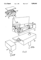
- FIG. 7 shows a cross section through the modular metering system of FIG. 6.
- FIG. 1 diagramatically represents the concept of a microbeam flow sensor.
- Cantilevered beams 4 and 5 are of differing length and thickness and these deflect when subjected to a flow of fluid.
- the longer beam 4 is less stiff and is used to measure low fluid velocities and the shorter, stiffer beam is used to measure higher velocities.
- a number of such cantilevers of varying stiffness may be used.
- the deflection of any one of the beams depends on the fluid velocity and density, the shape of the beam and the elastic modulus of the beam material. Assuming the shape and elastic modulus of the beam remain unchanged, the deflection of the beam can be related to the flow by the following expression:
- ⁇ is deflection of beam tip
- ⁇ is fluid density
- v is fluid velocity
- the output (OP.sub. ⁇ c) of the microchip flow sensor is given by the expression
- the mass flowrate (M) of the fluid is proportional to the product of fluid density and velocity
- ⁇ the fluid density
- FIG. 2 represents a system in which the microbeam flow sensor is used in conjunction with a density transducer, which enables the mass flow rate to be calculated.
- a suitable density transducer is described in copending United Kingdom patent application No. 8720355 filed Aug. 28, 1987 (Agent's Reference PQ 11993), which corresponds to U.S. application Ser. No. 237,808 filed Aug. 29, 1988 issuing as U.S. Pat. No. 4,890,480 on Jan. 2, 1990.
- This is based on a vibrating cantilever beam.
- the effective mass of a vibrating body is made up of the beam itself and a mass of the fluid around the beam.
- the amplitude of vibration of the beam depends on the effective mass and, because the mass of the beam is constant, any change in amplitude can be related to a change in fluid density.
- the beam may be caused to vibrate at a particular amplitude, and any change in the amount of energy required to keep the beam vibrating at that amplitude reflects the density of the surrounding fluid.
- the frequency may be monitored, and changes in frequency due to the surrounding fluid could be detected.
- the energy required to keep the beam vibrating at a particular frequency could be monitored.
- fluid flow is in the direction shown by the arrow 6, and a density transducer 7 and microbeam flow sensor 8 are located as shown, the density transducer being positioned in a region of substantially stationary fluid.
- At least two cantilevered beams are used; one to monitor relatively low flow rates, in the range 3.75 to 75 cm 3 s -1 and the other to monitor higher flow rates in the range 75 cm 3 s -1 to 1500 cm 3 s -1 .
- Each beam can be designed to measure over a 60:1 flowrange and in that case there will be an overlap range from approximately 22.5 to 225 cm 3 s -1 .
- FIGS. 3A and 3B show how small amounts of contamination, whether of a particulate nature 10 (as in FIG. 3A), or in the nature of a film 11 (as in FIG. 3B), affect the streamlines around the beam 9, giving a narrow wake 12 as opposed to the wide wake 13 in the uncontaminated case, and hence affect the drag forces on the beam. This, in turn, will affect the amount of deflection of the beam for a given flow velocity and hence also the accuracy of measurements made using the beam.
- the primary flow sensing element in the microbeam flow sensor is analogue in nature, in that the flow is inferred from the electrical measurement of the deflection of the cantilevered beams.
- Such analogue electronic systems tend to drift with time.
- the deflection of the beam is inferred from electrical capacitance measurement.
- the capacitance measurement will not only depend on the distance between the capacitor plates (i.e. the beam deflection), but also on the dielectric constant of fluid (e.g. gas) between the plates. If the fluid composition varies with time this could cause a change of dielectric constant and the evaluation of beam deflection, and hence the measured flowrate, would then be in error.
- the inventors have found ways of enabling a meter based on the microbeam flow sensor to "condition monitor” itself, and to recalibrate itself to counter effects of contamination and possible drift in meter accuracy and maintain accuracy over a 20 year period at least.
- An in-line filter may be incorporated in a metering system upstream of the meter, to avoid gross contamination of the cantilever beams in the microbeam flow sensor and the density transducer.
- This filter may be designed to remove particles greater than 10 ⁇ m in diameter and a 5 ⁇ m filter would be particularly desirable.
- a practical microbeam flow sensor could have three similar and preferably identical cantilevered beams to measure high flow rates and three similar and preferably identical, but more flexible, beams to measure the low flowrates.
- the contamination of any one beam can be isolated by comparing its output with those of the other two similar beams.
- the contamination of two of three similar beams can be monitored by comparing the output of all six beams in the overlap range.
- the beams can be considered in pairs, each pair consisting of a high flow and a low flow beam whose capacitances are connected in parallel. Contamination of any pair can be isolated by a voting procedure which compares the outputs of all three pairs.
- voting procedures can eliminate the effects of particulate contamination on the accuracy of the metering system, but if all three of a set of beams or, any two pairs of beams, were to become contaminated, recalibration would be necessary. Recalibration would also be necessary in the case of film contamination and changes in the dielectric constant of the metered fluid.
- a reference beam may be incorporated on the substrate of the microbeam flow sensor.
- the beam has fixed capacitance plates which will not vary with flow rate and so any change in capacitance of this beam would be due to a change of dielectric constant.
- a suitable fluidic flowmeter is described in copending European patent application No. 87305530.5, now publication No. 0,251,627 and corresponding to U.S. application Ser. No. 66,426 filed June 26, 1987 and issuing on June 13, 1989 as U.S. Pat. No. 4,838,091, and having the same assignee as the instant application.
- a fluidic flowmeter may be amalgamated with a vortex meter.
- FIG. 4 represents a fluid meter comprising a density transducer 14, a microbeam flow sensor 15 and a fluidic flowmeter 16.
- the fluidic meter has flow passages having larger dimensions than those of the flow sensor and density transducer. The accuracy of the fluidic meter is therefore much less affected by contamination than the microchip flow sensor. Also, the output of the fluidic meter is digital in nature (the frequency of the output is proportional to gas velocity) and is less prone to drift than that of sensors 14 and 15.
- the fluidic meter alone is not suitable for measuring flow rates at the lower end of the range which the present system is required to monitor.
- the last measured output value (which is dependent on velocity) can be stored by a computing circuit and this value can be used for calibration purposes until a measurable flow rate is again monitored and the stored value can be updated.
- FIG. 4 shows how the outputs DT of the density transducer and ⁇ c of the microchip sensor, related to ⁇ DT and ( ⁇ v 2 ).sub. ⁇ c respectively, can be used to recalibrate the meter.
- Monitoring and calibration logic can be performed by processing circuits shown generally at 17, 18, 19 and 20.
- the frequency of oscillation of the jet within the fluidic meter is believed to be directly proportional to the fluid velocity (v F ) which issues from an inlet nozzle 21.
- v F fluid velocity
- the fluid meter may for reasons of economy desirably include three microchips, each including a number of cantilever microbeams of varying stiffnesses as sensors, each set of microbeams being respectively arranged for use as a flow sensor, a density sensor and a fluidic frequency sensor.
- the fluidic frequency sensor beam could be engineered to be bi-directional.
- the invention is generally directed at calibration of a meter by comparing measurements from at least two metering or sensing devices and is particularly applicable when one of the devices is able to monitor lower flow rates.
- Silicon chip/microbeam technology which is applicable to this invention, is advantageous in terms of large turndown ratio, low cost, small size and low power consumption.
- a readout may be given in terms of mass flow or volume.
- the fluidic principle used in the fluidic flowmeter gives the advantages of digital output, simplicity of construction, tolerance of particulate contamination and no moving parts.
- the meter is described generally in relation to metering of fluids (liquids or gases), in general , it is particularly, though not exclusively, applicable for use in domestic gas metering.
- a fluid meter as herein described may be incorporated in a fluid metering system suitable for monitoring a fluid supply, particularly a domestic gas supply, and such a fluid metering system may also include an in-line filter, and a flow regulator. Other components, for example a thermal cut-off valve and a manual stop cock may also be included in the system, as appropriate.
- a meter in accordance with the present invention may be incorporated in the main flow channel or preferably in a bypass channel of the system to carry out measurements.
- a precisely known percentage of the total flow passes along the bypass so that measurements made in the bypass channel can be related to the total flow.
- a metering system which may include a meter according to the present invention is the subject of copending United Kingdom patent application No. (Agent's Reference PQ 54,272A) but it is also described here so that it will be clear how the present meter may be incorporated in such a system.
- FIG. 5 represents diagramatically the flow channels through one example of such a fluid metering system, fluid being routed, via an in-line filter 24, along a main flow channel 25 and along a by-pass channel 26 which, as will be described hereinafter, incorporates a fluid meter in accordance with the present invention. 10% of the flow is diverted through the bypass and the inline filter is incorporated in order to avoid gross contamination of the flow channels.
- FIG. 6 shows a perspective view of a modular metering installation suitable for use in a domestic gas supply
- FIG. 7 shows a cross-sectional view through the metering installation.
- the installation comprises a number of modular components which are arranged and assembled in a suitable casing.
- a control valve referenced generally at 27 includes a thermal cut-off valve, an example of which is the subject of our copending United Kingdom patent application No. 8720358 (Agent's Reference PQ 54,276), now publication No. 2,209,202 and which is also described in brief hereinafter.
- the control valve also includes a stop cock which is the subject of our copending United Kingdom patent application No. 8720357 filed Aug. 26, 1987 (Agent's Reference PQ 54,276A) and which is also described in brief hereinafter.
- This application corresponds to U.S. application Ser. No. 236,879 filed 8/26/1988, now U.S. Pat. No. 4,938,053.
- the stop cock has a rotatable plug in cooperation with a body, the plug having a fluid passage extending through it. Rotation of the plug allows control of fluid flow, and sealing of the stop cock plug to the body is assisted by resilient means such as a circlip which compresses the plug against sealing rings such as "0" ring seals.
- the thermal cut-off valve effects automatic shut-off of fluid flow in response to an ambient temperature greater than a predetermined value. This can be such that the fluid flow is shut off in a fire situation.
- the valve includes a component which undergoes a dimensional change if the ambient temperature exceeds the predetermined value and the dimensional change may be irreversible.
- the component may be made of memory metal, for example a shape memory effect spring which undergoes an irreversible expansion if the ambient temperature exceeds the predetermined value.
- An in-line regulator referenced at 28 may be of the type well known in the art which responds to the inlet pressure, at the outlet of control valve 27, to produce a substantially stable operating pressure within the system.
- Filter 29 is located between the control valve 27 and the inlet to the regulator 28.
- a fluid flow metering unit referenced generally at 30 comprises a main channel 31 including a throated section or venturi 32 and a bypass channel 33 which, in this example, incorporates a fluid meter in accordance with the invention.
- fluid enters an inlet 34 and passes successively through control valve 27, regulator 28 and into the metering unit 30.
- 10% of the total fluid flows through the bypass channel 33 and 90% flows along the part of the main channel indicated by 35.
- the main channel has a venturi 32 and fluid is accelerated through the venturi to draw in the flow from the bypass by a suction effect.
- the 10% recovered from the bypass and the expansion of fluid on the downstream side of the venturi gives a pressure drop across the whole metering unit which is significantly less than that across the bypass. For example, a differential pressure of at least two times that allowed across the complete metering unit can be generated across the bypass.
- This greater differential pressure allows a much smaller fluidic meter to be used in the bypass which in turn gives a much higher frequency output.
- the metering unit will therefore be more sensitive when measuring unsteady domestic gas flowrates, for example.
- the pressure drop across the whole metering unit is typically less than 2 millibars.
- the fluid meter 36 located in the bypass channel is a fluid meter according to the present invention, including a density transducer 37, a microbeam flow sensor 38 and a fluidic flowmeter 39 together with associated recalibration circuitry which may be contained within the installation or located externally.
- the density transducer 37 is located in a dead zone in the bypass, containing substantially stationary fluid, and is surrounded by a fine filter 40 (e.g. a 3 ⁇ m filter) so that the fluid around it is substantially stationary.
- An air foil 41 (which can be seen in FIG. 6) increases the velocity of the fluid (typically to greater than 20 cm/s) so that the beam technology works more effectively.
- the fluidic flowmeter illustrated has 90° bends in the outlet paths indicated by 42 which return the fluid to the main channel.
- the venturi shown in FIGS. 6 and 7 may be secured in position by a web.
- Electronic circuitry and batteries can be included in the meter casing 43, and sealed so there are no bare contacts.
- ⁇ O ⁇ ring seals may be used to prevent fluid leaks (this is especially important in the case of inflammable liquids and gases), and the casing can be vented by holes or by the porosity of a plastics material used to construct the casing.
- the meter can be read through a window, by remote metering or using a suitable Mainsborne system.
- Locating the microbeam flow sensor and density transducer in the bypass channel further protects them from contamination.
- the main flow channel will be self cleaning, having a flat bottom to avoid debris build-up.
- the change in flow direction for the bypass causes most of the particulate matter (i.e. particles >10 ⁇ m in diameter) to pass directly through the main channel and, in the case of domestic gas metering, to the burners.
- a gravity filter 44 positioned at the inlet of metering unit 30 which reduces fluid velocity and causes any large fluid-borne debris to drop back into the main flow.
- a diffuser consisting of a series of vanes may be placed at the inlet to the metering unit.
- the diffuser can replace the gravity filter as a means to cause particles >125 ⁇ m (for example) to fall out of the flow so that the jet does not carry debris.
- the modular construction can be thought of as two blocks--a fluid flow metering unit block and a block comprising the control valve and regulator.
- a domestic gas meter installation of this construction can be designed to replace two housebricks, the installation being approximately 1/6 the size of meter boxes currently used. Including inlet and outlet pipes, the total volume of the installation could correspond to the volume of three housebricks.
Abstract
Description
δαρv.sup.2
OP.sub.μc αρv.sup.2 (1)
Mαρv (2)
Claims (8)
Applications Claiming Priority (2)
| Application Number | Priority Date | Filing Date | Title |
|---|---|---|---|
| GB8720356 | 1987-08-28 | ||
| GB878720356A GB8720356D0 (en) | 1987-08-28 | 1987-08-28 | Fluid meter |
Publications (1)
| Publication Number | Publication Date |
|---|---|
| US5003810A true US5003810A (en) | 1991-04-02 |
Family
ID=10622981
Family Applications (1)
| Application Number | Title | Priority Date | Filing Date |
|---|---|---|---|
| US07/237,389 Expired - Fee Related US5003810A (en) | 1987-08-28 | 1988-08-26 | Fluid meter |
Country Status (6)
| Country | Link |
|---|---|
| US (1) | US5003810A (en) |
| EP (1) | EP0306193A1 (en) |
| JP (1) | JPH01206218A (en) |
| AU (1) | AU610227B2 (en) |
| CA (1) | CA1325477C (en) |
| GB (1) | GB8720356D0 (en) |
Cited By (37)
| Publication number | Priority date | Publication date | Assignee | Title |
|---|---|---|---|---|
| US5157974A (en) * | 1990-06-27 | 1992-10-27 | Tokyo Gas Company, Limited | Fluidic flowmeter |
| US5257538A (en) * | 1989-04-12 | 1993-11-02 | Siemens Aktiengesellschaft | Gas consumption measuring device |
| US5502659A (en) * | 1994-06-06 | 1996-03-26 | Endress+Hauser, Inc. | Method and apparatus for calibrating moisture sensors |
| US5677476A (en) * | 1996-02-06 | 1997-10-14 | Endress + Hauser Conducta Gesellschaft Fuer Mess- Und Regeltechnik Mbh & Co. | Sensor and transmitter with multiple outputs |
| US5706273A (en) * | 1994-04-29 | 1998-01-06 | Electronic Warfare Associates, Inc. | Liquid registration and control system having networked functional modules |
| US5911238A (en) * | 1996-10-04 | 1999-06-15 | Emerson Electric Co. | Thermal mass flowmeter and mass flow controller, flowmetering system and method |
| US5944048A (en) * | 1996-10-04 | 1999-08-31 | Emerson Electric Co. | Method and apparatus for detecting and controlling mass flow |
| US5959219A (en) * | 1997-07-28 | 1999-09-28 | Saunders; David N. | Capacitive gas flow sensor |
| US6092410A (en) * | 1998-02-20 | 2000-07-25 | Marconi Commerce Systems Inc. | Meter calibration and drift compensation device |
| US6119710A (en) * | 1999-05-26 | 2000-09-19 | Cyber Instrument Technologies Llc | Method for wide range gas flow system with real time flow measurement and correction |
| US6250132B1 (en) * | 1997-08-18 | 2001-06-26 | Metasensors, Inc. | Method and apparatus for real time gas analysis |
| US6286360B1 (en) | 1999-02-25 | 2001-09-11 | Metasensors, Inc. | Methods and apparatus for real time fluid analysis |
| US6310454B1 (en) | 1997-11-07 | 2001-10-30 | Robert L. Moran | Apparatus and control method for feeder system for flowable material |
| US6443174B2 (en) | 2000-07-08 | 2002-09-03 | Daniel T. Mudd | Fluid mass flow control valve and method of operation |
| US6508112B1 (en) | 2000-01-21 | 2003-01-21 | Dean Verhoeven | Tomographic spray momentum mapping system |
| US6539968B1 (en) | 2000-09-20 | 2003-04-01 | Fugasity Corporation | Fluid flow controller and method of operation |
| US6561218B2 (en) | 2000-07-25 | 2003-05-13 | Fugasity Corporation | Small internal volume fluid mass flow control apparatus |
| US20040069348A1 (en) * | 2002-06-28 | 2004-04-15 | Jacobs Steven D. | Valve calibration method and apparatus |
| US20050081622A1 (en) * | 2002-12-23 | 2005-04-21 | Laurent Demia | System for detecting the positioning of a measuring module on a fluid meter |
| US20050262943A1 (en) * | 2004-05-27 | 2005-12-01 | Glenn Claydon | Apparatus, methods, and systems to detect an analyte based on changes in a resonant frequency of a spring element |
| US20060057955A1 (en) * | 2002-12-03 | 2006-03-16 | Lg Electronics Inc. | Flow spreading mechanism |
| US20060150708A1 (en) * | 2002-09-12 | 2006-07-13 | Rudolf Bierl | Device and method for calibration of a mass flow sensor |
| WO2012052989A1 (en) * | 2010-10-19 | 2012-04-26 | Raphael Valves Industries (1975) Ltd. | An integrated ultrasonic flowmeter and hydraulic valve |
| US8966970B2 (en) | 2012-12-18 | 2015-03-03 | General Electric Company | Flow sensor assembly having a hybrid sensor response |
| US9170135B2 (en) * | 2012-10-30 | 2015-10-27 | Itron, Inc. | Module for gas flow measurements with a dual sensing assembly |
| US9222812B2 (en) | 2012-10-30 | 2015-12-29 | Itron, Inc. | Hybrid sensor system for gas flow measurements |
| US20170002778A1 (en) * | 2015-07-01 | 2017-01-05 | Yow Jung Enterprise Co., Ltd. | System and voltage type method for testing air flow meter |
| US20170003158A1 (en) * | 2015-07-01 | 2017-01-05 | Yow Jung Enterprise Co., Ltd. | Frequency test method of airflow machine |
| US9958302B2 (en) | 2011-08-20 | 2018-05-01 | Reno Technologies, Inc. | Flow control system, method, and apparatus |
| US10303189B2 (en) | 2016-06-30 | 2019-05-28 | Reno Technologies, Inc. | Flow control system, method, and apparatus |
| US10663337B2 (en) | 2016-12-30 | 2020-05-26 | Ichor Systems, Inc. | Apparatus for controlling flow and method of calibrating same |
| US10679880B2 (en) | 2016-09-27 | 2020-06-09 | Ichor Systems, Inc. | Method of achieving improved transient response in apparatus for controlling flow and system for accomplishing same |
| US10838437B2 (en) | 2018-02-22 | 2020-11-17 | Ichor Systems, Inc. | Apparatus for splitting flow of process gas and method of operating same |
| US11003198B2 (en) | 2011-08-20 | 2021-05-11 | Ichor Systems, Inc. | Controlled delivery of process gas using a remote pressure measurement device |
| US11144075B2 (en) | 2016-06-30 | 2021-10-12 | Ichor Systems, Inc. | Flow control system, method, and apparatus |
| US20220280963A1 (en) * | 2021-03-04 | 2022-09-08 | Stratec Se | Sensor for determining the oscillating frequency in a fluidic oscillating nozzle and a method using the sensor |
| US11899477B2 (en) | 2021-03-03 | 2024-02-13 | Ichor Systems, Inc. | Fluid flow control system comprising a manifold assembly |
Families Citing this family (14)
| Publication number | Priority date | Publication date | Assignee | Title |
|---|---|---|---|---|
| US4961348A (en) * | 1988-12-16 | 1990-10-09 | Ulrich Bonne | Flowmeter fluid composition correction |
| GB8908749D0 (en) * | 1989-04-18 | 1989-06-07 | Jeavons Engineering Ltd | Flowmeters |
| US5132917A (en) * | 1990-04-23 | 1992-07-21 | Shell Oil Company | Method and apparatus for the combined use of dual density measurements to achieve a fast and accurate density measurement in pneumatically transported solids |
| US5298886A (en) * | 1990-06-14 | 1994-03-29 | Tokyo Gas Company Limited | Fluidic flowmeter equipped with a micro flow sensor |
| GB9105699D0 (en) * | 1991-03-18 | 1991-05-01 | British Gas Plc | Supplying fluid |
| DE4339771C2 (en) * | 1993-11-23 | 1996-09-12 | Hiss Eckart | Electronic evaluation device |
| FR2748109B1 (en) * | 1996-04-30 | 1998-07-31 | Schlumberger Ind Sa | DEVICE FOR MEASURING THE FLOW OF A FLOWING FLOW WITH ELEMENT (S) MODIFYING THE SPEED PROFILE OF SAID FLOW |
| DE19619632A1 (en) * | 1996-05-15 | 1997-11-20 | S K I Schlegel & Kremer Indust | Measuring density of flowing fluid using at least two measuring points |
| FR2764373B1 (en) * | 1997-06-06 | 1999-08-13 | Schlumberger Ind Sa | REDUCED CONGESTION FLUID COUNTER |
| FR2770644B1 (en) * | 1997-11-04 | 1999-12-31 | Schlumberger Ind Sa | FLUID METER WITH IMPROVED COMPACITY |
| US6477900B2 (en) | 2001-01-08 | 2002-11-12 | Jet Sensor Ltd. | Fluidic gas metering system |
| DE10127261B4 (en) * | 2001-06-05 | 2005-02-10 | Erbe Elektromedizin Gmbh | Measuring device for the flow rate of a gas, in particular for use in plasma surgery |
| DE102005023115B4 (en) * | 2005-05-19 | 2010-03-11 | Technische Universität Darmstadt | A method of monitoring a fluid flow measurement and sensor system for a fluid flow measurement |
| DE102016011256A1 (en) | 2016-09-17 | 2018-03-22 | Diehl Metering Gmbh | Method for determining the flow of a flowing medium |
Citations (12)
| Publication number | Priority date | Publication date | Assignee | Title |
|---|---|---|---|---|
| US2805574A (en) * | 1952-09-22 | 1957-09-10 | Standard Oil Co | Wide range flow meter |
| US3219046A (en) * | 1960-08-25 | 1965-11-23 | Foxboro Co | Fluid ratio control |
| SU543285A1 (en) * | 1975-05-20 | 1979-10-05 | Октябрьский Филиал Всесоюзного Научно-Исследовательского И Проектно-Конструкторского Института Комплексной Автоматизации Нефтяной И Газовой Промышленности | Method of graduating and testing liquid flowmeters |
| US4475387A (en) * | 1983-03-23 | 1984-10-09 | Teledyne Industries, Inc. | High temperature mass flowmeter |
| GB2177204A (en) * | 1985-06-26 | 1987-01-14 | British Gas Corp | Measurement of fluid flows |
| US4644474A (en) * | 1985-01-14 | 1987-02-17 | Ford Motor Company | Hybrid airflow measurement |
| EP0239703A1 (en) * | 1986-01-07 | 1987-10-07 | THORN EMI plc | Force-sensitive flow sensor |
| GB2209200A (en) * | 1987-08-28 | 1989-05-04 | Thorn Emi Flow Measurement Ltd | Thermal cut-off valve |
| US4838091A (en) * | 1986-06-27 | 1989-06-13 | Thorn Emi Flow Measurement Limited | Fludic oscillator flowmeters |
| US4890480A (en) * | 1987-08-28 | 1990-01-02 | Thorn Emi Plc | Relating to devices for measuring fluid density |
| US4911006A (en) * | 1986-10-03 | 1990-03-27 | Micro Motion Incorporated | Custody transfer meter |
| US4938053A (en) * | 1987-08-28 | 1990-07-03 | Thorm EMI Flow Measurement Limited | Fluid metering system |
Family Cites Families (4)
| Publication number | Priority date | Publication date | Assignee | Title |
|---|---|---|---|---|
| GB1554408A (en) * | 1975-10-04 | 1979-10-17 | Lucas Industries Ltd | Apparatus for measuring mass flow of fluids |
| US3992939A (en) * | 1976-02-11 | 1976-11-23 | International Telephone And Telegraph Corporation | Apparatus for producing a mass flow rate signal with or without a density signal |
| GB2085597B (en) * | 1980-10-17 | 1985-01-30 | Redland Automation Ltd | Method and apparatus for detemining the mass flow of a fluid |
| US4524616A (en) * | 1983-09-02 | 1985-06-25 | Tylan Corporation | Adjustable laminar flow bypass |
-
1987
- 1987-08-28 GB GB878720356A patent/GB8720356D0/en active Pending
-
1988
- 1988-08-22 EP EP88307754A patent/EP0306193A1/en not_active Withdrawn
- 1988-08-26 US US07/237,389 patent/US5003810A/en not_active Expired - Fee Related
- 1988-08-26 AU AU21556/88A patent/AU610227B2/en not_active Ceased
- 1988-08-26 CA CA000575826A patent/CA1325477C/en not_active Expired - Fee Related
- 1988-08-29 JP JP63212649A patent/JPH01206218A/en active Pending
Patent Citations (12)
| Publication number | Priority date | Publication date | Assignee | Title |
|---|---|---|---|---|
| US2805574A (en) * | 1952-09-22 | 1957-09-10 | Standard Oil Co | Wide range flow meter |
| US3219046A (en) * | 1960-08-25 | 1965-11-23 | Foxboro Co | Fluid ratio control |
| SU543285A1 (en) * | 1975-05-20 | 1979-10-05 | Октябрьский Филиал Всесоюзного Научно-Исследовательского И Проектно-Конструкторского Института Комплексной Автоматизации Нефтяной И Газовой Промышленности | Method of graduating and testing liquid flowmeters |
| US4475387A (en) * | 1983-03-23 | 1984-10-09 | Teledyne Industries, Inc. | High temperature mass flowmeter |
| US4644474A (en) * | 1985-01-14 | 1987-02-17 | Ford Motor Company | Hybrid airflow measurement |
| GB2177204A (en) * | 1985-06-26 | 1987-01-14 | British Gas Corp | Measurement of fluid flows |
| EP0239703A1 (en) * | 1986-01-07 | 1987-10-07 | THORN EMI plc | Force-sensitive flow sensor |
| US4838091A (en) * | 1986-06-27 | 1989-06-13 | Thorn Emi Flow Measurement Limited | Fludic oscillator flowmeters |
| US4911006A (en) * | 1986-10-03 | 1990-03-27 | Micro Motion Incorporated | Custody transfer meter |
| GB2209200A (en) * | 1987-08-28 | 1989-05-04 | Thorn Emi Flow Measurement Ltd | Thermal cut-off valve |
| US4890480A (en) * | 1987-08-28 | 1990-01-02 | Thorn Emi Plc | Relating to devices for measuring fluid density |
| US4938053A (en) * | 1987-08-28 | 1990-07-03 | Thorm EMI Flow Measurement Limited | Fluid metering system |
Cited By (47)
| Publication number | Priority date | Publication date | Assignee | Title |
|---|---|---|---|---|
| US5257538A (en) * | 1989-04-12 | 1993-11-02 | Siemens Aktiengesellschaft | Gas consumption measuring device |
| US5157974A (en) * | 1990-06-27 | 1992-10-27 | Tokyo Gas Company, Limited | Fluidic flowmeter |
| US5706273A (en) * | 1994-04-29 | 1998-01-06 | Electronic Warfare Associates, Inc. | Liquid registration and control system having networked functional modules |
| US5502659A (en) * | 1994-06-06 | 1996-03-26 | Endress+Hauser, Inc. | Method and apparatus for calibrating moisture sensors |
| US5677476A (en) * | 1996-02-06 | 1997-10-14 | Endress + Hauser Conducta Gesellschaft Fuer Mess- Und Regeltechnik Mbh & Co. | Sensor and transmitter with multiple outputs |
| US5944048A (en) * | 1996-10-04 | 1999-08-31 | Emerson Electric Co. | Method and apparatus for detecting and controlling mass flow |
| US5975126A (en) * | 1996-10-04 | 1999-11-02 | Emerson Electric Co. | Method and apparatus for detecting and controlling mass flow |
| US5911238A (en) * | 1996-10-04 | 1999-06-15 | Emerson Electric Co. | Thermal mass flowmeter and mass flow controller, flowmetering system and method |
| US5959219A (en) * | 1997-07-28 | 1999-09-28 | Saunders; David N. | Capacitive gas flow sensor |
| US6250132B1 (en) * | 1997-08-18 | 2001-06-26 | Metasensors, Inc. | Method and apparatus for real time gas analysis |
| US6310454B1 (en) | 1997-11-07 | 2001-10-30 | Robert L. Moran | Apparatus and control method for feeder system for flowable material |
| US6092410A (en) * | 1998-02-20 | 2000-07-25 | Marconi Commerce Systems Inc. | Meter calibration and drift compensation device |
| US6286360B1 (en) | 1999-02-25 | 2001-09-11 | Metasensors, Inc. | Methods and apparatus for real time fluid analysis |
| US6119710A (en) * | 1999-05-26 | 2000-09-19 | Cyber Instrument Technologies Llc | Method for wide range gas flow system with real time flow measurement and correction |
| US6216726B1 (en) | 1999-05-26 | 2001-04-17 | Cyber Instrument Technologies Llc | Wide range gas flow system with real time flow measurement and correction |
| US6508112B1 (en) | 2000-01-21 | 2003-01-21 | Dean Verhoeven | Tomographic spray momentum mapping system |
| US6443174B2 (en) | 2000-07-08 | 2002-09-03 | Daniel T. Mudd | Fluid mass flow control valve and method of operation |
| US6561218B2 (en) | 2000-07-25 | 2003-05-13 | Fugasity Corporation | Small internal volume fluid mass flow control apparatus |
| US6539968B1 (en) | 2000-09-20 | 2003-04-01 | Fugasity Corporation | Fluid flow controller and method of operation |
| US20040069348A1 (en) * | 2002-06-28 | 2004-04-15 | Jacobs Steven D. | Valve calibration method and apparatus |
| US7543595B2 (en) * | 2002-06-28 | 2009-06-09 | Siemens Building Technologies, Inc. | Valve calibration method and apparatus |
| US7461537B2 (en) * | 2002-09-12 | 2008-12-09 | Siemens Aktiengesellschaft | Device and method for calibration of a mass flow sensor |
| US20060150708A1 (en) * | 2002-09-12 | 2006-07-13 | Rudolf Bierl | Device and method for calibration of a mass flow sensor |
| US20060057955A1 (en) * | 2002-12-03 | 2006-03-16 | Lg Electronics Inc. | Flow spreading mechanism |
| US7510471B2 (en) * | 2002-12-03 | 2009-03-31 | Lg Electronics Inc. | Flow spreading mechanism |
| US20050081622A1 (en) * | 2002-12-23 | 2005-04-21 | Laurent Demia | System for detecting the positioning of a measuring module on a fluid meter |
| US20050262943A1 (en) * | 2004-05-27 | 2005-12-01 | Glenn Claydon | Apparatus, methods, and systems to detect an analyte based on changes in a resonant frequency of a spring element |
| WO2012052989A1 (en) * | 2010-10-19 | 2012-04-26 | Raphael Valves Industries (1975) Ltd. | An integrated ultrasonic flowmeter and hydraulic valve |
| US10782165B2 (en) | 2011-08-20 | 2020-09-22 | Ichor Systems, Inc. | Flow control system, method, and apparatus |
| US9958302B2 (en) | 2011-08-20 | 2018-05-01 | Reno Technologies, Inc. | Flow control system, method, and apparatus |
| US11003198B2 (en) | 2011-08-20 | 2021-05-11 | Ichor Systems, Inc. | Controlled delivery of process gas using a remote pressure measurement device |
| US9222812B2 (en) | 2012-10-30 | 2015-12-29 | Itron, Inc. | Hybrid sensor system for gas flow measurements |
| US9170135B2 (en) * | 2012-10-30 | 2015-10-27 | Itron, Inc. | Module for gas flow measurements with a dual sensing assembly |
| US8966970B2 (en) | 2012-12-18 | 2015-03-03 | General Electric Company | Flow sensor assembly having a hybrid sensor response |
| US20170321639A1 (en) * | 2015-07-01 | 2017-11-09 | Yow Jung Enterprise Co., Ltd. | Voltage type method for testing air flow meter |
| US20170003158A1 (en) * | 2015-07-01 | 2017-01-05 | Yow Jung Enterprise Co., Ltd. | Frequency test method of airflow machine |
| US20170002778A1 (en) * | 2015-07-01 | 2017-01-05 | Yow Jung Enterprise Co., Ltd. | System and voltage type method for testing air flow meter |
| US10303189B2 (en) | 2016-06-30 | 2019-05-28 | Reno Technologies, Inc. | Flow control system, method, and apparatus |
| US10782710B2 (en) | 2016-06-30 | 2020-09-22 | Ichor Systems, Inc. | Flow control system, method, and apparatus |
| US11144075B2 (en) | 2016-06-30 | 2021-10-12 | Ichor Systems, Inc. | Flow control system, method, and apparatus |
| US11815920B2 (en) | 2016-06-30 | 2023-11-14 | Ichor Systems, Inc. | Flow control system, method, and apparatus |
| US10679880B2 (en) | 2016-09-27 | 2020-06-09 | Ichor Systems, Inc. | Method of achieving improved transient response in apparatus for controlling flow and system for accomplishing same |
| US11424148B2 (en) | 2016-09-27 | 2022-08-23 | Ichor Systems, Inc. | Method of achieving improved transient response in apparatus for controlling flow and system for accomplishing same |
| US10663337B2 (en) | 2016-12-30 | 2020-05-26 | Ichor Systems, Inc. | Apparatus for controlling flow and method of calibrating same |
| US10838437B2 (en) | 2018-02-22 | 2020-11-17 | Ichor Systems, Inc. | Apparatus for splitting flow of process gas and method of operating same |
| US11899477B2 (en) | 2021-03-03 | 2024-02-13 | Ichor Systems, Inc. | Fluid flow control system comprising a manifold assembly |
| US20220280963A1 (en) * | 2021-03-04 | 2022-09-08 | Stratec Se | Sensor for determining the oscillating frequency in a fluidic oscillating nozzle and a method using the sensor |
Also Published As
| Publication number | Publication date |
|---|---|
| CA1325477C (en) | 1993-12-21 |
| AU610227B2 (en) | 1991-05-16 |
| JPH01206218A (en) | 1989-08-18 |
| GB8720356D0 (en) | 1987-10-07 |
| EP0306193A1 (en) | 1989-03-08 |
| AU2155688A (en) | 1989-03-02 |
Similar Documents
| Publication | Publication Date | Title |
|---|---|---|
| US5003810A (en) | Fluid meter | |
| US4938053A (en) | Fluid metering system | |
| US4116060A (en) | Mass flow sensor and method | |
| US7258024B2 (en) | Simplified fluid property measurement | |
| US4523477A (en) | Planar-measuring vortex-shedding mass flowmeter | |
| US5939643A (en) | Vortex flow sensor with a cylindrical bluff body having roughned surface | |
| US20110022335A1 (en) | Real-time non-stationary flowmeter | |
| US4142401A (en) | Gage | |
| US10066976B2 (en) | Vortex flow meter with micromachined sensing elements | |
| CA1240854A (en) | Reaction mass flowmeter | |
| US5537860A (en) | Fluid sensor including substantially linear flow resistor | |
| US3530714A (en) | Target flowmeter | |
| GB2161941A (en) | Mass flow meter | |
| Baker et al. | The measurement of gas flow part ii | |
| Wright | The Coanda meter-a fluidic digital gas flowmeter | |
| US4085615A (en) | Linear flowmeter | |
| GB2177204A (en) | Measurement of fluid flows | |
| JPS58189518A (en) | Mass flowmeter | |
| JP2002538451A (en) | Gas meter | |
| US5959219A (en) | Capacitive gas flow sensor | |
| Sakai et al. | The fluidic flowmeter—A gas flowmeter based on fluidic dynamic oscillation | |
| US11815524B2 (en) | Volume fraction meter for multiphase fluid flow | |
| JPH0353124A (en) | Flow meter | |
| RU2071036C1 (en) | Electronic meter of liquid and gas flows | |
| JP2735678B2 (en) | Flow sensor type flow meter |
Legal Events
| Date | Code | Title | Description |
|---|---|---|---|
| AS | Assignment |
Owner name: THORN EMI FLOW MEASUREMENT LIMITED, P.O. BOX 3, TA Free format text: ASSIGNMENT OF ASSIGNORS INTEREST.;ASSIGNORS:JEPSON, PETER;TOFIELD, GRAHAM M.;REEL/FRAME:004970/0637 Effective date: 19880823 Owner name: THORN EMI FLOW MEASUREMENT LIMITED, ENGLAND Free format text: ASSIGNMENT OF ASSIGNORS INTEREST;ASSIGNORS:JEPSON, PETER;TOFIELD, GRAHAM M.;REEL/FRAME:004970/0637 Effective date: 19880823 |
|
| FEPP | Fee payment procedure |
Free format text: PAYOR NUMBER ASSIGNED (ORIGINAL EVENT CODE: ASPN); ENTITY STATUS OF PATENT OWNER: LARGE ENTITY |
|
| AS | Assignment |
Owner name: SCHLUMBERGER INDUSTRIES LIMITED, ENGLAND Free format text: ASSIGNMENT OF ASSIGNORS INTEREST;ASSIGNOR:SCHLUMBERGER FLOW MEASUREMENT LIMITED;REEL/FRAME:007274/0001 Effective date: 19930131 |
|
| FPAY | Fee payment |
Year of fee payment: 4 |
|
| SULP | Surcharge for late payment | ||
| AS | Assignment |
Owner name: SCHLUMBERGER FLOW MEASUREMENT LIMITED, ENGLAND Free format text: CHANGE OF NAME;ASSIGNOR:THORN EMI FLOW MEASUREMENT LIMITED;REEL/FRAME:007274/0004 Effective date: 19890907 |
|
| FPAY | Fee payment |
Year of fee payment: 8 |
|
| SULP | Surcharge for late payment | ||
| REMI | Maintenance fee reminder mailed | ||
| LAPS | Lapse for failure to pay maintenance fees | ||
| FP | Lapsed due to failure to pay maintenance fee |
Effective date: 20030402 |
|
| STCH | Information on status: patent discontinuation |
Free format text: PATENT EXPIRED DUE TO NONPAYMENT OF MAINTENANCE FEES UNDER 37 CFR 1.362 |