US5022366A - Rotary engine with dual spark plugs and fuel injectors - Google Patents
Rotary engine with dual spark plugs and fuel injectors Download PDFInfo
- Publication number
- US5022366A US5022366A US07/408,572 US40857289A US5022366A US 5022366 A US5022366 A US 5022366A US 40857289 A US40857289 A US 40857289A US 5022366 A US5022366 A US 5022366A
- Authority
- US
- United States
- Prior art keywords
- fuel
- injector
- main
- spark plug
- pilot
- Prior art date
- Legal status (The legal status is an assumption and is not a legal conclusion. Google has not performed a legal analysis and makes no representation as to the accuracy of the status listed.)
- Expired - Fee Related
Links
Images

Classifications
-
- F—MECHANICAL ENGINEERING; LIGHTING; HEATING; WEAPONS; BLASTING
- F02—COMBUSTION ENGINES; HOT-GAS OR COMBUSTION-PRODUCT ENGINE PLANTS
- F02B—INTERNAL-COMBUSTION PISTON ENGINES; COMBUSTION ENGINES IN GENERAL
- F02B53/00—Internal-combustion aspects of rotary-piston or oscillating-piston engines
- F02B53/10—Fuel supply; Introducing fuel to combustion space
-
- F—MECHANICAL ENGINEERING; LIGHTING; HEATING; WEAPONS; BLASTING
- F02—COMBUSTION ENGINES; HOT-GAS OR COMBUSTION-PRODUCT ENGINE PLANTS
- F02B—INTERNAL-COMBUSTION PISTON ENGINES; COMBUSTION ENGINES IN GENERAL
- F02B53/00—Internal-combustion aspects of rotary-piston or oscillating-piston engines
- F02B53/12—Ignition
-
- F—MECHANICAL ENGINEERING; LIGHTING; HEATING; WEAPONS; BLASTING
- F02—COMBUSTION ENGINES; HOT-GAS OR COMBUSTION-PRODUCT ENGINE PLANTS
- F02B—INTERNAL-COMBUSTION PISTON ENGINES; COMBUSTION ENGINES IN GENERAL
- F02B1/00—Engines characterised by fuel-air mixture compression
- F02B1/02—Engines characterised by fuel-air mixture compression with positive ignition
- F02B1/04—Engines characterised by fuel-air mixture compression with positive ignition with fuel-air mixture admission into cylinder
-
- F—MECHANICAL ENGINEERING; LIGHTING; HEATING; WEAPONS; BLASTING
- F02—COMBUSTION ENGINES; HOT-GAS OR COMBUSTION-PRODUCT ENGINE PLANTS
- F02B—INTERNAL-COMBUSTION PISTON ENGINES; COMBUSTION ENGINES IN GENERAL
- F02B53/00—Internal-combustion aspects of rotary-piston or oscillating-piston engines
- F02B2053/005—Wankel engines
-
- Y—GENERAL TAGGING OF NEW TECHNOLOGICAL DEVELOPMENTS; GENERAL TAGGING OF CROSS-SECTIONAL TECHNOLOGIES SPANNING OVER SEVERAL SECTIONS OF THE IPC; TECHNICAL SUBJECTS COVERED BY FORMER USPC CROSS-REFERENCE ART COLLECTIONS [XRACs] AND DIGESTS
- Y02—TECHNOLOGIES OR APPLICATIONS FOR MITIGATION OR ADAPTATION AGAINST CLIMATE CHANGE
- Y02T—CLIMATE CHANGE MITIGATION TECHNOLOGIES RELATED TO TRANSPORTATION
- Y02T10/00—Road transport of goods or passengers
- Y02T10/10—Internal combustion engine [ICE] based vehicles
- Y02T10/12—Improving ICE efficiencies
Definitions
- the invention relates to rotary internal combustion engines of the type disclosed in prior U.S. Pat. No. 2,988,065 granted on June 13, 1961 to Wankel et al, and particularly to such an engine designed for operation as a stratified charge engine and employing two high pressure fuel injection nozzles, as disclosed in U.S. Pat. No. 4,083,329 granted on 11 April 1978 to Meyers.
- This system includes a pilot fuel injector, a main fuel injector and a single spark plug which ignites fuel from the pilot injector.
- the burning pilot fuel then ignites the fuel/air mixture in the rotating combustion pocket injected by the main injector. It is believed that the presence of a richer-than-flammable fuel/air mixture in the center of the pocket retards the flame propagation from the leading portion of the pocket to the trailing portion, even though a flammable fuel/air mixture is available on the trailing side of the richer-than-flammable mixture. This may slow down the burning process and reduce combustion efficiency.
- An object of the present invention is to provide a stratified charge rotary combustion engine with improved combustion efficiency.
- a rotary internal combustion engine includes main and pilot fuel injectors.
- the main fuel injector is positioned between the two spark plugs and has a central axis which is inclined with respect to the plane of rotor rotation.
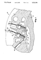
- FIG. 1 is a schematic partial transverse sectional view of a top-dead-center region of a rotary combustion engine embodying the invention
- FIG. 2 is a sectional view taken along lines 2--2 of FIG. 1.
- a rotating combustion engine 10 comprises an outer body or housing consisting of two axially spaced end housings (not shown) and an intermediate or rotor housing 12, the housings being secured together to form the engine cavity therebetween.
- An inner body or rotor 18 is journaled for rotation within said housing cavity on an eccentric portion of a shaft (not shown) which extends coaxially through and is supported by bearings (not shown) in the end housings.
- the peripheral inner or running surface 24 of the intermediate housing 12 has a two-lobe profile which preferably is basically an epitrochoid, the two lobes joining at minor axis or junction 25.
- Each of the three working faces of the rotor 18 preferably is provided with a trough-like recess 19 therein.
- the engine 10 also includes suitable gearing (not shown) between the rotor 18 and the engine housing to control the relative rotation of the rotor.
- suitable gearing is conventional and preferably is similar to that illustrated in the aforementioned patent to Wankel et al.
- a pilot fuel injector 50 is mounted on the intermediate housing 12 adjacent to and downstream of the lobe junction 25.
- the pilot injector 50 has its fuel discharge end disposed in a recess 51 opening to the trochoidal surface 24 for discharging fuel into each working chamber after the air-intake charge within the chamber has been substantially compressed and combustion is about to be initiated.
- a first spark plug type igniter 52 is also mounted on the intermediate housing adjacent to the lobe junction 25 and adjacent to and upstream from the injector 50.
- the electrodes of the spark plug 52 are disposed adjacent to the discharge end of the injector 50 preferably so that the injector discharge end and the spark plug electrodes both open through the trochoidal surface 24 through the same common recess 51.
- the injector 50 and spark plug 52 preferably are disposed so that at least a portion of the fuel vapor produced by fuel spray discharged from the pilot injector passes in close proximity to the spark plug electrodes as the fuel leaves the pilot injector for ready ignition by the spark plug 52.
- a main fuel injector 60 is mounted on the intermediate housing 12 also adjacent to the lobe junction 25 but on the upstream side of the junction. As best seen in FIG. 2, the main injector 60 is inclined with respect to the plane of rotation of the rotor 18 by approximately 30 degrees. As in the case of the pilot injector 50, the main fuel injector 60 is arranged to initiate the discharge of its fuel into each working chamber 28 after the air charge in the chamber has been substantially compressed and combustion is about to be initiated in a timely manner relative to discharge of fuel from the pilot injector 50.
- each working chamber 28 discharge of fuel from the main injector 60 into each working chamber 28 may be initiated somewhat after fuel is discharged from the injector 50 whereas at high engine loads in order to provide time for fuel discharge from the main injector 60, the fuel discharge from this main injector can be initiated somewhat before fuel is discharged from the pilot injector 50.
- the combustion flame resulting from the ignition by the spark plug 52 of the fuel discharging from the pilot injector 50 into each working chamber 28 is effective to ignite the fuel discharged from the main injector 60 into the chamber.
- the burning fuel discharged by the pilot fuel injector 50 functions as a pilot flame to ignite the fuel discharged by the main injector 60.
- a second spark plug type ignition device 70 is positioned adjacent to and upstream of the main injector 60 so that the main injector is located generally between the first and second spark plugs 52 and 70.
- the pilot injector 50 and the spark plugs 52 and 70 are aligned with the plane of rotation of the rotor 18.
- an ignition circuit (not shown) for the spark plug 52 is arranged to fire the spark plug while fuel is discharging from the nozzle 50 into a working chamber 29 so that a portion of this fuel is ignited at the fuel injector 50 as it discharges from the injector and the burning of this initial portion of the fuel discharged from the injector 50 ignites the balance of the fuel discharging from the injector.
- the timing of the spark from the spark plug 52 is such that it fires during the period of discharge from the injector 50 into a working chamber 28 and preferably during the initial period of such discharge into each working chamber 28.
- the second spark plug 70 would be fired to ignite the flammable mixture on the trailing side of the minor axis, and upstream of the richer-than-flammable mixture (not shown) in the central region of the combustion pocket. It is predicted that this two-spark plug arrangement will better ignite the fuel/air mixture and improve the combustion efficiency.
Abstract
Description
Claims (2)
Priority Applications (4)
| Application Number | Priority Date | Filing Date | Title |
|---|---|---|---|
| US07/408,572 US5022366A (en) | 1989-09-18 | 1989-09-18 | Rotary engine with dual spark plugs and fuel injectors |
| CA002023473A CA2023473C (en) | 1989-09-18 | 1990-08-16 | Rotary engine with dual spark plugs |
| EP90116825A EP0418624A1 (en) | 1989-09-18 | 1990-09-01 | Rotary internal combustion engine |
| JP2248564A JPH03130532A (en) | 1989-09-18 | 1990-09-18 | Stratified fuel loading rotary engine |
Applications Claiming Priority (1)
| Application Number | Priority Date | Filing Date | Title |
|---|---|---|---|
| US07/408,572 US5022366A (en) | 1989-09-18 | 1989-09-18 | Rotary engine with dual spark plugs and fuel injectors |
Publications (1)
| Publication Number | Publication Date |
|---|---|
| US5022366A true US5022366A (en) | 1991-06-11 |
Family
ID=23616817
Family Applications (1)
| Application Number | Title | Priority Date | Filing Date |
|---|---|---|---|
| US07/408,572 Expired - Fee Related US5022366A (en) | 1989-09-18 | 1989-09-18 | Rotary engine with dual spark plugs and fuel injectors |
Country Status (4)
| Country | Link |
|---|---|
| US (1) | US5022366A (en) |
| EP (1) | EP0418624A1 (en) |
| JP (1) | JPH03130532A (en) |
| CA (1) | CA2023473C (en) |
Cited By (15)
| Publication number | Priority date | Publication date | Assignee | Title |
|---|---|---|---|---|
| US5168846A (en) * | 1991-06-14 | 1992-12-08 | Paul Marius A | Rotary engine with variable displacement |
| US5203307A (en) * | 1989-06-29 | 1993-04-20 | Burtis Wilson A | Rotary wankel type engine |
| US5305721A (en) * | 1989-06-29 | 1994-04-26 | Burtis Wilson A | Rotary Wankel type engine |
| US20050183691A1 (en) * | 2004-02-20 | 2005-08-25 | Wankel Super Tec Gmbh | Rotary combustion engine, designed for diesel fuel |
| US20110174261A1 (en) * | 2008-10-08 | 2011-07-21 | Havskjold Glenn L | Rotary engine with aligned rotor |
| US20110174262A1 (en) * | 2008-10-08 | 2011-07-21 | Pratt & Whitney Rocketdyne, Inc. | Rotary engine with exhaust gas supplemental compounding |
| US20140360456A1 (en) * | 2013-06-05 | 2014-12-11 | Pratt & Whitney Canada Corp. | Rotary Internal Combustion Engine With Pilot Subchamber And Ignition Element |
| US9528434B1 (en) * | 2011-07-28 | 2016-12-27 | Pratt & Whitney Canada Corp. | Rotary internal combustion engine with pilot subchamber |
| EP2551448A3 (en) * | 2011-07-28 | 2017-03-08 | Pratt & Whitney Canada Corp. | Rotary internal combustion engine with pilot subchamber and method of injecting fuel |
| US10041402B2 (en) | 2016-05-12 | 2018-08-07 | Pratt & Whitney Canada Corp. | Internal combustion engine with split pilot injection |
| US10145291B1 (en) | 2017-10-10 | 2018-12-04 | Pratt & Whitney Canada Corp. | Rotary engine and method of combusting fuel |
| CN110529321A (en) * | 2019-08-19 | 2019-12-03 | 北京工业大学 | A kind of cylinder is interior to spray hydrogen rotator electromechanical control ignition control method |
| US10544732B2 (en) | 2011-07-28 | 2020-01-28 | Pratt & Whitney Canada Corp. | Rotary internal combustion engine with removable subchamber insert |
| US10557407B2 (en) | 2011-07-28 | 2020-02-11 | Pratt & Whitney Canada Corp. | Rotary internal combustion engine with pilot subchamber |
| US10801394B2 (en) | 2017-11-29 | 2020-10-13 | Pratt & Whitney Canada Corp. | Rotary engine with pilot subchambers |
Families Citing this family (2)
| Publication number | Priority date | Publication date | Assignee | Title |
|---|---|---|---|---|
| CN1062847C (en) * | 1995-06-30 | 2001-03-07 | 中国-阿拉伯化肥有限公司 | Granular-coloured nitrogen, phosphorus, potassium composite fertilizer and production method |
| CN103216319B (en) * | 2013-04-01 | 2015-09-02 | 江苏大学 | A kind of jet pipe of igniting, rotor and motor for accelerating rotary engine burning |
Citations (6)
| Publication number | Priority date | Publication date | Assignee | Title |
|---|---|---|---|---|
| US3228183A (en) * | 1963-11-27 | 1966-01-11 | Rolls Royce | Rotary internal combustion engine |
| US3980054A (en) * | 1975-06-19 | 1976-09-14 | Toyota Jidosha Kogyo Kabushiki Kaisha | Stratified combustion rotary piston engine with a fuel injection system |
| US4036183A (en) * | 1974-04-29 | 1977-07-19 | Nippon Soken, Inc. | Rotary piston engine |
| US4083329A (en) * | 1977-02-14 | 1978-04-11 | Curtiss-Wright Corporation | Rotary engine with a pilot fuel nozzle downstream of top center |
| US4085712A (en) * | 1977-02-14 | 1978-04-25 | Curtiss-Wright Corporation | Rotary engine with pilot and main fuel nozzles downstream of top center |
| US4664607A (en) * | 1985-05-30 | 1987-05-12 | Deere & Company | Rotary engine cooling system with flow balancing |
Family Cites Families (3)
| Publication number | Priority date | Publication date | Assignee | Title |
|---|---|---|---|---|
| GB1068209A (en) * | 1965-10-12 | 1967-05-10 | Rolls Royce | Improvements relating to rotary piston internal combustion engines |
| US3894518A (en) * | 1973-12-12 | 1975-07-15 | Curtiss Wright Corp | Stratified charge rotary engine with dual fuel injection |
| US4029058A (en) * | 1976-03-15 | 1977-06-14 | Curtiss-Wright Corporation | Stratified charge rotary engine with side housing fuel injection |
-
1989
- 1989-09-18 US US07/408,572 patent/US5022366A/en not_active Expired - Fee Related
-
1990
- 1990-08-16 CA CA002023473A patent/CA2023473C/en not_active Expired - Fee Related
- 1990-09-01 EP EP90116825A patent/EP0418624A1/en not_active Withdrawn
- 1990-09-18 JP JP2248564A patent/JPH03130532A/en active Pending
Patent Citations (6)
| Publication number | Priority date | Publication date | Assignee | Title |
|---|---|---|---|---|
| US3228183A (en) * | 1963-11-27 | 1966-01-11 | Rolls Royce | Rotary internal combustion engine |
| US4036183A (en) * | 1974-04-29 | 1977-07-19 | Nippon Soken, Inc. | Rotary piston engine |
| US3980054A (en) * | 1975-06-19 | 1976-09-14 | Toyota Jidosha Kogyo Kabushiki Kaisha | Stratified combustion rotary piston engine with a fuel injection system |
| US4083329A (en) * | 1977-02-14 | 1978-04-11 | Curtiss-Wright Corporation | Rotary engine with a pilot fuel nozzle downstream of top center |
| US4085712A (en) * | 1977-02-14 | 1978-04-25 | Curtiss-Wright Corporation | Rotary engine with pilot and main fuel nozzles downstream of top center |
| US4664607A (en) * | 1985-05-30 | 1987-05-12 | Deere & Company | Rotary engine cooling system with flow balancing |
Non-Patent Citations (2)
| Title |
|---|
| Jones et al., "An Update of the Direct Injected Stratified Charge Rotary Combustion Engine Developments at Curtis-Wright", SAE Paper No. 770044, Feb. 28-Mar. 4, 1977. |
| Jones et al., An Update of the Direct Injected Stratified Charge Rotary Combustion Engine Developments at Curtis Wright , SAE Paper No. 770044, Feb. 28 Mar. 4, 1977. * |
Cited By (25)
| Publication number | Priority date | Publication date | Assignee | Title |
|---|---|---|---|---|
| US5203307A (en) * | 1989-06-29 | 1993-04-20 | Burtis Wilson A | Rotary wankel type engine |
| US5305721A (en) * | 1989-06-29 | 1994-04-26 | Burtis Wilson A | Rotary Wankel type engine |
| US5168846A (en) * | 1991-06-14 | 1992-12-08 | Paul Marius A | Rotary engine with variable displacement |
| US20050183691A1 (en) * | 2004-02-20 | 2005-08-25 | Wankel Super Tec Gmbh | Rotary combustion engine, designed for diesel fuel |
| US7500461B2 (en) * | 2004-02-20 | 2009-03-10 | Wankel Super Tec Gmbh | Rotary combustion engine, designed for diesel fuel |
| US20110174261A1 (en) * | 2008-10-08 | 2011-07-21 | Havskjold Glenn L | Rotary engine with aligned rotor |
| US20110174262A1 (en) * | 2008-10-08 | 2011-07-21 | Pratt & Whitney Rocketdyne, Inc. | Rotary engine with exhaust gas supplemental compounding |
| US8689764B2 (en) | 2008-10-08 | 2014-04-08 | Aerojet Rocketdyne Of De, Inc. | Rotary engine with exhaust gas supplemental compounding |
| US10006358B2 (en) | 2011-07-28 | 2018-06-26 | Pratt & Whitney Canada Corp. | Rotary internal combustion engine with pilot subchamber |
| US10578012B2 (en) | 2011-07-28 | 2020-03-03 | Pratt & Whitney Canada Corp. | Rotary internal combustion engine with pilot subchamber |
| US9528434B1 (en) * | 2011-07-28 | 2016-12-27 | Pratt & Whitney Canada Corp. | Rotary internal combustion engine with pilot subchamber |
| EP2551448A3 (en) * | 2011-07-28 | 2017-03-08 | Pratt & Whitney Canada Corp. | Rotary internal combustion engine with pilot subchamber and method of injecting fuel |
| US10125676B2 (en) | 2011-07-28 | 2018-11-13 | Pratt & Whitney Canada Corp. | Rotary internal combustion engine with pilot subchamber |
| EP3772566A1 (en) * | 2011-07-28 | 2021-02-10 | Pratt & Whitney Canada Corp. | Stator for rotary internal combustion engine with pilot subchamber and method of injecting fuel |
| US20190055882A1 (en) * | 2011-07-28 | 2019-02-21 | Pratt & Whitney Canada Corp. | Rotary internal combustion engine with pilot subchamber |
| US10697365B2 (en) * | 2011-07-28 | 2020-06-30 | Pratt & Whitney Canada Corp. | Rotary internal combustion engine with pilot subchamber |
| US10544732B2 (en) | 2011-07-28 | 2020-01-28 | Pratt & Whitney Canada Corp. | Rotary internal combustion engine with removable subchamber insert |
| US10557407B2 (en) | 2011-07-28 | 2020-02-11 | Pratt & Whitney Canada Corp. | Rotary internal combustion engine with pilot subchamber |
| US20140360456A1 (en) * | 2013-06-05 | 2014-12-11 | Pratt & Whitney Canada Corp. | Rotary Internal Combustion Engine With Pilot Subchamber And Ignition Element |
| US9334794B2 (en) * | 2013-06-05 | 2016-05-10 | Pratt & Whitney Canada Corp. | Rotary internal combustion engine with pilot subchamber and ignition element |
| US10041402B2 (en) | 2016-05-12 | 2018-08-07 | Pratt & Whitney Canada Corp. | Internal combustion engine with split pilot injection |
| US10145291B1 (en) | 2017-10-10 | 2018-12-04 | Pratt & Whitney Canada Corp. | Rotary engine and method of combusting fuel |
| US11215110B2 (en) | 2017-10-10 | 2022-01-04 | Pratt & Whitney Canada Corp. | Rotary engine and method of combusting fuel |
| US10801394B2 (en) | 2017-11-29 | 2020-10-13 | Pratt & Whitney Canada Corp. | Rotary engine with pilot subchambers |
| CN110529321A (en) * | 2019-08-19 | 2019-12-03 | 北京工业大学 | A kind of cylinder is interior to spray hydrogen rotator electromechanical control ignition control method |
Also Published As
| Publication number | Publication date |
|---|---|
| JPH03130532A (en) | 1991-06-04 |
| CA2023473C (en) | 1995-10-24 |
| CA2023473A1 (en) | 1991-03-19 |
| EP0418624A1 (en) | 1991-03-27 |
Similar Documents
| Publication | Publication Date | Title |
|---|---|---|
| US5022366A (en) | Rotary engine with dual spark plugs and fuel injectors | |
| US3894518A (en) | Stratified charge rotary engine with dual fuel injection | |
| US4085712A (en) | Rotary engine with pilot and main fuel nozzles downstream of top center | |
| US6125813A (en) | Prechamber combustion for a rotary diesel engine | |
| US4083329A (en) | Rotary engine with a pilot fuel nozzle downstream of top center | |
| CA1054942A (en) | Compound spark-ignition and diesel engine | |
| US4091789A (en) | Stratified charge fuel injection system for rotary engine | |
| US3699929A (en) | Rotary combustion engine | |
| US4029058A (en) | Stratified charge rotary engine with side housing fuel injection | |
| US3855972A (en) | Rotary combustion engine with improved firing system | |
| US3795227A (en) | Rotary combustion engine with improved firing system | |
| US3245388A (en) | Combustion means for rotary combustion engine | |
| US3893429A (en) | Stratified charge rotary engine with carburetor fuel control | |
| US3606602A (en) | Combustion chamber of rotary pistion engine | |
| US3793996A (en) | Rotary combustion engine with improved firing system | |
| JPH04298641A (en) | Fuel injection device for engine | |
| US3893430A (en) | Combination spark plug and precombustion chamber for rotary engine | |
| US3739753A (en) | Rotary combustion engine ignition | |
| US3868930A (en) | Rotary engine with auxiliary combustion chamber | |
| US3923012A (en) | Stratified charge rotary engine with high and low pressure fuel supply | |
| US3941098A (en) | Rotary engine with fuel supply through rotor | |
| US3987763A (en) | Rotary engine combustion arrangement | |
| GB2102878A (en) | Pre-combustion chamber internal combustion engine | |
| US2595914A (en) | Internal-combustion engine | |
| GB1274968A (en) | Rotary-piston internal combustion engines |
Legal Events
| Date | Code | Title | Description |
|---|---|---|---|
| AS | Assignment |
Owner name: JOHN DEERE TECHNOLOGIES INTERNATIONAL, INC., MOLIN Free format text: ASSIGNMENT OF ASSIGNORS INTEREST.;ASSIGNORS:ABRAHAM, JOHN;BRACCO, FREDIANO V.;REEL/FRAME:005143/0987 Effective date: 19890905 |
|
| AS | Assignment |
Owner name: SNYDER, SHERYL K. Free format text: SECURITY INTEREST;ASSIGNOR:ROTARY POWER INTERNATIONAL, INC., A CORPORATION OF DE;REEL/FRAME:006027/0113 Effective date: 19920220 Owner name: SNYDER, LARRY L. Free format text: SECURITY INTEREST;ASSIGNOR:ROTARY POWER INTERNATIONAL, INC., A CORPORATION OF DE;REEL/FRAME:006027/0113 Effective date: 19920220 Owner name: LOEB PARTNERS CORPORATION Free format text: SECURITY INTEREST;ASSIGNOR:ROTARY POWER INTERNATIONAL, INC., A CORPORATION OF DE;REEL/FRAME:006027/0122 Effective date: 19920220 |
|
| AS | Assignment |
Owner name: ROTARY POWER INTERNATIONAL, INC., NEW JERSEY Free format text: ASSIGNMENT OF ASSIGNORS INTEREST.;ASSIGNOR:JOHN DEERE TECHNOLOGIES INTERNATIONAL, INC.;REEL/FRAME:006031/0870 Effective date: 19911231 |
|
| FEPP | Fee payment procedure |
Free format text: PAYOR NUMBER ASSIGNED (ORIGINAL EVENT CODE: ASPN); ENTITY STATUS OF PATENT OWNER: LARGE ENTITY |
|
| FPAY | Fee payment |
Year of fee payment: 4 |
|
| REMI | Maintenance fee reminder mailed | ||
| LAPS | Lapse for failure to pay maintenance fees | ||
| FP | Lapsed due to failure to pay maintenance fee |
Effective date: 19990611 |
|
| STCH | Information on status: patent discontinuation |
Free format text: PATENT EXPIRED DUE TO NONPAYMENT OF MAINTENANCE FEES UNDER 37 CFR 1.362 |