US5240022A - Automatic shutoff valve - Google Patents
Automatic shutoff valve Download PDFInfo
- Publication number
- US5240022A US5240022A US07/771,452 US77145291A US5240022A US 5240022 A US5240022 A US 5240022A US 77145291 A US77145291 A US 77145291A US 5240022 A US5240022 A US 5240022A
- Authority
- US
- United States
- Prior art keywords
- valve
- switch
- sensor
- alarm
- control circuit
- Prior art date
- Legal status (The legal status is an assumption and is not a legal conclusion. Google has not performed a legal analysis and makes no representation as to the accuracy of the status listed.)
- Expired - Fee Related
Links
Images


Classifications
-
- F—MECHANICAL ENGINEERING; LIGHTING; HEATING; WEAPONS; BLASTING
- F16—ENGINEERING ELEMENTS AND UNITS; GENERAL MEASURES FOR PRODUCING AND MAINTAINING EFFECTIVE FUNCTIONING OF MACHINES OR INSTALLATIONS; THERMAL INSULATION IN GENERAL
- F16K—VALVES; TAPS; COCKS; ACTUATING-FLOATS; DEVICES FOR VENTING OR AERATING
- F16K5/00—Plug valves; Taps or cocks comprising only cut-off apparatus having at least one of the sealing faces shaped as a more or less complete surface of a solid of revolution, the opening and closing movement being predominantly rotary
- F16K5/08—Details
- F16K5/14—Special arrangements for separating the sealing faces or for pressing them together
- F16K5/20—Special arrangements for separating the sealing faces or for pressing them together for plugs with spherical surfaces
-
- F—MECHANICAL ENGINEERING; LIGHTING; HEATING; WEAPONS; BLASTING
- F16—ENGINEERING ELEMENTS AND UNITS; GENERAL MEASURES FOR PRODUCING AND MAINTAINING EFFECTIVE FUNCTIONING OF MACHINES OR INSTALLATIONS; THERMAL INSULATION IN GENERAL
- F16K—VALVES; TAPS; COCKS; ACTUATING-FLOATS; DEVICES FOR VENTING OR AERATING
- F16K5/00—Plug valves; Taps or cocks comprising only cut-off apparatus having at least one of the sealing faces shaped as a more or less complete surface of a solid of revolution, the opening and closing movement being predominantly rotary
- F16K5/06—Plug valves; Taps or cocks comprising only cut-off apparatus having at least one of the sealing faces shaped as a more or less complete surface of a solid of revolution, the opening and closing movement being predominantly rotary with plugs having spherical surfaces; Packings therefor
- F16K5/0647—Spindles or actuating means
-
- Y—GENERAL TAGGING OF NEW TECHNOLOGICAL DEVELOPMENTS; GENERAL TAGGING OF CROSS-SECTIONAL TECHNOLOGIES SPANNING OVER SEVERAL SECTIONS OF THE IPC; TECHNICAL SUBJECTS COVERED BY FORMER USPC CROSS-REFERENCE ART COLLECTIONS [XRACs] AND DIGESTS
- Y10—TECHNICAL SUBJECTS COVERED BY FORMER USPC
- Y10T—TECHNICAL SUBJECTS COVERED BY FORMER US CLASSIFICATION
- Y10T137/00—Fluid handling
- Y10T137/0318—Processes
-
- Y—GENERAL TAGGING OF NEW TECHNOLOGICAL DEVELOPMENTS; GENERAL TAGGING OF CROSS-SECTIONAL TECHNOLOGIES SPANNING OVER SEVERAL SECTIONS OF THE IPC; TECHNICAL SUBJECTS COVERED BY FORMER USPC CROSS-REFERENCE ART COLLECTIONS [XRACs] AND DIGESTS
- Y10—TECHNICAL SUBJECTS COVERED BY FORMER USPC
- Y10T—TECHNICAL SUBJECTS COVERED BY FORMER US CLASSIFICATION
- Y10T137/00—Fluid handling
- Y10T137/1842—Ambient condition change responsive
-
- Y—GENERAL TAGGING OF NEW TECHNOLOGICAL DEVELOPMENTS; GENERAL TAGGING OF CROSS-SECTIONAL TECHNOLOGIES SPANNING OVER SEVERAL SECTIONS OF THE IPC; TECHNICAL SUBJECTS COVERED BY FORMER USPC CROSS-REFERENCE ART COLLECTIONS [XRACs] AND DIGESTS
- Y10—TECHNICAL SUBJECTS COVERED BY FORMER USPC
- Y10T—TECHNICAL SUBJECTS COVERED BY FORMER US CLASSIFICATION
- Y10T137/00—Fluid handling
- Y10T137/5762—With leakage or drip collecting
-
- Y—GENERAL TAGGING OF NEW TECHNOLOGICAL DEVELOPMENTS; GENERAL TAGGING OF CROSS-SECTIONAL TECHNOLOGIES SPANNING OVER SEVERAL SECTIONS OF THE IPC; TECHNICAL SUBJECTS COVERED BY FORMER USPC CROSS-REFERENCE ART COLLECTIONS [XRACs] AND DIGESTS
- Y10—TECHNICAL SUBJECTS COVERED BY FORMER USPC
- Y10T—TECHNICAL SUBJECTS COVERED BY FORMER US CLASSIFICATION
- Y10T137/00—Fluid handling
- Y10T137/8158—With indicator, register, recorder, alarm or inspection means
Definitions
- This disclosure includes a Microfiche Appendix having a total of 24 frames on 1 fiche and showing a computer program.
- This invention relates to an electronically controlled valve which senses a leakage of water or other conductive fluid, and shuts off the source of leakage before extensive structural or property damage can occur.
- this automatic shutoff valve provides a cost-effective system suitable for various household and commercial applications.
- Fluid Guard manufactured by Fluid Guard Incorporated. This system detects a water leak condition by monitoring the volume of water flow versus time. It has several disadvantages such as a somewhat complex plumbing installation, need for sensitivity and time adjustments, and high cost.
- test switch simulates a water leak condition by effectively placing a resistance across the sensing transistor input lines which are physically located within the control circuit enclosure.
- Such a circuit configuration fails to test for breakage of either or both of the moisture probe connecting wires which would render the system ineffective. Activating the test switch would indicate the system is operating properly in spite of such a failure.
- This invention provides a leak detection and shutoff valve system which overcomes the disadvantages of prior art devices.
- This valve system has the advantage of both turning off water flow and providing an audible and visual alarm rather than just sounding a warning, as is the case with many commercially available devices.
- a spring-loaded ball valve is normally latched in an open condition thus allowing unimpeded water flow.
- the valve latch mechanism holds the valve in the open condition until it is unlatched through the action of a BioMetalTM wire which contracts in length when heated by the passage of electrical current through the wire. Unlatching the latch mechanism allows a torsion spring to apply sufficient torque to the ball portion of the valve to rotate it 90 degrees to a closed position thus shutting off water flow.
- the ball valve allows rotation with minimal friction until the closed position is reached, at which time the ball firmly seats against a sealing 0-ring.
- the valve assembly is connected to a control module via a multi-wire cable.
- the control module contains a low-power 4-bit microcontroller which has a resident program to provide the necessary logic and control functions. Moisture detection is accomplished by a well known method of allowing the presence of a conducting liquid to increase the current and/or voltage to a transistor or logic gate. The transistor method is used in one embodiment to provide a protective buffer between the sensing probe circuit and the ⁇ C input.
- the leak detection module includes two metallic probes which are connected to the control module via a four-wire cable. Each leak detection module also contains a jumper arrangement to allow connecting additional detection modules in a series/parallel circuit.
- the control module housing can be mounted on a wall location adjacent to the valve.
- the control module also includes a light-emitting diode (LED) and piezoelectric transducer to provide visible and audible alarm functions respectively.
- a power switch applies D.C. power to the various circuits.
- a valve selector switch allows the control module to control one or two water valves. Two valve operation might be found in situations such as a clothes washer where both hot and cold water are independently supplied to the appliance.
- a push button switch activates the valve shutoff by pressing the switch button for a prescribed time interval, for example 3 seconds. In addition, this switch delays the alarm condition until a more convenient time. For example, if a leak condition occurred at 2 A.M.
- an optional AC adapter power source can be connected to the control module thereby permitting it to operate without battery drain. This also permits the use of rechargeable batteries or primary batteries as a backup power source.
- the second embodiment provides the same valve shutoff function but substitutes an alternate means of connecting additional leak detection modules to the control module. There may be situations in which adding leak detection modules via additional wire cabling, as in the first embodiment, would be inconvenient.
- the second embodiment modifies the control module such that it will not only monitor one or more wired leak detection modules and trip the water shutoff valve(s) as previously described, but also includes a receiver circuit either connected to the AC main supply lines or which is a radio frequency receiver unit. In either case this allows the control module to receive encoded signals from special leak detection transmitter modules and to trip the shutoff valve if the appropriate signal is received.
- a low-power microcontroller hereafter referred to as a ⁇ C
- the valve system is capable of operating on battery power for periods in excess of a year, thus not only providing battery backup in the event of AC mains power failure, but also allowing operation of the valve system in locations where mains power is either not available or difficult to provide.
- the ⁇ C also continuously tests for system malfunctions and alerts an individual of such conditions.
- FIG. 1 shows a hard-wired embodiment of the automatic shutoff valve system.
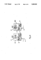
- FIG. 2 shows a typical installation of the automatic shutoff valve system for a hot water heater.
- FIG. 3 shows an AC power line interconnection as another embodiment of the automatic shutoff valve system.
- FIG. 4 shows in more detail the transmitter and receiver modules of FIG. 3.
- FIG. 5A is a cross-sectional view of the water shutoff valve;
- FIG. 5A' is an insert view of FIG. 5A.
- FIG. 5B is a top view of the water shutoff valve with cutaway views.
- FIG. 5C is a side view of the water shutoff valve to illustrate the latch mechanism.
- FIG. 6 is a schematic diagram of the electronic circuitry in accordance with this invention.
- FIGS. 7A through 7D illustrate the logic flowchart for the microcontroller software in accordance with this invention.
- FIG. 1 is a view of a hard-wired embodiment of the automatic shutoff valve system.
- the water shutoff valve 1 includes conventional pipe fittings 2 and 3 and a valve re-latch knob 5.
- Multi-conductor cable 6 provides the necessary electrical connections between the valve 1 and the control module 7.
- Slide switch 8 provides a power on-off function.
- LED 9 is a visual indicator of both normal operation and alarm conditions.
- Aperture 10 allows transmission of sound from an internal piezoelectric alarm transducer described below.
- Slide switch 11 provides selection between one or two valve operation, as might be the case in hot and cold water applications.
- Pushbutton switch 12 provides the double function as both a valve trip-test activation means and an alarm delay means.
- AC power adapter 13 is a line-isolation low voltage D.C.
- Cable 14 and plug 15 are the connections between the adapter 13 and the control module 7.
- Wire cable 16 is the signal line connections between the control module 7, via cable 6 and water shutoff valve 1, and the leak detection module 17.
- the cutaway drawing of the module 17 displays the two probes 18 and 19 which, when placed in contact with a conducting liquid, function to produce a liquid leakage signal to the appropriate circuits in the control module 7.
- Connector 20 connects to an additional water shutoff valve as explained below.
- FIG. 2 shows a typical hot water heater installation incorporating a water shutoff valve system.
- Water shutoff valve 1 is installed in the cold water input pipe 21 of water heater 23.
- Water pipe 22 is the hot water outlet for distribution to the faucets, etc.
- Control module 7 is shown mounted on the wall adjacent to the valve 1 and connected to the valve via cable 6.
- Leak detection module 17 is located under the water heater 23, with cable 16 providing the necessary interconnection means.
- FIG. 3 shows an alternate embodiment of the water shutoff valve system in which an AC line-carrier provides leak detection signals to the master control module 24.
- Line-carrier systems are well known and commonly used in such applications as home intercoms and remote lamp/appliance controls.
- This embodiment permits additional leak detection modules to be placed in remote locations which are not easily connected to the control module 7 via wires.
- a water shutoff valve can be installed in a main water supply line and controlled by numerous remote leak detection modules.
- Water shutoff valve 1 is shown connected to leak detection module 17 via cable 16 as previously described. Cable 6 again provides connection between valve 1 and the master control module 24.
- Master control module 24 is a modified version of control module 7 and receives leak detection signals from the slave modules 25a and 25b using the line-carrier method.
- the master control module 24 and slave modules 25a and 25b are shown plugged into standard wall outlet boxes 26a, 26b, and 26c respectively. Wires 29 and 30 provide the normal source of alternating current as would be found in a standard wiring installation.
- Each of the slave modules has its own leak detection module 17 connected via cable 16. If slave module 25a and/or 25b were to detect a water leakage an encoded signal would be transmitted via the AC power lines 27 and 28 to the master control module 24. Upon receiving such a signal, master control module 24 would initiate a normal valve shutoff and alarm procedure.
- this embodiment description utilizes a line-carrier system it should be recognized that a radio-frequency system may be substituted.
- FIG. 4 is a more detailed block diagram of the internal circuits of the master control module 24 and slave modules 25a and 25b.
- Master control module 24 contains a receiver/decoder circuit 31 which may receive either radio frequency signals or AC line-carrier signals and route the amplified and decoded signals to the master control circuit 32.
- the output from master control circuit 32 is routed via cable 6 as previously described and functions in a manner similar to the control module 7.
- the battery backup circuit 33 functions to supply power to the receiver and master control circuits if primary AC power fails.
- Slave modules 25a and 25b contain a sensor control circuit 35 which receives its input from the leak detection module via line 16 as previously described. Any water leakage signal is sent to the transmitter/encoder 34 which encodes the signal to be compatible with the code setting of the master control module 24. Such encoding is necessary to reduce the possibility of initiating a water valve shutoff based on extraneous signals or signals from other water shutoff systems.
- the encoded signals are now sent via the AC power lines or radio frequency as previously described.
- the battery backup circuit 36 functions to supply power to circuits 34 and 35 in the event of a failure of primary AC power.
- FIG. 5A is a cross-sectional view of the water shutoff valve 1.
- Valve 1 is a spring-loaded ball valve which permits changing its flow status from ON to OFF or vice versa by rotating the ball through 90 degrees.
- the valve is shown in a closed condition with valve ball 36 pressing against the 0-ring seal 39, thus preventing fluid flow through the pipe fitting and input port 3 to the pipe fitting and output port 2.
- Through-hole 37 in valve ball 36 provides the path for fluid flow when the valve ball 36 is rotated 90 degrees.
- a novel ball rotation system which allows the valve ball 36 to rotate with a small clearance or very slight contact between itself and the 0-rings 38 and 39 when in the valve open condition, to prevent contamination particles from entering the valve mechanism.
- Rollers 40 and 42 which rotate on pins 41 and 43 respectively reduce friction.
- Roller 40 normally rides on the upper collar surface 56 of valve ball 36 during the open valve portion of rotation.
- roller 42 rides on the lower collar surface 54. In this valve open condition the valve ball lightly touches the 0-rings 38 and 39 as previously stated.
- FIG. 5A' The valve-closed condition is more easily understood by the insert view 57 (FIG. 5A') of FIG. 5A.
- the top portion of the valve ball is shown rotated to produce a top view of the valve ball 36. While this inserted view shows the top of valve ball 36 and roller 40, it should be understood that a bottom view would similarly show the valve ball collar 54 and associated roller 42.
- roller 40 is resting in detent 53 of the valve ball collar 56 and, while not shown, bottom roller 42 rests in detent 58. This allows the surface of valve ball 36 to press against O-ring 39 due to the resulting inlet water pressure.
- spring pressure could be provided to ensure ball valve 36 closure against O-ring 39 in the event of low water pressure. This could be accomplished using spring-loaded rollers, or the equivalent, pressing against the water inlet side of valve ball collars 56 and 54. Also note that to allow valve ball 36 to move in a +X direction, the bottom, rectangular end of shaft 44 fits into rectangular slot 51.
- knob 5 To reset the valve to an open condition, knob 5 must be rotated in a clockwise direction as viewed from the top of valve 1.
- Shaft 44 couples the rotational torque from knob 5 to valve ball 36.
- O-ring 45 seals against fluid leakage.
- a clockwise rotation of valve ball 36 causes the outer diameter of upper collar 56 to engage roller 40 in a manner which produces a movement of valve ball 36 in a -X direction.
- the outer diameter of lower collar 54 likewise engages roller 42.
- Bottom cover 49 provides access to the inner cavity of valve body 48 to facilitate assembly. O-ring 59 seals against fluid leakage. Top cover 50 encloses the rotor 47.
- FIG. 5B is a top view of water shutoff valve 1 showing cutaway views of the rotor 47 and torsion spring 46 locations.
- Rotor 47 is now shown in a position representing a valve-open condition.
- the inner coil of torsion spring 46 is shown attached to the hub portion of valve body 48.
- the outer spring coil is attached to the rotor 47 using a hook arrangement at point 55.
- Spring 46 is now exerting a counterclockwise torque on rotor 47.
- the rotor is now locked in a valve-open position by the valve latching mechanism to be described later.
- the valve latching mechanism releases the rotor 47 to rotate in a counterclockwise direction in order to establish a valve-closed condition, the amount of rotation is restricted to 90 degrees when rotor surface 61 hits the stop pin 60. Because rotor 47 is physically attached to shaft 44 the valve ball 36 will likewise be placed in a valve-closed condition as previously described in conjunction with FIG. 5A.
- FIG. 5C shows a cutaway view of the latch mechanism used to hold the valve in an open condition until a valve closure is required.
- Latching arm 62 engages rotor 47 at surface 47a in order to prevent any rotor movement.
- Latching arm 62 is pinned at point 74 and would normally rotate in a clockwise direction about that point due to the rotational moment impressed on the latching arm by rotor 47.
- the end of latching arm 62 contacts the lip of trip arm 64 in a manner which does not permit any rotation of the latching arm.
- Trip arm 64 rotates about point 75 and it receives a counterclockwise retaining torque from wire spring 65 which also holds trip wire 66 in a taut condition.
- Trip wire 66 is a special shape memory alloy, metallic wire marketed under the name BioMetalTM by Mondotronics, Inc., Sunnyvale, Calif., which has the property of contracting in length when heated to a specific temperature.
- the method of heating involves passing an electrical current, on the order of 400 milliamperes, through the wire.
- Trip wire 66 is fastened at one end to mounting terminal 67 which, in turn, is fastened to printed circuit board 70.
- the other end of the trip wire is fastened to the bottom of trip arm 64 with a short extension to terminal 72 which provides a necessary electrical connection to printed circuit board 70.
- FIG. 6 is a schematic diagram of the circuitry used in conjunction with the automatic shutoff valve system.
- a key element of the electronic circuitry is the ⁇ C 80.
- the COP-426C manufactured by National Semiconductor Corporation was chosen. It is a 4-bit ⁇ C which is a low-power and cost effective means to attain the objectives.
- the optional AC power adapter 13 and its associated cable 14 and plug 15 are shown attached.
- the receptacle into which plug 15 is inserted is comprised of grounding collar 81, spring contact 84, and mating contact 85.
- the grounding collar 81 makes contact with the negative terminal 82 of plug 15, and the inverted-V portion of spring contact 84 makes contact with the tip 83 of plug 15 which is at a positive potential of about 4.5 volts DC.
- spring contact 84 and mating contact 85 are separated thereby removing the shorting path across resistor 87 and diode 88.
- Resistor 87 is used as a current limiting resistance in the charging path for rechargeable batteries 86a, b, and c.
- Diode 88 provides a low impedance current path around resistor 87 in the situation where the AC adapter is installed but a primary AC power failure has taken place. If rechargeable batteries such as the standard 1.25 volt AA size Ni-Cad type are used they will be trickle-charged by the AC adapter to provide backup power in the event of a primary AC power failure. If non-rechargeable batteries such as a 1.5 volt AA size alkaline type are used as components 86a, b, and c, the voltage across resistor 87 would be essentially zero and no undesirable charging current would result. As an alternate arrangement a switch could be used to disconnect resistor 87 if non-rechargeable batteries were used.
- Power switch 8 includes two sections 8a and 8b. When the contacts of section 8a are placed in the ON position, voltage is applied to diode 89, resistor 90, and terminal V+, from which it is distributed to the three load terminals also labeled V+. Diode 89 is a unidirectional current path to the Vcc terminal of ⁇ C 80, filter capacitor 92, and alarm driver transistor 99. Diode 89 allows capacitor 92 to filter supply voltage fluctuations to the ⁇ C 80 when large current loads are placed on the batteries during valve trip activation.
- capacitor 91 When voltage is first applied to resistor 90, capacitor 91 begins charging toward the supply voltage.
- the ⁇ C 80 internal circuits utilize this delayed voltage application at the ⁇ R ⁇ terminal to initialize itself to a reset state, before proceeding to execute the resident program.
- the contacts of switch section 8b are also closed in an ON position, voltage is applied to pull-up resistor 135 and the emitter of PNP transistor 134.
- Under software control ⁇ C 80 terminal L1 which is normally high, is driven low in order to allow emitter to base current to flow, thereby switching transistor 134 to a conductive state. Nearly the full battery voltage is now impressed across the low voltage detector 133 to ground.
- the battery voltage applied to resistor 137 for leak detection purposes is explained below.
- Voltage detector 133 is an integrated circuit containing a voltage reference and comparator to determine when the voltage, applied between its input terminal and ground, drops below a prescribed value.
- An example of such an integrated circuit is a model S-8053ANO, manufactured by Seiko Instruments Inc. Normally the output terminal of voltage detector 133 is high, but will switch to a low state when the battery voltage drops below approximately 3.6 volts. During the time at which the battery voltage testing is performed (terminal L1 is low), ⁇ C terminal L2 status is determined. If a low battery condition exists, the output of voltage detector 133 will hold terminal L2 low which will result in the software program initiating a low battery warning to be described later in detail.
- ⁇ C 80 Connected to ⁇ C 80 terminals CK1 and CKO is a clock oscillator circuit comprised of a 32.768 Khz crystal 93, resistors 96, 97, and capacitors 94, 95. These components, in conjunction with the ⁇ C internal circuitry, produce a master clock signal which ⁇ C 80 uses to perform various timing and control functions.
- Switch 12 performs a dual function. Terminal G2 of ⁇ C 80 is periodically sampled under program control to determine the open or closed status of switch 12. If the shutoff valve system is in a non-alarm mode (there has been no leak detection), holding switch 12 closed for a period of 3 seconds will cause the ⁇ C program to initiate a valve closure, typically for test purposes. If, however, the shutoff valve system is in an alarm mode, the momentary closure of switch 12 causes the ⁇ C program to inhibit the visible and audible alarm signals and delay their reactivation for one hour. Each momentary closure of switch 12 adds one more hour delay, up to a maximum of 10 hours.
- a short audible beep and visual blink are produced after each switch reopening to provide a sensory feedback confirmation that an hour delay has indeed been added.
- the next momentary closure of switch 12 causes a return to a zero delay condition.
- a longer duration audible beep and visual blink are produced.
- the above sensory signals are produced by piezoelectric transducer 103 and LED 9 whose drive circuits include transistors 99 and 104, resistors 100, 101, and 105, and inductor 102. During normal, non-alarm conditions LED 9 will blink once each minute to provide an indication that the system is operating.
- transistor 99 is turned on as previously described.
- NPN transistor 104 is switched on and off at a 2 kilohertz rate by a square wave of the same frequency made available, through program control, at the SK output terminal of ⁇ C 80.
- Resistor 105 limits the base-emitter biasing current during the peak positive portion of the SK square wave.
- the resulting 2 kiloHertz alternating potential across piezoelectric transducer 103 causes it to emit a 2 kiloHertz tone.
- Inductor 102 resonates with the piezoelectric transducer 103, causing a larger voltage swing to occur across the transducer 103, and thus a greater audio output than would be possible with just the transducer alone.
- the audible and visible alarm signals are produced in a coded format to allow differentiation between leak detection, a detectable malfunction, or a low battery condition. For example, if a water leak is detected the shutoff valve(s) is closed and a series of three blinks from LED 9 and beeps from transducer 103 is produced every 15 seconds. If a malfunction is detected, a series of two blinks and beeps are produced every 15 seconds. Likewise, if a low battery condition exists, a single blink and beep are produced every 15 seconds.
- a jammed valve condition requires that an urgent attention alarm be provided.
- the software program causes a series of successive blinks and beeps to be produced for a period of time, say one minute, followed by a reversion to the standard alarm format to conserve battery power.
- the next subject to be addressed is leak detection. Again referring to FIG. 6, and more specifically to the collector of PNP transistor 134, it was described above that driving terminal L1 of ⁇ C 80 low causes transistor 134 to conduct, thus impressing the battery voltage at the input terminal of the low voltage detector 133 and to resistor 137. Thus, the low voltage detection circuit is enabled only when necessary, conserving battery power. Applying voltage to resistor 137 to enable the leak detection circuitry only when necessary serves another purpose. It is known that applying a continuous DC potential across two metal probes (for the purpose of detecting a current flow between the two probes due to the presence of a conductive fluid) can cause a contamination of the probe surfaces and, hence, a reduction in the detection sensitivity and reliability. Certain prior art products incorporate a circuit for producing an alternating voltage between the probes to prevent such unwanted polarization and contamination. Such circuits are relatively complex in their implementation.
- the method used in accordance with the current invention in contrast involves applying a DC potential across the detector probes only during the few milliseconds it takes to perform the necessary measurement, thereby making the effects of probe polarization relatively insignificant.
- PNP transistor 134 is now conducting and a positive battery voltage is applied to resistor 137.
- the other end of resistor 137 exits control module 7 on wire 143 via cable 6, jumpers through printed circuit board 70 and is routed via cable 16 to the leak detector module 17.
- jumper 141 connects wire 143 to leak detector probe 19.
- Leak detector probe 18 connects to jumper 142, which in turn exits the leak detector module 17 on wire 146 and is routed through cable 16 to printed circuit board 70 where it jumpers back through cable 6 to control module 7.
- Wire 146 now connects to the junction of terminating resistor 109 and current limiting resistor 110.
- the above described circuit constitutes the path through which current flows if a conductive fluid is placed in contact with leak detection probes 18 and 19. If such a condition exists, the resulting current forward biases NPN transistor 111, causing it to conduct current between its collector to emitter.
- Terminal G3 of ⁇ C 80 under program control, periodically outputs a small current and test to determine if transistor 111 is conducting or not. If transistor 111 is conducting, it represents a leak condition and the appropriate software program action is initiated.
- a self-test feature electronically places a large resistance across the leak detection probes 18 and 19 to simulate a fluid leak condition.
- terminal D2 of ⁇ C 80 which is normally high, will be driven low and, via limiting resistor 106, will cause PNP transistor 107 to conduct.
- the emitter of transistor 107 is connected to leak detector probe 19 via wire 144.
- the collector of transistor 107 is connected to resistor 108 which has a value of about 330K ohms to simulate the conductivity of a fluid such as water.
- the bottom of resistor 108 is connected to leak detector probe 18 via wire 145.
- resistor 108 is essentially placed across leak detector probes 18 and 19. In this test condition a current flows through the leak detection circuit and cause transistor 111 to conduct, providing there is no circuit malfunction. Any circuit failure, such as a broken wire to the leak detection module 17, causes transistor 111 to be in a non-conductive state when terminal G3 of ⁇ C 80 tests for the transistor's status. If the software program, which is expecting to find transistor 111 conducting, instead finds it not conducting it will initiate a malfunction alarm routine. It can be seen, therefore, that by adding two wires, 143 and 146, to the leak detection circuit a more failsafe testing scheme is implemented.
- leak detection module 147 can be added to provide coverage of an additional area. To add module 147 it is necessary simply to remove jumpers 141 and 142 and install them on module 147 in positions 141a and 142a. Additionally, the modules must be interconnected by attaching the wires in the following sequence; wires 148 to 143, wires 149 to 144, wires 150 to 145, and wires 151 to 146.
- the software program initiates a valve closure routine which involves turning on the driver circuits to activate the valve trip mechanism, or mechanisms in the case of a two valve system.
- a valve closure routine which involves turning on the driver circuits to activate the valve trip mechanism, or mechanisms in the case of a two valve system.
- the software program services one or two depending on the setting of switch 11. If switch 11 is in the ⁇ 2 ⁇ position the software program detects this low condition when it periodically tests the status of terminal L0 on ⁇ C 80.
- valve 1 refers to those circuits on printed circuit board 70 and "valve 2" refers to those circuits on printed circuit board 140.
- the normal state of terminal L6 of ⁇ C 80 is either high or tri-state (open). In this condition PNP transistor 119 is not conducting, with its emitter connected to V+ and its base also at V+, via pull- up resistor 120. To turn on current to the valve trip mechanism, terminal L6 is driven low, thus causing forward biasing current to flow from the emitter to base of transistor 119 and current limiting resistor 121.
- Transistor 119 now conducts current via resistor 115 to the junction of terminating resistor 114, the collector of NPN transistor 116, and the base of NPN transistor 118. Because of this transistor 118 base drive, current flows from the V+ terminal through conductor 153 to the contact 69 and its associated contact of leaf-switch 68, then through BioMetalTM wire 66 to the collector-emitter of transistor 118, and finally through resistor 117 to ground. As previously described, the current through BioMetalTM wire 66 causes it to contract in length thus tripping the valve latch mechanism. To prevent excessive current flow through the BioMetalTM wire when the supply voltage V+ is high, the voltage developed across resistor 117 forward biases NPN transistor.
- transistor 116 when the voltage across resistor 117 reaches approximately 0.6 volts (which represents about 400 milliamperes through the BioMetalTM wire) transistor 116 will begin to conduct in a manner to shunt away base drive current to transistor 118, which in turn causes a higher voltage drop between the collector to emitter of transistor 118, and a current limiting action will take place.
- the collector of transistor 118 is also connected to resistor 113 which in turn is connected to terminating resistor 112 and terminal L7 of ⁇ C 80.
- the software program initiates a valve closure routine it also begins testing the status of the voltage at terminal L7. As long as terminal L7 is high, it indicates that the shutoff valve is still open.
- switch 68 opens and the voltage at resistor 113 and hence the voltage at L7 drops to zero.
- the software program removes drive current to transistor 119 by returning terminal L6 to a high state. If drive current is applied to the valve trip mechanism for more than 4 seconds without detecting a successful valve closure, the software program assumes a jammed valve condition and removes the drive current and initiates an urgent attention alarm.
- Terminals L4 and L5 of ⁇ C 80 perform functions identical to terminals L6 and L7 respectively.
- Transistor 128 provides the drive for the valve 2 trip mechanism via conductor 154 in conjunction with the V+ voltage connected to a second valve printed circuit board 140 via conductor 155.
- Conductors 154 and 155 comprise cable 4 and are connected to printed circuit board 140 using connector 20.
- BioMetalTM wire 152 and switch components 138 and 139 perform identical functions as items 66, 69 and 68 respectively on printed circuit board 70.
- terminal L3 of ⁇ C 80 may be optionally grounded using jumper 132. This jumper is only used to expedite factory testing and, when installed, the software program switches several internal timers to a "quick" mode which reduces the time required to perform certain functions.
- the ⁇ C 80 operates in accordance with a program conventionally resident in read only memory associated with ⁇ C 80. This program is shown in the Microfiche Appendix which is a part of this disclosure. Permission is given to make facsimile reproduction of this Microfiche Appendix from Patent Office files, but all other copyright rights are reserved.
- the START block represents the point at which power is initially applied to micro-controller 80 (FIG. 6). To avoid repetitive references throughout this portion of the flowchart description, all references to a particular component or components are made to those in FIG. 6.
- the random access memory (RAM) is next cleared, followed by an initialization of pertinent pointers and counters.
- the first operation to be performed is the testing for a low battery condition. It will be noted that a reentry point labeled LOOP 1 is provided just prior to the low battery test. Depending on the results of the low battery test the LOW BATT flag may be set or reset.
- the liquid probe circuit is tested by turning on transistor 107, thus simulating a water-leak condition by placing resistor 108 across probes 18 and 19.
- the results of this test determine whether MALFUNCTION #1 flag is set or reset. At this point a determination must be made regarding whether shutoff valve number 1 (or additionally shutoff valve 2 if two valve operation is involved) has been tripped to a valve closed condition. If the VALVE TRIPPED flag has been set the program will not perform the trip wire test since those circuits are presumably open as a result of the valve-open condition. If the VALVE TRIPPED flag is not set, a test of the valve trip circuits is made.
- valve 1 If it is set and valve 2 is open, the program jumps to the SWCHK entry point (FIG. 7C). If the valve is now closed the URG 2 flag is reset. Returning to the VLV 1 CLSD? test block, if it was determined that valve 1 is now closed, the URG 1 flag is reset and another two valve system test is made in this branch of the program (2 VLV SYS? block). If it is not a two valve system the program proceeds to the VLV 1 RST? block where a test is made to determine if valve 1 has been reset to an open-valve condition. If it has, the next test is whether the URG 1 flag is set and if the flag is not set the program resets all pertinent flags and timers to restore a normal valve-closed condition. In the last three test blocks just described, there are three commonly connected outputs which result in a program jump to the SWCHK entry point (FIG. 7C).
- FIG. 7B pertains primarily to the action taken by the program to trip the valve latch mechanism(s) as a result of a fluid leak detection or a test valve closure request resulting from switch 12 being held closed for more than three seconds.
- the VLV1 TRIP'D flag is tested to determine if the valve 1 closure routine has been completed. If the VLVI TRIP'D flag is set, the program next determines if this is a one or two valve system. If it is a one valve system, the program proceeds to the entry point SWCHK (FIG. 7C).
- a test is made to determine if the valve 2 closure routine has been completed and, if it has, also proceeds to the entry point SWCHK (FIG. 7C).
- a test is next made to determine whether the leak timer has counted down to zero.
- the purpose of the leak timer is to require that a leak condition exist for at least 1 second before initiating a valve closure routine, thus reducing the possibility of erroneous valve closure. If the timer has not counted down to zero, the timer value is decremented and the LEAK TIMER flag set, then the program jumps to the TSYNC entry point (FIG.
- terminal L7 of ⁇ C 80 is tested to see if the voltage at that point has dropped to zero, indicating that valve 1 closure has been completed and, if it has not, the #1 TRIP flag is set.
- the program now jumps to TSYNC (FIG. 7C) which causes the program to continuously loop back to the TRIPTIM1 entry point until either a valve trip confirmation is obtained or the valve trip timer has decremented to zero, which would occur after 4 seconds duration. If the valve trip timer does reach zero it would indicate a possible jammed valve condition, in which case the URG1 flag is set, to initiate an urgent alarm mode.
- valve 1 trip current is turned off, the #1 TRIP flag is reset, the VLV1 TRP'D flag is set, and the valve trip timer is set to four seconds.
- the program now tests to determine if this is a one or two valve system as described earlier. It can be seen that the remainder of the FIG. 7B flowchart is essentially a duplication of the just described valve 1 trip function, with the exception that it pertains to valve 2.
- FIG. 7C begins with the SWCHK entry point where the first decision is whether switch 12 is closed. If it is closed, the switch timer is next checked to see if it is zero, indicating that switch 12 has been held closed for a total of three seconds. If it has not, the three second timer is decremented and the SW-CLOSED flag is set, then the program jumps to TSYNC. Assuming for example that it is desired to initiate a valve trip condition by holding switch 12 closed for three seconds, the switch timer is decremented to zero. At this point the SW-CLOSED flag is reset and a test is made to determine if valve 1 has tripped. If it has not tripped, the program jumps to the TRIPTIM1 entry point (FIG.
- MIN CTR The minute counter
- TSYNC represents a central program entry point in that a ⁇ C 80 internal counter is used to establish a one quarter second program cycle time.
- the internal counter which is continuously incrementing, is now tested to determine if it has reached its maximum, overflow count. If it has not overflowed the program continues to loop back to the TSYNC point until an overflow condition is reached.
- the internal counter is preset to a value which produces another overflow one-quarter second later. Then the program exits that loop and advances the MINUTE counter.
- the program Before proceeding to the LEAK TIMER flag test, it is necessary to return to the ANY ALARM FLG SET? block. If the ALARM FLG was set, and the SW CLSD flag is not set, the program once again proceeds to the TSYNC entry point. If, however, the SW CLSD flag is set, it indicates that switch 12 was momentarily closed and, since an alarm flag is set, a request is being made to inhibit the visible and audible alarms and add an hour delay before they are reinstated. In this program path the SW-CLOSED and PASS 1 flags are reset and the one hour inhibit counter (1 HR INH CTR) is incremented.
- FIG. 7D shows the program routines used to turn on and off the LED 9 and piezoelectric transducer 103 according to the particular alarm requirements.
- the first decision that is made at the PASS1 entry point is whether or not the PASS1 flag is set. Assuming the flag is not set, there are several initiating tasks that are performed during the first pass through this program alarm section. As indicated on the flowchart these tasks range from setting the PASS1 flag to setting the URGENT COUNTER to one minute. Once the PASS1 flag is set, any future passes will bypass this initialization loop until all the alarm flags are no longer set as indicated at the last step of FIG. 7C.
- the inhibit flag is checked and, if set, the program enters its alarm inhibit loop. As previously described, restoration of the visible and audible alarm transducers can be delayed in one hour increments.
- the system minute counter is tested to see if it has decremented to zero and, if not, the program returns to the LOOP1 entry point on FIG. 7A. If the system minute counter is zero the INH. MIN/HR will be decremented. After sixty decrements of the minute portion of the INH. MIN/HR counter, the HOUR counter will decrement. If, for example, the INHIBIT HOUR counter had been set to one hour, the first decrement of this counter after an elapsed one hour period would result in the INHIBIT flag being reset.
- the program would now proceed to the URGENT FLG SET? block. Assuming that the URGENT flag is not set, the 15 SECOND ALARM TIMER is tested. As previously described, the coded alarm sequence is repeated every 15 seconds until the particular problem which causes the alarm is solved, or the alarm is inhibited. If the 15 SECOND ALARM COUNTER has not reached a zero count, it is decremented. Next, the BEEP & BLINK counter is tested and if, for example, the counter is now at three (representing a leak detection alarm) the BEEP & BLINK DRIVE-OFF flag is tested.
- the program sets the flag, then turns on the drive to the LED 9 and the piezoelectric transducer 103. Next it decrements the BEEP & BLINK counter and finally exits to the LOOP1 entry point on FIG. 7A. With the BEEP & BLINK DRIVE-OFF flag now set it can be seen that the OFF counter is tested for a zero count. At this point the counter is not zero so it is decremented and the beep and blink drive are turned off.
- the beep and blink transducers are turned on for one program loop period then off for three periods. This sequence repeats until the BEEP & BLINK counter equals zero, at which time the beep and blink drive is turned off.
- the AIP flag is reset and the ALARM TIMER is set to 15 seconds, thus allowing the BEEP & BLINK counter to be set to its appropriate alarm number (FIG. 7C).
- the URGENT flag is set, the BEEP & BLINK counter are repetitively set to one for a one minute period, then the alarm sequence reverts to the standard 15 second period.
- control module and AC adapter have been described as two separate units, it should be recognized that, with the appropriate modification, the AC adapter could be made an integral part of the control module.
- the LED and piezoelectric transducers can, with the appropriate modification, be removed from the control module or duplicated in a manner to provide a remote alarm indicator.
- the described automatic shutoff valve has pertained to applications involving water leaks.
- the leak detection module 17 could be replaced by a switching device actuated by a natural gas and/or seismographic detector. In this way the shutoff valve, when installed in a natural gas or propane supply line, would be tripped to turn off the flow of gas in the event of a detected gas leak or earthquake of a predetermined magnitude.
- the use of the 4-wire cable 16 would still be applicable in this case since it would provide the same means of monitoring the wiring integrity between any of the above detector systems and the control module 7.
Abstract
An automatic shutoff valve system for installation for instance in the water supply line to a hot water heater includes a sensor to detect leakage electrically by sensing moisture, and then shutting off the supply line in response. The valve mechanism includes a spring loaded ball valve normally latched in the open position which is unlatched and hence closes by the contraction of a BioMetal™ wire which activates a torsion spring to rotate the ball valve. The valve is controlled by a microprocessor which includes self test features, and the valve system may operate for a year or more on battery power.
Description
This disclosure includes a Microfiche Appendix having a total of 24 frames on 1 fiche and showing a computer program.
1. Field of the Invention
This invention relates to an electronically controlled valve which senses a leakage of water or other conductive fluid, and shuts off the source of leakage before extensive structural or property damage can occur. By utilizing a microcontroller-based system in conjunction with a novel valve mechanism, this automatic shutoff valve provides a cost-effective system suitable for various household and commercial applications.
2. Description of the Prior Art
There are situations in which no one is present to hear an alarm when a water leak occurs. Broken water lines on water heaters have been responsible for extensive property damage, especially as a result of earthquakes. In the case of automatic dishwashers and clothes washers the breakage of input water hoses or faulty water level sensing switches has also been known to cause extensive property damage.
There are existing devices, such as the "Water Alert™" manufactured by Dorlen Products, which provide an audible alarm when the presence of water is detected thus alerting an individual that immediate attention is required. This provides no protection if no one is present at the time the alarm sounds.
Another commercially available system is the "Fluid Guard," manufactured by Fluid Guard Incorporated. This system detects a water leak condition by monitoring the volume of water flow versus time. It has several disadvantages such as a somewhat complex plumbing installation, need for sensitivity and time adjustments, and high cost.
Yet another device is described in U.S. Pat. No. 4,324,268, dated Apr. 13, 1982, and issued to Avram A. Jacobson. Jacobson utilizes a transistor to sense the presence of liquid via a resulting base-to-emitter current. This current causes transistor collector current to flow which is directly drives a latching relay. The relay, when latched on, energizes a solenoid which, in turn, closes the water valve thus shutting off water flow. The system is powered by a rectified AC power source which is isolated from the AC mains by a transformer. While the function of this valve system is apparent, there are several disadvantages. First, if there is a power failure either during or after the valve closure due to a water leak condition, the valve will once again open allowing the water leak to continue. Although Jacobson states that a battery power source can be provided, it is also mentioned that the solenoid coil will produce sufficient heat during extended periods of energization to warrant its location away from the electronic components. With this in mind, it would require a battery of sizable capacity to maintain the valve in a closed condition for long periods of time. Next, while a remote test switch is provided to simulate the presence of a water leak, and thus induce a valve closure, the switch must periodically be manually activated to test the system. This requirement in all likelihood would very seldom, if ever, be performed, thus compromising system reliability. Lastly, the test switch simulates a water leak condition by effectively placing a resistance across the sensing transistor input lines which are physically located within the control circuit enclosure. Such a circuit configuration fails to test for breakage of either or both of the moisture probe connecting wires which would render the system ineffective. Activating the test switch would indicate the system is operating properly in spite of such a failure.
This invention provides a leak detection and shutoff valve system which overcomes the disadvantages of prior art devices. This valve system has the advantage of both turning off water flow and providing an audible and visual alarm rather than just sounding a warning, as is the case with many commercially available devices. In one embodiment a spring-loaded ball valve is normally latched in an open condition thus allowing unimpeded water flow. The valve latch mechanism holds the valve in the open condition until it is unlatched through the action of a BioMetal™ wire which contracts in length when heated by the passage of electrical current through the wire. Unlatching the latch mechanism allows a torsion spring to apply sufficient torque to the ball portion of the valve to rotate it 90 degrees to a closed position thus shutting off water flow. The ball valve allows rotation with minimal friction until the closed position is reached, at which time the ball firmly seats against a sealing 0-ring.
The valve assembly is connected to a control module via a multi-wire cable. The control module contains a low-power 4-bit microcontroller which has a resident program to provide the necessary logic and control functions. Moisture detection is accomplished by a well known method of allowing the presence of a conducting liquid to increase the current and/or voltage to a transistor or logic gate. The transistor method is used in one embodiment to provide a protective buffer between the sensing probe circuit and the μC input. The leak detection module includes two metallic probes which are connected to the control module via a four-wire cable. Each leak detection module also contains a jumper arrangement to allow connecting additional detection modules in a series/parallel circuit.
The control module housing can be mounted on a wall location adjacent to the valve. The control module also includes a light-emitting diode (LED) and piezoelectric transducer to provide visible and audible alarm functions respectively. A power switch applies D.C. power to the various circuits. A valve selector switch allows the control module to control one or two water valves. Two valve operation might be found in situations such as a clothes washer where both hot and cold water are independently supplied to the appliance. A push button switch activates the valve shutoff by pressing the switch button for a prescribed time interval, for example 3 seconds. In addition, this switch delays the alarm condition until a more convenient time. For example, if a leak condition occurred at 2 A.M. and the valve has successfully shut off the leak condition, the resulting audible alarm could prove to be an annoyance. To solve this problem a feature is included by which each momentary closure of the pushbutton switch adds a one hour delay until alarm restoration, up to a limit of 10 hours. Thus, pressing the pushbutton switch seven times would cause the alarm to be reactivated after a seven hour delay.
In addition, an optional AC adapter power source can be connected to the control module thereby permitting it to operate without battery drain. This also permits the use of rechargeable batteries or primary batteries as a backup power source.
The second embodiment provides the same valve shutoff function but substitutes an alternate means of connecting additional leak detection modules to the control module. There may be situations in which adding leak detection modules via additional wire cabling, as in the first embodiment, would be inconvenient. The second embodiment modifies the control module such that it will not only monitor one or more wired leak detection modules and trip the water shutoff valve(s) as previously described, but also includes a receiver circuit either connected to the AC main supply lines or which is a radio frequency receiver unit. In either case this allows the control module to receive encoded signals from special leak detection transmitter modules and to trip the shutoff valve if the appropriate signal is received.
One advantage in accordance with this invention is achieved by use of a low-power microcontroller (hereafter referred to as a μC) to provide moisture detection, valve closure drive signals, alarm drive signals, and various other logic functions as described later. By using low power consuming circuitry the valve system is capable of operating on battery power for periods in excess of a year, thus not only providing battery backup in the event of AC mains power failure, but also allowing operation of the valve system in locations where mains power is either not available or difficult to provide. The μC also continuously tests for system malfunctions and alerts an individual of such conditions.
FIG. 1 shows a hard-wired embodiment of the automatic shutoff valve system.
FIG. 2 shows a typical installation of the automatic shutoff valve system for a hot water heater.
FIG. 3 shows an AC power line interconnection as another embodiment of the automatic shutoff valve system.
FIG. 4 shows in more detail the transmitter and receiver modules of FIG. 3.
FIG. 5A is a cross-sectional view of the water shutoff valve; FIG. 5A' is an insert view of FIG. 5A.
FIG. 5B is a top view of the water shutoff valve with cutaway views.
FIG. 5C is a side view of the water shutoff valve to illustrate the latch mechanism.
FIG. 6 is a schematic diagram of the electronic circuitry in accordance with this invention.
FIGS. 7A through 7D illustrate the logic flowchart for the microcontroller software in accordance with this invention.
The following description is of two embodiments of the mechanical and electronic aspects of this invention but does not preclude other embodiments which would be apparent to one skilled in the art.
FIG. 1 is a view of a hard-wired embodiment of the automatic shutoff valve system. The water shutoff valve 1 includes conventional pipe fittings 2 and 3 and a valve re-latch knob 5. Multi-conductor cable 6 provides the necessary electrical connections between the valve 1 and the control module 7. Slide switch 8 provides a power on-off function. LED 9 is a visual indicator of both normal operation and alarm conditions. Aperture 10 allows transmission of sound from an internal piezoelectric alarm transducer described below. Slide switch 11 provides selection between one or two valve operation, as might be the case in hot and cold water applications. Pushbutton switch 12 provides the double function as both a valve trip-test activation means and an alarm delay means. AC power adapter 13 is a line-isolation low voltage D.C. power and battery charging source for the control module 7. Cable 14 and plug 15 are the connections between the adapter 13 and the control module 7. Wire cable 16 is the signal line connections between the control module 7, via cable 6 and water shutoff valve 1, and the leak detection module 17. The cutaway drawing of the module 17 displays the two probes 18 and 19 which, when placed in contact with a conducting liquid, function to produce a liquid leakage signal to the appropriate circuits in the control module 7. Connector 20 connects to an additional water shutoff valve as explained below.
FIG. 2 shows a typical hot water heater installation incorporating a water shutoff valve system. Water shutoff valve 1 is installed in the cold water input pipe 21 of water heater 23. Water pipe 22 is the hot water outlet for distribution to the faucets, etc. Control module 7 is shown mounted on the wall adjacent to the valve 1 and connected to the valve via cable 6. Leak detection module 17 is located under the water heater 23, with cable 16 providing the necessary interconnection means.
FIG. 3 shows an alternate embodiment of the water shutoff valve system in which an AC line-carrier provides leak detection signals to the master control module 24. Line-carrier systems are well known and commonly used in such applications as home intercoms and remote lamp/appliance controls. This embodiment permits additional leak detection modules to be placed in remote locations which are not easily connected to the control module 7 via wires. Thus, a water shutoff valve can be installed in a main water supply line and controlled by numerous remote leak detection modules. Water shutoff valve 1 is shown connected to leak detection module 17 via cable 16 as previously described. Cable 6 again provides connection between valve 1 and the master control module 24. Master control module 24 is a modified version of control module 7 and receives leak detection signals from the slave modules 25a and 25b using the line-carrier method. The master control module 24 and slave modules 25a and 25b are shown plugged into standard wall outlet boxes 26a, 26b, and 26c respectively. Wires 29 and 30 provide the normal source of alternating current as would be found in a standard wiring installation. Each of the slave modules has its own leak detection module 17 connected via cable 16. If slave module 25a and/or 25b were to detect a water leakage an encoded signal would be transmitted via the AC power lines 27 and 28 to the master control module 24. Upon receiving such a signal, master control module 24 would initiate a normal valve shutoff and alarm procedure. Although this embodiment description utilizes a line-carrier system it should be recognized that a radio-frequency system may be substituted.
FIG. 4 is a more detailed block diagram of the internal circuits of the master control module 24 and slave modules 25a and 25b. Master control module 24 contains a receiver/decoder circuit 31 which may receive either radio frequency signals or AC line-carrier signals and route the amplified and decoded signals to the master control circuit 32. The output from master control circuit 32 is routed via cable 6 as previously described and functions in a manner similar to the control module 7. The battery backup circuit 33 functions to supply power to the receiver and master control circuits if primary AC power fails.
FIG. 5A is a cross-sectional view of the water shutoff valve 1. Valve 1 is a spring-loaded ball valve which permits changing its flow status from ON to OFF or vice versa by rotating the ball through 90 degrees. The valve is shown in a closed condition with valve ball 36 pressing against the 0-ring seal 39, thus preventing fluid flow through the pipe fitting and input port 3 to the pipe fitting and output port 2. Through-hole 37 in valve ball 36 provides the path for fluid flow when the valve ball 36 is rotated 90 degrees.
One major problem encountered in prior art ball valves or plug valves pertains to the high rotational forces required to change the fluid flow condition from ON to OFF or vice versa. The high rotational forces are primarily due to the friction between the valve ball and the 0-ring seals. This friction becomes more pronounced as the lubricants, normally applied during valve manufacturing, become sticky or hard as they age.
To minimize these friction forces, in accordance with the invention, a novel ball rotation system is used which allows the valve ball 36 to rotate with a small clearance or very slight contact between itself and the 0- rings 38 and 39 when in the valve open condition, to prevent contamination particles from entering the valve mechanism. Rollers 40 and 42 which rotate on pins 41 and 43 respectively reduce friction. Roller 40 normally rides on the upper collar surface 56 of valve ball 36 during the open valve portion of rotation. Likewise, roller 42 rides on the lower collar surface 54. In this valve open condition the valve ball lightly touches the 0- rings 38 and 39 as previously stated.
The valve-closed condition is more easily understood by the insert view 57 (FIG. 5A') of FIG. 5A. In this view the top portion of the valve ball is shown rotated to produce a top view of the valve ball 36. While this inserted view shows the top of valve ball 36 and roller 40, it should be understood that a bottom view would similarly show the valve ball collar 54 and associated roller 42. Again referring to the insert view 57, observe that, in the position shown, roller 40 is resting in detent 53 of the valve ball collar 56 and, while not shown, bottom roller 42 rests in detent 58. This allows the surface of valve ball 36 to press against O-ring 39 due to the resulting inlet water pressure. Although not shown, spring pressure could be provided to ensure ball valve 36 closure against O-ring 39 in the event of low water pressure. This could be accomplished using spring-loaded rollers, or the equivalent, pressing against the water inlet side of valve ball collars 56 and 54. Also note that to allow valve ball 36 to move in a +X direction, the bottom, rectangular end of shaft 44 fits into rectangular slot 51.
To reset the valve to an open condition, knob 5 must be rotated in a clockwise direction as viewed from the top of valve 1. Shaft 44 couples the rotational torque from knob 5 to valve ball 36. O-ring 45 seals against fluid leakage. Once again referring to insert view 57 it can be seen that a clockwise rotation of valve ball 36 causes the outer diameter of upper collar 56 to engage roller 40 in a manner which produces a movement of valve ball 36 in a -X direction. The outer diameter of lower collar 54 likewise engages roller 42. Once knob 5, shaft 44, rotor 47, and valve ball 36 are rotated 90 degrees to a latched, valve open position there is little if any frictional contact between the valve ball 36 surface and O-ring 39.
FIG. 5B is a top view of water shutoff valve 1 showing cutaway views of the rotor 47 and torsion spring 46 locations. Rotor 47 is now shown in a position representing a valve-open condition. The inner coil of torsion spring 46 is shown attached to the hub portion of valve body 48. The outer spring coil is attached to the rotor 47 using a hook arrangement at point 55. Spring 46 is now exerting a counterclockwise torque on rotor 47. The rotor is now locked in a valve-open position by the valve latching mechanism to be described later. When the valve latching mechanism releases the rotor 47 to rotate in a counterclockwise direction in order to establish a valve-closed condition, the amount of rotation is restricted to 90 degrees when rotor surface 61 hits the stop pin 60. Because rotor 47 is physically attached to shaft 44 the valve ball 36 will likewise be placed in a valve-closed condition as previously described in conjunction with FIG. 5A.
FIG. 5C shows a cutaway view of the latch mechanism used to hold the valve in an open condition until a valve closure is required. Latching arm 62 engages rotor 47 at surface 47a in order to prevent any rotor movement. Latching arm 62 is pinned at point 74 and would normally rotate in a clockwise direction about that point due to the rotational moment impressed on the latching arm by rotor 47. However, the end of latching arm 62 contacts the lip of trip arm 64 in a manner which does not permit any rotation of the latching arm. Trip arm 64 rotates about point 75 and it receives a counterclockwise retaining torque from wire spring 65 which also holds trip wire 66 in a taut condition.
To initiate a valve-closed condition the following chain of events takes place. First, the necessary drive signal from the previously mentioned control module 7 produces a heating current in trip wire 66, thus causing it to contract in length. The resulting force on the lower end of trip arm 64 causes the trip arm to rotate in a clockwise direction about point 75. The top end of trip arm 64 now moves a sufficient distance to release the end of latch arm 62. Latch arm 62 now rotates in a clockwise direction under the pressure of the rotor 47 which easily overcomes the retaining torque of wire spring 63. As rotor 47 rotates toward a valve-closed condition, the tip of latch arm 62 rides in contact with surface 47b. Once the rotor 47, and hence the valve ball 36 have rotated to a valve-closed condition, the tip of latch arm 62 rides in contact with surface 47c. At this position, point 62a of latch arm 62 contacts leaf-spring switch 68 causing its electrical contact to separate from the circuit board mounted contact 69. Had a mechanical malfunction occurred which might cause the valve to jam before it could reach a fully closed condition, the tip of latch arm 62 would not reach the surface 47c and switch 68, 69 contacts would not open. As will be seen later this information is used by the μC software to produce an urgent attention alarm to alert people that a malfunction has occurred. It should also be noted that connector 71 is mounted to printed circuit board 70 to provide the necessary signal routing and interconnection for cables 6, 16, and 4.
The following description is only of the hard-wired embodiment of the automatic shutoff valve system because this includes the elements necessary for operation. It is understood that an AC line-carrier or RF system may be adapted from this hard-wired system by one skilled in the art. FIG. 6 is a schematic diagram of the circuitry used in conjunction with the automatic shutoff valve system. A key element of the electronic circuitry is the μC 80. Although numerous commercially available microcontrollers could be used, the COP-426C, manufactured by National Semiconductor Corporation was chosen. It is a 4-bit μC which is a low-power and cost effective means to attain the objectives.
Beginning with the power supply circuitry, the optional AC power adapter 13 and its associated cable 14 and plug 15 are shown attached. The receptacle into which plug 15 is inserted is comprised of grounding collar 81, spring contact 84, and mating contact 85. The grounding collar 81 makes contact with the negative terminal 82 of plug 15, and the inverted-V portion of spring contact 84 makes contact with the tip 83 of plug 15 which is at a positive potential of about 4.5 volts DC. With plug 15 inserted, spring contact 84 and mating contact 85 are separated thereby removing the shorting path across resistor 87 and diode 88. Resistor 87 is used as a current limiting resistance in the charging path for rechargeable batteries 86a, b, and c. Diode 88 provides a low impedance current path around resistor 87 in the situation where the AC adapter is installed but a primary AC power failure has taken place. If rechargeable batteries such as the standard 1.25 volt AA size Ni-Cad type are used they will be trickle-charged by the AC adapter to provide backup power in the event of a primary AC power failure. If non-rechargeable batteries such as a 1.5 volt AA size alkaline type are used as components 86a, b, and c, the voltage across resistor 87 would be essentially zero and no undesirable charging current would result. As an alternate arrangement a switch could be used to disconnect resistor 87 if non-rechargeable batteries were used.
For the purpose of explanation assume that the AC adapter 13 is being used and the circuit is as shown with rechargeable batteries installed in 86a, b, and c. Power switch 8 includes two sections 8a and 8b. When the contacts of section 8a are placed in the ON position, voltage is applied to diode 89, resistor 90, and terminal V+, from which it is distributed to the three load terminals also labeled V+. Diode 89 is a unidirectional current path to the Vcc terminal of μC 80, filter capacitor 92, and alarm driver transistor 99. Diode 89 allows capacitor 92 to filter supply voltage fluctuations to the μC 80 when large current loads are placed on the batteries during valve trip activation.
When voltage is first applied to resistor 90, capacitor 91 begins charging toward the supply voltage. The μC 80 internal circuits utilize this delayed voltage application at the `R` terminal to initialize itself to a reset state, before proceeding to execute the resident program. When the contacts of switch section 8b are also closed in an ON position, voltage is applied to pull-up resistor 135 and the emitter of PNP transistor 134. Under software control μC 80 terminal L1, which is normally high, is driven low in order to allow emitter to base current to flow, thereby switching transistor 134 to a conductive state. Nearly the full battery voltage is now impressed across the low voltage detector 133 to ground. In addition the battery voltage applied to resistor 137 for leak detection purposes is explained below. Voltage detector 133 is an integrated circuit containing a voltage reference and comparator to determine when the voltage, applied between its input terminal and ground, drops below a prescribed value. An example of such an integrated circuit is a model S-8053ANO, manufactured by Seiko Instruments Inc. Normally the output terminal of voltage detector 133 is high, but will switch to a low state when the battery voltage drops below approximately 3.6 volts. During the time at which the battery voltage testing is performed (terminal L1 is low), μC terminal L2 status is determined. If a low battery condition exists, the output of voltage detector 133 will hold terminal L2 low which will result in the software program initiating a low battery warning to be described later in detail.
Connected to μC 80 terminals CK1 and CKO is a clock oscillator circuit comprised of a 32.768 Khz crystal 93, resistors 96, 97, and capacitors 94, 95. These components, in conjunction with the μC internal circuitry, produce a master clock signal which μC 80 uses to perform various timing and control functions.
The next subject to be addressed is leak detection. Again referring to FIG. 6, and more specifically to the collector of PNP transistor 134, it was described above that driving terminal L1 of μC 80 low causes transistor 134 to conduct, thus impressing the battery voltage at the input terminal of the low voltage detector 133 and to resistor 137. Thus, the low voltage detection circuit is enabled only when necessary, conserving battery power. Applying voltage to resistor 137 to enable the leak detection circuitry only when necessary serves another purpose. It is known that applying a continuous DC potential across two metal probes (for the purpose of detecting a current flow between the two probes due to the presence of a conductive fluid) can cause a contamination of the probe surfaces and, hence, a reduction in the detection sensitivity and reliability. Certain prior art products incorporate a circuit for producing an alternating voltage between the probes to prevent such unwanted polarization and contamination. Such circuits are relatively complex in their implementation.
The method used in accordance with the current invention in contrast involves applying a DC potential across the detector probes only during the few milliseconds it takes to perform the necessary measurement, thereby making the effects of probe polarization relatively insignificant. For the purpose of description, assume that PNP transistor 134 is now conducting and a positive battery voltage is applied to resistor 137. The other end of resistor 137 exits control module 7 on wire 143 via cable 6, jumpers through printed circuit board 70 and is routed via cable 16 to the leak detector module 17. Within leak detector module 17, jumper 141 connects wire 143 to leak detector probe 19. Leak detector probe 18 connects to jumper 142, which in turn exits the leak detector module 17 on wire 146 and is routed through cable 16 to printed circuit board 70 where it jumpers back through cable 6 to control module 7. Wire 146 now connects to the junction of terminating resistor 109 and current limiting resistor 110. The above described circuit constitutes the path through which current flows if a conductive fluid is placed in contact with leak detection probes 18 and 19. If such a condition exists, the resulting current forward biases NPN transistor 111, causing it to conduct current between its collector to emitter. Terminal G3 of μC 80, under program control, periodically outputs a small current and test to determine if transistor 111 is conducting or not. If transistor 111 is conducting, it represents a leak condition and the appropriate software program action is initiated.
There is an exception made to the conduction of transistor 111 representing a leak condition. A self-test feature electronically places a large resistance across the leak detection probes 18 and 19 to simulate a fluid leak condition. Periodically, under program control, terminal D2 of μC 80, which is normally high, will be driven low and, via limiting resistor 106, will cause PNP transistor 107 to conduct. The emitter of transistor 107 is connected to leak detector probe 19 via wire 144. The collector of transistor 107 is connected to resistor 108 which has a value of about 330K ohms to simulate the conductivity of a fluid such as water. The bottom of resistor 108 is connected to leak detector probe 18 via wire 145. It can be seen, therefore, that with transistor 107 in a conductive state, resistor 108 is essentially placed across leak detector probes 18 and 19. In this test condition a current flows through the leak detection circuit and cause transistor 111 to conduct, providing there is no circuit malfunction. Any circuit failure, such as a broken wire to the leak detection module 17, causes transistor 111 to be in a non-conductive state when terminal G3 of μC 80 tests for the transistor's status. If the software program, which is expecting to find transistor 111 conducting, instead finds it not conducting it will initiate a malfunction alarm routine. It can be seen, therefore, that by adding two wires, 143 and 146, to the leak detection circuit a more failsafe testing scheme is implemented. This automatic testing method extends to any number of leak detection modules which might be added in a series/parallel configuration to leak detection module 17. For example, leak detection module 147 can be added to provide coverage of an additional area. To add module 147 it is necessary simply to remove jumpers 141 and 142 and install them on module 147 in positions 141a and 142a. Additionally, the modules must be interconnected by attaching the wires in the following sequence; wires 148 to 143, wires 149 to 144, wires 150 to 145, and wires 151 to 146.
If a fluid leak is detected, the software program initiates a valve closure routine which involves turning on the driver circuits to activate the valve trip mechanism, or mechanisms in the case of a two valve system. There are two trip mechanism driver circuits provided in the control module 7, and the software program services one or two depending on the setting of switch 11. If switch 11 is in the `2` position the software program detects this low condition when it periodically tests the status of terminal L0 on μC 80.
Since both trip mechanism driver circuits are identical, only the circuit pertaining to valve 1 is described in detail. "Valve 1" refers to those circuits on printed circuit board 70 and "valve 2" refers to those circuits on printed circuit board 140. The normal state of terminal L6 of μC 80 is either high or tri-state (open). In this condition PNP transistor 119 is not conducting, with its emitter connected to V+ and its base also at V+, via pull- up resistor 120. To turn on current to the valve trip mechanism, terminal L6 is driven low, thus causing forward biasing current to flow from the emitter to base of transistor 119 and current limiting resistor 121. Transistor 119 now conducts current via resistor 115 to the junction of terminating resistor 114, the collector of NPN transistor 116, and the base of NPN transistor 118. Because of this transistor 118 base drive, current flows from the V+ terminal through conductor 153 to the contact 69 and its associated contact of leaf-switch 68, then through BioMetal™ wire 66 to the collector-emitter of transistor 118, and finally through resistor 117 to ground. As previously described, the current through BioMetal™ wire 66 causes it to contract in length thus tripping the valve latch mechanism. To prevent excessive current flow through the BioMetal™ wire when the supply voltage V+ is high, the voltage developed across resistor 117 forward biases NPN transistor. Thus, when the voltage across resistor 117 reaches approximately 0.6 volts (which represents about 400 milliamperes through the BioMetal™ wire) transistor 116 will begin to conduct in a manner to shunt away base drive current to transistor 118, which in turn causes a higher voltage drop between the collector to emitter of transistor 118, and a current limiting action will take place. The collector of transistor 118 is also connected to resistor 113 which in turn is connected to terminating resistor 112 and terminal L7 of μC 80. When the software program initiates a valve closure routine it also begins testing the status of the voltage at terminal L7. As long as terminal L7 is high, it indicates that the shutoff valve is still open. Once the valve closure is complete, switch 68 opens and the voltage at resistor 113 and hence the voltage at L7 drops to zero. At this point the software program removes drive current to transistor 119 by returning terminal L6 to a high state. If drive current is applied to the valve trip mechanism for more than 4 seconds without detecting a successful valve closure, the software program assumes a jammed valve condition and removes the drive current and initiates an urgent attention alarm.
Terminals L4 and L5 of μC 80 perform functions identical to terminals L6 and L7 respectively. Transistor 128 provides the drive for the valve 2 trip mechanism via conductor 154 in conjunction with the V+ voltage connected to a second valve printed circuit board 140 via conductor 155. Conductors 154 and 155 comprise cable 4 and are connected to printed circuit board 140 using connector 20. BioMetal™ wire 152 and switch components 138 and 139 perform identical functions as items 66, 69 and 68 respectively on printed circuit board 70. Finally, terminal L3 of μC 80 may be optionally grounded using jumper 132. This jumper is only used to expedite factory testing and, when installed, the software program switches several internal timers to a "quick" mode which reduces the time required to perform certain functions.
The μC 80 operates in accordance with a program conventionally resident in read only memory associated with μC 80. This program is shown in the Microfiche Appendix which is a part of this disclosure. Permission is given to make facsimile reproduction of this Microfiche Appendix from Patent Office files, but all other copyright rights are reserved.
This program is described hereinafter with reference to FIGS. 7A to 7D.
Referring to FIG. 7A, the START block represents the point at which power is initially applied to micro-controller 80 (FIG. 6). To avoid repetitive references throughout this portion of the flowchart description, all references to a particular component or components are made to those in FIG. 6. The random access memory (RAM) is next cleared, followed by an initialization of pertinent pointers and counters. The first operation to be performed is the testing for a low battery condition. It will be noted that a reentry point labeled LOOP 1 is provided just prior to the low battery test. Depending on the results of the low battery test the LOW BATT flag may be set or reset. Next, the liquid probe circuit is tested by turning on transistor 107, thus simulating a water-leak condition by placing resistor 108 across probes 18 and 19. The results of this test determine whether MALFUNCTION # 1 flag is set or reset. At this point a determination must be made regarding whether shutoff valve number 1 (or additionally shutoff valve 2 if two valve operation is involved) has been tripped to a valve closed condition. If the VALVE TRIPPED flag has been set the program will not perform the trip wire test since those circuits are presumably open as a result of the valve-open condition. If the VALVE TRIPPED flag is not set, a test of the valve trip circuits is made. This is accomplished by checking the voltage at terminal L7 (and L5 for 2-valve operation) to verify that a positive voltage is present. The absence of a positive voltage indicates an open circuit which could occur if, for example, a BioMetal™ wire 66 had become broken. The malfunction, M/F ™ 2, flag is set or reset depending on the results of the trip circuit test. If either or both of the above malfunction flags are set, the MAIN M/F flag is set, otherwise it is reset and the program proceeds to the leak detect test. To perform this test, transistor 134 is turned on (as previously described) to place a voltage across probes 18 and 19, and the status of terminal G3 on μC 80 is checked. If a fluid leak is detected, terminal G3 is low and the program proceeds to the LEAK entry point in FIG. 7B. If no leak is detected, the LK TIMER flag is reset and the leak timer is set to one second.
Next, it is necessary to determine if the VLV 1 TRP'D flag is set and if not, the program jumps to the SWCHK entry point (FIG. 7C). If the flag has been set, a check is made of the urgent flag, URG 1, which, if set, indicates that valve 1 has not properly closed and the valve status is now retested to determine if it has indeed closed. If valve 1 has not closed, a test is made to determine if this is a two valve system, and, if not, the program jumps to the SWCHK entry point (FIG. 7C). If it is a two valve system the program proceeds to check if the urgent flag, URG 2, is set. If it is set and valve 2 is open, the program jumps to the SWCHK entry point (FIG. 7C). If the valve is now closed the URG 2 flag is reset. Returning to the VLV 1 CLSD? test block, if it was determined that valve 1 is now closed, the URG 1 flag is reset and another two valve system test is made in this branch of the program (2 VLV SYS? block). If it is not a two valve system the program proceeds to the VLV 1 RST? block where a test is made to determine if valve 1 has been reset to an open-valve condition. If it has, the next test is whether the URG 1 flag is set and if the flag is not set the program resets all pertinent flags and timers to restore a normal valve-closed condition. In the last three test blocks just described, there are three commonly connected outputs which result in a program jump to the SWCHK entry point (FIG. 7C).
FIG. 7B pertains primarily to the action taken by the program to trip the valve latch mechanism(s) as a result of a fluid leak detection or a test valve closure request resulting from switch 12 being held closed for more than three seconds. At the LEAK entry point of FIG. 7B, the VLV1 TRIP'D flag is tested to determine if the valve 1 closure routine has been completed. If the VLVI TRIP'D flag is set, the program next determines if this is a one or two valve system. If it is a one valve system, the program proceeds to the entry point SWCHK (FIG. 7C). If it is a two valve system, a test is made to determine if the valve 2 closure routine has been completed and, if it has, also proceeds to the entry point SWCHK (FIG. 7C). Returning to the `N` output of the VLV1 TRIP'D FLG SET? block, a test is next made to determine whether the leak timer has counted down to zero. The purpose of the leak timer is to require that a leak condition exist for at least 1 second before initiating a valve closure routine, thus reducing the possibility of erroneous valve closure. If the timer has not counted down to zero, the timer value is decremented and the LEAK TIMER flag set, then the program jumps to the TSYNC entry point (FIG. 7C) which causes the program to loop in a manner such that the leak timer is continued to be decremented toward zero as long as a fluid leak condition exists. A more complete explanation of the TSYNC routine is provided in conjunction with the discussion of FIG. 7C. For now, if it is assumed that the leak timer has reached a zero count, the LEAK TIMER flag is reset and the micro-controller 80 turns on the driver circuits, as previously described, to activate the valve trip mechanism. A test is now made to determine if the VALVE TRIP TIMER equals zero and, if not, the timer is decremented. Next, terminal L7 of μC 80 is tested to see if the voltage at that point has dropped to zero, indicating that valve 1 closure has been completed and, if it has not, the #1 TRIP flag is set. The program now jumps to TSYNC (FIG. 7C) which causes the program to continuously loop back to the TRIPTIM1 entry point until either a valve trip confirmation is obtained or the valve trip timer has decremented to zero, which would occur after 4 seconds duration. If the valve trip timer does reach zero it would indicate a possible jammed valve condition, in which case the URG1 flag is set, to initiate an urgent alarm mode. In either case, the valve 1 trip current is turned off, the #1 TRIP flag is reset, the VLV1 TRP'D flag is set, and the valve trip timer is set to four seconds. The program now tests to determine if this is a one or two valve system as described earlier. It can be seen that the remainder of the FIG. 7B flowchart is essentially a duplication of the just described valve 1 trip function, with the exception that it pertains to valve 2.
FIG. 7C begins with the SWCHK entry point where the first decision is whether switch 12 is closed. If it is closed, the switch timer is next checked to see if it is zero, indicating that switch 12 has been held closed for a total of three seconds. If it has not, the three second timer is decremented and the SW-CLOSED flag is set, then the program jumps to TSYNC. Assuming for example that it is desired to initiate a valve trip condition by holding switch 12 closed for three seconds, the switch timer is decremented to zero. At this point the SW-CLOSED flag is reset and a test is made to determine if valve 1 has tripped. If it has not tripped, the program jumps to the TRIPTIM1 entry point (FIG. 7B) where it initiates the valve 1 trip routine. If switch 12 is still closed when the program returns from tripping valve 1 (and valve 2 if required) the next test is to determine if the URG flag is set and, if not, a jump is made to TSYNC. If the URG flag is set, the program jumps to SWCHK and cycles through the resulting very short loop until switch 12 is opened. Once switch 12 opens the switch timer is set to three seconds. The program can reach this point under any one of three conditions, namely, a non-alarm mode, an intentional valve trip mode (switch 12 held closed for 3 seconds), or a standard alarm mode. If a non-alarm mode exists there are no ALARM flags set and the program sets the ALARM INHIBIT HOUR counter to zero, reset the INH, SW-CLOSED, and AIP flags.
The next test involves checking the MIN CTR to see if it has reached a zero count. The minute counter (MIN CTR) only functions to enable the short blink routine to momentarily turn on the LED 9 once each minute, thus providing an indication that the system is functioning normally. TSYNC represents a central program entry point in that a μC 80 internal counter is used to establish a one quarter second program cycle time. To accomplish this, the internal counter, which is continuously incrementing, is now tested to determine if it has reached its maximum, overflow count. If it has not overflowed the program continues to loop back to the TSYNC point until an overflow condition is reached. Next, the internal counter is preset to a value which produces another overflow one-quarter second later. Then the program exits that loop and advances the MINUTE counter.
Before proceeding to the LEAK TIMER flag test, it is necessary to return to the ANY ALARM FLG SET? block. If the ALARM FLG was set, and the SW CLSD flag is not set, the program once again proceeds to the TSYNC entry point. If, however, the SW CLSD flag is set, it indicates that switch 12 was momentarily closed and, since an alarm flag is set, a request is being made to inhibit the visible and audible alarms and add an hour delay before they are reinstated. In this program path the SW-CLOSED and PASS 1 flags are reset and the one hour inhibit counter (1 HR INH CTR) is incremented.
Since an arbitrary limit of ten hours has been set on the alarm inhibit delay, a test is now made to determine if that limit has been exceeded. If the inhibit counter does not equal eleven, the INH flag is set and the BEEP & BLINK counter is set to eight, which represents a short beep from the piezoelectric transducer 103 and a short blink from LED 9. Had the INHIBIT counter equaled eleven, the INH HR counter would be set to zero, the INH flag would be reset and the BEEP & BLINK counter would be set to 64 representing a longer beep and blink. In either case the beep and blink drivers are now activated and the program returns to TSYNC. Returning now to the LEAK TIMER FLG SET? block it can be seen that once the LEAK TIMER flag had been set (FIG. 7B), the program will loop to the LEAKDET entry point (FIG. 7A) until the leak timer reaches a zero count at which time a valve closure routine will be initiated. The next two decision blocks, namely, #1 TRIP FLG SET? and ™ 2 TRIP FLG SET? are used during the respective valve closure routines to lock the program into those routines until the valve closure is complete or the urgent alarm flags have been set.
Once the program exits the ™ 2 TRIP FLG SET? block the AIP (Alarm In Progress) flag is checked. If it is not set, the next three decision blocks are used to determine what number should be placed in the BEEP & BLINK counter. For example, if the VLV1 TRP'D flag is set, the BEEP & BLINK counter is set to three. The three decision blocks are arranged in their order of priority. If none of the indicated flags are set, the 1ST PASS and PASS1 flags are reset and the program jumps to LOOP1. If any of the indicated flags are set, the appropriate count is placed in the BEEP & BLINK counter, and the AIP flag is set to force the program to bypass any future setting of the BEEP & BLINK counter until the AIP flag is reset. The program now jumps to PASSI on FIG. 7D.
FIG. 7D shows the program routines used to turn on and off the LED 9 and piezoelectric transducer 103 according to the particular alarm requirements. The first decision that is made at the PASS1 entry point is whether or not the PASS1 flag is set. Assuming the flag is not set, there are several initiating tasks that are performed during the first pass through this program alarm section. As indicated on the flowchart these tasks range from setting the PASS1 flag to setting the URGENT COUNTER to one minute. Once the PASS1 flag is set, any future passes will bypass this initialization loop until all the alarm flags are no longer set as indicated at the last step of FIG. 7C.
Proceeding on at the INH. FLG SET? block, the inhibit flag is checked and, if set, the program enters its alarm inhibit loop. As previously described, restoration of the visible and audible alarm transducers can be delayed in one hour increments. Once the INHIBIT flag is set, the system minute counter is tested to see if it has decremented to zero and, if not, the program returns to the LOOP1 entry point on FIG. 7A. If the system minute counter is zero the INH. MIN/HR will be decremented. After sixty decrements of the minute portion of the INH. MIN/HR counter, the HOUR counter will decrement. If, for example, the INHIBIT HOUR counter had been set to one hour, the first decrement of this counter after an elapsed one hour period would result in the INHIBIT flag being reset.
Referring again to the INH. FLG SET? block, it can be seen that the program would now proceed to the URGENT FLG SET? block. Assuming that the URGENT flag is not set, the 15 SECOND ALARM TIMER is tested. As previously described, the coded alarm sequence is repeated every 15 seconds until the particular problem which causes the alarm is solved, or the alarm is inhibited. If the 15 SECOND ALARM COUNTER has not reached a zero count, it is decremented. Next, the BEEP & BLINK counter is tested and if, for example, the counter is now at three (representing a leak detection alarm) the BEEP & BLINK DRIVE-OFF flag is tested. Since initially this flag is not set, the program sets the flag, then turns on the drive to the LED 9 and the piezoelectric transducer 103. Next it decrements the BEEP & BLINK counter and finally exits to the LOOP1 entry point on FIG. 7A. With the BEEP & BLINK DRIVE-OFF flag now set it can be seen that the OFF counter is tested for a zero count. At this point the counter is not zero so it is decremented and the beep and blink drive are turned off.
The next program pass again decrements the OFF counter such that on the next pass the OFF counter is set to two and the B & B DRV-OFF flag is reset. From the above discussion it is seen that the beep and blink transducers are turned on for one program loop period then off for three periods. This sequence repeats until the BEEP & BLINK counter equals zero, at which time the beep and blink drive is turned off. When fifteen seconds have elapsed the AIP flag is reset and the ALARM TIMER is set to 15 seconds, thus allowing the BEEP & BLINK counter to be set to its appropriate alarm number (FIG. 7C). Finally, if the URGENT flag is set, the BEEP & BLINK counter are repetitively set to one for a one minute period, then the alarm sequence reverts to the standard 15 second period.
The foregoing describes a latched, spring-loaded ball valve with an associated electronic control module and leak detector module to provide a leak detection and shutoff valve system. It is understood that another spring-loaded valve such as a slide valve could be substituted. The primary advantage in using a latched valve is that it requires no holding power once it has been tripped to a closed position. Another advantage is that it requires no fluid flow through the valve or pressure differential across the valve to activate its closure mechanism, as is the case with certain hydraulically or pneumatically activated valves. It should also be recognized that, although the described valve utilizes a BioMetal™ wire to activate the unlatching mechanism, a device such as a solenoid could also be used. In addition, a manual means of activating the unlatching mechanism could be provided. While the control module and AC adapter have been described as two separate units, it should be recognized that, with the appropriate modification, the AC adapter could be made an integral part of the control module. In addition, the LED and piezoelectric transducers can, with the appropriate modification, be removed from the control module or duplicated in a manner to provide a remote alarm indicator.
Last, the described automatic shutoff valve has pertained to applications involving water leaks. It should also be recognized that the leak detection module 17 could be replaced by a switching device actuated by a natural gas and/or seismographic detector. In this way the shutoff valve, when installed in a natural gas or propane supply line, would be tripped to turn off the flow of gas in the event of a detected gas leak or earthquake of a predetermined magnitude. The use of the 4-wire cable 16 would still be applicable in this case since it would provide the same means of monitoring the wiring integrity between any of the above detector systems and the control module 7.
The description of the invention is illustrative and not limiting; further modifications will be apparent to one skilled in the art, in the light of this disclosure and the appended claims.
Claims (14)
1. A method of operating a battery powered leak prevention valve actuated by a trip circuit and having a moisture sensor and a switch for detecting that the valve is closed, comprising the steps of:
testing the battery for a low voltage condition and providing an indication of the low voltage condition;
testing the moisture sensor periodically by switching a predetermined resistance across two sensing conductors of the moisture sensor, and providing an indication of an absence of a detected current between terminals of the conductors;
testing the trip circuit by sensing a predetermined voltage present at a particular terminal of the trip circuit, and if the predetermined voltage is not sensed, providing an indication;
performing a leak detection test by sensing a predetermined current between the terminals of the moisture sensor for at least a predetermined period of time;
providing an alarm if the predetermined current is sensed; and
if a leak is detected, testing that the valve is in a closed position, by detecting a position of the switch, and if the valve is not closed, activating the trip circuit to close the valve.
2. The method of claim 1, further comprising the step of providing the alarm in response to operation of an alarm delay switch.
3. The method of claim 1, further comprising the step of providing a second trip circuit and a second valve.
4. The method of claim 1, further comprising the step of providing a second moisture sensor.
5. The method of claim 1, further comprising the step of communicating data from the moisture sensor to the valve by an AC power line.
6. The method of claim 1 wherein the step of performing a leak detection test comprises the steps of applying a voltage to the terminals of the conductors and causing a current to flow through the entire length of both the sensing conductors.
7. An automatic shutoff valve comprising:
a latch operated valve having an open position and a closed position;
a sensor for detecting an electrical current level between two terminals thereof;
a switch for detecting that the latch of the valve is in a position wherein the valve is closed;
a control circuit for applying a voltage between the two terminals of the sensor at predetermined intervals and operating the valve in response to a particular detected electrical current level;
a battery for powering the control circuit;
wherein at a second predetermined interval the control circuit tests the sensor by switching an electrical resistance between the two terminals of the sensor and measures the resulting electrical current level, and provides an indication if the resulting electrical level current is other than a predetermined value, and wherein after the valve has been operated by the control circuit to close the valve, the control circuit determines that the valve is in the closed position by determining a condition of the switch, and if the switch does not detect that the valve is in the closed position, providing an indication thereof.
8. The device of claim 7, wherein the control circuit also controls operation of a second valve.
9. The device of claim 7, further comprising an alarm actuated by the control circuit when the valve is operated by the control circuit, and further comprising a user switch for delaying activation of the alarm by a predetermined time for each activation of the user switch.
10. The device of claim 7, further comprising a second sensor connected to the control circuit, the second sensor being electrically connected in parallel to the first sensor.
11. The device of claim 7, wherein the sensor is a remote unit communicating with the control circuit by an AC power line.
12. The device of claim 7, wherein the control circuit only operates the valve when the particular detected current level is present for a predetermined period of time.
13. The device of claim 7, wherein the sensor comprises:
a first conductor and a second conductor, a first end of the first and second conductors each connected respectively to one of the terminals; and
a switch connected between the second ends of both the first and second conductor.
14. The device of claim 13, wherein both the first conductor and the second conductor each include a series connected jumper disposed between the first end and the second end of the conductor.
Priority Applications (3)
| Application Number | Priority Date | Filing Date | Title |
|---|---|---|---|
| US07/771,452 US5240022A (en) | 1991-10-03 | 1991-10-03 | Automatic shutoff valve |
| US07/907,764 US5193780A (en) | 1991-10-03 | 1992-06-30 | Low friction ball valve |
| CA 2079028 CA2079028A1 (en) | 1991-10-03 | 1992-09-24 | Automatic shutoff valve |
Applications Claiming Priority (1)
| Application Number | Priority Date | Filing Date | Title |
|---|---|---|---|
| US07/771,452 US5240022A (en) | 1991-10-03 | 1991-10-03 | Automatic shutoff valve |
Related Child Applications (1)
| Application Number | Title | Priority Date | Filing Date |
|---|---|---|---|
| US07/907,764 Continuation-In-Part US5193780A (en) | 1991-10-03 | 1992-06-30 | Low friction ball valve |
Publications (1)
| Publication Number | Publication Date |
|---|---|
| US5240022A true US5240022A (en) | 1993-08-31 |
Family
ID=25091872
Family Applications (1)
| Application Number | Title | Priority Date | Filing Date |
|---|---|---|---|
| US07/771,452 Expired - Fee Related US5240022A (en) | 1991-10-03 | 1991-10-03 | Automatic shutoff valve |
Country Status (1)
| Country | Link |
|---|---|
| US (1) | US5240022A (en) |
Cited By (94)
| Publication number | Priority date | Publication date | Assignee | Title |
|---|---|---|---|---|
| US5478665A (en) * | 1994-02-02 | 1995-12-26 | Strategic Electronics | Battery with strength indicator |
| US5515883A (en) * | 1994-06-30 | 1996-05-14 | Bouzaglou; David | Waste line stoppage detector and automatic water shutoff system |
| US5539384A (en) * | 1995-06-19 | 1996-07-23 | Frasier; Berwyn T. | Electronic water utility safety apparatus |
| US5546009A (en) * | 1994-10-12 | 1996-08-13 | Raphael; Ian P. | Detector system using extremely low power to sense the presence or absence of an inert or hazardous fuild |
| US5650564A (en) * | 1995-06-08 | 1997-07-22 | Wodeslavsky; Josef | Fluid drip detection system |
| US5655561A (en) * | 1995-11-27 | 1997-08-12 | Wendel; A. Christopher | Wireless system for detecting and stopping water leaks |
| US5694970A (en) * | 1996-12-12 | 1997-12-09 | Staranchuk; George P. | Safety valve for water supply system |
| US5805856A (en) * | 1996-05-03 | 1998-09-08 | Jeffrey H. Hanson | Supplemental heating system |
| US5844492A (en) * | 1997-10-02 | 1998-12-01 | Buffin, Sr.; John J. | Water leakage detection and gas shut-off device |
| US5864287A (en) * | 1997-01-23 | 1999-01-26 | Richard P. Evans, Jr. | Alarms for monitoring operation of sensors in a fire-suppression system |
| US5870024A (en) * | 1997-06-26 | 1999-02-09 | Arvelo, Jr.; Hector E. | Hot water heater leak protection system |
| US5909181A (en) * | 1997-02-06 | 1999-06-01 | Rexam Graphics Inc. | Method and apparatus for indicating electrical connection |
| US5913236A (en) * | 1997-05-22 | 1999-06-15 | Wodeslavsky; Josef | Protection system for hydraulic systems against leaks/floods, freezing and pressure |
| US5966076A (en) * | 1998-03-13 | 1999-10-12 | Cantrell; Kevin E. | Fluid leak detector and shut-off device |
| US5967171A (en) * | 1996-08-22 | 1999-10-19 | Dwyer, Jr.; George W. | Shut-off system for preventing water damage |
| US5967175A (en) * | 1996-02-15 | 1999-10-19 | Direct, Plumbing, Heating & Rooter, Inc. | Waste line stoppage detector and automatic water shutoff system |
| WO1999054668A1 (en) * | 1998-04-22 | 1999-10-28 | Adrian John Nixon | Domestic hot water service inlet shut off valve triggered by fluid level in overflow tray |
| US6003536A (en) * | 1996-10-24 | 1999-12-21 | Watts Investment Company | Automatic water shut-off valve |
| US6021808A (en) * | 1998-01-21 | 2000-02-08 | Dulac; Lawrence M. | Fluid supply shut off valve system and fluid monitoring device for use with same |
| US6025788A (en) * | 1995-11-24 | 2000-02-15 | First Smart Sensor Corp. | Integrated local or remote control liquid gas leak detection and shut-off system |
| US6057770A (en) * | 1998-03-10 | 2000-05-02 | Justesen; Edward | Water leakage detection and flood prevention device |
| US6084521A (en) * | 1998-04-13 | 2000-07-04 | Pittway Corporation | Waterflow detector with electronic timer |
| US6123093A (en) * | 1998-04-30 | 2000-09-26 | D'antonio Consultants International, Inc. | System for controlling fluid flow |
| US6154144A (en) * | 1998-08-05 | 2000-11-28 | Johnson; Stephen | Auto shutoff overflow controller |
| US6157307A (en) * | 1998-03-17 | 2000-12-05 | Hardin; Kenneth J. | Floodwater detection and warning device |
| US6170798B1 (en) | 1999-02-03 | 2001-01-09 | Chris C. Johnson | Fluid detection and shutoff actuation apparatus retrofitable on fluid shutoff valve |
| US6186162B1 (en) | 1999-07-06 | 2001-02-13 | Michael J. Purvis | Leak detection and shut-off apparatus |
| US6195002B1 (en) | 1999-01-22 | 2001-02-27 | Richard P. Evans, Jr. | Alarms for monitoring operation of sensors in a fire-suppression system |
| US6206337B1 (en) * | 1999-12-08 | 2001-03-27 | Gaston Veillet, Jr. | Automatic flood control ball valve |
| US6275160B1 (en) | 1998-04-13 | 2001-08-14 | Pittway Corporation | Multi-mode waterflow detector with electronic timer |
| US6369714B2 (en) | 1999-03-18 | 2002-04-09 | Scott A. Walter | Water leak detection and correction device |
| US6404345B1 (en) * | 2000-09-13 | 2002-06-11 | Berwyn Travis Frasier | Electrical system |
| US6414598B2 (en) * | 1999-12-16 | 2002-07-02 | Michael R. G. Freill | Liquid leak detector and alarm system |
| US6489895B1 (en) * | 2001-10-15 | 2002-12-03 | Steven P. Apelman | Fail-safe leak detection and flood prevention apparatus |
| US6523562B2 (en) * | 2000-11-08 | 2003-02-25 | Roger Harper | Plumbing flood control system |
| US6543471B1 (en) | 2002-06-18 | 2003-04-08 | James H. Carroll | Water heater fail safe apparatus |
| US20030127135A1 (en) * | 2002-01-07 | 2003-07-10 | Gremillion Dale Lee | Fluid diverter apparatus and method |
| WO2003091669A2 (en) * | 2002-04-23 | 2003-11-06 | Nwm 2000, Inc. | A fluid metering system for preventing flood damage or fluid leakage |
| US6662821B2 (en) | 2001-01-23 | 2003-12-16 | Rapid Emergency Shutoff Systems, Inc. | System and method for closing an existing valve in response to a detected leak |
| US6675826B1 (en) * | 2003-01-25 | 2004-01-13 | Frederic M. Newman | Automatic flood prevention system |
| US6683535B1 (en) * | 2000-08-09 | 2004-01-27 | Alderon Industries, Llc | Water detection system and method |
| US6766835B1 (en) | 2002-09-23 | 2004-07-27 | Raoul G. Fima | Tank monitor system |
| US20040149947A1 (en) * | 2003-02-01 | 2004-08-05 | Benjamin Grill | Manually-opened and latchable with only residual magnetism, two-way two-position fluid control valve assembly and methods of operation |
| US20040163185A1 (en) * | 2002-12-10 | 2004-08-26 | Geon Kim | Washing machine and control method thereof |
| US6823887B2 (en) | 2001-02-08 | 2004-11-30 | Lawrence M. Dulac | Water heater shut off device with water pressure delay line |
| US20050051213A1 (en) * | 2003-09-05 | 2005-03-10 | Clemens William J. | Water- and vibration-sensing protection apparatus |
| US20050062611A1 (en) * | 2003-09-08 | 2005-03-24 | Steve Johnson | Auto shutoff overflow controller |
| US20050087230A1 (en) * | 2003-10-22 | 2005-04-28 | Henderson Robert D. | Apparatus for detecting and preventing fluid leaks in a property |
| US6899122B1 (en) * | 2004-01-28 | 2005-05-31 | Albert Mele | Safety shutoff apparatus and method |
| US20050165369A1 (en) * | 2004-01-23 | 2005-07-28 | Hodge Colin G. | Medical overflow protective device |
| US6950032B1 (en) | 2000-04-10 | 2005-09-27 | Dry Systems, Inc. | Apparatus and method for protection against appliance leaking |
| US20050235306A1 (en) * | 2002-09-23 | 2005-10-20 | Fima R G | Systems and methods for monitoring and controlling water consumption |
| US20060007008A1 (en) * | 2004-05-27 | 2006-01-12 | Lawrence Kates | Method and apparatus for detecting severity of water leaks |
| US20060125632A1 (en) * | 2004-12-02 | 2006-06-15 | Luebke Charles J | Home system employing a configurable control action and method of configuring a home system for control |
| US20060169321A1 (en) * | 2003-04-04 | 2006-08-03 | Andre Houle | Water management and leak detection for hot water tank |
| US20060191324A1 (en) * | 2005-02-25 | 2006-08-31 | Michael Garabedian | Automated system for detection and control of water leaks, gas leaks, and other building problems |
| US20060198333A1 (en) * | 2005-03-02 | 2006-09-07 | Sabo Russ C | Home system and method of determining if a fob is in range or out of range of wireless communication with a server |
| US20060208912A1 (en) * | 2005-03-14 | 2006-09-21 | Fiorletta Carl A | Automated system to monitor multiple sources of water leaks in residential and commercial buildings |
| US20060272830A1 (en) * | 2002-09-23 | 2006-12-07 | R. Giovanni Fima | Systems and methods for monitoring and controlling water consumption |
| US20060272704A1 (en) * | 2002-09-23 | 2006-12-07 | R. Giovanni Fima | Systems and methods for monitoring and controlling fluid consumption |
| US20070074767A1 (en) * | 2005-09-30 | 2007-04-05 | Roffey Tony W | Self-charging programmable water valve |
| US7210495B1 (en) | 2005-01-21 | 2007-05-01 | Olson Vaughn F | Gas line safety valve system |
| USRE39703E1 (en) | 1989-02-08 | 2007-06-26 | Strategic Electronics | Battery with strength indicator |
| US20070181186A1 (en) * | 2006-02-09 | 2007-08-09 | Walter Scott A | Systems and methods for detecting and correcting a leak |
| WO2007113114A1 (en) | 2006-03-30 | 2007-10-11 | Siemens Aktiengesellschaft | Fluid dosing device having a drive for actuating a rotary valve element |
| US20070234784A1 (en) * | 2004-09-23 | 2007-10-11 | Lawrence Kates | System and method for utility metering and leak detection |
| US20080133063A1 (en) * | 2006-12-05 | 2008-06-05 | Bisson Eric | Water leak detection system |
| US20080141754A1 (en) * | 2005-06-06 | 2008-06-19 | Lawrence Kates | System and method for variable threshold sensor |
| US20080143540A1 (en) * | 2006-12-19 | 2008-06-19 | Lalit Savla | Systems, methods, and apparatus for leak detection and prevention |
| US20080246621A1 (en) * | 2007-04-09 | 2008-10-09 | Huaben Wu | Leak Control System |
| FR2922015A1 (en) * | 2007-10-03 | 2009-04-10 | Philippe Bertholino | Water system management and water leakage detection device for use in e.g. hotel's toilet, has water presence sensors detecting water leakage in water pipes and structured parts of building and abnormal presence of water outside pipes |
| US7528711B2 (en) | 2005-12-19 | 2009-05-05 | Lawrence Kates | Portable monitoring unit |
| US20090207031A1 (en) * | 2005-02-18 | 2009-08-20 | Barth R Thomas | System and method for detection of a variety of alarm conditions |
| US7583198B2 (en) | 2004-05-27 | 2009-09-01 | Lawrence Kates | Method and apparatus for detecting water leaks |
| US20090230339A1 (en) * | 2006-05-08 | 2009-09-17 | Surpass Industry Co., Ltd. | Valve Control Apparatus and Flow Rate Controller |
| US7623028B2 (en) | 2004-05-27 | 2009-11-24 | Lawrence Kates | System and method for high-sensitivity sensor |
| US20090293819A1 (en) * | 2007-03-06 | 2009-12-03 | Weiss Sanford B | Remote water shut-off device |
| US20100132803A1 (en) * | 2002-09-23 | 2010-06-03 | Giovanni Fima | System and Method for Preventing Water From Freezing in a Conduit |
| US20100242160A1 (en) * | 2008-02-25 | 2010-09-30 | Canfield Eric L | Toilet bowl overflow prevention and water conservation system and method |
| US7817031B2 (en) | 2004-05-27 | 2010-10-19 | Lawrence Kates | Wireless transceiver |
| US8310369B1 (en) * | 2009-03-27 | 2012-11-13 | Nth Solutions, Llc | Detecting unintended flush toilet water flow |
| US20130255798A1 (en) * | 2012-03-30 | 2013-10-03 | Honeywell International Inc. | Wireless Automated Shutoff Valve |
| US20130307350A1 (en) * | 2012-05-18 | 2013-11-21 | Everett Ogden | Seismically Responsive Utilities Control System with Occupancy Activation Mechanism |
| US20170146146A1 (en) * | 2014-06-28 | 2017-05-25 | Auma Riester Gmbh & Co. Kg | Valve closing device and method for providing a valve closing device |
| US9916748B1 (en) | 2017-04-25 | 2018-03-13 | Robert D. Yadvish | Talking water tank minder |
| US20180112785A1 (en) * | 2016-10-24 | 2018-04-26 | Haier Us Appliance Solutions, Inc. | Water consuming appliance and a method for operating the same |
| CN107990018A (en) * | 2017-11-28 | 2018-05-04 | 永嘉县信诚科技服务有限公司 | A kind of Full-automatic high-temperature opens and closes automatically controlled semisphere valve without friction |
| US10425877B2 (en) | 2005-07-01 | 2019-09-24 | Google Llc | Maintaining information facilitating deterministic network routing |
| US10487480B2 (en) | 2015-11-03 | 2019-11-26 | Monk Intellectual Properties, Llc | Water leak detection and prevention device |
| US10508422B2 (en) | 2015-12-22 | 2019-12-17 | Waxman Consumer Products Group Inc. | Shutoff system for water valve |
| US10544963B2 (en) | 2016-06-10 | 2020-01-28 | Fluid Handling Llc | Field configurable low water cut-offs |
| US10612217B2 (en) * | 2018-06-11 | 2020-04-07 | Rick Evans | Water leak detection assembly |
| US10664792B2 (en) | 2008-05-16 | 2020-05-26 | Google Llc | Maintaining information facilitating deterministic network routing |
| US10876646B2 (en) | 2015-11-03 | 2020-12-29 | Monk Intellectual Properties, Llc | Leak detection and prevention device |
Citations (2)
| Publication number | Priority date | Publication date | Assignee | Title |
|---|---|---|---|---|
| US4297686A (en) * | 1979-10-01 | 1981-10-27 | Tom M Dale | Water detection device |
| US4324268A (en) * | 1979-08-24 | 1982-04-13 | Jacobson Avram A | Automatic flood control valve |
-
1991
- 1991-10-03 US US07/771,452 patent/US5240022A/en not_active Expired - Fee Related
Patent Citations (2)
| Publication number | Priority date | Publication date | Assignee | Title |
|---|---|---|---|---|
| US4324268A (en) * | 1979-08-24 | 1982-04-13 | Jacobson Avram A | Automatic flood control valve |
| US4297686A (en) * | 1979-10-01 | 1981-10-27 | Tom M Dale | Water detection device |
Cited By (154)
| Publication number | Priority date | Publication date | Assignee | Title |
|---|---|---|---|---|
| USRE39703E1 (en) | 1989-02-08 | 2007-06-26 | Strategic Electronics | Battery with strength indicator |
| US5478665A (en) * | 1994-02-02 | 1995-12-26 | Strategic Electronics | Battery with strength indicator |
| US5789100A (en) * | 1994-02-02 | 1998-08-04 | Stratetic Electronics, Llc | Battery with strength indicator |
| US5515883A (en) * | 1994-06-30 | 1996-05-14 | Bouzaglou; David | Waste line stoppage detector and automatic water shutoff system |
| US5704389A (en) * | 1994-06-30 | 1998-01-06 | Direct Plumbing, Heating & Rooter, Inc. | Waste line stoppage detector and automatic water shutoff system |
| US5546009A (en) * | 1994-10-12 | 1996-08-13 | Raphael; Ian P. | Detector system using extremely low power to sense the presence or absence of an inert or hazardous fuild |
| US5650564A (en) * | 1995-06-08 | 1997-07-22 | Wodeslavsky; Josef | Fluid drip detection system |
| US5539384A (en) * | 1995-06-19 | 1996-07-23 | Frasier; Berwyn T. | Electronic water utility safety apparatus |
| US6025788A (en) * | 1995-11-24 | 2000-02-15 | First Smart Sensor Corp. | Integrated local or remote control liquid gas leak detection and shut-off system |
| US5655561A (en) * | 1995-11-27 | 1997-08-12 | Wendel; A. Christopher | Wireless system for detecting and stopping water leaks |
| US5967175A (en) * | 1996-02-15 | 1999-10-19 | Direct, Plumbing, Heating & Rooter, Inc. | Waste line stoppage detector and automatic water shutoff system |
| US5805856A (en) * | 1996-05-03 | 1998-09-08 | Jeffrey H. Hanson | Supplemental heating system |
| US5967171A (en) * | 1996-08-22 | 1999-10-19 | Dwyer, Jr.; George W. | Shut-off system for preventing water damage |
| US6003536A (en) * | 1996-10-24 | 1999-12-21 | Watts Investment Company | Automatic water shut-off valve |
| US5694970A (en) * | 1996-12-12 | 1997-12-09 | Staranchuk; George P. | Safety valve for water supply system |
| US5864287A (en) * | 1997-01-23 | 1999-01-26 | Richard P. Evans, Jr. | Alarms for monitoring operation of sensors in a fire-suppression system |
| US5909181A (en) * | 1997-02-06 | 1999-06-01 | Rexam Graphics Inc. | Method and apparatus for indicating electrical connection |
| US5913236A (en) * | 1997-05-22 | 1999-06-15 | Wodeslavsky; Josef | Protection system for hydraulic systems against leaks/floods, freezing and pressure |
| US5870024A (en) * | 1997-06-26 | 1999-02-09 | Arvelo, Jr.; Hector E. | Hot water heater leak protection system |
| US5844492A (en) * | 1997-10-02 | 1998-12-01 | Buffin, Sr.; John J. | Water leakage detection and gas shut-off device |
| US6021808A (en) * | 1998-01-21 | 2000-02-08 | Dulac; Lawrence M. | Fluid supply shut off valve system and fluid monitoring device for use with same |
| US6057770A (en) * | 1998-03-10 | 2000-05-02 | Justesen; Edward | Water leakage detection and flood prevention device |
| US5966076A (en) * | 1998-03-13 | 1999-10-12 | Cantrell; Kevin E. | Fluid leak detector and shut-off device |
| US6157307A (en) * | 1998-03-17 | 2000-12-05 | Hardin; Kenneth J. | Floodwater detection and warning device |
| US6084521A (en) * | 1998-04-13 | 2000-07-04 | Pittway Corporation | Waterflow detector with electronic timer |
| US6275160B1 (en) | 1998-04-13 | 2001-08-14 | Pittway Corporation | Multi-mode waterflow detector with electronic timer |
| WO1999054668A1 (en) * | 1998-04-22 | 1999-10-28 | Adrian John Nixon | Domestic hot water service inlet shut off valve triggered by fluid level in overflow tray |
| US6336469B1 (en) | 1998-04-22 | 2002-01-08 | Adrian John Nixon | Domestic hot water service inlet shut off valve triggered by fluid level in overflow tray |
| US6123093A (en) * | 1998-04-30 | 2000-09-26 | D'antonio Consultants International, Inc. | System for controlling fluid flow |
| EP1079684A1 (en) * | 1998-04-30 | 2001-03-07 | D'Antonio Consultants International, Inc. | System for controlling fluid flow |
| EP1079684A4 (en) * | 1998-04-30 | 2006-04-12 | G & D Associates Llc | System for controlling fluid flow |
| US6154144A (en) * | 1998-08-05 | 2000-11-28 | Johnson; Stephen | Auto shutoff overflow controller |
| US6195002B1 (en) | 1999-01-22 | 2001-02-27 | Richard P. Evans, Jr. | Alarms for monitoring operation of sensors in a fire-suppression system |
| US6170798B1 (en) | 1999-02-03 | 2001-01-09 | Chris C. Johnson | Fluid detection and shutoff actuation apparatus retrofitable on fluid shutoff valve |
| US6369714B2 (en) | 1999-03-18 | 2002-04-09 | Scott A. Walter | Water leak detection and correction device |
| US6186162B1 (en) | 1999-07-06 | 2001-02-13 | Michael J. Purvis | Leak detection and shut-off apparatus |
| US6206337B1 (en) * | 1999-12-08 | 2001-03-27 | Gaston Veillet, Jr. | Automatic flood control ball valve |
| US6414598B2 (en) * | 1999-12-16 | 2002-07-02 | Michael R. G. Freill | Liquid leak detector and alarm system |
| US6950032B1 (en) | 2000-04-10 | 2005-09-27 | Dry Systems, Inc. | Apparatus and method for protection against appliance leaking |
| US6683535B1 (en) * | 2000-08-09 | 2004-01-27 | Alderon Industries, Llc | Water detection system and method |
| US6404345B1 (en) * | 2000-09-13 | 2002-06-11 | Berwyn Travis Frasier | Electrical system |
| US6523562B2 (en) * | 2000-11-08 | 2003-02-25 | Roger Harper | Plumbing flood control system |
| US6662821B2 (en) | 2001-01-23 | 2003-12-16 | Rapid Emergency Shutoff Systems, Inc. | System and method for closing an existing valve in response to a detected leak |
| US6823887B2 (en) | 2001-02-08 | 2004-11-30 | Lawrence M. Dulac | Water heater shut off device with water pressure delay line |
| US6489895B1 (en) * | 2001-10-15 | 2002-12-03 | Steven P. Apelman | Fail-safe leak detection and flood prevention apparatus |
| US20030127135A1 (en) * | 2002-01-07 | 2003-07-10 | Gremillion Dale Lee | Fluid diverter apparatus and method |
| WO2003091669A2 (en) * | 2002-04-23 | 2003-11-06 | Nwm 2000, Inc. | A fluid metering system for preventing flood damage or fluid leakage |
| WO2003091669A3 (en) * | 2002-04-23 | 2004-06-10 | Nwm 2000 Inc | A fluid metering system for preventing flood damage or fluid leakage |
| US6543471B1 (en) | 2002-06-18 | 2003-04-08 | James H. Carroll | Water heater fail safe apparatus |
| US20050067049A1 (en) * | 2002-09-23 | 2005-03-31 | Fima Raoul G. | Systems and methods for monitoring and controlling water consumption |
| US20060272830A1 (en) * | 2002-09-23 | 2006-12-07 | R. Giovanni Fima | Systems and methods for monitoring and controlling water consumption |
| US20060272704A1 (en) * | 2002-09-23 | 2006-12-07 | R. Giovanni Fima | Systems and methods for monitoring and controlling fluid consumption |
| US20100132803A1 (en) * | 2002-09-23 | 2010-06-03 | Giovanni Fima | System and Method for Preventing Water From Freezing in a Conduit |
| US6766835B1 (en) | 2002-09-23 | 2004-07-27 | Raoul G. Fima | Tank monitor system |
| US20050235306A1 (en) * | 2002-09-23 | 2005-10-20 | Fima R G | Systems and methods for monitoring and controlling water consumption |
| US20040163185A1 (en) * | 2002-12-10 | 2004-08-26 | Geon Kim | Washing machine and control method thereof |
| US6675826B1 (en) * | 2003-01-25 | 2004-01-13 | Frederic M. Newman | Automatic flood prevention system |
| US6820856B2 (en) | 2003-02-01 | 2004-11-23 | Sturman Bg, Llc | Manually-opened and latchable with only residual magnetism, two-way two-position fluid control valve assembly and methods of operation |
| US20040149947A1 (en) * | 2003-02-01 | 2004-08-05 | Benjamin Grill | Manually-opened and latchable with only residual magnetism, two-way two-position fluid control valve assembly and methods of operation |
| US7114514B2 (en) | 2003-04-04 | 2006-10-03 | Andre Houle | Water management and leak detection for hot water tank |
| US20060169321A1 (en) * | 2003-04-04 | 2006-08-03 | Andre Houle | Water management and leak detection for hot water tank |
| US20050051213A1 (en) * | 2003-09-05 | 2005-03-10 | Clemens William J. | Water- and vibration-sensing protection apparatus |
| US6998990B2 (en) * | 2003-09-08 | 2006-02-14 | Steve Johnson | Auto shutoff overflow controller |
| US20050062611A1 (en) * | 2003-09-08 | 2005-03-24 | Steve Johnson | Auto shutoff overflow controller |
| US7044154B2 (en) * | 2003-10-22 | 2006-05-16 | Process Integration | Apparatus for detecting and preventing fluid leaks in a property |
| US20050087230A1 (en) * | 2003-10-22 | 2005-04-28 | Henderson Robert D. | Apparatus for detecting and preventing fluid leaks in a property |
| US20050165369A1 (en) * | 2004-01-23 | 2005-07-28 | Hodge Colin G. | Medical overflow protective device |
| US6899122B1 (en) * | 2004-01-28 | 2005-05-31 | Albert Mele | Safety shutoff apparatus and method |
| US9019110B2 (en) | 2004-05-27 | 2015-04-28 | Google Inc. | System and method for high-sensitivity sensor |
| US20150065030A1 (en) * | 2004-05-27 | 2015-03-05 | Google Inc. | Sensor chamber airflow management systems and methods |
| US10861316B2 (en) | 2004-05-27 | 2020-12-08 | Google Llc | Relaying communications in a wireless sensor system |
| US10663443B2 (en) * | 2004-05-27 | 2020-05-26 | Google Llc | Sensor chamber airflow management systems and methods |
| US10573166B2 (en) | 2004-05-27 | 2020-02-25 | Google Llc | Relaying communications in a wireless sensor system |
| US10565858B2 (en) | 2004-05-27 | 2020-02-18 | Google Llc | Wireless transceiver |
| US10395513B2 (en) | 2004-05-27 | 2019-08-27 | Google Llc | Relaying communications in a wireless sensor system |
| US10229586B2 (en) | 2004-05-27 | 2019-03-12 | Google Llc | Relaying communications in a wireless sensor system |
| US10015743B2 (en) | 2004-05-27 | 2018-07-03 | Google Llc | Relaying communications in a wireless sensor system |
| US9955423B2 (en) | 2004-05-27 | 2018-04-24 | Google Llc | Measuring environmental conditions over a defined time period within a wireless sensor system |
| US9872249B2 (en) | 2004-05-27 | 2018-01-16 | Google Llc | Relaying communications in a wireless sensor system |
| US9860839B2 (en) | 2004-05-27 | 2018-01-02 | Google Llc | Wireless transceiver |
| US9723559B2 (en) | 2004-05-27 | 2017-08-01 | Google Inc. | Wireless sensor unit communication triggering and management |
| US9474023B1 (en) | 2004-05-27 | 2016-10-18 | Google Inc. | Controlled power-efficient operation of wireless communication devices |
| US9412260B2 (en) | 2004-05-27 | 2016-08-09 | Google Inc. | Controlled power-efficient operation of wireless communication devices |
| US9357490B2 (en) | 2004-05-27 | 2016-05-31 | Google Inc. | Wireless transceiver |
| US9318015B2 (en) | 2004-05-27 | 2016-04-19 | Google Inc. | Wireless sensor unit communication triggering and management |
| US9286788B2 (en) | 2004-05-27 | 2016-03-15 | Google Inc. | Traffic collision avoidance in wireless communication systems |
| US9286787B2 (en) | 2004-05-27 | 2016-03-15 | Google Inc. | Signal strength-based routing of network traffic in a wireless communication system |
| US7561057B2 (en) * | 2004-05-27 | 2009-07-14 | Lawrence Kates | Method and apparatus for detecting severity of water leaks |
| US9183733B2 (en) | 2004-05-27 | 2015-11-10 | Google Inc. | Controlled power-efficient operation of wireless communication devices |
| US7583198B2 (en) | 2004-05-27 | 2009-09-01 | Lawrence Kates | Method and apparatus for detecting water leaks |
| US20060007008A1 (en) * | 2004-05-27 | 2006-01-12 | Lawrence Kates | Method and apparatus for detecting severity of water leaks |
| US7623028B2 (en) | 2004-05-27 | 2009-11-24 | Lawrence Kates | System and method for high-sensitivity sensor |
| US9007225B2 (en) | 2004-05-27 | 2015-04-14 | Google Inc. | Environmental sensing systems having independent notifications across multiple thresholds |
| US8981950B1 (en) | 2004-05-27 | 2015-03-17 | Google Inc. | Sensor device measurements adaptive to HVAC activity |
| US8963728B2 (en) | 2004-05-27 | 2015-02-24 | Google Inc. | System and method for high-sensitivity sensor |
| US8963726B2 (en) | 2004-05-27 | 2015-02-24 | Google Inc. | System and method for high-sensitivity sensor |
| US7817031B2 (en) | 2004-05-27 | 2010-10-19 | Lawrence Kates | Wireless transceiver |
| US8963727B2 (en) | 2004-05-27 | 2015-02-24 | Google Inc. | Environmental sensing systems having independent notifications across multiple thresholds |
| US7893812B2 (en) | 2004-05-27 | 2011-02-22 | Lawrence Kates | Authentication codes for building/area code address |
| US7893827B2 (en) | 2004-05-27 | 2011-02-22 | Lawrence Kates | Method of measuring signal strength in a wireless sensor system |
| US7893828B2 (en) | 2004-05-27 | 2011-02-22 | Lawrence Kates | Bi-directional hand-shaking sensor system |
| US7936264B2 (en) | 2004-05-27 | 2011-05-03 | Lawrence Kates | Measuring conditions within a wireless sensor system |
| US7982602B2 (en) | 2004-05-27 | 2011-07-19 | Lawrence Kates | Testing for interference within a wireless sensor system |
| US7669461B2 (en) | 2004-09-23 | 2010-03-02 | Lawrence Kates | System and method for utility metering and leak detection |
| US7412876B2 (en) | 2004-09-23 | 2008-08-19 | Lawrence Kates | System and method for utility metering and leak detection |
| US20070234784A1 (en) * | 2004-09-23 | 2007-10-11 | Lawrence Kates | System and method for utility metering and leak detection |
| US7205892B2 (en) | 2004-12-02 | 2007-04-17 | Eaton Corporation | Home system employing a configurable control action and method of configuring a home system for control |
| US20060125632A1 (en) * | 2004-12-02 | 2006-06-15 | Luebke Charles J | Home system employing a configurable control action and method of configuring a home system for control |
| US7210495B1 (en) | 2005-01-21 | 2007-05-01 | Olson Vaughn F | Gas line safety valve system |
| US20090207031A1 (en) * | 2005-02-18 | 2009-08-20 | Barth R Thomas | System and method for detection of a variety of alarm conditions |
| US20060191324A1 (en) * | 2005-02-25 | 2006-08-31 | Michael Garabedian | Automated system for detection and control of water leaks, gas leaks, and other building problems |
| US7869392B2 (en) * | 2005-03-02 | 2011-01-11 | Eaton Corporation | Home system and method of determining if a fob is in range or out of range of wireless communication with a server |
| US20060198333A1 (en) * | 2005-03-02 | 2006-09-07 | Sabo Russ C | Home system and method of determining if a fob is in range or out of range of wireless communication with a server |
| US7253741B2 (en) * | 2005-03-14 | 2007-08-07 | Fiorletta Carl A | Automated system to monitor multiple sources of water leaks in residential and commercial buildings |
| US20060208912A1 (en) * | 2005-03-14 | 2006-09-21 | Fiorletta Carl A | Automated system to monitor multiple sources of water leaks in residential and commercial buildings |
| US20080141754A1 (en) * | 2005-06-06 | 2008-06-19 | Lawrence Kates | System and method for variable threshold sensor |
| US10813030B2 (en) | 2005-07-01 | 2020-10-20 | Google Llc | Maintaining information facilitating deterministic network routing |
| US10425877B2 (en) | 2005-07-01 | 2019-09-24 | Google Llc | Maintaining information facilitating deterministic network routing |
| US20070074767A1 (en) * | 2005-09-30 | 2007-04-05 | Roffey Tony W | Self-charging programmable water valve |
| US7528711B2 (en) | 2005-12-19 | 2009-05-05 | Lawrence Kates | Portable monitoring unit |
| US7549435B2 (en) * | 2006-02-09 | 2009-06-23 | Onsite Pro, Inc. | Systems and methods for detecting and correcting a leak |
| US20070181186A1 (en) * | 2006-02-09 | 2007-08-09 | Walter Scott A | Systems and methods for detecting and correcting a leak |
| WO2007113114A1 (en) | 2006-03-30 | 2007-10-11 | Siemens Aktiengesellschaft | Fluid dosing device having a drive for actuating a rotary valve element |
| US8172199B2 (en) * | 2006-05-08 | 2012-05-08 | Surpass Industry Co., Inc. | Valve control apparatus and flow rate controller |
| US20090230339A1 (en) * | 2006-05-08 | 2009-09-17 | Surpass Industry Co., Ltd. | Valve Control Apparatus and Flow Rate Controller |
| US20080133063A1 (en) * | 2006-12-05 | 2008-06-05 | Bisson Eric | Water leak detection system |
| US9759345B2 (en) | 2006-12-19 | 2017-09-12 | Lalit Savla | Systems, methods, and apparatus for leak detection and prevention |
| US20080143540A1 (en) * | 2006-12-19 | 2008-06-19 | Lalit Savla | Systems, methods, and apparatus for leak detection and prevention |
| US20090293819A1 (en) * | 2007-03-06 | 2009-12-03 | Weiss Sanford B | Remote water shut-off device |
| US20080246621A1 (en) * | 2007-04-09 | 2008-10-09 | Huaben Wu | Leak Control System |
| FR2922015A1 (en) * | 2007-10-03 | 2009-04-10 | Philippe Bertholino | Water system management and water leakage detection device for use in e.g. hotel's toilet, has water presence sensors detecting water leakage in water pipes and structured parts of building and abnormal presence of water outside pipes |
| US8166996B2 (en) | 2008-02-25 | 2012-05-01 | Nth Solutions, Llc | Toilet bowl overflow prevention and water conservation system and method |
| US20100242160A1 (en) * | 2008-02-25 | 2010-09-30 | Canfield Eric L | Toilet bowl overflow prevention and water conservation system and method |
| US11308440B2 (en) | 2008-05-16 | 2022-04-19 | Google Llc | Maintaining information facilitating deterministic network routing |
| US10664792B2 (en) | 2008-05-16 | 2020-05-26 | Google Llc | Maintaining information facilitating deterministic network routing |
| US8310369B1 (en) * | 2009-03-27 | 2012-11-13 | Nth Solutions, Llc | Detecting unintended flush toilet water flow |
| US20130255798A1 (en) * | 2012-03-30 | 2013-10-03 | Honeywell International Inc. | Wireless Automated Shutoff Valve |
| US9976288B2 (en) * | 2012-03-30 | 2018-05-22 | Honeywell International Inc. | Wireless automated shutoff valve |
| US9601947B2 (en) * | 2012-05-18 | 2017-03-21 | Everett Ogden | Seismically responsive utilities control system with occupancy activation mechanism |
| US20130307350A1 (en) * | 2012-05-18 | 2013-11-21 | Everett Ogden | Seismically Responsive Utilities Control System with Occupancy Activation Mechanism |
| US20170146146A1 (en) * | 2014-06-28 | 2017-05-25 | Auma Riester Gmbh & Co. Kg | Valve closing device and method for providing a valve closing device |
| US10060545B2 (en) * | 2014-06-28 | 2018-08-28 | Auma Riester Gmbh & Co. Kg | Valve closing device and method for providing a valve closing device |
| US10487480B2 (en) | 2015-11-03 | 2019-11-26 | Monk Intellectual Properties, Llc | Water leak detection and prevention device |
| US11333261B2 (en) | 2015-11-03 | 2022-05-17 | Monk Intellectual Properties, Llc | Leak detection and prevention device |
| US10876646B2 (en) | 2015-11-03 | 2020-12-29 | Monk Intellectual Properties, Llc | Leak detection and prevention device |
| US10508422B2 (en) | 2015-12-22 | 2019-12-17 | Waxman Consumer Products Group Inc. | Shutoff system for water valve |
| US11926998B2 (en) | 2015-12-22 | 2024-03-12 | Leaksmart Inc. | Shutoff system for water valve |
| US11098464B2 (en) | 2015-12-22 | 2021-08-24 | Waxman Consumer Products Group Inc. | Shutoff system for water valve |
| US10544963B2 (en) | 2016-06-10 | 2020-01-28 | Fluid Handling Llc | Field configurable low water cut-offs |
| US20180112785A1 (en) * | 2016-10-24 | 2018-04-26 | Haier Us Appliance Solutions, Inc. | Water consuming appliance and a method for operating the same |
| US10801751B2 (en) * | 2016-10-24 | 2020-10-13 | Haier Us Appliance Solutions, Inc. | Water consuming appliance and a method for operating the same |
| US9916748B1 (en) | 2017-04-25 | 2018-03-13 | Robert D. Yadvish | Talking water tank minder |
| CN107990018A (en) * | 2017-11-28 | 2018-05-04 | 永嘉县信诚科技服务有限公司 | A kind of Full-automatic high-temperature opens and closes automatically controlled semisphere valve without friction |
| US10612217B2 (en) * | 2018-06-11 | 2020-04-07 | Rick Evans | Water leak detection assembly |
Similar Documents
| Publication | Publication Date | Title |
|---|---|---|
| US5240022A (en) | Automatic shutoff valve | |
| CA2079028A1 (en) | Automatic shutoff valve | |
| US5967171A (en) | Shut-off system for preventing water damage | |
| US5638847A (en) | Temperature sensitive water supply shut-off system | |
| US4180088A (en) | Water shutoff system | |
| US7549435B2 (en) | Systems and methods for detecting and correcting a leak | |
| US10364555B2 (en) | Thermal monitor clamp and method for detecting the temperature of a fluid within a conduit | |
| US5315291A (en) | Leak detection device | |
| US6025788A (en) | Integrated local or remote control liquid gas leak detection and shut-off system | |
| US5402815A (en) | Temperature sensitive water supply shut-off system | |
| US4297686A (en) | Water detection device | |
| US7970494B2 (en) | Systems and methods for monitoring relief valve drain in hot water Heater | |
| US5038820A (en) | Automatic fluid shutoff system | |
| US6662821B2 (en) | System and method for closing an existing valve in response to a detected leak | |
| US6708722B1 (en) | Water flow control system | |
| US5409037A (en) | Automatic device for the detection and shutoff of excess water flow in pipes | |
| US6323774B1 (en) | Portable excess water usage control and alarm system | |
| US20020095721A1 (en) | Water leak detector and shutoff | |
| US9297467B1 (en) | Fluid leak detector apparatus | |
| US10816432B2 (en) | System having a water or gas leak detection circuit and automatic valve closure mechanism controlled thereby | |
| US8443823B1 (en) | Flood detection and valve shutoff device | |
| US7299814B2 (en) | Method and apparatus for selectively shutting off the flow of water to a building | |
| US5008650A (en) | Leak damage prevention system | |
| US4945344A (en) | Fluid flow sensor having light reflective slider | |
| US20150323412A1 (en) | Toilet water damage protection kit and method |
Legal Events
| Date | Code | Title | Description |
|---|---|---|---|
| FPAY | Fee payment |
Year of fee payment: 4 |
|
| REMI | Maintenance fee reminder mailed | ||
| LAPS | Lapse for failure to pay maintenance fees | ||
| FP | Expired due to failure to pay maintenance fee |
Effective date: 20010831 |
|
| STCH | Information on status: patent discontinuation |
Free format text: PATENT EXPIRED DUE TO NONPAYMENT OF MAINTENANCE FEES UNDER 37 CFR 1.362 |