US5677947A - Apparatus and method for operating a telephone line telemetry device in a multiple host environment - Google Patents
Apparatus and method for operating a telephone line telemetry device in a multiple host environment Download PDFInfo
- Publication number
- US5677947A US5677947A US08/519,526 US51952695A US5677947A US 5677947 A US5677947 A US 5677947A US 51952695 A US51952695 A US 51952695A US 5677947 A US5677947 A US 5677947A
- Authority
- US
- United States
- Prior art keywords
- host
- telemetry device
- call
- memory
- station
- Prior art date
- Legal status (The legal status is an assumption and is not a legal conclusion. Google has not performed a legal analysis and makes no representation as to the accuracy of the status listed.)
- Expired - Lifetime
Links
Images


Classifications
-
- H—ELECTRICITY
- H04—ELECTRIC COMMUNICATION TECHNIQUE
- H04M—TELEPHONIC COMMUNICATION
- H04M11/00—Telephonic communication systems specially adapted for combination with other electrical systems
- H04M11/002—Telephonic communication systems specially adapted for combination with other electrical systems with telemetering systems
Definitions
- This invention relates in general to data collection systems which use remotely located telemetry devices to transfer telemetry data from a remote site to a central processing location. More specifically, the invention relates to automatic meter reading (AMR) systems which use conventional subscriber telephone lines to transfer telemetry data, in the form of utility meter readings, from a customer's premises to a central processing location.
- AMR automatic meter reading
- AMR automatic meter reading
- One very practical methodology for automating the process of collecting utility meter readings utilizes the existing telephone system, thereby taking advantage of the already widespread availability of telephone service to both residential and business premises.
- remotely located telemetry devices at each consumer's premises electronically upload utility meter readings as telemetry data to a central processing location via the subscriber telephone lines.
- This process is analogous to the procedure used by many PC users to electronically upload files by the use of a modem connected to the subscriber telephone line, except that the AMR procedure is fully automatic.
- This invention relates to those AMR systems which utilize telephone line telemetry techniques.
- FIG. 1A A typical AMR system configuration is shown in FIG. 1A where a utility company utilizes a single host computer system 7 to collect data from a plurality of consumers 5 (homes, apartments, businesses, etc.) over the existing telephone system.
- a telephone line telemetry device 10 is connected to one or more utility meters 14, 16, 18 as shown in FIG. 1B.
- This coupling arrangement makes the utility meters electronically accessible to host computer system 7 via the existing public telephone network infrastructure including central office switch 6.
- the design of telemetry device 10 is such that it operates over the same telephone line 8 as the subscriber's telephone set 12 so there is no need for additional phone lines or infrastructure.
- telemetry device 10 is called a meter interface unit (MIU) or telemetry interface unit (TIU), since the device serves as an interface between two different electrical environments.
- MIU meter interface unit
- TIU telemetry interface unit
- One side of the MIU telemetry device, called the meter side is connected to one or more utility meters 14, 16, 18 while the remaining side of the MIU is connected in parallel across the subscriber telephone line.
- the telephone line side of the MIU telemetry device the connection is electrically equivalent the to homeowner plugging in an additional telephone 12 or answering machine 20 and the telemetry device appears in parallel with the other telephone devices connected to the phone line.
- no modification of the existing telephone line wiring is required.
- the telemetry device incorporates a real time clock thereby enabling it to call into a host processing center at a prearranged date and time.
- the MIU telemetry device uploads the amount of metered commodity delivered to the consumer's premises.
- it receives telemetry data from the host computer system which includes its next appointment lime and date.
- the MIU "hangs up,” placing it back into an on-hook quiescent mode wherein it waits for the next scheduled appointment.
- the dial-inbound MIU telemetry device can be considered a "smart" telephone in that it automatically determines when the phone line is available for use, takes itself off-hook, dials a preprogrammed telephone number, communicates over the phone line, and then hangs up. Like the subscriber, the dial-inbound telemetry device must know the telephone number to call and, in addition, also requires an appointment time. Since these parameters cannot be known in advance by the manufacturer of a telemetry device, they are programmable attributes which are initialized (i.e. set by the installer) when the MIU is first placed into service in the target AMR system.
- the industry preferred method for designing an MIU involves the use of a microprocessor to "intelligently" manage the multitude of tasks which the MIU must perform.
- the sequence of tasks and the method for performing them is coded as a computer program by a software designer.
- the finished program, called firmware is then stored as a machine readable object code in a ROM (read only memory) and becomes an executable program for the MIU's microprocessor.
- firmware puts the operation of the MIU under the program control of a microprocessor or microcomputer.
- configuration data is programmed into its non-volatile memory.
- the stored data determines which of the MIU's resident software features are enabled and initializes the values for certain software variables, such as the appointment time and target telephone number. Consequently, the process of setting these software parameters is referred to as "personality programming" of the MIU, since the procedure imbues the MIU with an electronic personality compatible with the target AMR system.
- the dial-inbound MIU telemetry device 10 depicted in FIG. 1B can be connected to a plurality of utility meters 14, 16 and 18, the operation of the telemetry device in a multiple meter configuration remains, essentially, unchanged.
- the telemetry device dials into its designated host at the appointed time, but instead of electrically interrogating one utility meter, as before, it interrogates all of the utility meters connected to it, and uploads all the meter readings as telemetry data.
- multiple meter operation is merely the concatenation of a plurality of individual meter readings under the auspices of one telemetry session.
- both single and multiple meter reading methodologies are single host architectures. Since conventional MIU/host systems are typified by telemetry devices which upload telemetry data to a single processing center or host, conventional MIU telemetry devices are classified as single host operation devices. Similarly, consistent with communicating with only a single host, the two essential dial-inbound parameters for an MIU telemetry device, namely its appointment time and its target telephone number, remain unchanged in either single meter or multiple meter configurations. Consequently, the above-described conventional dial-inbound telemetry devices are inherently single host telemetry devices.
- one MIU telemetry device will call a secondary number if the MIU determines that it cannot successfully contact the host after dialing a first primary number. Recalling that one of the dial-inbound attributes, namely the appointment time, remains unchanged, the secondary number serves to provide the MIU with a "backup" telephone number, as an alternative. While this is a worthwhile feature for the telemetry device to have, it still remains a single host device by virtue that it primarily communicates with a single host.
- One telemetry device that employs such a "backup" telephone number feature is the Model IE-4 MIU, manufactured by International Teldata, Los Angeles, Calif., which offers the feature as an option.
- one object of the present invention is to provide a telemetry device with a capability of functioning in a multiple host environment.
- Another object of the present invention is to provide a telemetry device which is capable of determining which one of a plurality of host stations to call to engage in a telemetry transaction therewith.
- Another object of the invention is to provide a dial-inbound telemetry device with a capability of dialing into different hosts.
- Yet another object of the present invention is to provide a dial-inbound telemetry device capable of retaining the dial-inbound attributes for a plurality of hosts.
- Another object of invention is to provide an MIU telemetry device which has dial-inbound attributes, including an appointment time and telephone number, programmably associable with a plurality of hosts.
- a telemetry device for collecting information at a remote location and for transmitting the information over a phone line to one of a plurality of host stations.
- the telemetry device includes at least one meter port for receiving information.
- the telemetry device also includes a memory for storing respective host attributes for each of the plurality of host stations.
- the telemetry device further includes a processor, coupled to the memory and at least one meter port, for accessing the host attributes in the memory to determine which host station of the plurality of host stations to call over the phone line to report information from the at least one meter port.
- FIG. 1A is a block diagram of a conventional AMR system.
- FIG. 1B is a block diagram of conventional telephone device equipment including an MIU telemetry device located at the utility consumer's premises.
- FIG. 2A is a block diagram of the disclosed multiple host AMR system.
- FIG. 2B is a block diagram of equipment at the consumer's premises including the disclosed multiple host telemetry device.
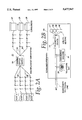
- FIG. 3 is a simplified schematic diagram of the disclosed multiple host MIU telemetry device.
- FIG. 4 is a flow chart depicting a programming methodology used to configure the MIU telemetry device with host attributes.
- FIG. 5 is a flow chart depicting the operational flow of the disclosed multiple host telemetry device.
- FIG. 2A shows a multiple host dial-inbound AMR system 22.
- the system is configured such that a plurality of consumers 24, 25 and 26 are each connected to the central office switch 28 via conventional subscriber telephone lines 30.
- multiple host also connected to central office switch 28 via conventional dial-up telephone lines 30 are one or more hosts, namely host 1, host 2, host 3 and host 4 respectively.
- hosts namely host 1, host 2, host 3 and host 4 respectively.
- telemetry devices located at the consumer premises will dial into a host at an appointed time and date so as to exchange telemetry data with the host.
- a multiple host telemetry device 34 (or MIU) is connected to the subscriber telephone line 30.
- MIU meter interface unit
- the design of this MIU (meter interface unit) telemetry device 34 is such thatit can share the telephone line with other telephone devices which the subscriber might connect to the line, such as a subscriber telephone set 35, an answering machine 36 or a FAX (facsimile) machine, a computer modem, etc.
- the telephone line can also be dedicated to serving only MIU telemetry device 34, if desired.
- the MIU telemetry device 34 Connected to the MIU telemetry device are one or more utility meters 37, 38, 39 and 40 which can be electrically interrogated to ascertain the value of consumed commodity shown on the face of the meter (called the meter register).
- the novel design of the multiple host MIU telemetry device 34 allows it to retain the dial-inbound attributes for a plurality of hosts. This innovation enables the MIU to communicate with a plurality of hosts, each host independently having its own appointment time and telephone number.
- the multiple host MIU telemetry device 34 is connected to four utility meters, namely a gas meter 37, a water meter 38, an electric meter 39, and another meter 40 as desired for a particular application.
- each utility company has a host computer system (host station) dedicated to collecting the amount of commodity consumed at their metering point. That is, there are four hosts, namely hosts 1, 2, 3 and 4 each dedicated to reading their particular utility meter.
- hosts stations 1, 2, 3 and 4 of FIG. 2A would correspond to a gas company host station, a water company host station, an electric company host station, and another host station, respectively.
- MIU telemetry device 34 In keeping with its multiple host capability, MIU telemetry device 34 independently retains the reporting schedule for each host station's utility meter. Thus, at a first appointment time (call-in time), the dial-inbound MIU telemetry device 34 will be activated to call, for example, the gas company host (host 1) to report the amount of gas commodity delivered to a customer premises. Similarly, at a second appointment time, MIU 34 will again be activated to call the water companyhost (host 2) to report the reading of the water meter. At a third appointment time, the MIU would call into the electric company host (host 3) to report the electric meter reading. And finally, at a fourth appointment time, the MIU would call into host 4 to provide a respective consumption information reading thereto.
- the gas company host host 1
- host 2 the water companyhost
- host 2 the water companyhost
- the MIU would call into the electric company host (host 3) to report the electric meter reading.
- the MIU would call into host 4 to provide a respective consumption
- this dial-inbound MIU enables it to communicate with a plurality of independent hosts (i.e. host stations).
- a conventional system would require four single host MIU telemetry devices (each connected to one utility meter and each dedicated to calling only one host) to collect consumption information from the four utility meters.
- one multiple host MIU can replace a plurality of conventional single host MIUs and, in these applications, is a significantly more economical solution.
- FIG. 3 shows a simplified schematic of a dial-inbound MIU telemetry device 34 incorporating the preferred embodiment of the invention.
- MIU telemetry device 34 the entire operation of the telemetry device is underthe program control of a microcontroller or microprocessor. Therefore, the operational characteristics of the MIU are determined by a software program being executed by the resident microcontroller as will be described in more detail subsequently.
- Telemetry device 34 includes input terminals 30A and 30B which are telephone line input terminals that are coupled to phone line 30.
- MIU 34 includes a microcontroller U1 connected to one or more meter interface ports M1-M4. These meter interface ports are connected to electrically encoded registers on the utility meters (not shown) and can be interrogated by microcontroller U1 using a predeterminedserial protocol. In this manner, microcontroller U1 can read the value shown on the face of the utility meter. This value will be uploaded to thehost computer system as telemetry data.
- the electrically encoded meter register could be, for example, a Kent model C700 water meter with encodedregister or a Landis & Gyr model DEMS electric meter.
- a variety of other electrically readable utility meters are also commercially available and can be interfaced to microcontroller U1 by those skilled in the art.
- Microcontroller U1 actually includes a microprocessor core and digital memory in the form of a RAM 45 (random access memory) and ROM 47 (read only memory).
- the ROM contains the firmware for the telemetry device and puts the entire operation of the MIU under the program control of the microcontroller. While the ROM memory can be read but not altered, RAM memory can be changed under program control and is used to store program variables, or other temporary data which the program might need for later use.
- this microcontroller is usually a single chip semiconductor device such as the Motorola M68HC05 which contains on-board ROM and RAM.
- EEROM electrically erasable ROM
- EEROM U2 is connected tomicrocontroller U1 to serve as a nonvolatile memory for the MIU.
- EEROM U2 is a model XL93C46 EEROM manufactured by Exel.
- certain microcontrollers such as the Motorola HC11 series of microcontrollers also contain on-chip EEROM memory which could provide the same functionality as the discrete nonvolatile memory U2, if desired.
- a real time clock U3 is also connected to microcontroller U1 of dial-inbound telemetry device 34 of FIG. 3. This clock is programmed with an alarm time and date so as to activate the dial-inbound MIU to call intoa host at a designated time.
- the microcontroller U1 can configure the real time clock under program control and can set both the current time and thealarm time.
- the microcontroller can also read the current time kept by the real time clock.
- a single chip commercially available component which is well suited to this task and which can be readily interfaced to a microcontroller by those skilled in the art is the Ricoh RP5C15.
- a telephone line status indicator 50 is also connected to microcontroller U1. Through this complex device, microcontroller U1 is kept informed of the current status of the phone line.
- the components contained in line status indicator 50 are a static off-hook detector 52 and a dynamic off-hook detector 54.
- Static off-hook detector 52 prevents telemetry device 34 from attempting toseize telephone line 30 if phone line 30 is already in use, thereby preventing it from possibly interfering with an in-progress telephone call. More particularly, static off-hook detector 52 provides a static off-hook detector signal at output 52A which instructs microcontroller U1 not to seize the phone line (go off-hook) when phone line 30 is already inuse.
- static off-hook detector which is suitable for use as static off-hook detector 52 is described in my patent "Signal Processing Circuit for use in Telemetry Devices", U.S. Pat. No 5,202,916, the disclosure of which is incorporated herein by reference.
- dynamic off-hook detector 54 is used to immediately hang-up telemetry device 34 inthe event that a user telephone, or other telephone device, coincidentally comes off-hook thereby interrupting an on-going telemetry session. More particularly, dynamic off-hook detector 54 provides a dynamic off-hook detector signal at output 54A which informs microcontroller U1 when a usertelephone or other telephone devices comes off-hook while the telemetry device is carrying on a telemetry exchange with the host. When this occurs, microcontroller U1 causes telemetry device 34 to immediately hang-up and relinquish the phone line by opening relay K1.
- Dynamic off-hook detectors which are suitable for use as dynamic off-hook detector54 are described in my patent "Outbound Telemetry Device", U.S. Pat. No. 5,204,896 and in my patent applications “Telemetry Device Including a Dynamic Off-Hook Detector” (Ser. No. 08/128,865) and “Telemetry Device Including a Dynamic Off-Hook Detector Capable of Operating in a Pulse-Dialing Environment” (Ser. No. 08/128,864), the disclosures of each of which are incorporated herein by reference.
- a modem 60 which is connected to phone line 30 via hybrid transformer T1.
- telemetry device 34 can seize the telephone line and draw loop current (approximately 50 mA) from the central office switch. With relay K1 energized, hybrid transformer T1 appears as a 600 ohm load required to properly terminate the off-hook telephone line.
- the central office switch knows that a telephone device is off-hook and will initially provide dial tone to the off-hook telephone device.
- modem 60 includes a DTMF (dual tone multifrequency) dialer which is under the program control of microcontroller U1, thereby enabling the telemetry device to call into a host system.
- DTMF dual tone multifrequency
- a variety of commercial manufacturers sell modems which can be used for this application.
- the entire modem could be a single chip integrated circuit such as the SC11016 "300/1200 bit per second modem" with DTMF dialer manufactured by Sierra Semiconductor, if desired.
- Microcontroller U1 configures the operation of modem 60 by sending instructions to set the baud rate and other communication parameters via control lines 62 (CNTL) thereby preparing it for a telemetry transaction.
- data sent from the host to the MIU telemetry device 34 appears on the receive data (RXD) output of modem 60 while data to be sent from the MIU to the host is placed on the transmit data (TXD) input of the modem 60 by microcontroller U1. Since both transmit and receive data is accessible to microcontroller U1, the telemetry device is capable of sending data to and receiving data from a host.
- modem 60 is a hardware peripheral to the microcontroller whichinterfaces the telemetry device to and facilitates the transport of telemetry data over telephone line 30.
- an asynchronous communications protocol is used to send binary words in a serial format.
- an 8 bit digital word i.e. a byte
- a start bit i.e. a start bit
- a stop bit i.e. a stop bit
- These extra bits act as place holders and allow modem 60 to serially transfer 8 bits of data at a time (i.e. one binary word) with an arbitrary pause between transfers of binary words, since computers such as microcontrollerU1 only communicate in multiples of whole binary words.
- a device which automatically handles this protocol is called a UART (universal asynchronous receiver-transmitter) and is commercially available from a variety of semiconductor manufacturers.
- Such a UART can be used to take the serial output of a modem, such as 60, and present an 8 bit word (a byte) to a device, such as a microcontroller U1.
- a modem such as 60
- a microcontroller U1 for an excellent treatise on asynchronous communication the reader is referred to "Technical Aspects of Data Communications", by John E. McNamara, Digital Press, 1977, LCCC number 77-93590.
- microcontroller U1 includes an SCI 64 which is directly coupled to the output of the modem 60.
- SCI 64 is capable of generating an internal interrupt to the microcontroller each time a binary word is received from a particular host station. The microcontroller can then check the contentsof its UART register (not shown) to determine when a character has been received from a host station.
- Resistor R1 and diode D1 serve to isolate modem 60 from microcontroller U1 and allow an RS-232-C programming terminal (not shown) to be connected to MIU telemetry device 34 via programming port 70.
- the configuration or set-up of an MIU 34 for operation in a target AMR system is accomplished by the initial programming of certain software variables, including respective dial-inbound attributes (such as call-in times and host telephone numbers) to be logically associated with each of a plurality host stations. Normally the terminals P-RXD, P-TXD and DTR/RTS of programming port 70 are left unconnected (i.e.
- resistor R1 and diode D1 normally do not impede the flow of logic level signals passing from the modem 60 to microcontroller U1.
- the RS-232-C programming terminalcould also be the serial port of a PC, laptop computer or other device capable of emulating the RS-232-C serial communications protocol.
- asynchronous signals sent from microcontroller U1 to be displayed on the programming terminal (to its P-TXD transmit port) are coupled to it through buffering inverter 80.
- microcontroller U1 Upon detecting the presence of the programming terminal, microcontroller U1 will instruct modem 60, via commands sent on the CNTL lines, to force the RXD output of the modem 60 to a continuous logic high level. Consequently, asynchronous data signals, corresponding to characters typed on the programming terminal's keyboard (to its P- RXD receive port), will be coupled through inverter 75and diode D1 and will be readable by microcontroller U1.
- the programming terminal connected to the programming port 70 of the MIU is, essentially, in parallel with the input and output of the modem 60. While this conserves I/O (input/output) ports on the microcontroller, it also enables an installer or host station to program the MIU over the normal telephone line via the existing modem 60. This has a distinct advantage inthat the programming of the MIU telemtry device can be performed without physically being in close proximity to the MIU telemetry device. Therefore, the MIU can be programmed either by connecting an industry standard RS-232-C terminal to its programming port 70 or by commands sent over the telephone line from a remote host station when the MIU calls in to the host station, or from another source.
- MIU telemetry device 34 stores dial-inbound attributes (such as call-in time and the telephone number) for each host station of the plurality of host stations.
- dial-inbound attributes such as call-in time and the telephone number
- a memory lookup table is created in non-volatile memory, U2, which enables the MIU to store, and subsequently retrieve, the dial-inbound attributes for a plurality of host stations under program control of microcontroller U1 or a microprocessor.
- Table 1 below shows a preferred organization for a lookup table which is capable of storing the dial-inbound attributes for up to four hosts, although thisnumber could be lessened or increased in accordance with the requirements of the particular application.
- the dial-inbound attributes for each host include two strings of data containing an appointment time (call-in time) and a corresponding host telephone number, respectively. Since this particular MIU 34 can function with up to four hosts, there are a total of eight character strings of data which need to be stored in non-volatile memory. Four character strings contain call-in time information and the remaining four character strings contain host telephone numbers.
- Each memory block labeled E01 through E08 in Table 1 below, contains two pointers, the first pointing tothe memory location in memory U2 where the data string begins and the second pointing to the memory location in memory U2 where the same data string ends. Thus, regardless of the actual length of the data strings stored in non-volatile memory U2 of FIG. 3, the structure of the lookup table remains constant since it only contains pointers to other memory locations.
- the memory is "fixed partitioned", meaning that each data field has a predetermined starting position in memory and predetermined maximum length. Consequently, the starting address in Table 1 for each data filed is known while the end pointer can vary with the actual length of the data field.
- the predetermined start address (a constant) is stored in program ROM 47 while the end address (which is a true variable) is stored in non-volatilememory U2, along with the actual data.
- both the start and end addresses could be stored in the non-volatile memory; for instance, this would be necessary if the memory space were to be dynamically assigned or if it were desirable to change the fixed partitioning of the memory space without changing the firmware.
- each memory block shown in Table 1 includes a pair of pointers into nonvolatile memory space, it is not a requirement that the pointers be stored in either contiguous memory, or even the same type of memory, so long as the memory arrangement is known in advance.
- the lookup table is organized so that two memory blocks are assigned to each host station, thereby providing pointers to the nonvolatile memory locations where the host telephone number and corresponding appointment time (call-in time) will be stored.
- memory block E01 contains the pointers to the memory locations where the host telephone number is stored while memory block E02 contains pointers to the memory locations where the host appointment time is stored. Consequently, memory blocks E01and E02 contain the pointers for the dial-inbound attributes for the first host station.
- the dial-inbound attribute pointers for host 2 are stored in memory blocks E03 and E04.
- thedial-inbound attribute pointers for host 3 are stored in memory blocks E05 and E06 while those for host 4 are stored in memory blocks E07 and E08.
- MIU 34 can be programmed by either connecting an RS-232-C ASCII terminal to its programming port 70 or by commands communicated by a host station and over the telephone line through modem 60 of the MIU. Once connected in this manner, the programmer can enter configuration data such as host attributes and subsequently store such data in non-volatile memory U2.
- the flow chart shown in FIG. 4 depicts a procedure for programming the dial-inbound attributes for a plurality of host stations into a multiple host dial-inbound MIU. This procedure is implemented in the program or firmware which is stored in ROM 47 and whichcontrols the operation of the MIU telemetry device.
- the MIU is receptive to data communication signals when either condition is true, in which case control will pass to functional block 305 which displays an "*" (asterisk) on the terminal's display, to confirm to the programmer (installer) that the MIU is ready for command input, before passing control to decision block 310 which waits for an input command consisting of a string of characters followed by a carriage return (CR).
- a variety of high level commands may be entered into the MIU either from a terminal at port 70 or via a connected host station.
- Such commands enable the personality of the MIU telemetry device to be uniquely configured for operation in a specific application.
- a command which begins with the characters "@E" followed by two numeric digits allows configuration data (host attributes) to be manually entered and stored in the memory blocks depicted in Table 1 above.
- the @E command indicates that data is going to be put into EEROM U2 at the specified memory block (i.e. @E01, for host 1's telephone number, as shown in Table 1 above).
- the @E01 command indicates that the character string following the @E01 command should be placed in memory block E01.
- the @E02 command indicates that the character string following the @E02 command should be placed in memory block E02, and so forth.
- the data (character string) following the @E command is either a telephone number or a time stamp (call-in time) in this particular embodiment.
- the dial-inbound attributes for host 1 the following two commands would be entered: "@E01 1234567690” and "@E02 MM/DD/YY HH:MM.” This causes the phone number "1234567690" to be stored in memory block E01 and the call-in time "MM/DD/YY HH:MM" to be stored in memory block E02.
- the MIU would dial host 1 at telephone number 1234567890 on day DD of month MM in the year 19YY at time HH hours, MM minutes.
- control is transferred to derision block 315 which checks for a valid command. If the command entered by the programmeris not recognized, control passes to function block 320 and the telemetry device responds with "?" indicating that the command was not recognized. Control is then returned to derision block 310 for the entry of another command.
- control is transferred from derision block 315 to decision block 325 which checks the first two characters entered by the installer. As discussed above, if the command begins with an "@E" then it pertains to the programming of the dial-inbound attributesand control is passed to derision block 330. Otherwise, control is transferred to function block 335 which services all other valid commands.Assuming the entry of an @E command, decision block 330 will retrieve the number of the memory block to be programmed from the input string. This number is contained in the two digit numeric characters following the @E command. For instance, as previously mentioned, @E01 indicates that the first memory block in the non-volatile memory is to be programmed with thedata appended to the command. If the memory block is invalid, control is returned function block 320, which causes a "?" to be displayed, before returning control to derision block 310 for the re-entry of the correct data.
- control is transferred to derision block 340 which checks the remaining characters in the input string for proper format. Since the data following an @E command is eithera telephone number or a time stamp in this particular embodiment, the data in the remaining string must be numeric for phone numbers and in the designated time-date (MM/DD/YY HH:MM) format for the time stamp. It is noted that for reasons which will become apparent later, it is acceptable to program a zero value for one or both dial-inbound host attributes. If the command argument is invalid, control is transferred first to function block 320 and then to derision block 310, thereby displaying a "?" while waiting for the command to be re-entered. Otherwise, control is transferred to function block 345.
- Function block 345 retrieves the starting pointer for the designated memoryblock in preparation for the writing of data at a first starting location in nonvolatile memory U2. Recalling that the organization of non-volatile memory U2 is fixed partitioned, as previously discussed, this starting memory pointer is retrieved from program ROM 47 and copied into RAM 45. Control then passes to function block 350 which causes the host attributes(data) to be written into non-volatile memory U2. As each character in the string is written into contiguous memory, the value of the RAM start pointer is incremented by one. Consequently, when the entire data string has been written into non-volatile memory U2, the pointer to the end address for the string data field is known.
- control passes to function block 355 which completes the storage procedure by writing the value of the end pointer (for the just stored data string) into the lookup table shown in Table 1 above. Consequently, both the host attribute data string and end pointer have been written intonon-volatile memory, completing the storage procedure for the given memory block. With this data safely stored in memory U2, control then passes to function block 360 which causes an "
- the preferred method of programming the MIU telemetry device depicted in FIG. 3 is by having the installer enter only a minimal number of parameters, including the telephone number for a master host, and let the MIU telemetry device call into the master host and be remotely programmed with host attributes from the master host over the telephone line.
- the master host uses all the same @E commands to program respective the dial-inbound attributes for each of the hosts, except that the procedure is fully automatic.
- the MIU is receptive to commands other than the @E commands, used to write the values of various dial-inbound parameters to the non-volatile EEROM.
- commands other than the @E commands used to write the values of various dial-inbound parameters to the non-volatile EEROM.
- an @D command is used to set the date on real time clock U3 while the @T commandsets its time.
- Entering the command "PRO” causes the MIU to prompt the installer for several basic parameters, including a phone number for host 1. When these parameters have been entered, entering the command "GO 1" will cause the MIU to call that phone number and be remotely programmed bythe master host.
- the programming host master host uses the same @E commands as the manual procedure previously described. As a result, the MIU can be completely programmed and configured by a remote programming host which has access to a system-wide database of MIU parameters.
- a plurality of dial-inbound attributes are retained in a memory lookup table.
- memory blocks E02, E04, E06 and E08 contain pointers to the memory locations in non-volatile memory U2 which store the scheduled appointment times for hosts 1, 2, 3 and 4, respectively.
- microcontroller U1 periodically scans through this table and ascertains when a specific appointment time (call-in time) has become history; that is, when the target date and time has become history with respect to the current date-time kept by real time clock U3.
- microcontroller U1 will then look up the corresponding host station's telephone number, subsequently using that number to dial into that host for a telemetry transaction.
- Memory blocks E01, E03, E05 and E07conta in the pointers to the memory locations which store the telephone numbers for hosts 1, 2, 3 and 4, respectively.
- FIG. 5 shows a flow chart depicting the operating methodology for a multiple host MIU telemetry device 34 in more detail. This methodology of this flow chart is incorporated in software of ROM 47 which controls the operation of microcontroller U1 and telemetry device 34.
- process flow begins with the initialization of avariable MBP (memory block pointer) to the value of two, in function block 500.
- avariable MBP memory block pointer
- pointers to the dial-inbound host attributesfor a plurality of hosts are retained in the memory blocks of a lookup table. Recalling Table 1, the pointers for the host appointment times are stored in memory blocks E02, E04, E06 and E08 for hosts 1, 2, 3, and 4, respectively.
- the pointers for each host's appointment time can be retrieved from the lookup table.
- the initialization of the variable MBP to the numeric value 2 points it to the memory block E02,hence to the memory locations where the first host's appointment time is stored.
- Control then passes to derision block 505 which is the beginning of a process loop which checks to see if the value of the variable MBP is greater than 8.
- control is transferred to function block 510 which fetches the memory pointers at memory block MBP from the lookup table. Since MBP is equal to two, the pointers in memory block E02 reference the location in nonvolatile memory U2 where the first host's (host 1's) appointment time is stored. Control then passes to function block 515 which retrieves this appointment time before passing control to decision block 520 which looks for a zero value appointment time. The significance of a zero value appointment time will be explained shortly, but for the moment the appointment time is assumed to be a valid and, therefore, non-zero.
- the pointers in memory block E04 reference the location in memory where the second host's (host 2's) appointment time is stored. Assuming, for the moment, that no host appointment time is due, the loop just described through flow chart blocks505, 510, 515, 520, 525, 530 and 535 will repeat. When control returns to decision block 505, the value of MBP will be six and the appointment time for host 2 will have been checked. Next, the loop will repeat again this time checking the appointment time for host 3, under pointers contained inmemory block E06. The value of MBP will now be 8 and the loop will repeat again, checking the appointment time for host 4 contained in memory block E08, as control is again returned to derision block 505.
- an MIU capable of operating in a multiple host environment use all of its multiple host capability.
- the telemetry device described can accommodate up to four hosts, it can also operate with any lesser number of hosts.
- the unused appointment times for the unused hosts are programmed with zeros, an invalid appointment time.
- derision block520 will result in control being transferred to function block 535, therebyincrementing the MBP by two and effectively bypassing an empty entry in thehost lookup table.
- decision block 530 will transfer control away from the scan loop to functional block 540 which will fetch the pointers from memory block MBP-1, corresponding to the memory locations where that host's telephone number is stored. Control next passes to functional block545, which retrieves the telephone number for the host whose appointment time has arrived, before passing control to derision block 550 which checks for a zero value, an invalid telephone number.
- any dial-inbound attribute to a zero value.
- the intention is to effectively remove such a host from the lookup table if either attribute is set to zero. Consequently, if decision block 550 determines that a host telephone number is zero, control will be transferred to function block 535 which will increment the value of MBP by two, effectively bypassing the zero table entry for that host and moving on to the next memory block, corresponding to the next host in the table. Assuming the telephone numberis valid, control will be passed to function block 555 thereby causing the MIU to dial the corresponding host's telephone number to establish a data connection with the host.
- Control next passes to function block 560 wherein the host opens a meter port on the MIU and interrogates its utility meter in the ensuing telemetry session.
- the MIU has a plurality of meter ports, each host station is only provided with the specific commands which will enablethat host to read a specific meter port or ports. Consequently, in one embodiment, a particular host is limited to reading only those meters (meter ports) which it has been specifically authorized to access because of the fact that the particular host is not equipped with the command codes needed to read other meter ports. For example, as discussed below, host 1 could be provided with the specific commands which enable it to instruct the MIU to read meter port M1, but not the other ports.
- host 2 could be provided with the specific command to enable it to instruct the MIU to read meter port M2 and meter port M3.
- control is passed to function block 535 which again increase the value of MBP by two, thereby moving on to check the appointment time for the next host in the lookup table.
- the MIU telemetry device With respect to the interrogation of the utility meter, as part of the initial configuring of the MIU telemetry device, the MIU telemetry device knows, via configuration data stored in its nonvolatile memory as part of its programming, the type of utility meter attached to each active meter port. Consequently, the MIU is able to electronically interrogate each utility meter so as to retrieve the reading shown on the meter's register.Via a high level command, similar to the "@E", “@D”, "@T” commands previously described, the host instructs the MIU to read a specific meter port and the MIU will automatically select the appropriate serial communication protocol for the selected meter, interrogate that meter, andupload the readings as telemetry data to the on-line host.
- the host would send the command @M01 which would cause the MIU to read the designated meter port, namely meter port M1.
- the host would only be provided with the commands to read certain meter ports thereby enabling it to read its own utility meter, or meters, but not those of another utility company.
- host 1 would be provided with the @M01 command so that it could instruct the MIU to read information from the M1 meter port.
- host 1 would not be provided with the @M02, @M03and @M04 commands and thus host 1 would not be able to cause reading from meter ports M2, M3 and M4.
- host 2 can be provided with the @M02 and @M03 commands. In this manner, host 2 can cause the MIU to take readings of information from meter ports M2 and M3, but not meter ports M1and M4.
- a connected host station can reprogram any of the dial-inbound attributes using the same methods previously described for the "@E" command. Since the dial-inbound MIU calls only calls into a host station when its appointment time has expired, it is a normal part of the telemetry transaction for the host to, at least, update the appointment time. However, in practice, the host can modify or update any of the dial-inbound parameters while the telemetry device is on-line. Consequently, for a multiple host telemetry device, each host can at leastmodify or update its own dial-inbound parameters and could, if desired, modify other dial-inbound parameters.
- each of the plurality of host stations to which the multiple host MIU communicates are independent host stations in that each host station has its own telephone number and its own appointment time independent of the other host stations. This is to bedistinguished from the case of a conventional single host MIU which employsa backup telephone number which is only dialed in the event that the host does not answer at the first telephone number the MIU dials. It is noted that the second telephone number is not dialed if the MIU is successful with the host at the first telephone number.
- the multiple host telemetry device taught herein is combined with the data activation technique and telemetry device taught in my copending patent application entitled "APPARATUS AND METHOD FOR ON-DEMAND ACTIVATION OF TELEPHONE LINE TELEMETRY DEVICES", (Docket No. P95-K-005).
- This combined alternative embodiment of the telemetry device is now described in more detail. Recalling that a dial-inbound telemetry device calls into a host on appointment, the device is inaccessible to the host except at those times when it calls into the host. To overcome this limitation, conventional devices incorporate various methods to make them on-demand activatable.
- One technique for providing this on-demand capability involves ringing thesubscriber telephone line a specified number of times. Still another technique requires that someone or something (e.g. an answering machine, FAX, etc.) answer the ringing telephone line whereafter an activating tonesignal will be sent.
- the telemetry device in response to receiving the specified number of rings or upon reception of the activating tone signal, the telemetry device will, in the first case, callback to the host, and, in the second case, will immediately go off-hook to engage in a telemetry transaction with the on-line host which activated it. It is noted that these telemetry devices were single host telemetry devices.
- the data activating signal from a host includes information which enables the telemetry device to ascertain which particular host (i.e. host 1, host2, host 3, etc.) has on-demand activated it.
- the multiple host telemetry device can then call into the particular host which activated it.
- any one of the utility company hosts couldon-demand activate the multiple host MIU, using the data activation methodology described in my copending patent application (DOCKET NO. P95-K-005.)
- the reception of the data activating signal would result in the MIU calling the corresponding host, since the data activation signal identities the particular activating host. This would cause the MIU to over-ride the appointment time dial-inbound attribute and call into the host on-demand.
- the reception of a data activating signal which corresponds to a particular host causes the MIU to access the host attribute (call-in telephone number) which corresponds to the particular host. Using the accessed attribute, namely the call-in telephone number, the MIU then dials into the particular host.
- a method of operating this telemetry device is also disclosed. More particularly, a method for collecting information by a multiple host telemetry device at a remote location is disclosed.
- the telemetry device transmits collected information over a phone line to one of a plurality ofhost stations.
- the telemetry device includes at least one meter port.
- the method of operating the multiple host telemetry device includes the step of storing in a memory in the telemetry device respective host attributes for each of the plurality of host stations.
- the method also includes the step of accessing by a processor in the telemetry device the host attributes in the memory thus providing accessed host attributes.
- the method further includes the step of determining from the accessed host attributes which host station of the plurality of host stations to call over the phone line to report information from the at least one meter port.
- a multiple host telemetry device is not required to have multiple ports.
- one embodiment of the multiple host telemetry device includes a plurality of meters, each associated with a corresponding host, an MIU telemetry device with a single meter port is still capable of operating in a multiple host environment.
- an MIU telemetry device with only a single meter port can call into different hosts so as to make the consumption information available to different hosts for entirely different reasons.
- the MIU can have an independent appointment time with each host at a corresponding host telephone number.
- a single port MIU connected to a water meter could be programmed to call the water company monthly (assuming a monthly billing cycle) and can also have a weekly appointment with a second host (e.g. a county water management center) to facilitate closer monitoring of water resource usage.
- a second host e.g. a county water management center
Abstract
Description
                                  TABLE 1
__________________________________________________________________________
Lookup Table for a Four Host Station Telemetry Device
                MEMORY POINTERS
                            MEMORY BLOCK
__________________________________________________________________________
 HOST 1
     Telephone Number String
                 Start Addr. 1
                       End Addr. 1
                             E01
                                       HOS
HOST 1
    Appointment Time String
                Start Addr. 2
                      End Addr. 2
                            E02
 HOST 2
     Telephone Number String
                 Start Addr. 3
                       End Addr. 3
                             E03
                                       HOS
HOST 2
    Appointment Time String
                Start Addr. 4
                      End Addr. 4
                            E04
 HOST 3
     Telephone Number String
                 Start Addr. 5
                       End Addr. 5
                             E05
                                       HOS
HOST 3
    Appointment Time String
                Start Addr. 6
                      End Addr. 6
                            E06
 HOST 4
     Telephone Number String
                 Start Addr. 7
                       End Addr. 7
                             E07
                                       HOS
HOST 4
    Appointment Time String
                Start Addr. 8
                      End Addr. 8
                            E08
__________________________________________________________________________
Claims (36)
Priority Applications (1)
| Application Number | Priority Date | Filing Date | Title |
|---|---|---|---|
| US08/519,526 US5677947A (en) | 1995-08-25 | 1995-08-25 | Apparatus and method for operating a telephone line telemetry device in a multiple host environment |
Applications Claiming Priority (1)
| Application Number | Priority Date | Filing Date | Title |
|---|---|---|---|
| US08/519,526 US5677947A (en) | 1995-08-25 | 1995-08-25 | Apparatus and method for operating a telephone line telemetry device in a multiple host environment |
Publications (1)
| Publication Number | Publication Date |
|---|---|
| US5677947A true US5677947A (en) | 1997-10-14 |
Family
ID=24068686
Family Applications (1)
| Application Number | Title | Priority Date | Filing Date |
|---|---|---|---|
| US08/519,526 Expired - Lifetime US5677947A (en) | 1995-08-25 | 1995-08-25 | Apparatus and method for operating a telephone line telemetry device in a multiple host environment |
Country Status (1)
| Country | Link |
|---|---|
| US (1) | US5677947A (en) |
Cited By (7)
| Publication number | Priority date | Publication date | Assignee | Title |
|---|---|---|---|---|
| US6347135B1 (en) | 2000-05-02 | 2002-02-12 | Teldata, Inc. | Apparatus and method for powering a telephone-based inbound telemetry device |
| US20020143478A1 (en) * | 2001-02-02 | 2002-10-03 | Vanderah Richard Joseph | Reporting regulator for managing a gas transportation system |
| US6487282B1 (en) | 2000-07-31 | 2002-11-26 | Firstpoint Energy Corp. | Apparatus and method for an inbound telemetry device to sense telephone line status |
| US20030058129A1 (en) * | 2001-09-25 | 2003-03-27 | Lg Electronics Inc. | Automatic meter reading system and method using telephone line |
| US20030088555A1 (en) * | 2001-10-16 | 2003-05-08 | Hidehiko Watanabe | Management system and method, and data processing apparatus |
| WO2003077524A1 (en) * | 2002-03-13 | 2003-09-18 | Enrique Romero Lopez | System for adapting a data and voice transmission local network to an analog telephone line |
| US6784806B1 (en) * | 1998-06-29 | 2004-08-31 | General Electric Company | Electronic electricity meter |
Citations (20)
| Publication number | Priority date | Publication date | Assignee | Title |
|---|---|---|---|---|
| US4180709A (en) * | 1978-02-13 | 1979-12-25 | International Tel Data Corporation | Data collection system using telephone lines |
| US4489220A (en) * | 1983-06-08 | 1984-12-18 | International Teldata Ii Corp. | Test set |
| US4540849A (en) * | 1983-06-08 | 1985-09-10 | International Teldata Ii Corp. | Meter interface unit for utility meter reading system |
| US4578536A (en) * | 1983-10-19 | 1986-03-25 | International Teldata Corp | Centerpoint automatic meter reading system |
| US4646342A (en) * | 1985-09-11 | 1987-02-24 | Itt Corporation | Test trunk access controller |
| US4654869A (en) * | 1985-09-11 | 1987-03-31 | Itt Corporation | Information collecting and forwarding apparatus |
| US4710919A (en) * | 1983-10-21 | 1987-12-01 | International Teldata Corporation | Multiplex system for automatic meter reading |
| US4833618A (en) * | 1986-02-20 | 1989-05-23 | Net Laboratories, Inc. | System for automatically reading utility meters from a remote location |
| US4839917A (en) * | 1987-10-29 | 1989-06-13 | Oliver Stewart W | Universal line status monitoring and response system |
| US4866761A (en) * | 1986-06-20 | 1989-09-12 | Badger Meter, Inc. | Automatic meter reading system |
| US5134650A (en) * | 1991-01-22 | 1992-07-28 | Schlumberger Industries, Inc. | Dial inbound meter interface unit (MIU) for automatic meter reading using no subscriber line access controller |
| US5189694A (en) * | 1990-08-31 | 1993-02-23 | At&T Bell Laboratories | Telemetry access arrangement |
| US5202916A (en) * | 1990-08-10 | 1993-04-13 | Telegenics Inc. | Signal proessing circuit for use in telemetry devices |
| US5204896A (en) * | 1990-08-10 | 1993-04-20 | Telegenics, Inc. | Outbound telemetry device |
| US5235634A (en) * | 1990-12-14 | 1993-08-10 | Telegenics, Inc. | Apparatus and method for activating an inbound telemetry device |
| US5234644A (en) * | 1990-08-27 | 1993-08-10 | Ems-Inventa Ag | Process for producing ultra-high molecular weight polyamide fibers |
| US5434911A (en) * | 1993-06-04 | 1995-07-18 | M & Fc Holding Company, Inc. | Call in-bound remote reading and data collection system |
| US5454031A (en) * | 1993-06-04 | 1995-09-26 | M & Fc Holding Company, Inc. | Dial inbound meter interface unit which derives its power from a telephone line |
| US5485509A (en) * | 1993-09-29 | 1996-01-16 | Telegenics, Inc. | Telemetry device including a dynamic off-hook detector |
| US5488654A (en) * | 1993-09-29 | 1996-01-30 | Telegenics, Inc. | Telemetry device including a dynamic off-hook detector capable of operationg in a pulse-dialing environment |
-
1995
- 1995-08-25 US US08/519,526 patent/US5677947A/en not_active Expired - Lifetime
Patent Citations (20)
| Publication number | Priority date | Publication date | Assignee | Title |
|---|---|---|---|---|
| US4180709A (en) * | 1978-02-13 | 1979-12-25 | International Tel Data Corporation | Data collection system using telephone lines |
| US4489220A (en) * | 1983-06-08 | 1984-12-18 | International Teldata Ii Corp. | Test set |
| US4540849A (en) * | 1983-06-08 | 1985-09-10 | International Teldata Ii Corp. | Meter interface unit for utility meter reading system |
| US4578536A (en) * | 1983-10-19 | 1986-03-25 | International Teldata Corp | Centerpoint automatic meter reading system |
| US4710919A (en) * | 1983-10-21 | 1987-12-01 | International Teldata Corporation | Multiplex system for automatic meter reading |
| US4646342A (en) * | 1985-09-11 | 1987-02-24 | Itt Corporation | Test trunk access controller |
| US4654869A (en) * | 1985-09-11 | 1987-03-31 | Itt Corporation | Information collecting and forwarding apparatus |
| US4833618A (en) * | 1986-02-20 | 1989-05-23 | Net Laboratories, Inc. | System for automatically reading utility meters from a remote location |
| US4866761A (en) * | 1986-06-20 | 1989-09-12 | Badger Meter, Inc. | Automatic meter reading system |
| US4839917A (en) * | 1987-10-29 | 1989-06-13 | Oliver Stewart W | Universal line status monitoring and response system |
| US5202916A (en) * | 1990-08-10 | 1993-04-13 | Telegenics Inc. | Signal proessing circuit for use in telemetry devices |
| US5204896A (en) * | 1990-08-10 | 1993-04-20 | Telegenics, Inc. | Outbound telemetry device |
| US5234644A (en) * | 1990-08-27 | 1993-08-10 | Ems-Inventa Ag | Process for producing ultra-high molecular weight polyamide fibers |
| US5189694A (en) * | 1990-08-31 | 1993-02-23 | At&T Bell Laboratories | Telemetry access arrangement |
| US5235634A (en) * | 1990-12-14 | 1993-08-10 | Telegenics, Inc. | Apparatus and method for activating an inbound telemetry device |
| US5134650A (en) * | 1991-01-22 | 1992-07-28 | Schlumberger Industries, Inc. | Dial inbound meter interface unit (MIU) for automatic meter reading using no subscriber line access controller |
| US5434911A (en) * | 1993-06-04 | 1995-07-18 | M & Fc Holding Company, Inc. | Call in-bound remote reading and data collection system |
| US5454031A (en) * | 1993-06-04 | 1995-09-26 | M & Fc Holding Company, Inc. | Dial inbound meter interface unit which derives its power from a telephone line |
| US5485509A (en) * | 1993-09-29 | 1996-01-16 | Telegenics, Inc. | Telemetry device including a dynamic off-hook detector |
| US5488654A (en) * | 1993-09-29 | 1996-01-30 | Telegenics, Inc. | Telemetry device including a dynamic off-hook detector capable of operationg in a pulse-dialing environment |
Non-Patent Citations (1)
| Title |
|---|
| Outline Specification For A Meter Interface Unit for use with PSTN No Ring Calls by K.E. Nolde, BT Laboratories May 8, 1993. * |
Cited By (12)
| Publication number | Priority date | Publication date | Assignee | Title |
|---|---|---|---|---|
| US6784806B1 (en) * | 1998-06-29 | 2004-08-31 | General Electric Company | Electronic electricity meter |
| US6347135B1 (en) | 2000-05-02 | 2002-02-12 | Teldata, Inc. | Apparatus and method for powering a telephone-based inbound telemetry device |
| US6487282B1 (en) | 2000-07-31 | 2002-11-26 | Firstpoint Energy Corp. | Apparatus and method for an inbound telemetry device to sense telephone line status |
| US20020143478A1 (en) * | 2001-02-02 | 2002-10-03 | Vanderah Richard Joseph | Reporting regulator for managing a gas transportation system |
| US7049975B2 (en) * | 2001-02-02 | 2006-05-23 | Fisher Controls International Llc | Reporting regulator for managing a gas transportation system |
| US20030058129A1 (en) * | 2001-09-25 | 2003-03-27 | Lg Electronics Inc. | Automatic meter reading system and method using telephone line |
| US7102533B2 (en) * | 2001-09-25 | 2006-09-05 | Lg Electronics Inc. | Automatic meter reading system and method using telephone line |
| US20030088555A1 (en) * | 2001-10-16 | 2003-05-08 | Hidehiko Watanabe | Management system and method, and data processing apparatus |
| US6956934B2 (en) * | 2001-10-16 | 2005-10-18 | Ricoh Company, Ltd. | Management system and method, and data processing apparatus |
| WO2003077524A1 (en) * | 2002-03-13 | 2003-09-18 | Enrique Romero Lopez | System for adapting a data and voice transmission local network to an analog telephone line |
| US20050117723A1 (en) * | 2002-03-13 | 2005-06-02 | Enrique Romero Lopez | System for adapting a data and voice transmission local network to an analog telephone line |
| US7212616B2 (en) | 2002-03-13 | 2007-05-01 | Enrique Romero Lopez | System for adapting a conventional telephone line to a data and voice transmission local network |
Similar Documents
| Publication | Publication Date | Title |
|---|---|---|
| US5577108A (en) | Information distribution system with self-contained programmable automatic interface unit | |
| US4817131A (en) | Automatic meter reading system | |
| US5682422A (en) | Apparatus and method for on-demand activation of telephone line telemetry devices | |
| US4086434A (en) | Remote condition reporting system | |
| US4866761A (en) | Automatic meter reading system | |
| US4975942A (en) | Credit/calling card pay telephone method and system employing telephone unit local card-checking and other intelligence cooperative with local personal host computer | |
| US5046082A (en) | Remote accessing system for cellular telephones | |
| US4833618A (en) | System for automatically reading utility meters from a remote location | |
| US4551581A (en) | Method and apparatus for sending a data message to a selected station during a silent interval between ringing | |
| US5025470A (en) | Automatic meter reading system with malfunction protection | |
| US6282564B1 (en) | Method, system and apparatus for exchanging stored information between a server and customer premises equipment | |
| US5809068A (en) | PCMCIA modem | |
| US5677947A (en) | Apparatus and method for operating a telephone line telemetry device in a multiple host environment | |
| US5892432A (en) | Personal computer control and activation device utilizing a paging message | |
| WO1997047126A1 (en) | Method and apparatus for remote telemetering | |
| US5802158A (en) | Method and apparatus for providing an alarm call to a remotely located user using a DISA line in a private exchange | |
| US4654638A (en) | Security monitoring system | |
| JPS6155150B2 (en) | ||
| CN100484180C (en) | PLC to PLC communications with a modem on the PLCI/O bus | |
| US7113584B2 (en) | Digital communication translator | |
| JPH08186653A (en) | Gas meter check system | |
| JPH0578226B2 (en) | ||
| KR0145479B1 (en) | Keyphone system | |
| JP2597555B2 (en) | Digital switching system | |
| GB2319925A (en) | Remote data access |
Legal Events
| Date | Code | Title | Description |
|---|---|---|---|
| AS | Assignment |
Owner name: INTERNATIONAL TELDATA CORP., ILLINOIS Free format text: ASSIGNMENT OF ASSIGNORS INTEREST;ASSIGNOR:OLIVER, STEWART WARNER;REEL/FRAME:007687/0881 Effective date: 19950823 |
|
| STCF | Information on status: patent grant |
Free format text: PATENTED CASE |
|
| FEPP | Fee payment procedure |
Free format text: PAYOR NUMBER ASSIGNED (ORIGINAL EVENT CODE: ASPN); ENTITY STATUS OF PATENT OWNER: SMALL ENTITY |
|
| FPAY | Fee payment |
Year of fee payment: 4 |
|
| AS | Assignment |
Owner name: FIRSTPOINT ENERGY CORPORATION, OREGON Free format text: ASSIGNMENT OF ASSIGNORS INTEREST;ASSIGNOR:TELDATA SOLUTIONS LLC;REEL/FRAME:012875/0061 Effective date: 20020327 |
|
| REMI | Maintenance fee reminder mailed | ||
| FPAY | Fee payment |
Year of fee payment: 8 |
|
| SULP | Surcharge for late payment |
Year of fee payment: 7 |
|
| REMI | Maintenance fee reminder mailed | ||
| FPAY | Fee payment |
Year of fee payment: 12 |
|
| SULP | Surcharge for late payment |
Year of fee payment: 11 |